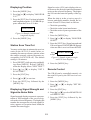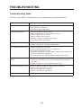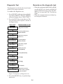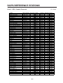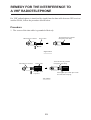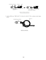
1
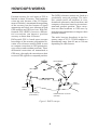
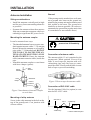
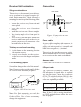
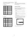
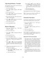
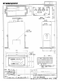
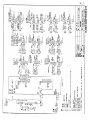
DGPS BEACON RECEIVER
MODEL
GR-80
C
Yo u r L o c a l A g e n t / D e a l e r
9-52, Ashihara-cho,
Nishinomiya, Japan
Te l e p h o n e :
Te l e f a x :
0 7 9 8 - 6 5 - 2 111
0798-65-4200
All rights reserved.
Printed in Japan
PUB. No. OME-43830
(YOSH)
GR-80
FIRST
EDITION
H
:
:
APR. 1997
MAR. 13, 2001
SAFETY INSTRUCTIONS
CAUTION
WARNING
Do not open the equipment.
Hazardous voltage which can
cause electrical shock, burn or
serious injury exists inside the
equipment. Do not work inside
the equipment unless familiar
with electrical circuits.
Position should always be checked
against other sources to confirm
reliability.
GPS position and velocity accuracies are
controlled by the U.S. Department of
Defense.
Turn off the equipment whenever you
feel it is abnormal.
Continued use may damage the equipment.
The useable temperature range of the
display unit is -15°C to +55°C.
Use in temperature out of the above range
may damage the equipment.
Confirm that the power supply voltage
is compatible with the voltage rating
of the equipment.
Connection to the wrong power supply
can cause fire or equipment damage. The
voltage rating appears on the label at the
rear of the display unit.
Keep the compass safe distance.
Standard compass
0.3 m
Steering compass
0.2 m
TABLE OF CONTENTS
FOREWORD
FOREWORD ............................................. 1
A Word to GR-80 Owners ....................... 1
Features ................................................... 1
SPECIFICATIONS .................................... 2
SYSTEM CONFIGURATION .................. 3
HOW DGPS WORKS ............................... 4
INSTALLATION ....................................... 5
Antenna Installation ................................ 5
Receiver Installation ............................... 6
Connections............................................. 6
Interface Format ...................................... 7
Initial Settings ......................................... 8
OPERATION ............................................. 9
Turning the Power On/Off ...................... 9
Controls and Indications ......................... 9
Menu Operation .................................... 10
Adjusting Brilliance, Contrast ...............11
Manual Operation ..................................11
Automatic Operation ..............................11
Displaying Position ............................... 12
Station Scan Time Out .......................... 12
Displaying Signal Strength and
Signal-to-Noise Ratio............................ 12
Remote Control ..................................... 12
TROUBLESHOOTING .......................... 13
Troubleshooting Table .......................... 13
Diagnostic Test ...................................... 14
DGPS REFERENCE STATIONS............ 15
EQUIPMENT LISTS............................... 21
CONNECTABLE FURUNO
EQUIPMENT .......................................... 22
REMEDY FOR THE INTERFERENCE
TO A VHF RADIOTELEPHONE ........... 23
OUTLINE DRAWING .......................... D-1
INTERCONNECTION DIAGRAM ...... S-1
SCHEMATIC DIAGRAM ..................... S-2
Declaration of Conformity
A Word to GR-80 Owners
FURUNO Electric Company thanks you for
purchasing the GR-80 DGPS Beacon Receiver. We are confident you will discover
why the FURUNO name has become synonymous with quality and reliability.
For over 50 years FURUNO Electric Company has enjoyed an enviable reputation for
quality and reliability throughout the world.
This dedication to excellence is furthered by
our extensive global network of agents and
dealers.
Your DGPS beacon receiver is designed and
constructed to meet the rigorous demands
of the marine environment. However, no machine can perform its intended function unless properly installed and maintained.
Please carefully read and follow the installation, operation and troubleshooting procedures set forth in this manual.
We would appreciate feedback from you, the
end-user, about whether we are achieving
our purposes.
Thank you for considering and purchasing
FURUNO.
Features
The GR-80 receives differential error correction messages (RTCM SC104 format)
which are broadcast by public radio beacons
operating in the 283.5 to 325 kHz frequency
range. The differential error correction messages are output via a serial port for use in
the associated GPS receiver, resulting in differentially correction position data with better than 10 meter accuracy.
The GR-80 may be controlled from the front
panel, or remotely via the serial I/O port.
The I/O protocol is NMEA 0183. Output
format is RS-232C or RS-422 (default).
1
SPECIFICATIONS
Performance
Frequency range
Freq. resolution
Receiver
IF frequency
Input sensitivity
Interface (position input)
283.5 – 325.0 kHz
0.5 kHz
Single superheterodyne
455 kHz
6 dBµV (MSK rate
100 bps, 10-3 bit error)
Position input
Hardware spec.
Baud rate
Power Requirements
Power
Forward switching
(floating)
Input voltage
10.2 to 31.2 VDC
Power consumption Less than 5 W
Data Processing
Modulation
Data coding
MSK rate
MSK
Dual Costas loop
25, 50, 100, 200 bps
(auto or manual,
selectable)
Mechanical
Dimensions (mm) 105(W) x 60(H) x
200(D)
Mass
1 kg
Color
2.5GY5/1.5 (Gray)
Beacon Antenna (std. supply)
Gain
Protection
6 dB
Can withstand 30
Vrms input for more
than 15 minutes in the
range of 100 kHz to
28 MHz
Environmental Conditions
Display unit
Antenna unit
Humidity
Water resistance
Interface (protocol)
Data protocol
Status protocol
Control protocol
Level
Baud rate
NMEA 0183
Current loop
4800 bps (fixed)
RTCM SC104
NMEA 0183
NMEA 0183
RS-422 or RS-232C
(selectable)
300, 600, 1200, 2400,
4800, 9600, 14400,
19200 bps (selectable)
2
-15°C to +55°C
-20°C to +70°C
Receiver: 95% (40°C)
Antenna: 100% (40°C)
Receiver: IPX-2
Antenna: IPX-6
SYSTEM CONFIGURATION
Whip Antenna
ANTENNA
COUPLER
GPS Antenna Unit
FURUNO
DGPS BEACON RECEIVER GR-80
LOCK
GPS Navigator
(GPS Plotter)
RECEIVER
MENU
FREQ
STN
▼
▲
ENT
RESET
RECTIFIER
PR-62
Ship's Mains
12/24 VDC
3
100/110/200/220 VAC
HOW DGPS WORKS
The DGPS reference stations are fixed at a
geodetically surveyed position. The reference station tracks all satellites in view,
downloads ephemeric data from them, and
computes corrections based on its measurement and geodetic position. These corrections are then broadcast to GPS users by
radio beacons (transmitters) to improve their
position solution.
Position accuracy for civil users of GPS is
limited to about 50 meters. This limitation
exists not only because of the US Department of Defense's intentional downgrading
of the accuracy but also because of signal
attenuation and clock error inherent in both
GPS satellites and GPS receivers. With Differential GPS (DGPS), however, differential corrections can improve position
accuracy to better than 10 meters.
The radio beacons broadcast in the frequency range of 283.5–325 kHz and have a
transmitting range from 40 nm to 300 nm
depending on radio beacon.
Differential GPS is based upon accurate
knowledge of the accurate geographical location of a reference station which is used
to compute corrections to GPS parameters,
error sources and resultant positions. These
differential corrections are transmitted to
GPS users, who apply the corrections to their
received GPS signals or computed position.
GPS satellite
GPS signal
Corrected data
GPS
receiver
Reference
station
Radio beacon
(transmitter)
DGPS Beacon receiver
(GR-80)
Figure 1 DGPS concept
4
INSTALLATION
Ground
Antenna Installation
If the preamp unit is attached to a steel mast,
run a ground wire between the ground terminal on the preamp unit and a stainless steel
bolt welded to the mast. The ground wire
should be as short as possible. (It is also recommended to ground the preamp unit when
it is attached to a non-metallic mast.)
Siting considerations
• Install the antenna vertically and as high
and far away from surrounding obstacles
as possible.
• Separate the antenna at least three meters
from any transmitter antennas which are
radiating at significant RF power levels.
CAUTION
Mounting the antenna coupler
It can be mounted two ways:
• The threaded antenna base accepts a standard antenna mount with a 1"-14 straight
thread. Mount the antenna on a length of
pipe with a 1"-14 threaded end. DO NOT
USE TOOLS TO FASTEN THE ANTENNA TO ITS MOUNTING; ONLY
HAND TIGHTEN. Route the antenna
cable (antenna extension cable) inside the
pipe.
• Attach the antenna coupler to a steel mast
with hose clamps (option).
Spring
washer
Hose
clamps
Ground the equipment to
prevent loss of sensitivity.
Connection of antenna cable
The antenna cable (15 m) is attached to the
preamp unit. When optional 30 m or 60 m
cable is used, tape the junction with selfvulcanizing tape and vinyl tape to waterproof the cable. Finally, attach cable tie near
ends of tape to prevent unwinding.
Whip
antenna
Steel mast
Figure 3 How to tape the antenna cable
Ground
terminal
Connection of RG-10UY cable
Use the Antenna Cable Set (option) to connect the RG-10UY cable.
Figure 2 Attachment of antenna coupler
to steel mast
Mounting of whip antenna
*TNC-SA-JJ
Screw in the whip antenna in the hole at the
top of the preamp unit. Coat junction with
silicone rubber.
*N-P-7
*Cable Assy.
GR-80
RG-10UY
*Cable Assy.
5
*: Antenna Cable Set parts
Receiver Unit Installation
Connections
Siting considerations
Power cable
connector
The receiver can be mounted on a tabletop,
on the overhead or in a panel (requires optional flush mount kit). When selecting a
mounting location keep the following points
in mind;
I/O cable
connector
2A
Fuse
(2A)
• Locate the receiver away from rain and
water splash.
• Keep the receiver away from heat
sources.
• Install the receiver out of direct sunlight.
• The viewing angle of the front panel is
±45°.
• Leave at least 100 mm space behind the
receiver and 80 mm space at the sides to
permit easy access to connectors at the
rear and knobs at the sides.
ANT
Antenna cab
connector
+
10.2-31.2 VDC
Ground terminal
Figure 5 Connections on rear
panel of receiver
Power cable
A power cable, complete with connector, is
supplied. Connect the leads to the power
supply; red wire to positive (+) terminal and
black wire to negative (–) terminal.
Tabletop or overhead mounting
1. Fix the hanger to the mounting location
with tapping screws.
The receiver does not have a power switch.
We recommend that a switch be dedicated
to the receiver on the mains switchboard.
2. Loosely screw knobs into the receiver.
Set the receiver to the hanger and tighten
knobs.
Antenna cable
Connect the cable to the ANT connector.
Flush mounting (option)
See outline draing at the end of the manual.
I/O input cable
Note: Remove gasket at right and left sides
of receiver before mounting in panel.
FURUNO DGPS BEACON
POWER DATA
The 7-pin DATA connector connects the
GPS navigator. A signal cable is supplied
with the navigator; attach the connector
(FM14-7P) supplied with the GR-80 to the
cable. For no signal cable the following
cables are optionally available:
Gasket
(both sides)
Figure 4 GR-80 receiver unit
Cable Type
Code No.
Remarks
MJ-A6SPF0003-050
000-117-603
6P, 5m
MJ-A7SPF0003-050
000-136-730
7P, 5m
Note: If the GR-80 is causing interference
to a VHF radiotelephone, follow the proce
dure on page 23.
Note: For flush mounting, use only the
screws supplied with the flush mount kit to
fix the receiver. Use of other screws may
damage the equipment.
6
Ground
Pin arrangement on the DATA connector is
shown below. For connection at the GPS
navigator, see its manual.
Connect a ground wire between the ground
terminal at the rear of the receiver and a suitable ground point.
For RS-232C
Pin#
Signal
Description
1
TXD
Output data
2
NC
No connection
3
RXD
Input data
4
NC
No connection
RX-H
* Nav Data
(current loop)
6
RX-C
* Nav Data
(current loop)
7
FG
Ground
5
Interface Format
The interface format can be RS-232C or RS422 and the default format is RS-422. For
RS-232C, do the following:
1. Disconnect cables at the rear of the receiver.
2. Unscrews eight screws to remove the receiver.
3. Disconnect cables connected to the front
panel.
* For auto L/L mode. See page 11.
4. Remove printed circuit board from rear
of the receiver.
5. On the MAIN Board (08P3192), unplug
the connector plugged into J3 (RS-422)
and plug it into J4 (RS-232C).
For RS-422
Pin#
Signal
Description
1
TXD(+)
Output data (H)
2
TXD(-)
Output data (C)
3
RXD(+)
Input data (H)
4
RXD(-)
Input data (C)
5
RX-H
* Nav Data
(current loop)
6
RX-C
* Nav Data
(current loop)
08P3192
J3
7
FG
J4
RS-232C
RS-422
Figure 6 MAIN Board
Ground
6. Reassemble the receiver.
* For auto L/L mode. See page 11.
7
8. Press the [ENT] key.
Initial Settings
9. Press the [RESET] key to reset the CPU
and return to the normal operation mode.
After installing the equipment, enter baud
rate of connected GPS receiver, output data
byte format and your area as follows:
10.Press the [MENU] key. "SET RCV
MODE?" appears.
Default settings
11.Press [▲] or [▼] to display "SET STN
AREA?"
Baud rate:
4800 bps
Output data byte format: 6 of 8
Your area:
Area 1 (USA,
Canada, Bermuda, Brazil)
12.Press the [ENT] key.
13.Press [▲] or [▼] to select your area (your
vessel's location);
AREA 1: USA, Canada, Bermuda,
Brazil
AREA 2: Europe
AREA 3: Australia, Japan, Korea
1. Press [MENU] and [RESET] together.
Release the keys when the display shows
"SELF TEST?"
2. Press the [▼] key once to display "SET
BAUD RATES?"
14.Press the [ENT] key.
3. Press the [ENT] key.
15.Press the [MENU] key to close the menu.
4. Press [▲] or [▼] to select baud rate
which matches that of connected GPS
navigator; 300, 600, 1200, 2400, 4800,
9600, 14400, 19200 bps.
GR-80 Output signal
Signal level:
RS-232C or RS-422
RTCM ver. no.: 2.01
Byte format: 8-6 or 8-8
First bit:
LSB
Parity bit:
NONE
Stop bit:
1
Bit rate:
8
5. Press the [ENT] key. "SET DATA FORMAT?" appears.
6. Press the [ENT] key.
7. Press [▲] or [▼] to select output data
byte format; 6-8 or 8-8.
8
OPERATION
Turning the Power On/Off
Controls and Indications
Power to the equipment may be turned on/
off at the mains switchboard. When the
power is applied or the CPU is reset ([RESET] key pressed) the equipment proceeds
as follows:
INDICATION
MEANING
FURUNO GR-80
Appears for
one sec.
Mode and frequency, or
reference station name
MM: Manual Mode
LM: Automatic L/L Mode
LOCK LED
Signal strength
Lights when
The taller the bar
signal from
the stronger the
beacon station is
received signal.
received.
FURUNO
DGPS BEACON RECEIVER GR-80
MM
f = 2 8 3. 5 k H z
LOCK
INITIALIZE
STATION LOAD
238.5 kHz
Initializing
RAM
MENU
FREQ
STN
▼
▲
ENT
Loading reference
station list to RAM
RESET
RESET key
Resets the
CPU.
Last used frequency
(or station)
ENT key
Registers selection.
Arrow keys
Scroll the display.
Figure 7 Power-on/reset sequence
FREQ/STN key
Displays receive frequency or
reference station with each pressing.
MENU key
Opens/closes the menu.
Figure 8 Front panel of GR-80
9
Menu Operation
operation menu. To escape from the option
mode menu, press the [RESET] key.
Most functions are carried out through
menus and there are two sets of menus, normal operation menu and option mode menu.
Menu tree
Figure 9 shows the menu tree.
Normal operation menu
The normal operation menu mostly contains
items used in everyday operations such as
dimmer and contrast level adjustment. The
[MENU] key opens/closes the menu and
goes to preceding menu item when pressed
with a menu option displayed. The arrow
keys scroll the display. Use the [ENT] key
to register option.
Option
mode menu
[MENU] key
The option mode menu contains the diagSETand
RCV
MODE?
(AUTO L/L
MODE,
MANUAL MODE. Default: MANUAL)
nostic test
items
for setting
up the
equip[▼]
ment. Press
[RESET] while pressing and
SET MSK RATE? (AUTO, 25, 50, 100, 200 bps. Default: AUTO)
holding[▼]
down [MENU]. Release [MENU]
SET
STN AREA?
1, TEST?"
AREA 2, AREA
when the
display
shows(AREA
"SELF
Se- 3. Default: AREA 1)
[▼]
lection SET
of menu
item and option and regisDIMMER? (DIMMER 1 – DIMMER 4)
tration[▼]
are the same as in the normal
[▼]
SET CONTRAST? (CONTRAST 1 – CONTRAST 8)
[▼]
SET REMOTE? (REMOTE ON, REMOTE OFF)
[▼]
MONITOR SS/SN? (Displays signal strength and signal-to-noise ratio.)
[▼]
MONITOR L/L? (Displays position in latitude and longitude.)
Option mode menu
[MENU] + [RESET]
[▼]
SELF TEST? (Diagnostic test)
[▼]
SET BAUD RATES? (300, 600, 1200, 2400, 4800, 9600, 14440, 19200 bps. Default: 4800 bps)
[▼]
SET DATA FORMAT? (6-8, 8-8. Default: 8-8)
[▼]
SET L SCAN TIME? (0 – 99 min. Default: 60 min)
Figure 9 Menu tree
10
d) Press [▲] or [▼] to select MSK rate
corresponding to frequency selected
in step 7. Refer to the DGPS reference station lists which start on page
16.
e) Press the [ENT] key.
f) Press the [MENU] key.
Adjusting Brilliance, Contrast
The brilliance and contrast of the LCD can
be adjusted as follows:
1. Press the [MENU] key.
2. Press [▲] or [▼] to display "SET DIMMER?"
When signal is received, LOCK LED lights.
3. Press the [ENT] key.
Note: If you do not know the MSK rate,
select AUTO, which is 100 or 200.
4. Press [▲] or [▼] to select level desired.
Four levels are available.
5. Press the [ENT] key. The display shows
"SET CONTRAST?"
Automatic Operation
6. Press [▲] or [▼] to select level desired.
Eight levels are available.
In automatic operation the receiver searches
for reference station nearest your vessel.
7. Press the [ENT] key.
1. Press the [MENU] key. "SET RCV
MODE?" appears.
8. Press the [MENU] key.
2. Press the [ENT] key.
Manual Operation
3. Press [▲] or [▼] to display AUTO L/L
MODE.
1. Press the [MENU] key. "SET RCV
MODE?" appears.
4. Press the [ENT] key.
2. Press the [ENT] key.
5. Press the [MENU] key.
3. Press [▲] or [▼] to display MANUAL
MODE.
No key input is accepted while the receiver
is searching for station. When signal is received, LOCK LED lights.
4. Press the [ENT] key.
5. Press the [MENU] key.
Automatic mode conventions
6. Press the [FREQ/STN] key to display
frequency or station in the display window.
• The display shows STATION SEARCH
while the receiver is searching stations.
• The receiver re-scans for nearest station
when currently selected station becomes
unacceptable for a certain number of minutes. (The number of minutes to wait before re-scanning can be selected on the
option mode menu, between 0 and 99
minutes. When signal is received, LOCK
LED lights.)
• L/L ERROR appears when there is no L/
L data. In this case, press any key to erase
the indication and then select the manual
mode.
7. Press [▲] or [▼] to select appropriate
frequency (or station). Refer to the DGPS
reference station lists which start on page
15.
8. If you selected a frequency at step 7, set
MSK rate as follows:
a) Press the [MENU] key.
b) Press [▲] or [▼] to display "SET
MSK RATE?"
c) Press the [ENT] key.
11
Signal-to-noise (S/N) ratio displays the ratio between the desired signal and unwanted
noise on the selected frequency. The higher
the S/N ratio the better the quality of the signal.
Displaying Position
1. Press the [MENU] key.
2. Press [▲] or [▼] to display "MONITOR
L/L?"
When the ship is in the sy\ervice area of a
beacon station,this number should fbe between 20 and 22.If not,chack as follows.
• Check the grounding.
• Check the radar beam interference.
• Check the noise of power generator of the
ship.
3. Press the [ENT] key. Position in latitude
and longitude appears. L/L ERROR appears when there is no L/L data.
35°45N 135°25E
Figure 10 Sample latitude and
longitude display
1. Press the [MENU] key.
4. Press the [MENU] key.
2. Press [▲] or [▼] to display "MONITOR
SS/SN?"
Station Scan Time Out
3. Press the [ENT] key. Signal strength and
S/N ratio appear. DATA ERROR appears
when no data is received from the DSP.
You may set the time in minutes the receiver
waits (in the AUTO L/L mode) before rescanning for nearest reference station, when
the station currently selected becomes unacceptable (LOCK LED off). The default
setting is 10 minutes.
Signal
strength
SS=0XX SN=0XX
S/N ratio
Figure 11 Sample signal strength
and S/N ratio displays
1. Press [RESET] while pressing and holding down [MENU]. Release [MENU]
when the display shows "SELF TEST?"
4. Press the [MENU] key.
2. Press [▲] or [▼] to display "SET L
SCAN TIME?"
Remote Control
The GR-80 can be controlled remotely via
the serial I/O port by the GPS receiver connected.
3. Press the [ENT] key.
4. Press [▲] or [▼] to set time.
5. Press the [ENT] key followed by the
[MENU] key.
1. Press the [MENU] key.
Displaying Signal Strength and
Signal-to-Noise Ratio
3. Press the [ENT] key.
Signal strength displays a numeric representation of field strength of the received signal on the selected frequency. The higher the
number the stronger the received signal.If a
noise appears at reception band width,the
number becomes bigger.
5. Press the [ENT] key followed by the
[MENU] key.
2. Press [▲] or [▼] to display "SET REMOTE?"
4. Press [▲] or [▼] to select REMOTE ON
or REMOTE OFF.
12
TROUBLESHOOTING
Troubleshooting Table
The table which follows will help the user with diagnosing operational problems.
Symptom
Remedy
No output data
• Check power supply.
• Check DATA connector.
• Check host port assignment.
Random output data
• Check if tuned to valid beacon.
• Radio beacon may be in test mode or off air.
• Check if MSK rate is correct.
• Check if baud rate is correct.
• Measure voltage at antenna coax cable.
• Try different beacon antenna.
No signal lock
• Check power supply.
• Follow remedies in "Random output data."
Low signal-to-noise ratio
• Check if MSK rate is correct.
• Check if antenna ground wire is connected.
• Try different antenna location.
• Electrical equipment on board may be interfering. Install noise
filters on interfering equipment.
• For outboard motor, install grounded shield inside hood.
Signal strength higher than • Check if antenna ground wire is connected.
usual
• Check for interfering sources near antenna. Move antenna if
necessary.
• Follow remedies in "Low signal-to-noise ratio."
GPS not accepting RTCM
• Check if DPGS setting on GPS receiver is correct.
• Check if I/O baud rate is correct.
• Check if I/O pin out is correct.
• Check if I/O cable is connected.
S/N ratio is under 10
• Check the grounding.
13
Diagnostic Test
Remarks on the diagnostic test
The diagnostic test checks the circuit board
and keys for proper operation.
• When the equipment finds RAM or ROM
error RAM NG (No Good) or ROM NG
appears and the test stops. Press the [RESET] key to reset the CPU. Try the test
again.
• When the equipment detects a faulty key
two beeps are released.
To conduct the diagnostic test;
1. Press [RESET] while pressing and holding down [MENU]. Release [MENU]
when the display shows "SELF TEST?"
2. Press the [ENT] key to start the test. The
test proceeds in the sequence shown in
the figure below.
INDICATION
MEANING/USER ACTION
SELF TEST
Diagnostic test starts.
MAIN ROM/RAM
Checking MAIN CPU's
ROM and RAM.
MAIN VER xx
DSP ROM/RAM
DSP VER xx
PRESS[MENU]
PRESS[FREQ/STN]
MAIN CPU program
version no.
Checking DSP's
ROM and RAM.
DSP CPU program
version no.
Starting key test;
press [MENU].
Press [FREQ/STN].
PRESS[ ▼]
Press [▼].
PRESS[ ▲]
Press [▲].
PRESS[ENT]
SELF TEST END
Press [ENT].
Diagnostic test ends.
"SELF TEST?" appears
shortly thereafter.
Figure 12 Sequence of diagnostic test
3. Press the [RESET] key to quit the diagnostic test.
14
DGPS REFERENCE STATIONS
Area 1: USA, Canada, Bermuda
Location
ALEXANDRIA
ANNETTE ISLAND
APPLETON
ARANSAS PASS
BARBERS PT
BASS HARBOR
BRUNSWICK
BUFFALO
C.MENDOCINO
CAPE CANAVERAL
CAPE HENLOPEN
CAPE HENRY
CAPE HINCHEN-BROOK
CHARLESTON
CHATHAM
CHEBOYGAN
CLARK
COLD BAY
DETROIT
DULUTH
EGMONT KEY
ENGLISH TURN
FORT MACON
FORT STEVENS
GALVESTON
GUSTAVUS
ISABELLA
KANSAS CITY
KENAI
KEY WEST
KODIAK
KOKOLE POINT
LOUISVILLE
MEMPHIS
MIAMI
MILLERS FERRY
MILWAUKEE
MOBILE PT
MONTAUK PT
MORICHES
NEEBISH IS.
OMAHA
ONONDAGA
PENOBSCOT
PIGEON PT
PORTSMOUTH
POTATO PT
PRESQUE ILE
PT ARGUELLO
PT BLUNT
PT LOMA
REEDY POINT
ROBINSON PT
ROCK ISLAND
SAGINAW BAY
SALLISAW
SANDY HOOK
SAVANNAH
SEUL CHOIX PT
ST LOUIS
ST PAUL
STURGEON BAY
UPOLU PT
UPPER KEWEENAW
(0 = Auto)
Name in GR-80 Freq. (kHz)
ALEXANDRIA
305
ANNETTE.IS
323
APPLETON
300
ARANSAS
304
BARBERS.PT
325
BASS.H
316
BRUNSWICK
316
BUFFALO
322
MENDOCINO
292
CANAVERAL
289
C.HENLOPEN
298
C.HENRY
289
HINCHENBRK
292
CHARLESTON
298
CHATHAM
325
CHEBOYGAN
292
CLARK
309
COLD.BAY
289
DETROIT
319
DULUTH
296
EGMONT.KEY
312
ENG.TURN
293
FT.MACON
294
FT.STEVENS
287
GALVESTON
296
GUSTAVUS
288
ISABELLA
295
KANSAS.C
305
KENAI
310
KEYWEST
286
KODIAK
313
KOKOLE.PT
300
LOUISVILLE
290
MEMPHIS
310
MIAMI
322
MILLERS
320
MILWAUKEE
297
MOBILE.PT
300
MONTAUK.PT
293
MORICHES
293
NEEBISH.IS
309
OMAHA
298
ONONDAGA
296
PENOBSCOT
290
PIGEON.PT
287
PORTSMOUTH
288
POTATO.PT
298
PRESQUE
293
ARGUELLO
321
PT.BLUNT
310
PT.LOMA
302
REEDY.PT
309
ROBINSON.P
323
ROCK.IS
311
SAGINAW.B
301
SALLISAW
299
SANDY.HOOK
286
SAVANNAH
319
SEUL.CHOIX
322
ST.LOUIS
322
ST PAUL
317
STURGEON.B
322
UPOLU.PT
286
KEWEENAW
298
15
Latitude
N38.45
N55.04
N45.47
N27.50
N21.18
N44.13
N43.53
N42.52
N40.26
N28.28
N38.47
N36.56
N60.14
N32.45
N41.40
N45.39
N44.56
N55.06
N42.18
N46.47
N27.36
N29.53
N34.42
N46.12
N29.20
N58.25
N18.28
N39.07
N60.40
N24.00
N57.37
N21.59
N38.01
N35.28
N25.44
N32.05
N43.00
N30.14
N41.04
N40.47
N46.19
N41.47
N42.48
N44.33
N37.11
N43.04
N61.04
N45.21
N34.35
N37.51
N32.40
N39.34
N47.23
N42.00
N43.38
N35.22
N40.28
N32.08
N45.55
N38.37
N44.18
N44.48
N20.15
N47.14
Longitude MSK Rate Country
W77.07
100 VA,USA
W131.36
100 AK,USA
W121.19
100 WA,USA
W97.04
100 TX,USA
W158.07
100 HI,USA
W68.20
100 ME,USA
W69.57
100 ME,USA
W78.54
100 NY,USA
W124.24
100 CA,USA
W80.33
100 FL,USA
W75.05
200 DE,USA
W76.00
100 VA,USA
W146.39
100 AK,USA
W79.51
100 SC,USA
W69.57
200 MA,USA
W84.28
200 MI,USA
W97.58
100 SD,USA
W162.32
100 AK,USA
W83.06
200 MI,USA
W92.05
100 MN,USA
W82.46
200 FL,USA
W89.57
200 LA,USA
W76.41
100 NC,USA
W123.57
100 OR,USA
W94.44
100 TX,USA
W135.42
100 AK,USA
W67.04
100 PR,USA
W95.25
200 MO,USA
W151.21
100 AK,USA
W82.00
100 FL,USA
W152.12
100 AK,USA
W159.46
200 HI,USA
W85.18
200 KY,USA
W90.12
200 TN,USA
W80.10
100 FL,USA
W87.24
200 AL,USA
W87.53
100 WI,USA
W88.01
100 AL,USA
W71.52
100 NY,USA
W72.45
100 NY,USA
W84.09
200 MI,USA
W95.55
200 NE,USA
W84.28
200 MI,USA
W68.46
200 ME,USA
W122.24
100 CA,USA
W70.43
100 NH,USA
W146.42
100 AK,USA
W83.30
100 MI,USA
W120.39
100 CA,USA
W122.25
200 CA,USA
W117.15
100 CA,USA
W75.34
200 DE,USA
W122.23
200 WA,USA
W90.14
200 IA,USA
W83.50
100 MI,USA
W94.49
200 OK,USA
W74.00
200 NJ,USA
W81.42
100 GA,USA
W85.55
200 MI,USA
W89.46
200 MO,USA
W91.54
200 MN,USA
W87.19
100 WI,USA
W155.53
100 HI,USA
W88.38
100 MI,USA
Area 1: USA, Canada, Bermuda (continued)
(0 = Auto)
Location
VICKSBURG
WHIDBEY IS
WHITEFISH PT
WHITNEY
WILDWOOD
WISCONSIN PT
YOUNGSTOWN
Name in GR-80 Freq. (kHz)
VICKSBURG
313
WHIDBEY.IS
302
WHITEFISH
318
WHITNEY
310
WILDWOOD
301
WISCONSIN
296
YOUNGSTOWN
322
Latitude
N32.20
N48.19
N46.46
N42.44
N38.57
N46.43
N43.14
Longitude MSK Rate Country
W90.55
200 MS,USA
W122.42
100 WA,USA
W84.57
100 MI,USA
W103.19
200 NE,USA
W74.52
200 NJ,USA
W92.01
100 WI,USA
W78.58
100 NY,USA
ALERT BAY
AMPHITRITE POINT
BASSANO
CAPE NORMAN
CAPE RACE
CAPE RAY
CARDINAL
FOX ISLAND
LAUZON
MOISIE
PARTRIDGE ISLAND
RICHMOND(ATKINSON)
POINT PETRIE
PORT AUX BASQUES
PORT WELLER
PT.ESCUMINAC
RIGOLET
RIVIERE DU LOUP
SANDSPIT
SOMBRA
ST JEAN SUR RICHELIEU
TRIPLE ISLAND
TROIS RIVIERES
WATROUS
WESTERN HEAD
WIARTON
WINNIPEG
ALERT.BAY
AMPHITRITE
BASSANO
CAPENORMAN
C.RACE
C.RAY
CARDINAL
FOX ISLAND
LAUZON
MOISIE
PARTRIDGE
RICHMOND
PT.PETRIE
AUXBASQUES
PT.WELLER
ESCUMINAC
RIGOLET
RIVIERE
SANDSPIT
SOMBRA
ST.JEAN
TRIPLE.IS
TROIS.R
WATROUS
WESTERN.HD
WIARTON
WINNIPEG
309
315
317
310
315
290
306
307
309
313
295
320
303
290
302
319
299
300
300
306
296
308
321
321
312
286
312
N50.35
N48.55
N50.47
N51.30
N46.46
N47.38
N44.47
N45.20
N46.49
N50.12
N45.14
N49.11
N43.50
N47.34
N43.14
N47.04
N54.15
N47.46
N53.14
N42.42
N45.19
N54.17
N46.23
N50.40
N43.59
N44.45
N49.50
W126.55
W125.33
W112.27
W55.49
W53.11
W59.15
W75.25
W61.05
W71.10
W66.07
W66.03
W123.07
W77.09
W59.09
W79.13
W64.48
W58.30
W69.36
W131.49
W89.29
W73.19
W130.53
W72.27
W105.26
W64.40
W81.07
W97.30
200
200
200
200
200
200
200
200
200
200
200
200
100
200
100
200
200
200
200
100
200
100
200
200
200
200
200
ST.DAVIDS HEAD
ST DAVID
323 N32.22
W64.39
100 BERMUDA
16
CANADA
CANADA
CANADA
CANADA
CANADA
CANADA
CANADA
CANADA
CANADA
CANADA
CANADA
CANADA
CANADA
CANADA
CANADA
CANADA
CANADA
CANADA
CANADA
CANADA
CANADA
CANADA
CANADA
CANADA
CANADA
CANADA
CANADA
Area 2: Europe, Egypt
(0 = Auto)
Location
OOSTENDE PHARE
Name in GR-80
OOSTENDE
Freq. (kHz) Latitude
311.5 N51.14
BLAAVANDS HUK
HAMMERODDE
SKAGEN
BLAAVANDS
HAMMERODDE
SKAGEN
RISTNA LT
RISTNA LT
MANTYLUOTO
OUTOKUMPU
PORKKALA
PUUMALA
TURKU
MANTYLUOTO
OUTOKUMPU
PORKKALA
PUUMALA
TURKU
298
293.5
285
301.5
304
CAP BEAR
CAP FERRET
ECKMUHL
GATTEVILLE
LES BALEINES
PORQUEROLLES
REVELLATA
SAINT MATHIEU
CAP.BEAR
CAP.FERRET
ECKMUHL
GATTEVILLE
BALEINES
PORQUEROLL
REVELLATA
ST.MATHIEU
304.5
287
312.5
297.5
299.5
314.5
294.5
291.5
HELGOLAND
WUSTROW
HELGOLAND
WUSTROW
BJARGTANGAR
DJUPIVOGUR
RAUFARHOFN
REYKJANES
SKAGATA
SKARDSFJARA
Longitude MSK Rate Country
E02.55
100 BELGIUM
296.5 N55.34
289 N55.18
298.5 N57.44
E08.05
E14.46
E10.35
100 DENMARK
100 DENMARK
100 DENMARK
307 N58.56
E22.04
200 ESTONIA
N61.36
N62.41
N59.58
N61.24
N60.26
E21.28
E29.01
E24.23
E28.14
E22.13
200
200
200
200
200
FINLAND
FINLAND
FINLAND
FINLAND
FINLAND
N42.31
N44.39
N47.48
N49.42
N46.15
N42.59
N42.35
N48.19
E03.08
E01.15
W04.23
W01.16
W01.34
E06.12
E08.46
W04.46
100
100
100
100
100
100
100
100
FRANCE
FRANCE
FRANCE
FRANCE
FRANCE
FRANCE
FRANCE
FRANCE
313 N54.11
314.5 N54.20
E07.53
E12.23
200 GERMANY
200 GERMANY
BJARGTANG
DJUPIVOGUR
RAUFARHOFN
REYKJANES
SKAGATA
SKARDSFJAR
289
295.5
301.5
292.5
304.5
313
N65.30
N64.39
N66.27
N63.49
N66.07
N63.31
W24.32
W14.16
W15.57
W22.42
W20.06
W17.59
100
100
100
100
100
100
LOOP HEAD
MIZEN HEAD
TORY ISLAND
LOOP.HD
MIZEN.HD
TORY.IS
312 N52.34
300.5 N51.27
313.5 N55.16
W09.56
W09.49
W08.15
100 IRELAND
100 IRELAND
100 IRELAND
VENTSPILS
VENTSPILS
308.5 N57.22
E21.31
100 LATVIA
HOEK VAN HOLLAND
VLIELAND(AMELAND)
HOOKOFHOL
VLIELAND
287.5 N51.59
299.5 N53.27
E04.07
E05.38
200 HOLLAND
200 HOLLAND
ANDENES
FAERDER
FRUHOLMEN
HALTEN
LISTA
SKLINNA
SKOMVAER
SVINOEY
TORSVAAG
TORUNGEN
UTSIRA
UTVAER
VARDOE
ANDENES
FAERDER
FRUHOLMEN
HALTEN
LISTA
SKLINNA
SKOMVAER
SVINOEY
TORSVAAG
TORUNGEN
UTSIRA
UTVAER
VARDOE
284.5
288
309.5
313.5
301
288.5
300
293.5
291.5
292.5
307
300
307
N69.19
N59.02
N71.06
N64.10
N58.07
N65.12
N67.25
N62.20
N70.15
N58.23
N59.19
N61.02
N70.23
E16.07
E10.32
E23.59
E09.25
E06.34
E11.00
E11.53
E05.16
E19.31
E08.48
E04.52
E04.31
E31.09
100
100
100
100
100
100
100
100
100
100
100
100
100
DZIWNOW
ROZEWIE
DZIWNOW
ROZEWIE
288 N54.01
311 N54.49
E14.44
E18.20
100 POLAND
100 POLAND
17
ICELAND
ICELAND
ICELAND
ICELAND
ICELAND
ICELAND
NORWAY
NORWAY
NORWAY
NORWAY
NORWAY
NORWAY
NORWAY
NORWAY
NORWAY
NORWAY
NORWAY
NORWAY
NORWAY
Area 2: Europe, Egypt (continued)
(0 = Auto)
Location
CABO DE LA NAO
CABO DE PALOS
CABO FINISTERRE
CABO GATA
CABO PENAS
CABO SALOU
CABO SAN SEBASTIAN
CASTELLON
CEUTA
ESTACA DE BARES
LA ENTALLADA
MACHICHACO
MAHON
MALAGA
PUNTA DE CALA FIGUERA
ROTA
TENERIFE
Name in GR-80 Freq. (kHz) Latitude
NAO
284.5 N38.44
PALOS
313.5 N37.38
FINISTERRE
289 N42.53
GATA
298.5 N36.43
PENAS
297 N43.39
SALOU
289 N41.03
SEBASTIAN
290.5 N41.53
CASTELLON
311 N39.58
CEUTA
311.5 N35.54
BARES
310 N43.47
ENTALLADA
292.5 N28.13
MACHICHACO
285 N43.27
MAHON
292.5 N39.52
MALAGA
304.5 N36.43
FIGUERA
286 N39.27
ROTA
302.5 N36.38
TENERIFE
287.5 N28.30
Longitude MSK Rate
E00.14
0
W00.41
0
W09.16
0
W02.11
0
W05.51
0
E01.10
0
E03.12
0
E00.01
0
W05.18
0
W07.41
0
W13.56
0
W02.45
0
E04.18
0
W04.25
0
E02.31
0
W06.23
0
W16.30
0
Country
SPAIN
SPAIN
SPAIN
SPAIN
SPAIN
SPAIN
SPAIN
SPAIN
SPAIN
SPAIN
SPAIN
SPAIN
SPAIN
SPAIN
SPAIN
SPAIN
SPAIN
ALMAGRUNDET
BJUROKLUBB
HJORT UDDE
HOBURG
KULLEN
OERSKAER
SKAGS UDDE
ALMAGRUNDE
BJUROKLUBB
HJORT UDDE
HOBURG
KULLEN
OERSKAER
SKAGS
287
303.5
297
302
293.5
291.5
306.5
N59.09
N64.29
N58.38
N56.55
N56.18
N60.32
N63.11
E19.10
E21.35
E12.40
E18.09
E12.27
E18.23
E19.01
200
200
200
200
200
200
200
SWEDEN
SWEDEN
SWEDEN
SWEDEN
SWEDEN
SWEDEN
SWEDEN
BUTT OF LEWIS
FLAMBOROUGH HEAD
GIRDLE NESS
LIZARD
LOOP HEAD
MIZEN HEAD
NASH POINT
NORTH FORELAND
POINT LYNAS
RHINNS OF ISLAY
ST.CATHERINE'S
SUMBURGH HEAD
TORY ISLAND
LEWIS
FLAMBOR
GIRDLENESS
LIZARD
LOOP HEAD
MIZEN HEAD
NASH POINT
N.FORELAND
PT.LYNAS
RHINNS
CATHERINES
SUMBURGH
TORYISLAND
294
302.5
311
284
312
300.5
299
310.5
305
293.5
293.5
304
313.5
N58.31
N54.07
N57.08
N49.58
N52.34
N51.27
N51.24
N51.23
N53.25
N55.40
N50.35
N59.52
N55.16
W06.16
W00.05
W02.03
W05.12
W09.56
W09.49
W03.34
E01.27
W04.17
W06.31
W01.18
W01.16
W08.15
100
100
100
100
100
100
100
100
100
100
100
100
100
U.K.
U.K.
U.K.
U.K.
U.K.
U.K.
U.K.
U.K.
U.K.
U.K.
U.K.
U.K.
U.K.
AL BANDAR
AL BANDAR
298 N28.07
E50.39
200 BAHRAIN
MINA AL AHMADI
AHMADI
295 N29.07
E48.08
200 KUWAIT
ADU DHABI
RAS AL KHAIMAH
ADU DHABI
KHAIMAH
314 N24.06
292 N25.59
E52.56
E56.04
200 U.A.E.
200 U.A.E.
ALEXANDRIA
MERSA MATROH
PORT SAID
QUSEIR
RAS GHARIB
RAS UMM SID
ALEXANDRIA
M.MATROH
PORT SAID
QUSEIR
RAS GHARIB
R.UMM SID
E29.50
E27.14
E31.17
E34.15
E33.06
E34.19
200
200
200
200
200
200
284
307
290
314.5
298
293.5
18
N31.10
N31.21
N31.16
N26.08
N28.21
N27.51
EGYPT
EGYPT
EGYPT
EGYPT
EGYPT
EGYPT
Area 3: Japan, Korea,S.America,Russia, China, Singapore
Location
ABASHIRI
DAIOZAKI
ESAKI
GESASHI
HAMADA
HACHIJOJIMA
HEKURAJIMA
INUBOZAKI
KINKAZAN
KUSHIROZAKI
MATUMAE
MIYAKOZIMA
MUROTO MISAKI
NAGOYA
TOKARA NAKANOSHIMA
OHAMA
OSEZAKI
SAKATA
SETO
SHAKOTAN MISAKI
SHIRIYAZAKI
SOUYA MISAKI
TANGO
TOI MASAKI
TURUGIZAKI
URAYASU
WAKAMIYA
Name in GR-80
ABASIRI
DAIOZAKI
ESAKI
GESASI
HAMADA
HATIJO
HEKURAJIMA
INUBOZAKI
KINKAZAN
KUSIROZAKI
MATUMAE
MIYAKOSIMA
MUROTO
NAGOYA
NAKANOSIMA
OHAMA
OSEZAKI
SAKATA
SETO
SHAKOTAN
SIRIYASAKI
SOYAMISAKI
TANGO
TOIMISAKI
TURUGIZAKI
URAYASU
WAKAMIYA
Freq. (kHz)
309
288
320.5
288
305
302
295
295
316
288
309
316
295
320
320.5
321
302
288
320
316
302
295
316
309
309
321
295
Latitude
N44.00
N34.17
N34.36
N26.36
N34.53
N33.05
N37.51
N35.42
N38.17
N42.58
N41.25
N24.44
N33.15
N35.02
N29.49
N34.05
N32.37
N38.57
N33.26
N43.22
N41.26
N45.31
N35.44
N31.22
N35.08
N35.37
N33.52
Longitude MSK Rate Country
E144.18
200 JAPAN
E136.54
200 JAPAN
E135.00
200 JAPAN
E128.09
200 JAPAN
E132.02
200 JAPAN
E139.51
200 JAPAN
E136.55
200 JAPAN
E140.52
200 JAPAN
E141.35
200 JAPAN
E144.23
200 JAPAN
E140.05
200 JAPAN
E125.26
200 JAPAN
E134.11
200 JAPAN
E136.51
200 JAPAN
E129.55
200 JAPAN
E132.59
200 JAPAN
E128.36
200 JAPAN
E139.50
200 JAPAN
E132.13
200 JAPAN
E140.28
200 JAPAN
E141.28
200 JAPAN
E141.56
200 JAPAN
E135.05
200 JAPAN
E131.20
200 JAPAN
E139.41
200 JAPAN
E139.54
200 JAPAN
E129.41
200 JAPAN
CHANGGI
CHINDO
CHUMUNJIN
KOMUNDO
OCHONGDO
PALMIDO
YONGDO
CHANGGI
CHINDO
CHUMUNJIN
KOMUNDO
OCHONGDO
PALMIDO
YONGDO
310
290
295
287
295
313
300
N36.05
N34.13
N37.54
N34.00
N36.07
N37.21
N35.03
E129.34
E125.58
E128.50
E127.20
E125.58
E126.30
E129.06
100
100
100
100
100
100
100
KAU YI CHAU
KAUYICHAU
289 N22.15
E114.04
200 HONG KONG
BRISBANE
CAPE FLATTERY
CAPE SCHANCK
GLADSTONE
HORN ISLAND
KARRATHA
MACKAY
SYDNEY
BRISBANE
C.FLATTERY
C.SCHANCK
GLADSTONE
HORN.IS
KARRATHA
MACKAY
SYDNEY
294
304
314
313
320
304
315
308
S27.04
S14.58
S38.30
S24.02
S10.36
S20.45
S21.06
S33.59
E153.03
E145.18
E144.53
E151.21
E142.17
E116.27
E149.13
E150.59
200
200
200
200
200
200
200
200
AUSTRALIA
AUSTRALIA
AUSTRALIA
AUSTRALIA
AUSTRALIA
AUSTRALIA
AUSTRALIA
AUSTRALIA
ABROLHOS
ARACAJU
CALCANHAR
CANIVETE
I.MOELA
I.RASA
PONTA DE SAO MARCOS
RIO GRANDE
SANTA MARTA
SAO TOME
ABROLHOS
ARACAJU
CALCANHAR
CANIVETE
I.MOELA
I.RASA
SAO MARCOS
RIO GRANDE
SANTAMARTA
SAO TOME
290
320
305
310
305
315
300
290
310
300
S17.57
S10.58
S05.09
N00.30
S24.02
S23.04
S02.29
S32.08
S28.36
S22.02
W38.41
W37.02
W35.29
W50.24
W46.15
W43.09
W44.18
W52.06
W48.48
W41.03
100
100
100
100
100
100
100
100
100
100
BRAZIL
BRAZIL
BRAZIL
BRAZIL
BRAZIL
BRAZIL
BRAZIL
BRAZIL
BRAZIL
BRAZIL
SAN BERNARDO
SAN CARLOS CENTRO
BERNARDO
SAN CARLOS
317.5 S36.22
297.5 S31.58
W60.03
W60.55
100 ARGENTINA
100 ARGENTINA
19
KOREA
KOREA
KOREA
KOREA
KOREA
KOREA
KOREA
Area 3: Japan, Korea, S.America,Russia, China, Singapore (continued)
Location
AFRICA
ALEVINA
ANAPSKY
ANDREA
ASTRAHNASKY
BALTIYSK
BEGICHEV
CAMENKA
CANIN NOSE
CARAGINSKY
CORSAKOVSKY
COTELNY
CRUTOGOROVA
DEDGNEVA
DGEDGINSKY
ELIZAROVA
ENISEY
GAMOV
INDYGIRSKY
OLENIY
PETROPAVLOVSKY
RUSSIAN CAT
SET.NAVOLOCK
SHEPELEVSKIY
STERLEGOV
STOLBOVOY
TONKY
VAN DER LINDA
VASILIEVA
VIZE
VRANGELIA
YARANGAI
Name in GR-80 Freq. (kHz)
AFRICA
291.5
ALEVINA
303.5
ANAPSKY
315.5
ANDREA
291.5
ASTRAHNASK
291.5
BALTIYSK
298.5
BEGICHEV
300.5
CAMENCA
318.5
CANIN NOSE
285.5
CARAGINSKY
301.5
CORSAKOVSK
312.5
COTELNY
310.5
CRUTOGOROV
300.5
DEDGNEVA
303.5
DGEDGINSKY
298.5
ELIZAROVA
318.5
ENISEY
315.5
GAMOV
306.5
INDYGIRSKY
324.5
OLENIY
294.5
PETROPAVLO
291.5
RUSSIANCAT
315.5
NAVOLOCK
318.5
SHEPELEVSK
298.5
STERLEGOV
318.5
STOLBOVOY
306.5
TONKY
303.5
LINDA
312.5
VASILIEVA
294.5
VIZE
294.5
VRANGELIA
309.5
YARANGAI
291.5
Latitude
N56.11
N58.50
N44.53
N76.44
N44.28
N54.41
N47.31
N69.28
N68.38
N58.33
N46.37
N75.59
N55.05
N66.01
N65.13
N54.25
N68.25
N42.33
N71.16
N72.35
N52.33
N64.34
N69.24
N59.59
N75.24
N74.10
N69.51
N45.35
N50.00
N79.30
N70.59
N69.54
Longitude MSK Rate Country
E163.21
100 RUSSIA
E151.21
100 RUSSIA
E37.18
100 RUSSIA
E110.27
100 RUSSIA
E48.01
100 RUSSIA
E19.59
100 RUSSIA
E112.15
100 RUSSIA
E161.14
100 RUSSIA
E43.18
100 RUSSIA
E163.33
100 RUSSIA
E142.48
100 RUSSIA
E137.53
100 RUSSIA
E155.35
100 RUSSIA
E169.43
100 RUSSIA
E36.49
100 RUSSIA
E143.43
100 RUSSIA
E86.18
100 RUSSIA
E131.13
100 RUSSIA
E150.17
100 RUSSIA
E77.39
100 RUSSIA
E158.42
100 RUSSIA
E178.33
100 RUSSIA
E33.03
100 RUSSIA
E29.09
100 RUSSIA
E88.45
100 RUSSIA
E135.27
100 RUSSIA
E61.06
100 RUSSIA
E149.24
100 RUSSIA
E155.23
100 RUSSIA
E76.59
100 RUSSIA
E178.29
100 RUSSIA
E170.32
100 RUSSIA
BAOHUJIAO
BEITANG
DAJISHAN
DASANSHAN
QINHUANGDAO
WANGJIAMAI
BAOHUJIAO
BEITANG
DAJISHAN
DASANSHAN
QINHUANDAO
WANGJIAMAI
N20.00
N39.06
N30.49
N38.52
N39.55
N36.04
E110.56
E119.43
E122.10
E121.50
E119.37
E120.26
200
200
200
200
200
200
SINGAPORE
SINGAPORE
298 N01.10
E103.45
100 SINGAPORE
310.5
310.5
307.5
301.5
287.5
313.5
20
CHINA
CHINA
CHINA
CHINA
CHINA
CHINA
EQUIPMENT LISTS
Standard equipment
Name
Type
Code No.
Qty
Receiver Unit
GR-80
1
Antenna Coupler
GR-8
1
Installation Materials
CP08-01601
004-396-030
1 set
CP08-01601
004-396-900
1 set
CP08-01611
004-396-560
1 set
SP08-01800
004-396-020
1 set
Code No.
Qty
Spare Parts
Remarks
With preamp
Installation materials
Name
Type
Remarks
Power Cord
22S0019-2
000-109-000
1
CP08-01601
(004-396-900)
Ground Wire
08S0087-0
000-108-138
1
Connector
FM14-7P
000-113-345
1
CP08-01601
(004-396-030)
Tapping Screw
4x16 SUS304
000-802-080
4
Spring Washer
M10 SUS304
000-864-261
1
Type
Code No.
CP08-01611
Spare parts
Name
Fuse
FGMB 2A 125 V
000-103-165
Qty
Remarks
1
Option
Name
Type
Code No.
Qty
Remarks
Rectifier
PR-62
1
Extension Cable
OP08-15-30
004-396-440
1
30 m
Extension Cable
OP08-15-60
004-396-090
1
60 m
Flush Mount Kit
OP08-16
004-394-410
1
Whip Antenna
FAW-1.2
000-130-046
1
1.2 m
Whip Antenna
04S4176-2
000-112-845
1
2.6 m
Hose Clamp
OP08-18
004-396-570
1
Insulating Tape
U-tape 0.5x1.9x5M
000-800-985
1
Antenna Cable Set
OP08-17
004-392-510
1
21
For cable RG-10UY
CONNECTABLE FURUNO EQUIPMENT
Connectable?
Remote
Control?
RS Spec.
YES
ROM Ver. 3 and higher
NO
422
GP-50 M2
YES
NO
232C
GP-50 M3
YES
NO
232C
GP-70
NO
–
–
YES
ROM Ver. 3 and higher
NO
232C/422
GP-80
YES
YES
232C/422
GP-188
YES
MAIN Board: Ver. 28,
ARTOP: Ver. 24 and higher
NO
422
NO
–
–
YES
ROM Ver. 3 and higher
NO
232C/422
GP-1600
YES
NO
232C/422
GP-1600F
YES
NO
232C/422
GP-1610C
YES
YES
422
GP-1610CF
YES
YES
422
GP-1800
YES
NO
422
GP-1800 M2
YES
NO
422
GP-1800F
YES
NO
232C/422
GP-1810
YES
NO
232C/422
GP-1810F
YES
NO
232C/422
GP-3000
YES
ROM Ver. 9 and higher
NO
422
GP-3100
YES
ROM Ver. 5 and higher
NO
422
GP-3100 M2
YES
NO
422
GP-8000
YES
NO
232C/422
GP-8000 M2
YES
NO
232C/422
PS-8000
YES
NO
422
PS-8000 M2
YES
NO
422
Model
GP-50
GP-70 M2
GP-500
GP-500 M2
22
REMEDY FOR THE INTERFERENCE TO
A VHF RADIOTELEPHONE
If a VHF radiotelephone is interfered by signal from the data cable between GPS receiver
and the GR-80, follow the procedure shown below.
Procedure
1. The screen of the data cable is grounded effectively.
GR-80 DATA Connector
DATA Cable
The shield must be grounded
through the cable clamp
Shield
Signal Cable
GR-80 DATA Connector
The shield must be grounded
through the cable clamp.
DATA Cable
Solder the shield
to pin No.7.
Wind copper tape or mesh tape around
the cable before clamping.
Two Cables
23
GR-80 DATA Connector
Fuse
Power line
GP-30 DATA Cable
Solder the shield
to pin No.7.
GP-30 DATA Cable
Wind copper tape or mesh tape around
the cable before clamping.
When connecting with GP-30
2. Add an EMI core, TRCN-40-27-15 (Code No. 000-113-798) as shown in the figure
below.
EMI core
GR-80 DATA Connector
EMI core on the cable
24