1
C
Yo u r L o c a l A g e n t / D e a l e r
9-52, Ashihara-cho,
Nishinomiya, Japan
Te l e p h o n e :
Te l e f a x :
0 7 9 8 - 6 5 - 2 111
0798-65-4200
All rights reserved.
Printed in Japan
PUB. No. OME-43840
( TATA )
GP-30/35
FIRST
EDITION
K
:
:
APR. 1997
MAR. 1, 2001
SAFETY INSTRUCTIONS
Safety Instructions for the Operator
WARNING
WARNING
Do not open the equipment.
Keep heater away from equipment.
Only qualified personnel should
work inside the equipment.
A heater can melt the equipment’s power
cord, which can cause fire or electrical
shock.
Immediately turn off the power at the
switchboard if water leaks into the
equipment or something is dropped in
the equipment.
Continued use of the equipment can cause
fire or electrical shock. Contact a FURUNO
agent for service.
Use the proper fuse.
Fuse rating is shown on the equipment.
Use of a wrong fuse can result in equipment
damage.
Do not disassemble or modify the
equipment.
Fire, electrical shock or serious injury can
result.
Do not place liquid-filled containers on
the top of the equipment.
Fire or electrical shock can result if a liquid
spills into the equipment.
Immediately turn off the power at the
switchboard if the equipment is emitting
smoke or fire.
Continued use of the equipment can cause
fire or electrical shock. Contact a FURUNO
agent for service.
CAUTION
Do not use the equipment for other than
its intended purpose.
Use of the equipment as a stepping stool,
for example, can result in personal injury
or equipment damage.
No one navigation device should ever be
solely replied upon for the navigation of
a vessel.
Always confirm position against all available
aids to navigation, for safety of vessel and
crew.
Make sure no rain or water splash leaks
into the equipment.
Fire or electrical shock can result if water
leaks in the equipment.
i
i
Safety Instructions for the Installer
CAUTION
WARNING
Do not open the cover unless totally
familiar with electrical circuits and
service manual.
Improper handling can result in electrical
shock.
Ground the equipment to
prevent mutual interference.
Observe the following compass safe
distances:
Turn off the power at the switchboard
before beginning the installation.
Fire or electrical shock can result if the
power is left on.
Do not install the equipment where it
may get wet from rain or water splash.
Water in the equipment can result in fire,
electrical shock or equipment damage.
Be sure that the power supply is
compatible with the voltage rating of
the equipment.
Connection of an incorrect power supply
can cause fire or equipment damage. The
voltage rating of the equipment appears
on the label above the power connector.
ii
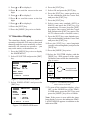
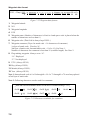
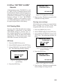
Display
unit
Standard
Steering
0.9 m
0.7 m
TABLE OF CONTENTS
FOREWORD ...................................... v
1. OPERATIONAL
OVERVIEW
1.1 System Configuration .................... 1-1
1.2 Control Description ....................... 1-2
1.3 Turning On and Off the Power....... 1-3
1.4 Adjusting Display Dimmer and
Contrast .......................................... 1-3
1.5 Display Modes ............................... 1-4
1.6 Basic Menu Operation ................... 1-7
1.7 Simulator Display .......................... 1-8
2. PLOTTER DISPLAY
OVERVIEW
2.1 Enlarging/Shrinking the Display.... 2-1
2.2 Shifting the Cursor ......................... 2-1
2.3 Shifting the Display ....................... 2-2
2.4 Centering Own Ship’s Position ...... 2-2
2.5 Changing Track Plotting Interval,
Stopping Plotting of Track ............. 2-2
2.6 Erasing Track ................................. 2-3
3. WAYPOINTS (MARKS)
3.1 Entering Waypoints ........................ 3-1
3.2 Entering the MOB Mark ................ 3-3
3.3 Displaying Waypoint Name ........... 3-3
3.4 Editing Waypoints on the
WYPTS/MARKS List ................... 3-4
3.5 Deleting Waypoints ........................ 3-4
4. ROUTES
4.1 Creating a Route ............................ 4-1
4.2 Editing a Route .............................. 4-2
4.3 Deleting a Route ............................ 4-4
5. SETTING, CANCELLING
DESTINATION
5.1 Setting Destination by Cursor ........ 5-1
5.2 Setting Destination by Waypoint ... 5-1
5.3 Setting Route as Destination .......... 5-2
5.4 Canceling Destination .................... 5-2
6. ALARMS
6.1 Arrival Alarm, Anchor Watch
Alarm ............................................. 6-1
6.2 XTE (Cross Track Error) Alarm .... 6-3
6.3 Speed Alarm................................... 6-3
7. OTHER FUNCTIONS
7.1 Calculating Range, Bearing
and TTG ......................................... 7-1
7.2 DGPS Setup ................................... 7-2
7.3 Bearing Reference ......................... 7-2
7.4 Magnetic Variation ......................... 7-3
7.5 Geodetic Chart System .................. 7-3
7.6 Units of Measurement .................... 7-4
7.7 Displaying Position in LOPs.......... 7-4
7.8 Time Difference (using local time) 7-4
7.9 GPS Setup ...................................... 7-5
7.10 Uploading, Downloading
Waypoint, Route Data .................. 7-6
8. MAINTENANCE &
TROUBLESHOOTING
8.1 Maintenance ................................... 8-1
8.2 Displaying the Message Board ...... 8-1
8.3 Displaying the GPS
Satellite Monitor Display ............... 8-1
8.4 Self Test ......................................... 8-2
8.5 When “BATTERY ALARM!”
Appears .......................................... 8-3
8.6 Clearing Data ................................. 8-3
iii
9. INSTALLATION
9.1 Installation of Display Unit............ 9-1
9.2 Installation of Antenna Unit ........... 9-1
9.3 Wiring ............................................ 9-2
9.4 Initial Settings ................................ 9-3
APPENDIX
SPECIFICATIONS ............................. A-1
EQUIPMENT LISTS .......................... A-3
GEODETIC CHART LIST ................. A-4
DGPS REFERENCE STATIONS ....... A-5
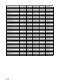
LORAN C CHAINS .......................... A-11
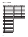
DECCA CHAINS ............................. A-12
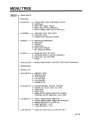
MENU TREE.................................... A-13
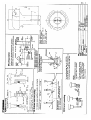
OUTLINE DRAWINGS .............. D-1
SCHEMATIC DIAGRAMS ........ S-1
iv
FOREWORD
A Word to GP-30/35 Owners
Features
Congratulations on your choice of the
FURUNO GP-30/35 GPS Navigator. We are
confident you will see why the FURUNO
name has become synonymous with quality
and reliability.
The GP-30/35 GPS Navigator is a totally
integrated GPS receiver and video plotter,
and consists of a display unit and an antenna
unit. The high sensitivity receiver tracks up
to eight satellites simultaneously. An 8-state
Kalman filter ensures optimum accuracy in
determination of vessel position, course and
speed.
For over 40 years FURUNO Electric Company has enjoyed an enviable reputation for
innovative and dependable marine electronics equipment. This dedication to excellence
is furthered by our extensive global network
of agents and dealers.
Your navigator is designed and constructed
to meet the rigorous demands of the marine
environment. However, no machine can perform its intended function unless installed,
operated and maintained properly. Please
carefully read and follow the recommended
procedures for installation, operation, and
maintenance.
We would appreciate hearing from you, the
end-user, about whether we are achieving
our purposes.
Thank you for considering and purchasing
FURUNO equipment.
The main features of the GP-30/35 are
• GP-35 has a built-in DGPS beacon receiver which improves position accuracy.
• A DGPS beacon receiver may be connected to the GP-30.
• Comprehensive navigation data displays
• Storage for 350 waypoints and 30 routes
• Alarms: Arrival, Anchor Watch, Cross
Track Error and Ship’s Speed
• Man overboard feature records latitude
and longitude or LOP (Loran C or Decca)
coordinates at time of man overboard and
provides continuous updates of range and
bearing when navigating to the MOB
position.
• Menu-driven operation
• Bright 95 x 60 mm LCD with adjustable
contrast and brilliance
• Power consumption is a low 3 W.
• Provision for connection of autopilot (option) – steering data output to autopilot
• Unique “Highway” display provides a
graphic presentation of ship’s progress toward a waypoint.
• Own ship’s position may be shown in latitude and longitude or LOP (Loran C or
Decca).
• Waypoint and route data can be uploaded
from a PC or downloaded to a PC.
v
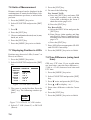
1.2 Control Description
Cursor Pad
• Shifts cursor and display.
• Selects items on menus.
One pressing: Zoom, centering.
Two pressings: Opens menu.
MENU
ENT
Selects display mode.
DISP
GOTO
MARK
MOB
DIM
PWR
Figure 1-2 Control panel
1-2
Registers items on menus.
Sets/cancels destination.
Inscribes mark, MOB mark
on the display.
Long press: Turns power
on/off.
Touch and release: Opens
the display for adjustment of
dimmer and contrast.
1.3 Turning On and Off the
Power
Turning on the power
Press and hold down the [DIM/PWR] key.
The unit beeps and then starts up with the
last-used display mode.
The GP-30/35 takes about two minutes to
find its position when turned on for the very
first time. This is because the default position is San Francisco, USA. If you want to
lessen the time needed to find position you
may enter your position manually on the
SIMULATOR screen of the SYSTEM
SETUP MENU, referring to 1.7 Simulator
Display on page 1-8. Thereafter it takes
about 20 seconds to find position each time
the power is turned on.
If position could not be found, “GPS NO
FIX” appears at the center of the display.
When the satellite signal is being received
normally, the GP-30/35 displays various abbreviations at the top left-hand corner of the
display which show receiver status. Table
1-1 shows these abbreviations and their
meanings.
Turning off the power
Press and hold down the [DIM/PWR] key
until the screen goes blank.
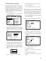
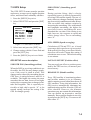
1.4 Adjusting Display Dimmer
and Contrast
1. Press the [DIM/PWR] key. The display
shown in Figure 1-3 appears.
DIMMER (1~8)
▼
▲ 4
CONTRAST (0~63)
t
s 41
EXIT:[ENT]
Figure 1-3 Screen for adjustment of
display dimmer and contrast
2. To adjust the dimmer, press ▲ or ▼. Current setting is shown to the right of “▲”.
3. To adjust the contrast, press t or s.
Current setting is shown to the right of
“s”.
4. Press the [ENT] key to finish.
Table 1-1 Display abbreviations
Indication
Meaning
2D
Normal 2D GPS position fix
DOP
GPS position fix with DOP
more than 4
3D
Normal 3D GPS position fix
DOP
DOP (DOP more than 6)
D2D
Normal differential GPS
position fix
DOP
Differential GPS position
fixwith DOP more than 4
D3D
Normal 3D differential GPS
position fix
DOP
Differential GPS position fix
with DOP more than 6
SIM
Simulation mode.
1-3
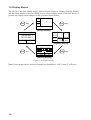
1.5 Display Modes
The GP-30/35 has four display modes: Plotter Display, Highway Display, Steering Display,
and Nav Data Display. Press the [DISP] key to select a display mode. Each time the key is
pressed, the display mode changes in the sequence shown below.
2D
n
[5 m]
x
X
CSE:
7°
SPD: k
0.0 t
DISP key
DISP key
34°44.000N 135°21.000E
[Plotter Display]
2D
12—DEC—97 15:37:40
34° 44. 000’
135° 21. 000’
SPD: 6.5 kt
CSE:
BRG ---°
N
CSE
E
N
n
RNG --- m
7°
SPD 6.5
k
t
0.5
XTE:
0.5
n
0.05 m
[Highway Display]
[Nav Data Display]
2D MAG
300
DISP key
7°
SPD:
RNG:
TTG:
05:32
330
N
6.5
kt
--.- nm
1H30M
30
60
CSE:
BRG:
E
20°
DISP key
---°
ETA: 12:30
[Steering Display]
Figure 1-4 Display modes
Note: Position data can be shown in latitude and longitude or LOP (Loran C or Decca).
1-4
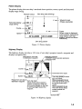
Steering Display
The steering display provides steering information such as range, bearing and ETA to destination, course, and speed.
Receiver status
Bearing reference (magnetic)
Time
2D
W
I
300 330
I
04:32
CURSOR
MAG
I
I
I
I
N
30
I
I
I
E
60
I
I
I
Bearing from own ship
to destination
Bearing scale
I
Own ship mark
Speed
Range from own ship to
destination
Time-To-Go to
destination
SPD:
RNG:
TTG:
12.5 kt
9.0
nm
CSE:
354°
Course
BRG:
60°
Bearing
ETA:
12:30
Estimated Time of
Arrival at destination
1H30M
Figure 1-7 Steering display
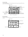
Nav Data Display
The Nav Data display shows position in latitude and longitude (or TDs), course, speed, date
and time.
Receiver status
2D
34°44.000'
135°21.000'
Speed
SPD:
12.5
kt
CSE:
7°
Figure 1-8 Nav data display
1-6
Date and time
12–DEC–97 16 :44 :15
N
Position in latitude
and longitude
E
Course
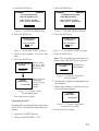
1.6 Basic Menu Operation
Most operations of the GP-30/35 are carried
out through the menu. Below is a quick introduction to how to select a menu and
change menu settings. If you get lost in operation, press the [MENU] key to return to
the MAIN MENU. A complete menu tree
appears on page A-12.
1. Press the [MENU] key twice to display
the MAIN MENU.
MESSAGES
SATELLITE
GPS SETUP
SYS SETUP
I/O SETUP
LOP SETUP
Figure 1-9 MAIN MENU
2. Operate the Cursor Pad to select a menu
and press the [ENT] key. For example,
select PLOTTER and press the [ENT]
key.
DISTANCE
0.10 nm
MAG
AUTO E16°
DSP GOTO
TRACK MEMORY USED
7. Press the [MENU] key twice to finish.
How to enter numeric, character data
In some instances it is necessary to enter numeric or character data. The example below
shows how to enter a time difference of –
6:30, to use local time instead of UTC time.
2. Select SYS SETUP and press the [ENT]
key.
SYSTEM SETUP
DATUM
: WGS84
UNITS
: nm, kt
TIME DIFF : +00 : 00
SELF TEST?
SIMULATOR?
11–DEC–97
14: 20: 25
Figure 1-12 SYSTEM SETUP menu
3. Press ▼ to select the TIME DIFF line.
PLOTTER SETUP
TRACK REC :
INTERVAL :
BRG. REF. :
MAG. VAR. :
WYPT NAME :
6. Press the [ENT] key.
1. Press the [MENU] key twice to display
the MAIN MENU.
MAIN MENU
WAYPOINTS
ROUTES
PLOTTER
ALARMS
ERASE
D-GPS
CALCULATE
5. Press ▲ or ▼ to select option desired.
1%
Figure 1-10 PLOTTER SETUP menu
3. Press ▲ or ▼ to select menu item. For
example, select the TRACK REC line.
4. Press the [ENT] key. A window showing options appears. (The figure below
shows the options available for TRACK
REC.)
OFF
DISTANCE
AUTO
Figure 1-11 Options of TRACK REC
4. Press the [ENT] key. A cursor circumscribes “+”. The cursor selects the data
to change.
SYSTEM SETUP
DATUM
: WGS84
UNITS
: nm, kt
TIME DIFF : +00 : 00
SELF TEST?
SIMULATOR?
11–DEC–97
14: 20: 25
Figure 1-13 SYSTEM SETUP menu,
TIME DIFF line selected
5. Press ▲ to display “–”.
6. Press s to send the cursor to the next
digit.
7. Press ▲ or ▼ to display 0.
8. Press s to send the cursor to the next
digit.
1-7
9. Press ▲ or ▼ to display 6.
4. Press the [ENT] key.
10.Press s to send the cursor to the next
digit.
5. Select ON and press the [ENT] key.
11. Press ▲ or ▼ to display 3.
12.Press s to send the cursor to the last
digit.
13.Press ▲ or ▼ to display 0.
14.Press the [ENT] key.
15.Press the [MENU] key twice to finish.
1.7 Simulator Display
The simulator display provides simulated
operation of this unit. You may set the speed
manually and the course manually or automatically. All controls are operative – you
may enter marks, set destination, etc.
1. Press the [MENU] key twice to display
the MAIN MENU.
2. Select SYS SETUP and press the [ENT]
key.
SYSTEM SETUP
DATUM
: WGS84
UNITS
: nm, kt
TIME DIFF : +00 : 00
14: 20: 25
3. Select SIMULATOR? and press the
[ENT] key.
SIMULATOR
MODE
: OFF
SPEED
: 20 kt
COURSE : AUTO
: 38°00'N
: 123°00'W
11–DEC–97
14: 20: 25
Figure 1-15 SIMULATOR menu
1-8
8. Select course entry method (AUTO or
MANU) and press the [ENT] key. For
manual entry of course, press the [ENT]
key again, enter course with the Cursor
Pad, and press the [ENT] key again. (The
AUTO course tracks a circular course.)
9. Press the [ENT] key, enter latitude (usually current latitude) with the Cursor Pad,
and press the [ENT] key.
10.Press the [ENT] key, enter longitude
(usually current longitude), and press the
[ENT] key.
11. Press the [MENU] key twice.
12.Select the PLOTTER display with the
[DISP] key. SIM appears at the upper
left-hand corner when the simulator display is active.
SIM
n
m ]
[ 40
CSE:
Course traced
in AUTO course
SPD:
Figure 1-14 SYSTEM SETUP menu
LAT
LON
7. Press the [ENT] key.
82°
SELF TEST?
SIMULATOR?
11–DEC–97
6. Press the [ENT] key, enter speed to use
for the simulation with the Cursor Pad,
and press the [ENT] key.
9.0
k
t
34°44.000N 135°21.000E
Figure 1-16 Simulator display,
auto course selected
13.To turn off the simulator display, select
OFF on the MODE line of the SIMULATOR menu, press the [ENT] key, and
press the [MENU] key twice to finish.
Note: If the power is reset while the simulator display is in use, the indication SIMULATION MODE appears in addition to the
indication SIM.
2. PLOTTER DISPLAY OVERVIEW
2.1 Enlarging/Shrinking the
Display
You may enlarge and shrink the display on
the Plotter and Highway displays. The horizontal range in the Plotter display is available among 0.2, 0.5, 1, 2, 5, 10, 20, 40, 80,
160 and 320 nautical miles. The horizontal
range in the Highway display is available
among 0.2, 0.4, 0.8, 1, 2, 4, 8, 16 nautical
miles.
1. Press the [MENU] key. ZOOM IN/OUT?
appears in reverse video.
ZOOM IN/OUT?
SHIP TO CENTER?
Quit?
PRESS [MENU] TO SEE
THE MAIN MENU.
Figure 2-1 Zoom, ship centering window
Note: The prompt SHIP TO CENTER?
does not appear in the Highway display
mode.
2. Press the [ENT] key. The window
changes as below.
2.2 Shifting the Cursor
Operate the Cursor Pad to shift the cursor.
The cursor moves in the direction of the arrow or diagonal pressed on the Cursor Pad.
Cursor state and data
Cursor state determines what data is shown
on the display.
Cursor turned on
Cursor position is displayed in latitude and
longitude or LOPs (depending on menu setting) at the bottom of the Plotter display
when the cursor is on. The range and bearing from own ship to the cursor appear at
the left-hand side of the display.
Bearing from own
ship to cursor
Cursor
2D
[ 40
n
m ]
BRG: +
82°
RNG: +
9.0 mn
+ 34°44.000N 135°21.000E
ZOOM
▲ OUT
20
▼
n
m
IN
EXIT:
[ENT]
Figure 2-2 Zoom window
3. Press ▲ (enlarge) or ▼ (shrink) to select
range desired.
Cursor mark
Cursor position in
latitude and longitude
Range from own ship to cursor
Figure 2-3 Data displayed on the Plotter
display when the cursor in on
Cursor turned off
The cursor is erased when there is no Cursor Pad operation for about five seconds.
Ship’s position, speed and course appear at
the left side of the Plotter display when the
cursor is off.
4. Press the [ENT] key to finish.
2-1
Own ship’s position
(Blinking)
Course
2D
n
m
[ 40
]
CSE:
7°
SPD:
9.0
k
t
34°44.000N 135°21.000E
Speed
Own ship’s position in
latitude and longitude
Figure 2-4 Data displayed on the Plotter
display when the cursor is turned off
2.3 Shifting the Display
The display can be shifted on the Plotter display. Operate the Cursor Pad to place the
cursor at an edge of the screen. The display
shifts in the direction opposite to Cursor Pad
operation.
When own ship tracks off the display it is
automatically returned to the screen center.
2.5 Changing Track Plotting
Interval, Stopping Plotting
of Track
In drawing track, first the ship’s position (fed
from the GPS receiver) is stored into the
memory at an interval of distance or automatic recording. For distance, a shorter interval provides better reconstruction of the
track, but the storage time of the track is reduced. When the track memory becomes
full, the oldest track is erased to make room
for the latest.
1. Press the [MENU] key twice.
MAIN MENU
WAYPOINTS
ROUTES
PLOTTER
ALARMS
ERASE
D-GPS
CALCULATE
MESSAGES
SATELLITE
GPS SETUP
SYS SETUP
I/O SETUP
LOP SETUP
Figure 2-5 MAIN MENU
2. Select PLOTTER.
3. Press the [ENT] key.
PLOTTER SETUP
2.4 Centering Own Ship’s
Position
TRACK REC :
INTERVAL :
BRG. REF. :
MAG. VAR. :
WYPT NAME :
DISTANCE
0.10 nm
MAG
AUTO E16°
DSP GOTO
1. Press the [MENU] key.
2. Select SHIP TO CENTER?.
3. Press the [ENT] key.
2-2
TRACK MEMORY USED
1%
Figure 2-6 Plotter setup menu
4. The cursor should be on the TRACK
REC line. Press the [ENT] key. The track
recording method selection window appears.
OFF
DISTANCE
AUTO
Figure 2-7 Track recording
method selection window
5. Select OFF, DISTANCE or AUTO and
then press the [ENT] key.
OFF: Track is neither recorded or plotted. This setting is useful when you do
not need to record track, for example,
when returning to port.
DISTANCE: Track is recorded and plotted at the distance interval set.
AUTO: Plotting and recording interval
changes with chart scale selected.
If you selected DISTANCE, enter the recording interval as follows:
a) Press the [ENT] key.
b) Press t or s to select digit to change.
c) Press ▲ or ▼ to change value.
d) Press the [ENT] key after setting.
6. Press the [MENU] key twice to finish.
2.6 Erasing Track
All track can be erased. Track cannot be restored once erased. Be absolutely sure you
want to erase all track.
1. Press the [MENU] key twice.
2. Select ERASE and press the [ENT] key.
The ERASE menu appears.
ERASE
WAYPOINTS/MARKS?
ROUTES?
TRACK?
GPS DATA?
MENU SETTINGS?
ALL BACKUP DATA?
Figure 2-8 ERASE menu
3. Select TRACK? and press the [ENT] key.
The message shown in Figure 2-9 appears.
ERASE TRACK.
ARE YOU SURE?
YES
NO
Figure 2-9 Prompt for erasure of track
4. Press the [ENT] key to erase all track.
5. Press the [MENU] key twice to finish.
2-3
3. WAYPOINTS (MARKS)
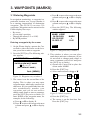
3.1 Entering Waypoints
In navigation terminology a waypoint is a
particular location on a voyage whether it
be a starting, intermediate or destination
waypoint. The GP-30/35 can store 350
waypoints. Waypoints can be entered on the
Plotter display four ways:
• By cursor
• At own ship’s position
• Through the menu (L/L or LOP)
• By MOB position
c) Press s to move the cursor to the next
column and press ▲ or ▼ to display
B.
d) Press s to move the cursor to the next
column and press ▲ or ▼ to display
E.
e) Press the [ENT] key. The following
window appears.
NAME: KOBE
34°39.836'N
135°12.059'E
12–DEC–97
MARK
+
11:25
Entering a waypoint by the cursor
1. On the Plotter display, operate the Cursor Pad to place the cursor on the location you want to make a waypoint.
2. Press the [ENT] key. The following window appears.
CURSOR POS. → WYPT
ENTER A NEW WYPT NAME.
001–––?
( 001: DEFAULT NAME )
Quit : [MENU]
Exit?
Figure 3-2 Waypoint entry window-2
4. This window is where you can select
mark shape and enter a comment. (If you
do not need to change mark shape or
enter a comment, select Exit? and press
the [ENT] key to finish.)
a) Operate the Cursor Pad to place the
cursor under MARK.
b) Press the [ENT] key.
c) Select mark desired with ▲ or ▼.
Figure 3-1 Waypoint entry window-1
3. The cursor is on the second line of the
display. This is where you may enter
waypoint name, which may consist of six
characters. (If you would rather have the
unit automatically number your
waypoints, and you do not need to
change mark shape or enter a comment,
press the [ENT] key twice to finish.) To
enter KOBE as the waypoint name, for
example, do the following:
a) Press ▲ or ▼ to display K.
b) Press s to move the cursor to the next
column and press ▲ or ▼ to display
O.
X
H
+
I
Figure 3-3 Mark sequence
d) Press the [ENT] key.
e) The cursor is on the date/time line.
Press the [ENT] key.
3-1
f) Enter a comment (max. sixteen characters) with the Cursor Pad and press
the [ENT] key. To create a space select “blank” character. To remove all
characters which follow the cursor,
select the underline.
g) Press the [ENT] key.
h) Press the [ENT] key again to finish.
Entering a waypoint through the
menu
1. Press the [MENU] key twice.
2. Select WAYPOINTS.
3. Press the [ENT] key. The WYPTS/
MARKS menu appears.
WYPTS/MARKS
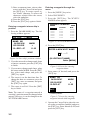
Entering a waypoint at own ship’s
position
1. Press the [MARK/MOB] key. The following window appears.
GPS POS. → MARK
NAME: 001
34°39.836’N
135°12.059’E
12—DEC—97
Exit?
[NEW?]
START
------------------------------------
CURSOR
-------------------------------------
MOB
-------------------------------------------
Figure 3-5 WYPTS/MARKS menu
MARK
+
11:25
4. Press the [ENT] key.
ENTER A NEW WYPT NAME.
MOB?
Figure 3-4 Own ship’s position window
2. If you do not need to change mark shape
or enter a comment, press the [ENT] key
to finish.
3. If you want to change mark shape, place
the cursor under MARK. Press the [ENT]
key, select mark shape, and press the
[ENT] key again.
001---?
(001:DEFAULT NAME)
Quite: [MENU]
Figure 3-6 Screen for entering
waypoint name
5. Enter name (if desired) and press the
[ENT] key.
4. The cursor is on the date/time line. To
change the date to a comment, press the
[ENT] key, enter a comment, and press
the [ENT] key again.
NAME: 001
34°39.836'N*
135°12.059'E*
12–DEC–97
5. The cursor is on Exit?. Press the [ENT]
key to finish.
Exit?
Note: The name of a waypoint entered at
own ship’s position cannot be changed when
entered. However, it can be changed on the
WYPTS/MARKS menu.
MARK
+
11:25
* Present position
Figure 3-7 Screen for entering
waypoint latitude and longitude
6. Operate the Cursor Pad to place the cursor on the second line (latitude) and press
the [ENT] key. Enter latitude (LOP) and
press the [ENT] key.
3-2
7. Press the [ENT] key, enter longitude
(LOP) in similar fashion and press the
[ENT] key.
3. Press the [ENT] key.
SAVED TO MOB.
GO TO MOB ?
Note: To enter position by LOPs, see
“7.8 Displaying Position in LOPs.”
ARE YOU SURE?
YES
8. To change mark shape, press the [ENT]
key, select mark desired and press the
[ENT] key.
NO
Figure 3-9 MOB window-2
9. To change date and time to the comment
of your choice, press the [ENT] key, enter comment, and press the [ENT] key
again.
4. To set MOB position as destination, press
the [ENT] key. Then, the Plotter display
marks MOB position.
10.The cursor is on Exit?. Press the [ENT]
key.
Note: Selecting “NO” at step 4 saves the
position as a waypoint.
MOB position set
as destination
11. Press the [MENU] key twice to finish.
2D
n
m
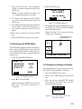
3.2 Entering the MOB Mark
[ 40
The MOB mark denotes man overboard position. Only one MOB mark may be entered.
Each time the MOB mark is entered the previous MOB mark and its position data are
written over.
BRG:
1. Press the [MARK/MOB] key.
NAME: 001
34°44.000'N
135°21.000'E
12–DEC–97
Exit?
MARK
x
11:25
MOB?
Figure 3-8 MOB window
2. Press s to select MOB?.
Note: Pressing the [ENT] key instead of
sat step 2 saves the position as a
waypoint.
]
MOB
72°
RNG:
54.5 mn
34°44.000N 135°21.000E
Figure 3-10 MOB set as destination
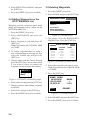
3.3 Displaying Waypoint Name
You may display all waypoint names or only
the GOTO waypoint name as follows:
1. Press the [MENU] key twice.
2. Select PLOTTER and press the [ENT]
key.
3. Place the cursor on the WYPT NAME
line and press the [ENT] key. The following window appears.
DSP GOTO
DSP ALL
Figure 3-11 DSP GOTO, DSP ALL
selection window
3-3
4. Select DSP GOTO or DSP ALL and press
the [ENT] key.
3.5 Deleting Waypoints
5. Press the [MENU] key twice to finish.
1. Press the [MENU] key twice.
2. Select ERASE and press the [ENT] key.
3.4 Editing Waypoints on the
WYPTS/MARKS List
Waypoint position, waypoint name, mark
shape and comment can be edited on the
WYPTS/MARKS List.
ERASE
WAYPOINTS/MARKS?
ROUTES?
TRACK?
GPS DATA?
MENU SETTINGS?
ALL BACKUP DATA?
1. Press the [MENU] key twice.
2. Select WAYPOINTS and press the
[ENT] key.
3. Select waypoint to edit and press the
[ENT] key.
Note: You cannot edit CURSOR, MOB
or START.
4. To change waypoint name or create a
new waypoint from an existing one, first
select the NAME line and press the
[ENT] key.
5. Change name with the Cursor Pad and
press the [ENT] key. You are then asked
if you want to create or rename the
waypoint, or quit (escape) this display.
CREATE?
RENAME?
Quit?
Figure 3-12 CREATE, RENAME prompt
6. Select objective and press the [ENT] key.
7. Change position, mark shape, comment
as desired.
Figure 3-13 ERASE menu
3. The cursor is on the WAYPOINTS/
MARKS? line. Press the [ENT] key.
ERASE WP/MRK
[ALL?]
MOB
----------------------------------------
CURSOR
START
-------------------------------
KOBE
--------------------------------------
Figure 3-14 ERASE WP/MRK display
4. Select the waypoint you want to erase.
Note: You cannot erase CURSOR, MOB
or START.
5. Press the [ENT] key.
NAME: KOBE
34°39.836'N
135°12.059'E
12–DEC–97
Quit?
MARK
+
11:25
ERASE?
8. Select Exit? and press the [ENT] key.
9. Press the [MENU] key twice to finish.
Figure 3-15 ERASE prompt
6. Select ERASE? and press the [ENT] key.
7. Press the [MENU] key twice to finish.
3-4
4. ROUTES
In many cases a trip from one place to another involves several course changes, requiring a series of route points (waypoints)
which you navigate to, one after another. The
sequence of waypoints leading to the ultimate destination is called a route. The GP30/35 can automatically advance to the next
waypoint on a route, so you do not have to
change the destination waypoint repeatedly.
Registering a route
The procedure which follows describes how
to create a route from two waypoints in Japan, KOBE and OSAKA.
1. Press the [MENU] key twice.
2. Select ROUTES.
3. Press the [ENT] key. The screen shown
in Figure 4-2 appears.
ROUTES
4.1 Creating a Route
You can store up to 30 routes and each route
may contain up to 30 waypoints. The unit
numbers routes from 01 to 30. The easiest
way to create a route is to enter appropriate
waypoints beforehand and select them from
the waypoint list. However, you may also
enter waypoints while creating a route.
Note: Be sure to record all important routes
in a separate log. This unit is not a fail-safe
record keeping device.
WAYPOINT
(Intermediate point)
[NEW?]
––
––
––
––
––
––––––––––––––––
––––––––––––––––
––––––––––––––––
––––––––––––––––
––––––––––––––––
Figure 4-2 Routes menu
4. Press the [ENT] key. The screen shown
in Figure 4-3 appears.
ROUTE-01
WAYPOINT
(Arrival point)
WAYPOINT
(Intermediate point)
WAYPOINT
(Starting point)
NO
WAYPOINT
(Intermediate point)
CMNT:
01.
02.
03.
04.
05.
06.
Exit?
EMPTY ROUTE
––––––
––––––
––––––
––––––
––––––
––––––
Figure 4-1 Sample route
Figure 4-3 Screen for entering route
5. Press the [ENT] key.
6. Press ▲ or ▼ to display starting
waypoint. (In the example, KOBE.)
7. Press the [ENT] key twice. The cursor
moves to the head of next line.
8. Repeat steps 6 and 7 until you have entered all intermediate waypoints desired.
9. Finally, select arrival point. (In the example, OSAKA.)
4-1
10.Select Exit?.
11. Press the [ENT] key to register the route.
Then, the display shows the names of
starting and arrival waypoints next to
route number.
ROUTES
NO
[NEW?]
01
––
––
––
––
KOBE → OSAKA
––––––––––––––––
––––––––––––––––
––––––––––––––––
––––––––––––––––
Figure 4-4 ROUTES list
12.Press the [MENU] key twice to finish.
4.2 Editing a Route
Replacing a waypoint in a route
1. Press the [MENU] key twice.
2. Select ROUTES and press the [ENT]
key.
3. Select the route to edit.
4. Press the [ENT] key.
5. Place the cursor on the waypoint to replace.
6. Press the [ENT] key. The following window appears.
CHANGE?
REMOVE?
INSERT?
SKIP?
Quit?
NAME: 001
34°39.836'N
135°12.059'E
12–DEC–97
MARK
+
11:25
Exit?
Figure 4-6 Waypoint screen
8. Press the [ENT] key. Press ▲ or ▼ to
select a waypoint.
9. Press the [ENT] key.
Note: If the name selected at step 9 has
not been used, the window shown in
Figure 4-7 appears. Select CREATE? or
RENAME? as appropriate and press the
[ENT] key.
CREATE?
RENAME?
Quit?
Figure 4-7 CREATE, RENAME prompt
10.Select Exit?.
11. Press the [ENT] key.
12.Press the [MENU] key twice to finish.
Permanently deleting a waypoint
from a route
1. Press the [MENU] key twice.
2. Select ROUTES and press the [ENT]
key.
3. Select the route from the ROUTES list.
4. Press the [ENT] key.
5. Select the waypoint you want to delete.
6. Press the [ENT] key.
Figure 4-5 Window for editing
waypoint in route
7. CHANGE? is selected; press the [ENT]
key.
7. Select REMOVE?.
8. Press the [ENT] key.
9. Select Exit? and press the [ENT] key.
10.Press the [MENU] key twice to finish.
4-2
Inserting a waypoint in a route
To insert a waypoint in a route, do the following:
1. Press the [MENU] key twice.
2. Select ROUTES and press the [ENT]
key.
Temporarily deselecting a waypoint
in a route
You can temporarily deselect an unnecessary waypoint from a route. Using the route
created in Figure 4-9 as an example, deselect the 2nd intermediate waypoint.
[ROUTE 01]
Intermediate Point 2
(WPT 002)
3. Select the route from the ROUTES list.
4. Press the [ENT] key.
5. Select the waypoint which will come after waypoint to be inserted. In Figure 48, for example, if you want to insert a
waypoint between KOBE and 001, select 001.
ROUTE-01
CMNT:
01.
02.
03.
04.
05.
06.
Exit?
KOBE → OSAKA
KOBE
001
002
003
004
OSAKA
Figure 4-8 ROUTE screen
6. Press the [ENT] key.
OSAKA
(Arrival point)
Intermediate Point 1
(WPT 001)
KOBE
(Starting point)
Intermediate Point 1
(WPT 003)
Figure 4-9 Sample route
If you reconstruct the route without the 2nd
intermediate point it would look like Figure
4-10.
WPT 002
SKIP "002"
OSAKA
WPT 001
KOBE
WPT 003
Figure 4-10 Route in Figure 4-9
reconstructed without 2nd
intermediate waypoint
7. Select INSERT?.
1. Press the [MENU] key twice.
8. Press the [ENT] key.
2. Select ROUTES and press the [ENT]
key.
9. Press ▲ or ▼ to select waypoint.
10.Press the [ENT] key.
11. Select Exit? and press the [ENT] key.
12.Press the [MENU] key twice to finish.
3. Select a route from the ROUTES list, and
press the [ENT] key.
4. Place the cursor on the waypoint to skip.
5. Press the [ENT] key.
6. Select SKIP? and press the [ENT] key.
X appears to the left of the waypoint.
ROUTE-01
CMNT:
01.
02.
x 03.
04.
05.
06.
Exit?
KOBE → OSAKA
KOBE
001
002
003
004
OSAKA
Figure 4-11 ROUTE screen
4-3
7. Select Exit? and press the [ENT] key.
8. Press the [MENU] key twice to finish.
To restore a waypoint to a route, select
SKPoFF at step 6.
4.3 Deleting a Route
1. Press the [MENU] key twice.
2. Select ERASE and press the [ENT] key.
3. Select ROUTES? and press the [ENT]
key.
4. Select the route you want delete. If you
want to delete all routes, select ALL?.
5. Press the [ENT] key. You are asked if
you are sure to delete the route.
ERASE ROUTE 01 ?
ARE YOU SURE?
YES
NO
Figure 4-12 ERASE ROUTE prompt
6. Press the [ENT] key again.
7. Press the [MENU] key twice to finish.
4-4
5. SETTING, CANCELLING DESTINATION
Destination can be set four ways: by cursor,
by waypoint, by route, and by MOB position. Destination cannot be set when there
is no GPS position data. When there is no
position data, the buzzer sounds and the message “GPS NO FIX” appears. Previous destination is cancelled whenever a destination
is newly set.
4. Place the cursor on the location desired
for destination.
5. Press the [ENT] key.
A dashed line connects own ship and the destination, which is marked with CURSOR
and an X, as shown in Figure 5-3.
CURSOR
x
5.1 Setting Destination by
Cursor
1. Press the [GOTO] key to display the
GOTO window.
GOTO
5.2 Setting Destination by
Waypoint
WAYPOINT?
ROUTE?
CURSOR?
OFF?
Quit?
1. Press the [GOTO] key.
2. Select WAYPOINT?.
Figure 5-1 GOTO window
2. Select CURSOR?.
Cursor appears with "?".
2D
n
m ]
3. Press the [ENT] key. The GOTO WYPT
list appears.
SELECT GOTO WYPT
3. Press the [ENT] key.
[ 40
Figure 5-3 Destination set by cursor
?
[NEW?]
MOB
----------------------------------
CURSOR
OSAKA
---------------------------------
KOBE
START
----------------------------------
+GOTO?
BRG: +
72°
RNG: +
54.5 mn
34°44.000N 135°21.000E
Figure 5-2 Cursor appearance
when setting destination by cursor
Figure 5-4 GOTO WYPT list
4. Select a waypoint.
5. Press the [ENT] key.
Own ship’s position becomes starting point
and a dotted line runs between it and the
waypoint selected.
5-1
5.3 Setting Route as
Destination
5.4 Canceling Destination
1. Press the [GOTO] key.
1. Press the [GOTO] key.
2. Select ROUTE?.
2. Select OFF?.
3. Press the [ENT] key.
3. Press the [ENT] key.
You can cancel destination as follows:
SELECT GOTO ROUTE
NO
01
––
––
––
––
––
[NEW?]
KOBE → OSAKA
––––––––––––––––
––––––––––––––––
––––––––––––––––
––––––––––––––––
––––––––––––––––
Figure 5-5 GOTO ROUTE list
4. Select a route.
5. Press the [ENT] key. The following window appears.
FORWARD?
REVERSE?
Figure 5-7 FORWARD, REVERSE prompt
6. Select FORWARD? or REVERSE?, the
order in which to traverse the route
waypoints, and press the [ENT] key.
[ROUTE 01]
Intermediate Point 2
(WPT 002)
Intermediate Point 1
(WPT 001)
FORWARD
KOBE
(Starting point)
OSAKA
(Arrival point)
REVERSE
Intermediate Point 1
(WPT 003)
Figure 5-8 Meaning of forward and reverse
Current position becomes starting point. A
dotted line runs between all route points.
5-2
6. ALARMS
There are four alarm conditions which generate both audible and visual alarms: Arrival
alarm, Anchor watch alarm, Speed alarm,
and XTE (Cross Track Error) alarm.
When an alarm setting is violated, the buzzer
sounds, and the name of the offending alarm
and the alarm icon appear on the display.
You can silence the buzzer and remove the
alarm name indication by pressing any key
but the alarm icon remains on the screen until
the reason for the alarm is cleared.
You can also see which alarm(s) is sounding by displaying the MESSAGE board. The
keying sequence is [MENU] (twice), select
MESSAGES and press the [ENT] key. (The
message board is explained in 8.2 Displaying the Message Board.)
Alarm
2D
XTE ALARM!
n
m
[ 40
You may activate the arrival alarm or the
anchor watch alarm; they cannot be activated
together.
Arrival alarm
The arrival alarm informs you that own ship
is approaching a destination waypoint. The
area that defines an arrival zone is that of a
circle which you approach from the outside
of the circle. The alarm will be released if
own ship goes out of the circle.
Alarm
setting
Own ship’s
position
!
: Alarm
]
Alarm
icon
CSE:
82°
SPD:
9.0
6.1 Arrival Alarm, Anchor
Watch Alarm
k
t
34°44.000N 135°21.000E
Figure 6-1 Location of alarm
message and icon
Destination
waypoint
Figure 6-2 How the arrival alarm works
1. Press the [MENU] key twice.
2. Select ALARMS.
3. Press the [ENT] key. The ALARMS
menu appears.
ALARMS
ARV/ANC : ARV
XTE
: OFF
SPEED : OFF
0.30 nm
0.50 nm
12.0 kt
ARV : ARRIVAL ALARM
ANC : ANCHOR WATCH ALARM
XTE : CROSS TRACK ERROR
Figure 6-3 ALARMS menu
6-1
4. The cursor is on the first line of the display. If ARV is already selected, press s
and [ENT], set the alarm range with the
Cursor Pad and then go to step 6. If ARV
is not selected, press the [ENT] key. The
display shown in Figure 6-4 appears. Select ARV and press the [ENT] key.
Anchor watch alarm
The anchor watch alarm sounds to warn you
that own ship is moving when it should be
at rest.
Alarm
setting
Own ship’s
position
OFF
ARV
ANC
Figure 6-4 Arrival/anchor window
5. Press the [ENT] key. Enter the alarm
range (0.01 – 99.99 nm) with the Cursor
Pad.
6. Press the [ENT] key.
7. Press the [MENU] key twice to finish.
When own ship nears the GOTO waypoint
by the range set here, the buzzer sounds and
the message ARV ALARM! appears.
To disable the alarm, select OFF at step 4.
Destination
waypoint
: Alarm
Figure 6-5 How the anchor watch
alarm works
Before setting the anchor watch alarm, set
present position as destination waypoint.
1. Press the [MENU] key twice.
2. Select ALARMS.
3. Press the [ENT] key.
4. If ANC is already selected, press s and
[ENT], set the alarm range with the Cursor Pad and then go to step 7. If ANC is
not selected, press the [ENT] key. The
display shown in Figure 6-4 appears.
Select ANC and press the [ENT] key.
5. Press the [ENT] key. Enter the alarm
range (0.01 – 99.99 nm) with the Cursor
Pad.
6. Press the [ENT] key.
7. Press the [MENU] key twice to finish.
When own ship drifts more than the range
set here, the buzzer sounds and the message
ANC ALARM! appears.
To disable the alarm, select OFF at step 4.
6-2
6.2 XTE (Cross Track Error)
Alarm
The XTE alarm warns you when own ship
is off its intended course.
6.3 Speed Alarm
The speed alarm sounds when ship’s speed
is higher (or lower) the alarm range set.
1. Press the [MENU] key twice.
2. Select ALARMS.
3. Press the [ENT] key.
Own ship’s
position
Alarm
setting
Destination
waypoint
4. Select the SPEED line and press the
[ENT] key.
5. Select BELOW or OVER.
: Alarm
Figure 6-6 How the XTE alarm works
1. Press the [MENU] key twice.
BELOW: Alarm sounds when speed
is lower than speed set.
OVER: Alarm sounds when speed is
higher than speed set.
2. Select ALARMS.
6. Press the [ENT] key twice.
3. Press the [ENT] key.
7. Enter speed with the Cursor Pad.
4. Select the XTE line and press the [ENT]
key.
8. Press the [ENT] key.
5. Select ON and press the [ENT] key.
When the speed alarm setting is violated,
the buzzer sounds and the message SPD
ALARM! appears.
6. Press the [ENT] key.
7. Enter alarm range with the Cursor Pad.
8. Press the [ENT] key.
9. Press the [MENU] key twice to finish.
To disable the alarm, select OFF at step 4.
9. Press the [MENU] key twice to finish.
When own ship strays from the intended
track by the range set here, the buzzer sounds
and message XTE ERROR! appears.
To disable the alarm, select OFF at step 5.
6-3
7. OTHER FUNCTIONS
7.1 Calculating Range, Bearing
and TTG
Range and bearing between two
waypoints
1. Press the [MENU] key twice.
2. Select CALCULATE.
3. Press the [ENT] key.
CALCULATION
MODE :
FROM :
TO
:
SPD :
WAYPOINTS
––––––
––––––
AUTO
TTG: ––H––M
RNG: –.–– nm
ETA: ––:––
BRG: –– °
Figure 7-1 CALCULATION menu
4. Press the [ENT] key to display the window shown in Figure 7-2.
WAYPOINTS
ROUTE
10.Select AUTO or MANU. AUTO uses
ship’s average speed; MANU is for
manual entry of speed.
11. Press the [ENT] key.
12.If you selected MANU, press the [ENT]
key again. Enter speed with the Cursor
Pad and press the [ENT] key.
Figure 7-4 shows what the display might
look like using waypoints KOBE and
OSAKA as the FROM and TO
waypoints, respectively.
Time-to-Go
Estimated Time of Arrival
CALCULATION
MODE :
FROM :
TO
:
SPD :
WAYPOINTS
KOBE
OSAKA
AUTO
TTG: 1H39M
RNG: 9.06 nm
ETA: 5:57
BRG: 80 °
Range
Bearing
Figure 7-4 Typical calculation display
13.Press the [MENU] key twice to finish.
Figure 7-2 WAYPOINTS, ROUTE prompt
5. Select WAYPOINTS and press the
[ENT] key.
6. Press the [ENT] key.
7. Enter the starting point and press the
[ENT] key.
8. Press the [ENT] key, enter the end point
and press the [ENT] key.
9. Press the [ENT] key. The window shown
in Figure 7-3 appears.
Range and bearing between first and
final waypoints of a route
You can easily find the range, bearing TTG
and ETA between the first point and final
point of a route.
1. Press the [MENU] key twice.
2. Select CALCULATE and press the
[ENT] key.
3. Press the [ENT] key.
4. Select ROUTE and press the [ENT] key.
AUTO
MANU
5. Press the [ENT] key.
6. Select route number.
Figure 7-3 AUTO, MANUAL prompt
7. Press the [ENT] key to display the window shown in Figure 7-3.
7-1
8. Select AUTO or MANU. AUTO uses
ship’s average speed to calculate timeto-go; MANU is for manual entry of
speed.
9. Press the [ENT] key. If you selected
AUTO no further operation is necessary.
For MANU, press the [ENT] key again.
Enter speed with the Cursor Pad and
press the [ENT] key.
Figure 7-5 shows what the display might
look like using Route-01 for an example.
Time-to-Go
Estimated Time of Arrival
CALCULATION
MODE :
NO. :
SPD
ROUTE
01 (WYPTS: 4)
KOBE → OSAKA
AUTO
:
TTG: 1H39M
RNG: 9.06 nm
ETA: --BRG: --- °
Range
Bearing
Figure 7-5 Typical calculation
display (route)
7.2 DGPS Setup
The GP-35 is equipped with a DGPS beacon receiver, and the GP-30 may be connected to a DGPS beacon receiver. Set up to
receive the DGPS beacon signal as follows:
4. Select INT for internal DGPS beacon receiver; EXT for external DGPS beacon
receiver. Press the [ENT] key.
5. The cursor is on the STATION line. Press
the [ENT] key.
6. Choose DGPS beacon station selection
method: AUTO 1, AUTO 2 or
MANUAL.
AUTO 1, AUTO 2: Automatically
search for nearest DGPS beacon station.
The GP-35 always searches for nearest
DPGS beacon station.
MANUAL: Manually enter DGPS beacon station specifications (on the RATE
and FREQ lines), referring to the DGPS
reference station list in the Appendix.
7. If you selected AUTO, no further operation is necessary; you may press the
[MENU] key twice to finish. For
MANUAL, the cursor is now on the
RATE line. Press the [ENT] key.
8. Select the transmission rate of the DGPS
beacon station nearest you, among 50,
100 or 200 bps. Press the [ENT] key.
9. The cursor is now on the FREQ line.
Press the [ENT] key.
10.Enter nearest DGPS beacon station’s frequency with the Cursor Pad.
11. Press the [ENT] key.
12.Press the [MENU] key twice to finish.
1. Press the [MENU] key twice.
2. Select D-GPS and press the [ENT] key.
D-GPS SETUP
BEACON
STATION
RATE
FREQ
: EXT
: MANUAL
: 200 BPS
: 310.0 kHz
BEACON STATION : GOOD
D-GPS DATA
: GOOD
SIG. S : 00.0 dB
SNR: 00.0 dB
Figure 7-6 D-GPS SETUP menu
3. Press the [ENT] key.
7.3 Bearing Reference
Ship's course and bearing to a waypoint may
be displayed in true or magnetic bearing.
Magnetic bearing is true bearing plus (or minus) earth’s magnetic deviation.
The default setting displays magnetic bearings.
1. Press the [MENU] key twice.
2. Select PLOTTER.
3. Press the [ENT] key.
7-2
PLOTTER SETUP
TRACK REC :
INTERVAL :
BRG. REF. :
MAG. VAR. :
WYPT NAME :
DISTANCE
0.10 nm
MAG
AUTO E16°
DSP GOTO
TRACK MEMORY USED
1%
Figure 7-7 PLOTTER SETUP menu
4. Select the BRG. REF. line.
5. Press the [ENT] key. The following window appears.
MAG
TRUE
Figure 7-8 Bearing reference window
6. Select MAG or TRUE.
7. Press the [ENT] key.
8. Press the [MENU] key twice to finish.
6. If you selected AUTO, no further operation is necessary, press the [MENU] key
twice to finish. For MANU, press the
[ENT] key and enter magnetic variation
as follows:
a) If necessary, change coordinate from
east to west or vice versa by pressing
▲ or ▼.
b) Enter variation in two digits with the
Cursor Pad, referring to a nautical
chart.
c) Press the [ENT] key.
d) Press the [MENU] key twice to finish.
7.5 Geodetic Chart System
Select the geodetic chart system you are using as follows:
1. Press the [MENU] key twice.
2. Select SYS SETUP and press the [ENT]
key.
SYSTEM SETUP
7.4 Magnetic Variation
The location of the magnetic north pole is
different from the geographical north pole.
This causes a difference between the true
and magnetic north direction. This difference
is called magnetic variation, and varies with
respect to the observation point on earth. The
GP-30/35 is preprogrammed with all the
earth's magnetic variation. However, you
may wish to enter variation manually to refine accuracy.
1. Press the [MENU] key twice.
2. Select PLOTTER and press the [ENT]
key.
3. Select the MAG. VAR. line.
4. Press the [ENT] key.
5. Select AUTO or MANU and press the
[ENT] key. For automatic magnetic
variation, current variation appears to the
right of AUTO.
DATUM
: WGS84
UNITS
: nm, kt
TIME DIFF : +00 : 00
SELF TEST?
SIMULATOR?
11–DEC–97
14: 20: 25
Figure 7-9 SYSTEM SETUP menu
3. Press the [ENT] key.
4. Select WGS84, WGS72 or OTHER and
press the [ENT] key.
5. If you selected WGS72 or WGS84, press
the [MENU] key twice to finish. For
OTHER, do the following:
a) Press the [ENT] key.
b) Select chart number referring to the
geodetic chart list on page A-4.
c) Press the [ENT] key.
d) Press the [MENU] key twice to finish.
7-3
7.6 Units of Measurement
Distance and speed can be displayed in the
combinations of nautical miles/knots, kilometers/kilometers per hour, or miles/miles
per hour.
1. Press the [MENU] key twice.
2. Select SYS SETUP and press the [ENT]
key.
3. Press ▼.
4. Press the [ENT] key.
5. Choose combination desired; nm, kt; nm,
km/h; mi, mi/h.
6. Press the [ENT] key.
7. Press the [MENU] key twice to finish.
7.7 Displaying Position in LOPs
Position may shown in LOPs (Loran C or
Decca) as follows:
1. Press the [MENU] key twice.
2. Select LOP SETUP and press the [ENT]
key.
LOP SETUP
DISPLAY :
LORAN C :
∆LOP1 :
∆LOP2 :
DECCA :
∆LOP1 :
∆LOP2 :
LAT/LON
7980: 23-43
+00 . 0
+00 . 0
25: R–G
+00 . 0
+00 . 0
Figure 7-10 LOP SETUP menu
3. The cursor is on the first line. Press the
[ENT] key. The following window appears.
LAT/LON
LC LOP
DE LOP
Figure 7-11 LAT/LON, LC, DE window
4. Select LC LOP (Loran C) or DE LOP
(Decca).
7-4
5. Press the [ENT] key.
6. Do one of the following:
For Loran C LOP;
a) Press the [ENT] key and enter GRI
code and secondary code with the
Cursor Pad, referring to the Loran C
chain list on the page A-10.
b) Press the [ENT] key.
For Decca LOP;
a) Select the DECCA line and press the
[ENT] key.
b) Enter Decca chain number and lane
pair (Red; R, Green; G and Purple; P)
referring to the Decca chain list on the
page A-11.
c) Press the [ENT] key.
7. Enter LOP offsets at appropriate ∆ LOP1
and ∆ LOP2 if necessary.
8. Press the [MENU] key twice to finish.
7.8 Time Difference (using local
time)
GPS uses UTC time. If you would rather
use local time, enter the time difference (13:00 to +13:00) between local time and
UTC time.
1. Press the [MENU] key twice.
2. Select SYS SETUP and press the [ENT]
key.
3. Press ▼ twice and press the [ENT] key.
4. Press ▲ or ▼ to display + or –.
5. Enter time difference with the Cursor
Pad.
6. Press the [ENT] key.
7. Press the [MENU] key twice to finish.
SMOOTH S/C (Smoothing speed/
course)
7.9 GPS Setup
The GPS SETUP menu smooths position
and course, averages speed, applies position
offset, and deactivates unhealthy satellites.
1. Press the [MENU] key twice.
2. Select GPS SETUP and press the [ENT]
key.
GPS SETUP
SMOOTH POS
SMOOTH S/C
AVR. SPEED
LAT OFFSET
LON OFFSET
DISABLE SV
:
:
:
:
:
:
0 SEC
5 SEC
1 MIN
0.000'N
0.000'E
–– ––
During position fixing, ship’s velocity
(speed and course) is directly measured by
receiving GPS satellite signals. The raw velocity data may changes randomly depending on receiving conditions and other factors.
You can reduce this random variation by
increasing the smoothing. Like with latitude
and longitude smoothing, the higher the
speed and course smoothing the more
smoothed the raw data. If the setting is too
high, however, the response to speed and
course change slows. For no smoothing,
enter “0”.
AVR. SPEED (Speed averaging)
Figure 7-12 GPS SETUP menu
5. Press the [MENU] key twice to finish.
Calculation of ETA and TTG, etc. is based
on average ship's speed over a given period.
If the period is too long or too short calculation error will result. Change this setting if
calculation error occurs. The default setting
is one minute.
GPS SETUP menu description
LAT/LON OFFSET (Position offset)
SMOOTH POS (Smoothing position)
You may apply an offset to position generated by the GPS receiver, to increase position accuracy.
3. Select item and press the [ENT] key.
4. Change setting with the Cursor Pad and
press the [ENT] key.
When the DOP or receiving condition is unfavorable, the GPS fix may change greatly,
even if the vessel is dead in water. This
change can be reduced by smoothing the raw
GPS fixes. A setting between 0 and 999 is
available. The higher the setting the more
smoothed the raw data, however too high a
setting slows response time to change in latitude and longitude. This is especially noticeable at high ship’s speeds. “0” is the
normal setting; increase the setting if the
GPS fix changes greatly.
DISABLE SV (Disable satellite)
Every GPS satellite is broadcasting abnormal satellite number(s) in its Almanac,
which contains general orbital data about all
GPS satellites. Using this information, the
GPS receiver automatically eliminates any
malfunctioning satellite from the GPS satellite schedule. However, the Almanac
sometimes may not contain this information.
You can disable an inoperative satellite
manually. Enter satellite number in two digits and press the [ENT] key. To restore a satellite enter “0”.
7-5
7.10 Uploading, Downloading
Waypoint, Route Data
Waypoint and route data may be downloaded
to a PC or upload from a PC to the GP-30/
35.
Wiring
GP-35/30
IN/OUT
1
2
3
4
5
6
7
TD
SG
SD
RD
+
–
FG
(Red)
(Black)
(Blue)
(Yellow)
(Green)
PC/AT
PC/AT
DSUB 9-pin
(EIA-574)
DSUB 25-pin
(EIA-232)
5
2
3
4
6
7
8
7 (GND)
3 (RxD)
2 (TxD)
4 (RTS)
5 (CTS)
6 (DSR)
20 (DTR)
(GND)
(RxD)
(TxD)
(DTR)
(DSR)
(RTS)
(CTS)
(–) (+)
12/24 VDC
Figure 7-13 Connection of GP-35 to PC
Setting for communication software
on PC
Baud Rate:
4800 bps
Character Length: 8 bit
Stop Bit:
1 bit
Parity:
None
X Control:
XON/XOFF
Note 2: Data cannot be uploaded or downloaded when a DGPS beacon receiver is active. To receive or transmit data, set
BEACON on the D-GPS SETUP menu to
OFF.
Note 3: DPGS position fix is not available
when uploading or downloading data.
Downloading to PC
1. Open the I/O SETUP menu.
Downloading/Uploading between PC
and GP-30/35
The following data can be downloaded/uploaded between a personal computer and
GP-30/35.
• Waypoint data (In alphanumerical order)
• Route data ( In order of route number)
• End of sentence
Note 1: There are two kinds of data for route
data: route data and route comment data.
7-6
2. Select SAVE WP/RTE → PC?.
I/O SETUP
DATA1
: NMEA-REM
DATA2
: NMEA-REM
NMEA VER : VER2.0
SAVE WP/RTE → PC?
LOAD WP/RTE ← PC?
IF DGPS, SET DATA2 TO BEACON.
Figure 7-14 I/O SETUP menu
3. Press the [ENT] key.
3. Press the [ENT] key.
SAVE WP/RTE
LOAD WP/RTE
ALL WYPTS/ROUTES
WILL BE SAVED TO PC.
LOADING ERASES CURRENT WP/RTE DATA.
SET PC PORT TO 4800
8 BIT, P-N, S1, XON/XOFF.
SET PC PORT TO 4800
8 BIT, P-N, S1, XON/XOFF.
CONTINUE?
CONTINUE?
Figure 7-15 SAVE WP/RTE display
Figure 7-18 LOAD WP/RTE display
4. Press the [ENT] key.
4. Press the [ENT] key.
SAVING START?
(PC READY?)
LOADING START?
(PC READY?)
ARE YOU SURE?
YES NO
ARE YOU SURE?
YES NO
Figure 7-16 SAVING START? prompt
5. Operate the computer to receive data
there.
6. Press the [ENT] key.
WYPTS & ROUTES
SAVING....
CANCEL?
SAVING
COMPLETED.
HIT ANY KEY.
Data is being
saved. To cancel, press the
[ENT] key.
Data is saved
completely.
Hit any key to
escape.
saved.
Figure 7-17 Displays when
downloading data
Figure 7-19 LOADING START? prompt
5. Press the [ENT] key.
Note: The waypoint and route data are
deleted when the [ENT] key is pressed.
WYPTS & ROUTES
LOADING....
Preparing for
data loading.
CANCEL?
Figure 7-20 Display when data
is being loaded
6. Operate the computer to output data from
the computer
7. When data loading is finished, the following message appears.
LOADING
COMPLETED.
7. Press any key to escape.
HIT ANY KEY.
Uploading from PC
Note that all waypoint and route data stored
in GP-30/35 will be deleted when data is uploaded.
Figure 7-21 Display when data
is loaded successfully
8. Press any key to escape.
1. Open the I/O SETUP menu.
2. Select LOAD WP/RTE ← PC?.
7-7
Waypoint data format
PFEC, GPwpl, llll.lll, a, yyyyy.yyy, a, c----c, c, c----c, a, hhmmss, xx, xx, xxxx <CR><LF>
1
2
3
4
5 6
7
8
9
10 11 12
Figure 7-22 Waypoint data format
1: Waypoint latitude
2: N/S
3: Waypoint longitude
4: E/W
5: Waypoint name (Number of characters is fixed to 6 and space code is placed when the
number of characters are less than 6.)
6: Waypoint color (This field is always kept NULL.)
7: Waypoint comment (2 byte for mark code + 16 characters of comment.)
1st byte of mark code: Fixed to '@'.
2nd byte of mark code: Internal mark code + 'a' (0 x 61). See Note 1.
Number of characters for comment is less than 16 (variable length). See Note 2.
8: Flag making waypoint. Always set to “A”.
“A”: Displayed
“V”: Not displayed
9: UTC (Always NULL)
10: Day (Always NULL)
11: Month (Always NULL)
12: Year (Always NULL)
Note 1: Internal mark code is 0 x 10 through 0 x 18. 0 x 71 through 0 x 79 are always placed
at 2nd byte of mark code.
Note 2: Following characters can be used for comments:
_ABCDEFGHIJKLMNOPQRSTUVWXYZ0123456789&()+-/=?}
0x10:
(q)
0x11:
(r)
0x12:
0x15:
(v)
0x16:
(w)
0x17:
(s)
0x13:
(x) 0x18:
0x14:
(t)
(y)
Figure 7-23 Characters available for comments
7-8
(u)
Route data format
$GPRTE, x, x, a, cc, c----c, c----c, ... , c----c <CR><LF>
1 2 3 4
5
6
12
Figure 7-24 Route data format
1: Number of sentences required for one complete route data (1 to 4). See Note.
2: Number of sentences currently used (1 to 4)
3: Message mode (Always set to C).
4: Route No. (01 to 30, 2 digits required)
5 through 12: Waypoint name (Max. 8 names, length of each waypoint name is fixed to 7
byte)
1st byte: Skip code '–' (Hyphen) = Skip ON, Space code = Skip OFF
After 2nd byte: Waypoint name (fixed to 6 bytes)
Note: A route can contain max. 30 waypoints and GPRTE sentence for one route data may
exceed 80 byte limitation. In this case, route data is divided into several GPRTE sentences
(Max. 4 sentences). This value shows the number of sentences route data has been divided.
Route comment data format
$PFEC, GPrtc,
xx, c----c <CR><LF>
1
2
Figure 7-25 Route comment data format
1: Route No. (01 to 30, 2 digits required)
2: Route comment (Max. 16 characters, variable length)
The same characters of the comment for waypoint comment can be used.
End of sentence
$PFEC, GPxfr,
CTL, E <CR><LF>
Figure 7-26 End of sentence
7-9
8. MAINTENANCE & TROUBLESHOOTING
Messages
8.1 Maintenance
Check the following points regularly to
maintain performance:
• Check that connectors on the rear panel
are firmly tightened and free of rust.
• Check that the ground system is free of
rust and the ground wire is tightly fastened.
• Check that battery terminals are clean and
free of rust.
• Check the antenna for damage. Replace
if damaged.
• Dust and dirt on the keyboard and display screen may be removed with a soft
cloth. Do not use chemical cleaners to
clean the equipment; they may remove
paint and markings.
8.2 Displaying the Message
Board
The message board displays error messages
and alerts. You can display it as follows:
Table 8-1 Messages and their meanings
Message
Meaning, Remedy
ANCHOR WATCH
ALARM!
Anchor watch alarm
setting violated.
ARRIVAL ALARM!
Arrival alarm
setting violated.
BACKUP DATA
ERROR!
RAM data corrupted.
Try to clear backup
data. See page 8-3.
BATTERY ALARM!
Voltage of internal
battery is low.
Request replacement.
DGPS ERR!
No DGPS signal.
Check antenna.
NO FIX!
No GPS signal.
Check antenna cable.
RAM ERROR!
Request service.
ROM ERROR!
Request service.
RTC ERROR!
Request service.
SPEED ALARM!
Speed alarm setting
violated.
XTE ALARM!
XTE alarm setting
violated.
1. Press the [MENU] key twice.
2. Select MESSAGES.
8.3 Displaying the GPS
Satellite Monitor Display
3. Press the [ENT] key.
MESSAGES
!
• GPS NO FIX!
The GPS satellite monitor display shows information about GPS satellites.
1. Press the [MENU] key twice.
2. Select SATELLITE.
3. Press the [ENT] key.
Figure 8-1 MESSAGE board
4. Press the [MENU] key twice to quit the
message board.
Number, bearing and elevation angle of
all satellites in view of the GPS receiver
appear. Satellites being used in fixing position are displayed in reverse video; satellites not being used are shown in
normal video.
8-1
GPS fix
state
Receive signal level
Bars show signal level.
Satellites whose signal
level extends past the
dashed line are used
in fixing position.
North
DOP value
5. The equipment tests devices, data port,
beacon receiver, battery and RTC. The
results are individually displayed as OK
or NG (No Good). (NONE appears next
to BEACON when no beacon receiver
is connected.)
SELF TEST
2D
DOP
1. 5
N
09
02
11
17
17
04
14
02
04
ROM
:
RAM
:
DATA2
:
BEACON :
BATTERY :
RTC
:
OK
OK
OK
OK
OK
OK
205-1111-XXX
CNT=001
No. of
consecutive
tests
(STOP: PWR OFF)
06
11
06
14
––
09
Figure 8-4 SELF TEST display
6. After the equipment has checked the
items mentioned in step 5, a beep sounds
and the message PUSH KEY appears.
85m
Altitude
Satellite number in reverse video
is used for positioning.
Figure 8-2 GPS satellite monitor display
4. Press the [MENU] key twice to quit the
SATELLITE display.
8.4 Self Test
The self test checks ROM, RAM, data port,
beacon receiver, battery, RTC, keyboard and
LCD for proper operation.
7. Press each key one by one. The name of
the key pressed momentarily appears at
the lower right-hand corner if the key is
functioning properly.
Note: If no key is pressed within several
seconds, the equipment automatically
proceeds to step 8.
8. The equipment displays the following
message to inform you that it is now going to check the LCD:
<LCD CHECK>
1. Press the [MENU] key twice.
2. Select SYS SETUP and press the [ENT]
key.
ALL ON 2 SEC.
ALL OFF 3 SEC.
3. Select SELF TEST? and press the [ENT]
key.
Figure 8-5 LCD CHECK screen
TEST START ?
(STOP: PWR OFF)
9. The test repeats after the LCD is checked.
To stop the test, turn off the power.
ARE YOU SURE ?
YES
NO
Figure 8-3 TEST START screen
4. Press the [ENT] key to start the test.
8-2
8.5 When “BATTERY ALARM!”
Appears
A lithium battery (type: TZ6580553A, code
no.: 000-139-051) is installed on the circuit
board inside the display unit and it preserves
data when the power is turned off. The life
of the battery is about three years. When the
battery voltage is low “BATTERY
ALARM!” appears on the display to alert
you. When this happens, contact your dealer
to request replacement of the battery.
RESTART FOR
ERASING DATA.
HIT ANY KEY.
Figure 8-7 Prompt for restarting
5. Press any key. The buzzer sounds while
GPS data is being cleared.
Clearing menu settings
All default menu settings are restored when
menu settings are cleared. Note that
waypoints and routes are not cleared.
8.6 Clearing Data
You may clear GPS data and menu settings
individually or collectively, to start afresh
with default settings or, in some cases, restore normal operation. If you require previous menu settings jot them down before
clearing data. To fix position again, when
GPS data is cleared, reset the power.
1. Press the [MENU] key twice.
2. Select ERASE and press the [ENT] key.
3. Select MENU SETTINGS? and press the
[ENT] key. The following message appears.
MENU SETTINGS
TO DEFAULT?
GPS data
1. Press the [MENU] key twice.
ARE YOU SURE?
YES
NO
2. Select ERASE and press the [ENT] key.
3. Select GPS DATA? and press the [ENT]
key. The following message appears.
ERASE GPS DATA?
ARE YOU SURE?
YES
NO
Figure 8-6 Prompt for erasure
of GPS data
4. Press the [ENT] key.
Figure 8-8 Prompt for erasure
of menu settings
4. Press the [ENT] key.
RESTART FOR
ERASING DATA.
HIT ANY KEY.
Figure 8-9 Prompt for restarting
5. Press any key. The buzzer sounds while
menu settings are being cleared.
8-3
Clearing all backup data
When the equipment detects backup data error it displays the message BACKUP DATA
ERROR!. In this case it may be necessary
to clear all backup data (GPS data, menu
settings including waypoints and routes) to
restore normal operation. When backup data
is cleared all default menu settings are restored.
1. Press the [MENU] key twice.
2. Select ERASE and press the [ENT] key.
3. Select ALL BACKUP DATA? and press
the [ENT] key. The following message
appears.
ERASE ALL BACKUP
DATA? (DEFAULT)
ARE YOU SURE?
YES
NO
Figure 8-10 Prompt for erasure
of all backup data
4. Press the [ENT] key.
RESTART FOR
ERASING DATA.
HIT ANY KEY.
Figure 8-11 Prompt for restarting
5. Press any key. The buzzer sounds while
backup data is being cleared.
8-4
9. INSTALLATION
9.1 Installation of Display Unit
9.2 Installation of Antenna Unit
Mounting considerations
Mounting considerations
The display unit can be installed on a tabletop, on the overhead, or in a panel (optional
flush mounting kit required). Refer to the
outline drawing on page D-2, D-3 or D-4
for installation instructions. When selecting
a mounting location, keep in mind the following points:
• Locate the unit away from exhaust pipes
and vents.
• The mounting location should be well
ventilated.
• Mount the unit where shock and vibration are minimal.
• Locate the display unit away from equipment which generates electromagnetic
fields such as a motor or generator.
• Allow sufficient maintenance space at the
sides and rear of the unit and leave sufficient slack in cables, to facilitate maintenance and servicing.
Install the antenna unit referring to the installation diagram on page D-1. When selecting a mounting location for the antenna
unit, keep in mind the following points:
• Select a location out of the radar beam.
The radar beam will obstruct or prevent
reception of the GPS satellite signal.
• The location should be well away from a
VHF antenna. A GPS receiver is interfered by a harmonic wave of a VHF antenna.
• There should be no interfering object
within the line-of-sight to the satellites.
Objects within line-of-sight to a satellite,
for example, a mast, may block reception
or prolong acquisition time.
• Mount the antenna unit as high as possible. Mounting the antenna unit as high
as possible keeps it free of interfering
objects and water spray, which can interrupt reception of GPS satellite signal if
the water freezes.
• The length of the whip antenna for the
GP-35 should be no longer than 1.2 meter
to prevent antenna damage. Do not use a
2.5 meter whip antenna.
• Do not shorten the antenna cable.
• If the antenna cable is to be passed
through a hole which is not large enough
to pass the connector, you may unfasten
the connector with a needle nose pliers
and 3/8-inch open-end wrench. Refasten
it as shown in Figure 9-2 after running
the cable through the hole.
Tabletop and overhead mounting
Tabletop
Overhead
Figure 9-1 Tabletop and overhead
mounting methods
Flush mounting
There are two types of flush mounting kits.
For details, see the outline drawing on page
D-3 and D-4.
Washer Gasket (reddish brown)
Shield
Clamp nut
Center pin (soldered)
Connector shell
Figure 9-2 How to assemble the connector
9-1
9.3 Wiring
Grounding
The figure below shows where to connect
cables on the rear of the display unit.
The display unit contains a CPU. While it is
operating, it radiates noise, which can interfere with radio equipment. Ground the unit
as follows to prevent interference:
• The ground wire should be 1.25sq or
larger.
• The ground wire should be as short as
possible.
• The signal ground and frame ground are
separated, however the power line is not
isolated. Therefore, do not connect the
signal ground to the frame ground when
connecting other equipment to a positive
ground battery.
• The antenna unit GPA-018 must be
grounded. Connect a ground wire of
1.25sq or larger (local supply) between
the ground terminal on the antenna unit
and a stainless steel screw fastened to the
mast. Coat the ground terminal, stainless
steel screw and crimp-on lugs on the
ground wire with silicone sealant.
• The power of the GP-35 is not isolated,
thus the earth lamp may light when the
antenna unit is grounded. If it lights, attach two capacitors (1µF, 0.1µF) in parallel to the antenna earth line.
Ground terminal
(Run ground wire
between it and
mast.)
ANTENNA UNIT
(For GP-35)
GPS ANT
DISPLAY
UNIT
POWER
Ground
(10.8-31.2 VDC)
|
1A FUSE
Black
(+ Line)
{
Red
Figure 9-3 Wiring
Note: The fuse holder contains a spring
which fixes the fuse. To fix the spring, tie
the line as shown in Figure 9-4.
Fuse holder
+ line (red)
Tie here.
Figure 9-4 How to fix spring in fuse holder
9-2
External equipment
The power supply port is commonly used
for connection of external equipment such
as navigation equipment or a PC. Refer to
the interconnection diagram on page S-1 for
connection.
A-1
A-2
A-3
A-4
DGPS REFERENCE STATIONS
The following table shows the updated DGPS reference stations (as of May 1998), including
the expected stations.
Location
ALEXANDRIA
ANNETTE ISLAND
APPLETON
ARANSAS PASS
BARBERS PT
BASS HARBOR
BRUNSWICK
BUFFALO
C.MENDOCINO
CAPE CANAVERAL
CAPE HENLOPEN
CAPE HENRY
CAPE HINCHEN-BROOK
CHARLESTON
CHATHAM
CHEBOYGAN
COLD BAY
DETROIT
DULUTH
EGMONT KEY
ENGLISH TURN
FORT MACON
FORT STEVENS
GALVESTON
GUSTAVUS
ISABELLA
KANSAS CITY
KENAI
KEY WEST
KODIAK
KOKOLE POINT
MEMPHIS
MIAMI
MILLERS FERRY
MILWAUKEE
MOBILE PT
MONTAUK PT
NEEBISH IS.
OMAHA
PIGEON PT
PORTSMOUTH
POTATO PT
PRESQUE ILE
PT ARGUELLO
Freq.
305
323
300
304
325
316
316
322
292
289
298
289
292
298
325
292
289
319
296
312
293
294
287
296
288
295
305
310
286
313
300
310
322
320
297
300
293
309
298
287
288
298
293
321
Latitude
N38.45
N55.04
N45.47
N27.50
N21.18
N44.13
N43.53
N42.52
N40.26
N28.28
N38.47
N36.56
N60.14
N32.45
N41.40
N45.39
N55.06
N42.18
N46.47
N27.36
N29.53
N34.42
N46.12
N29.20
N58.25
N18.28
N39.07
N60.40
N24.00
N57.37
N21.59
N35.28
N25.44
N32.05
N43.00
N30.14
N41.04
N46.19
N41.47
N37.11
N43.04
N61.04
N45.21
N34.35
Longitude MSK Rate Country
W77.07
100 VA,USA
W131.36
100 AK,USA
W121.19
100 WA,USA
W97.04
100 TX,USA
W158.07
100 HI,USA
W68.20
100 ME,USA
W69.57
100 ME,USA
W78.54
100 NY,USA
W124.24
100 CA,USA
W80.33
100 FL,USA
W75.05
200 DE,USA
W76.00
100 VA,USA
W146.39
100 AK,USA
W79.51
100 SC,USA
W69.57
200 MA,USA
W84.28
200 MI,USA
W162.32
100 AK,USA
W83.06
200 MI,USA
W92.05
100 MN,USA
W82.46
200 FL,USA
W89.57
200 LA,USA
W76.41
100 NC,USA
W123.57
100 OR,USA
W94.44
100 TX,USA
W135.42
100 AK,USA
W67.04
100 PR,USA
W95.25
200 MO,USA
W151.21
100 AK,USA
W82.00
100 FL,USA
W152.12
100 AK,USA
W159.46
200 HI,USA
W90.12
200 TN,USA
W80.10
100 FL,USA
W87.24
200 AL,USA
W87.53
100 WI,USA
W88.01
100 AL,USA
W71.52
100 NY,USA
W84.09
200 MI,USA
W95.55
200 NE,USA
W122.24
100 CA,USA
W70.43
100 NH,USA
W146.42
100 AK,USA
W83.30
100 MI,USA
W120.39
100 CA,USA
A-5
Location
PT BLUNT
PT LOMA
REEDY POINT
ROBINSON PT
ROCK ISLAND
SAGINAW BAY
SALLISAW
SANDY HOOK
SEUL CHOIX PT
ST LOUIS
ST PAUL
STURGEON BAY
UPOLU PT
UPPER KEWEENAW
VICKSBURG
WHIDBEY IS
WHITEFISH PT
WILDWOOD
WISCONSIN PT
YOUNGSTOWN
ALERT BAY
AMPHITRITE POINT
BASSANO
CAPE NORMAN
CAPE RACE
CAPE RAY
CAPE SPEAR
CARDINAL
CRANBERRY ISLAND
EAST POINT
FOX ISLAND
LAUZON
MOISIE
PARTRIDGE ISLAND
PISTOLET BAY
RICHMOND(ATKINSON)
POINT PETRIE
PORT AUX BASQUES
PORT WELLER
PT.ESCUMINAC
RACE ROCKS
RIGOLET
RIVIERE DU LOUP
SANDSPIT
SOMBRA
ST JEAN SUR RICHELIEU
TRIPLE ISLAND
TROIS RIVIERES
WATROUS
WESTERN HEAD
WIARTON
WINNIPEG
ST.DAVIDS HEAD
A-6
Freq.
Latitude Longitude MSK Rate Country
310
302
309
323
311
301
299
286
322
322
317
322
285
298
313
302
318
301
296
322
N37.51
N32.40
N39.34
N47.23
N42.00
N43.38
N35.22
N40.28
N45.55
N38.37
N44.18
N44.48
N20.15
N47.14
N32.20
N48.19
N46.46
N38.57
N46.43
N43.14
W122.25
W117.15
W75.34
W122.23
W90.14
W83.50
W94.49
W74.00
W85.55
W89.46
W91.54
W87.19
W155.53
W88.38
W90.55
W122.42
W84.57
W74.52
W92.01
W78.58
200
100
200
200
200
100
200
200
200
200
200
100
100
100
200
100
100
200
100
100
CA,USA
CA,USA
DE,USA
WA,USA
IA,USA
MI,USA
OK,USA
NJ,USA
MI,USA
MO,USA
MN,USA
WI,USA
HI,USA
MI,USA
MS,USA
WA,USA
MI,USA
NJ,USA
WI,USA
NY,USA
309
315
317
310
315
290
314.5
306
286
314
307
309
313
295
317
320
303
290
302
319
309
299
300
300
306
296
308
321
321
312
286
312
N50.35
N48.55
N50.47
N51.29
N46.45
N47.38
N47.31
N44.47
N45.19
N46.27
N45.19
N46.48
N50.12
N45.14
N51.29
N49.10
N43.50
N47.34
N43.14
N47.40
N48.18
N54.15
N47.45
N53.14
N42.42
N45.19
N54.17
N46.23
N50.40
N43.59
N44.45
N49.50
W126.55
W125.32
W112.27
W55.49
W53.11
W59.14
W52.37
W75.25
W60.55
W61.58
W61.04
W71.09
W66.07
W66.03
W55.48
W123.07
W77.09
W59.09
W79.13
W64.47
W123.31
W58.30
W69.36
W131.48
W89.29
W73.18
W130.53
W72.27
W105.26
W64.39
W81.07
W97.30
200
200
200
200
200
200
100
200
100
100
200
200
200
200
100
200
100
100
100
200
100
200
200
200
100
200
100
200
200
200
200
200
CANADA
CANADA
CANADA
CANADA
CANADA
CANADA
CANADA
CANADA
CANADA
CANADA
CANADA
CANADA
CANADA
CANADA
CANADA
CANADA
CANADA
CANADA
CANADA
CANADA
CANADA
CANADA
CANADA
CANADA
CANADA
CANADA
CANADA
CANADA
CANADA
CANADA
CANADA
CANADA
W64.39
100 BERMUDA
323 N32.22
Location
OOSTENDE PHARE
BLAAVANDS HUK
HAMMERODDE
SKAGEN
RISTNA LT
Freq.
Latitude Longitude MSK Rate Country
311.5 N51.14 E02.55
100 BELGIUM
296.5 N55.34
289 N55.18
298.5 N57.44
E08.05
E14.46
E10.35
100 DENMARK
100 DENMARK
100 DENMARK
307 N58.56
E22.04
100 ESTONIA
MANTYLUOTO
OUTOKUMPU
PORKKALA
PUUMALA
TURKU
298
293.5
285
301.5
304
N61.36
N62.41
N59.58
N61.24
N60.26
E21.28
E29.01
E24.23
E28.14
E22.13
200
200
200
200
200
FINLAND
FINLAND
FINLAND
FINLAND
FINLAND
CAP BEAR
CAP FERRET
ECKMUHL
GATTEVILLE
LES BALEINES
PORQUEROLLES
REVELLATA
SAINT MATHIEU
304.5
287
312.5
297.5
299.5
314.5
294.5
291.5
N42.31
N44.39
N47.48
N49.42
N46.15
N42.59
N42.35
N48.19
E03.08
E01.15
W04.23
W01.16
W01.34
E06.12
E08.46
W04.46
100
100
100
100
100
100
100
100
FRANCE
FRANCE
FRANCE
FRANCE
FRANCE
FRANCE
FRANCE
FRANCE
HELGOLAND
WUSTROW
313 N54.11
314.5 N54.20
E07.53
E12.23
200 GERMANY
200 GERMANY
BJARGTANGAR
DJUPIVOGUR
RAUFARHOFN
REYKJANES
SKAGATA
SKARDSFJARA
289
295.5
301.5
292.5
304.5
313
N65.30
N64.39
N66.27
N63.49
N66.07
N63.31
W24.32
W14.16
W15.57
W22.42
W20.06
W17.59
100
100
100
100
100
100
LOOP HEAD
MIZEN HEAD
TORY ISLAND
312 N52.34
300.5 N51.27
313.5 N55.16
W09.56
W09.49
W08.15
100 IRELAND
100 IRELAND
100 IRELAND
VENTSPILS
308.5 N57.22
E21.31
100 LATVIA
HOEK VAN HOLLAND
VLIELAND(AMELAND)
287.5 N51.59
299.5 N53.27
E04.07
E05.38
200 HOLLAND
200 HOLLAND
ANDENES
FAERDER
FRUHOLMEN
HALTEN
LISTA
SKLINNA
SKOMVAER
SVINOEY
TORSVAAG
TORUNGEN
284.5
288
309.5
313.5
301
288.5
300
293.5
291.5
292.5
E16.07
E10.32
E23.59
E09.25
E06.34
E11.00
E11.53
E05.16
E19.31
E08.48
100
100
100
100
100
100
100
100
100
100
N69.19
N59.02
N71.06
N64.10
N58.07
N65.12
N67.25
N62.20
N70.15
N58.23
ICELAND
ICELAND
ICELAND
ICELAND
ICELAND
ICELAND
NORWAY
NORWAY
NORWAY
NORWAY
NORWAY
NORWAY
NORWAY
NORWAY
NORWAY
NORWAY
A-7
Location
UTSIRA
UTVAER
VARDOE
DZIWNOW
ROZEWIE
Freq.
307
300
307
Latitude
N59.19
N61.02
N70.23
288 N54.01
311 N54.49
Longitude MSK Rate Country
E04.52
100 NORWAY
E04.31
100 NORWAY
E31.09
100 NORWAY
E14.44
E18.20
100 POLAND
100 POLAND
CABO DE LA NAO
CABO DE PALOS
CABO FINISTERRE
CABO GATA
CABO PENAS
CABO SALOU
CABO SAN SEBASTIAN
CASTELLON
CEUTA
ESTACA DE BARES
LA ENTALLADA
MACHICHACO
MAHON
MALAGA
PUNTA DE CALA FIGUERA
ROTA
TENERIFE
284.5
313.5
289
298.5
297
289
290.5
311
311.5
310
292.5
285
292.5
304.5
286
302.5
287.5
N38.44
N37.38
N42.53
N36.43
N43.39
N41.03
N41.53
N39.58
N35.54
N43.47
N28.13
N43.27
N39.52
N36.43
N39.27
N36.38
N28.30
E00.14
W00.41
W09.16
W02.11
W05.51
E01.10
E03.12
E00.01
W05.18
W07.41
W13.56
W02.45
E04.18
W04.25
E02.31
W06.23
W16.30
0
0
0
0
0
0
0
0
0
0
0
0
0
0
0
0
0
ALMAGRUNDET
BJUROKLUBB
HJORT UDDE
HOBURG
KULLEN
OERSKAER
SKAGS UDDE
287
303.5
297
302
293.5
291.5
306.5
N59.09
N64.29
N58.38
N56.55
N56.18
N60.32
N63.11
E19.10
E21.35
E12.40
E18.09
E12.27
E18.23
E19.01
200
200
200
200
200
200
200
SWEDEN
SWEDEN
SWEDEN
SWEDEN
SWEDEN
SWEDEN
SWEDEN
BUTT OF LEWIS
FLAMBOROUGH HEAD
GIRDLE NESS
LIZARD
NASH POINT
NORTH FORELAND
POINT LYNAS
RHINNS OF ISLAY
ST.CATHERINE'S
SUMBURGH HEAD
294
302.5
311
284
299
310.5
305
293.5
293.5
304
N58.31
N54.07
N57.08
N49.58
N51.24
N51.23
N53.25
N55.40
N50.35
N59.52
W06.16
W00.05
W02.03
W05.12
W03.34
E01.27
W04.17
W06.31
W01.18
W01.16
100
100
100
100
100
100
100
100
100
100
U.K.
U.K.
U.K.
U.K.
U.K.
U.K.
U.K.
U.K.
U.K.
U.K.
AL BANDAR
298 N28.07
E50.39
200 BAHRAIN
MINA AL AHMADI
295 N29.07
E48.08
200 KUWAIT
ADU DHABI
RAS AL KHAIMAH
314 N24.06
292 N25.59
E52.56
E56.04
200 U.A.E.
200 U.A.E.
A-8
SPAIN
SPAIN
SPAIN
SPAIN
SPAIN
SPAIN
SPAIN
SPAIN
SPAIN
SPAIN
SPAIN
SPAIN
SPAIN
SPAIN
SPAIN
SPAIN
SPAIN
Location
ABASHIRI
INUBOSAKI
ESAKI
HAMADA
HACHIJOJIMA
HEKURAJIMA
INUBOZAKI
KINKAZAN
KUSIROZAKI
MATSUMAE
MEJIMA
MUROTO MISAKI
OHAMA
OSEZAKI
SAKATA
SETO
SHAKOTAN MISAKI
SHIRIYAZAKI
SOUYA MISAKI
TOI MISAKI
TURUGIZAKI
WAKAMIYA
Freq. (kHz)
309
288
320.5
305
302
295
295
316
288
309
302
295
321
302
288
320
316
302
295
309
309
295
Latitude
N44.00
N34.17
N34.36
N34.53
N33.05
N37.51
N35.42
N38.17
N43.04
N41.25
N31.59
N33.15
N34.05
N32.37
N38.57
N33.26
N43.22
N41.26
N45.31
N31.22
N35.08
N33.52
Longitude MSK Rate Country
E144.18
200 JAPAN
E136.54
200 JAPAN
E135.00
200 JAPAN
E132.02
200 JAPAN
E139.51
200 JAPAN
E136.55
200 JAPAN
E140.52
200 JAPAN
E141.35
200 JAPAN
E145.09
200 JAPAN
E140.05
200 JAPAN
E128.21
200 JAPAN
E134.11
200 JAPAN
E132.59
200 JAPAN
E128.36
200 JAPAN
E139.50
200 JAPAN
E132.13
200 JAPAN
E140.28
200 JAPAN
E141.28
200 JAPAN
E141.56
200 JAPAN
E131.20
200 JAPAN
E139.41
200 JAPAN
E129.41
200 JAPAN
CHANGGI
CHINDO
CHUMUNJIN
KOMUNDO
OCHONGDO
PALMIDO
YONGDO
310
290
295
287
295
313
300
N36.05
N34.13
N37.54
N34.00
N36.07
N37.21
N35.03
E129.34
E125.58
E128.50
E127.20
E125.58
E126.30
E129.06
100
100
100
100
100
100
100
KAU YI CHAU
289 N22.15
E114.04
200 HONG KONG
CAPE SCHANCK
HORN ISLAND
KARRATHA
MACKAY
SYDNEY
314
320
304
315
308
S38.30
S10.36
S20.45
S21.06
S33.59
E144.53
E142.17
E116.27
E149.13
E150.59
200
200
200
200
200
AUSTRALIA
AUSTRALIA
AUSTRALIA
AUSTRALIA
AUSTRALIA
ABROLHOS
ARACAJU
CALCANHAR
CANIVETE
I.MOELA
290
320
305
310
305
300
290
310
300
S17.57
S10.58
S05.09
N00.30
S24.02
S02.29
S32.08
S28.36
S22.02
W38.41
W37.02
W35.29
W50.24
W46.15
W44.18
W52.06
W48.48
W41.03
100
100
100
100
100
100
100
100
100
BRAZIL
BRAZIL
BRAZIL
BRAZIL
BRAZIL
BRAZIL
BRAZIL
BRAZIL
BRAZIL
PONTA DE SAO MARCOS
RIO GRANDE
SANTA MARTA
SAO TOME
KOREA
KOREA
KOREA
KOREA
KOREA
KOREA
KOREA
A-9
Location
Freq. (kHz) Latitude Longitude MSK Rate Country
SAN BERNARDO
SAN CARLOS CENTRO
317.5 S36.22
297.5 S31.58
W60.03
W60.55
100 ARGENTINA
100 ARGENTINA
AFRICA
ALEVINA
ANAPSKY
ANDREA
ASTRAHNASKY
BALTIYSK
BEGICHEV
CAMENKA
CANIN NOSE
CARAGINSKY
291.5
303.5
315.5
291.5
291.5
298.5
300.5
318.5
285.5
301.5
312.5
310.5
300.5
303.5
298.5
318.5
315.5
306.5
324.5
294.5
291.5
315.5
318.5
298.5
318.5
306.5
303.5
312.5
294.5
294.5
309.5
291.5
E163.21
E151.21
E37.18
E110.27
E48.01
E19.59
E112.15
E161.14
E43.18
E163.33
E142.48
E137.53
E155.35
E169.43
E36.49
E143.43
E86.18
E131.13
E150.17
E77.39
E158.42
E178.33
E33.03
E29.09
E88.45
E135.27
E61.06
E149.24
E155.23
E76.59
E178.29
E170.32
100
100
100
100
100
100
100
100
100
100
100
100
100
100
100
100
100
100
100
100
100
100
100
100
100
100
100
100
100
100
100
100
CORSAKOVSKY
COTELNY
CRUTOGOROVA
DEDGNEVA
DGEDGINSKY
ELIZAROVA
ENISEY
GAMOV
INDYGIRSKY
OLENIY
PETROPAVLOVSKY
RUSSIAN CAT
SET.NAVOLOCK
SHEPELEVSKIY
STERLEGOV
STOLBOVOY
TONKY
VAN DER LINDA
VASILIEVA
VIZE
VRANGELIA
YARANGAI
A-10
N56.11
N58.50
N44.53
N76.44
N44.28
N54.41
N47.31
N69.28
N68.38
N58.33
N46.37
N75.59
N55.05
N66.01
N65.13
N54.25
N68.25
N42.33
N71.16
N72.35
N52.33
N64.34
N69.24
N59.59
N75.24
N74.10
N69.51
N45.35
N50.00
N79.30
N70.59
N69.54
RUSSIA
RUSSIA
RUSSIA
RUSSIA
RUSSIA
RUSSIA
RUSSIA
RUSSIA
RUSSIA
RUSSIA
RUSSIA
RUSSIA
RUSSIA
RUSSIA
RUSSIA
RUSSIA
RUSSIA
RUSSIA
RUSSIA
RUSSIA
RUSSIA
RUSSIA
RUSSIA
RUSSIA
RUSSIA
RUSSIA
RUSSIA
RUSSIA
RUSSIA
RUSSIA
RUSSIA
RUSSIA
LORAN C CHAINS
Chain
GRI
S1
S2
S3
S4
S5
Central Pacific
4990
11
29
--
--
--
Canadian East Coast
5930
11
25
38
--
--
Commando Lion (Korea)
5970
11
31
42
--
--
Canadian West Coast
5990
11
27
41
--
--
South Saudi Arabia
7170
11
26
39
52
--
Labrador Sea
7930
11
26
--
--
--
Eastern Russia
7950
11
30
46
61
--
Gulf of Alaska
7960
11
26
44
--
--
Norwegian Sea
7970
11
26
46
60
--
Southeast USA
7980
11
23
43
59
--
Mediterranean Sea
7990
11
29
47
--
--
Western Russia
8000
10
25
50
65
--
North Central USA
8290
11
27
42
--
--
North Saudi Arabia
8990
11
25
40
56
69
Great Lakes
8970
11
28
44
59
--
South Central USA
9610
11
25
40
52
65
West Coast USA
9940
11
27
40
--
--
Northeast USA
9960
11
25
39
54
--
Northeast Pacific (old)
9970
11
30
55
81
--
Icelandic
9980
11
30
--
--
--
North Pacific
9990
11
29
43
--
--
Suez
4991
10
24
England, France
8940
12
30
Northwest Pacific
8930
11
30
50
70
Newfoundland East Coast
7270
11
25
Lessay
6731
10
39
BØ
7001
11
27
Sylt
7499
11
26
Ejde
9007
10
23
38
Saudia Arabia North
8830
11
25
39
56
Saudia Arabia South
7030
11
25
37
55
A-11
DECCA CHAINS
Chain
No.
Chain
Chain
code
Location
Chain
No.
Chain
Chain
code
Location
01
South Baltic
0A
Europe
34
Kanto
8C
Japan
02
Vestlandet
0E
"
35
Shikoku
4C
"
03
Southwest British
1B
"
36
Hokuriku
2C
"
04
Northumbrian
2A
"
37
Kita Kyushu
7C
"
05
Holland
2E
"
38
Namaqualand
4A
06
North British
3B
"
39
Cape
6A
"
07
Lofoten
3E
"
40
Eastern Province
8A
"
3F
"
41
South West Africa
9C
"
10C
"
08
Southern Africa
09
North Baltic
4B
"
42
Natal
10
North West
4C
"
43
Dampier
8E
11
Trondelag
4E
"
44
Port Headland
4A
12
English
5B
"
45
Anticosti
9C
13
North Bothnian
5F
"
46
East Newfoundland
2C
"
14
Southern Spanish
6A
"
47
Cabot Strait
6B
"
15
North Scottish
6C
"
48
Nova Scotia
7C
"
16
Gulf of Finland
6E
"
17
Danish
7B
"
18
Irish
7D
"
19
Finnmark
7E
"
20
French
8B
"
21
South Bothnian
8C
"
22
Hebridean
8E
"
23
Frisian Islands
9B
"
24
Helgeland
9E
"
25
Skagerrak
10B
"
26
North Persian Gulf
5C
27
South Persian Gulf
1C
"
28
Bombay
7B
"
29
Calcutta
8B
"
30
Bangladesh
6C
"
31
Saliyah
2F
"
32
Hokkaido
9C
Japan
33
Tohoku
6C
"
A-12
Persian Gulf &
India
Australia
"
Northern America
A-13