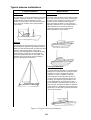
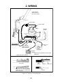
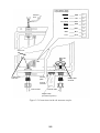
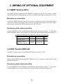
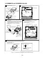
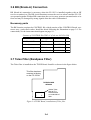
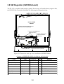
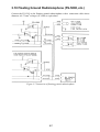
1
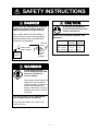
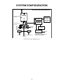
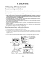
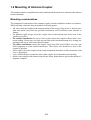
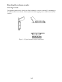
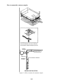
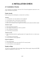
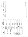
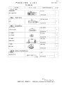
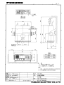
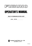
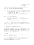
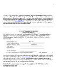
C
Yo u r L o c a l A g e n t/D e a le r
9-52, A shihara-cho,
N ishinom iya, Japan
Te l e p h o n e :
Te l e f a x :
0 7 9 8 -6 5 -2 111
0798-65-4200
A ll rig h ts re s e rv e d .
Printed in Japan
PU B. N o. IM E-56140-E
(T E N I)
FS-1503
FIRST
EDITIO N
E
:
:
APR.
JUL.
1998
4, 2001
SAFETY INSTRUCTIONS
DANGER
CAUTION
Never touch the SSB antenna, antenna
coupler or lead-in insulator when the
SSB radiotelephone is transmitting.
Ground the equipment to
prevent electrical shock and
mutual interference.
High voltage which will cause death or
serious injury is present at the locations
mentioned above when the SSB radiotelephone is transmitting.
Indoor
Antenna Wire
(High Voltage)
Antenna
Coupler
Observe the following compass safe
distances:
Antenna
Wire
Equipment
Standard
compass
Steering
compass
Transceiver
Ant. Coupler
MIC, Handset
1.1 m
0.6 m
0.6 m
0.8 m
0.5 m
0.4 m
Lead-in
Insulator
(High
Voltage)
WARNING
Do not open the cover
unless totally familiar with
electrical circuits and
service manual.
High voltage exists inside the
equipment, and a residual
charge remains in capacitors
several minutes after the
power is turned off. Improper
handling can result in electrical shock.
Turn off the power at the switchboard
before beginning the installation.
Fire or electrical shock can result if the
power is left on.
i
i
TABLE OF CONTENTS
EQUIPMENT LISTS ...................................................................................................... iii
SYSTEM CONFIGURATION ..................................................................................... v
1. MOUNTING
1.1 Mounting of Transceiver Unit .................................................................................... 1-1
1.2 Mounting of Antenna Coupler.................................................................................... 1-3
1.3 Ground System ...........................................................................................................1-6
1.4 Mounting of Antenna ................................................................................................. 1-7
2. WIRING ........................................................................................................................ 2-1
3. WIRING OF OPTIONAL EQUIPMENT
3.1 NBDP Terminal DP-6................................................................................................. 3-1
3.2 DSC Terminal DSC-60 ...............................................................................................3-1
3.3 Remote Station RB-500 ............................................................................................. 3-2
3.4 Distributor DB-120/DB-500 ...................................................................................... 3-2
3.5 REMOTE and CONTROL Boards ............................................................................. 3-3
3.6 BK (Break-in) Connection ......................................................................................... 3-4
3.7 Telex Filter ................................................................................................................. 3-4
3.8 SW Regulator (SW REG board) ................................................................................ 3-5
3.9 Dummy Load ............................................................................................................. 3-6
3.10 Floating Ground Radiotelephone (FS-5000, etc.) .................................................... 3-7
4. INSTALLATION CHECK
4.1 lnstallation Checks ..................................................................................................... 4-1
4.2 User Channel Registration ......................................................................................... 4-2
PACKING LISTS .......................................................................................................... A-1
OUTLINE DRAWINGS .............................................................................................. D-1
SCHEMATIC DIAGRAMS ....................................................................................... S-1
ii
EQUIPMENT LISTS
Standard Set
Name
Code No.
Qty
FS-1503
—
1
FS-1503A
—
Antenna Coupler
AT-1503
—
1
Accessories
FP05-05000
000-050-908
1
With MIC
FP05-05010
000-050-909
1
No MIC
Spare Parts
SP05-04400
005-939-850
1
For transceiver unit
Installation
Materials
CP05-07600
000-050-906
1
With antenna coupler
CP05-07610
000-050-907
1
No antenna coupler
Transceiver Unit
Type
Remarks
With power cable
For U.S.A
Note: See packing lists on pages A-1 to A-4 for details.
iii
Optional Equipment
Name
Type
Code No.
Qty
Remarks
AC-DC Power
PR-270
—
1
DC-DC Converter
PC-220
—
1
REMOTE-A Kit
OP05-82
005-939-810
1
For RS-232C
REMOTE-B Kit
OP05-83
005-939-820
1
For current loop
CONTROL Kit
OP05-41
005-920-330
1
BK connection
Bandpass Filter
SF0L04
000-116-693
1
For NBDP/DSC Terminal
SW REG Kit
OP05-84
005-939-830
1
Dummy Load Assy.
OP05-85
005-939-840
1
Whip Antenna
FAW-6D
000-572-128
1
Whip Antenna
FAW6R2
000-572-108
1
Whip Antenna
FAW-6RP2
000-572-109
1
Whip Antenna
FAW-6R2A
000-107-921
Whip Antenna
FAW-6RP2A
000-107-920
1
Doublet Antenna
E22
000-050-632
1
Single Wire
Antenna
E24
000-050-634
1
Double-span
Antenna
E25
000-050-635
1
Whip Antenna
Lead-in Kit
E26
000-050-636
1
Whip Antenna
Feeder
E27
000-050-637
1
Handset
HS-6000FZ5
000-112-623
1
Noise-cancelling
MIC
M112D
4509910
000-116-487
1
Distributor
DB-120
—
1
Distributor
DB-500-RS(E)
—
1
Remote Station
RB-500
—
1
Earth Plate
04S40801
000-572-187
1
30x1200x0.3 mm
Coaxial Cable
05S0949
000-130-485(6,7,8)
1
20, 30, 40, 50 m
Control Cable
05S0462
000-113-361(2,3,4)
1
20, 30, 40, 50 m
External
Loudspeaker
SEM-21Q
000-144-917
1
iv
SYSTEM CONFIGURATION
FS-1503 SYSTEM CONFIGURATION
Antenna Coupler
AT-1503
Distributor
DB-500
OR
Transceiver Unit
FS-1503
SSB TRANSCEIVER FS-1503
SIMP
R
AGC
STATION
MODE
1
CURS
2
CLARI
3
4
SQL
5
SCAN
6
TUNE
7
H/L
8
9
2182
INT
0
DSC Terminal
DSC-5/6
NBDP Terminal
DP-5/6
Remote Station
RB-500
Distributor
DB-120
*
TX
RX
0 2 4 6 8 10 S
AGC NB
H3E
CH
START
MIC
(Handset
optionally
available)
MIC
VOLUME
RF GAIN
ALM
ENT
TEST
PC-220 13.6 V
24 VDC
FREQ/CH
OFF
13.6 V
External
Speaker
DSC Terminal
DSC-60
NBDP Terminal
DP-6
PR-270
100/110/200/220 VAC
* Optional pcb (REMOTE A or
REMOTE B) required.
13.6 VDC
FS-1503 system configuration
v
Option
1. MOUNTING
1.1 Mounting of Transceiver Unit
General mounting considerations
The transceiver unit can be mounted on the overhead, a bulkhead, on a tabletop, or in a console
(flush mounting).
When selecting a mounting location keep the following points in mind:
• Make sure the location is strong enough to support the unit under the conditions of continued
vibration and shock normally encountered on the boat. Where necessary, reinforce the mounting location by lining block or doubling plate.
• Locate the unit where it is easily accessible and does not interfere with personnel or operation of other equipment; for example, ship’s wheel.
• Leave enough space around the sides and rear of the unit so a service technician can access
the connectors for maintenance.
• Observe the compass safe distance listed in the Safety Instructions to prevent deviation of a
magnetic compass.
• If the equipment is to be installed without the hanger, leave sufficient space underneath the
the equipment to allow for circulation of cooling air.
Mounting on overhead, bulkhead or tabletop
1. Using the hanger as a template, mark hole locations.
2. Fix the hanger with four sets of self-tapping screws and washers (supplied). (If extra support
is required, drill six pilot holes and use bolts, nuts and flat and slotted washers instead of the
tapping screws.)
3. Screw washers and knobs into the unit. Set the unit to the hanger and tighten the knobs.
M5 bolt
Slotted washer
306
For added support,
use nuts, bolts and
washers instead of
tapping screws.
Flat washer
112
265
Tapping
screw
Flat
washer
Flat washer
M5 nut
Knob
115
Washer
100
150
100
150
90
190
126
155
303
Figure 1-1 How to install the transceiver unit in the hanger
1-1
Console mounting
Mounting considerations
In addition to the general mounting considerations mentioned on the previous page, keep the
following points in mind when selecting a mounting location:
• Select a place where the LCD can be easily viewed, keeping in mind the LCD viewing angle
is as shown in Figure 1-2.
• Leave sufficient space around the unit to permit dispersal of heat after a long transmission.
How to mount the transceiver unit in a console
This method does not require any additional kit. However, the dimensions of the cutout must be
accurate since the hanger also is installed. Prepare a cutout in the mounting location whose
dimensions are as shown in Figure 1-2.
LCD Viewing 40°
Angle
99
10°
112
37.5
103
90
Figure 1-2 Mounting dimensions for console mounting
1-2
1.2 Mounting of Antenna Coupler
The antenna coupler is installed between the antenna and the transceiver, and tunes the antenna
to the transmitter.
Mounting considerations
The splashproof construction of the antenna coupler permits installation indoors or outdoors.
When selecting a location, keep in mind the following points:
• All wires from the coupler to the antenna radiate radio energy. Keep wires as short as possible and routed away from any grounded conductors such as lifelines, mast shrouds, or
fittings.
• For optimum radio energy, locate the coupler close to the antenna base and as near to the
ground as possible.
• For outdoor installation, be sure to select a place where the coupler will not take a continual soaking. If necessary, cover the top and sides with a wooden housing or by sealing any
opening in the top or sides with silicone sealant.
• For indoor installation, locate the coupler away from GPS and SATNAV receivers and
radio equipment to avoid mutual interference. The lead-in wire should be as near to the
coupler as possible.
• Select a place where the coupler can be easily maintained, but where it will not interfere with
crew or passengers.
• Leave sufficient space around the sides of the coupler for maintenance and checking.
• Observe the compass safe distance listed in the Safety Instructions to prevent deviation of a
magnetic compass.
1-3
Mounting the antenna coupler
Mounting methods
The antenna coupler can be fixed to the floor, bulkhead, or on the overhead. For mounting on
the bulkhead, floor or overhead, fix the coupler with either tapping screws or M6 nuts, bolts and
washers.
INDOOR USE ONLY
Figure 1-3 Typical antenna coupler installations
1-4
How to mount the antenna coupler
For thin bulkhead, use nuts, bolts and
and washers instead of tapping screws.
Lead-in
insulator
ANTENNA SELECTOR
Wire clip
Stand-off
insulator
From antenna selector
INDOOR INSTALLATION
Figure 1-4 How to mount the antenna coupler
1-5
1.3 Ground System
A good antenna can work well only when it is connected to an efficient rf ground. Without a
good ground system, the full potential of this radio cannot be realized.
CAUTION
Ground the equipment to
prevent electrical shock
and mutual interference.
Ground for metallic hull
Run a copper strap (option or local supply) between the earth terminal on the antenna coupler
and the ship’s superstructure. The length of the copper strap should be as short as possible. (If
the coupler is mounted on a metallic mast you can ground the copper strap to the mast; weld a
stainless steel bolt to the mast and connect the copper strap there.)
Copper strap
Braze
Ground plate
(piece of steel plate)
Solder
Weld to ship's superstructure.
For outdoor installation,
paint to prevent rust.
Figure 1-5 Ground for a metallic hull
Ground for non-metallic hull
Run a copper strap (option or local supply) between the ground terminal of the antenna coupler
and the radio ground system. The length of the copper strap should be as short as possible.
Grounding the transceiver unit
Run the ground wire (supplied) between the transceiver unit and ship’s ground, to prevent
interference and protect the equipment against lightning.
1-6
1.4 Mounting of Antenna
About antennas
The antenna plays the most important role in radio communication. If it cannot receive or
transmit effectively because of improper installation, even the most sophisticated transceiver
will be rendered useless.
There are various types of SSB antennas. The most commonly used are a long wire and a whip.
Whatever antenna is to be used, the antenna coupler can tune a long wire or whip whose total
length is 6 to 15 meters. Although a longer antenna is preferable when the radio is operated only
on low frequencies, use this size of antenna to ensure stable automatic tuning on all bands.
A long wire antenna is inexpensive and in general provides better performance than a whip
antenna, provided the vertical part is long enough.
A whip antenna is easier than a long wire antenna to install and provides good overall coverage
of most SSB frequencies. In fact, if you don’t plan to venture more than 500 miles from shore
and the ground system is excellent, a simple 7 m (23 feet) whip antenna will probably suffice.
A whip is installed as high as possible (though height is not so critical as with VHF since SSB
is frequency dependent, not range dependent), away from any nearby objects.
Mounting considerations
When selecting a mounting location, keep the following points in mind:
• The length of the vertical portion should be longer than 4 meters, and the slant angle of that
part should be within 10 degrees of vertical.
• Separate the antenna as far away as possible from stays, metallic objects, direction finder
antenna, Inmarsat antenna.
• Locate the insulator away from funnels and masts.
• If the antenna coupler is installed outdoors, use a lead-in insulator to make the connection. If
necessary, use a high quality antenna switch and stand-off insulator.
• If the antenna is connected directly to the coupler, use a strain insulator to prevent insulator
fatigue.
1-7
Typical antenna installations
Long wire antenna
Whip antenna
Ship station
Power boats
On ship stations, the long wire antenna is spanned
between supporting structures. The length of the
horizontal wire should be between 6 and 15
meters. And the length of the vertical wire should
be no less than 5 meters, the longer the better
transmission.
On power boats, selection of a mounting location
for a whip antenna is much easier, since there is
no mast or deck fixture to worry about. A whip
antenna can be installed almost anywhere,
again the higher the better. If your boat has a
flybridge, install it there. If not, install it atop the
cabin. Make sure the mounting location is
sufficiently apart from any nearby objects
which might affect communication.
Sailboat
On sailboats, the long wire antenna is mounted on
the backstay using special high-voltage insulators.
Make sure the selected location is sufficiently apart
from any metal riggings which might cause
detuning. If a wire topping lift is used with an insulated backstay, special care must be taken to
ensure the topping lift does not get caught in the
backstay since the antenna may be shorted to
ground—damaging the transmitter.
Fishing boat/Sailboat
For whip antenna installation on a fishing boat or
sailboat, the mounting location must be chosen
carefully so as not to interfere with vessel
operation. In case of a sailboat, locate the
antenna away from the spinnaker, jib and of
course the boom. Stay especially clear of the
backstay. The taffrail is a good location in the
event of dismasting, since the antenna won’t
be carried away. The best location, however, is
atop the mast, the higher the better for effective
communication. It is always a good idea to keep
spare wire or an emergency antenna onboard in
case of an emergency.
Figure 1-6 Typical antenna installations
1-8
2. WIRING
Total length of
antenna should
be 6 to 15 meters.
Fuse Holders
Power Cable
(RED)
_
(BLK)
12VDC
Min
120AH
+
* *
Not used
Handset
(option)
Antenna
Coax.
Cable
Control Cable
Ground
wire
DSC Terminal
NBDP Terminal
Remote Station
* Cable fabrication required.
CONTROL CABLE 05S0949-0
Speaker
(option)
Dimensions in millimeters unless noted
otherwise.
05S0462-1 COAX. CABLE
5
90
10
Drain Wire
Sheath
Cover drain wire with vinyl tubing.
Fasten with screw on shield case.
(See next page.)
Shield
Insulator
Figure 2-1 General wiring diagram
2-1
25
Inner Core
Leave slack in wires
to prevent breakage.
Antenna
wire
DUMMY
GRN
7
THRU
YEL
6
NC (IANT)
ORG
5
BUSY
RED
4
TUNE
BRN
3
GND
BLK
2
+12 V
WHT
1
Shield case
TB1
7 6 5 4 3 2 1
Fasten drain
wire here.
TB2
Ground
plate
Clamp cable
at shield.
Ground
terminal
Control cable
Coaxial cable
Copper strap
(Connect to ground.)
Figure 2-2 Connections inside the antenna coupler
2-2
3. WIRING OF OPTIONAL EQUIPMENT
3.1 NBDP Terminal DP-6
The NBDP Terminal connects to the REMOTE connector on the FS-1503. It has a remote
control function which automatically sets class of emission and frequency data at the FS-1503.
Remarks on connection
Connect the NBDP Terminal to the FS-1503 with a 13-pair twisted cable. For the cable with no
connectors, attach connector types SRCN (at FS-1503) and D-sub (at DP-6). For cable with Dsub connector, connect the SRCN connector at the FS-1503 side.
Necessary parts, interconnection
Requires REMOTE-A Kit. Install the board following the illustration on page 3-3. Note that a
narrow bandpass filter is also available. For connection, interconnection diagram on page S-1.
Contents of REMOTE-A Kit OP05-82 (Code no. 005-939-810)
Name
Type
Code No.
Qty
REMOTE PCB
05P0457
005-840-980
1
Connector Assy.
(REMOTE connector)
05S0928
000-130-440
1
3.2 DSC Terminal DSC-60
The DSC Terminal connects to the REMOTE connector on the FS-1503.
Remarks on connection
When both the NBDP Terminal and DSC Terminal are to be connected, connect them via the
Distributor DB-500.
Necessary parts, interconnection
Requires REMOTE-A Kit. Install the board following the illustration on page 3-3. Note that a
narrow bandpass filter is also available. See the interconnection diagram on page S-1.
3-1
3.3 Remote Station RB-500
Connect to the REMOTE connector on the FS-1503. If more than two RB-500s or DSC, NBDP
are to be installed, connect them via the Distributor DB-500.
Necessary parts
Requires REMOTE-B Kit (current loop) for connection of a single remote station or REMOTEA Kit when the DB-500 is connected. Install the board following the illustration on page 3-3.
Contents of REMOTE-B Kit OP05-83 (Code no. 005-939-820)
Name
Type
Code No.
Qty
REMOTE PCB
05P0458
005-840-990
1
Connector Assy.
(REMOTE connector)
05S0928
000-130-440
1
3.4 Distributor DB-120/DB-500
A distributor enables connection of multiple external equipment. The DB-120 connects one
NBDP Terminal and one DSC Terminal, and the DB-500 connects up to four external equipment: one NBDP terminal, one DSC terminal, and two remote stations. In either case the REMOTE-A board is also required.
NBDP TERMINAL
SSB
DISTRIBUTOR
DB-500
DSC TERMINAL
REMOTE STATION
REMOTE STATION
Figure 3-2 Function of the Distributor DB-500
3-2
3.5 REMOTE and CONTROL Boards
1 1.Remove cover and shield cover.
2 1. Unplug all connectors from TX/RX Board; dismount the board.
COVER
BOTTOM VIEW
J4
PAN HEAD SCREW
M3X6 (9 PCS.)
J1
U27
SHIELD
COVER
U26
BINDING SCREW
M4X10 (6 PCS.)
J2
TX/RX BOARD
05P0666
J8
GASKET
J11
J10 J6
MAIN BODY
J7
J9
HANGER GASKET
3
1. Solder CONTROL Board and/or REMOTE Board to
TX/RX Board.
2. Coat left rear corner and right front corner of CONTROL
and REMOTE Boards with silicone sealant (type KE348TRTV, FURUNO code no. 000-801-041).
3. Fasten CONTROL connector and/or REMOTE
connector.
4
3 1. Mount TX/RX Board.
2. Plug in REMOTE connector and/or CONTROL
connector to TX/RX Board.
3. Attach connectors to the TX/RX Board.
4. Attach shield cover.
REMOTE CONNECTOR (16P)
CONTROL CONNECTOR (7P)
CONTROL BOARD
05P0549
REMOTE-A BOARD 05P0457
or
REMOTE-B BOARD 05P0458
BOTTOM
VIEW
CONTROL
CONNECTOR
ASSY.
J5
J4
J3
J1
TOP
VIEW
U2
U27
6
U2
TX/RX BOARD
7
GASKET (3)
FLAT WASHER
NUT
J2 TX/RX BOARD
GASKET
J8
05P0666
PAN HEAD SCREW
M3X10 (2 PCS.)
REMOTE
CONNECTOR
ASSY.*
PLUG
PAN HEAD SCREW
J10 J6
* Male and female connector
attached.
5
U26
PAN HEAD SCREW
M3X10
J9
PAN HEAD SCREW
M3X8 (5 PCS.)
1. Attach vinyl tape (approx. 50 mm) to each outside corner of cover.
2. Insert gasket, and then fix it with vinyl tape at corners of cover.
3. Insert main body to cover.
4. Remove vinyl tape.
5. Fasten cover to main body with binding screws.
COVER
Vinyl tape
Cover
Groove is outside.
ATTACH VINYL
TAPE
Gasket
GASKET
Figure 3-3 Installation of REMOTE and CONTROL boards
3-3
J7
J11
3.6 BK (Break-in) Connection
BK (Break-in) connection is necessary when the FS-1503 is installed together with an HF
receiver or transceiver. The BK circuit functions to mute the receiver when it and the FS-1503
are operated together. With no BK connection, the receiver may generate unwanted noise or its
front end may be damaged by strong signals when the radio is transmitted.
Necessary parts
The BK function requires the CONTROL Kit, which consists of the CONTROL Board, connector assy., gasket and washer. Install the board following the illustration on page 3-6. For
connections, see the interconnection diagram on page S-1.
Contents of CONTROL Kit OP05-41 (Code no. 005-920-330)
Name
Type
Code No.
Qty
CONTROL PCB
05P0459
005-841-000
1
Gasket (3)
05-029-0122-3
100-087-843
1
Connector Assy.
05S0846
000-125-319
1
Washer
16.2x22.0x0.5
000-801-849
1
3.7 Telex Filter (Bandpass Filter)
The Telex filter is installed on the TX/RX Board. Install it as shown in the figure below.
This filter has been
mounted at factory
on the FS-1503A.
TX/RX BOARD
05P0666
OUT
E
FL3
Solder Telex
filter to FL3.
Note direction
on underside of
filter.
IN
E
Figure 3-4 TX/RX Board, installation of Telex filter
3-4
3.8 SW Regulator (SW REG board)
The FS-1503 is supplied with negative ground. If necessary, to float the battery negative line,
the SW REG Kit is available. Install the kit following the illustration below.
J5
J6
PA/FIL BOARD
05P0667
2 Fasten SW. REG Board with five
pan head screws-B (M3X8).
4 Connect CONNECTOR
ASSY. (2 PCS.)
5 Fasten shield cover
with four screws
J7
(M3 x 6).
J3
SW. REG BOARD
05P0668
J1
J2
3 Fasten FETs with
screw-A (M3 x 8).
J2
1 Place heat sheet on pedestal.
Figure 3-5 Transceiver unit, top view, installation of SW REG Board
Contents of SW REG Kit OP05-84 (Code no. 005-939-830)
Name
Type
Code No.
Qty
Remarks
SW REG
05P0668
005-940-830
1
Connector Assy.
PH040-100
000-130-434
2
Heat Sheet
BFG-20
000-539-110
2
Screw
M3 x 6
000-881-103
4
For shield cover
Screw-A
M3 x 8
000-881-104
2
For FET
Screw-B
M3 x 8
000-881-404
5
For SW REG pcb
Shield Cover
05-077-1141
100-253-840
1
3-5
3.9 Dummy Load
The dummy load enables testing of the two-tone alarm. Install the board following the figure
below. CHANGE SYSTEM SETTING 9917 to 1.
W4 should not touch
TB4 or W3.
TB4
ANT
Fasten wire with cable tie.
Gap between inner wall
and wire should be more
than 15 mm.
W4 WIRE ASSY.
Separare these wires: Bend crimp-on
lug attached to TB1 upward; bend
crimp-on lug attached to TB3 downward.
W3 WIRE ASSY.
NOTICE
W6
WIRE ASSY.
Separate wire assemblies
W3 and W4 more than
15 mm from each other.
TB2
TB1
TX
TX
OUT IN
TB3
DUMMY
J1
J
DUMMY CONT
BOARD 05P0670
E
NOTICE
J2
Do not route
wires within
this area.
TB4
Fasten dummy load
assy. to shield case
with four existing
screws (4 pcs.).
E
DUMMY LOAD ASSY.
W5
WIRE ASSY.
Figure 3-6 COUPLER board, installation of dummy load
3-6
TB3
3.10 Floating Ground Radiotelephone (FS-5000, etc.)
Connect the FS-1503 to the floating ground radiotelephone with a connection cable whose
diameter is 0.75 mm2 or larger (3C cable or equivalent).
FS-1503
Figure 3-7 Connection of floating ground radiotelephone
3-7
4. INSTALLATION CHECK
4.1 lnstallation Checks
After completing the installation, check the FS-1503 and all equipment connected to it for
proper connection and operation.
Visual checks
Before turning on the radiotelephone, visually check it as follows:
Antenna
1)
2)
3)
4)
Are fixing bolts, wire clips, shackles securely tightened?
Are the antenna and/or coaxial lead-in waterproofed?
Is the antenna wire securely connected to the coupler?
Make sure no mechanical stress is applied to the antenna at the connection with the coupler.
Antenna coupler
1)
2)
3)
4)
Is the unit perfectly grounded?
Is the length of the ground wire as short as possible?
Is the ventilation seal attached?
Are all wirings correctly made?
Transceiver unit
1) Is the unit grounded with the supplied ground wire? Length of the wire is as short as possible?
2) Are all wirings correctly made?
3) Are all connectors securely tightened?
Optional equipment
1) Is the unit grounded?
2) Are all wirings between the unit and the FS-1503 correctly made?
3) Are all connectors securely tightened?
Supply voltage
The transceiver unit should be off to check supply voltage. Measure supply voltage at the POWER
connector. It should be 13.6 VDC ±15%.
4-1
Performance
If no problems were found in the preceding sections, then turn on the transceiver and check it
for proper performance.
Receiver
1. Turn on the loudspeaker.
2. Turn off the squelch.
3. Check that all the bands can be received clearly.
If signal strength is too low or there is too much noise return to “Visual check” and recheck.
Double check the antenna and ground. If there is no trouble, proceed to the next step.
Transmitter
On each band, confirm that the antenna is automatically tuned when the [TUNE/7] key or the
PTT switch is pressed. (“OK” appears when tuning is successfully completed.)
Automatic tuning of the antenna should take no longer than 15 seconds. If you find a channel
which takes more than 15 seconds to tune, recheck antenna length and ground.
Noise
Noise generated on board or by electrical storms can severely degrade communication. Stormgenerated static, unfortunately, is impossible to suppress or eliminate. Radio traffic on lower
frequency bands is sometimes completely blocked out in certain areas.
Man-made noise, however, can often be suppressed by a marine electronics technician, using
special noise filtering and shielding techniques. In most cases the source of electrical noise is
the ignition system, although generators, alternators, winches, pumps, radar and echo sounder
can interfere with radio communication as well.
Turn on electrical equipment one by one to check for interference to the FS-1503.
Because no two boats are built or equipped exactly alike, there is no one general noise suppressing technique that can be applied to all cases. If electrical noise interferes with SSB operation,
consult a marine electronics technician.
4.2 User Channel Registration
Register permitted frequencies, referring to the operator’s manual.
4-2