1
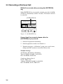
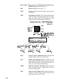
VHF RADIOTELEPHONE
MODEL
FM-8700
C
Your Local Agent/Dealer
9-52, Ashihara -cho,
Nishinomiya, Japan
Telephone:
Telefax:
0 7 9 8 - 6 5 - 2111
0798-65-4200
All rights reserved.
(Y O S H)
Printed in Japan
P U B . N o . O M E -5 6 1 7 0
FM -8 7 0 0
FIRST
EDITION
K1
:
:
A P R. 199 8
JUL . 3 , 2 0 0 2
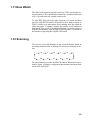
CANCELING DISTRESS ALERT
If less than five seconds has elapsed since the [DISTRESS] key was pressed, the distress alert
may be canceled by pressing the [ALARM STOP] key. Otherwise, do the following:
1. Switch off equipment immediately.
2. Switch equipment on and set to Channel 16.
3. Transmit message to "All Stations” giving your vessel's name, callsign and DSC number to
cancel the distress alert.
Example message:
All Stations, All Stations, All Stations
This is VESSEL'S NAME, CALLSIGN,
DSC NUMBER, POSITION.
Cancel my distress alert of
DATE, TIME, UTC.
=Master, VESSEL'S NAME, CALLSIGN.
DSC NUMBER, DATE, TIME UTC.
i
i
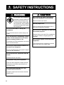
SAFETY INSTRUCTIONS
WARNING
Do not open the equipment.
Hazardous voltage which can
cause electrical shock, burn
or serious injury exists inside
the equipment. Only qualified
personnel should work inside
the equipment.
Do not disassemble or modify the
equipment.
Fire, electrical shock or serious injury can
result.
Turn off the power immediately if water
leaks into the equipment or the equipment is emitting smoke or fire.
Continued use of the equipment can cause
fire or electrical shock.
Do not place liquid-filled containers on
the top of the equipment.
Fire or electrical shock can result if a liquid
spills into the equipment.
Do not operate the equipment with wet
hands.
Electrical shock can result.
Keep heater away from equipment.
Heat can alter equipment shape and melt
the power cord, which can cause fire or
electrical shock.
Any repair work must be done by a
licensed radio technician.
Improper repair work can cause electrical
shock or fire.
ii
CAUTION
Do not touch any part of the antenna
when the equipment is transmitting.
Electrical shock can result.
Use the proper fuse.
Use of a wrong fuse can result in fire or
permanent equipment damage.
Do not use the equipment for other than
its intended purpose.
Personal injury can result if the equipment
is used as a chair or stepping stool, for
example.
Do not place objects on the top of the
equipment.
The equipment can overheat or personal
injury can result if the object falls.
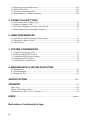
TABLE OF CONTENTS
FOREWORD ..................................................................................................................... v
SYSTEM CONFIGURATION .................................................................................. vii
1. VHF RADIOTELEPHONE OPERATIONAL OVERVIEW
1.1 Front Panel .................................................................................................................1-1
1.2 VHF Controls, Indications .........................................................................................1-2
1.3 Turning the Power On/Off..........................................................................................1-2
1.4 Selecting Channel Modes, Channels ..........................................................................1-3
1.5 Adjusting Volume of Loudspeaker .............................................................................1-3
1.6 Adjusting Squelch, Selecting Operating Functions ....................................................1-3
1.7 Transmitting ...............................................................................................................1-4
1.8 Selecting Output Power ..............................................................................................1-4
1.9 Turning the Loudspeaker On/Off ...............................................................................1-4
1.10 Automatic Selection of CH16 ..................................................................................1-4
1.11 Dual Watch ...............................................................................................................1-5
1.12 Scanning ...................................................................................................................1-5
1.13 Remarks on Voice Communications ........................................................................1-6
2. DSC TERMINAL OPERATIONAL OVERVIEW
2.1 DSC Controls, LED Warnings ...................................................................................2-1
2.2 DSC Operational Overview .......................................................................................2-4
2.3 Turning Remote & Auto Acknowledge On/Off .........................................................2-7
3. DSC DISTRESS COMMUNICATIONS
3.1 Distress Alert Transmission ........................................................................................3-1
3.2 Manual Entry of Own Ship’s Position and Time........................................................3-3
3.3 Canceling a Distress Call ...........................................................................................3-4
3.4 Receiving Distress Alert from Other Vessel, Transmitting DIST ACK Signal ..........3-5
3.5 Distress Alert Relay ....................................................................................................3-9
4. DSC OPERATION FOR NON-DISTRESS CASES
4.1 Transmitting Individual Calls .....................................................................................4-1
4.2 Receiving Individual Calls (ACK RQ) ......................................................................4-5
4.3 Transmitting All Ships Calls ......................................................................................4-9
4.4 Receiving All Ships Calls .........................................................................................4-12
iii
4.5 Preparing and Saving Messages ...............................................................................4-16
4.6 Writing Over Files ....................................................................................................4-18
4.7 Opening, Transmitting Files .....................................................................................4-19
4.8 Transmit/Receive Message Memory ........................................................................4-20
5. OTHER CALLING TYPES
5.1 Selection of Other Calling Types ...............................................................................5-1
5.2 Making Telephone Calls .............................................................................................5-3
5.3 Receiving Telephone Call from Coast Station ...........................................................5-6
5.4 Other Station IDs and Telephone Numbers ................................................................5-7
6. USER PREFERENCES
6.1 Automatic or Manual Printing (Printer setup) ............................................................6-1
6.2 Turning Key Beep On/Off ..........................................................................................6-4
6.3 Alarm Setup ................................................................................................................6-5
7. SYSTEM CONFIRMATION
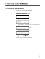
7.1 Confirming Own Ship’s ID ........................................................................................7-1
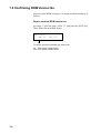
7.2 Confirming ROM Version No. ...................................................................................7-2
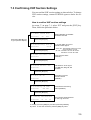
7.3 Confirming VHF Section Settings .............................................................................7-3
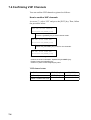
7.4 Confirming VHF Channels ........................................................................................7-4
7.5 Confirming Tx Output Power ....................................................................................7-5
8. MAINTENANCE & TROUBLESHOOTING
8.1 Maintenance ...............................................................................................................8-1
8.2 Troubleshooting..........................................................................................................8-1
8.3 Diagnostic Test ...........................................................................................................8-2
SPECIFICATIONS ..................................................................................................... SP-1
APPENDIX ...................................................................................................................... A-1
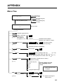
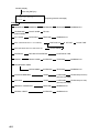
Menu Tree ....................................................................................................................... A-1
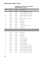
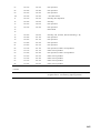
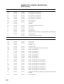
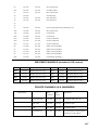
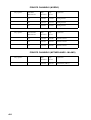
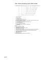
Marine VHF Channel Lists ............................................................................................. A-4
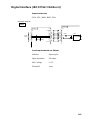
Digital Interface (IEC 61162-1 Edition 2)....................................................................... A-9
INDEX ......................................................................................................................... Index-1
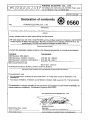
Declaration of conformity to type
iv
FOREWORD
A Word to FM-8700 Owners
Congratulations on your choice of the FURUNO FM-8700 VHF
Radiotelephone. We are confident you will see why the FURUNO
name has become synonymous with quality and reliability.
For over 40 years FURUNO Electric Company has enjoyed an
enviable reputation for quality marine electronics equipment. This
dedication to excellence is furthered by our extensive global network of agents and dealers.
This equipment is designed and constructed to meet the rigorous
demands of the marine environment. However, no machine can
perform its intended function unless operated and maintained properly. Please carefully read and follow the recommended procedures
for operation and maintenance.
We would appreciate hearing from you, the end-user, about whether
we are achieving our purposes.
Thank you for considering and purchasing FURUNO equipment.
v
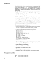
Features
The FURUNO FM-8700 is a cost-effective all-in-one marine VHF
radio system consisting of a 25 W VHF radiotelephone, a DSC
modem, a CH 70 watch receiver, and a duplexer unit. It complies
with GMDSS carriage requirements for safety and general communications.
The FM-8700 offers simplex/ full-duplex voice communications
on ITU channels in the marine mobile VHF band. The features
include Dual Watch which allows a continuous watch on CH16
and another selected frequency.
Full Class-A DSC functions are provided for distress alert transmission and reception, as well as the general call formats (Individual telephone, All Ships, Group and Area Call). Distress alert
can be readily transmitted but an arrangement is provided to prevent accidental activation. The FM-8700 maintains a continuous
watch on CH70 even while another VHF channel is in use. Aural
and visual alarms are given to incoming DSC messages.
The main features of the FM-8700 are
• Compact cabinet allows for flexible and space-saving installation on a navigation console or at the conning position
• Conforms to the following standards and regulations:
IMO A. 694(17)
IMO A. 803(19)
IMO A. 524(13)
IMO MSC 68(68), MSC/Circ.862
IEC-61097-3/7/8
IEC-60945 (3rd edition)
IEC-61162-1
ETS 300 338, 301 033, 300 162
ITU-R M.493-9, M.541-8, M.689-2
• Full-duplex communications
• Precision PLL frequency synthesizer for high frequency stability as required for DSC operation
• Dual Watch and Multiple Watch
• Continuous DSC watch on CH70
• Prevention of accidental distress alert
• File editing for emergency readiness
• Automatic entry of own ship position with manual override
Program number
DSC
RT
vi
0550192004 (version 1.06)
0550193004 (version 1.04)
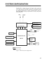
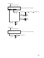
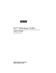
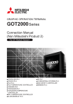
SYSTEM CONFIGURATION
The FM-8700 is a highly advanced, full-duplex, fully synthesized
25 W VHF transceiver with DSC terminal. It is designed to satisfy
the stringent requirements of marine communications, and complies with GMDSS carriage requirements for safety and general
communications.
VHF
Antenna
CH70 RX
Antenna
Navigation Device
DX-8700
Wing Handset (port)
DUPLEXER UNIT
Wing Handset (starboard)
AC/DC
Power
Supply
Unit PR-300
110/220 VAC
24 VDC
Handset
24 VDC
TRANSCEIVER UNIT
External Speaker
FM-8700
Distress
Message
Controller
DMC-5
Remote Station RB-700
Printer
Interface
IF-8500
Distributor DB-500
Printer
PP-510
: Standard Supply
: Optional Supply
Figure 1 FM-8700 system configuration
vii
This page is intentionally left blank.
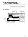
1. VHF RADIOTELEPHONE
OPERATIONAL OVERVIEW
The FM-8700 system consists of a transceiver unit, a duplexer unit
and two antennas. The transceiver unit contains a VHF transmitter, receiver, and channel 70 watch receiver module. All operations are controlled on its front panel.
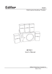
1.1 Front Panel
Controls for
DSC calling
Keyboard
(for DSC operation)
LCD
VHF RADIOTELEPHONE FM-8700
POSITION AUTO ACK
Watch CH 70
auto
1
PRINT
DISTRESS CANCEL
DISTRESS
VOLUME
(PUSH)
Controls for
VHF operation
OFF
SQUELCH
OFF/DW/SCAN(PUSH)
ALARM
STOP
LOW
TX
HI
LOW
CH16
CALL
CHANNEL
REM USA WX PRIV MODE(PUSH)
2
TEST
3
CANCEL
CONTRAST VOLUME
4
5
6
FILE
RCVD
XMTD
7
8
9
0
SELECT
ENT
AUTO
CH16 key
Channel selector
Volume with
High/Low
power
(Press for Mode selection.)
Power ON/OFF
(Press to turn
Squelch control
Channel No. display
loudspeaker on/off.) (Press for DW, Scan.)
Figure 1-1 FM-8700 transceiver unit
1-1
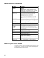
1.2 VHF Controls, Indications
Control
Function
CHANNEL/
MODE
CHANNEL (Rotary control): Selects a
channel.
MODE (Push): Changes modes in order of
INTL, USA, WX and PRIV. (USA, WX and
PRIV modes available where permitted.)
SQUELCH/
DW/SCAN
SQUELCH (Rotary control): Mutes the
receiver when no signal is present on the
channel selected. AUTO position
automatically reduces white noise.
DW/SCAN (Push): Changes the operating
function in order of Dual Watch, Scan and
Off.
Rotation turns the power on/off and adjusts
the volume of the loudspeaker. Pressing turns
off the internal loudspeaker.
VOLUME
HI/LOW key
Alternates high and low output power.
CH16 key
Selects channel 16.
Indication
Meaning
Internal loudspeaker OFF by pressing the
VOLUME control. Internal loudspeaker is
automatically turned off whenever the handset
is set in its rest.
LOW
Lights RF power is LOW.
TX
REM
Lights while transmitting.
Lights when FM-8700 is being controlled by
Remote Station RB-700.
USA
USA mode. (Some ITU duplex channels are
used as simplex channels.)
WX
Lights when a weather channel is selected.
(Available in USA version.)
DW for Dual Watch; SCAN for scanning.
DW/SCAN
1.3 Turning the Power On/Off
To turn the power on, turn the VOLUME control clockwise until
you hear a click. To turn the power off, turn the control fully counterclockwise until you hear the click.
1-2
1.4 Selecting Channel Modes, Channels
Selecting channel modes
While pressing the CHANNEL selector, press the CH16 key to
select the channel mode: International, USA (in the case of USA
channel permitted), private (if authorized), or weather mode (USA
channel permitted). The International version of the FM-8700 has
no such selection.
On the weather channel mode, a beep is emitted when the weather
alert tone is received.
Note: Private channels are available only where permitted by the
authorities.
Selecting channels
Rotate the CHANNEL selector clockwise (counterclockwise) to
display desired channel in the channel No. display window.
1.5 Adjusting Volume of Loudspeaker
The VOLUME control adjusts the volume of the loudspeaker.
1.6 Adjusting Squelch, Selecting Operating Functions
Adjusting squelch
The SQUELCH control adjusts the squelch threshold level. Adjust
it so that white noise heard in the loudspeaker just fades out. Perform this operation when no traffic is being received. AUTO squelch
automatically reduces white noise. Usually select the AUTO position. Avoid turning the squelch too far clockwise – you may miss a
long distance communication.
Note: To obtain correct scan watch/dual watch response, adjust
the SQUELCH control precisely.
Selecting operating function
Every pressing of the SQUELCH control changes the operating
function as follows:
OFF
DW
SCAN
1-3
1.7 Transmitting
Press the PTT (Press-to-talk) switch on the handset or microphone
to talk, and release it to listen for the response. The VHF section
keyboard accepts no key input when the PTT switch is operated.
Remarks on transmitting
• Before transmitting, think about the subjects which have to be
communicated and, if necessary, prepare written notes to avoid
unnecessary interruptions and ensure that no valuable time is
wasted on a busy channel.
• Listen before commencing to transmit to make certain that the
channel is not already in use.
1.8 Selecting Output Power
Each press of the [HI/LOW] key selects HI or LOW output power.
LOW appears when low power is selected. The transmitter power
is automatically set for low on the following channels:
International: CH15, CH17
USA:
CH13, CH15, CH17, CH67; to operate USA channel 13 or 67 in high power, keep [HI/LOW] pressed
while talking into the handset.
1.9 Turning the Loudspeaker On/Off
To turn the loudspeaker on/off, press the VOLUME control. The
loudspeaker off mark appears when the speaker is off. The loudspeaker is automatically turned off when the telephone handset is
used on semi-duplex channels.
1.10 Automatic Selection of CH16
Press the [CH16] key to select CH16, the International Calling and
Safety Channel. The use is limited to distress, safety and calling.
The transmission on CH16 (156.800 MHz) should be limited to
within 1 minute except for distress calling.
Avoid calling on CH16 for purposes other than distress, urgency
and very brief safety communications when another calling channel is available.
1-4
1.11 Dual Watch
The dual watch function permits watch on CH16 and another selected channel. CH16 and another channel are watched at intervals
of 0.15 seconds and one second, respectively.
To start DW, first select the other frequency to watch and then
press the SQUELCH control. When the receiver finds a signal on
CH16, it locks on it and restarts dual watching after the signal on
CH16 has gone. If another channel has traffic, it still continues
dual watch. The speech is heard intermittently. If you are annoyed
with the intermittence, turn off DW by pressing the PTT switch on
the handset or pressing the SQUELCH control.
1.12 Scanning
The receiver scans all channels in the selected channel mode in
ascending channel order, watching CH16 between channels as below:
1
16
2
16
3
16
4…
16
88
16
87
16
86
16…
To start scanning, press the SQUELCH control. When the receiver
finds a signal, scanning is stopped on that channel and starts dual
watch on it and CH16.
1-5
1.13 Remarks on Voice Communications
Automatic acknowledge (DSC operation) is automatically changed
to manual acknowledge when voice communications begin. (The
“auto” indication, however, remains on the screen.) This is done to
prevent break in communications. Automatic acknowledge is automatically restored once voice communications are terminated.
Priority
The priority of the equipment is as follows: DSC section of FM8700>Wing handset>Handset of FM-8700>Remote Station RB700
Note: Time-out Timer
The FM-8700 is equipped with an automatic timing device that
deactivates the transmitter and reverts the transceiver to the receive mode after an uninterrupted transmission period of 5 minutes. Please contact your dealer if necessary.
1-6
2. DSC TERMINAL OPERATIONAL
OVERVIEW
Digital Selective Calling (DSC) is the globally adapted system by
the ITU-R and IMO for selective calling of coast station and ship
radio stations. The DSC system is used for both safety and routine.
The GMDSS requires the use of DSC for distress alerting and safety
calls.
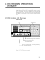
2.1 DSC Controls, LED Warnings
DSC controls
DSC controls
LCD
VHF RADIOTELEPHONE FM-8700
POSITION AUTO ACK
Watch VHF ch70
auto
1
PRINT
DISTRESS CANCEL
DISTRESS
VOLUME
(PUSH)
OFF
SQUELCH
OFF/DW/SCAN(PUSH)
ALARM
STOP
LOW
TX
HI
LOW
CH16
CALL
CHANNEL
REM USA WX PRIV MODE(PUSH)
2
TEST
3
CANCEL
CONTRAST VOLUME
4
5
6
FILE
RCVD
XMTD
7
8
9
0
SELECT
ENT
AUTO
Transmits messages other than distress.
Silences the receive alarm.
Stops repetitive alerts.
Transmits the distress alert. Press the [DISTRESS]
key 4 seconds continuously.
Figure 2-1 FM-8700 transceiver unit
2-1
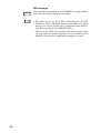
LED warnings
DISTRESS
ALARM
STOP
2-2
The four LEDs surrounding the [DISTRESS] key light continuously when the distress signal is transmitted.
• The upper two of the four LEDs surrounding the [ALARM
STOP] key blink (and alarm sounds) when distress or urgent
message is received. LEDs can be extinguished and alarm silenced by pressing the [ALARM STOP] key.
• The lower two LEDs (Green) blink (and alarm sounds) when
message other than distress/urgent are received. Alarm is automatically silenced five seconds after message is received.
DSC control description
POSITION AUTO ACK
1
PRINT
2
3
CANCEL
CONTRAST VOLUME
4
5
6
FILE
RCVD
XMTD
7
8
9
0
Key
0
TEST
Figure 2-2 DSC keyboard
SELECT
ENT
Function/Purpose
9
CANCEL
Enter numeric data.
Cancels wrong data and restores previous menu.
Adjusts illumination of LED and keys in four levels.
SELECT
1. Displays Set up menu (Main menu).
2. Changes settings of items appearing with blinking question mark.
ENT
Registers key input. (Blinking item is registered when key is pressed.)
1. Shifts the cursor leftward.
2. Restores previous display when pressed at displays with a blinking
question mark.
Shifts the cursor rightward.
POSITION
1
AUTO ACK
2
Position and time are shown while pressed and held down.
Turns automatic transmission of acknowledge call (AUTO ACK) on/off. (Refer
to page 2-8.) Note that distress alert cannot be automatically acknowledged
by "auto acknowledge."
TEST
3
Conducts self-tests.
PRINT
4
Printing. (Also sets up automatic printing.)
CONTRAST
5
Adjusts contrast of LCD in eight levels.
FILE
7
RCVD
8
XMTD
9
VOLUME
Opens files.
Displays contents of received messages. (Storage capacity: 100 files, 50
each of distress and other.) (Refer to page 4-20.)
Displays contents of transmitted messages. (Storage capacity: 50 files.)
(Refer to page 4-20.)
Not used.
6
2-3
2.2 DSC Operational Overview
Standby display
When the FM-8700 is turned on, the following display appears.
This display is known as the “standby display.” This is where you
will begin most operations.
Watch VHF CH70
Standby display
screen
auto
[2] key pressed to get "auto" screen.
Should you get lost in operation you can return to the standby display by pressing the [CANCEL] key several times.
Selecting and registering items
The arrow keys ([t] and [s]) function to select items on the LCD.
After selecting item, press the [ENT] key to register it.
Item selected by cursor
appears here.
Call type <ALL ships>
Blinking
cursor
IND TEL ALL R/A --encloses
current
selection. (Scrolls
(Scrolls
screen
screen
leftward.)
rightward.)
Call type
selection screen
Press the [ENT] key.
When blinking question mark appears
Press the [ENT] or [SELECT] key depending on your desire.
Blinking question mark
* VHF call message *
Format ? INDIVIDUAL
If change is necessary
press the [SELECT] key.
2-4
Format selection screen
(In this example it is format
for "VHF call message.")
If no change is necessary,
press the [ENT] key.
Preparing and transmitting DSC messages
There are two methods by which you can prepare and transmit
DSC messages, and they are shown below.
Preparing message for immediate transmission
Prepare message and then transmit it as follows:
Standby display
Press the [ENT] key.
* VHF call message *
Format? INDIVIDUAL
For how to prepare a DSC message,
refer to page 4-1.
After preparation, press the [CALL]
key to transmit the DSC message.
Transmitting a message stored in the memory
99 messages (excluding distress message) can be saved to the
memory. You may open a memory-stored message and transmit it
as follows:
Standby display
Press the [SELECT] key.
Set up menu <
1
2
3
4
>
6
7
9 ALM
Press the [7] key.
For how to prepare and store a message, refer to "4.5 Preparing
and Saving Messages."
After the standby display appears, press keys in the order
shown below to transmit a DSC messages.
Press the [7] key. / (Enter file number.) / Press the [CALL] key.
2-5
Distress alert transmission and output power
When the distress alert is transmitted (by pressing the [DISTRESS]
key), the output power of the FM-8700 is automatically set to maximum (25 W).
When keyboard input is prohibited
The DSC section keyboard accepts no key input while a DSC message is being transmitted. (DSC keyboard is inoperative about 3
seconds during a DSC distress call; 0.5 seconds for other DSC
calls.)
2-6
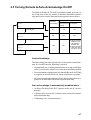
2.3 Turning Remote & Auto Acknowledge On/Off
To enable or disable AUTO ACK and remote control, press the [2}
key. Each press of the key enables or disables automatic acknowledge and remote control function in the sequence shown below.
Automatic
acknowledge
Watch
Auto
Press [2] key
Remote control function
At transmission
with [CALL] key At reception
pressed
ON
ON
ON
ON
ON
OFF
Watch
Manual
Press [2] key
Watch
OFF
Limit
ON
1) When receiving
all ships call or
call related to
distress: ON
2) When receiving
calls other than
the above: OFF
Press [2] key
Limit acknowledge
The limit setting provides restricted use of the remote control function. It is useful when the following is desired:
• Automatically set a working channel when receiving an All Ships
call so as not to miss initial voice from the transmitting station.
• Prevent automatic transmission of acknowledge back (ACK BQ)
in response to an individual call, when no operator is present.
• Prevent automatic transmission of own ship position data in response to an individual call which requests such data.
Auto acknowledge is automatically disabled when…
• An Error Checking Code (ECC) appears at the end of a receive
message.
• A distress alert is received. (A distress alert cannot be acknowledged automatically.)
• Conducting voice communications.
2-7
This page is intentionally left blank.
3. DSC DISTRESS COMMUNICATIONS
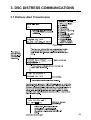
3.1 Distress Alert Transmission
1
2
3-1
(from previous page)
* Received * DISTRESS ACK
ID : 001234567
ID of station (usually coast station)
which transmitted DIST ACK.
Commence voice communications with coast station on CH16.
1. Provide the following information to the coast station:
Distress call
(1) Speak slowly and distinctly, “MAYDAY, MAYDAY, MAYDAY,” pronounced as the French expression “m’aider.”
(2) This is;
(3) The name of your vessel and call sign three times.
Then, begin the distress communications, which consists of:
Distress communications
(1) Position in latitude and longitude;
(2) The name of the distress;
(3) The kind of assistance desired;
(4) Any other information which might facilitate rescue, for
example, length, color, and type of vessel, number of persons on board.
2. Indicate the end of message by saying “Over.”
Some countries do not have sea area A. In this case “ACK” from
the coast station does not arrive over DSC. A ship nearby will contact the vessel in distress over CH16. After transmitting the distress alert, conduct voice distress communications as shown above.
3-2
3.2 Manual Entry of Ship’s Position and Time
Entering data manually
If automatic position input is lost for one minute the message "EPFS
error" appears. In this case, enter position manually as below.
(Normal display)
* VHF call message *
Format: DISTRESS
Watch VHF CH70
To enter data manually
from the Distress Alert
message, press [ENT]
and select call type
Distress.
Press the [SELECT] key
followed by the [1] key.
Press [ENT], [ENT]
[SELECT] in this order.
Position <
NORTH=
°
Enter
latitude.
>
S
E=
°
Enter
longitude.
To move blinking cursor from NORTH
position to SOUTH, press the [s] key.
W
UTC=
:
Enter time
(UTC).
Press the [ENT] key.
(Returns to normal
display.)
Note: If the manually entered position is not updated within four
hours the buzzer sounds and the message "Warning: Update position!" appears on the screen. And if not updated within 23.5 hours
the position entered is erased. Once automatic input of position is
restored, cancel manually entered position as below.
Confirming Ship's Position and Time
Press and hold down the [1] (POSITION) key, ship's position and
time are shown while the key is pressed.
Canceling manually entered data
To cancel the manually entered data, enter 9999 for the time and
press the [ENT] key.
Note: Above procedure may also be used when you do not know
your ship's position. This data is input as NO INFORMATION in
POS&TIME in the DISTRESS ALERT MESSAGE.
3-3
3.3 Canceling a Distress Call
Within five seconds after pressing the [DISTRESS]
key
If the [DISTRESS] key is pressed by mistake, press the [ALARM
STOP] key immediately (within 5 seconds). The distress call will
be canceled.
[ALARM STOP] key
* Ready for calling *
DISTRESS CALL
CH70
DISTRESS CANCEL
DISTRESS
ALARM
STOP
LOW
TX
HI
LOW
CH16
CALL
CHANNEL
REM USA WX PRIV MODE(PUSH)
Figure 3-1 ALARM STOP key
If more than five seconds elapses after the
[DISTRESS] key is pressed
1. Switch off equipment immediately.
2. Switch equipment on and set to Channel 16.
3. Transmit message to “All Stations” giving your vessel's name,
callsign and DSC number to cancel the distress alert.
Example message
All Stations, All Stations, All Stations
This is VESSEL'S NAME, CALLSIGN,
DSC NUMBER, POSITION.
Cancel my distress alert of
DATE, TIME, UTC.
=Master, VESSEL'S NAME, CALLSIGN.
DSC NUMBER, DATE, TIME UTC.
3-4
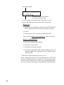
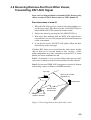
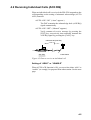
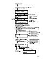
3.4 Receiving Distress Alert from Other Vessel,
Transmitting DIST ACK Signal
In no case is a ship permitted to transmit a DSC distress relay
call on receipt of a DSC distress alert on VHF channel 70.
Procedure when in area A1
1. When the FM-8700 receives a distress alert from another vessel the upper two LEDs (Red) near the [ALARM STOP] key
blink and the FM-85700 sounds the distress alarm.
2. Silence the alarm by pressing the [ALARM STOP] key.
3. Wait up to three minutes until the DIST ACK signal from a
coast station is received. Be prepared to follow the instructions
of the coast station.
4. If you do not receive the DIST ACK signal, follow the flow
chart shown on the next page.
If further DSC alerts are received from the same source and the
ship in distress is beyond doubt in the vicinity, a DSC
acknowledgement may, after consulation with an RCC or Coast
Station, be sent to terminate the call.
Note 1: An asterisk (*) in a received distress alert message indicates error or unknown at the location marked with the asterisk.
Note 2: Do not send DISK ACK in response to receipt of distress
alert having a nature of distress of EPIRB emission.
Your Ship
About 20 to 30 miles
(Sea area A1)
Coast station
Distress Alert
Transmission
Vessel in Distress
Figure 3-2 Receiving distress alert from other vessel
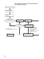
3-5
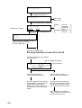
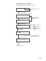
Flow chart for determining if you should/should not
transmit DIST ACK signal
DSC Distress alert received.
Press [ALARM STOP]
key to silence alarm.
Listen on CH16 for
5 minutes.
Did you receive
acknowledge from
CS and/or RCC?
No
Is distress traffic
in progress?
Yes
Yes
Is own
vessel able
to assist?
No
CS = Coast Station
RCC = Rescue Co-ordination Center
Enter details in log.
3-6
No
Is distress call
continuing?
No
Yes
Yes Acknowledge the alert by
radiotelphony to the ship
in distress on VHF CH16.
1. Say "MAYDAY" ONCE.
2. Say ID number of vessel
in distress THREE TIMES.
3. Say "This is" ONCE.
4. Say ID number of your vessel
THREE TIMES.
5. Say "Received MAYDAY"
ONCE.
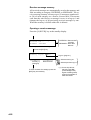
Inform CS and/or RCC.
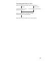
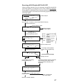
Transmitting DIST ACK over CH16
Select VHF CH16 and transmit DIST ACK to vessel in distress.
No reply
Transmit DIST ACK to vessel in
distress over DSC CH70.
Reply received
Communicate with vessel in distress.
Relay the distress alert to a coast station over DSC.
Follow the instructions of the coast station.
Begin search and rescue operation for the vessel in distress.
3-7
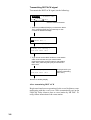
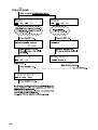
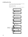
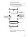
Transmitting DIST ACK signal
To transmit the DIST ACK signal, do the following:
* Received * DISTRESS CALL
ID:
CH70
ID of vessel in distress
1 Press the [ALARM STOP] key to silence the alarm.
Then, press the [ENT] key successively to view
contents of distress message.
Acknowledge call <
>
ACK RELAY END --Press the [ENT] key.
* Ready for calling *
DIST ACK CALL
CH70
2 If you do not receive DIST ACK from coast station
within three minutes and your vessel meets
requirements (see previous page) for transmitting
DIST ACK, press the [CALL] key to transmit the
DIST ACK.
* Call in progress *
DIST ACK CALL
CH70
(Displayed while your
vessel is transmitting
DIST ACK.)
Returns to standby display.
After transmitting DIST ACK
Begin search and rescue operations for the vessel in distress, communicating with the vessel over CH16 (automatically set) on the
FM-8700. Relay distress alert to coast station by MF DSC. Finally, follow instruction of the coast station.
3-8
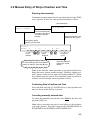
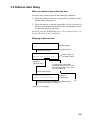
3.5 Distress Alert Relay
When you should relay a distress alert
You may relay a distress alert in the following conditions;
1 When the station in distress is not itself in a position to transmit the distress message, or
2 When the master or person responsible for the vessel not in
distress, or the person responsible for the coast station, considers that further help is necessary.
DO NOT press the [DISTRESS] key to relay a distress alert; it is
for use when own vessel is in distress.
Relaying a distress alert
Watch VHF CH70
(Standby display)
auto
Press the [ENT] key followed by the [SELECT] key.
(To select call type.)
Call type <
>
IND TEL ALL R/A R/S DST
Relay/ALL
(All Ships Call)
Refer to page 5-1
for detail of items.
To call specific coast station
(individual call), select R/S and
press the [ENT] key. Then, enter
the coast station ID.
Press the [ENT] key.
* VHF Call message *
Format: DIST RELAY ALL
(Display for
All Ships Call)
Press the [ENT] key followed by the [SELECT] key.
(To enter ID of vessel in distress.)
(*1)
(continued on next page)
3-9
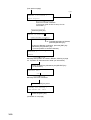
(from previous page)
(*1)
Address < No inform >
input digits=
Enter ID of vessel in distress.
(If not know, enter all "9s" to set up for No
information.")
Press the [ENT] key.
Nature of distress?
UNDESIGNATED DISTRESS
To designate nature of distress,
press the [SELECT] key.
If nature of distress is unknown, press the [ENT] key
followed by the [SELECT] key.
(To enter position of vessel in distress.)
Position <
>
NORTH=
Manually enter position of vessel in distress, referring to page
3-4. If position is unkmown enter "9999" (no information).
Press the [ENT] key followed by the [SELECT] key.
(To enter time.)
Distress UTC:
UTC?
Manually enter time of distress.
Press the [ENT] key twice.
* Ready for calling *
DIST RELAY ALL
CH70
Press the [CALL] key.
(continued on next page)
3-10
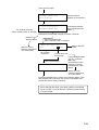
(from previous page)
DISTRESS RELAY ALL
Dist ship ID:
* Call in progress *
For All Ships Call only
(When selecting "R/A" in call type.)
DISTRESS RELAY ALL
(Distress ship ID
appears on second line.)
(Transmitting distress
relay to all ships/coast
station.)
Distress alert transmitted (relayed) for about 3 seconds.
Returns to
standby display.
Only for individual Call
(When selecting R/S in call type.)
* Wait for relay ack *
Watch on CH16,
following instructions
of a coast station.
Dist:
ID of vessel
in distress
4.8 min
Wait for relay ack
screen
Counts down from
five minutes.
If not acknowledged,
* No ack call received *
If acknowledged within
five min., press the
[ENT] key
successively to view
contents of receive
message from coast
station.
Watch on CH16,
following instructions
of a coast station.
Press the [CANCEL] key to return to the standby display. Then,
relay distress call by all ships call, contact coast station, and
search and rescue vessel in distress.
After relaying the alert, you must conduct search and
rescue for the vessel in distress, following instructions
of coast station.
3-11
This page is intentionally left blank.
4. DSC OPERATION FOR
NON-DISTRESS CASES
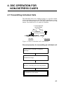
4.1 Transmitting Individual Calls
The individual call is for sending message to a specific station.
After transmitting message (called ACK RQ transmission), wait to
receive the acknowledge back (ACK BQ) signal from receiving
station. You should receive it within five minutes.
2 Acknowledge back
(ACK BQ signal)
1 Individual call
(ACK RQ transmission)
Own Ship
Coast Station
Figure 4-1 How an individual call is transmitted
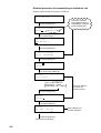
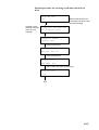
General procedure for transmitting an individual call
Load saved Tx message, or prepare
message.
Transmit message.
Receive ACK BQ from receiving station.
Communicate with station.
4-1
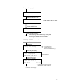
Detailed procedure for transmitting an individual call
Prepare and transmit a message as follows:
Watch VHF CH70
Press the [ENT] key.
Previously selected
format appears here. If
“INDIVIDUAL” appears,
press the [ENT] key.
* VHF call message *
Format?
Press the [SELECT] key.
(To select format.)
Call type <
>
IND TEL ALL --Place the cursor on “IND”.
Press the [ENT] key.
* VHF call message *
Format: INDIVIDUAL
Press the [ENT] key.
Address?
Category:
Press the [SELECT] key.
(To enter other station ID.)
Address <
>
input digits =
Entry of other station ID
Ship station: 9 digits
Coast station: 00 + 7 digits
Press the [t] key.
(To return to
previous menu.)
Press the [ENT] key.
Address:
Category?
Press the [SELECT] key.
(To select category.)
Category <
DIS
URG
>
SAF
ROU
Select “ROU”.
Press the [ENT] key.
(continued on next page)
4-2
“ROU” (Routine) is
normally selected.
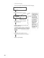
(from previous page)
Telecom1??
Telecom2:
Press the [SELECT] key.
(To eselect telecommand 1.)
Telecom1 <
SMP
Dup
>
DAT
Usually select SMP or DUP .
FAX
NO
Select mode desired.
Press the [ENT] key.
Channel?
Press the [SELECT] key.
Note; Working channel is normally set by coast
station. Therefore, set up for "No information"
by setting the working channel as 9999.
Working channel <
>
input digit =
Enter channel followed by
[ENT] key.
To cancel message
prepared, press the
[CANCEL] key.
(Return to normal display.)
* Ready for calling
INDIVIDUAL CALL CH70
Press the [CALL] key.
* Call in progress
(Transmitting)
INDIVIDUAL CALL CH70
Transmission time
about 0.5 seconds
* Wait for ack BQ *
Next CH70
5.0 min
Continued on next page.
Counts down from five minutes.
Regulations prohibit calling to
same station during this time.
4-3
(From previous page)
After receiving the ACK BQ signal, do the following:
* Wait for ack BQ *
Next CH70
When the ACK BQ signal is received;
ABLE:
Receiving station
accepts working
channel proposed
by your ship.
* Received *
ACK BQ
UNABLE: "16" is displayed
when other ship
ID:
ROUTINE
rejected working
channel proposed
by your ship. If
Received station ID
coast station was
called, however,
1Alarm sounds. To silence, press the
the LCD shows
[ALARM STOP] key.
"QUEUE INDICATION,"
meaning the coast
station is busy.
2If "ABLE" appears, communicate with other
Wait on channel
station over the VHF.
designated; the
coast station will
If "UNABLE" appears, prepare a message with
contact you.
different proposal and transmit it by pressing the
[CALL] key. Repeat until proposal is mutually
accepted.
3If you want to view contents of receive
message, press the [ENT] key successively.
Returns to normal display.
4-4
4.2 Receiving Individual Calls (ACK RQ)
When an individual call is received, the FM-8700 responds to the
call depending on the setting of automatic acknowledge (AUTO
ACK) function:
• AUTO ACK “ON” (“Auto” appears.)
The DSC transmits the acknowledge back (ACK BQ)
signal automatically.
• AUTO ACK “OFF” (“Manual” appears.)
Verify contents of receive message by pressing the
[ENT] key successively, then manually transmit the
ACK BQ signal by pressing the [CALL] key.
Individual call (ACK RQ)
Own Ship
Coast Station
Figure 4-2 How to receive an individual call
Setting of “ABLE” or “UNABLE”
When AUTO ACK function is ON, you can select either “able” or
“unable” (to comply) for proposal from other station. See the next
page.
4-5
Watch VHF CH70
Press the [SELECT] key.
(To diaplay Setup menu.)
Set up menu <
>
Setup menu
(Main menu)
1 2 3 --Select 2 followed by the [ENT] key.
ABLE:
Comply status <
Normally set to ABLE.
UNABLE
>
ABLE
Press the Press the [ENT] key.
[ENT] key.
Unable <
To accept
proposal of
transmitting
station.
UNABLE: Proposal is not
accepted.
>
NOR BSY --Select reason why unable to comply.
(Normal setting: No reason)
Press the [ENT] key.
Returns to standby display.
Receiving individual call with AUTO ACK ON
Automatic transmission of ACK BQ
(Alarm sounds.).
ABLE or UNABLE appears.
* Auto ack *
Other station ID
ID:
When "able to comply" is
selected.("ABLE" appears.)
When "unable to comply" is
selected. ("UNABLE" appears.)
Since the channel of the FM-8700
is automatically set to the channel
designated by a transmitting
station, voice communication can
be initiated by you or transmitting
station.
The channel of the FM-8700 is
restored to the previous channel.
(The channel is diffrent from the
one designated by other station.)
Then, prepare a message with
diffrent proposal and transmit it by
pressing the [CALL] key.
4-6
Receiving ACK RQ with AUTO ACK OFF
After verifying contents of receive message, manually transmit the
ACK BQ signal by pressing the [CALL] key within five minutes.
If the signal is transmitted more than five minutes after reception
of ACK RQ signal, it is treated as an ACK RQ signal rather than an
ACK BQ signal.
Other ship ID
* Received * ACK RQ
ID:
Alarm sounds. To silence, press the [ALRAM STOP] key.
Press the [ENT] key.
Communication mode
DUPLEX TP
No information
Channel:
Confirm proposal
from other station.
Working channel
ACK: Transmits ACK BQ
signal.
END: Returns to normal
display.
NEXT: Recalls received
message.
DEL: Deletes received
message from
memory.
Press the [ENT] key twice.
Acknowledge call <
>
ACK END NEXT DEL
Press the [ENT] key.
* Acknowledge call *
Communication mode
Telecom1? DUPLEX TP
To change communication
mode, press the [SELECT]
key.
Press the [ENT] key.
Channel?
(*1)
(continued on next page)
Working channel
If no change is necessary,
press the [ENT] key.
To change working channel, press the
[SELECT] key then enter desired
channel number followed by the
[ENT] key.
* Ready for calling *
ACK BQ CALL
CH70
To transmit the ACK BQ signal, press
the [CALL] key.
Then, communicate
with other station.
Returns to standby display.
4-7
4-8
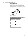
4.3 Transmitting All Ships Calls
Purpose of all ships call
The All Ships Call is used to transmit important ship’s safety message, safety of life at sea message or meteorological warning.
After transmitting message, you can communicate by voice over
the FM-8700.
Coast Station
Own Ship
Figure 4-3 All ships call
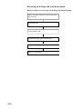
General procedure for transmitting an all ships call
Open file to transmit, or prepare message.
Press the [CALL] key.
Begin voice communications.
The procedure for voice communication is shown on the next page.
4-9
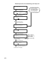
Detailed procedure for transmitting an all ships call
Watch VHF CH70
auto
Previously selected
format appears here. If
"ALL SHIPS" appears,
press the [ENT] key.
Press the [ENT] key.
* VHF call message *
Format?
Press the [SELECT] key.
(To select format.)
Call type <
>
IND TEL ALL ---
Place the cursor on "ALL."
Press the [ENT] key.
* VHF call message *
Format: ALL SHIPS
Press the [ENT] key.
Category?
Telecom1:
Press the [SELECT] key.
(To select category.)
Category <
DIS: Distress
URG: Urgency
SAF: Safety
ROU: Routine
>
DIS URG SAF ROU
Select category desired.
(example: SAFety)
Usually select priority higher
than "SAF."
Press the [ENT] key.
Category: Safety
Telecom1?
Press the [SELECT] key.
(To select telecommand 1.)
(continued on next page)
4-10
(from previous page)
Telecom1 <
SMP
To return to
previous menu,
press the [t] key.
DUP
>
DAT
Usually select "SMP."
---
Select communication mode desired.
(Example: Simplex)
Press the [ENT] key.
Telecom2: No information
Channel?
Press the [SELECT] key.
(To enter working channel.)
Working channel <
input digits =
>
16
Channel entry (Example: 16)
Press the [ENT] key.
* Ready for calling *
ALL SHIPS CALL CH70
To cancel message
prepared, press the
[CANCEL] key.
Press the [CALL] key.
(To transmit call.)
* Call in progress *
Returns to normal display.
ALL SHIPS CALL CH70
Transmission time
about 0.5 seconds
Returns to standby display.
CH70 is automatically selected,
and the message
prepared here is
transmitted.
CH16 (designated above) is automatically selected,
so you can commence voice communications
immediately.
4-11
4.4 Receiving All Ships Calls
When an all ship’s call is received while conducting voice communications, press [2] (AUTO ACK) to switch to VHF channel.
The all ship’s call, transmitted by coast station or ship station, provides navigation and weather alerts and emergency information.
Status of FM-8700 when receiving an all ships call
Handset
status
When an all ship's call is received
On hook (*)
1. Equipment automatically switches to working
channel.
2. Caller's voice can be heard.
Off hook (*)
1. Alarm sounds.
2. Press [2 ](AUTO ACK) key to switch to working
channel.
3. Caller's voice can be heard.
* On hook: Handset hung in hook.
Off hook: Handset picked up.
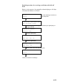
Receiving an all ships call in on hook status
Basic procedure for receiving an all ships call while on hook
Watch DSC distress/safety channel.
Receive All Ships Call.
VHF channel is automatically selected.
Listen to message.
4-12
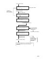
Detailed procedure for receiving an all ships call while on
hook
Watch VHF CH70
auto
Channel is automatically changed.
Listen to voice
message.
Below is the sequence for
receiving an All Ships Call in
auto acknowledge.
* Received * ALL SHIPS CALL
ID: 007654321 Safety
Press the [ENT] key.
SIMPLEX NO INFORM
Channel: CH25
Press the [ENT] key.
EOS: EOS
ECC: OK
Press the [ENT] key.
Receive call <
END
NEXT
>
DEL
Select END and press the [ENT] key.
Watch VHF CH70
auto
End
4-13
Receiving an all ships call in off hook status
Basic procedure for receiving an all ships call while off hook
Notice of All Ships Call arrives while communicating
with other ship.
Watch DSC CH70.
Receive All Ships Call.
Press [ALARM STOP ] key to silence alarm.
Press the [2] key.
Listen to voice message.
4-14
Detailed procedure for receiving an all ships call while off
hook
Below is the sequence for manually acknowledging an all ships
call when the handset is off hook.
Watch
Do the following to receive an
All Ships Call.
manual
* Received * ALL SHIPS CALL
ID: 007654321 Safety
Press the [2 (AUTO ACK)] key followed by the [ENT] key to
change channel.
SIMPLEX NO INFORM
Channel: CH25
Press the [ENT] key.
EOS: EOS
ECC: OK
Press the [ENT] key.
Receive call <
END
NEXT
>
DEL
Select END and press the [ENT] key.
Watch
manual
Listen to contents of message.
4-15
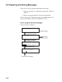
4.5 Preparing and Saving Messages
There are two ways to prepare and transmit a message:
1. Prepare a message for immediate transmission. (Refer to
page 4-1.)
2. Prepare a message and store it for later transmission.
You can save up to 59 transmit messages (excluding distress messages) to the memory. These are numbered 01 to 59.
How to prepare transmit messages
Prepare message as follows:
Watch VHF CH70
(Standby display)
Press the [SELECT] key.
(To display Setup menu.)
Set up menu <
>
1 2 3 --Press the [7 (FILE)] key.
(To display File menu.)
File <
>
MESSAGE ADDRESS TEL No.
Press the [ENT] key.
* VHF call message *
Format?
(continued on next page)
4-16
Setup menu
(Main menu)
s
t
4-17
4.6 Writing Over Files
You may write over unnecessary files. Simply prepare a message
and store it under file number of unnecessary file.
How to write over files
Example: You want to write over file saved under file number 01.
Watch VHF CH70
Press [SELECT], [7] and
[ENT] key in that order.
* VHF call message M *
Format?
Prepare a message (see page 4-1).
* Ready for filing *
Press the [ENT] key.
Call message <New>
02/59:
Press the [t] key to display "01."
Call message <
>
01/59: A1
File name
Press the [ENT] key.
Name < A1 >
END
Enter new name,
referring to
previous page.
ABCDEFG
If you don t want to change file name,
press the [ENT] key.
* Same file name exists *
Duplicate name?
YES
NO
Press the [ENT] key.
(To write over existing file.)
Next file memory <End>
END
4-18
NEXT
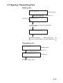
4.7 Opening, Transmitting Files
Opening a file
Watch VHF CH70
(Standby display)
Press the [7 (FILE)] key. / (Enter file no.)
/ Press the [ENT] key.
File name
Call message <
>
/59:
To view contents of message, press the [ENT]
key successively.
* Ready for calling *
To transmit message:
Press the [CALL] key
To return to standby display: Press the [CANCEL] key.
Transmitting a file
Watch VHF CH70
(Standby display)
Press the [7 (FILE) ] key. / (Enter file no.)
/ Press the [CALL] key.
* Call in progress *
(Transmitting)
Returns to standby display.
4-19
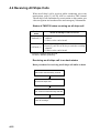
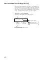
4.8 Transmit/Receive Message Memory
The transmit message memory stores up to 50 transmitted messages (numbered 1 to 50) on a first-in, first-out basis. This means
each time you save a transmitted message it is filed as log no. 1
and the log no. of all previously stored transmit messages changes
by one. When the memory is full the oldest file is deleted.
Opening a transmit message
Press the [9 (XMTD)] key at the standby display.
Xmitted log No. <1/50>
Log no. (page number)
: Selects next log no.
Format
(Call type)
Time
transmitted
To view contents of message, press the
[ENT] key successively.
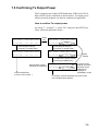
4-20
: Selects previous log no.
Transmitting retrieved message
You can transmit a retrieved message as follows:
Xmitted log No. <1/50>
Select page by the arrow
keys.
Press the [ENT] key.
[Example: Individual message is retrieved.]
AD:
Routine
DUP TP
No infor
Press the [ENT] key.
Press the [t] key.
(To return to previous
menu.)
Channel:
EOS: ACK RQ
Press the [ENT] key.
Call again <
CALL
END
NEXT
>
DEL
Select "CALL."
Press the [ENT] key.
END: Returns to normal
display.
NEXT: Recalls transmitted
message.
DEL: Deletes transmitted
message from
memory.
Channel?
To change working channel,
press the [SELECT] key.
Press the [ENT] key.
* Ready for calling *
INDIVIDUAL CALL CH70
Press the [CALL] key.
4-21
Receive message memory
All received messages are automatically saved to the memory and
filed according to category, DISTRESS or ORDINARY. The receive message memory can store up to 50 messages (numbered 1
to 50) of each category on a first-in, fist-out basis. This means
each time the unit receives a message it saves it as log no.1 and
changes the log no. of all previously received messages by one.
When the memory is full the oldest file is deleted.
Opening a receive message
Press the [8 (RCVD)] key at the standby display.
Received call <
DISTRESS
>
ORDINARY
DISTRESS: Distress alert
received
ORDINARY: Other than
distress
For example, “ORDINARY” log;
Press the [ENT] key.
Ordinary log No. <1/50>
Log no. (page no.)
: Selects next log no.
Format (*1)
(Call type)
Data received
To view contents of message, press the
[ENT] key successively.
4-22
: Selects previous log no.
(*1): If own ship did not
transmit “ACK BQ”
(acknowledge back)
signal a blinking sharp
symbol (#) appears at
head of Format.
Transmitting retrieved message
You can send the acknowledged call (DIST ACK or ACK BQ)
under certain conditions after retrieving a received message. Refer
to page 3-5 for transmitting the DIST ACK signal.
Example: Transmit acknowledge back (ACK BQ) signal in response
to an individual call (Refer to page 4-5.)
Received call <
DISTRESS
>
ORDINARY
Select "ORDINARY," then press the [ENT] key.
Ordinary log No. <1/50>
To view contents of message,
press the [ENT] key successively.
Acknowledge call <
ACK
Press the [t] key.
(To return to
previous menu.)
END
NEXT
DEL
Press the [ENT] key.
* Acknolege call *
Telecom1?
>
Select "INDIVIDUAL"
number desired by the
arrow keys.
END: Returns to normal
display.
NEXT: Recalls received
message.
DEL: Deletes received
message from
memory.
To change, press the
[SELECT] key.
Press the [ENT] key.
Channel?
To change, press the
[SELECT] key.
Press the [ENT] key.
* Ready for calling *
ACK BQ CALL
CH70
Press the [CALL] key to transmit the ACK BQ signal.
Note: If the ACL BQ signal is transmitted more than five minutes
after reception of ACK RQ signal, it is treated as an ACK RQ signal rather than ACK BQ.
4-23
This page is intentionally left blank.
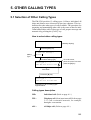
5. OTHER CALLING TYPES
5.1 Selection of Other Calling Types
The FM-8700 provides 12 calling types. Of these, individual, all
ships and distress were discussed in previous chapters. This section describes the other types of calls available. The procedure for
preparing and transmitting other calls is the same as that for individual and all ships calls: Select type of call, prepare message and
transmit it by pressing the [CALL] key.
How to select other calling types
Watch VHF CH70
(Standby display)
Press the [ENT] key.
* VHF call message *
Calling
Type
Format?
Press the [SELECT] key.
(To select calling type.)
Call type <
>
To scroll screen,
place the cursor here and
press the [s] key.
IND TEL ALL R/A R/S DIS
Selectable
Press the [s] key.
Call type <
>
GRP GEO POS POL MED NEU
Description of all 12 calling types
appears below.
Calling types description
IND:
Individual call. (Refer to page 4-1.)
TEL:
Telephone call. (Semi-auto/auto call. Refer to page
5-3.) Call a terrestrial network, for example,
through a coast station.
ALL:
All Ships call. (Refer to page 4-9.)
5-1
R/A and R/S: Distress relay for All Ships and for Selective (Individual) calls. (Refer to page 3-9.)
DIS:
Distress call. (Refer to page 3-1.)
GRP:
Group call. Call a specific group by entering group
ID number.
GEO:
Geographic area call. Call for ships within a range
set by you in the transmit message (menu). To designate the range, enter reference point and width
(range) data of both longitude and latitude.
s
s
5-2
s
POS:
Position request (Individual call). Find position
of other ship by entering its ID number.
POL:
Polling call (Individual call). Confirm that own
ship is within communication range with other ship.
This function provides only negative response; it
does not provide position information.
MED:
Medical transport (All ships call). Inform all
ships, by using “urgent” category, that own ship
carries medical goods.
NEU:
Neutral craft (All ships call). Inform all ships by
Urgency or Safety category, that own ship is not a
participant in an armed conflict.
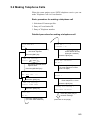
5.2 Making Telephone Calls
When the coast station serves PSTN telephone service you can
make Telephone Call via Coast Station.
Basic procedure for making a telephone call
1. Selection of Format specifier.
2. Entry of Coast Station ID.
3. Entry of Telephone number.
Detailed procedure for making a telephone call
Watch VHF CH70
Coast AD <
auto
7 DIGITS = 00
Press the [2] key successively
until "auto" appears.
>
Coast Station ID Entry
(Example: 1234567)
Press the [ENT] key.
Press the [ENT] key.
* VHF call message *
Coast AD: 001234567
Format?
Tel No.?
Previously selected format
appears here.
Press the [SELECT] key.
Format <
IND
TEL
>
ALL
Telephone number
---
Place the cursor on "TEL."
Press the [ENT] key.
* VHF call message *
Format?
Press the [SELECT] key.
(To enter telephone number
(max. 16 digits.)
DIGITS =
Enter telephone no. here.
Press the [ENT] key.
PSTN CALL
* Ready for calling *
Press the [ENT] key.
Coast AD?
Tel No.
Press the [SELECT] key.
(To enter coast station ID.)
PSTN CALL 001234567
Press the [CALL] key to
transmit message.
(continued on next page)
5-3
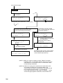
(from previous page)
PSTN CALL
(*)
Immediately
* Call in progress *
* Waiting for ack BQ *
PSTN CALL CH70
AUTO RETRY in 5 sec
(Transmission time is about 0.4 - 0.6 seconds.)
Counts down.
(*)
If ACK BQ from coast station is not
received within five seconds PSTN
call is automatically retransmitted.
If ACK BQ is received, PSTN
CALL (EOS) signal and carrier are
transmitted (NOTE 1).
* Call in progress *
* Call in progress *
AUTO RETRY
CARRIER
CH70
Working channel designated
by coast station.
* Waiting for ack BQ *
5 sec to go
Transmission time is about
two seconds.
* PSTN CALL connected *
Counts down.
To end call: [CANCEL]
If ACK BQ is received;
If ACK BQ is not received;
* No response *
Try again after 15 min
Ringer bell of VHF sounds. Take handset
from VHF hanger and commence voice
communication (see NOTE 2).
Re-call after 15 minutes.
(NOTE 1) When you receive "unable to comply" (BUSY) command
instead of "able," the FM-8500 waits for "Ring back call" from
coast station for 15.5 minutes. Then, if it is received, carrier
is automatically transmitted.
(NOTE 2) If there is no reply (voice response) from subscriber within
one minute at "PSTN CALL connected" display, the
communication line will be disconnected. The display should
look something like the display 2 on the page 5-7.
If you hang the handset on the hanger, the display 1 shown
on the next page appears to break the communication line.
5-4
Operation after making DSC telephone call
Voice communication is started. After completion of communication, the display changes as shown in (1) or (2) below depending
on how voice communication was terminated.
(1) When you end voice communication by pressing the [CANCEL] key or hanging the handset on the hanger of the VHF, the
display of the FM-8700 changes as follows.
Note: If a subscriber hangs the handset on the hanger to
terminate voice communication, coast station will transmit the
“End of call” command to you to break the communication
line.
PSTN CALL
Display 1
Working channel
* Call in progress *
END OF CALL
Transmits "End of call" command.
* Waiting for end call ack *
AUTO RELAY in 2 sec
Counts down.
If "End call ack" is not received
within two seconds;
If "End call ack" is
received;
* Call in progress *
AUTO RETRY
* Waiting for end call ack *
2 sec to go
If "End call ack" is received;
If not received;
* End call not received *
* Received * END OF CALL
No charge information
Charge time:
(No charge time information)
Charge time appears.
5-5
(2) When coast station terminates communication, the display of
the FM-8700 is as follows:
When the "End of call" command from
coast station is received;
* Received * END OF CALL
Display 2
Charge time:
Charge time
appears here.
Note: If a subscriber hangs the handset on the hanger to terminate
voice communications, coast station will transmit the “End of call”
command to you to break the communication line.
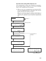
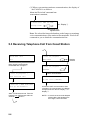
5.3 Receiving Telephone Call from Coast Station
Watch VHF
ch70
auto
* Call in progress *
PSTN CALL
Working
channel
Reply signal is automatically
transmitted after reception.
* Call in progress *
CARRIER
* Call in progress *
PSTN CALL ACK CH70
PSTN CALL (EOS) signal and
carrier is transmitted.
* PSTN CALL connected *
To end call: [CANCEL]
* Auto ack * ABLE PSTN CALL
Pick up the handset!
Alarm of FM-8700 sounds. Take the
handset from VHF hanger within 60
seconds.
NOTE 1
5-6
Commence VHF communication. After
completion of communication, the display
changes as shown above: Display 1 or
Display 2.
NOTE 1: If more than 60 seconds elapses
without taking the handset from
the hanger, call is canceled.
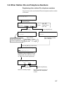
5.4 Other Station IDs and Telephone Numbers
Registering other station IDs, telephone numbers
You can store often-used station IDs and telephone numbers under
a file name.
Watch VHF CH70
Press the [SELECT] key, and
press the [7] key.
File <
>
MESSAGE
ADDRESS
TEL No.
Address: Other Station ID
(max. 99)
Tel No. : Telephone No.
(max. 50)
Press the [ENT] key.
Press the [ENT] key.
Address number <
>
9 DIGITS=
>
DIGITS=
Enter number.
You can receive group
calls having group ID
numbers registered here.
Telephone number <
Ship Station: 9 digits
Coast Station: 00 + 7 digits
Group Call:
0 + 8 digits
Enter telephone number.
(max. 16 digits)
Press the [ENT] key three times.
Name <
END
>
A B C D ---
Assign file name by following the
procedure shown on page 4-16. After
assigning file name, place the cursor
on END then press the [ENT] key.
Next file memory <
END
>
NEXT
Press the [ENT] key.
Returns to standby display.
Press the [ENT] key.
Returns to screen for entry of
other station ID or telephone
number.
5-7
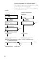
Opening other station IDs, telephone numbers
You can open a file registered on previous page, and use it with the
message which you are currently preparing.
To retrieve a file, first press the [7 (FILE)] key on a display where
the blinking question mark appears.
[Example]
1. Displaying Other Station ID
2. Displaying Telephone Number
Individual Call
Telephone Call
Address?
Channel:
Tel No.?
Blinking
Blinking
Press the [7] key.
Press the [7] key.
Address file <
Coast AD
>
Tel <
Ship AD
Display 2
01/50
Select one. (Example: Coast AD)
Select desired telephone file
number with the arrow keys.
Press the [ENT] key.
Coast AD <
>
>
Display 1
01/99:
File No.
Select desired ID number (file
number) with the arrow keys.
Press the [ENT] key.
Press the [ENT] key.
ID number selected is input into the
transmit message.
Telephone number selected is input
into the transmit message.
Note: Each press of the [SELECT] key at display 1 or display 2 alternates file number
and alphabet-prefixed file name.
Press the [SELECT] key at display 1.
(Alphabetical order)
A1/ZZ:
File Name
Press the [SELECT] key. / (Numeric order)
5-8
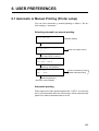
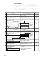
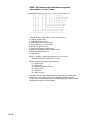
6. USER PREFERENCES
6.1 Automatic or Manual Printing (Printer setup)
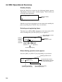
You can select automatic or manual printing as follows. The default setting is “automatic.”
Selecting automatic or manual printing
Watch VHF CH70
(Standby display)
Press the [SELECT] key.
Set up menu <
>
Setup menu (Main menu)
1 2 3 --Press the [4] key.
(To select Print out menu.)
Print out <
AUTO/MANU
>
EEROM
Press the [ENT] key after
selecting "AUTO/MANU."
Print out <
AUTO
>
MANU
AUTO: Automatic printing
MANU: Manual printing
Select either one.
Press the [ENT] key.
Returns to normal display.
Automatic printing
With connection of the optional printer and “AUTO” is selected as
above, all transmitted and received messages will be automatically
printed out when transmitted and received.
6-1
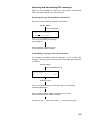
Manual printing
When “Manual” is selected, press the [4 (PRINT)] key to print out
message desired. Note that manual printing is available even when
“AUTO” is selected.
The contents to be printed depend on when the [4] key is pressed,
as shown in the table below.
No.
Printing
Timing of [4] key pressing
Example
Pringout
1
Contents of {VHF call message}
During “VHF call message” display to “Ready
for calling ” display
a
2
Contents of all transmitted logs
{Xmitted log No. <
>}
Displayed [Xmitted log No. < >]
(To stop printing, press the [CANCEL] key.
b
3
Contents of specific log no. (for example,
log no. 1)
{Xmitted log No. <1/50>}
During “[Xmitted…] e Press the [ENT] key.”
display to “EOS” display.
c
Press the [ENT] key.
4
a
Channel?
Call message (again)
Call again
to
CALL END…
Ready for calling
While these
displays
appears
Press the [ENT] key.
5
Contents of all received logs {Ordinary log
(Distress)
No. < >}
Displayed [Ordinary log No. <
>]
(Distress)
(To stop printing, press the [CANCEL] key.)
d
6
Contents of specific log no. (for example,
log no. 1)
{Ordinary log No. <1/50>}
(Distress)
[Ordinary… ] display e Press the [ENT] key.
e
7
* Received *
to
1 Currently received message
While these
displays
appears
ECC: OK
* Received *
Press the [ENT] key.
2 Acknowledge message
Acknowledge call <
“Ready for calling” is displayed.
f
>
8
Contents of currently prepared
{VHF call message M}
During “VHF call message M” display to
“Ready for filing ” diaplay.
g
9
All lists of {saved message} or contents of
all {Address or Tel No.} files.
• Press the [SELECT] key. e
Press the [7] key.
• For example, to print out all coast addresses
in the memory, press the [4] key at display 1
on page 5-9.
h
File <
>
Message Address Tel No.
6-2
Press the [4] key to print out all list of
saved messages.
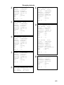
Example printouts
a
Format
Address
Category
Telecom1
Telecom2
Channel
EOS
ECC
:
:
:
:
:
:
:
:
INDIVIDUAL
000000000
Routine
DUPLEX TP
RES No.18
23
ACK RQ
……
DSC ch
: 70
b
***** Xmitted log *****
Xmt message
12:34
Format
: INDIVIDUAL
Address : 004310000
Category : Routine
Telecom1 : DUPLEX TP
Telecom2 : RES No.18
Channel : 23
EOS
: ACK BQ
DSC ch
c
Xmt message
00:09
: INDIVIDUAL
Format
Address : 004310000
Category : Routine
Telecom1 : DUPLEX TP
Telecom2 : RES No.18
Channel : 23
EOS
: ACK RQ
DSC ch
e
f
e
d
: 70
DSC ch
: 70
Format
Address
Category
Telecom1
Telecom2
Channel
EOS
:
:
:
:
:
:
:
DSC ch
: 70
INDIVIDUAL
431000001
Routine
DUPLEX TP
RES No.18
23
ACK BQ
**** Call message file ****
01: FURUNO
Individual
02: CAPTAIN
All ships
***** Ordinary log *****
Rcv message
02:04
Format
: ALL SHIPS
Category : Safety
Telecom1 : SIMPLEX TP
Telecom2 : RES No.18
Channel : 16
EOS
: EOS
ECC
: OK
DSC ch
Rcv message
00:07
Format
: INDIVIDUAL
Address : 431000001
Category : Routine
Telecom1 : DUPLEX TP
Telecom2 : RES No.18
Channel : 23
EOS
: ACK RQ
ECC
: OK
: 70
: 70
Xmt message
02:03
: INDIVIDUAL
Format
Address : 004310000
Category : Safety
Telecom1 : SIMLEX TP
Telecom2 : RES No.18
Channel : No information
: ACK RQ
EOS
: OK
ECC
g
DSC ch
: 70
Format
Address
Category
Telecom1
Telecom2
Channel
EOS
ECC
:
:
:
:
:
:
:
:
DSC ch
: 70
INDIVIDUAL
000000000
Routine
DUPLEX TP
RES No.18
23
ACK RQ
OK
6-3
6.2 Turning Key Beep On/Off
You can turn on/off the beep tone which sounds when a key is
pressed.
Watch VHF CH70
auto
Press the [SELECT] key.
Set up menu <
>
1 2 3 4 6 7 9 ALM
Press the [6] key.
Keyboard click <
>
ON
OFF
Select ON or OFF and press
the [ENT] key.
Standby display appears.
6-4
6.3 Alarm Setup
The receive alarm, which sounds when messages other than distress and urgency are received, may be turned on or off. Furthermore, the distress (and urgency) alarm tone may be selected.
How to turn receive alarm on/off, select distress
alarm tone
Watch VHF CH70
auto
Press the [SELECT] key.
Set up menu <
>
1 2 3 4 6 7 9 ALM
Press the [ALARM STOP] key, or select ALM
followed by the [ENT] key.
To turn the receive alarm on or
off, select ON/OFF. To select
distress alarm tone, select TYPE.
Alarm
ON/OFF
TYPE
Press the [ENT] key.
Ordinary alarm <
ON
>
OFF
Select ON or OFF and
press the [ENT] key.
Standby display appears.
Press the [ENT] key.
Distress alarm type <
>
1 2 3 4 5 6 7 8 9
Select desired distress alarm
tone and press the [ENT] key.
Standby display appears.
6-5
This page is intentionally left blank.
7. SYSTEM CONFIRMATION
7.1 Confirming Own Ship’s ID
Own ship’s ID can be confirmed as follows:
How to confirm own ship's ID
Watch VHF CH70
auto
Press the [SELECT] key.
Set up menu
1 2 3 4
6 7
9
ALM
Press the [9] key, or the [s] key seven times and the [ENT] key.
System <
>
Screen 1
V P ID DSC RT CH PO L
Select "ID" and press the [ENT] key.
* Own indentificaion No. *
protected MMSI: 123456789
Own ship’s ID
To escape, press the [CANCEL] key three times.
7-1
7.2 Confirming ROM Version No.
You can see the ROM version no. (as registered in the memory) as
follows:
How to confirm ROM version no.
At screen 1 previous page, select “V” and press the [ENT] key.
Then, follow the procedure below.
ROM version
RT:1.04
DSC:1.04
To escape, press the [CANCEL] key three times.
RT: VHF section’s ROM version
DSC: DSC section’s ROM version
7-2
7.3 Confirming VHF Section Settings
You can confirm VHF section settings as shown below. To change
VHF section settings, contact FURUNO agent or dealer for service.
How to confirm VHF section settings
At screen 1 on page 7-1, select “RT” and press the [ENT] key.
Then, follow the procedure below.
RT 1-Mode: USA/WX PRIV
protected
Press the [CANCEL] key
to go to previous display.
ON
OFF
Status (ON/OFF) of USA/WX
and PRIV channels
Press the [ENT] key.
RT 2-Hookworking: CH16 SP
protected
ON ON
In on-hook state, CH16 and
speaker status appear.
CH16: ON>Automatically switches to CH16
when handset is on hook.
SP: ON>Handset is off hook: SP is OFF.
Handset is on hook: SP is ON.
Press the [ENT] key.
RT 3-Time out timer: off
protected
Time-out timer status
(ON/OFF)
Press the [ENT] key.
RT 4-Tx AF monitor: OFF
protected
ON: Monitors Tx AF signal
from RB-700, Wing HS, HS
and DSC.
Press the [ENT] key.
Automatic TX power
reduction status
(ON/OFF)
RT 5-Auto 1W: ON
protected
Press the [ENT] key.
RT 6-Scanning: DW SCAN
protected
OFF OFF
Dual watch and scanning
status (ON/OFF).
Press the [ENT] key.
RT 7-AutoSQ: LOW HIGH HOLD
protected
00
03
30
Auto squelch threshold levels
for low, high and hold.
To escape, press the [ENT] key and then press the [CANCEL]
key twice. To see VHF channels, press the [ENT] key twice.
7-3
7.4 Confirming VHF Channels
You can confirm VHF channels registered as follows:
How to confirm VHF channels
At screen 1, select “CH” and press the [ENT] key. Then, follow
the procedure below.
INTL CH: 016-Tx SIMP HI
protected sel[MODE]/[CH]
Press the [CANNEL] key to select channel mode.
USA CH: 16-Tx SIMP LOW
protected sel[MODE]/[CH]
Rotate the [CHANNEL] key control to view channels.
USA CH: 16-Tx SIMP LOW
protected sel[MODE]/[CH]
Do one of the following:
Continue channel confirmation: Operate the [CHANNEL] key.
Escape: Press the [CANCEL] key.
Confirm Tx power: Press the [ENT] key twice.
VHF channel status
Tx: Tx/Rx
Rx: Rx only
Unable: Channel not used
7-4
SIMP (Simplex)
HI (25 W)
DUP (Duplex)
LOW (1 W)
7.5 Confirming Tx Output Power
The Tx output power on three VHF bands (low, CH60; med, CH14,
high, CH88) can be confirmed as shown below. Tx output power
on private mode channels can also be confirmed if applicable.
How to confirm Tx output power
At screen 1 on page 7-1, select “PO” and press the [ENT] key.
Then, follow the procedure below.
Smp power:
CH60 CH40 CH88
Protected
732
729
[ENT]
key
725
Press the [HI/LOW] key
to see low Tx output power.
Dup power:
CH60 CH14 CH88
Protected
753
748
747
Press the [HI/LOW] key
to see low Tx output power.
Smp power:
CH60 CH14 CH88
Dup power:
CH60 CH14 CH88
Protected
102
Protected
103
104
101
105
103
Power
settings
To view other channel modes,
press the [CHANNEL] key.
Appears when private
channels are registered.
Press the [ENT] key
to return to the screen 1.
Tx power:
Priv01/CH123
Protected HI:753 LOW:108
Tx output power
settings on private
channels can be
confirmed by
rotating the
[CHANNEL] control.
To escape, press the [CANCEL] key three times.
The standby display appears.
7-5
This page is intentionally left blank.
8. MAINTENANCE & TROUBLESHOOTING
8.1 Maintenance
WARNING
Do not open the equipment.
Hazardous voltage which can
cause electrical shock, burn or
serious injury exists inside the
equipment. Do not work inside
the equipment unless familiar
with electrical circuits.
Periodic checks
1. Check that each connector is firmly connected.
2. Clean corroded or soiled connectors.
3. Check coaxial cable for damage. If damaged, replace.
4. Check that bolts fixing the antenna are firmly tightened.
8.2 Troubleshooting
When the power cannot be turned on
1. Check if power plug is firmly connected.
2. Check breaker at the rear of the equipment. If it has tripped,
push it in to reset.
3. If power cannot be turned on, contact a FURUNO agent or
representative.
8-1
8.3 Diagnostic Test
Regulations require that the DSC section be checked daily for proper
operation.
How to start the diagnostic tests
Select a channel not in use and press and hold down the PTT switch
of the handset for more than one second before starting the test.
Watch VHF CH70
Standby display
auto
Press the [3 (TEST)] key.
* Text in progress *
Appears during testing
please wait!
Several seconds later
* Completed * Daily test
VHF DSC: GOOD
End diagnostic test
If the PTT switch was not pressed
before diagnostic test, "NO TX
CHECK" is displayed.
Distress alarm sounds and red LED near the [ALARM STOP] key lights.
Press [ALARM STOP] to silence the aural alarm.
For "GOOD" (no error), press
[CANCEL] key to return to the
standby display.
For "NG" (No Good), press the [ENT] key to find reason for NG.
(continued on next page)
8-2
(from previous page)
NG display and PCB error
Press [ENT] to view results of test.
This area shows test results:
OK for normal operation; NG
(No Good) for error.
Check end: [CANCEL] key
TRANSMIT POWER: NG
= P.A. of transmission section
TX PCB error
TX PCB: NG
= TX PCB error
CONTROL PCB: NG
= MODEM(U29) Control PCB error
or
CH70 Rx PCB: NG
= CH70 RX PCB error
RX PCB: NG
= RX PCB error
DUPLEXER PCB: NG
= DUPLEXER PCB error
To escape, press the [CANCEL] key.
If NG appears, have a technician replace corresponding PCB.
8-3
This page is intentionally left blank.
SPECIFICATIONS OF MARINE VHF RADIOTELEPHONE
FM-8700
1. GENERAL
(1) Number of Channels
INTL:
55
USA:
55
Weather:
10
Private:
20
(2) Frequency Stability
Within ±1.5 kHz
(3) Communication System
Full-duplex/Semi-duplex/Simplex
(4) Class of Emission
G3E (Voice)
G2B (DSC)
(5) Antenna Impedance
50 ohms
2. TRANSMITTER
(1) Frequency Range
155.000 to 161.475 MHz
(2) Output Power
25 W max., 1 W at power reduction
(3) Frequency Deviation
±5 kHz
3. RECEIVER
(1) Frequency Range
155.000 to 166.075 MHz
(2) Receiving System
Double Super heterodyne
(3) Intermediate Frequency
1st: 21.4MHz
2nd: 455 kHz
(4) Sensitivity
-8 dBµV (12 dB SINAD)
(5) Adjacent Channel Selectivity
70 dB or more
(6) Spurious Response
70 dB or more
(7) AF output
Built-in Speaker: 2 W (8 ohms)
4. DSC
(1) Protocol
ITU-R Rec. 541-7, 493-8 (class A) and 689
(2) Baud Rate
1200 baud ±30 ppm max.
(3) Modulation
AFSK
(4) Frequency Shift
1700 ±400 Hz
Mark: 1300 Hz
Space: 2100 Hz
(5) Navigation Data
NMEA0183
SP - 1
5. CH70 WATCH RECEIVER
(1) Receiving Frequency
156.525 MHz
(2) Sensitivity
Symbol error rate: less than 1% (at 0 dBµV)
(3) Conducted Spurious Emission
Less than 2 nW
6. POWER REQUIREMENTS
(1) Power Supply
24 VDC, +30% -10%
(2) Power Consumption
Transmit: 170 W
Receive: 25 W
7. DIMENSIONS & MASS
See outline drawings
8. ENVIRONMENTAL CONDITIONS
(1) Temperature
-15°C to 55°C (IEC945)
(2) Relative Humidity
93% (at 40°C)
(3) Waterproofing
Transceiver Unit
Chassis: IEC529 IPX2
Panel: IEC529 IPX4
Duplexer Unit
IEC529 IPX2
9. COATING COLOR
(1) Transceiver Unit
Chassis: Munsell 2.5GY5/1.5
Panel: Munsell N3.0
(2) Duplexer Unit
Munsell 2.5GY5/1.5
SP - 2
APPENDIX
Menu Tree
Press the [ENT] key.
(p. A-2)
Watch VHF CH70
Press the [8 (RCVD)] key.
(p. A-3)
Press the [SELECT] key.
Set Up menu <
Press the [9 (XMTD)] key.
(p. A-3)
>
(Set up menu)
1 2 3 --- ALM
1
(Latitude/Longitude/UTC)
(p. 3-4)
2
ABLE
COMPLY STATUS
(Proposal from
(p. 4-5) other station is
acceptable or not.)
UNABLE
4
PRINT OUT
AUTO/MENU
NOR/BSY/DSA/CH/MOD
(Reason why unable to comply)
AUTO (Automatic printing)
MENU (Manual printing)
(p. 6-1)
EEPROM (Contens of EEPROM)
6
SOUND
KEY-CLICK
OFF
(p. 6-4)
7
ON
FILE
MESSAGE (Storing message. Max. 59)
ADDRESS (Storing other station ID. Max. 99)
(p. 4-16)
(p. 5-7)
TEL No. (Storing telephone number. Max. 50)
9
SYSTEM
V (Confirmation of ROM version number)
P (Protection of data)
(p. 7-1)
ID (Own ship ID)
DSC
RT
Threse settings can only
be changed by a technician.
CH
PO
Default settings shown
in highlight.
L (English/Japanese)
ALM
(p. 6-5)
ALARM
(Receive alarm)
ON/OFF
ON
OFF
TYPE
0/ 1 /2…/9 (Distress and urgent
alarm tones)
A-1
Standby display
Press the [ENT] key.
* VHF Call mesage *
(Preparing transmit message)
Format ?
FORMAT
INDIVIDUAL
ADDRESS
CATEGORY
TELEPHONE
(DIALPHONE)
COAST ADDR
TEL NO.
ALL SHIPS
CATEGORY
TELECOM
TELECOM
WORKING CH
WORKING CH
R/A (DISTRESS RELAY ALL SHIPS)
DIST SHIP ID
R/S (DISTRESS RELAY INDIVIDUAL)
COAST ADDR
N. OF DIST
POS & TIME
DISTRESS
NATURE OF DISTRESS
POSITION & TIME
GROUP
GROUP ADDR
CATEGORY
TELECOM
WORKING CH
CATEGORY
TELECOM
WORKING CH
CATEGORY
TELECOM (POSITON)
GEOGRAPHIC AREA
OCEAN ADDR
POSITION REQUEST
ADDR
(Normally ROUTINE)
POLLING
ADDR
CATEGORY
TELECOM (POLLING)
(Normally ROUTINE)
A-2
MEDICAL TRANSPORT
TELECOM
WORKING CH
NEURAL CRAFT
CATEGORY
WORKING CH
Standby display
Press the [8 (RCVD)] key.
Received call <
DISTRESS
>
(Viewing contents of receive message)
ORDINARY
ORDINARY
LOG No.
(1 - 50)
DISTRESS
LOG No.
(1 - 50)
INDIVIDUAL
ACK
SEMI-AUTO/
AUTO
(DIALPHONE)
ACK
NEXT
DEL
ALL SHIPS
GROUP
GEOGRAPH
END
NEXT
DEL
TELECOM
WORKING CH
DIST ACK
RELAY
END
NEXT
DEL
Standby display
Press the [9 (XMTD)] key.
Xmitted log No. <
XMITTED
LOG No.
(1 - 50)
>
CALL
END
NEXT
DEL
(Viewing contents of transmit message)
WORKING CH
A-3
Marine VHF Channel Lists
MARINE VHF CHANNEL FREQUENCIES
(INTERNATIONAL version)
CH NO
Ship TX
Ship RX
Type of operation
01
156.050
160.650
Public Correspondence, Port Operation
02
156.100
160.700
Public Correspondence, Port Operation
03
156.150
160.750
Public Correspondence, Port Operation
04
156.200
160.800
Public Correspondence, Port Operation
05
156.250
160.850
Public Correspondence, Port Operation
06
156.300
156.300
Safety
07
156.350
160.950
Public Correspondence, Port Operation
08
156.400
156.400
Intership
09
156.450
156.450
Port Operation
10
156.500
156.500
Port Operation
11
156.550
156.550
Port Operation
12
156.600
156.600
Port Operation
13
156.650
156.650
Bridge-to-bridge, Navigational, 1W
14
156.700
156.700
Port Operation
15
156.750
156.750
Coast-to-ship, 1W
16
156.800
156.800
Distress, Safety and Calling
17
156.850
156.850
State-controlled, Ship-to-coast, 1W
18
156.900
161.500
Port Operation
19
156.950
161.550
Port Operation
20
157.000
161.600
Port Operation
21
157.050
161.650
Port Operation
22
157.100
161.700
Port Operation
23
157.150
161.750
Public Correspondence
24
157.200
161.800
Public Correspondence
25
157.250
161.850
Public Correspondence
26
157.300
161.900
Public Correspondence
27
157.350
161.950
Public Correspondence
28
157.400
162.000
Public Correspondence
60
156.025
160.625
Public Correspondence, Port Operation
61
156.075
160.675
Public Correspondence, Port Operation
62
156.125
160.725
Public Correspondence, Port Operation
63
156.175
160.775
Public Correspondence, Port Operation
64
156.225
160.825
Public Correspondence, Port Operation
65
156.275
160.875
Public Correspondence, Port Operation
66
156.325
160.925
Public Correspondence, Port Operation
A-4
67
156.375
156.375
Port Operation
68
156.425
156.425
Port Operation
69
156.475
156.475
Port Operation
70*
156.525
156.525
* For DSC ONLY
71
156.575
156.575
Intership, Port Operation
72
156.625
156.625
Intership
73
156.675
156.675
Port Operation
74
156.725
156.725
Port Operation
75
Guard band
76
77
156.875
156.875
Intership, 1W (In USA, Pilot and docking :1 W)
78
156.925
161.525
Port Operation
79
156.975
161.575
Port Operation
80
157.025
161.625
Port Operation
81
157.075
161.675
Port Operation
82
157.125
161.725
Port Operation, Public Correspondence
83
157.175
161.775
Public Correspondence
84
157.225
161.825
Port Operation, Public Correspondence
85
157.275
161.875
Public Correspondence
86
157.325
161.925
Public Correspondence
87
157.375
161.975
Public Correspondence
88
157.425
162.025
Public Correspondence
157.100
157.100
Port safety. USCG requires in foreign vessels, too,in US
navigable waters. Accessible by [M] keyoperation.
* NOTE:
22A
A-5
MARINE VHF CHANNEL FREQUENCIES
(USA version)
CH NO
Ship TX
Ship RX
Type of operation
01A
156.050
156.050
Port Operation, Commercial
02
156.100
160.700
Port Operation, Commercial
03
156.150
160.750
Port Operation, Commercial
04
156.200
160.800
Port Operation, Commercial
05A
156.250
156.250
Port Operation, Commercial
06
156.300
156.300
Safety, Intership
07A
156.350
156.350
Commercial
08
156.400
-
09
156.450
156.450
Commercial and Non-commercial
10
156.500
156.500
Commercial
11
156.550
156.550
Commercial
12
156.600
156.600
Port Operation
13
156.650
156.650
Bridge-to-bridge, Normally low output; manual override for high.
14
156.700
156.700
Port Operation
156.750
Environmental (Receive only)
15
Intership
16
156.800
156.800
Distress, Safety and Calling
17
156.850
156.850
State-controlled, Ship-to-coast, 1W
18A
156.900
156.900
Commercial
19A
156.950
156.950
Commercial
20A
157.000
21
157.050
161.650
US Government
22A
157.100
157.100
Port safety (Required in foreign vessels, too)
23A
157.150
157.150
Public Correspondence
24
157.200
161.800
Public Correspondence
25
157.250
161.850
Public Correspondence
26
157.300
161.900
Public Correspondence
27
157.350
161.950
Public Correspondence
28
157.400
162.000
Public Correspondence
60
156.025
160.625
Public Correspondence, Port Operation
61
156.075
160.675
Public Correspondence, Port Operation
62
156.125
160.725
Public Correspondence, Port Operation
63A
156.175
156.175
Public Correspondence, Port Operation
64
156.225
160.825
Public Correspondence, Port Operation
65A
156.275
156.275
Public Correspondence, Port Operation
66A
156.325
156.325
Public Correspondence, Port Operation
67
156.375
156.375
Navigational, Intership. Normally low output; manual override
for high.
68
156.425
156.425
Non-commercial
A-6
-
Intership only
69
156.475
156.475
Non-commercial
70*
156.525
156.525
For DSC ONLY
71
156.575
156.575
Non-commercial
72
156.625
73
156.675
156.675
Port Operation
74
156.725
156.725
Port Operation
77
156.875
156.875
Pilot, Docking operation (Intership), 1W
78A
156.925
156.925
Non-commercial
79A
156.975
156.975
Commercial
80A
157.025
157.025
Commercial
81A
157.075
157.075
US Governmental
82A
157.125
157.125
US Governmental
83A
157.175
157.175
US Governmental
84
157.225
161.825
Public Correspondence
85
157.275
161.875
Public Correspondence
86
157.325
161.925
Public Correspondence
87
157.375
161.975
Public Correspondence
88A
157.425
157.425
Commercial (Intership)
-
Intership only
75
76
WEATHER CHANNELS (Included in US version)
WX1
162.550
Weather (Receive only)
WX6
162.500
Weather (Receive only)
WX2
162.400
Weather (Receive only)
WX7
162.525
Weather (Receive only)
WX3
162.475
Weather (Receive only)
WX8
162.650
Weather (Receive only)
WX4
162.425
Weather (Receive only)
WX9
161.775
Weather (Receive only)
WX5
162.450
Weather (Receive only)
WX0
163.275
Weather (Receive only)
PRIVATE CHANNELS (U.K. MARINERS)
Key Squence
Ship
Transmit
Ship
Recive
Application
Coast Guard 00
156.000
156.000
for contact with U.K. C.G
M1 (37P)
157.850
157.850
for pleasure boat
M2
161.425
161.425
for pleasure boat
CH 80 UK (u)
161.625
157.025
for UK marina to contact foreign
yachtsmen on ITU CH 80
A-7
PRIVATE CHANNELS (NORDIC)
Key squence
Key squence
FISHING
BOATS CH
Ship
Transmit
Ship
Recive
Application
F1
155.625
155.625
Fishing boat F1
F2
155.775
155.775
Fishing boat F2
F3
155.825
155.825
Fishing boat F3
PLEASURE
BOATS CH
Ship
Transmit
Ship
Recive
Application
L1
155.500
155.500
Pleasure craft L1
L2
155.525
155.525
Pleasure craft L2
L3
155.650
155.650
Pleasure craft L3
PRIVATE CHANNELS (NETHERLANDS - INLAND)
Key squence
A-8
Ship
Transmit
Ship
Recive
Application
157.550
162.150
Yacht harbor (CH31)
Digital Interface (IEC 61162-1 Edition 2)
Input sentences
GGA, GLL, RMA, RMC, ZDA
Schematic diagram
NMEA
05P0616
05P0673
J1
J6
RD-A
RD-B
1
2
3
4
5
6
7
C22
C23
J5
1
1
21
22
23
24
25
21
22
23
24
25
30
30
1000p 1000p
U21
R103
560
6
1
CR1
3
1SS190
TLP121-GB
4
Load requirements as listner
Isolation
Optocoupler
Input impedance
560 ohms
Max. Voltage
± 15V
Threshold
4 mA
A-9
GGA - Global positioning system (GPS) fix data
$--GGA,hhmmss.ss,llll.lll,a,yyyyy.yyy,a,x,xx,x.x,x.x,M,x.x,M,x.x,xxxx*hh<CR><LF>
|
| |
|
| | | | | | | | |
| |
|
| |
|
| | | | | | | | |
| +-- 11
|
| |
|
| | | | | | | | | +---- 10
|
| |
|
| | | | | | | | +--------- 9
|
| |
|
| | | | | | +---+------------ 8
|
| |
|
| | | | +---+------------------ 7
|
| |
|
| | | +------------------------- 6
|
| |
|
| | +---------------------------- 5
|
| |
|
| +------------------------------- 4
|
| |
+----+--------------------------------- 3
|
+---+--------------------------------------------- 2
+------------------------------------------------------------- 1
1. UTC of position
2. Latitude, N/S
3. Longitude, E/W
4. GPS quality indicator (see note)
5. Number of satllite in use,00-12, may be different from the number in view
6. Horizontal dilution of precision
7. Antenna altitude above/below mean sealevel, m
8. Geoidal separation, m
9. Age of differential GPS data
10. Differential reference station ID, 0000-1023
11. Checksum
NOTE
0 = fix not available or invalid
1 = GPS SPS mode, fix valid
2 = differential GPS, SPS mode, fix valid
3 = GPS PPS mode, fix valid
4 = Real Time Kinetic. Satellite system used in RTK mode with fixed integers
5 = Float RTK. Satellite system used in RTK mode with floating fingers
6 = Estimated (dead reckoning) mode
7 = Manual input mode
8 = Simulator mode
The GPS quality indicator shall not be a null field.
A-10
GLL - Geographic position - latitude and longitude
$--GLL,llll.lll,a,yyyyy.yyy,a,hhmmss.ss,A,a*hh<CR><LF>
| |
|
|
|
| | |
| |
|
|
|
| | +------- 6
| |
|
|
|
| +--------- 5
| |
|
|
|
+----------- 4
| |
|
|
+---------------- 3
| |
+------+----------------------- 2
+---+----------------------------------- 1
1. Latitude, N/S
2. Longitude, E/W
3. UTC of position
4. Status: A=data valid, V=data invalid
5. Mode indicator(see note)
6. Checksum
NOTE Positioning system Mode indicator:
A = Autonomous
D = Differential
E = Estimated (dead reckoning)
M = Manual input
S = Simulator
N = Data not valid
The Mode indicator field supplements the Status field. The Status field shall be
set to V=invalid for all values of Operating Mode except for A=Autonomous and
D=Differential. The positioning system Mode indicator and Status field shall not
be null fields.
A-11
RMA - Recommemded minimum navigation
information - Loran C data
$--RMA,A,llll.lll,a,yyyyy.yy,a,x.x,x.x,x.x,x.x,x.x,a,a*hh<CR><LF>
| | |
|
| | | | | | | | |
| | |
|
| | | | | | | | +------- 10
| | |
|
| | | | | | | +--------- 9
| | |
|
| | | | | +---+----------- 8
| | |
|
| | | | +------------------ 7
| | |
|
| | | +---------------------- 6
| | |
|
| | +-------------------------- 5
| | |
|
| +------------------------------ 4
| | |
+----+--------------------------------- 3
| +---+-------------------------------------------- 2
+------------------------------------------------------- 1
1. Status: A=data valid, V=blink, cycle or SNR warning
2. Latitude, degrees N/S
3. Longitude, degrees E/W
4. Time difference A, microseconds
5. Time difference B, microseconds
6. Speed over ground, knots
7. Course over ground, degrees true
8. Magnetic variation(see note 1),degree E/W
9. Mode indicator(see note 2)
10. Checksum
NOTE 1 - Easterly variation(E) subtracts from true course
Westerly variation(W) adds to true course
NOTE 2 Positioning system Mode indicator:
A = Autonomous
D = Differential
E = Estimated (dead reckoning)
M = Manual input
S = Simulator
N = Data not valid
The Mode indicator field supplements the Status field. The Status field
shall be set to V=invalid for all values of Operating Mode except for
A=Autonomous and D=Differential. The positioning system Mode indicator
and Status field shall not be null fields.
A-12
RMC - Recommended minimum specific GPS/TRANSIT data
$--RMC,hhmmss.ss,A,llll.lll,a,yyyyy.yyy,a,x.x,x.x,xxxxxx,x.x,a,a*hh<CR><LF>
|
| | |
|
| | |
|
| | | |
|
| | |
|
| | |
|
| | | +--- 10
|
| | |
|
| | |
|
| | +----- 9
|
| | |
|
| | |
|
+--+------- 8
|
| | |
|
| | |
+--------------- 7
|
| | |
|
| | +--------------------- 6
|
| | |
|
| +------------------------- 5
|
| | |
+---+---------------------------- 4
|
| +---+---------------------------------------- 3
|
+--------------------------------------------------- 2
+---------------------------------------------------------- 1
1. UTC of position fix
2. Status: A=data valid, V=navigation receiver warning
3. Latitude, N/S
4. Longitude, E/W
5. Speed over ground, knots
6. Course over ground, degrees true
7. Date: dd/mm/yy
8. magnetic variation, degrees E/W
9. Mode indicator(see note)
10. Checksum
NOTE Positioning system Mode indicator:
A = Autonomous
D = Differential
E = Estimated (dead reckoning)
M = Manual input
S = Simulator
N = Data not valid
The Mode indicator field supplements the Status field. The Status field
shall be set to V=invalid for all values of Operating Mode except for
A=Autonomous and D=Differential. The positioning system Mode indicator
and Status field shall not be null fields.
ZDA – Time and date
$--ZDA,hhmmss.ss,xx,xx,xxxx,xx,xx*hh<CR><LF>
|
| |
| | | |
|
| |
| | | +--------- 7
|
| |
| | +----------- 6
|
| |
| +-------------- 5
|
| | +------------------ 4
|
| +---------------------- 3
|
+------------------------- 2
+--------------------------------- 1
1. UTC
2. Day, 01 to 31(UTC)
3. Month, 01 to 12(UTC)
4. Year(UTC)
5. Local zone hours, 00h to +-13h
6. Local zone minutes, 00 to +59
as local hours
7. Checksum
A-13
This page is intentionally left blank.
INDEX
A
S
ACK RQ 4-5
Alarm Setup 6-5
All Ships Call 4-9
Auto Acknowlege 2-7
Saving Message 4-16
Scanning 1-5
squelch 1-3
Standby display 2-4
C
T
Calling type 5-1
CH16 1-4
channel mode 1-3
telephone call 5-3
Telephone Number 5-7
Time-out Timer 1-6
transmit message 4-20
Transmitting a file 4-19
Tx output power 7-5
D
diagnostic test 8-2
DIST ACK signal 3-6
Distress Alert 3-1
distress alert 3-5
Distress Alert Relay 3-9
Distress call 3-2
DSC message 2-5
Dual Watch 1-5
V
VHF Section Setting 7-3
I
Indivedual Call 4-1
L
LED Warnings 2-1
Loudspeaker 1-4
N
Nature of Distres 3-1
O
Opening a file 4-19
operating function 1-3
Other Station ID 5-7
Output Power 1-4, 7-5
Own Ship Position 3-3
Own Ship’s ID 7-1
P
position 3-3
PPT (Press-to-talk) 1-4
prepare transmit message 4-16
Printer setup 6-1
Priority 1-6
R
receive message 4-22
retrieved message 4-21
ROM Version 7-2
Index-1