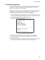
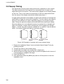
1
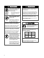
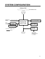
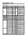
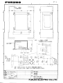
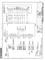
Installation Manual MARINE RADAR MODEL 851 MARK-2 SAFETY INSTRUCTIONS ........................................................................................... i SYSTEM CONFIGURATION ..................................................................................... iii EQUIPMENT LISTS................................................................................................... iv 1. MOUNTING ........................................................................................................ 1-1 1.1 Mounting Methods for Antenna Unit ........................................................................................1-1 1.2 Fixing Holes in Mounting Platform ........................................................................................... 1-2 1.3 Fastening the Radiator to the Radiator Bracket ...................................................................... 1-2 1.4 Mounting the Antenna Unit ...................................................................................................... 1-3 1.5 Connecting the Signal Cable ................................................................................................... 1-7 1.6 Mounting Methods for Display Unit........................................................................................ 1-10 1.7 Mounting the Display Unit...................................................................................................... 1-11 2. WIRING............................................................................................................... 2-1 2.1 Connections ............................................................................................................................. 2-1 2.2 Input/Output Data List.............................................................................................................. 2-3 2.3 Attaching OPTION Connector ................................................................................................. 2-4 2.4 Connection of two NMEA equipments ..................................................................................... 2-6 2.5 Installation Check List.............................................................................................................. 2-7 3. ADJUSTMENTS ................................................................................................. 3-1 3.1 Checking magnetron heater voltage........................................................................................3-1 3.2 Initial Adjustment of Picture ..................................................................................................... 3-2 3.3 Displaying the Installation Menus ............................................................................................ 3-3 3.4 Entering Initial Settings ............................................................................................................ 3-4 3.5 Heading Alignment .................................................................................................................. ..... 3-5 3.6 Sweep Timing .......................................................................................................................... 3-6 PACKING LIST ....................................................................................................... A-1 OUTLINE DRAWINGS............................................................................................ D-1 INTERCONNECTION DIAGRAM .......................................................................... S-1 SCHEMATIC DIAGRAMS........................................................................................S-2 C Yo u r L o c a l A g e n t / D e a l e r 9-52, Ashihara-cho, Nishinomiya, Japan Te l e p h o n e : Te l e f a x : 0 7 9 8 - 6 5 - 2 111 0798-65-4200 All rights reserved. Printed in Japan PUB. No. IME-34900-D (YOSH) MODEL 851 MARK-2 FIRST EDITION D : : JUL. 2000 S E P. 4 , 2 0 0 1 SAFETY INSTRUCTIONS WARNING Radio Frequency Radiation Hazard The radar antenna emits electromagnetic radio frequency (RF) energy which can be harmful, particularly to your eyes. Never look directly into the antenna aperture from a close distance while the radar is in operation or expose yourself to the transmitting antenna at a close distance. Distances at which RF radiation levels of 100 and 10 W/m2 exist are given in the table below. Note: If the antenna unit is installed at a close distance in front of the wheel house, your administration may require halt of transmission within a certain sector of antenna revolution. This is possible Ask your FURUNO representative or dealer to provide this feature. Type Radiator type MODEL 851 MARK-2 XN10A Distance to 100 W/m point 2 0.2 m Distance to 10 W/m point 2 Worst case 3.0 m i WARNING Do not open the equipment unless totally familiar with electrical circuits and service manual. ELECTRICAL SHOCK HAZARD Only qualified personnel should work inside the equipment. Wear a safety belt and hard hat when working on the antenna unit. WARNING Be sure that the power supply is compatible with the voltage rating of the equipment. Connection of an incorrect power supply can cause fire or equipment damage. The voltage rating of the equipment appears on the label above the power connector. Use only the specified power cable. Fire or equipment damage can result if a different cable is used. Serious injury or death can result if someone falls from the radar antenna mast. Construct a suitable service platform from which to install the antenna unit. Serious injury or death can result if someone falls from the radar antenna mast. Turn off the power at the mains switchboard before beginning the installation. Fire, electrical shock or serious injury can result if the power is left on or is applied while the equipment is being installed. Turn off the radar power switch before servicing the antenna unit. Post a warning sign near the switch indicating it should not be turned on while the antenna unit is being serviced. Prevent the potential risk of someone begin struck by the rotating antenna and exposure to RF radiation hazard. ii CAUTION Ground the equipment to prevent electrical shock and mutual interference. Observe the following compass safe distances to prevent deviation of a magnetic compass: Display unit Antenna unit Standard compass Steering compas 0.70 m 0.50 m 1.00 m 0.75 m Use the proper fuse. Use of a wrong fuse can result in fire or permanent equipment damage. SYSTEM CONFIGURATION Antenna Unit XN10A-RSB-0070-065 Navigation device IEC 61162* (In/Out) Remote Display FMD-811 Display Unit Gyrocompass Gyro Converter AD-100 RDP-117-5-M2 External Alarm Buzzer OP03-169 Intergrated Heading Sensor PG-1000 Rectifier RU-3423 *Equivalent to NMEA 0183 Option Ship's mains 12-24 VDC Ship's mains 100/110/115/ 200/220/230 VAC 1φ, 50/60Hz iii EQUIPMENT LISTS Standard Supply Name Type Code No. Qty Antenna Unit XN10A-RSB-0070-065 - 1 Display Unit RDP-117-5-M2 - 1 Remarks CP03-21500 000-087-747 CP03-18401, power cable, 10 m signal cable CP03-21510 000-087-748 CP03-18401, power cable, 15 m signal cable CP03-21520 000-087-749 Select CP03-18401, power cable, one 20 m signal cable CP03-21530 000-087-750 CP03-18401, power cable, 30 m signal cable CP03-21540 000-086-548 CP03-18401, power cable, w/o signal cable Accessories FP03-05900 008-462-050 1 set Spare Parts SP03-12100 000-086-964 1 set Installation Materials Optional Supply Name Type External Buzzer OP03-169 Rectifier RU-3423 Code No. Qty 1 - 1 FM-C6FPS001-050 000-142-031 1 For AD-100/NAV, 5 m w/6P connector at one side FM-C6FPS001-100 000-142-030 1 For AD-100/NAV, 10 m w/6P connector at one side FM-C6FPD001-050 000-143-897 1 For PG-1000/NAV, 5 m w/6P connector at both ends, Straight FM-C6FPD001-100 000-143-898 1 For PG-1000/NAV, 10 m w/6P connector at both ends, Straight FM-C6FPD002-050 000-143-895 1 For NAV, 5 m w/6P connector at both ends, Cross FM-C6FPD002-100 000-143-896 1 For NAV, 10 m w/6P connector at both ends, Cross OP03-170-5 008-466-600 1 For E/S/ NAV, 5m w/6P connector at one side, OP03-172 OP03-170-10 008-466-610 1 For E/S/ NAV, 10m w/6P connector at one side, OP03-172 OP03-171-5 008-466-620 1 For E/S/ NAV, 5m w/6P connector at both ends, OP03-172 OP03-171-10 008-466-630 1 For E/S/ NAV, 10m w/6P connector at both ends, OP03-172 - 1 LCD type Cable Assy. Cable set Remote Display iv Remarks FMD-811 1. MOUNTING 1.1 Mounting Methods for Antenna Unit • The antenna unit is generally installed either on top of the wheelhouse or on the radar mast on a suitable platform. Locate the antenna unit where there is a good all-round view. Any obstruction will cause shadow and blind sectors. A mast for instance, with a diameter considerably less than the width of the radiator, will cause only a small blind sector, but a horizontal spreader or crosstrees in the same horizontal plane as the antenna unit would be a much more serious obstruction; you would need to place the antenna unit well above or below it. • It is rarely possible to place the antenna unit where a completely clear view in all directions is available. Thus, you should determine the angular width and relative bearing of any shadow sectors for their influence on the radar at the first opportunity after fitting. • If you have a radio direction finder on your boat, locate its antenna clear of the antenna unit to prevent interference to the direction finder. A separation of more than two meters is recommended. • To lessen the chance of picking up electrical interference, avoid where possible routing the signal cable near other onboard electrical equipment. Also avoid running the cable in parallel with power cables. • A magnetic compass will be affected if placed too close to the antenna unit. Observe the following compass safe distances to prevent deviation of a magnetic compass: Standard compass, 1.00 m, Steering compass, 0.75 m. • Do not paint the radiator aperture, to ensure proper emission of the radar waves. • When this radar is to be installed on larger vessels, consider the following points: ! The signal cable run between the antenna and the display comes in lengths of 10 m (standard), 15 m, 20 m and 30 m. Whatever length is used it must be unbroken; namely, no splicing allowed. ! Deposits and fumes from a funnel or other exhaust vent can adversely affect the aerial performance and hot gases may distort the radiator portion. The antenna unit must not be mounted where the temperature is more than 70°C. 1-1 1. MOUNTING As shown in the figure below, the antenna unit may be installed on the bridge, on a common mast or on the radar mast. (a) On bridge (b) Common mast (c) Radar mast Figure 1-1 Antenna unit mounting methods 1.2 Fixing Holes in Mounting Platform Referring to the outline drawing on page D-1, drill five holes in the mounting platform: four holes of 15 mm diameter for fixing the antenna unit and one hole of 25-30 mm diameter for the signal cable. 1.3 Fastening the Radiator to the Radiator Bracket There are installation materials for the Radiator not shown in the packing list. These are as shown below. Name O-ring Hex. head bolt Flat washer Qty 1 4 4 Remarks NBR M8 x 30 M8 Spring washer 4 M8 Silicone sealant 1 #1211, 50g 1. Remove the radiator cap from the radiator bracket. 2. Coat contacting surface between antenna radiator and radiator bracket with silicone sealant as shown in Figure 1-2. Coat hatched area with silicone sealant. Groove Radiator Figure 1-2 Coating the bottom of antenna radiator for XN10A with silicone sealant 1-2 1. MOUNTING 3. 4. 5. 6. Coat threaded holes on the antenna radiator with silicone sealant. Grease the O-ring and set it to the radiator bracket. Lay the antenna radiator on the radiator bracket. Coat the radiator fixing bolts (4 pcs.) with silicone sealant. Fasten the antenna radiator to the radiator bracket with the radiator fixing bolts, flat washers and spring washers. Antenna radiator O-ring Radiator bracket Flat washer Spring washer Hex head bolt (M8 x 30) Coat threaded holes with silicone sealant. Coat bolts with silicone sealant. Figure 1-3 Fastening the radiator bracket to the antenna unit chassis 1.4 Mounting the Antenna Unit The antenna unit can be mounted using the fixing holes on the outside (200 x 200 mm) or inside (140 x 150 mm) the antenna unit. Outside fixing holes Use the hex head bolt (supplied) to mount the antenna unit as below. 1. Lay the corrosion-proof rubber mat (supplied) on the mounting platform. Ground terminal Rubber mat Bow mark Figure 1-4 Location of rubber mat 1-3 1. MOUNTING 2. Lay the antenna unit on the mounting platform, orienting it as shown in Figure 1-5. BOW STERN Figure 1-5 Antenna unit CAUTION Do not lift the antenna unit by the radiator; lift it by the housing. The radiator may be damaged. 3. Insert four hex bolts and seal washers from the top of the antenna housing. Insert the seal washers with the larger diameter next to the bolt heads. Be sure the seal washer, not other washers, is next to bolt head. Hex bolt Seal washer Flat washer Spring washer Nut Figure 1-6 Fixing the antenna unit chassis 1-4 1. MOUNTING 4. Pass flat washers, spring washers and nuts onto hex bolts. Fasten by tightening nuts. Do not fasten by tightening the hex bolts; seal washers may be damaged. Seal washer Antenna unit Mounting platform Silicone sealant Rubber mat Flat washer Figure 1-7 How to fasten antenna unit to mounting platform 5. Coat flat washers, spring washers, nuts and exposed parts of bolts with silicone sealant. 6. Prepare ground point in mounting platform (within 300 mm of ground terminal on antenna unit) using M6 x 25 bolt, nut and flat washer. 7. Run the ground wire (RW-4747, 340 mm) between the ground terminal and ground point. 8. Coat ground terminal and ground point with silicone sealant as shown in Figure 1-8. Hex bolt Flat washer Ground terminal Silicone sealant Ground wire OR Flat washer Spring washer Hex nut GROUND POINT Hex nut Spring washer Flat washer Hex nut Weld here. GROUND TERMINAL Silicone sealant Ground wire Antenna unit Figure 1-8 How to coat ground point and ground terminal with silicone sealant 1-5 1. MOUNTING Fixing holes inside antenna unit This method requires removal of the RF unit in the antenna unit to access inside fixing holes. Use hex head bolts, flat washers, spring washers and nuts (local supply) to mount the antenna unit, confirming length of bolts. 1. Loose four hex. bolts to open the antenna unit. Refer to Figure 1-10 for location. Hex head bolt M8X25 2pcs. Upper chassis RFunit Hex head bolt M10X20 4pcs. Spring Washer M10 4 pcs. Cover Pan head screw M3X8 4pcs. Square bushing Lower chassis Figure 1-9 Antenna unit chassis, upper chassis separated 2. 3. 4. 5. 6. 7. 8. Unplug connector connected between upper and lower chassis. Separate upper chassis from lower chassis by removing two hex head bolts. Remove cover by unfastening four pan head screws. Remove connector from RF unit. Remove RF unit by unfastening four hex head bolts. Lay the corrosion-proof rubber mat (supplied) on the mounting platform. Fasten the lower chassis to the mounting platform with hex head bolts, spring washers, flat washers and nuts (local supply), and then coat flat washers, nuts and exposed parts of bolts with silicone sealant. Cut a slit in rubber bushing and insert bolt into bushing. Do not use seal washers. 9. Reassemble RF unit, cover and upper chassis. 10. Set four caps (supplied) into outside fixing holes. 11. Do steps 6-8 in “Outside fixing holes”. 1-6 1. MOUNTING 1.5 Connecting the Signal Cable Only one signal cable runs from the display unit to the antenna unit. In order to minimize the chance of picking up electrical interference, avoid where possible routing the signal cable near other onboard electrical equipment. Also, avoid running the cable in parallel with power cables. Pass the cable through the hole and apply sealing compound around the hole for waterproofing. 1. Open the antenna cover by loosening four hex. bolts, and then fix the stay. Stay Cable gland Hex. bolt Figure 1-10 Antenna unit chassis, cover opened 2. Unfasten the cable gland assembly (plate, gasket, flat washer). 3. Pass the signal cable w/connector through the bottom of the antenna unit chassis. Pass the cable through the gland assembly as shown below. Bolt 4-M4X16 Plate Gasket Crimp-on lug Flat washer Figure 1-11 Passing the signal cable through the cable gland assembly 4. Fasten the crimp-on lug on the shield to one of the fixing bolts of the cable gland assembly. 1-7 1. MOUNTING 5. Position the signal cable so that no more than 4 cm of the sheath is exposed as shown in the figure below. Tighten fixing bolts. Tubing Shield Sheath Bolt Within 4 cm Plate Gasket Flat washer CABLE GLAND Figure 1-12 How to fix signal cable in cable gland 6. Unfasten four screws shown in the figure below. Four screws Figure 1-13 Antenna unit chassis, cover opened 7. Pass the signal cable through the cable protector. Cable protector Figure 1-14 Antenna unit chassis, cover opened 8. Connect the signal cable to the RTB Board (03P9249), referring to the interconnection diagram and the figure below. 1-8 1. MOUNTING 9. Attach three EMI cores to the signal cable as shown below. J821 VH9P J822 VH2P J824 NH13P Lead in cable here. EMI core RFC-13 J823 VH4P Clamp Route cable along here. Figure 1-15 Antenna unit chassis, cover opened 10.Fix the signal cable with the cable clamp. 11. Release the stay and close the cover. Loosely fasten the cover fixing screws; you will have to make some adjustments inside after completion of wiring. Note: When closing the cover, set the gaskets to grooves in the bottom chassis, then tighten bolts. BOTTOM CHASSIS GROOVE GASKET SCANNER BOLT Torque :9.8 ± 0.1 N • m Figure 1-16 1-9 1. MOUNTING 1.6 Mounting Methods for Display Unit When selecting a mounting location for the display unit keep in mind the following points. • The display unit is designed and constructed to be splashproof, thus it can be installed outdoors. You can even hose it down after a day’s outing. If it is to be installed outdoors, we recommend installing it an enclosed cabinet, for maximum protection against the marine environment. • The temperature and humidity of the mounting location should be stable and moderate. No LCD can provide adequate contrast if the ambient temperature is too extreme. • The display unit consumes only a moderate amount of power, so there is no need for forced air ventilation. However, you should provide adequate space behind and around the unit to permit circulation of air and to provide convenient access to the rear connectors. • Even though the picture is quite legible even in bright sunlight, keep the display unit out of direct sunlight or at least shaded because of heat that can build up inside the cabinet. • Locate the display unit in a position where you can view and operate it conveniently but where there is no danger of salt or fresh water spray or immersion. • The orientation of the display unit should be so the radar screen is viewed while the operator is facing in the direction of the bow. This makes determination of your position much easier. • Make sure you allow enough clearance both to get to the connectors behind the unit and to allow you to get your hands in on both sides to loosen or tighten the mounting knobs. Make sure you leave at least a foot or so of “service loop” of cables behind the unit so it can be pulled forward for servicing or easy removal of the connectors. • A magnetic compass will be affected if placed too close to the display unit. Observe the minimum compass safe distances to prevent deviation of a magnetic compass: standard compass, 0.7 meters, and steering compass, 0.5 meters. 1-10 1. MOUNTING 1.7 Mounting the Display Unit The display unit is designed to be mounted on a tabletop. 1. Using the hanger as a template, mark screw locations in the mounting location. 2. Fix the hanger to the mounting location with four 5 x 20 tapping screws (supplied). 3. Fit the knob bolts to the display unit. 4. Install the display unit in the hanger. 5. Tighten the knob bolts securely. 236(9.3") 222(8.7") Cutout dimensions for flushmount ** 4 - ∅6 FIXING HOLES ** 268 (10.55") 130 (5.12") *80 (3.15") 15 (0.59") *140 (5.51") 238 (9.37") 10 100 (0.39") (3.94") * : SERVICING CLEARANCE 15 20 **: If the mounting location is (0.59") *80 (0.79") subject to heavy vibration, (3.15") fasten the display unit in the hanger perpendicularly so that it contacts the rubber cushions. Figure 1-17 How to mount the display unit 1-11 2. WIRING 2.1 Connections Connect the signal and power cables, the ground wire and optional equipment as shown in Figure 2-1. Signal cable S03-83 Power cable connector Connect power cable here. OPTION CAUTION For 24 volt power, replace fuse with 5A fuse (supplied), and attach "5A fuse label" to the fuse cover on power cable. Factory setting is 10A for 12 VDC set. Signal cable connector Connect signal cable from antenna here. HDG NMEA OPTION connector *1 Connect remote display here. HDG connector *2 Connect heading sensor here. NMEA connector *3 Connect navaid here. 10.2-31.2VDC 1 3 GND 2 OPTION DJ-1 MARINE RADAR TYPE SER.NO. DATE COMPASS SAFE DISTANCE STD M STEER M EQUPMENT CLASS FURUNO ELECTRIC CO., LTD OPTION connector Connect navaid, echo sounder or external buzzer here. CAUTION Tighten the boot-band securely to ensure watertightness. Ground terminal Connect ground wire between here and ship's ground. See next page. Figure 2-1 Display unit, rear view *1:The following cables are supplied with remote display. Remarks Type Code no. FM-C10FPD002-050 000-143-894 5m FM-C10FPD002-100 000-143-893 10m FM-C10FPD002-150 000-143-892 15m 2-1 2. WIRING FM-C10FPD002-200 000-143-891 20m FM-C10FPD002-300 000-143-890 30m *2:The following cables are optionally supplied for heading sensor connection. Remarks Type Code no. FM-C6FPD001-050 000-143-897 PG-1000 (5m) FM-C6FPD001-100 000-143-898 PG-1000 (10m) *3:The following cables can be used for NMEA 0183 format connection. Remarks Type Code no. FM-C6FPD002-050 000-143-895 6P-6P(5m), Cross type FM-C6FPD002-100 000-143-896 6P-6P(10m) , Cross type Signal cable connection 1. Connect the signal cable to DJ-1 on the rear panel of the display unit. Rubber cover Boot-band DJ Connector Cable DJ-1 Display unit Figure 2-2 2. Cover the connector with the rubber cover. The projection on the connector base is inserted into the groove on the rubber cover. Rubber cover Grasp Grasp Groove Display unit Figure 2-3 3. Put the boot-band as shown below, and tighten it. Boot-band Display Unit Figure 2-4 2-2 2. WIRING 2.2 Input/Output Data List This radar can receive the following NMEA 0183 format data sentences from a navigator or echosounder. Your vessel’s position in latitude and longitude, the range and bearing to waypoint, speed, course, and depth may be seen on the display. Input GLL: BWR: BWC: GLC: GTD: RMA: RMB: RMC: VTG: MTW: DBT: DBS: DPT: GGA: VBW: DBK: HDM: HDG: HDT: Geographic position – Lat/Long Bearing and Distance to Waypoint – Rhumb line Bearing and Distance to Waypoint – Great circle Geographic position – Loran-C Geographic position – Time Difference Recommended Minimum Specific Loran-C Data Recommended Minimum Navigation Information Recommended Minimum Specific GPS/Transit Data Track Made Good and Ground Speed Water Temperature Depth Below Transducer (Ver 1.5) Depth Below Surface Depth (Ver 2.0) GPS – Rx status, L/L Dual ground/water speed Depth Heading Magnet Heading Deviation and Variation Heading True TLL: RSD: Target Position Radar System Data Output 2-3 2. WIRING 2.3 Attaching OPTION Connector You can connect external buzzer or NMEA equipment (Echosounder and/or Video plotter) by attaching the optional connector kit. This radar can output NAV data received from a navaid to a video plotter. For how to distribute NAV data, refer to “2.4 Connection of two equipments”. NMEA Navaid TLL, RSD MODEL 851 MARK-2 OPTION J61 Video plotter Figure 2-5 1. 2. 3. 4. Remove the plastic cover of OPTION from rear cover. Disconnect all connectors from rear panel. Dismount the display unit from hanger. Unfasten eight screws and three nuts fixing the waterproof connector to remove the rear covers. Waterproof Connector assy. Multipin connector J61 NMEA J59 EXT BUZZ Figure 2-6 Display unit rear view 5. Connect connector assy. to J61(NMEA)/J59(EXT BUZZ) on SPU Board (SPU-9180). To distribute NAV data, modify waterproof connector assy. as shown figure 2-7. 2-4 2. WIRING Waterproof Connector assy. 1 XH3P 2 3 BRN BRN 1 2 ORG XH5P 3 4 YEL 5 RED RED 1 ORG XH5P 2 3 4 YEL 5 1. Remove #1 and #3 contacts from the XH3P. 2. Discard XH3P connector. 3. Insert brown and red wires (contacts) into the XH5P as shown above. 4. Connect XH5P connector to J61 on SPU Board. Figure 2-7 6. Pass waterproof connector through the hole named OPTION on rear cover. 7. Reassemble the display unit. CAUTION When reassembling the display unit, be sure the rear cover is fitted to the front chassis properly when closing the rear cover. Press the center of the rear cover to plug in the multipin connector on the rear cover. 8. Tighten the nut of the connector (Torque: 7.6±0.02N⋅m). 9. Mount the display unit in the hanger. 10. Connect all connectors on rear panel. 2.4 Connection of two NMEA equipments You can connect a video plotter and echosounder to the 6P OPTION connector. 1. Wire OP03-170-5/OP03-170-10 as shown in Figure 2-8. 2. Pass steel mesh through the cable. 3. Solder cable. 2-5 2. WIRING Shield Solder Other Equipment (Echosounder data not output.) 1 2 3 4 5 SHIELD 6 RD_H RD_C TD-H TD-C RD-H RD-C MODEL 851 MARK-2 OPTION connector SHIELD Echosounder 10mm 10mm 10mm 10mm TD_H TD_C SHIELD FM-C6FPS001 Figure 2-8 4. Cover shield with steel mesh by cable ties. Shield Cable tie Steel mesh Other Equipment MODEL851 MARK2 OPTION connector Echosounder After tieing, wrap with self-vulcanizing tape. Figure 2-9 5. Wrap with self-vulcanizing tape. 2.5 Installation Check List After completing the installation it is a good idea to check for proper installation. Follow the checklist below and tick boxes to show proper completion. 2-6 ! Is the signal cable secured against a mast or bulkhead? ! Is the cable gland or cable entry on the deck fully waterproofed? ! Are the connections to the battery correct polarity? ! Are all the antenna and display units grounded? ! Are all connectors at the rear of the display unit fastened securely? 3. ADJUSTMENT 3.1 Checking magnetron heater voltage Magnetron heater voltage is formed on the MD Board (03P9235) of the antenna unit, and is preadjusted at the factory for use with any length of signal cable. Therefore no adjustment is required. However, check magnetron heater voltage as follows: 1. Turn on the radar and leave it in stand-by. 2. Open the antenna cover. 3. Unfasten four screws to remove the RF section cover. DANGER ELECTRICAL SHOCK HAZARD This check is done with the power on DO NOT touch the magnetron. Magnetron Four screws Figure 3-1 Antenna unit, cover opened 4. Connect a multimeter, set to 10 VDC range, between test point J825#4 and J825#6 (GND) on the RTB Board (03P9249). Measure voltage at this connector (J825). Figure 3-2 Antenna unit, cover opened 5. Confirm the meter reads 7.6 V ±0.1 V. 6. Close the antenna cover and tighten the cover fixing screws. 3-1 3. ADJUSTMENT 3.2 Initial Adjustment of Picture Follow the procedure below to obtain proper radar picture. 1. Press the [POWER] key on the display unit. The display should light. Wait until the message "ST-BY" appears on the screen. (About one and half minutes.) 2. Press [ST-BY/TX] key to transmit. The radar will start transmitting, and you will probably see some targets around you, even though the radar is not yet properly adjusted. 3. Select a long range. 4. Press the [ECHO] key. The following display appears. Select auto (or manual) by pressing omnipad followed by [ENT] key. GAIN ◆ [ STC ◆ [ AUTO 1 2 3 MAN Item selected for adjustment AUTO 1 2 3 MAN A.C Select item/option by pressing appropriate omnipad arrow. RAIN FTC 1 00 01 2 Select auto (or manual) by pressing omnipad followed by [ENT] key. Current level ECHO KEY TO EXIT Figure 3-3 Display for adjustment of gain, STC, A/C RAIN and FTC 5. Press the omnipad to select GAIN-AUTO, if it is not already selected. 6. Select minimum range. Press the [ECHO] key and press the omnipad to select STC-AUTO, if it is not already selected. 3-2 3. ADJUSTMENT 3.3 Displaying the Installation Menus Two sets of installation menus, Installation Setup 1 and Installation Setup 2 enable entry of initial settings and adjustment of the radar. Procedure 1. Turn on the power while pressing and holding down the [HM OFF] key. 2. Press the [MENU] key. ● MAIN MENU ● Select item by ▲▼ keys and press ENT key. 1. Backlight/Brilliance 2. P/L, IR, NR & Radar Mode 3. Nav Data 4. Mode & Function 5. Tuning AUTO MANUAL 6. Self Check 7. Installation Setup 1 ................. Press HM-OFF to temporarily hide menu. <Press MENU key to escape.> Figure 3-4 main menu 3. Press the omnipad to select Installation Setup 1 and press the [ENT] key. ● INSTALLATION SETUP 1 ● Select item and option by ▲▼ keys. 1. Key Beep OFF ON 2. Hdg Sensor MAG GYRO 3. Ant on Tx ROTATE STOP 4. Demo Display OFF ON 5. Rotation Speed 24 48 rpm 6. Installation Setup 2 .Press . .HM-OFF . . . to. temporarily .......... hide menu. <Press MENU for main menu.> Figure 3-5 Installation setup menu 1 4. To display the Installation Setup 2 menu, press the omnipad to select Installation Setup 2 and press the [ENT] key. 3-3 3. ADJUSTMENT ● INSTALLATION SETUP 2 ● Select item and option by trackball. 1. Align Heading 2. Adjust Sweep Timing 3. On Hours 0000019.8 H 4. Tx Hours 0000016.0 H ................. Press HM-OFF to temporarily hide menu. <Press MENU for main menu.> Figure 3-6 Installation setup 2 menu 3.4 Entering Initial Settings 1. At the Installation Setup 1 menu, press the omnipad to select Key Beep. (Key Beep turns on or off the buzzer which sounds when a key is pressed.) 2. Press the omnipad to select OFF or ON. 3. Select Hdg Sensor. 4. Select type of heading sensor connected to the radar; MAGnetic compass or GYROcompass. 5. Press the [ENT] key. Leave the menu open to complete the next several adjustments. 3-4 3. ADJUSTMENT 3.5 Heading Alignment You have mounted the antenna unit facing straight ahead in the direction of the bow. Therefore, a small but conspicuous target dead ahead visually should appear on the heading mark (zero degrees). In practice, you will probably observe some small error on the display because of the difficulty in achieving accurate initial positioning of the antenna unit. The following adjustment will compensate for this error, 360 degrees. 1. Identify a suitable target (for example, ship or buoy) at a range between 1/8 to 1/4 miles, preferably near the heading mark. To minimize error, keep echoes in the outer half of the picture by changing the range. 2. Display the Installation Setup 2 menu. ● INSTALLATION SETUP 2 ● Select item and option by trackball. 1. Align Heading 2. Adjust Sweep Timing 3. On Hours 0000019.8 H 4. Tx Hours 0000016.0 H ................. Press HM-OFF to temporarily hide menu. <Press MENU for main menu.> Figure 3-7 Installation setup 2 menu 3. 4. 5. 6. Select Align Heading by pressing omnipad and press the [ENT] key. Press the omnipad to bisect the target selected at step 2 with the EBL. Press the [ENT] key, As a final test, move the boat towards a small buoy and confirm that the buoy shows up dead ahead on the radar when it is visually dead ahead. 3-5 3. ADJUSTMENT 3.6 Sweep Timing This adjustment ensures proper radar performance, especially on short ranges. The radar measures the time required for a transmitted echo to travel to the target and return to the source. The received echo appears on the display based on this time. Thus, at the instant the transmitter is fired, the sweep should start from the center of the display (sometimes called sweep origin.) A trigger pulse generated in the display unit goes to the antenna unit through the signal cable to trigger the transmitter (magnetron). The time taken by the signal to travel up to the antenna unit varies, depending largely on the length of signal cable. During this period the display unit should wait before starting the sweep. When the display unit is not adjusted correctly, the echoes from a straight local object (for example, a harbor wall or straight pier) will not appear with straight edges namely, they will be seen as “pushed out” or “pulled in” near the picture center. The range of objects will also be incorrectly shown. (1) Correct (2) Target pushed (3) Target pushed inward outward Figure 3-8 Examples of improper and correct sweep timings 1. Display the Installation Setup 2 menu and select Adjust Sweep Timing by pressing omnipad. 2. Transmit the radar on the shortest range. 3. Visually select a straight echo (harbor wall, straight pier). 4. While looking at the target selected above, press omnipad at the 9 o’clock or 3 o’clock position to straighten the target. 5. Press the [ENT] key. 6. After adjustment press the [MENU] key and turn off the power to close the installation menu. 3-6