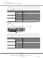
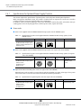
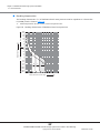
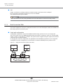
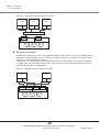
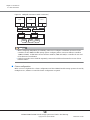
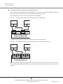
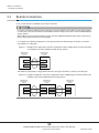
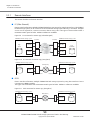
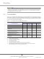
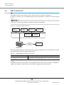
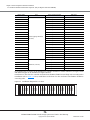
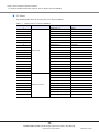
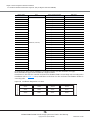
1
P3AM-4822-12ENZ0
ETERNUS DX80 S2/DX90 S2
Disk storage system
User's Guide -Site Planning-
This page is intentionally left blank.
Preface
Fujitsu would like to thank you for purchasing our ETERNUS DX80 S2/DX90 S2 Disk storage system.
The ETERNUS DX80 S2/DX90 S2 Disk storage system is designed to be connected to Fujitsu (PRIMEQUEST or
PRIMERGY) or non-Fujitsu servers.
This manual describes the environmental requirements that are necessary to install and use the ETERNUS
DX80 S2/DX90 S2 Disk storage system.
This manual is intended for use of ETERNUS DX80 S2/DX90 S2 Disk storage system in regions other than Japan.
Please carefully review the information outlined in this manual.
Twelfth Edition
June 2013
Microsoft, Windows, Windows Server, and Internet Explorer are either registered trademarks or trademarks of
Microsoft Corporation in the United States and/or other countries.
Mozilla, Firefox, and the Mozilla and Firefox logos are trademarks or registered trademarks of the Mozilla
Foundation in the United States and other countries.
The company names, product names and service names mentioned in this document are registered
trademarks or trademarks of their respective companies.
3
ETERNUS DX80 S2/DX90 S2 Disk storage system User’s Guide -Site PlanningCopyright 2013 FUJITSU LIMITED
P3AM-4822-12ENZ0
About this Manual
Organization
This manual is composed of the following four chapters:
● Chapter 1 Hardware Configurations
This chapter describes the main components and the relative optional products that are installed in the
ETERNUS DX80 S2/DX90 S2 Disk storage system.
● Chapter 2 ETERNUS DX Disk Storage System Installation
This chapter describes the installation specifications, the installation environment, and the power
requirements.
● Chapter 3 Connections
This chapter describes the configuration for each interface to connect to the ETERNUS DX80 S2/DX90 S2
Disk storage system.
● Chapter 4 Rack and Optional Product Installation
This chapter describes the requirements for rack installation.
This chapter also describes the standard installation rules (installation locations and installation order) of
the optional products before shipment from the factory when the optional products are purchased with the
ETERNUS DX80 S2/DX90 S2 Disk storage system at the same time.
Naming Conventions
■ Abbreviations used in this manual
• "ETERNUS DX Disk storage system" refers to the ETERNUS DX80 S2/DX90 S2 Disk storage system.
• "CA" refers to a host interface module that is used in an ETERNUS DX Disk storage system to connect to a
server.
• "Host Bus Adapter (HBA)" refers to the interface module that is normally used by the server to connect to
ETERNUS DX Disk storage systems.
An "FC card", "LAN card", "Network Interface Card (NIC)", "Converged Network Adapter (CNA)", or "SAS card"
may be used instead, depending on the server and interface.
• Trademark symbols such as ™ and ® are omitted in this document.
4
ETERNUS DX80 S2/DX90 S2 Disk storage system User’s Guide -Site PlanningCopyright 2013 FUJITSU LIMITED
P3AM-4822-12ENZ0
About this Manual
Warning Notations
Warning signs are shown throughout this manual in order to prevent injury to the user and/or material
damage. These signs are composed of a symbol and a message describing the recommended level of caution.
The following explains the symbol, its level of caution, and its meaning as used in this manual.
CAUTION
This symbol indicates the possibility of minor or moderate personal injury, as well
as damage to the ETERNUS DX Disk storage system and/or to other users and their
property, if the ETERNUS DX Disk storage system is not used properly.
How Warnings are Presented in this Manual
A message is written beside the symbol indicating the caution level. This message is marked with a vertical
ribbon in the left margin, to distinguish this warning from ordinary descriptions.
An example is shown here.
Warning Level Indicator
Example Warning
Warning Type Indicator
Warning Details
To avoid damaging the ETERNUS DX Disk storage system,
pay attention to the following points when cleaning the ETERNUS DX
Disk storage system:
- Make sure to disconnect the power when cleaning.
- Be careful that no liquid seeps into the ETERNUS DX Disk storage
system when using cleaners, etc.
- Do not use alcohol or other solvents to clean the ETERNUS DX Disk
storage system.
Warning Layout Ribbon
5
ETERNUS DX80 S2/DX90 S2 Disk storage system User’s Guide -Site PlanningCopyright 2013 FUJITSU LIMITED
P3AM-4822-12ENZ0
Table of Contents
Chapter 1
1.1
1.1.1
1.1.2
1.2
1.2.1
1.2.2
Hardware Configurations
11
Controller Enclosure .......................................................................................................... 11
Controllers ..................................................................................................................................................... 15
Power Supply Units ........................................................................................................................................ 17
Drive Enclosures ................................................................................................................ 18
I/O Modules ................................................................................................................................................... 21
Power Supply Units ........................................................................................................................................ 22
1.3
Enclosure Connection Path ............................................................................................... 22
1.4
Drives ................................................................................................................................ 23
1.4.1
1.4.2
1.5
2.5" Drives ..................................................................................................................................................... 23
3.5" Drives ..................................................................................................................................................... 24
Power Distribution Units (Only for Regions Other than EMEA&I) ...................................... 24
Chapter 2
2.1
2.1.1
2.1.2
2.2
2.2.1
2.2.2
ETERNUS DX Disk Storage System Installation
27
Installation Specifications ................................................................................................. 27
ETERNUS DX80 S2 .......................................................................................................................................... 27
ETERNUS DX90 S2 .......................................................................................................................................... 29
Storage System Dimensions .............................................................................................. 31
Controller Enclosure Dimensions ................................................................................................................... 31
Drive Enclosure Dimensions .......................................................................................................................... 33
2.3
Package Size ..................................................................................................................... 35
2.4
Installation Area ............................................................................................................... 36
2.5
Installation Environment .................................................................................................. 36
2.5.1
2.5.2
2.5.3
2.6
2.6.1
2.6.2
2.7
Air Conditioning ............................................................................................................................................. 36
Earthquake Resistance .................................................................................................................................. 37
Load Bearing Capacity for Floors .................................................................................................................... 37
Outlet/Socket Specifications .............................................................................................. 37
Specifications for Optional Power Supply Products ......................................................................................... 38
Required Number of Outlets/Sockets ............................................................................................................. 40
Circuit Protectors ............................................................................................................... 41
6
ETERNUS DX80 S2/DX90 S2 Disk storage system User’s Guide -Site PlanningCopyright 2013 FUJITSU LIMITED
P3AM-4822-12ENZ0
Table of Contents
Chapter 3
3.1
3.1.1
3.1.2
3.2
3.2.1
3.2.2
Connections
46
Host Connections .............................................................................................................. 46
Host Interfaces .............................................................................................................................................. 46
Host Connection Path .................................................................................................................................... 48
Remote Connections ......................................................................................................... 52
Remote Interfaces ......................................................................................................................................... 53
Connectable Models ...................................................................................................................................... 54
3.3
LAN Connection ................................................................................................................ 55
3.4
Power Supply Connection .................................................................................................. 56
3.4.1
3.4.2
3.5
Input Power Supply Lines ............................................................................................................................... 57
UPS Connection ............................................................................................................................................. 59
Power Synchronized Connections ...................................................................................... 60
Chapter 4
4.1
4.1.1
4.1.2
4.2
4.2.1
4.2.2
4.3
4.3.1
4.3.2
4.3.3
4.3.4
Rack and Optional Product Installation
64
Rack Installation Requirements ........................................................................................ 64
Placement in the Rack ................................................................................................................................... 64
Cable Connection ........................................................................................................................................... 65
Installable Racks ............................................................................................................... 67
Fujitsu Racks .................................................................................................................................................. 67
Non-Fujitsu Racks .......................................................................................................................................... 68
Standard Installation Rules Before Shipment (Only for Regions Other than EMEA&I) ....... 69
Host Interfaces .............................................................................................................................................. 70
Drive Enclosures ............................................................................................................................................ 71
Drives ............................................................................................................................................................ 72
Drive Installation Examples ........................................................................................................................... 77
7
ETERNUS DX80 S2/DX90 S2 Disk storage system User’s Guide -Site PlanningCopyright 2013 FUJITSU LIMITED
P3AM-4822-12ENZ0
List of Figures
Figure 1.1
Figure 1.2
Figure 1.3
Figure 1.4
Figure 1.5
Figure 1.6
Figure 1.7
Figure 1.8
Figure 1.9
Figure 1.10
Figure 1.11
Figure 1.12
Figure 1.13
Figure 1.14
Figure 1.15
Figure 1.16
Figure 1.17
Figure 1.18
Figure 1.19
Figure 1.20
Figure 1.21
Figure 1.22
Figure 1.23
Figure 1.24
Figure 1.25
Figure 2.1
Figure 2.2
Figure 2.3
Figure 2.4
Figure 2.5
Figure 2.6
Figure 2.7
Figure 2.8
Figure 2.9
Figure 2.10
Figure 2.11
Figure 3.1
Figure 3.2
Figure 3.3
Figure 3.4
Figure 3.5
Figure 3.6
Figure 3.7
Figure 3.8
Figure 3.9
Figure 3.10
Front view of a 2.5" type controller enclosure..............................................................................................
Rear view of a 2.5" type controller enclosure (single-controller type)..........................................................
Rear view of a 2.5" type controller enclosure (dual-controller type) ............................................................
Top view of a 2.5" type controller enclosure ................................................................................................
Side view of a 2.5" type controller enclosure ...............................................................................................
Front view of a 3.5" type controller enclosure..............................................................................................
Rear view of a 3.5" type controller enclosure (single-controller type)..........................................................
Rear view of a 3.5" type controller enclosure (dual-controller type) ............................................................
Top view of a 3.5" type controller enclosure ................................................................................................
Side view of a 3.5" type controller enclosure ...............................................................................................
Front view of a 2.5" type drive enclosure .....................................................................................................
Rear view of a drive enclosure (single-IOM type) ........................................................................................
Rear view of a drive enclosure (dual-IOM type) ...........................................................................................
Top view of a 2.5" type drive enclosure........................................................................................................
Side view of a 2.5" type drive enclosure.......................................................................................................
Front view of a 3.5" type drive enclosure .....................................................................................................
Rear view of a drive enclosure (single-IOM type) ........................................................................................
Rear view of a drive enclosure (dual-IOM type) ...........................................................................................
Top view of a 3.5" type drive enclosure........................................................................................................
Side view of a 3.5" type drive enclosure.......................................................................................................
Enclosure connection path (dual-controller type) .......................................................................................
Enclosure connection path (single-controller type) .....................................................................................
Power distribution unit (AC200-240V, 1U, Max 2 enclosures connection) ...................................................
Power distribution unit (AC200-240V, 2U, Max 6 enclosures connection) ...................................................
Power distribution unit (AC200-240V, 2U, Max 8 enclosures connection) ...................................................
2.5" type controller enclosure dimensions...................................................................................................
3.5" type controller enclosure dimensions...................................................................................................
2.5" type drive enclosure dimensions ..........................................................................................................
3.5" type drive enclosure dimensions ..........................................................................................................
Installation area and service area ...............................................................................................................
Power distribution unit (1U)........................................................................................................................
Power distribution unit (2U)........................................................................................................................
Breaking characteristics of distribution board circuit protectors ..................................................................
Example of a power supply connection using a power distribution unit (1U)..............................................
Example of a power supply connection using a power distribution unit (2U)..............................................
Example of a power supply connection without power distribution units....................................................
Single path connection (direct connection).................................................................................................
Single path connection (switch connection)................................................................................................
Multipath connection (direct connection) ...................................................................................................
Multipath connection (switch connection) ..................................................................................................
Connection that satisfies the system requirements (for availability)...........................................................
Connection that satisfies the system requirements (for enhanced performance)........................................
Example of non-supported connection configuration (when multiple types of
remote interfaces are installed in the same ETERNUS DX Disk storage system) ..........................................
Example of supported connection configuration (when multiple types of
remote interfaces are installed in the same ETERNUS DX Disk storage system) ..........................................
FC connection for remote copy (redundant path) ........................................................................................
FC connection for remote copy (using lines)................................................................................................
11
12
12
13
13
13
14
14
15
15
18
18
19
19
19
20
20
20
21
21
22
23
24
25
26
31
32
33
34
36
40
41
42
43
44
45
48
49
49
50
51
51
52
52
53
53
8
ETERNUS DX80 S2/DX90 S2 Disk storage system User’s Guide -Site PlanningCopyright 2013 FUJITSU LIMITED
P3AM-4822-12ENZ0
List of Figures
Figure 3.11
Figure 3.12
Figure 3.13
Figure 3.14
Figure 3.15
Figure 3.16
Figure 3.17
Figure 3.18
Figure 3.19
Figure 4.1
Figure 4.2
Figure 4.3
Figure 4.4
Figure 4.5
Figure 4.6
Figure 4.7
Figure 4.8
Figure 4.9
Figure 4.10
iSCSI connection for remote copy (using lines) ............................................................................................
Example of a LAN connection......................................................................................................................
Dual-line power supply when connecting to power sockets.........................................................................
Dual-line power supply when connecting to UPS units................................................................................
Single-line power supply when connecting to power sockets ......................................................................
Single-line power supply when connecting to a UPS unit ............................................................................
Single-line power supply when connecting to a power socket and a UPS unit.............................................
Power control using a power synchronized unit (when connecting one or two servers) ..............................
Power control using a power synchronized unit (when connecting three or more servers) .........................
AC cable connection ....................................................................................................................................
QSFP cable connection (single-controller type) ...........................................................................................
QSFP cable connection (dual-controller type)..............................................................................................
Unit installation area ..................................................................................................................................
Installation diagram for a host interface (single-controller type)................................................................
Installation diagram for host interfaces (dual-controller type)....................................................................
Installation diagram for 2.5" drives .............................................................................................................
Installation diagram for 3.5" drives .............................................................................................................
Drive installation example at shipment (2.5" type controller enclosure).....................................................
Drive installation example at shipment (3.5" type controller enclosure).....................................................
53
55
57
57
57
58
58
61
62
65
66
67
68
70
71
74
76
77
78
9
ETERNUS DX80 S2/DX90 S2 Disk storage system User’s Guide -Site PlanningCopyright 2013 FUJITSU LIMITED
P3AM-4822-12ENZ0
List of Tables
Table 1.1
Table 1.2
Table 1.3
Table 1.4
Table 1.5
Table 1.6
Table 1.7
Table 1.8
Table 1.9
Table 1.10
Table 2.1
Table 2.2
Table 2.3
Table 2.4
Table 2.5
Table 2.6
Table 2.7
Table 2.8
Table 2.9
Table 2.10
Table 2.11
Table 3.1
Table 3.2
Table 3.3
Table 4.1
Table 4.2
Table 4.3
Table 4.4
Table 4.5
Table 4.6
Table 4.7
Host interface specifications........................................................................................................................
Drive interface port specifications for controllers.........................................................................................
LAN port specifications for controllers .........................................................................................................
PWC port specifications ...............................................................................................................................
Drive interface port specifications for I/O modules ......................................................................................
2.5" drive specifications...............................................................................................................................
3.5" drive specifications...............................................................................................................................
Power distribution unit (AC200-240V, 1U, Max 2 enclosures connection) and
provided AC cable specifications..................................................................................................................
Power distribution unit (AC200-240V, 2U, Max 6 enclosures connection) and
provided AC cable specifications..................................................................................................................
Power distribution unit (AC200-240V, 2U, Max 8 enclosures connection) and
provided AC cable specifications..................................................................................................................
ETERNUS DX80 S2 installation specifications...............................................................................................
ETERNUS DX90 S2 installation specifications...............................................................................................
Package size (for regions other than EMEA&I) ............................................................................................
Specifications for power cords supplied with the ETERNUS DX Disk storage system
(for the EMEA&I region) ..............................................................................................................................
Specifications for power cords supplied with the ETERNUS DX Disk storage system
(for regions other than EMEA&I) .................................................................................................................
Specifications for optional power cords (for regions other than EMEA&I)....................................................
Specifications for power distribution unit for DX80 S2/DX90 S2 (AC200-240V, 1U,
Max 2 enclosures connection) .....................................................................................................................
Specifications for power distribution unit for DX80 S2/DX90 S2 (AC200-240V, 2U,
Max 6 enclosures connection) .....................................................................................................................
Specifications for power distribution unit for DX80 S2/DX90 S2 (AC200-240V, 2U,
Max 8 enclosures connection) .....................................................................................................................
Required number of outlets and sockets to install power distribution units ................................................
Required conditions for distribution board circuit protectors .......................................................................
Ethernet frame capacity (Jumbo Frame settings) ........................................................................................
Connectable models and available remote interfaces .................................................................................
ETERNUS Web GUI operating environment ..................................................................................................
Enclosure installation order.........................................................................................................................
Specifications for the unit installation area .................................................................................................
Priority order of host interface installation ..................................................................................................
Priority order of drive enclosure installation (for 2.5" type controller enclosure) .........................................
Priority order of drive enclosure installation (for 3.5" type controller enclosure) .........................................
Priority order of 2.5" drive installation.........................................................................................................
Priority order of 3.5" drive installation.........................................................................................................
16
16
17
17
21
23
24
25
25
26
27
29
35
38
38
38
39
39
39
40
41
47
54
55
64
69
70
71
71
72
75
10
ETERNUS DX80 S2/DX90 S2 Disk storage system User’s Guide -Site PlanningCopyright 2013 FUJITSU LIMITED
P3AM-4822-12ENZ0
Chapter 1
Hardware Configurations
This chapter explains hardware configurations for the ETERNUS DX Disk storage system.
1.1
Controller Enclosure
This section explains the main components in the controller enclosure.
The controller enclosure contains drives installed in the front, and controllers and power supply units in the
rear.
Since the power supply units are redundant, operations can continue even if one of them fails. There are two
models: a single-controller type and a dual-controller type. For a dual-controller type, operations can continue
even if one of the controllers fails.
• The single-controller type differs from the dual-controller type by the following features:
- The controller and I/O module are not duplicated.
- Hot maintenance or swapping of the controller and I/O module is not possible.
- Concurrent firmware loading or update of the controller firmware and I/O module firmware is not
possible.
- Multipath connection to a single server is not available.
- The Thin Provisioning function cannot be used.
- The Flexible Tier function cannot be used.
• Fujitsu recommends that the dual-controller types, in which the controller and I/O module are duplicated,
be used in a system where a high level of reliability is required.
■ External views of a 2.5" type controller enclosure
● Front view
Figure 1.1 Front view of a 2.5" type controller enclosure
2.5" disk or 2.5" Solid State Drive (SSD)
11
ETERNUS DX80 S2/DX90 S2 Disk storage system User’s Guide -Site PlanningCopyright 2013 FUJITSU LIMITED
P3AM-4822-12ENZ0
Chapter 1 Hardware Configurations
1.1 Controller Enclosure
● Rear view
• Single-controller type
Figure 1.2 Rear view of a 2.5" type controller enclosure (single-controller type)
Host interface (CA#1)
LAN (RMT) port
LAN (MNT) port
Controller (CM#0)
PWC port
Cover
Power supply unit (PSU#0)
Power supply unit (PSU#1)
Drive interface (OUT) port
Host interface (CA#0)
• Dual-controller type
Figure 1.3 Rear view of a 2.5" type controller enclosure (dual-controller type)
Host interface (CA#1)
LAN (RMT) port
Host interface (CA#1)
LAN (MNT) port
Controller (CM#0)
PWC port
LAN (RMT) port
Controller (CM#1)
PWC port
Power supply unit (PSU#0)
Power supply unit (PSU#1)
Drive interface (OUT) port
Drive interface (OUT) port
Host interface (CA#0)
LAN (MNT) port
Host interface (CA#0)
12
ETERNUS DX80 S2/DX90 S2 Disk storage system User’s Guide -Site PlanningCopyright 2013 FUJITSU LIMITED
P3AM-4822-12ENZ0
Chapter 1 Hardware Configurations
1.1 Controller Enclosure
● Top view
Figure 1.4 Top view of a 2.5" type controller enclosure
● Side view
Figure 1.5 Side view of a 2.5" type controller enclosure
■ External views of a 3.5" type controller enclosure
● Front view
Figure 1.6 Front view of a 3.5" type controller enclosure
3.5" disk or 3.5" Solid State Drive (SSD)
13
ETERNUS DX80 S2/DX90 S2 Disk storage system User’s Guide -Site PlanningCopyright 2013 FUJITSU LIMITED
P3AM-4822-12ENZ0
Chapter 1 Hardware Configurations
1.1 Controller Enclosure
● Rear view
• Single-controller type
Figure 1.7 Rear view of a 3.5" type controller enclosure (single-controller type)
Host interface (CA#1)
LAN (RMT) port
LAN (MNT) port
Controller (CM#0)
PWC port
Cover
Power supply unit (PSU#0)
Power supply unit (PSU#1)
Drive interface (OUT) port
Host interface (CA#0)
• Dual-controller type
Figure 1.8 Rear view of a 3.5" type controller enclosure (dual-controller type)
Host interface (CA#1)
LAN (RMT) port
Host interface (CA#1)
LAN (MNT) port
Controller (CM#0)
PWC port
LAN (RMT) port
Controller (CM#1)
PWC port
Power supply unit (PSU#0)
Power supply unit (PSU#1)
Drive interface (OUT) port
Drive interface (OUT) port
Host interface (CA#0)
LAN (MNT) port
Host interface (CA#0)
14
ETERNUS DX80 S2/DX90 S2 Disk storage system User’s Guide -Site PlanningCopyright 2013 FUJITSU LIMITED
P3AM-4822-12ENZ0
Chapter 1 Hardware Configurations
1.1 Controller Enclosure
● Top view
Figure 1.9 Top view of a 3.5" type controller enclosure
● Side view
Figure 1.10 Side view of a 3.5" type controller enclosure
1.1.1
Controllers
The controller contains a CPU, cache memory, System Capacitor Unit (SCU), non-volatile memory, host
interfaces, drive interface ports, and LAN ports. The controller controls all operations in the ETERNUS DX Disk
storage system.
■ CPU
A single core processor is installed.
■ Cache memory
Cache memory enables high speed processing by storing frequently used data.
The cache memory capacity for each controller is 2GB for the ETERNUS DX80 S2 and 4GB for the ETERNUS DX90
S2.
15
ETERNUS DX80 S2/DX90 S2 Disk storage system User’s Guide -Site PlanningCopyright 2013 FUJITSU LIMITED
P3AM-4822-12ENZ0
Chapter 1 Hardware Configurations
1.1 Controller Enclosure
■ Host interfaces
A host interface (CA) is a board that has interface ports to connect a controller to a server.
Up to two host interfaces can be installed in the controller of an ETERNUS DX Disk storage system. Different
types of host interfaces can exist together in the same controller. For details about the installation rules, refer
to "4.3.1 Host Interfaces" (page 70).
FC, iSCSI, FCoE, and SAS are available as host interface.
The following table shows the host interface specifications.
Table 1.1
Host interface specifications
Interface
FC
Transfer speed (max.)
16Gbit/s
10Gbit/s
FCoE
SAS
Number of ports for each CA
LC
8Gbit/s
iSCSI
Connector type
2
LC
SFP+
(direct attach twinax copper)
2
1Gbit/s
RJ-45
2
10Gbit/s
LC
6Gbit/s
SFP+
(direct attach twinax copper)
2
miniSAS (SFF-8088)
2
• FC and iSCSI host interfaces can be used as remote interfaces for remote connections by changing the port
mode. The port mode can be set from ETERNUS Web GUI or ETERNUS CLI.
• There are two types of iSCSI 10Gbit/s and FCoE host interfaces; an interface type with SFP+ modules (LC
connector for an FC cable connection) and an interface type without SFP+ modules (SPF+ connector for a
Copper Twinax cable connection).
• For SFP+ modules, Short Wave Length (SWL) or Long Wave Length (LWL) types can be installed in
16Gbit/s FC interfaces. The default modules that are installed in 16Gbit/s FC interfaces are SWL type SFP+
modules. To install LWL type SFP+ modules, purchase the Long wave SFP+ modules for the DX80 S2/DX90
S2 separately.
■ Drive interface ports
A drive interface port is used to connect drive enclosures.
The following table shows the drive interface port specifications.
Table 1.2
Drive interface port specifications for controllers
Interface
SAS
Transfer speed (max.)
Connector type
Number of ports for each controller
6Gbit/s
QSFP
1
16
ETERNUS DX80 S2/DX90 S2 Disk storage system User’s Guide -Site PlanningCopyright 2013 FUJITSU LIMITED
P3AM-4822-12ENZ0
Chapter 1 Hardware Configurations
1.1 Controller Enclosure
■ LAN ports
Two LAN ports (RJ-45) are installed in each controller.
Each LAN port is used for operation management (MNT port) and for remote support function (RMT port)
respectively.
The following table shows the LAN port specifications.
Table 1.3
LAN port specifications for controllers
Interface
Ethernet
(1000Base-T/100Base-TX/10Base-T)
Transfer speed
(max.)
Connector type
Number of ports
for each controller
1Gbit/s
RJ-45
2
■ SCU
A System Capacitor Unit (SCU) is installed in a controller as a backup power source in case of power outage.
The SCU is charged from an external power source while the ETERNUS DX Disk storage system is running normally. If a power failure is detected, data in the cache memory is saved to the non-volatile memory in the controller using the SCU. There is no limit to the post-failure data retention time.
■ PWC ports
A PWC port is installed in a controller.
The PWC port is used to connect a power synchronized unit to perform power synchronization.
The following table shows the PWC port specifications.
Table 1.4
PWC port specifications
Interface
RS232C
1.1.2
Connector type
Number of ports for each controller
PWC
1
Power Supply Units
The power supply unit transforms input AC power from a power socket to DC power and supplies power to each
component. Two power supply units are installed in each controller enclosure.
Each power supply unit contains fans.
17
ETERNUS DX80 S2/DX90 S2 Disk storage system User’s Guide -Site PlanningCopyright 2013 FUJITSU LIMITED
P3AM-4822-12ENZ0
Chapter 1 Hardware Configurations
1.2 Drive Enclosures
1.2
Drive Enclosures
This section explains the main components in the drive enclosure.
The drive enclosure contains drives installed in the front, and I/O modules and power supply units in the rear.
Up to 24 drives can be installed in a 2.5" type drive enclosure. Up to 12 drives can be installed in a 3.5" type
drive enclosure.
Since the power supply units are redundant, operations can continue even if one of them fails.
When a drive enclosure is connected, a DE-ID (drive enclosure number) is automatically allocated.
■ External views of a 2.5" type drive enclosure
● Front view
Figure 1.11 Front view of a 2.5" type drive enclosure
2.5" disk or 2.5" Solid State Drive (SSD)
DE-ID display panel
● Rear view
• Single-IOM type
Figure 1.12 Rear view of a drive enclosure (single-IOM type)
Drive interface (OUT) port
I/O module
(IOM6#0)
Drive interface (IN) port
Cover
Power supply
unit (PSU#1)
Power supply unit (PSU#0)
18
ETERNUS DX80 S2/DX90 S2 Disk storage system User’s Guide -Site PlanningCopyright 2013 FUJITSU LIMITED
P3AM-4822-12ENZ0
Chapter 1 Hardware Configurations
1.2 Drive Enclosures
• Dual-IOM type
Figure 1.13 Rear view of a drive enclosure (dual-IOM type)
Drive interface (OUT) port
I/O module
(IOM6#0)
Drive interface (OUT) port
Drive interface (IN) port
Drive interface (IN) port
I/O module
(IOM6#1)
Power supply
unit (PSU#1)
Power supply unit (PSU#0)
● Top view
Figure 1.14 Top view of a 2.5" type drive enclosure
● Side view
Figure 1.15 Side view of a 2.5" type drive enclosure
19
ETERNUS DX80 S2/DX90 S2 Disk storage system User’s Guide -Site PlanningCopyright 2013 FUJITSU LIMITED
P3AM-4822-12ENZ0
Chapter 1 Hardware Configurations
1.2 Drive Enclosures
■ External views of a 3.5" type drive enclosure
● Front view
Figure 1.16 Front view of a 3.5" type drive enclosure
3.5" disk or 3.5" Solid State Drive (SSD)
DE-ID display panel
● Rear view
• Single-IOM type
Figure 1.17 Rear view of a drive enclosure (single-IOM type)
Drive interface (OUT) port
I/O module
(IOM6#0)
Drive interface (IN) port
Cover
Power supply
unit (PSU#1)
Power supply unit (PSU#0)
• Dual-IOM type
Figure 1.18 Rear view of a drive enclosure (dual-IOM type)
Drive interface (OUT) port
I/O module
(IOM6#0)
Drive interface (OUT) port
Drive interface (IN) port
Drive interface (IN) port
I/O module
(IOM6#1)
Power supply
unit (PSU#1)
Power supply unit (PSU#0)
20
ETERNUS DX80 S2/DX90 S2 Disk storage system User’s Guide -Site PlanningCopyright 2013 FUJITSU LIMITED
P3AM-4822-12ENZ0
Chapter 1 Hardware Configurations
1.2 Drive Enclosures
● Top view
Figure 1.19 Top view of a 3.5" type drive enclosure
● Side view
Figure 1.20 Side view of a 3.5" type drive enclosure
1.2.1
I/O Modules
The I/O module is a component that controls the interaction between the controller and the drives.
The I/O module is connected to the controller or an I/O module on another drive enclosure.
■ Drive interface ports
A drive interface port is used to connect a controller enclosure or drive enclosures.
The drive interface port has an IN port and an OUT port.
The following table shows the drive interface port specifications.
Table 1.5
Drive interface port specifications for I/O modules
Interface
SAS
Transfer speed (max.)
Connector type
Number of ports for each I/O module
6Gbit/s
QSFP
1 (IN)
1 (OUT)
21
ETERNUS DX80 S2/DX90 S2 Disk storage system User’s Guide -Site PlanningCopyright 2013 FUJITSU LIMITED
P3AM-4822-12ENZ0
Chapter 1 Hardware Configurations
1.3 Enclosure Connection Path
1.2.2
Power Supply Units
The power supply unit transforms input AC power from a power socket to DC power and supplies power to each
component. Two power supply units are installed in each drive enclosure.
Each power supply unit contains fans.
1.3
Enclosure Connection Path
For a dual-controller type, a controller enclosure (CE) is connected to drive enclosures (DE) with multiple
paths.
A drive enclosure has two independent drive interface ports. Path redundancy is maintained by connecting
the drive enclosure to two controllers directly. This configuration allows operation to continue even if one of
the connection paths fails.
Up to nine drive enclosures can be connected to a controller enclosure as shown in the figures below.
Figure 1.21 Enclosure connection path (dual-controller type)
DI
DE #09
DI
DE #0x
DI
DI
DI
DI
DI
DE #02
DE #01
CE
DI
DI
DI
DI
DI
DI: Drive interface port
22
ETERNUS DX80 S2/DX90 S2 Disk storage system User’s Guide -Site PlanningCopyright 2013 FUJITSU LIMITED
P3AM-4822-12ENZ0
Chapter 1 Hardware Configurations
1.4 Drives
A connection path is not duplicated in a single-controller type.
Figure 1.22 Enclosure connection path (single-controller type)
DE #09
DI
DE #0x
DI
DE #02
DI
DI
DE #01
DI
DI
CE
DI: Drive interface port
1.4
Drives
The following drives can be installed in a controller enclosure and drive enclosure.
1.4.1
2.5" Drives
The following table shows the 2.5" drive specifications.
Table 1.6
2.5" drive specifications
Drive name
Drive interface
SAS disks
Storage media
Hard disk
Storage capacity
Speed
300GB
15,000rpm
300GB, 450GB, 600GB,
900GB
10,000rpm
Hard disk
300GB, 450GB, 600GB,
900GB
10,000rpm
Nearline SAS disks
Hard disk
1TB
7,200rpm
SSDs
Flash memory
100GB, 200GB, 400GB,
800GB
SAS self encrypting
disks (SEDs)
Serial Attached
SCSI (6Gbit/s)
–
23
ETERNUS DX80 S2/DX90 S2 Disk storage system User’s Guide -Site PlanningCopyright 2013 FUJITSU LIMITED
P3AM-4822-12ENZ0
Chapter 1 Hardware Configurations
1.5 Power Distribution Units (Only for Regions Other than EMEA&I)
1.4.2
3.5" Drives
The following table shows the 3.5" drive specifications.
Table 1.7
3.5" drive specifications
Drive name
Drive interface
SAS disks
Nearline SAS disks
SSDs
1.5
Serial Attached
SCSI (6Gbit/s)
Storage media
Storage capacity
Speed
Hard disk
300GB, 450GB, 600GB
15,000rpm
Hard disk
1TB, 2TB, 3TB, 4TB
7,200rpm
Flash memory
100GB, 200GB, 400GB,
800GB
–
Power Distribution Units (Only for Regions Other than
EMEA&I)
There are two sizes for power distribution units: 1U and 2U.
A power distribution unit is an option to connect power supply units to power outlets when power sockets are
limited.
■ Power distribution unit for DX80 S2/DX90 S2 (AC200-240V, 1U, Max 2 enclosures
connection)
There are four outlets and two inlets.
Figure 1.23 Power distribution unit (AC200-240V, 1U, Max 2 enclosures connection)
Outlets (OUTPUT)
Inlets (INPUT)
24
ETERNUS DX80 S2/DX90 S2 Disk storage system User’s Guide -Site PlanningCopyright 2013 FUJITSU LIMITED
P3AM-4822-12ENZ0
Chapter 1 Hardware Configurations
1.5 Power Distribution Units (Only for Regions Other than EMEA&I)
The following table shows the specifications of a power distribution unit and the AC cables that are provided.
Table 1.8
Power distribution unit (AC200-240V, 1U, Max 2 enclosures connection) and provided AC cable
specifications
Item
Power
Input cable
Output cable
Specifications
Voltage
AC200 - 240V
Phase
Single
Frequency
50Hz/60Hz
Connection type
IEC60320-C13 ↔ NEMA L6-15P
Length
4m
Quantity
2
Connection type
IEC60320-C13 ↔ IEC60320-C14
Length
3m
Quantity
4
■ Power distribution unit for DX80 S2/DX90 S2 (AC200-240V, 2U, Max 6 enclosures
connection)
There are 12 outlets.
Figure 1.24 Power distribution unit (AC200-240V, 2U, Max 6 enclosures connection)
Outlets (OUTPUT)
The following table shows the specifications of a power distribution unit and the AC cables that are provided.
Table 1.9
Power distribution unit (AC200-240V, 2U, Max 6 enclosures connection) and provided AC cable
specifications
Item
Power
Input cable
Output cable
Specifications
Voltage
AC200 - 240V
Phase
Single
Frequency
50Hz/60Hz
Connection type
Straight-through ↔ NEMA L6-20P
Length
4m
Quantity
2
Connection type
IEC60320-C13 ↔ IEC60320-C14
Length
3m
Quantity
12
25
ETERNUS DX80 S2/DX90 S2 Disk storage system User’s Guide -Site PlanningCopyright 2013 FUJITSU LIMITED
P3AM-4822-12ENZ0
Chapter 1 Hardware Configurations
1.5 Power Distribution Units (Only for Regions Other than EMEA&I)
■ Power distribution unit for DX80 S2/DX90 S2 (AC200-240V, 2U, Max 8 enclosures
connection)
There are 16 outlets.
Figure 1.25 Power distribution unit (AC200-240V, 2U, Max 8 enclosures connection)
Outlets (OUTPUT)
The following table shows the specifications of a power distribution unit and the AC cables that are provided.
Table 1.10 Power distribution unit (AC200-240V, 2U, Max 8 enclosures connection) and provided AC cable
specifications
Item
Power
Input cable
Output cable
Specifications
Voltage
AC200 - 240V
Phase
Single
Frequency
50Hz/60Hz
Connection type
Straight-through ↔ NEMA L6-30P
Length
4m
Quantity
2
Connection type
IEC60320-C13 ↔ IEC60320-C14
Length
3m
Quantity
16
26
ETERNUS DX80 S2/DX90 S2 Disk storage system User’s Guide -Site PlanningCopyright 2013 FUJITSU LIMITED
P3AM-4822-12ENZ0
Chapter 2
ETERNUS DX Disk Storage System Installation
This chapter explains the installation of the ETERNUS DX Disk storage system.
2.1
Installation Specifications
2.1.1
ETERNUS DX80 S2
The following table shows the specifications of the ETERNUS DX80 S2.
Table 2.1
ETERNUS DX80 S2 installation specifications
ETERNUS DX80 S2
Item
Dimensions
(W × D × H)
Maximum
weight (*2)
2.5" drive configuration
3.5" drive configuration
Controller enclosure
482 × 645 × 88mm (2U)
482 × 670 × 88mm (2U)
Drive enclosure
482 × 540 × 88mm (2U)
482 × 555 × 88mm (2U)
Power
distribution unit
1U
435 × 148 × 38mm
2U
(485 × 280 × 43mm) × 2 (*1)
Controller enclosure
35kg
Drive enclosure
35kg
Power
distribution unit
1U
2kg
2U
(6kg) × 2 (*1)
Service area
Front: 800mm, Rear: 800mm
Voltage
AC 100 – 120V, AC 200 – 240V
Phase
Single
Frequency
50Hz/60Hz
Number of power supply units
Power
EMEA&I region
Regions other
than EMEA&I
For AC200V connections:
NEMA L6-15P (supplied as standard)
For AC100V/AC200V connections:
IEC60320-C14 (optional)
Controller
enclosure
AC 100 – 120V
630W (640VA)
620W (630VA)
AC 200 – 240V
630W (640VA)
610W (620VA)
Drive
enclosure
AC 100 – 120V
570W (580VA)
550W (560VA)
AC 200 – 240V
570W (580VA)
550W (560VA)
Plug type
Maximum power
requirements
(*2)
2 (for each enclosure)
For AC200V connections:
IEC60320-C14G (supplied as standard)
27
ETERNUS DX80 S2/DX90 S2 Disk storage system User’s Guide -Site PlanningCopyright 2013 FUJITSU LIMITED
P3AM-4822-12ENZ0
Chapter 2 ETERNUS DX Disk Storage System Installation
2.1 Installation Specifications
ETERNUS DX80 S2
Item
Maximum heat
generation (*2)
Maximum
amount of
exhaust air
2.5" drive configuration
Controller
enclosure
AC 100 – 120V
2300kJ/h
2300kJ/h
AC 200 – 240V
2300kJ/h
2200kJ/h
Drive
enclosure
AC 100 – 120V
2100kJ/h
2000kJ/h
AC 200 – 240V
2100kJ/h
2000kJ/h
Controller enclosure
4.0m3/min
Drive enclosure
4.0m3/min
Temperature
Operating
10 – 40°C
Not operating
0 – 50°C
Shipping
-40 – 60°C
Temperature gradient
Humidity
Environmental
conditions
Vibration limit
Noise emission
(*3)
*1:
*2:
*3:
3.5" drive configuration
15°C/Hr or less
Operating
20 – 80%RH
Not operating
8 – 80%RH
Shipping
8 – 90%RH
Humidity gradient
30%/day or less
Maximum wet bulb temperature
29°C
Altitude above sea level
0 – 3000m
Airborne dust
0.15mg/m3 or less
Gas concentration tolerance level
Cl2: 3.4ppb or less, H2S: 7.1ppb or less
SO2: 37ppb or less, NH3: 420ppb or less
NO2: 52ppb or less, O3: 5ppb or less
HCl: 6.6ppb or less, HF: 3.6ppb or less
Oil vapor
0.2mg/m3 or less
Seawater (salt corrosion)
If the ETERNUS DX Disk storage system is installed on the
ocean or premises within 0.5km from the coast, necessary
measures must be taken to prevent salt corrosion.
Operating
400gal
Not operating
1000gal
Sound Pressure Level (LpAm)
49dB (A)
Sound Power Level (LWAd)
6.6B
A 2U power distribution unit is composed of two 1U power distribution units.
These values are for when each enclosure has twenty-four drives in a 2.5" drive configuration or when each enclosure has twelve drives in a 3.5" drive configuration.
These values are measured when a single controller enclosure and drive enclosure are configured in an environment
in which the temperature is 23 ± 2°C.
28
ETERNUS DX80 S2/DX90 S2 Disk storage system User’s Guide -Site PlanningCopyright 2013 FUJITSU LIMITED
P3AM-4822-12ENZ0
Chapter 2 ETERNUS DX Disk Storage System Installation
2.1 Installation Specifications
2.1.2
ETERNUS DX90 S2
The following table shows the specifications of the ETERNUS DX90 S2.
Table 2.2
ETERNUS DX90 S2 installation specifications
ETERNUS DX90 S2
Item
Dimensions
(W × D × H)
Maximum
weight (*2)
2.5" drive configuration
Controller enclosure
482 × 645 × 88mm (2U)
482 × 670 × 88mm (2U)
Drive enclosure
482 × 540 × 88mm (2U)
482 × 555 × 88mm (2U)
Power
distribution unit
1U
435 × 148 × 38mm
2U
(485 × 280 × 43mm) × 2 (*1)
Controller enclosure
35kg
Drive enclosure
35kg
Power
distribution unit
1U
2kg
2U
(6kg) × 2 (*1)
Service area
Front: 800mm, Rear: 800mm
Voltage
AC 100 – 120V, AC 200 – 240V
Phase
Single
Frequency
50Hz/60Hz
Number of power supply units
Power
Maximum heat
generation (*2)
Maximum
amount of
exhaust air
2 (for each enclosure)
EMEA&I region
For AC200V connections:
IEC60320-C14G (supplied as standard)
Regions other
than EMEA&I
For AC200V connections:
NEMA L6-15P (supplied as standard)
For AC100V/AC200V connections:
IEC60320-C14 (optional)
Controller
enclosure
AC 100 – 120V
630W (640VA)
620W (630VA)
AC 200 – 240V
630W (640VA)
610W (620VA)
Drive
enclosure
AC 100 – 120V
570W (580VA)
550W (560VA)
AC 200 – 240V
570W (580VA)
550W (560VA)
Controller
enclosure
AC 100 – 120V
2300kJ/h
2300kJ/h
AC 200 – 240V
2300kJ/h
2200kJ/h
Drive
enclosure
AC 100 – 120V
2100kJ/h
2000kJ/h
AC 200 – 240V
2100kJ/h
2000kJ/h
Plug type
Maximum power
requirements
(*2)
3.5" drive configuration
Controller enclosure
4.0m3/min
Drive enclosure
4.0m3/min
29
ETERNUS DX80 S2/DX90 S2 Disk storage system User’s Guide -Site PlanningCopyright 2013 FUJITSU LIMITED
P3AM-4822-12ENZ0
Chapter 2 ETERNUS DX Disk Storage System Installation
2.1 Installation Specifications
ETERNUS DX90 S2
Item
Temperature
2.5" drive configuration
Operating
10 – 40°C
Not operating
0 – 50°C
Shipping
-40 – 60°C
Temperature gradient
Humidity
Environmental
conditions
Vibration limit
Noise emission
(*3)
*1:
*2:
*3:
3.5" drive configuration
15°C/Hr or less
Operating
20 – 80%RH
Not operating
8 – 80%RH
Shipping
8 – 90%RH
Humidity gradient
30%/day or less
Maximum wet bulb temperature
29°C
Altitude above sea level
0 – 3000m
Airborne dust
0.15mg/m3 or less
Gas concentration tolerance level
Cl2: 3.4ppb or less, H2S: 7.1ppb or less
SO2: 37ppb or less, NH3: 420ppb or less
NO2: 52ppb or less, O3: 5ppb or less
HCl: 6.6ppb or less, HF: 3.6ppb or less
Oil vapor
0.2mg/m3 or less
Seawater (salt corrosion)
If the ETERNUS DX Disk storage system is installed on the
ocean or premises within 0.5km from the coast, necessary
measures must be taken to prevent salt corrosion.
Operating
400gal
Not operating
1000gal
Sound Pressure Level (LpAm)
49dB (A)
Sound Power Level (LWAd)
6.6B
A 2U power distribution unit is composed of two 1U power distribution units.
These values are for when each enclosure has twenty-four drives in a 2.5" drive configuration or when each enclosure has twelve drives in a 3.5" drive configuration.
These values are measured when a single controller enclosure and drive enclosure are configured in an environment
in which the temperature is 23 ± 2°C.
30
ETERNUS DX80 S2/DX90 S2 Disk storage system User’s Guide -Site PlanningCopyright 2013 FUJITSU LIMITED
P3AM-4822-12ENZ0
Chapter 2 ETERNUS DX Disk Storage System Installation
2.2 Storage System Dimensions
2.2
Storage System Dimensions
2.2.1
Controller Enclosure Dimensions
■ 2.5" type controller enclosure
The following diagrams show the dimensions of a 2.5" type controller enclosure.
The dimension values do not include any protruding parts (approximation).
645mm
Figure 2.1 2.5" type controller enclosure dimensions
Side
482mm
88mm
Top
Front
31
ETERNUS DX80 S2/DX90 S2 Disk storage system User’s Guide -Site PlanningCopyright 2013 FUJITSU LIMITED
P3AM-4822-12ENZ0
Chapter 2 ETERNUS DX Disk Storage System Installation
2.2 Storage System Dimensions
■ 3.5" type controller enclosure
The following diagrams show the dimensions of a 3.5" type controller enclosure.
The dimension values do not include any protruding parts (approximation).
670mm
Figure 2.2 3.5" type controller enclosure dimensions
Side
482mm
88mm
Top
Front
32
ETERNUS DX80 S2/DX90 S2 Disk storage system User’s Guide -Site PlanningCopyright 2013 FUJITSU LIMITED
P3AM-4822-12ENZ0
Chapter 2 ETERNUS DX Disk Storage System Installation
2.2 Storage System Dimensions
Drive Enclosure Dimensions
■ 2.5" type drive enclosure
The following diagrams show the dimensions of a 2.5" type drive enclosure.
The dimension values do not include any protruding parts (approximation).
540mm
Figure 2.3 2.5" type drive enclosure dimensions
Side
482mm
Top
88mm
2.2.2
Front
33
ETERNUS DX80 S2/DX90 S2 Disk storage system User’s Guide -Site PlanningCopyright 2013 FUJITSU LIMITED
P3AM-4822-12ENZ0
Chapter 2 ETERNUS DX Disk Storage System Installation
2.2 Storage System Dimensions
■ 3.5" type drive enclosure
The following diagrams show the dimensions of a 3.5" type drive enclosure.
The dimension values do not include any protruding parts (approximation).
555mm
Figure 2.4 3.5" type drive enclosure dimensions
Side
482mm
88mm
Top
Front
34
ETERNUS DX80 S2/DX90 S2 Disk storage system User’s Guide -Site PlanningCopyright 2013 FUJITSU LIMITED
P3AM-4822-12ENZ0
Chapter 2 ETERNUS DX Disk Storage System Installation
2.3 Package Size
2.3
Package Size
The ETERNUS DX Disk storage system is shipped in cardboard boxes. These boxes may not fit through some
doorways or elevators. To make sure that the ETERNUS DX Disk storage system can be moved to the
installation site, carefully check the transport route information. Refer to "2.1 Installation Specifications"
(page 27) for the maximum weight of each enclosure.
The following table shows the package size and the maximum package weight of each component for regions
other than EMEA&I.
Table 2.3
Package size (for regions other than EMEA&I)
Package size (W × D × H)
Component
Controller enclosure
Drive enclosure
Drive (*1)
Power distribution unit
*1:
Maximum weight (approx.)
2.5" type
600 × 760 × 240mm
40kg
3.5" type
600 × 780 × 240mm
40kg
2.5" type
600 × 660 × 240mm
40kg
3.5" type
600 × 670 × 240mm
40kg
2.5"
160 × 278 × 106mm
0.5kg
3.5"
189 × 300 × 116mm
1.0kg
1U
570 × 710 × 160mm
4kg
2U
(390 × 590 × 180mm) × 2
(7kg) × 2
When an order for optional drives to be installed in the factory is placed, enclosures are shipped with the drives
preinstalled. When optional drives are ordered without preinstallation, each drive is shipped in an individual
package.
35
ETERNUS DX80 S2/DX90 S2 Disk storage system User’s Guide -Site PlanningCopyright 2013 FUJITSU LIMITED
P3AM-4822-12ENZ0
Chapter 2 ETERNUS DX Disk Storage System Installation
2.4 Installation Area
2.4
Installation Area
This section explains the installation area and the service area that are required for an ETERNUS DX Disk
storage system that is installed in a Fujitsu 19-inch rack.
Secure service areas that are 800mm or more in the front and rear of the ETERNUS DX Disk storage system.
The size of the side areas varies depending on the rack specifications.
Figure 2.5 Installation area and service area
Rear service area
800mm or more
ETERNUS DX
Disk storage system
Front service area
2.5
800mm or more
Installation Environment
Sufficient consideration of the installation environment should be taken to ensure proper use of the ETERNUS
DX Disk storage system. Using the ETERNUS DX Disk storage system in an environment that does not satisfy
the installation environment requirements may cause a failure to occur with the ETERNUS DX Disk storage
system.
2.5.1
Air Conditioning
It is important to consider the flows of cooling air (intake air) and exhaust air for the installation location. The
temperature in some ETERNUS DX Disk storage systems may rise when exhaust air is taken in from other
ETERNUS DX Disk storage systems. In addition, check other factors that might affect the usage environment
temperature, such as the room size, whether other ETERNUS DX Disk storage systems are installed, and how
many people are present in the room.
When installing air conditioning, the ambient temperature should be considered.
36
ETERNUS DX80 S2/DX90 S2 Disk storage system User’s Guide -Site PlanningCopyright 2013 FUJITSU LIMITED
P3AM-4822-12ENZ0
Chapter 2 ETERNUS DX Disk Storage System Installation
2.6 Outlet/Socket Specifications
● Ambient temperature
An ETERNUS DX Disk storage system is cooled by taking in air through the front intakes and pushing out
the exhaust air through the rear of the ETERNUS DX Disk storage system. If the intake air temperature does
not meet the ambient environment conditions, a temperature error occurs and the power of the ETERNUS
DX Disk storage system is shut down.
- Front intake air temperature
Make sure that the front intake air temperature is between 10 and 40°C.
- Rear exhaust air temperature
For example, when the intake air temperature is 40°C, the exhaust air temperature is 50°C or higher.
The necessary cooling capacity of air conditioning must be checked.
Check the heat generation amount and the exhaust air amount that are listed in "2.1 Installation
Specifications" (page 27) to cool the exhaust air from the ETERNUS DX Disk storage system.
2.5.2
Earthquake Resistance
Take the necessary measures (e.g. secure the rack to the floor or wall) to prevent a rack in which an ETERNUS
DX Disk storage system is installed from falling down when earthquakes occur.
Earthquake countermeasures vary depending on the installation location, the floor conditions, and the type
of rack that is used. Contact your installation contractor for more details regarding earthquake
countermeasure methods and how work should be conducted.
2.5.3
Load Bearing Capacity for Floors
Make sure that the following relationship between the load bearing capacity of the floor and the weight of
the ETERNUS DX Disk storage system is maintained.
(Load bearing capacity of the floor) > (ETERNUS DX Disk storage system weight ÷ Installation area that
includes service areas)
If the condition above is not satisfied, additional measures are required to ensure sufficient load bearing
capacity. Contact your installation contractor for details about the necessary measures that must be taken.
2.6
Outlet/Socket Specifications
Power can be supplied to the ETERNUS DX Disk storage system from two power sources because each
enclosure has two power supply units.
During normal operation, each of the power sources supplies half of the necessary power.
When one of the power supply lines fails, all of the necessary power is supplied from only one power source.
Using the same power supply condition for all of the power supply units is recommended so that different
power supply conditions (such as whether power distribution units are used or not and input voltage) are not
used for the ETERNUS DX Disk storage system.
This section explains the power connection specifications of the ETERNUS DX Disk storage systems.
37
ETERNUS DX80 S2/DX90 S2 Disk storage system User’s Guide -Site PlanningCopyright 2013 FUJITSU LIMITED
P3AM-4822-12ENZ0
Chapter 2 ETERNUS DX Disk Storage System Installation
2.6 Outlet/Socket Specifications
2.6.1
Specifications for Optional Power Supply Products
This section explains the specifications of optional power cords and power related optional products.
When using power distribution units, the number of outlets that are required to connect the controller
enclosure and drive enclosures should be taken into consideration.
In addition, make sure that the plug type of the power distribution unit fits the power socket when using an
existing power socket. If the plug type does not fit the power socket, replace the socket.
■ Power cords
● Power cords supplied with the ETERNUS DX Disk storage system (for the EMEA&I region)
Table 2.4
Specifications for power cords supplied with the ETERNUS DX Disk storage system (for the
EMEA&I region)
Usage
Plug type
Socket type
Used for connection between the
ETERNUS DX Disk storage system
and the socket (IEC60320-C13 ↔
IEC60320-C14G)
IEC60320-C14G
IEC60320-C13
Cable length
2.5m
Remarks
250V 10A
● Power cords supplied with the ETERNUS DX Disk storage system (for regions other than EMEA&I)
Table 2.5
Specifications for power cords supplied with the ETERNUS DX Disk storage system (for regions
other than EMEA&I)
Usage
Plug type
Socket type
Used for connection between the
ETERNUS DX Disk storage system
and the socket
(IEC60320-C13 ↔
NEMA L6-15P)
NEMA L6-15P
NEMA L6-15R
Cable length
4.0m
Remarks
250V 15A
(Normal usage
<12A)
● Optional AC100V and AC200V power cords (for regions other than EMEA&I)
Optional power cords are used to connect devices with the IEC60320-C13 power socket type. These power
cords can be used to connect devices with the AC100V and AC200V specifications.
Table 2.6
Specifications for optional power cords (for regions other than EMEA&I)
Usage
Plug type
Socket type
Used for connection between the
ETERNUS DX Disk storage system
and the socket
(IEC60320-C13 ↔
IEC 60320-C14)
IEC60320-C14
IEC60320-C13
Cable length
3.0m
Remarks
250V 10A
(Normal usage <8A)
38
ETERNUS DX80 S2/DX90 S2 Disk storage system User’s Guide -Site PlanningCopyright 2013 FUJITSU LIMITED
P3AM-4822-12ENZ0
Chapter 2 ETERNUS DX Disk Storage System Installation
2.6 Outlet/Socket Specifications
■ Power distribution units (only for regions other than EMEA&I)
● Power distribution unit for DX80 S2/DX90 S2 (AC200-240V, 1U, Max 2 enclosures connection)
Table 2.7
Specifications for power distribution unit for DX80 S2/DX90 S2 (AC200-240V, 1U, Max 2
enclosures connection)
Output
Input
Outlet type
Plug type
Socket type
IEC60320-C13
NEMA L6-15P
NEMA L6-15R
Cable length
4.0m
Remarks
250V 15A
(Normal usage
<12A)
● Power distribution unit for DX80 S2/DX90 S2 (AC200-240V, 2U, Max 6 enclosures connection)
Table 2.8
Specifications for power distribution unit for DX80 S2/DX90 S2 (AC200-240V, 2U, Max 6
enclosures connection)
Output
Input
Outlet type
Plug type
Socket type
IEC60320-C13
NEMA L6-20P
NEMA L6-20R
Cable length
4.0m
Remarks
250V 20A
(Normal usage
<16A)
● Power distribution unit for DX80 S2/DX90 S2 (AC200-240V, 2U, Max 8 enclosures connection)
Table 2.9
Specifications for power distribution unit for DX80 S2/DX90 S2 (AC200-240V, 2U, Max 8
enclosures connection)
Output
Input
Outlet type
Plug type
Socket type
IEC60320-C13
NEMA L6-30P
NEMA L6-30R
Cable length
4.0m
Remarks
250V 30A
(Normal usage
<24A)
39
ETERNUS DX80 S2/DX90 S2 Disk storage system User’s Guide -Site PlanningCopyright 2013 FUJITSU LIMITED
P3AM-4822-12ENZ0
Chapter 2 ETERNUS DX Disk Storage System Installation
2.6 Outlet/Socket Specifications
2.6.2
Required Number of Outlets/Sockets
The number of power outlets/sockets required to install the ETERNUS DX Disk storage system depends on the
number of drive enclosures and power distribution units.
It is recommended that the power cords of the drive enclosures are connected to the power distribution units
that are installed in the same rack. Secure the necessary number of power outlets within the same rack to
avoid connecting power cords to power outlets in different racks. It may be necessary to purchase additional
power distribution units depending on the installation locations of enclosures.
■ Without power distribution units
Two power sockets are required for each enclosure (controller enclosure and drive enclosure).
■ With power distribution units
Two power sockets are required for each power distribution unit. There are three types of power distribution
units. The size and number of outlets are different for each type.
Table 2.10 Required number of outlets and sockets to install power distribution units
Product name
Number of outlets
Number of sockets
Power distribution unit for DX80 S2/DX90 S2 (AC200-240V, 1U, Max 2
enclosures connection)
4
2
Power distribution unit for DX80 S2/DX90 S2 (AC200-240V, 2U, Max 6
enclosures connection)
12
2
Power distribution unit for DX80 S2/DX90 S2 (AC200-240V, 2U, Max 8
enclosures connection)
16
2
● Power distribution unit (1U)
Up to two enclosures can be connected to a single power distribution unit (1U).
Figure 2.6 Power distribution unit (1U)
Output (4 outlets)
Input (2 sockets)
40
ETERNUS DX80 S2/DX90 S2 Disk storage system User’s Guide -Site PlanningCopyright 2013 FUJITSU LIMITED
P3AM-4822-12ENZ0
Chapter 2 ETERNUS DX Disk Storage System Installation
2.7 Circuit Protectors
● Power distribution unit (2U)
- Power distribution unit for DX80 S2/DX90 S2 (AC200-240V, 2U, Max 6 enclosures connection)
Up to six enclosures can be connected.
- Power distribution unit for DX80 S2/DX90 S2 (AC200-240V, 2U, Max 8 enclosures connection)
Up to eight enclosures can be connected.
Figure 2.7 Power distribution unit (2U)
Input (2 sockets)
Output (12 or 16 outlets)
2.7
Circuit Protectors
Protection coordination must be secured between the distribution board circuit protectors and the ETERNUS
DX Disk storage system or power distribution units to protect the ETERNUS DX Disk storage system by blocking
the failed circuit immediately when a power supply input error occurs.
Distribution board circuit protectors must satisfy the following required conditions and breaking
characteristics.
■ Required conditions
The distribution board circuit protectors must satisfy the required conditions that are listed in Table 2.11.
Table 2.11 Required conditions for distribution board circuit protectors
Power supply
voltage
Connected device
Current capacity
Regions other
than EMEA&I
EMEA&I region
Power distribution unit for DX80 S2/DX90 S2 (AC200240V, 1U, Max 2 enclosures connection)
AC200 – 240V
15A
—
Power distribution unit for DX80 S2/DX90 S2 (AC200240V, 2U, Max 6 enclosures connection)
AC200 – 240V
20A
—
Power distribution unit for DX80 S2/DX90 S2 (AC200240V, 2U, Max 8 enclosures connection)
AC200 – 240V
30A
—
ETERNUS DX Disk storage system
(without power distribution units)
AC100 – 120V
AC200 – 240V
15A
16A
41
ETERNUS DX80 S2/DX90 S2 Disk storage system User’s Guide -Site PlanningCopyright 2013 FUJITSU LIMITED
P3AM-4822-12ENZ0
Chapter 2 ETERNUS DX Disk Storage System Installation
2.7 Circuit Protectors
■ Breaking characteristics
The breaking characteristics (*1) of distribution board circuit protectors must be equivalent to or slower than
D (IEC898), which is shown in Figure 2.8.
*1:
Relationship between the size of excess current and operation time
Figure 2.8 Breaking characteristics of distribution board circuit protectors
Minutes
180
120
60
40
20
10
1
40
20
10
Seconds
Operation time
6
4
2
6
4
2
1
0.6
0.4
0.2
0.1
B
C
D
~
~
~
0.06
0.04
0.02
0.01
1
1.5 2
3 4
5 6 78
10
15 20
30 40 50
80 100
Current (ratio for the current rating)
42
ETERNUS DX80 S2/DX90 S2 Disk storage system User’s Guide -Site PlanningCopyright 2013 FUJITSU LIMITED
P3AM-4822-12ENZ0
Chapter 2 ETERNUS DX Disk Storage System Installation
2.7 Circuit Protectors
■ Connection diagrams
The following diagrams show connections between the power distribution units, the ETERNUS DX Disk storage
system, and the power sockets of the distribution boards.
● For power distribution unit (1U) connection
The following diagram shows a power supply connection example when a power distribution unit for DX80
S2/DX90 S2 (AC200-240V, 1U, Max 2 enclosures connection) is used.
Figure 2.9 Example of a power supply connection using a power distribution unit (1U)
CP
PSU
CE
PSU
PSU
DE #01
PSU
ETERNUS DX Disk storage system
CP
Power distribution unit
Line 0
Line 1
CP
Distribution
board
To power supply facility
CP
Distribution
board
To power supply facility
CP: Circuit Protector
43
ETERNUS DX80 S2/DX90 S2 Disk storage system User’s Guide -Site PlanningCopyright 2013 FUJITSU LIMITED
P3AM-4822-12ENZ0
Chapter 2 ETERNUS DX Disk Storage System Installation
2.7 Circuit Protectors
● For power distribution unit (2U) connection
The following diagram shows a power supply connection example when a power distribution unit for DX80
S2/DX90 S2 (AC200-240V, 2U, Max 6 enclosures connection) or a power distribution unit for DX80 S2/DX90
S2 (AC200-240V, 2U, Max 8 enclosures connection) is used.
Figure 2.10 Example of a power supply connection using a power distribution unit (2U)
DE #xx
PSU
PSU
ETERNUS DX Disk storage system
CP
CP
PSU
CE
PSU
PSU
DE #00
PSU
...
CP
CP
Power distribution unit
Line 0
Line 1
CP
Distribution
board
To power supply facility
CP
Distribution
board
To power supply facility
CP: Circuit Protector
44
ETERNUS DX80 S2/DX90 S2 Disk storage system User’s Guide -Site PlanningCopyright 2013 FUJITSU LIMITED
P3AM-4822-12ENZ0
Chapter 2 ETERNUS DX Disk Storage System Installation
2.7 Circuit Protectors
● For direct (no power distribution unit) connection
The following diagram shows a power supply connection example when no power distribution units are
used.
Figure 2.11 Example of a power supply connection without power distribution units
PSU
DE #01
PSU
CE
PSU
P
S
U
Line 0
Distribution board
CP
To power supply facility
PSU
DE #02
PSU
P
S
U
PSU
CP
Distribution board
To power supply facility
ETERNUS DX Disk storage system
Line 1
CP: Circuit Protector
CAUTION
Do
• Only connect the ETERNUS DX Disk storage system to circuit protectors.
45
ETERNUS DX80 S2/DX90 S2 Disk storage system User’s Guide -Site PlanningCopyright 2013 FUJITSU LIMITED
P3AM-4822-12ENZ0
Chapter 3
Connections
This chapter explains connections for the ETERNUS DX Disk storage system.
3.1
Host Connections
FC, iSCSI, FCoE, and SAS are available as host interfaces. The server and the ETERNUS DX Disk storage system
can be connected directly or via a switch.
3.1.1
Host Interfaces
This section describes each host interface.
■ FC (Fibre Channel)
FC supports two connection topologies: Fibre Channel Arbitrated Loop (FC-AL) and Fabric. Direct connections
and switch connections to servers are available.
Two types of host interfaces with a maximum transfer speed of either 16Gbit/s or 8Gbit/s are available.
When FC switches are used, zoning should be set for the FC switches to ensure the security of data.
■ iSCSI
Direct connections and switch connections to servers are available. Two types of host interfaces with a
maximum transfer speed of either 10Gbit/s or 1Gbit/s are available.
In order to maintain iSCSI performance, the iSCSI network should be physically separated from other types of
networks (such as networks for Internet access and file transfers).
• CHAP
CHAP authentication can prevent unauthorized access. The following CHAP authentication methods are
supported:
- Unidirectional CHAP
- Bidirectional CHAP
46
ETERNUS DX80 S2/DX90 S2 Disk storage system User’s Guide -Site PlanningCopyright 2013 FUJITSU LIMITED
P3AM-4822-12ENZ0
Chapter 3 Connections
3.1 Host Connections
• Virtual Local Area Network (VLAN tagging)
The VLAN tagging function is supported. A tag (VLAN ID) can be used for each port.
When the ETERNUS DX Disk storage system is connected to multiple servers, use a LAN switch that has
the VLAN function and allocate a separate segment to each server so that security can be maintained.
• Jumbo Frame
Enabling Jumbo Frame makes data transfer more efficient by increasing the amount of data that can be
transferred for each Frame.
Table 3.1
Ethernet frame capacity (Jumbo Frame settings)
Jumbo Frame settings
Ethernet frame capacity
Enabled
Up to 9000 bytes
Disabled
Up to 1500 bytes
• Confirm that the connected device supports Jumbo Frame before enabling Jumbo Frame.
• Server-side CPU load can be reduced by using Jumbo Frame. However, I/O performance may be
reduced by 10% to 30%.
• Security Architecture for Internet Protocol (IPsec)
The IPsec function is not supported. Connect the server using a LAN switch that has the IPsec function as
required.
• Internet Protocol
IPv4 and IPv6 are supported.
IPv6 is supported in firmware version V10L35 or later.
■ FCoE
Fabric is supported as a connection topology. The maximum transfer speed is 10Gbit/s. When using an FCoE
interface, connect the ETERNUS DX Disk storage system to the FCoE switch. Direct connections to servers are
not supported.
• Perform zoning settings for FCoE switches.
• When an FCoE interface is used for the HBA of the server, use FCoE for the host interface of the ETERNUS
DX Disk storage system.
47
ETERNUS DX80 S2/DX90 S2 Disk storage system User’s Guide -Site PlanningCopyright 2013 FUJITSU LIMITED
P3AM-4822-12ENZ0
Chapter 3 Connections
3.1 Host Connections
■ SAS
Simple, cost effective, and high performance network storage environment can be configured.
Direct connections and switch connections to servers are available.
The maximum transfer speed is 6Gbit/s.
When SAS switches are used, zoning should be set for the SAS switches to ensure the security of data.
3.1.2
Host Connection Path
This section explains the connection configuration between server Host Bus Adapters (HBAs) and ETERNUS DX
Disk storage system host interface ports.
■ Single path configuration
A single path configuration connects the ETERNUS DX Disk storage system to a server via a single path.
The server cannot access an ETERNUS DX Disk storage system when a component (such as a controller, HBA,
switch, or cable) on the path has a problem. The system must be stopped during the replacement of failed
components and controller firmware.
In a single path connection configuration, the path failover and load balancing functions are not supported.
A multipath connection configuration is recommended to maintain availability when a problem occurs.
Figure 3.1 Single path connection (direct connection)
Server
Server
HBA
Port
HBA
Port
CA
Port
Port
CA
CM#0
CM#1
ETERNUS DX Disk storage system
48
ETERNUS DX80 S2/DX90 S2 Disk storage system User’s Guide -Site PlanningCopyright 2013 FUJITSU LIMITED
P3AM-4822-12ENZ0
Chapter 3 Connections
3.1 Host Connections
Figure 3.2 Single path connection (switch connection)
Server
Server
HBA
Server
HBA
HBA
Switch
Port
Port
Port
CA
Port
CA
CM#0
CM#1
ETERNUS DX Disk storage system
■ Multipath configuration
A multipath configuration connects the ETERNUS DX Disk storage system to a server via multiple paths
(multipath). System reliability is improved due to the path redundancy. For multipath connections, driver
software to control multipathing is required.
If a path fails, access can continue by using the path failover function that switches access from the failed path
to another path. The performance of the system can be improved by using the load balancing function to
spread the access load over multiple paths.
Figure 3.3 Multipath connection (direct connection)
Server
HBA
Port
Server
HBA
Port
HBA
Port
Port
CA
CA
CM#0
Port
Port
Port
HBA
Port
CA
CA
CM#1
ETERNUS DX Disk storage system
49
ETERNUS DX80 S2/DX90 S2 Disk storage system User’s Guide -Site PlanningCopyright 2013 FUJITSU LIMITED
P3AM-4822-12ENZ0
Chapter 3 Connections
3.1 Host Connections
Figure 3.4 Multipath connection (switch connection)
Server
Server
HBA
HBA
HBA
Server
HBA
HBA
Switch
Port
Port
CA
HBA
Switch
Port
Port
CA
CM#0
CM#1
ETERNUS DX Disk storage system
• When configuring multipathing for reliability, make sure to configure a redundant connection for the
controllers of the ETERNUS DX Disk storage system. Configure paths to connect to different controllers
(CM#0 and CM#1). Combinations of host interface numbers (CA#0 and CA#1) in controllers do not need
to be taken into consideration.
• Paths from a single server should be separately connected to a different host interface in case of host
interface failure.
■ Cluster configuration
When a server is duplicated in a cluster configuration and the ETERNUS DX Disk storage system is shared by
multiple servers, software to control the cluster configuration is required.
50
ETERNUS DX80 S2/DX90 S2 Disk storage system User’s Guide -Site PlanningCopyright 2013 FUJITSU LIMITED
P3AM-4822-12ENZ0
Chapter 3 Connections
3.1 Host Connections
■ Configurations that satisfy the system requirements
System requirements should be taken into consideration for a connection configuration between the HBAs on
the server and the host interface ports on the ETERNUS DX Disk storage system.
The following figure shows a connection configuration for availability:
Figure 3.5 Connection that satisfies the system requirements (for availability)
Server
Server
HBA
HBA
Port
HBA
Port
Port
CA#0
HBA
Port
CA#0
CM#0
CM#1
ETERNUS DX Disk storage system
The following figure shows a connection configuration for enhanced performance:
Figure 3.6 Connection that satisfies the system requirements (for enhanced performance)
Server
Server
HBA
HBA
Port
Port
HBA
HBA
Port
CA#0
Port
CA#1
CM#0
Port
Port
Port
CA#0
Port
CA#1
CM#1
ETERNUS DX Disk storage system
When the ETERNUS DX Disk storage system is accessed from both of the servers, performance can be secured
by connecting to the ETERNUS DX Disk storage system using one host interface port on each of the four host
interfaces.
51
ETERNUS DX80 S2/DX90 S2 Disk storage system User’s Guide -Site PlanningCopyright 2013 FUJITSU LIMITED
P3AM-4822-12ENZ0
Chapter 3 Connections
3.2 Remote Connections
3.2
Remote Connections
An FC or iSCSI interface is available for a remote connection.
For remote connections, different types of interfaces (FC, iSCSI 10Gbit/s, iSCSI 1Gbit/s) cannot exist together
on a REC path (connection between a local ETERNUS DX Disk storage system and a remote ETERNUS DX Disk
storage system).
When different types of remote interfaces exist in the same ETERNUS DX Disk storage system, make sure to
use the same type of interface for each REC path.
For example, the following configuration is not supported because different types of interfaces (FC/iSCSI)
exist together on a REC path.
Figure 3.7 Example of non-supported connection configuration (when multiple types of remote interfaces
are installed in the same ETERNUS DX Disk storage system)
ETERNUS DX
Disk storage
system
ETERNUS DX
Disk storage
system
FC-RA
FC-RA
REC path
iSCSI-RA
iSCSI-RA
The following configuration is supported because the same type of interface is used for each REC path.
Figure 3.8 Example of supported connection configuration (when multiple types of remote interfaces are
installed in the same ETERNUS DX Disk storage system)
ETERNUS DX
Disk storage
system
FC-RA
FC-RA
iSCSI-RA
iSCSI-RA
REC path
FC-RA
ETERNUS DX
Disk storage
system
ETERNUS DX
Disk storage
system
REC path
FC-RA
iSCSI-RA
iSCSI-RA
52
ETERNUS DX80 S2/DX90 S2 Disk storage system User’s Guide -Site PlanningCopyright 2013 FUJITSU LIMITED
P3AM-4822-12ENZ0
Chapter 3 Connections
3.2 Remote Connections
3.2.1
Remote Interfaces
This section describes each remote interface.
■ FC (Fibre Channel)
Data is transferred between multiple ETERNUS DX Disk storage systems by using host interfaces. The ETERNUS
DX Disk storage system can be connected to the destination storage system directly or via switch. A digital
service unit is required for a remote connection that is using a line. Two types of host interfaces with a
maximum transfer speed of either 16Gbit/s or 8Gbit/s are available.
Figure 3.9 FC connection for remote copy (redundant path)
ETERNUS DX Disk storage system
ETERNUS DX Disk storage system
FC switch
FC switch
FC-RA
Copy
source
FC-RA
Copy
destination
SAN (FC)
FC-RA
FC-RA
FC switch
FC switch
Figure 3.10 FC connection for remote copy (using lines)
ETERNUS DX Disk storage system
ETERNUS DX Disk storage system
Copy
source
Copy
destination
WAN (IP line)
FC-RA
FC-RA
Digital service unit
Digital service unit
■ iSCSI
Data is transferred between multiple ETERNUS DX Disk storage systems by using host interfaces. Direct
connection to a WAN is possible.
Two types of host interfaces with a maximum transfer speed of either 10Gbit/s or 1Gbit/s are available.
Figure 3.11 iSCSI connection for remote copy (using lines)
ETERNUS DX Disk storage system
ETERNUS DX Disk storage system
Copy
source
Copy
destination
WAN (IP line)
iSCSI-RA
iSCSI-RA
Switch
Switch
53
ETERNUS DX80 S2/DX90 S2 Disk storage system User’s Guide -Site PlanningCopyright 2013 FUJITSU LIMITED
P3AM-4822-12ENZ0
Chapter 3 Connections
3.2 Remote Connections
The IPsec function is not supported for iSCSI interfaces. To use the IPsec function when performing a remote
copy with the ETERNUS DX90 S2, the ETERNUS DX410 S2/DX440 S2, or the ETERNUS DX8100 S2/DX8700 S2,
use a LAN switch that has the IPsec function.
3.2.2
Connectable Models
Remote copy is available for the ETERNUS DX90 S2. The ETERNUS DX90 S2 can be connected to not only the
same model, it can also be connected to the ETERNUS DX410 S2/DX440 S2, the ETERNUS DX8100 S2/DX8700
S2, and older ETERNUS Disk storage system models. The following table shows the models that can be
connected and the interfaces that are available.
Table 3.2
Connectable models and available remote interfaces
Remote interface
Connectable model (*1)
FC
16Gbit/s
FC
8Gbit/s
iSCSI 10Gbit/s
iSCSI
1Gbit/s
ETERNUS DX90 S2
Available
Available
Available
Available
ETERNUS DX410 S2/DX440 S2
Available
Available
Available
Available
ETERNUS DX8100 S2/DX8700 S2
Available
Available
Available
Available
ETERNUS DX90
Available
(*2)
Available
—
—
ETERNUS DX410/DX440
ETERNUS DX8100/DX8400/DX8700
Available
(*2)
Available
—
—
ETERNUS4000 models 400, 600
ETERNUS8000 models 800, 1200, 2200
Available
(*2)
Available
—
—
ETERNUS4000 models 300, 500
ETERNUS8000 models 700, 900, 1100, 2100
Available
(*3)
Available
(*4)
—
—
ETERNUS6000
Available
(*5) (*6)
Available
(*6)
—
—
*1:
*2:
*3:
*4:
*5:
*6:
Firmware upgrade may be required to connect to the ETERNUS DX90 S2. For information about firmware versions,
contact your sales representative.
The transfer speed is 8Gbit/s or 4Gbit/s.
The transfer speed is 4Gbit/s.
The transfer speed is 4Gbit/s or 2Gbit/s.
Connections are available via switches. Direct connections are not supported.
The transfer speed is FC 2Gbit/s. Remote connections are available only when data is migrated.
Stack mode or Through mode can be used as the transfer mode.
54
ETERNUS DX80 S2/DX90 S2 Disk storage system User’s Guide -Site PlanningCopyright 2013 FUJITSU LIMITED
P3AM-4822-12ENZ0
Chapter 3 Connections
3.3 LAN Connection
3.3
LAN Connection
The ETERNUS DX Disk storage system requires a LAN connection for operation management.
In addition, information such as ETERNUS DX Disk storage system failures is notified to the remote support
center.
Make sure to connect each controller to the LAN for operation management.
Figure 3.12 Example of a LAN connection
Administration terminal
- Operation
management/setting
- Wake On LAN
SNMP
manager
NTP server
Mail server
Authentication
server
Syslog server
Remote support
center
ETERNUS DX
Disk storage system
When using ETERNUS Web GUI to manage operations, prepare a Web browser in the administration terminal.
The following table shows the supported Web browsers.
Table 3.3
ETERNUS Web GUI operating environment
Software
Web browser
Guaranteed operating environment
Microsoft Internet Explorer 7.0, 8.0, 9.0, 10.0 (desktop version)
Mozilla Firefox 3.6.x, ESR 10.0.x, ESR 17.0.x
When using ETERNUS Web GUI to connect the ETERNUS DX Disk storage system, the default port number is 80
for http.
The LAN port for operation management on the ETERNUS DX Disk storage system uses Ethernet (1000Base-T /
100Base-TX / 10Base-T) for the interface. IPv4 and IPv6 are supported as Internet Protocols.
55
ETERNUS DX80 S2/DX90 S2 Disk storage system User’s Guide -Site PlanningCopyright 2013 FUJITSU LIMITED
P3AM-4822-12ENZ0
Chapter 3 Connections
3.4 Power Supply Connection
The following items are supported in firmware version V10L30 or later:
• Internet Explorer 9.0
• Firefox ESR 10.0.x
• IPv6
The following item is supported in firmware version V10L40 or later:
• Internet Explorer 10.0 (desktop version)
The following item is supported in firmware version V10L45 or later:
• Firefox ESR 17.0.x
■ LAN for operation management
In an ETERNUS DX Disk storage system, the system administrator logs on to the ETERNUS DX Disk storage
system via a LAN to set the RAID configuration, manage operations, and perform maintenance. The computer
for operation management that is used for accessing the ETERNUS DX Disk storage system via ETERNUS Web
GUI or ETERNUS CLI is called an administration terminal.
In addition, the functions that are provided by the management/monitoring server on the LAN can be used.
These functions include SNMP (device monitoring), SMTP (e-mail sending), NTP (time correction), syslog
(event notification and audit log sending), RADIUS (user authentication), and KMIP(key management).
■ LAN for remote support
Various failures that occur in the ETERNUS DX Disk storage system are notified to the remote support center.
Remote support connection can be separated from the LAN for operation management.
3.4
Power Supply Connection
Connect the power cords (AC cables) of the ETERNUS DX Disk storage system to the power sockets, the UPS
sockets, or the power control unit sockets.
Refer to "2.6 Outlet/Socket Specifications" (page 37) for details about the types and the number of power
outlets/sockets.
Two power supply units (PSU#0 and PSU#1) are installed in each enclosure. Make sure that power cords are
connected to both of the power supply units.
56
ETERNUS DX80 S2/DX90 S2 Disk storage system User’s Guide -Site PlanningCopyright 2013 FUJITSU LIMITED
P3AM-4822-12ENZ0
Chapter 3 Connections
3.4 Power Supply Connection
Input Power Supply Lines
Multiple power supply facilities in the building or UPS units are recommended for power supply redundancy.
When the ETERNUS DX Disk storage system power supply is redundantly configured, business can continue
even if one of the power lines fails.
Alternatively, optimal system design (including the server) may instead lead to the ETERNUS DX Disk storage
system being configured with only a single power supply facility or UPS unit. Which configuration is selected
will depend on system availability requirement considerations.
Figure 3.13 Dual-line power supply when connecting to power sockets
Line 0
ETERNUS DX
Disk storage system
PSU
Power supply
facility
Line 1
Power supply
facility
Power distribution unit
PSU
Figure 3.14 Dual-line power supply when connecting to UPS units
Power distribution unit
ETERNUS DX
Disk storage system
UPS
Line 1
PSU
Line 0
PSU
UPS
Figure 3.15 Single-line power supply when connecting to power sockets
Power distribution unit
Line 0
Power supply
facility
3.4.1
ETERNUS DX
Disk storage system
PSU
PSU
57
ETERNUS DX80 S2/DX90 S2 Disk storage system User’s Guide -Site PlanningCopyright 2013 FUJITSU LIMITED
P3AM-4822-12ENZ0
Chapter 3 Connections
3.4 Power Supply Connection
Figure 3.16 Single-line power supply when connecting to a UPS unit
ETERNUS DX
Disk storage system
Power distribution unit
UPS
PSU
Line 0
PSU
Figure 3.17 Single-line power supply when connecting to a power socket and a UPS unit
Line 0
Power supply
facility
Power distribution unit
ETERNUS DX
Disk storage system
PSU
UPS
PSU
When the power distribution units are separately connected to line 0 (PSU#0) and line 1 (PSU#1), the
availability of the power supply facilities is improved.
CE
Line 1
PSU
DE #01
PSU
...
Power supply
facility
Power distribution unit
PSU
PSU
DE #0x
PSU
Line 0
ETERNUS DX
Disk storage system
PSU
Power supply
facility
Power distribution unit
58
ETERNUS DX80 S2/DX90 S2 Disk storage system User’s Guide -Site PlanningCopyright 2013 FUJITSU LIMITED
P3AM-4822-12ENZ0
Chapter 3 Connections
3.4 Power Supply Connection
3.4.2
UPS Connection
It is recommended that an Uninterruptible Power Supply System (UPS) be used as the power supply source for
the ETERNUS DX Disk storage system to cope with power outages and momentary voltage drops in the normal
power supply.
Note that when connecting an ETERNUS DX Disk storage system to a UPS with one power supply line, the total
value of the power requirements for all the enclosures must not exceed the UPS output capacity.
When one of the power supply lines fails for redundantly configured UPS units with two power supply lines, all
of the power for the ETERNUS DX Disk storage system must be supplied from the other line. Select a UPS that
can supply sufficient power so that the total value of the power requirements does not exceed the UPS output
capacity in case only one power supply line is available.
For details about the necessary UPS output capacity, refer to the specifications of the UPS that is used.
A UPS must satisfy the following conditions:
● Rating capacity
Secure a sufficient rating capacity for the total value of the maximum power requirements for the
enclosures that are to be installed.
For the maximum power requirements of each enclosure, refer to "2.1 Installation Specifications" (page
27).
● Supply time
The total time for the server to shut down and for the ETERNUS DX Disk storage system to power off
(maximum of six minutes) must be taken into consideration for the power supply time of the battery.
● Switching time during power failure
The normal power supply must be switched to UPS output within 11ms after a power failure occurs.
● Socket type
If the power plug type and the socket type of the UPS do not match, it is necessary to equip the UPS (AC
output) with an appropriate type of socket. Request a qualified electrician to perform the necessary work to
make terminal block connections available.
● Power supply configuration
If a UPS is used, make sure that it supplies power to all the enclosures.
Configurations where the controller enclosure is powered by the UPS while the drive enclosures are
powered directly from AC are not supported.
59
ETERNUS DX80 S2/DX90 S2 Disk storage system User’s Guide -Site PlanningCopyright 2013 FUJITSU LIMITED
P3AM-4822-12ENZ0
Chapter 3 Connections
3.5 Power Synchronized Connections
3.5
Power Synchronized Connections
This section describes connections to automatically control powering the ETERNUS DX Disk storage system on
and off with a server.
Do
WARNING
• In order to control powering the ETERNUS DX Disk storage system on and off
with servers, the power control of the ETERNUS DX Disk storage system must
be linked with all of the connected servers. If some of the servers are not
linked, data errors may occur in these servers when the ETERNUS DX Disk
storage system is turned off by using power control from the other linked
servers.
■ Power synchronized unit
A power synchronized unit enables the ETERNUS DX Disk storage system to be powered on and off with a
server. The power synchronized unit detects changes in the AC power output of a UPS unit that is connected to
a server (server UPS unit) and automatically turns on and off the ETERNUS DX Disk storage system. In addition
to server UPS units, units that control the AC socket power output can also be connected. When three or more
servers are connected, power can be synchronized by adding an AC sensor unit.
The power synchronized unit detects the AC power output of the target devices for power synchronization and
commands the ETERNUS DX Disk storage system to synchronize the power with the target devices.
When the power synchronized unit detects the AC power output of any server UPS unit, the power
synchronized unit commands the ETERNUS DX Disk storage system to turn on.
When the power synchronized unit does not detect AC power output in any of the server UPS units, the power
synchronized unit commands the ETERNUS DX Disk storage system to turn off.
The server UPS unit must have a function in the management software that controls the AC power output
according to when the server powers on and off. The server UPS unit must have one unused outlet to connect
to the power synchronized unit.
60
ETERNUS DX80 S2/DX90 S2 Disk storage system User’s Guide -Site PlanningCopyright 2013 FUJITSU LIMITED
P3AM-4822-12ENZ0
Chapter 3 Connections
3.5 Power Synchronized Connections
• When connecting one or two servers
Figure 3.18 Power control using a power synchronized unit (when connecting one or two servers)
Turns on: 1
Turns off: 2
UPS setting
Turns on: 2
Turns off: 1
Server
UPS
management
software
UPS
Power synchronized unit
4
PWC
RS232C cable
ETERNUS DX
Disk storage system
PWC
An instruction is
issued to turn on/off
the ETERNUS DX
Disk storage
system when AC
output/no AC output
is detected.
3
● Powering on sequence
1
Power on of all the server UPS units
2
Server startup
The server OS startup is suspended until the ETERNUS DX Disk storage system startup is complete
(*1).
3
Issuance of command to turn on the ETERNUS DX Disk storage system from the power synchronized
unit
4
ETERNUS DX Disk storage system startup
*1:
The server must be set to suspend server OS startup until the ETERNUS DX Disk storage system startup is
complete.
61
ETERNUS DX80 S2/DX90 S2 Disk storage system User’s Guide -Site PlanningCopyright 2013 FUJITSU LIMITED
P3AM-4822-12ENZ0
Chapter 3 Connections
3.5 Power Synchronized Connections
● Powering off sequence
1
Shutdown of all the servers
2
Shutdown of all the server UPS units
3
Issuance of command to turn off the ETERNUS DX Disk storage system from the power synchronized
unit
4
ETERNUS DX Disk storage system shutdown
• When connecting three or more servers
Figure 3.19 Power control using a power synchronized unit (when connecting three or more servers)
Turns on: 1
Turns off: 2
Turns on: 2
Turns off: 1
Server#1
UPS unit for
Server#1
Server#3
UPS unit for
Server#3
AC sensor
unit#1
Server#0
UPS unit for
Server#0
Server#2
UPS unit for
Server#2
AC sensor
unit#0
Power synchronized
unit#0
PWC PWC
ETERNUS DX
Disk storage system
4
PWC
3
ETERNUS DX
Disk storage system
4
PWC
62
ETERNUS DX80 S2/DX90 S2 Disk storage system User’s Guide -Site PlanningCopyright 2013 FUJITSU LIMITED
P3AM-4822-12ENZ0
Chapter 3 Connections
3.5 Power Synchronized Connections
● Powering on sequence
1
Power on of all the server UPS units
2
Server startup
The server OS startup is suspended until the ETERNUS DX Disk storage system startup is complete
(*1).
3
Issuance of command to turn on the ETERNUS DX Disk storage system from the power synchronized
unit
4
ETERNUS DX Disk storage system startup
*1:
The server must be set to suspend server OS startup until the ETERNUS DX Disk storage system startup is
complete.
● Powering off sequence
1
Shutdown of all the servers
2
Shutdown of all the server UPS units
3
Issuance of command to turn off the ETERNUS DX Disk storage system from the power synchronized
unit
4
ETERNUS DX Disk storage system shutdown
Refer to the manual that is provided with a power synchronized unit for details about connection
configurations with power synchronized units and required settings.
63
ETERNUS DX80 S2/DX90 S2 Disk storage system User’s Guide -Site PlanningCopyright 2013 FUJITSU LIMITED
P3AM-4822-12ENZ0
Chapter 4
Rack and Optional Product Installation
This chapter explains the requirements for installation of racks and the optional products for an ETERNUS DX
Disk storage system.
4.1
Rack Installation Requirements
This section explains the requirements for installing the ETERNUS DX Disk storage system in a 19-inch rack.
4.1.1
Placement in the Rack
Note the following when installing the ETERNUS DX Disk storage system in the rack.
• The center of gravity must be taken into consideration to prevent a rack from toppling over. Enclosures
should generally be installed from bottom to top to lower the center of gravity and to ensure the safe use
of racks.
• Enclosures are installed in the following order (from bottom to top).
Table 4.1
Enclosure installation order
Order
Enclosure
Size (height)
1
Power distribution unit (PDU)
1U/2U
2
Controller enclosure (CE)
2U
3
Drive enclosure (DE)
2U
Install drive enclosures in order of DE-IDs (drive enclosure numbers)
.
• When determining the rack-mounting layout, consider the placement of each enclosure and the power
distribution unit in the rack and the length of each cable. For example, if the ETERNUS DX Disk storage
system is installed at the top of a 1800mm rack, the surplus length of the power cord at the bottom of a
rack should be about 2m.
• If the storage system is installed at the bottom of a rack, a space for the surplus of cables may not be
available in some racks, preventing the storage system from being pulled out when maintenance work is
required.
In this case, secure a space of 1U or more at the bottom when installing the storage system.
• If drive enclosures are to be added in the future, securing sufficient space for power distribution units in
the bottom of the rack is recommended.
64
ETERNUS DX80 S2/DX90 S2 Disk storage system User’s Guide -Site PlanningCopyright 2013 FUJITSU LIMITED
P3AM-4822-12ENZ0
Chapter 4 Rack and Optional Product Installation
4.1 Rack Installation Requirements
4.1.2
Cable Connection
■ Power supply connection
It is recommended that the power cords (AC cables) of the enclosures are connected to the power distribution
units that are installed in the same rack. Secure the necessary number of power outlets within the same rack
to avoid connecting power cords to power outlets in different racks.
It may be necessary to purchase additional power distribution units depending on the installation locations of
enclosures.
The length of the AC output cable that is supplied with the power distribution unit is 3m.
Figure 4.1 AC cable connection
Rack-1
Rack-2
DE
DE
DE
DE
DE
DE
DE
CE
DE
PDU
PDU
An AC cable should not be
connected to a power
distribution unit that is installed
in a different rack.
: AC cable
65
ETERNUS DX80 S2/DX90 S2 Disk storage system User’s Guide -Site PlanningCopyright 2013 FUJITSU LIMITED
P3AM-4822-12ENZ0
Chapter 4 Rack and Optional Product Installation
4.1 Rack Installation Requirements
■ Connections between enclosures
If enclosures are installed in multiple racks or are installed with space in the same rack, the QSFP cables
(0.75m) that are included with the ETERNUS DX Disk storage system may be too short for connections
between enclosures.
In this case, use the Extension cable between enclosures. The length of the Extension cable between
enclosures that is provided is 3m or 6m. Enclosures in different racks can be installed within this length.
Figure 4.2 QSFP cable connection (single-controller type)
Rack-1
Rack-2
DE
DE
DE
DE
DE
DE
DE
CE
DE
PDU
PDU
: Cable supplied as standard
: Extension cable between enclosures
66
ETERNUS DX80 S2/DX90 S2 Disk storage system User’s Guide -Site PlanningCopyright 2013 FUJITSU LIMITED
P3AM-4822-12ENZ0
Chapter 4 Rack and Optional Product Installation
4.2 Installable Racks
Figure 4.3 QSFP cable connection (dual-controller type)
Rack-1
Rack-2
DE
DE
DE
DE
DE
DE
DE
CE
DE
ACS
ACS
: Cable supplied as standard
: Extension cable between enclosures
4.2
Installable Racks
This section explains the racks in which the ETERNUS DX Disk storage system can be installed.
4.2.1
Fujitsu Racks
The ETERNUS DX Disk storage system can be installed in a Fujitsu 19-inch rack. For information about whether
the ETERNUS DX Disk storage system can be installed in an EOLed rack or not, contact your sales
representative.
67
ETERNUS DX80 S2/DX90 S2 Disk storage system User’s Guide -Site PlanningCopyright 2013 FUJITSU LIMITED
P3AM-4822-12ENZ0
Chapter 4 Rack and Optional Product Installation
4.2 Installable Racks
4.2.2
Non-Fujitsu Racks
ETERNUS DX Disk storage systems are developed and their operation is guaranteed on the assumption that
they are installed in Fujitsu 19-inch racks. Since the ETERNUS DX Disk storage system cannot be tested (for
cooling and strength) in non-Fujitsu 19-inch racks, the operations of ETERNUS DX Disk storage systems cannot
be guaranteed. Any problem that may occur by installing the ETERNUS DX Disk storage system in non-Fujitsu
racks is not covered by the warranty.
If the ETERNUS DX Disk storage system needs to be installed in a non-Fujitsu rack, the following conditions
must be satisfied.
■ Rack specifications
Use the rack mount kit supplied with the product to install the ETERNUS DX Disk storage system in the rack.
The rack specifications must satisfy the conditions listed below. For rack specifications, refer to the manual
that is supplied with the rack that is used.
• Pitch for mounting holes
EIA Standard Universal pitch
• Size for mounting holes
The size must be 9mm or more.
• Load bearing capacity
The load bearing capacity must be equal to or larger than the total weight of the ETERNUS DX Disk storage
system.
• Unit installation area
The dimensions of the area shown in Figure 4.4 must match the conditions described in Table 4.2.
Figure 4.4 Unit installation area
(1)
(2)
(3)
Rack rails
ETERNUS DX
Disk storage system
(4)
Rack front door
Rack pillars
Rack rear door
68
ETERNUS DX80 S2/DX90 S2 Disk storage system User’s Guide -Site PlanningCopyright 2013 FUJITSU LIMITED
P3AM-4822-12ENZ0
Chapter 4 Rack and Optional Product Installation
4.3 Standard Installation Rules Before Shipment (Only for Regions Other than EMEA&I)
Table 4.2
Specifications for the unit installation area
Specification
Condition
(1)
Rack front space
(Space between the fixed part of the ETERNUS DX Disk storage system on
the front side and the front of the rack)
40mm or more
(2)
Mount bracket length
(Size between each end of the front and rear rack pillars)
685mm to 775mm
(3)
Rack space
(Space between the fixed part of the ETERNUS DX Disk storage system on
the front side and the rear of the rack)
830mm or more
(4)
Rack mount kit installation area
482mm or more
(recommended)
■ Placement conditions
When determining service areas, refer to the installation document of the rack to be used.
Install air conditioning in order to ensure that the interior temperature of the rack satisfies the temperature
conditions listed in "2.1 Installation Specifications" (page 27) and "2.5.1 Air Conditioning" (page 36).
4.3
Standard Installation Rules Before Shipment
(Only for Regions Other than EMEA&I)
This section explains the rules for combining the following optional products and standard installation rules
that apply before shipment from the factory.
• Host interfaces
• Drive enclosures
• Drives
69
ETERNUS DX80 S2/DX90 S2 Disk storage system User’s Guide -Site PlanningCopyright 2013 FUJITSU LIMITED
P3AM-4822-12ENZ0
Chapter 4 Rack and Optional Product Installation
4.3 Standard Installation Rules Before Shipment (Only for Regions Other than EMEA&I)
4.3.1
Host Interfaces
This section explains the installation rules for host interfaces.
The following types of host interfaces (CA) are available:
•
•
•
•
•
•
•
•
FC 16Gbit/s (dual port type)
FC 8Gbit/s (dual port type)
iSCSI 10Gbit/s (dual port type)
iSCSI 10Gbit/s (dual port type, without SFP+ modules)
iSCSI 1Gbit/s (dual port type)
FCoE 10Gbit/s (dual port type)
FCoE 10Gbit/s (dual port type, without SFP+ modules)
SAS 6Gbit/s (dual port type)
Different types of interfaces can be mixed for the same ETERNUS DX Disk storage system.
Install the host interfaces for CA#0 first, and then CA#1 according to Table 4.3.
For a dual-controller type, the configuration is the same for Controller 0 (CM#0) and Controller 1 (CM#1).
The following table shows the priority order of host interface installation.
Table 4.3
Priority order of host interface installation
Priority order
Type
Interface
1
FC 16Gbit/s
2
FC 8Gbit/s
3
iSCSI 10Gbit/s
4
iSCSI 10Gbit/s (without SFP+ modules)
Host interface (2port)
5
iSCSI 1Gbit/s
6
FCoE 10Gbit/s
7
FCoE 10Gbit/s (without SFP+ modules)
8
SAS 6Gbit/s
■ For a single-controller type
Figure 4.5 Installation diagram for a host interface (single-controller type)
Port
Port
Port
#0
#1
#0
CA#0
Controller 0 (CM#0)
Port
#1
CA#1
Expansion
70
ETERNUS DX80 S2/DX90 S2 Disk storage system User’s Guide -Site PlanningCopyright 2013 FUJITSU LIMITED
P3AM-4822-12ENZ0
Chapter 4 Rack and Optional Product Installation
4.3 Standard Installation Rules Before Shipment (Only for Regions Other than EMEA&I)
■ For a dual-controller type
Figure 4.6 Installation diagram for host interfaces (dual-controller type)
Port
Port
Port
Port
Port
Port
Port
#0
#1
#0
#1
#0
#1
#0
CA#0
CA#1
Controller 0 (CM#0)
4.3.2
CA#0
Expansion
Controller 1 (CM#1)
Port
#1
CA#1
Expansion
Drive Enclosures
This section explains the installation rules for drive enclosures. 2.5" type and 3.5" type drive enclosures can be
installed together in the ETERNUS DX Disk storage system.
The priority order of drive enclosure installation varies depending on the controller enclosure type.
■ 2.5" type controller enclosure
Table 4.4
Priority order of drive enclosure installation (for 2.5" type controller enclosure)
Priority order
Type
1
Drive enclosure (2.5inch)
2
Drive enclosure (3.5inch)
■ 3.5" type controller enclosure
Table 4.5
Priority order of drive enclosure installation (for 3.5" type controller enclosure)
Priority order
Type
1
Drive enclosure (3.5inch)
2
Drive enclosure (2.5inch)
For the ETERNUS DX80 S2/DX90 S2, up to nine drive enclosures can be installed.
When only 2.5" type enclosures are used for the ETERNUS DX80 S2, up to four drive enclosures can be
installed.
DE-IDs are automatically assigned for a drive enclosure based on the installation order.
71
ETERNUS DX80 S2/DX90 S2 Disk storage system User’s Guide -Site PlanningCopyright 2013 FUJITSU LIMITED
P3AM-4822-12ENZ0
Chapter 4 Rack and Optional Product Installation
4.3 Standard Installation Rules Before Shipment (Only for Regions Other than EMEA&I)
4.3.3
Drives
This section explains the installation rules for drives.
■ 2.5" drives
The following table shows the priority order of 2.5" drive installation.
Table 4.6
Priority order of 2.5" drive installation
Priority order
Type
Drive capacity/quantity
RAID level
1
100GB (SLC) x 2
RAID1
2
100GB (SLC) x 6
RAID1+0
3
100GB (SLC) x 4
RAID5
4
100GB (SLC) x 1
Hot spare
5
200GB (SLC) x 2
RAID1
6
200GB (SLC) x 6
RAID1+0
7
200GB (SLC) x 4
RAID5
8
200GB (SLC) x 1
Hot spare
9
400GB (SLC) x 2
RAID1
400GB (SLC) x 6
RAID1+0
11
400GB (SLC) x 4
RAID5
12
400GB (SLC) x 1
Hot spare
13
400GB (MLC) x 6
RAID1+0
14
400GB (MLC) x 4
RAID5
15
400GB (MLC) x 1
Hot spare
16
800GB (MLC) x 2
RAID1
17
800GB (MLC) x 6
RAID1+0
18
800GB (MLC) x 4
RAID5
19
800GB (MLC) x 1
Hot spare
10
SSD (2.5inch)
72
ETERNUS DX80 S2/DX90 S2 Disk storage system User’s Guide -Site PlanningCopyright 2013 FUJITSU LIMITED
P3AM-4822-12ENZ0
Chapter 4 Rack and Optional Product Installation
4.3 Standard Installation Rules Before Shipment (Only for Regions Other than EMEA&I)
Priority order
Type
Drive capacity/quantity
RAID level
20
300GB/15krpm x 2
RAID1
21
300GB/15krpm x 6
RAID1+0
22
300GB/15krpm x 6
RAID5
23
300GB/15krpm x 6
RAID6
24
300GB/15krpm x 1
Hot spare
25
300GB/10krpm x 2
RAID1
26
300GB/10krpm x 6
RAID1+0
300GB/10krpm x 6
RAID5
300GB/10krpm x 6
RAID6
29
300GB/10krpm x 1
Hot spare
30
450GB/10krpm x 2
RAID1
31
450GB/10krpm x 6
RAID1+0
32
450GB/10krpm x 6
RAID5
33
450GB/10krpm x 6
RAID6
34
450GB/10krpm x 1
Hot spare
27
28
Disk Drive (2.5inch)
35
600GB/10krpm x 2
RAID1
36
600GB/10krpm x 6
RAID1+0
37
600GB/10krpm x 6
RAID5
38
600GB/10krpm x 6
RAID6
39
600GB/10krpm x 1
Hot spare
900GB/10krpm x 2
RAID1
41
900GB/10krpm x 6
RAID1+0
42
900GB/10krpm x 6
RAID5
43
900GB/10krpm x 6
RAID6
44
900GB/10krpm x 1
Hot spare
40
Disk Drive (2.5inch)
73
ETERNUS DX80 S2/DX90 S2 Disk storage system User’s Guide -Site PlanningCopyright 2013 FUJITSU LIMITED
P3AM-4822-12ENZ0
Chapter 4 Rack and Optional Product Installation
4.3 Standard Installation Rules Before Shipment (Only for Regions Other than EMEA&I)
Priority order
Type
Drive capacity/quantity
RAID level
45
300GB/10krpm x 2
RAID1
46
300GB/10krpm x 6
RAID1+0
47
300GB/10krpm x 6
RAID5
48
300GB/10krpm x 6
RAID6
49
300GB/10krpm x 1
Hot spare
50
450GB/10krpm x 2
RAID1
51
450GB/10krpm x 6
RAID1+0
52
450GB/10krpm x 6
RAID5
53
450GB/10krpm x 6
RAID6
450GB/10krpm x 1
Hot spare
600GB/10krpm x 2
RAID1
56
600GB/10krpm x 6
RAID1+0
57
600GB/10krpm x 6
RAID5
58
600GB/10krpm x 6
RAID6
59
600GB/10krpm x 1
Hot spare
60
900GB/10krpm x 2
RAID1
61
900GB/10krpm x 6
RAID1+0
62
900GB/10krpm x 6
RAID5
63
900GB/10krpm x 6
RAID6
54
Self Encrypting Disk Drive
(2.5inch)
55
64
900GB/10krpm x 1
Hot spare
65
1TB/7.2krpm x 2
RAID1
66
1TB/7.2krpm x 6
RAID1+0
1TB/7.2krpm x 6
RAID5
68
1TB/7.2krpm x 6
RAID6
69
1TB/7.2krpm x 1
Hot spare
Disk Drive (2.5inch)
67
Up to twenty-four 2.5" drives can be installed in a controller enclosure or a drive enclosure (2.5" type). Drives
with different types can be installed in a single enclosure.
Install drives in the slots of a controller enclosure from Slot#0 to Slot#23 in ascending order according to the
installation order in Table 4.6. Then, install drives in the slots of a drive enclosure from Slot#0 to Slot#23 in
ascending order.
Slot#23
Slot#22
Slot#21
Slot#20
Slot#19
Slot#18
Slot#17
Slot#16
Slot#15
Slot#14
Slot#13
Slot#12
Slot#11
Slot#10
Slot#9
Slot#8
Slot#7
Slot#6
Slot#5
Slot#4
Slot#3
Slot#2
Slot#1
Slot#0
Figure 4.7 Installation diagram for 2.5" drives
74
ETERNUS DX80 S2/DX90 S2 Disk storage system User’s Guide -Site PlanningCopyright 2013 FUJITSU LIMITED
P3AM-4822-12ENZ0
Chapter 4 Rack and Optional Product Installation
4.3 Standard Installation Rules Before Shipment (Only for Regions Other than EMEA&I)
■ 3.5" drives
The following table shows the priority order of 3.5" drive installation.
Table 4.7
Priority order of 3.5" drive installation
Priority order
Type
Drive capacity/quantity
1
100GB (SLC) x 2
RAID level
RAID1
2
100GB (SLC) x 6
RAID1+0
3
100GB (SLC)x 4
RAID5
4
100GB (SLC) x 1
Hot spare
5
200GB (SLC) x 2
RAID1
6
200GB (SLC) x 6
RAID1+0
7
200GB (SLC) x 4
RAID5
8
200GB (SLC) x 1
Hot spare
9
400GB (SLC) x 2
RAID1
10
SSD (3.5inch)
400GB (SLC) x 6
RAID1+0
11
400GB (SLC) x 4
RAID5
12
400GB (SLC) x 1
Hot spare
13
400GB (MLC) x 6
RAID1+0
14
400GB (MLC) x 4
RAID5
15
400GB (MLC) x 1
Hot spare
16
800GB (MLC) x 2
RAID1
17
800GB (MLC) x 6
RAID1+0
18
800GB (MLC) x 4
RAID5
19
800GB (MLC) x 1
Hot spare
20
300GB/15krpm x 2
RAID1
21
300GB/15krpm x 6
RAID1+0
22
300GB/15krpm x 6
RAID5
23
300GB/15krpm x 6
RAID6
300GB/15krpm x 1
Hot spare
450GB/15krpm x 2
RAID1
26
450GB/15krpm x 6
RAID1+0
27
450GB/15krpm x 6
RAID5
28
450GB/15krpm x 6
RAID6
29
450GB/15krpm x 1
Hot spare
24
25
Disk Drive (3.5inch)
75
ETERNUS DX80 S2/DX90 S2 Disk storage system User’s Guide -Site PlanningCopyright 2013 FUJITSU LIMITED
P3AM-4822-12ENZ0
Chapter 4 Rack and Optional Product Installation
4.3 Standard Installation Rules Before Shipment (Only for Regions Other than EMEA&I)
Priority order
Type
Drive capacity/quantity
RAID level
30
600GB/15krpm x 2
RAID1
31
600GB/15krpm x 6
RAID1+0
32
600GB/15krpm x 6
RAID5
33
600GB/15krpm x 6
RAID6
34
600GB/15krpm x 1
Hot spare
35
1TB/7.2krpm x 2
RAID1
36
1TB/7.2krpm x 6
RAID1+0
37
1TB/7.2krpm x 6
RAID5
38
1TB/7.2krpm x 6
RAID6
39
1TB/7.2krpm x 1
Hot spare
40
2TB/7.2krpm x 2
RAID1
41
2TB/7.2krpm x 6
RAID1+0
2TB/7.2krpm x 6
RAID5
43
2TB/7.2krpm x 6
RAID6
44
2TB/7.2krpm x 1
Hot spare
45
3TB/7.2krpm x 2
RAID1
46
3TB/7.2krpm x 6
RAID1+0
47
3TB/7.2krpm x 6
RAID5
48
3TB/7.2krpm x 6
RAID6
Disk Drive (3.5inch)
42
49
3TB/7.2krpm x 1
Hot spare
50
4TB/7.2krpm x 2
RAID1
51
4TB/7.2krpm x 6
RAID1+0
52
4TB/7.2krpm x 6
RAID5
53
4TB/7.2krpm x 6
RAID6
54
4TB/7.2krpm x 1
Hot spare
Up to twelve 3.5" drives can be installed in a controller enclosure or a drive enclosure (3.5" type).
Drives with different types can be installed in a single enclosure.
Install drives in the slots of a controller enclosure from Slot#0 to Slot#11 in ascending order according to the
installation order in Table 4.7. Then, install drives in the slots of a drive enclosure from Slot#0 to Slot#11 in
ascending order.
Figure 4.8 Installation diagram for 3.5" drives
Slot#8
Slot#9
Slot#10
Slot#11
Slot#4
Slot#5
Slot#6
Slot#7
Slot#0
Slot#1
Slot#2
Slot#3
76
ETERNUS DX80 S2/DX90 S2 Disk storage system User’s Guide -Site PlanningCopyright 2013 FUJITSU LIMITED
P3AM-4822-12ENZ0
Chapter 4 Rack and Optional Product Installation
4.3 Standard Installation Rules Before Shipment (Only for Regions Other than EMEA&I)
4.3.4
Drive Installation Examples
This section provides examples of drive installation at shipment.
■ 2.5" type controller enclosure
For a 2.5" type controller enclosure, 2.5" type drive enclosures are installed before 3.5" type drive enclosures.
2.5" drives are installed in the 2.5" type controller enclosure and drive enclosures, and 3.5" drives are installed
in the 3.5" type drive enclosures.
Figure 4.9 Drive installation example at shipment (2.5" type controller enclosure)
DE#2
F
F
H3
F
F
F
F
DE#1
H
1
H
1
C
C
D
D
D
D
D
D
E
E
E
E
E
E
H
2
A
A
A
A
A
A
A
A
A
A
A
A
B
B
B
B
B
CE#0
B
B
B
B
B
B
B
Installation order
A: 2.5" SSD (100GB, RAID5) x 3
B: 2.5" SSD (200GB, RAID1+0) x 2
H1: 2.5" SSD (200GB, hot spare) x 2
C: 2.5" SAS (450GB, RAID1)
D: 2.5" SAS (450GB, RAID6)
E: 2.5" SAS (600GB, RAID5)
H2: 2.5" SAS (600GB, hot spare)
F: 3.5" Nearline SAS (2TB, RAID5)
H3: 3.5" Nearline SAS (2TB, hot spare)
77
ETERNUS DX80 S2/DX90 S2 Disk storage system User’s Guide -Site PlanningCopyright 2013 FUJITSU LIMITED
P3AM-4822-12ENZ0
Chapter 4 Rack and Optional Product Installation
4.3 Standard Installation Rules Before Shipment (Only for Regions Other than EMEA&I)
■ 3.5" type controller enclosure
For a 3.5" type controller enclosure, 3.5" type drive enclosures are installed before 2.5" type drive enclosures.
3.5" drives are installed in the 3.5" type controller enclosure and drive enclosures, and 2.5" drives are installed
in the 2.5" type drive enclosures.
Figure 4.10 Drive installation example at shipment (3.5" type controller enclosure)
DE#2
C
C
C
C
H
2
D
D
H
3
DE#1
B
B
H1
B
B
B
B
A
A
A
A
A
A
A
A
A
A
A
A
CE#0
Installation order
A: 3.5" Nearline SAS (1TB, RAID1+0) x 2
B: 3.5" Nearline SAS (2TB, RAID5)
H1: 3.5" Nearline SAS (2TB, hot spare)
C: 2.5" SSD (200GB, RAID5)
H2: 2.5" SSD (200GB, hot spare)
D: 2.5" SAS (300GB, RAID1)
H3: 2.5" SAS (300GB, hot spare)
78
ETERNUS DX80 S2/DX90 S2 Disk storage system User’s Guide -Site PlanningCopyright 2013 FUJITSU LIMITED
P3AM-4822-12ENZ0
ETERNUS DX80 S2/DX90 S2 Disk storage system
User's Guide -Site PlanningP3AM-4822-12ENZ0
Date of issuance: June 2013
Issuance responsibility: FUJITSU LIMITED
• The content of this manual is subject to change without notice.
• This manual was prepared with the utmost attention to detail.
However, Fujitsu shall assume no responsibility for any operational problems as the result of
errors, omissions, or the use of information in this manual.
• Fujitsu assumes no liability for damages to third party copyrights or other rights arising from
the use of any information in this manual.
• The content of this manual may not be reproduced or distributed in part or in its entirety
without prior permission from Fujitsu.