1
Fujitsu
ScanPartner 600C
OEM Manual
Version 1.0
Doc. No. 250-0081-0
Fujitsu Inc.
ii
Table of Contents
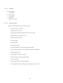
1. GENERAL.................................................................................................................................................................1-1
1.1 GENERAL ...............................................................................................................................................................1-1
1.2 DEVICE CONFIGURATION ........................................................................................................................................1-3
1.2.1 Outer View......................................................................................................................................................1-3
1.2.2 Components....................................................................................................................................................1-4
2. SPECIFICATIONS ...................................................................................................................................................2-1
2.1 FUNCTIONAL SPECIFICATIONS .................................................................................................................................2-1
2.2 ENVIRONMENTAL SPECIFICATIONS ..........................................................................................................................2-2
3. OPERATION ............................................................................................................................................................3-1
3.1 REMOVING THE SHIPPING BRACKET .........................................................................................................................3-1
3.2 POWER ON/OFF ......................................................................................................................................................3-3
3.3 INDICATION PANEL .................................................................................................................................................3-3
3.4 SETTING THE SCSI ID AND CONNECTING THE INTERFACE CABLE .............................................................................3-4
3.4.1 SCSI Cable Connection ..................................................................................................................................3-5
3.5 PAPER SPECIFICATIONS ...........................................................................................................................................3-7
3.5.1 Paper Size.......................................................................................................................................................3-7
3.5.2 Paper conditions.............................................................................................................................................3-7
3.5.2.1 ADF...........................................................................................................................................................................3-7
3.5.2.2 FIatbed.......................................................................................................................................................................3-8
3.5.2.3 Items to avoid.............................................................................................................................................................3-8
3.5.3 Readable area ................................................................................................................................................3-9
3.6 DOCUMENT SETTING METHOD ..............................................................................................................................3-10
3.6.1 Flatbed .........................................................................................................................................................3-10
3.6.1.1 When the document size is of letter/A4 size or smaller .............................................................................................3-10
3.6.1.2 When the document is a thick book ..........................................................................................................................3-11
3.6.2 ADF..............................................................................................................................................................3-11
3.6.2.1 Setting the ADF paper chute.....................................................................................................................................3-11
3.6.2.2 Placing the documents on the ADF paper chute ........................................................................................................3-12
3.7 CLEANING ............................................................................................................................................................3-14
3.7.1 Cleaning the document cover and the document glass...................................................................................3-14
3.7.2 Cleaning inside the ADF...............................................................................................................................3-15
4. INTERFACE .............................................................................................................................................................4-1
4.1 PHYSICAL SPECIFICATIONS ......................................................................................................................................4-3
4.1.1 Connection .....................................................................................................................................................4-3
4.1.2 Physical Specification.....................................................................................................................................4-4
4.1.3 Termination ....................................................................................................................................................4-4
4.1.4 Pin assignments ..............................................................................................................................................4-5
4.2 SCSI BUS ..............................................................................................................................................................4-6
4.2.1 System configuration ......................................................................................................................................4-6
4.2.1.1 System configuration ..................................................................................................................................................4-6
4.2.1.2 Addresses of SCSI devices..........................................................................................................................................4-6
4.2.1.3 Peripheral equipment .................................................................................................................................................4-6
4.2.2 Bus signals .....................................................................................................................................................4-7
4.2.3 Bus signal drive conditions .............................................................................................................................4-8
4.3 BUS PHASES ...........................................................................................................................................................4-9
4.3.1 BUS FREE phase..........................................................................................................................................4-11
4.3.2 ARBITRATION phase ...................................................................................................................................4-12
4.3.3 SELECTION phase .......................................................................................................................................4-14
4.3.4 INFORMATION TRANSFER phases .............................................................................................................4-15
4.3.4.1 Asynchronous information transfer ...........................................................................................................................4-16
4.4 COMMANDS..........................................................................................................................................................4-18
4.4.1 RESERVE UNIT command............................................................................................................................4-19
4.4.1.1 RESERVE UNIT command: COMMAND phase (initiator Õ target).........................................................................4-20
4.4.2 RELEASE UNIT command............................................................................................................................4-21
4.4.2.1 RELEASE UNIT command: COMMAND phase (initiator → target).........................................................................4-21
iii
4.4.3 INQUIRY command ......................................................................................................................................4-22
4.4.3.1 INQUIRY command: COMMAND phase (initiator → target) ...................................................................................4-22
4.4.3.2 Inquiry data: DATA IN phase (target → initiator) .....................................................................................................4-24
4.4.4 REQUEST SENSE command.........................................................................................................................4-26
4.4.4.1 REQUEST SENSE command: COMMAND phase (initiator → target) .....................................................................4-26
4.4.4.2 Sense data: DATA EN phase (target → initiator) ......................................................................................................4-27
4.4.5 SEND DIAGNOSTIC command ....................................................................................................................4-29
4.4.5.1 SEND DIAGNOSTIC command: COMMAND phase (initiator → target) .................................................................4-30
4.4.5.2 Contents of self-test..................................................................................................................................................4-31
4.4.5.3 Results of self-test....................................................................................................................................................4-31
4.4.6 TEST UNIT READY command ......................................................................................................................4-31
4.4.6.1 TEST UNIT READY command: COMMAND phase (initiator → target) ..................................................................4-32
4.4.6.2 Acknowledgment......................................................................................................................................................4-32
4.4.7 SET WINDOW command ..............................................................................................................................4-33
4.4.7.1 SET WINDOW command: COMMAND phase (initiator → target)...........................................................................4-33
4.4.7.2 Window date: DATA OUT phase (initiator → target) ...............................................................................................4-34
4.4.7.3 Update of ScanPartner 600C OEM manual ...............................................................................................................4-39
4.4.7.4 B&W Scanning Vender unique parameters ...............................................................................................................4-39
4.4.7.4.1 Vendor unique identification code: Byte 28 .......................................................................................................4-40
4.4.7.4.2 Paper size: byte 35 ............................................................................................................................................4-40
4.4.7.5 Color Scanning Vender unique parameters ...............................................................................................................4-41
4.4.7.5.1 Vendor unique identification code: Byte 28 .......................................................................................................4-41
4.4.7.5.2 Parameter length: Byte 29 .................................................................................................................................4-41
4.4.7.5.3 Color scanning parameters ................................................................................................................................4-41
4.4.8 OBJECT POSITION command......................................................................................................................4-43
4.4.8.1 OBJECT POSITION command: COMMAND phase (initator → target) ....................................................................4-44
4.4.8.2 Acknowledgment......................................................................................................................................................4-45
4.4.8.3 ADF sequence ..........................................................................................................................................................4-46
4.4.9 READ command ...........................................................................................................................................4-46
4.4.9.1 READ command: COMMAND phase (initiator → target).........................................................................................4-47
4.4.9.2 DATA IN phase (target → initiator) .........................................................................................................................4-48
4.4.10 Scan command............................................................................................................................................4-49
4.4.10.1 SCAN Command phase (initiator → target) ............................................................................................................4-49
4.5 STATUS: STATUS PHASE (TARGET → INITIATOR)..................................................................................................4-50
4.6 MESSAGES ...........................................................................................................................................................4-51
4.6.1 ATN detection...............................................................................................................................................4-51
4.6.2 Message types...............................................................................................................................................4-52
4.6.2.1 COMMAND COMPLETE (X'00'): MESSAGE IN phase (target → initiator) ............................................................4-52
4.6.2.2 INITIATOR DETECTED ERROR (X'05'): MESSAGE OUT phase (initiator → target).............................................4-52
4.6.2.3 ABORT (X'06'): MESSAGE OUT phase (initiator → target).....................................................................................4-53
4.6.2.4 MESSAGE REJECT (X'07'): MESSAGE IN/OUT phase (initiator → target) ............................................................4-53
4.6.2.5 NO OPERATION (X'08'): MESSAGE OUT phase (initiator → target)......................................................................4-54
4.6.2.6 MESSAGE PARITY ERROR (X'09'): MESSAGE OUT phase (initiator → target)....................................................4-54
4.6.2.7 BUS DEVICE RESET (X'0C'): MESSAGE OUT phase (initiator → target) ..............................................................4-54
4.6.2.8 IDENDIFY (X'80' TO X'FF'): MESSAGE OUT phase (initiator → target).................................................................4-55
4.7 COMMAND SEQUENCE ..........................................................................................................................................4-56
4.7.1 Initial sequence ............................................................................................................................................4-56
4.7.2 Read sequence ..............................................................................................................................................4-57
4.7.2.1 Read sequence for B&W mode .................................................................................................................................4-57
4.7.3 READ command sequence ............................................................................................................................4-57
4.7.3.1 Single READ ...........................................................................................................................................................4-57
4.7.3.2 Multiple READ........................................................................................................................................................4-58
4.8 STATUS TRANSITION OF LOGICAL UNIT .................................................................................................................4-59
4.9 ERROR TABLE ......................................................................................................................................................4-60
4.10 ITEMS FOR SPECIFYING WINDOW .........................................................................................................................4-61
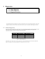
5. DIAGNOSTICS.........................................................................................................................................................5-1
5.1 ONLINE DIAGNOSTICS .............................................................................................................................................5-1
5.2 OFFLINE DIAGNOSTICS ............................................................................................................................................5-2
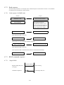
5.3 DIAGNOSTIC FLOWCHARTS ......................................................................................................................................5-3
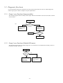
5.3.1 Group 1 error flowchart (Lamp assembly).......................................................................................................5-3
5.3.2 Group 2 error flowchart (Flatbed/ADF motor)................................................................................................5-3
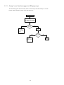
5.3.3 Group 3 error flowchart (paper in ADF paper tray)........................................................................................5-4
iv
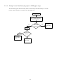
5.3.4 Group 3 error flowchart (no paper in ADF paper tray) ...................................................................................5-5
v
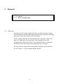
1. General
1.1 General
1.2 Device Configuration
1.1 General
Scan Partner 600C image scanners produce excellent electronic images
from documents using the high quality optical image scanning technology
and output to the host system via SCSI interface.
On the standard flat-bed, the Scan Partner 600C can scan a single loose
page or a single page of a bound book. The standard flat-bed can
accommodate a letter size/A4 page. The Scan Partner has an automatic
document feeder (ADF) that can accommodate up to 50 pages.
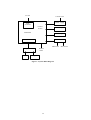
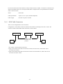
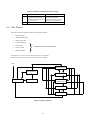
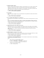
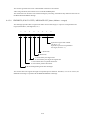
The Scan Partner outputs data on the Small Computer System Interface
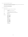
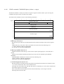
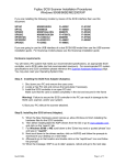
(SCSI). Figure 1.1 is the functional block diagram.
1-1
To host
110/220 VAC
Power supply
SCSI
controller
Control
section
LED display
Mainboard
Sensor input
Video Circuit
ADF section
ADF motor ADF sensor
Optical unit
Inverter
Flatbed
motor
Lamp unit
Figure 1-1 System Block Diagram
1-2
1.2 Device Configuration
1.2.1
Outer View
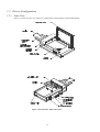
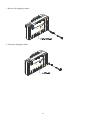
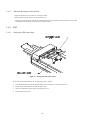
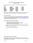
Figure 1.2 shows the outer view and device configuration of the ScanPartner 600C/OEM SP600C.
Figure 1-2 ScanPartner 600C Outer View
1-3
1.2.2
Components
1. Document Cover
The document cover holds the document in place during scanning so that the document does not move.
2. Document glass
Place the document to be read on the document glass.
3. Automatic document feeder (ADF)
The automatic document feeder (ADF) feeds documents in the scanner automatically.
4. Paper tray extension
The extension prevents documents from bending.
5. Power switch
The power switch is used to turn the scanner on and off.
6. LED panel
The LED panel indicates the status of the scanner (Power, Ready, and Jam).
7. Input paper chute
The input paper chute stacks the documents to be fed by the ADF.
8. ADF open/close lever
The ADF open/close lever is used to open and close the ADF to remove paper jammed in the ADF.
9. Power connector
The power cable is connected to the power connector to supply the scanner with AC power.
10. SCSI interface connector
The interface is connected to the interface connector. The scanner is connected to the host system
through the interface cable.
1-4
2. Specifications
2.1
2.2
Functional Specifications
Environmental Specifications
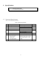
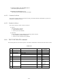
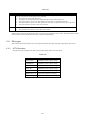
2.1 Functional Specifications
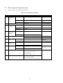
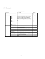
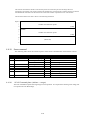
Table 2.1 lists the functional specifications.
Table 2-1 Functional Specifications
No.
1
2
3
Item
Technology
Operating method
Maximum document size
4
5
6
Light source
Optical resolution
Scanning speed
7
8
9
Gray scale
Halftone
Automatic document feeder
1. Paper chute capacity
2. Stacker capacity
3. Reading speed
4. Paper empty detection
5. Cover open detection
Interface
10
Specifications
CCD linear image sensor
Flatbed scanning/ADF scanning
Legal (11x14) for ADF
Letter/A4 for flatbed
Cold cathode fluorescent lamp
600 x 1200 dpi
Letter: 3 sec/200 dpi
A4: 3.2 sec/200 dpi
Legal: 3.5 sec/200 dpi
256 steps, 16 steps
Provides four halftone patterns
Maximum 50 pages (legal, 14-28 lbs.)
Maximum 50 pages (legal, 14-28 lbs.)
Letter size paper 200 dpi = 15 ppm
Provided
Provided
SCSI 2
2-1
Remarks
4.2 MHz
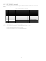
2.2 Environmental Specifications
Table 2.2 lists the environmental specifications.
Table 2-2 Environmental Specifications
No.
1
2
3
4
5
Item
Physical
dimension
(mm)
Weight
Power
requirements
Power
consumption
(watts)
Height
Specifications
165 ± 2mm
Remarks
6.3 ± 0.08 inches
Width
568 ± 2mm
Depth
348 ± 2mm
13.3 kg
100- 240V (Auto switching)
22.36 ± 0.08
inches
13.7 ± 0.08 inches
24.89 lbs
Voltage (VAC)
Frequency (Hz)
Power cable
length (m)
Operaing
Non-opearting
Acoustic noise (dB)
6
Temperature
(ºC)
7
Relative
humidity (%)
47 to 63
3 or less
35 watts
Operating
13 watts
Operating: 56 dBA or less
Standby: 46 dBA or less
10 to 40ºC (50ºF to 104ºF)
Non-operating
Operating
-40 to 60ºC(-40ºF to 140ºF)
10% to 90% RH
Non-operating
Operating
10 to 90 RH
0.25
8
Vibration (G)
9
Non-operating
Safety Regulations
1.0
UL1950, 3rd Edition
CSA C22-2 No. 950-M93
European Norm
EN 60950: 1988+A1+ A2
10
EMC
FCC Part 15 Subchapter J Class B
DOC Class B (Canada)
European Directive 89/336 (CE-Mark)
2-2
Gradient: 10ºC/hr.
(18ºF/hr.)
No condensation
5-22-500 Hz
Direction = 3 Axial
3. OPERATION
3.1
3.2
3.3
3.4
3.5
3.6
3.7
Removing the Shipping Bracket
Power On/Oft
Indication Panel
Setting the SCSI-ID and Connecting the Interface Cable
Paper Specifications
Document Setting Method
Cleaning
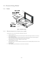
3.1 Removing the Shipping Bracket
The scanner has a bracket that fixes the position of the carrier unit during transportation. The bracket must be
removed from the base of the scanner.
If the power is turned on before the bracket has been removed, the Alarm lamp turns on. Before proceeding,
turn off the power, disconnect the power cable, and remove the bracket.
CAUTION
Do not turn the scanner upside down when removing the bracket.
3-1
1. Remove the shipping retainer
2. Fasten the shipping retainer
3-2
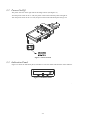
3.2 Power On/Off
The power switch is on the right side of the image scanner (See Figure 3.1)
Turn the power switch to the “I” side, the power LED on the indication panel will light on.
Turn the power switch to the “O” side, the power LED on the indication panel will go out.
Figure 3-1 Power Switch
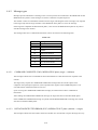
3.3 Indication Panel
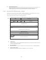
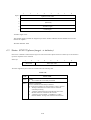
Figure 3.2 shows the indication panel, and Table 3.1 lists the names and functions of the indicator.
Figure 3-2 Indication Panel
3-3
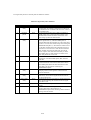
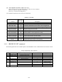
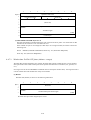
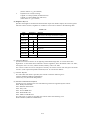
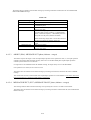
Table 3-1 Names and functions of the indicators
Name
Power
Ready
Paper jam
Color
Amber
Green
Red
Function
Lights on when the power is turned on
Lights on when the scanner is ready to receive commands from the host computer
Lights on when paper jam occurs. This indicator along with Ready indicator also indicates other
error conditions. See Chapter 5 Test Mode for details.
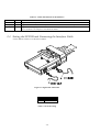
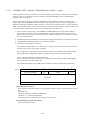
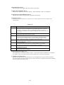
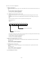
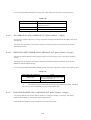
3.4 Setting the SCSI ID and Connecting the Interface Cable
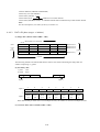
Use the address switches to set the device address.
Figure 3-3 Signal cable connection
ID
0 to 7
8
Content
Available
Offline self-test
Table 3-2 SCSI ID setting
3-4
The devices linked to the SCSI interface are daisy-chained with one another. A terminator is attached to the
ends of the interface cable. User can buy the SCSI cable in computer stores. The specifications of the SCSI
cable is as shown below.
3.4.1
Name:
SCSI Cable
Cable Specification
50 pins to 25 or 50 pins, shielded Amphenol
Cable Length:
Less than or equal to 6 meters.
SCSI Cable Connection
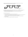
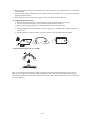
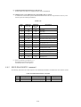
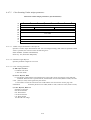
There are two configurations for the connection.
Configuration I: The number of devices attached to the SCSI bus (including the host PC) is three. The
scanner is located in the middle of the connection, as shown below.
Host PC
Scanner
SCSI device
Set terminator
switch at “off”
position
Terminator
Terminator
1. Set scanner’s SCSI terminator switch off.
2. Plug one end of the SCSI cable into the SCSI connector of the host PC, and the other end of
the cable to the scanner.
3. Plug one end of the SCSI cable into the SCSI connector of the third device, and the other end of
the cable to the other scanner.
3-5
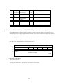
Configuration II: the number of devices attached to the SCSI bus (including the host PC) is three. The
scanner is located at the end of the connection, as shown below.
Host PC
SCSI device
Scanner
Set terminator switch at “on”
position
Terminator
If there is already another device linked to the host via SCSI cable, remove the terminator from that device. If
the terminator can not be removed, it is recommended that the connection of Configuration I be used.
1. Set scanner’s SCSI terminator switch on
2. Plug one end of the SCSI cable to one female connector of the previous device or the host.
SCSI specifications require that:
1.
Only one terminator may be attached to each end of the daisy chain.
2.
The total length of the daisy chain must not exceed 6 meters. The vendor suggests that the SCSI cable be two
or three meters in length to allow other devices to be attached to the SCSI bus.
3.
Each device on the chain will be assigned a different ID. Devices with the same SCSI ID will cause
them to malfunction.
4.
There is no restriction on the position of the devices on the daisy chain.
3-6
3.5 Paper Specifications
This section provides the readable paper specifications for the automatic document feeder (ADF).
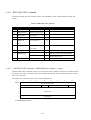
3.5.1
Paper Size
A
Feeding direction
Maximum
A
B
216
356
Minimum
A
B
100
100
Unit: mm
Figure 3-4 Paper size specifications
3.5.2
3.5.2.1
Paper conditions
ADF
a) Paper quality
Wood-free paper
PPC paper; Specified by XEROX Corporation
b) Paper specifications
Legal size, 14~28 lbs
3-7
B
3.5.2.2
FIatbed
(a) Paper quality
No condition
(b) Ream weight
No condition
(C) Paper form
Square is preferred.
3.5.2.3
Items to avoid
Paper such as the following cannot be fed by ADF.
(a) Paper with clips or staples.
(b) Paper with ink not dry.
(C)Paper with inconsistent thickness, such as an envelope.
(d) Paper with large rumples or curls.
(e)Paper with folds or tears.
(f) Tracing paper.
(g) Coating paper.
(h) Carbonless paper.
(i) Paper smaller than A5 size or larger than A4 width.
(j) Items other than paper, such as clothes, metal sheet, or OHP film.
(k) Photographic paper.
(1) Paper that has notches on its side.
(m)Paper that has a shape other than square.
(n) Very thin paper.
(o) Important document not to be damaged.
Use the flatbed to perform scanning when reading paper of items e to o.
3-8
3.5.3
Readable area
216
356
Feeding direction
Figure 3-5 ADF readable area
3-9
Unit: mm
3.6 Document Setting Method
3.6.1
Flatbed
Figure 3-6 Flatbed reading
3.6.1.1
When the document size is of letter/A4 size or smaller
If the document is to be read on the flat-bed, following the steps below.
1.
2.
3.
4.
5.
6.
Open the document cover.
Put the document on the document glass with the image face down with the upper end to the left. Correct any
curls or folded documents.
Position the left side and upper end of the document in line with the reference frame so that the upper-left
comer of the document coincides with the upper-left of the reference frame.
If the document is not set correctly, reading is not done correctly.
Close the document cover slowly.
If the document cover is closed too quickly, the document may be moved. During reading, do not press or open
the document cover.
Start the reading.
After reading ends, open the document cover and remove the document.
3-10
3.6.1.2
When the document is a thick book
1. Open the document cover and place it on the glass surface.
2. If the document is thick, do not close the document cover.
That part of the document in close contact with the glass will be read correctly but any part that is not in contact
with the glass may be unclear or distorted so care must be taken.
3.6.2
3.6.2.1
ADF
Setting the ADF paper chute
Figure 3-7 Setting the ADF paper chute
To use ADF to read the documents, set the ADF paper chute as follows:
1.
Raise the unattached end of the input paper chute to about 45 degrees, as shown in Figure 3.7.
2.
Pull down the metal bracket from under the paper chute.
3.
Click the metal bracket into the grips on the document cover.
4.
Pull the chute extension up.
3-11
3.6.2.2
Placing the documents on the ADF paper chute
Perform the following steps to place the document in the ADF paper chute. If these steps are not followed
closely, a feed error may occur.
Figure 3-8 Placing the document on the ADF paper chute
1. Place the document upside-down.
2. Angle the document sheets as shown. (See "Angling the document sheets" that follows for an
explanation of this procedure.)
3. Spread open the right and left guides of the ADF paper chute, and set them approximately 5 mm wider
than the document width.
3-12
4. Place the document face down on the ADF paper chute, and put the ends of the bottom 2 or 3 sheets into
the auto feeder.
5. C]ose the right and left guides against side of the document. (Skewing may occur if a gap exists between
the guides and document.)
6. Slide the pages down into the chute until they hit the far end of the auto feeder hole.
(a) Angling the document sheets
1. Place the document face down on a flat surface, with the top of the page to the left (a).
2. Lift the sheets with both hands. Take a maximum 4 mm thickness of sheets.
3. Hold the sheets tightly with your left hand and bend the sheets as shown in (b).
4. Then grip tightly with your right hand, loosen the grip of your left hand, and straighten the sheets as
shown in (c).
5. Repeat operations 3 and 4 as often as necessary with the entire document has been angled.
(b) Separating the sheets for easy feeding
Take a 2 to 4 mm thickness of sheets. Lightly hold both ends with both hands. Bend the sheets as shown.
Hold the sheets tightly with both hands then straighten the sheets. This operation separates the sheets for
easy feeding into the ADF. Repeat this operation two or three times. Turn the stack of sheets over and repeat
the entire operation.
3-13
3.7 Cleaning
3.7.1
Cleaning the document cover and the document glass
Use a clean and soft cloth moistened with non-corrosive solvent such as alcohol (with purity above 99.5%)
and wipe the document cover and flatbed document glass slightly, as shown in Figure 3.9.
Figure 3-9
3-14
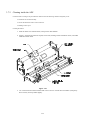
3.7.2
Cleaning inside the ADF
Clean the ADF according to the procedure that follows when the following situations frequently occur:
• Documents are not fed smoothly.
• Several documents are fed in at the same time.
• Reading result is poor.
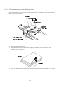
Cleaning Procedure:
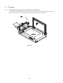
1. Push the ADF cover release button, and open the ADF module.
2. Figure 3.10 shows the locations of pad, scrub roller, feeding rollers and follow rollers, and ADF
calibration white sheet.
Figure 3-10
3. Use a clean and soft cloth moistened with a non-corrosive solvent like ALCOHOL (with purity
above 99.5%) and wipe them slightly.
3-15
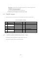
4. INTERFACE
4.1
4.2
4.3
4.4
4.5
4.6
4.7
4.8
4.9
4.10
Physical Specifications
SCSI Bus
Bus Phases
Commands
Status: STATUS phase (target initiator)
Messages
Command Sequence
Status Transition of Logical Unit
Error Table
Items for Specifying Window
This image scanner and the host are connected via an 8-bit parallel interface. The interface follows the
ANSI (American National Standards Institute) SCSI 2 (Small Computer System Interface 2) Revision 10c.
This chapter provides an overview of SCSI (minimum information necessary for understanding this
scanner), as well as descriptions peculiar to the scanner. For details of SCSI, refer to the ANSI standard,
The following terms are needed to understand this section.
SCSI device:
A host adapter or a target controller that can he attached to the SCSI bus
Initiator: An SCSI device (usually a host system) that requests an I/O process to be performed by
another SCSI device (a target).
Target:
An SCSI device that performs an operation requested by an initiator
Logical Unit:
A physical or virtual peripheral device that is addressable through a target
Range of support
1. System Configuration
This scanner operates under the multiinitiator, multitarget environment. An initiator function is not
provided. This scanner incorporates an integrated target and logical unit (image scanner).
SCSI-ID:0 to 7, variable by DIP switch Logical unit number (LUN): 000, fixed
2.Bus phases
This scanner supports all phases except reselection phase.
4-1
3.
Commands
The following commands are supported by this scanner:
•
INQUIRY
•
OBJECT POSITION
•
READ
•
RELEASE UNIT
•
REQUEST SENSE
•
RESERVE UNIT
•
SEND DIAGNOSTIC
•
SET WINDOW
•
TEST UNIT READY
•
SCAN
A control byte is not supported. If value other than X’OO' is specified. an error is generated.
4.
Statuses
The following statuses are supported by this scanner:
5.
•
BUSY
•
CHECK CONDITION
•
GOOD
•
RESERVATION CONFLICT
Messages
The following messages are supported by this scanner:
6.
•
ABORT
•
BUS DEVICE RESET
•
COMMAND COMPLETE
•
IDENTTIY
•
INITIATOR DETECTED ERROR
•
MESSAGE PARITY ERROR
•
MESSAGE REJECT
•
NO OPERATION
Others
The bits and fields for which the word 'Reserved" is described are checked. For a non-zero, an error is
returned.
4-2
4.1 Physical Specifications
The devices linked to this interface are daisy chained with each other. A terminator is attached to the ends of
the interface cable. Interface specifications are as shown below
4.1.1
Connection
SCSI device
SCSI device
Terminator
SCSI device
Terminator
4-3
4.1.2
Physical Specification
Table 4-1 SCSI physical specifications
Item
Driver/Receiver
Connector
Cable
Signal level
Max. cable length
Characteristic impedance
Cable type
Stub wire
Terminator
Driver/receiver
Output characteristics
Input characteristics
Connector pin assignments for lines
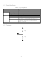
4.1.3
Specifications
Single-ended
50 Contact Shielded Low Density
6m
132 Ω
25 signal twisted pair
≤ 0.1 mm (from main cable in scanner to internal wiring)
See the figure under (3).
Open collector or three-state driver
Low level (true) = 0.0 to 0.5 VDC High Level (false)=2.5 to 5.25 VDC
Output current = 48 mA (corresponding output voltage ≤ 0.5V)
Low level (true) = 0.0 to 0.8 VDC High level (false) = 2.0 to 5.25
VDC Input load = -0.4 mA max. (at 0.4V input voltage Input
hysteresis = 0.2 VDC min.
See (4).
Termination
220Ω
330Ω
4-4
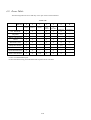
4.1.4
Pin assignments
Physical Specifications
Signal Name
Pin Number
Signal Name
GND
1
26
-DB (0)
GND
2
27
-DB(1)
GND
3
28
-DB(2)
GND
4
29
-DB(3)
GND
5
30
-DB(4)
GND
6
31
-DB(5)
GND
7
32
-DB(6)
GND
8
33
-DB(7)
GND
9
34
-DB(P)
GND
10
35
GND
GND
11
36
GND
Reserved
12
37
Reserved
(Open)
13
38
TERMPWR
Reserved
14
39
Reserved
GND
15
40
GND
GND
16
41
-ATN
GND
17
42
GND
OND
18
43
-BSY
OND
19
44
-ACK
GND
20
45
-RST
GND
21
46
-MSG
GND
22
47
-SEL
GND
23
48
-C/D
GND
24
49
-REQ
GND
25
50
-I/O
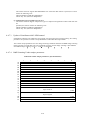
Note: Reserved pins are connected to GND.
Figure 4-1Pin assignment
4-5
4.2 SCSI Bus
4.2.1
System configuration
4.2.1.1
System configuration
The SCSI bus connects up to eight SCSI units, each linked with a daisy chain. Both ends of the daisy chain require a
terminator.
Each SCSI unit operates as an initiator or a target, so that a series of operations are performed between an initiator
and target pair.
The system may be configured with any combination of initiators and targets as long as the number of the initiators
and targets combined does not exceed eight.
4.2.1.2
Addresses of SCSI devices
Every SCSI device on the bus is assigned a unique address (SCSI ID) that corresponds to the data bus bit number;
ID#7 through ID#10 correspond to DB7 through DB0. The SCSI ID provides identification for specifying particular
SCSI device when an initiator selects a target or when a target reconnects an initiator.
SCSI ID also represents the priority for using the bus in the arbitration phase. (A description regarding the bus phase
is given later;) Priorities are given in the descending order of data bus bit numbers (DBn), with the highest priority
placed on ID#7(DB7) and the lowest priority on ED#0(DB0).
4.2.1.3
Peripheral equipment
With the basic specification, an initiator can designate up to eight peripheral devices (logical units) belonging tt a
single target, where the peripheral devices are used as the I/O units of the initiator; Logical units are identified and
selected by specifying their LUNs (logical unit numbers) in the IDENTIFY message or command (CDB: command
descriptor block).
This scanner is equipped with a target and a logical unit, and its LUN is 000.
4-6
4.2.2
Bus signals
Table 4-2 Bus signals
Signal name
Data
Control Signals
Type of signal
DB0
DB1
DB2
DB3
DB4
DB5
DB6
DB7
(Data Bus n)
DBP
(Data Bus Parity)
BSY (Busy)
Eight data-bit signals, plus a parity-bit signal that forms a DATA
BUS. DB(7) is the most significant bit and has the highest
priority during the ARBITRATION phase. Bit number,
significance and priority decease downward to DB(O). A data bit
is defined as one when the signal value is true. A data bit is
defined as zero when the signal value is false. Data parity DB(P)
shall be odd. Parity is undefined during the ARBITRATION
phase.
An "ORtied" signal that indicates that the bus is being used
SEL (Select)
An "ORtied" signal used either by an initiator to select a target or
by a target to reselect an initiator
RST (reset)
An "ORtied" signal that indicates the RESET condition
C/D (Control/Data)
I/O (Input/Output)
MSG Message
REQ (request)
The C/D, I/O, and MSG signals are used to distinguish between
the different information transfer phases.
ACK (acknowledge)
ATN (Attention)
A signal driven by an initiator to indicate a request for a
REQ/ACK data transfer handshake
A signal driven by an initiator in indicate and acknowledgment
for REQ/ACK data transfer handshake.
A signal driven by an initiator to indicate the ATTENTION
condition
4-7
Initiator
⇐
⇒
Target
⇐
⇒
⇐
⇒
⇐
⇒
⇐
⇒
⇐
⇐
⇒
⇒
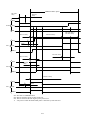
4.2.3
Bus signal drive conditions
SCSI devices drive signals of the SCSI bus. The types of SCSI devices are summarized in the following table, showing
the signals that they can drive for each operating phase of the interface.
There are two kinds of signal driving methods, OR tied and NON-OR tied, as shown in Table 4.2. During an interface
operating sequence. the BSY signal could be driven simultaneously by two or more SCSI units when the data bus is in
the ARBITRATION or RESELECTION phase. This situation also occurs with the RST signs (Reset). These two signals
must be ORtied. For other signals, either of the two methods may be used: further more, different drive methods may
coexist for a signal on the bus.
Table 4-3 Bus phases vs. signal drive sources (1/2)
Signal
C/D
DB7 to 0
Bus phase
BSY
SEL
'10
MSG
REQ
ACK
DBP
ATN
RST
BUSFREE
N
N
N
N
N
N
N
N
A
ARBITRATION
A
W
N
N
N
N
ID
N
A
SELECTION
I&T
I
N
N
N
I
I
I
A
RESELECTION
l&T
T
T
T
T
I
T
I
A
COMMAND
T
N
T
T
T
I
I
I
A
DATAIN
T
N
T
T
T
I
T
I
A
DATAOUT
T
N
T
T
T
I
I
I
A
STATUS
T
N
T
T
T
I
T
I
A
MESSAGE IN
T
N
T
T
T
I
T
I
A
MESSAGE OUT
T
N
T
T
T
I
I
I
A
N:
The signal shall be released, since it is not being driven by any SCSI device.
A:
I:
T:
W:
ID:
The signal shall be driven by all SCSI devices that are actively arbitrating.
If driven, this signal be driven only by the active initiation
If the signal is driven, it shall be driven only by the active target.
The signal shall be driven by the one SCSI device that wins arbitration.
A unique data bit (the SCSI ID) shall be driven by each SCSI device that is actively arbitrating.
The other seven data bits shall be released (shall not be driven) by this SCSI device. The parity bit
(DB(P)) may be released or driven to the true state, but shall never be driven to the false state
during this phase.
The initiator and target drive the signal according to the interface operating sequence. The
RESELECTION phase includes a sequence in which the initiator and target simultaneously drive
the signal.
I&T:
The signal shall be driven by the initiator, target, or both, as specified in the SELECTION phase and RESELECTION
phase.
4-8
Table 4-4 Method of driving the interface signal
False
True
OR connection
NON_OR connection
The signal is driven false by
No signal is driven by any
a certain SCSI device
SCSI device. Signal status is
made false by the termination (initiator or target), or is not
driven by any SCSI device
resistor circuits.
A SCSI device drives the signal true.
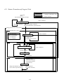
4.3 Bus Phases
The SCSI architecture includes the following eight distinct phases:
•
BUS FREE phase
•
ARBITRATION phase
•
SELECTION phase
•
COMMAND phase
•
DATA phase
•
STATUS phase
•
MESSAGE phase
}
INFORMATION TRANSFER phase
The SCSI bus can never be in more than one phase at any given time.
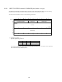
The following diagram shows how each phase transmits to another.
Reset
MESSAGE OUT
SELECTION
COMMAND
BUS FREE
DATA IN or
DATA OUT
ARBITRATION
STATUS
MESSAGE IN
Figure 4-2 Phase sequence
4-9
The signal delay times for each bus phase are defined as follows-
Table 4-5 Signal delay times definition
No.
1
Item
Arbitration
delay
Time
2.4 æs
2
Assertion
period
90 ns
3
Bus Clear
delay
800 ns
4
Bus free delay
800 ns
5
Bus set delay
1.8 _s
6
Bus settle
delay
400 ns
7
Cable skew
delay
10 ns
8
Data release
delay
400 ns
9
Deskew delay
45 ns
10
Disconnection
200 æs
Definition
The minimum time an SCSI device shall wait from
asserting BSY for arbitration until the DATA BUS can
be examined to see if arbitration has been won. There is
no maximum time.
The minimum time that a target shall assert REQ (or
REQB) while using synchronous data transfers. Also,
the minimum time that an initiator shall assert ACK
while using synchronous data transfers.
The maximum time for an SCSI device to stop driving
all bus signals after: (1) The BUS FREE phase is
detected (BSY and SEL both false for a bus settle delay)
(2) SEL is received from another SCS] device during the
ARBITRATION phase (3) The transition of RST to true.
For the first condition listed. the maximum time for an
SCSI device to clear the bus is 1200 nanoseconds from
BSY and SEL first becoming both false. If an SCSI
device requires more than a bus settle delay to detect
BUS FREE phase, it shall clear the bus within a bus
clear delay minus the excess time
The minimum time that an SCSI device shall wait from
its detection of the BUS FREE phase (BSY and SEL
both false
The maximum time for an SCSI device to assert BSY
and its SCSI ID bit on the DATA BUS after it detects
BUS FREE phase (BSY and SEL both false for a bus
settle delay) for the purpose of entering the
ARBITRATION phase
The minimum time to wait for the bus to settle after
changing certain control signals as called out in the
protocol definitions
The maximum difference in propagation time allowed
between any two SCSI bus signals measured between
any two SCSI devices.
The maximum time for an initiator to release the DATA
BUS signals following the transition of the I/O signal
from false to true.
The minimum time required for deskew of certain
signals
The minimum time that a target shall wait after
releasing BSY before participating in an
ARBITRATION phase when honoring a DISCONNECT
message from the initiator
4-10
Table 4.5 Signal delay times definition
No.
11
Item
Hold time
Time
45 ns
12
Negation
90 ns
13
Power-on to
selection
time
10 sec
(recommended)
14
Reset to
selection
time
250 ms
(recommended)
15
Reset hold
25 æs
16
Selection
abort time
200 æs
17
Selection
timeout
delay
Transfer
period
250 ms
(recommended)
18
4.3.1
definition
The minimum time added between the assertion of
REQ (Or REQB) or ACK (or ACKB) and the
changing of the data lines to provide hold time in the
initiator or target while using synchronous data
transfers. REQB and ACKIB timings only apply to
optional wide data transfers.
The minimum time that a target shall negate REQ (Or
REQB) while using synchronous data transfers. Also,
the minimum time that an initiator shall negate ACK
(or ACKB) while using synchronous data transfers.
REQB and ACKB timings only apply to optional
wide data transfers.
The recommended maximum time from power
application until an SCSI target is able to respond
with appropriate status and sense data to the TEST
UNIT READY, INQUIRY, and REQUEST SENSE
commands
The recommended maximum time after a hard
RESET condition until an SCSI target is able to
respond with appropriate status and sense data to the
TEST UNIT READY, INQUIRY and REQUEST
SENSE commands
The minimum time over which RST must be kept
asserted
The maximum time required from the moment when
selection or deselection of an initiator or target is
detected until BSY is asserted
The minimum time required for an initiator or target
in the selection or deselection phase to wait for a
BSY response before it starts the timeout procedure
The minimum allowable period, during sync data
transfer, between the start of consecutive REQ pulses
and the start of consecutive ACK pulses
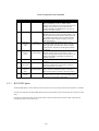
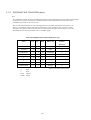
BUS FREE phase
The BUS FREE phase is used to indicate that no SCSI device is actively using the SCSI bus. and that it is available.
SCSI devices shall detect the BUS FREE phase after the SEL and BSY signals are both false for at least a bus settle
delay.
SCSI devices shall release all SCSI bus signals within a bus clear delay after the BSY and SEL signals become
continuously false for a bus settle delay.
4-11
Bus settle delay
Bus clear delay
BSY
SEL
others
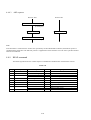
....................................................................................................................
Bus Free phase
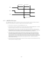
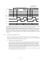
4.3.2
ARBITRATION phase
The ARBITRATION phase allows one SCSI device to gain control of the SCSI bus so that it can initiate or resume an
I/O process. The procedure for an SCSI device to obtain control of the SCSI bus is as follows:
1. The SCSI device shall first wait for the BUS FREE phase to occur;
2. The SCSI device shall wait a minimum of a bus free delay after detection of the BUS FREE phase (i.e. after the
BSY and SEL signals are both false for a bus settle delay) before driving any signal.
3 Following the bus free delay in Step 2, the SCSI device may arbitrate for the SCSI bus by asserting both the
BSY signal and its own SCSI ID, however, the SCSI device shall not arbitrate (i.e. assert the BSY signal and its
SCSI ID) if more than a bus set delay has passed since the BUS FREE phase was last observed.
4. After waiting at least an arbitration delay (measured from its assertion) the SCSI device shall examine the
DATA BUS. If a higher priority SCSI ID bit is true on the DATA BUS (DB(7) is the highest), then the SCSI
device has lost the arbitration and the SCSI device may release its signals and return to Step I. If no higher
priority SCSI ID bit is true on the DATA BUS, then the SCSI device has won the arbitration and it shall assert
the SEL signal. Any SCSI device other than the winner has lost the arbitration and shall release the BSY signal
and its SCSI ID bit within a bus clear delay after the SEL signal becomes true. A SCSI device that loses
arbitration may return to Step 1.
5. The SCSI device that wins arbitration shall wait at least a bus clear delay plus a bus settle delay after assert mg
the SEL signal before changing any signals.
4-12
ARBITRATION phase
Bus settle
delay
Bus free
delay
BSY
SCSI
SEL
DB
Bus set delay
BSY
ID7
Bus free
delay
arbitration delay
∇
SEL
DB(7)
Bus clear delay
Bus set delay
BSY
ID3
∇
Bus free
delay
SEL
DB(3)
arbitration delay
BSY
ID1
∇
Bus free
delay
SEL
DB(1)
ID7: Succeeds in ARBITRATION
ID3: Detects the SEL signals of other SCSI unit
ID1: Detects the SCSI ID with higher priority than itself
∇ : The point at which the BUS FREE phase is detected by each SCSI unit
4-13
Bus clear delay +
bus settle delay
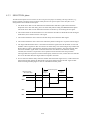
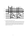
4.3.3
SELECTION phase
The SELECTION phase allows an initiator to select a target for the purpose of initiating some target function (e.g.,
READ or WRITE command). During the SELECTION phase the I/O signal is negated so that this phase can be
distinguished from the RESELECTION phase.
1. The SCSI device that won the arbitration has both the BSY and SEL signals asserted and has
delayed at least a bus clear delay plus a bus settle delay before ending the ARBITRATION phase.
The SCSI device that won the arbitration becomes an initiator by not asserting the I/O signal.
2. The initiator shall set the DATA BUS to a value which is the OR of its SCSI ID but and the target's
SCSI ID bit, and it shall assert the ATN signal.
3. The initiator shall then wait at least two deskew delays and release the BSY signal.
4. The initiator shall then wait at least a bus settle delay before looking for a response from the target.
5. The target shall determine that it is selected when the SEL signal and its SCSI ID bit are true and
the BSY and I/O signals are false for a least a bus settle delay. The selected target may examine the
DATA BUS in order to determine the SCSI ID of the selecting initiator; The selected target shall
then assert the BSY signal within a selection abort time of its most recent detection of being
selected; this assertion is required for correct operation of the selection time-out procedure.
The target shall not respond to a selection if bad parity is detected. Also, if more than two SCSI ID
bits are on the DAT BUS, the target shall not respond to selection.
6. No less than two deskew delays after the initiator detects the BSY signal is true, it shall release the
SEL signal and may change the DATA BUS. The target shall wait until the SEL signal is false
before asserting the REQ signal to enter an information transfer phase.
SELECTION phase
Bus clear delay
+ bus settle delay
Deskew
delay x 2
I/O
BSY
SEL
DB
4-14
Deskew
delay x 2
4.3.4
INFORMATION TRANSFER phases
Note:
The COMMAND, DATA, STATUS, and MESSAGE phases are all grouped together as the information transfer phases
because they are a]l used to transfer data or control information via the DATA BUS The actual content of the
information is beyond the scope of this section.
The C/D, I/O, and MSG signals are used to distinguish between the different information transfer phases (see
Table 4.5). The target drives these three signals and therefore controls all changes from one phase to another.
The initiator can request a MESSAGE OUT phase by asserting the ATN signal, while the target can cause the
BUS FREE phase by releasing the MSG, C/D, I/O, and BSY signals.
Table 4-6 INFORMATION TRANSFER phase type
Phase
C/D
I/O
MSG
DB7 to 9,P
Transfer
direction
DATA OUT
0
0
0
Data
INIT ⇒TARG
DATAIN
0
1
0
Data
⇐
COMMAND
I
0
0
Command
⇒
STATUS
I
I
0
Status
⇐
*
0
0
1
*
0
1
I
MESSAGE OUT
1
0
1
Message
⇒
MESSAGEIN
1
1
1
Message
⇐
*: Reserved for future standardization
0:
1:
INIT:
TARG:
False
True
Initiator
Target
4-15
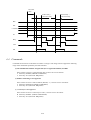
INFORMATION TRANSFER phase
Bus settle delay
Min. Ons
INFORMATION
TRANSFER phase
Bus settle delay
BSY
SEL
C/D,
MSG, I/O
REQ
ACK
DB
The INFORMATION TRANSFER phases use one or more REQ/ACK handshakes to control the information
transfer Each REQ/ACK handshake allows the transfer of one byte of information. During the
INFORMATION TRANSFER phases the BSY signal shall remain true and the SEL signal shall remain
false. Additionally, during the INFORMATION TRANSFER phases, the target shall continuously envelope
the REQ/ACK handshake(s) with the C/D, I/O and MSG signals in such a manner that these control signals
are valid for a bus settle delay before the assertion of the REQ signal of the first handshake. These control
signals remain valid until after the negation of the ACK signal at the end of the handshake of the last transfer
of the phase.
4.3.4.1
Asynchronous information transfer
The target shall control the direction of information transfer by means of the I/O signal. When the I/O
signal is true, information shall be transferred from the target to the initiator When the I/O signal is false,
information shall be transferred from the initiator to the target.
(a)
Asynchronous transfer from target to initiator
If the I/O signal is true (transfer to the initiator), the target shall first drive the DB(7-O, P) signals to
their desired values, delay at least one deskew delay plus a cable skew delay then assert the REQ
signal. The DB (7-0, P) signals shall remain valid until the ACK signal is true at the target. The
initiator shall read the DB(7-0, P) signals after the REQ signal is true then indicate its acceptance of
the data by asserting the ACK signal. when the ACK signal becomes true at the target, the target
may change or release the DB(7-O P) signals and shall negate the REQ signal. After the REQ signal
is false, the initiator shall then negate the ACK signal.
After the ACK signal is false, the target may continue the transfer by driving the DB (7-0, P) signals
and asserting the REQ signal, as previously described.
4-16
Bus settle delay
deskew delay +
cable skew delay
deskew delay +
cable skew delay
BSY
SEL
C/D,MSG
I/O
REQ
ACK
DB
(b) Asynchronous transler from initiator to target
If the I/O signal is false (transfer to the target), the target shall request information by asserting the
REQ signal. The initiator shall drive the DB (7-0, P) signals to their desired values, delay at least
one deskew delay plus a cable skew delay then assert the ACK signal. The initiator shall continue
to drive the DB (7-0, P) signals until the REQ signal is false. When the ACK signal becomes true
at the target, the target shall read the DB (7-0, P) signals then negate the REQ signal. When the
REQ signal becomes false at the Initiator, the initiator may change or release the DB (7-0, P)
signals and shall negate the ACK signal. The target may continue the transfer by asserting the
REQ signal, as previously described.
4-17
Bus settle
delay
deskew delay +
cable skew delay
deskew delay +
cable skew delay
BSY
SEL
C/D,MSG
I/O
REQ
ACK
DB
4.4 Commands
Commands are directions issued from an initiator to a target. This image scanner supports the following
range of the commands specified by the SCSI standard.
(a) The identification number of logical unit (LUN: logical unit number) is B'000.’
If this scanner receives a value other than 000, it returns an error as follows:
• Status key: B'0000l’(CHECK CONDITION)
• Sense key: X'5’(ILLEGAL REQUEST)
(b) Relative addressing is not supported.
If this scanner receives a relative address (RelAdr) =1, it returns an error as follows:
• Status key: B'OOOOl’(CHECK CONDITION)
• Sense key: X'5’(WLEGAL REQUEST)
(c) A control byte is not supported.
If this scanner receives a control byte ≠ X'00’, it returns an error as follows:
• Status key: B'0000l ’(CHECK CONDITION)
• Sense key: X'5’(ILLEGAL REQUEST)
4-18
(d) A bit and field described as "Reserved" are 0.
If this scanner receives a value other than 0, it returns an error as follows:
Status key: B'00001 '(CHECK CONDITON)
Sense key: X~5'(ILLEGAL REQUES~I)
The commands supported by this scanner are listed below.
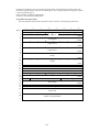
Table 4-7 Commands
Operation
Command
code (hex)
RESERVE UNIT
16
Declares the exclusive use of a logical unit
RELEASE UNIT
17
Cancels the declaration of the exclusive use of a logical unit
INQUIRY
12
Examines the information regarding the target and logical unit
REQUEST SENSE
03
Requests a target for sense data
SEND DIAGNOSTIC
ID
Requests a target for self-check
TEST UNIT READY
00
Checks whether or not a logical unit is ready
SET WINDOW
24
Sets a window
OBJECT POSITION
31
Controls the automatic document feeder
READ
28
Requests transfer of image data
SCAN
1B
Requests the target to begin a scan operation
4.4.1
Description
RESERVE UNIT command
The following table shows the normal sequence of the RESERVE UNIT command when used with this scanner.
Table 4-8 RESERVE UNIT command
Step
1
2
3
Bus phase
BUS FREE
ARBITRATION
SELECTION
Initiator operation
Verifies bus free
Obtains bus-usage right
Selects target
←→
4
5
6
7
MESSAGE OUT
COMMAND
STATUS
MESSAGE IN
Selects logical unit
Specifies RESERVE UNIT (CDB)
→
→
8
BUS FREE
Target operation
→
Drives BSY signal
←
4-19
Reports GOOD status
Reports message
(Command complete)
Releases ESY signal
4.4.1.1
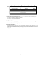
RESERVE UNIT command: COMMAND phase (initiator Õ target)
Where a logical unit can be accessed by two or more initiators, there could be interferences with command
sequences, data, etc. This situation can be avoided by issuing the RESERVE UNIT command before
initiating series of operations.
Once a logical unit has properly accepted the RESERVE UNIT command, it will be occupied by the
initiator that issued the RESERVE UNIT command. If the 3rd party reservation option is supported, the
logical unit might be occupied by another SCSI unit - one having an initiator function - which is specified
TPID. In this condition called "reserved;' the logical unit cannot be accessed from any other initiators. The
reserved condition remains effective until one of the following events take place:
1. The reservation is replaced by a new RESERVE COMMAND from the same initiator that has
reserved the logical unit. (issuing another RESERVE UNIT command with the reservation still
effective does not result in an error. The previously established reservation is released as a result of
2,3, or 4 described below.)
2. The RELEASE UNIT command is issued from the same initiator that has reserved the logical unit.
3. The BUS DEVICE RESET message is sent from any initiator.
4. A hardware reset condition is detected.
The condition in effect after 3 or 4 is indicated by a sense key X'6' (UNIT ATTENTION), which is
returned in response to a subsequent command.
When a logical unit is already reserved by another initiator, if a command other than RELEASE
UNIT, INQUIRY, or REQUEST SENSE is issued, the target returns the following status:
Status: B'01100' (RESERVATION CONFLICT)
The initiator having reserved a logical unit can change the reservation by issuing the RESERVE
UNIT command to the same logical unit.
The command descriptor block (CDB) of this command is shown in the following illustration.
7
6
Byte 0
1
4
5
3
2
1
0
Operation code X'16'
Logical unit number
TP
TPID
(Reserved)
2
3
(Reserved)
4
5
Control byte
(a) TP (third party): Byte 1
If the 3rd party reservation option is not supported, setting this bit to 1 causes the target to return
the
following error:
•Status key: B'00001 '(CIIECK CONDITION)
•Sense key: X'5' (ILLEGAL REQUEST)
This scanner does not support the 3rd party reservation option.
(b) TPID (third party device ID): Byte 1
This scanner ignores TPID.
4-20
4.4.2
RELEASE UNIT command
The following table shows the normal sequence of the RESERVE UNIT command when used with this
scanner.
Table 4-9 RELEASE UNIT command
Step
Bus phase
←→
Initiator operation
1
BUS FREE
Verifies bus free
2
ARBITRATION
Obtains bus-usage right
3
SELECTION
Selects target
Target operation
→
Drives BSY signal
4
MESSAGE
Selects local unit
→
Specifies RELEASE
→
OUT
5
COMMAND
UNIT (CDB)
6
STATUS
←
Reports GOOD status
7
MESSAGE IN
←
Reports message (Command Complete)
Releases BSY signal
8
4.4.2.1
BUSFREE
RELEASE UNIT command: COMMAND phase (initiator → target)
The RELEASE UNIT command releases a reserved status. If this command comes from an initiator that has
not declared reservation, the target ignores the command and responds with the GOOD status (the reserved
status is not released).
The CDB of this command is shown in the following illustration.
7
6
5
4
3
Byte 0
1
2
1
0
Operation code X'17'
Logical unit number
TP
2
3
(Reserved)
4
5
Control byte
(a) TP (third party): Byte 1
4-21
TPID
(Reserved)
If the 3rd party reservation option is not supported, setting this bit to 1 causes the target to return the
following error;
• Status key: B'0000I'(CHECKCONDITION)
• Sense key: X~5'(ILLEGAL REQUEST)
This scanner does not support the 3rd party reservation option.
(b) TPID (third party device ID): Byte 1 This scanner ignores TPID.
4.4.3
INQUIRY command
The following table shows the normal sequence of the INQUIRY command when used with this scanner.
Table 4-10 INQUIRY command
Step
Bus phase
Initiator operation
←→
1
2
3
BUS FREE
ARBITRATION ON
SELECTION
Verifies bus free
Obtains bus-usage right
Selects target
→
Target operation
Drives BSY signal
4
5
6
7
8
MESSAGE OUT
COMMAND
DATA IN
STATUS
MESSAGE IN
9
BUS FREE
4.4.3.1
Selects logical unit
Specifies INQUIRY (CBD)
→
→
←
←
←
Reports inquiry data
Reports GOOD status
Reports message (Command Complete
Releases BSY signal
INQUIRY command: COMMAND phase (initiator → target)
The INQUIRY command checks information regarding a target and logical unit.
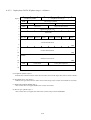
The CDB of this command is shown in the following illustration.
4-22
7
6
Byte 0
1
5
4
3
2
1
0
Operation code X'12'
Logical unit number
(Reserved)
2
Page Code
3
(Reserved)
4
Allocation length
5
Control byte
EVPD
(a) EVPD (enable vital product data): Byte 1
This scanner does not support EVPD. If this bit is set to 1, the scanner returns the following error:
• Status key: B'OOOO1 '(CHECK CONDITION)
• Sense key: X'5'(ILLEGAL REQUEST)
(b) Page code: Byte 2
This scanner does not support page code. If this bit is set to 1, the scanner returns the following error:
• Status key: B'00001'(CHECK CONDITION)
• Sense key: x'5'(ILLEGAL REQUEST)
(C)Allocation length: Byte 4
This field specifies the storage area in bytes that the initiator allocates for inquiry data. If a 0 is set here,
inquiry data is not transferred, but this is not regarded as an error. The target terminates the DATA IN
phase when it has transferred either the bytes of inquiry data specified in this field or all of effective
inquiry data.
4-23
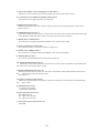
4.4.3.2
Inquiry data: DATA IN phase (target → initiator)
7
Byte 0
1
2
3
6
4
5
3
Peripheral qualifier
2
1
0
Peripheral device type
RMB
Device type qualifier
ISO version
AENC
ECMA version
ANSI approved version
Reserved
4
Response data format
Additional length (n-4)
5
(Reserved)
6
7
Rel Adr
8
(MSB)
Wbus32
Wbus16
SYNC
LINKED
CACHE
CMDQUE
SftRst
Vendor identification
F
10
LSB
(MSB)
Product identification
1F
20
LSB
(MSB)
Product revision level
23
24
LSB
ADF
Color mode
Color plane sequence
(Reserved)
5F
(a) Peripheral qualifier: Byte 0
Indicates the connection status of the devices under control of the target This scanner returns B' 000'.
(b) Peripheral device type: Byte 0
Indicates the type of the devices under control of the target. This scanner returns B'00110' (scanner).
(c) Removable medium (RMB): Byte 1
This scanner does not support RMB. This scanner returns B'0'.
(d) Device type qualifier: Byte 1
This scanner does not support this field. This scanner always returns B'0000000'.
4-24
(e) ISO version, ECMA version, ANSI approved version: Byte 2
Indicates the version number of the governing standard. This scanner returns X'02' (SCSI-2).
(f) Asynchronous event notification capability (AENC): Byte 3
This scanner does not support this field, so it returns B'0'.
(g) Response data format: Byte 3
Indicates the standard, and its version number, that governs the format of inquiry data. This scanner returns
B'0010' (SCSI-2).
(h) Additional length (n-4): Byte 4
Specifies the number of bytes, from byte 5 to the last byte. This value will not change with the allocation length
value specified in CDB. This scanner returns ~5B' (the 91 bytes from byte 5 to byte SF).
(i) RelAdr, Wbu~2, Wbusl6: Byte 7
This scanner does not support ReIAdrIwbus32(Wbusl6. This scanner returns B' 000'.
(j) SYNC (synchronous transfer): Byte 7
This scanner returns B'0' ("synchronous transfer not supported").
(k) Linked, cache, CMDQUE: Byte 7
This scanner does not support linked/cache/CMDQUE. This scanner returns B'000'.
(l) sftRst (Soft Reset): Byte 7
This scanner performs Hardware Reset. This scanner returns B'0'.
(m) Vendor identification: Bytes 8 to F
Indicates the vendor of the logical unit in ASCII code. The vendor name is left-justified, with the blank filled
with spaces (x'20'). This scanner returns "FCPA".
(n) Product identification: Bytes 10 to 1F
Indicates the product name in ASCII code. The name is left-justified, with the blank filled with spaces (X'20').
This
scanner returns one of the following names:
Scan Partner 10
(o) Product revision level: Bytes 20 to 23
Indicates the version number of the product in ASCII code. This number is left-justified, with the blank filled
with
spaces (X'20').
(p) ADF mode: Byte 24, bit 7
0: No built-in ADF module
1: With built-in ADF module
(q) Color mode: Byte 24, bit 6 to 4
000: B&W image only
001: 3-pass color scan mode
101: 1-pass color scan mode
(r) Color plane sequence: Byte 24, bit 3 to 0
0000: RGB
4-25
4.4.4
REQUEST SENSE command
The following table shows the normal sequence of the REQUEST SENSE command when used with this scanner.
Table 4-11 REQUEST SENSE command
Step
Bus phase
Initiator operation
1
BUS FREE
Verifies bus free
2
ARBITRATION
Obtains bus-usage right
3
SELECTION
Selects target
←→
Target operation
→
Drives BSY signal
4
Selects logical unit
Specifies REQUEST
SENSE (CDB)
→
→
5
MESSAGE OUT
COMMAND
6
DATA IN
←
Reports sense data
7
8
STATUS
MESSAGE IN
←
←
Reports GOOD status
Reports message
(Command Complete)
Releases BSY signal
9
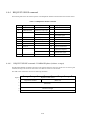
4.4.4.1
BUS FREE
REQUEST SENSE command: COMMAND phase (initiator → target)
The REQUEST SENSE command requests the sense data that shows the status of a logical unit. On receiving this
command, the target sets the unit's status in the sense data and returns it to the initiator.
The CDB of this command is shown in the following illustration.
7
6
Byte 0
1
2
5
4
3
2
Operation code X'03'
Logical unit number
(Reserved)
(Reserved)
3
4
Allocation length
5
Control byte
4-26
1
0
(a)
Allocation length: Byte 4
Specifies the storage area in bytes that tile initiator allocates for sense data If a 0 is set here, sense data is not
transferred, but this is not treated as an error. The target terminates tile DATA IN phase when it has
transferred either the bytes of sense data specified in this field or all of effective sense data.
4.4.4.2
Sense data: DATA EN phase (target → initiator)
The target creates sense data if its status is B'00001 ' (CHECK CONDITION) or if a BUS FREE error has occurred.
This scanner creates sense data when any of tile errors described later is encountered.
The sense data on this scanner is shown in tile following illustration.
7
Byte 0
6
4
5
Valid
3
2
1
Segment number
FM
EOM
ILI
(Reserved)
Sense key
(MSB)
Information bytes
(LSB)
6
Additional sense length
7
8
0
Error code
1
2
3
(MSB)
Command-specific information byte
LSB
B
C
Additional sense code
D
Additional sense code qualifier
E
Field replaceable unit code
F
SKSV
10
Sense-key specific bytes
11
(a)
Valid: Byte 0
Indicates whether or not the INFORMATION BYTES field is as specified by ANSI. This scanner
returns B'1' ("specified by ANSI").
(b)
Error code: Byte 0
Differentiates between current error or deferred error. This scanner returns X'70' ("CURRENT ERROR").
(c)
Segment number: Byte 1
This scanner does not support SEGMENT NUMBER. This scanner returns X'00'.
4-27
(d) FM (file mark): Byte 2
This scanner does not support FM. This scanner returns B'0'.
(e) EOM (end of medium): Byte 2
Indicates the completion of window reading: 1 when completed, 0 when not completed.
(f) ILI (incorrect length indicator): Byte 2
Indicates that an error in logical block length has been detected.
(g) Sense key: Byte 2
Indicates the logical unit status using a sense key. This scanner supports the sense keys shown in the
following table:
Table 4-12
Sense key
0
2
3
4
5
6
B
status of logical unit
NO SENSE
The logical unit has no information to be specifically described in a sense key.
This status occurs because either a command has succeeded, or because a
command has terminated in the CHECK CONDITION status since tile ILI bit has
been set to 1.
NOT READY
The specified logical unit cannot be accessed.
MEDIUM ERROR
A command has terminated because of a trouble with tile medium. Typical
causes of this error with this scanner are that tile ADF paper chute is empty,
paper is jammed in the ADF, or the ADF cover has been opened.
HARDWARE ERROR
An unrecoverable error was detected
ILLEGAL REQUEST
An illegal parameter exists either in a command (CDB), or in a group of
parameters sent in the DATA OUT phase following a command.
UNIT ATTENTION
The target has been reset.
ABORTED COMMAND
The target has aborted a command.
(h) Information bytes: Bytes 3 to 6
The information in this field is effective if ILI is 1. This scanner returns the remainder (2's complement
any negative value) so tile requested transfer amount subtracted by tile actual transfer amount
(i) Additional sense length: Byte 7
Specifies the number of sense bytes that follows. Even if all additional sense bytes cannot be transferred
because the allocation length in CDB is small, the value in this field is not adjusted to indicate the remaining
data. This scanner always assumes ~0A'.
4-28
(j) Command-specific information bytes: Bytes 8 to B
On this scanner, this field is not supported and is fixed to X'00000000'.
(k) Additional sense code, additional sense code qualifier: Bytes C and D
A combination of these fields specifies detailed information about the error reported in the sense key. This
scanner reports the following information:
Table 4-13
Sense
key
Additional
sense code
Additional
sense code
qualifier
Description
0
O0
00
No-sense
2
O0
00
Not ready
3
80
0l
Jam
3
80
02
ADF cover open
3
80
03
Document chute empty of paper
4
44
00
Abnormal internal target
4
47
00
SCSI parity error
5
20
00
Invalid command
5
24
00
Invalid field in CDB
5
25
00
Unsupported logical unit
5
26
00
Invalid field in parameter list
6
00
00
UNIT ATTENTION
B
43
00
Message error
(l) Sense-key specific bytes: Bytes F to 11
This field is reserved on this scanner.
(X'00000000' must not be expected.)
4.4.5
SEND DIAGNOSTIC command
The following table shows the normal sequence of the SEND DIAGNOSTIC command when used with this scanner.
Table 4-14 SEND DIAGNOSTIC command
Step
1
2
Bus phase
BUS FREE
Initiator operation
Verifies bus free
ARBITRATION ON
Obtains bus-usage right
4-29
←→
Target operation
Table 4.14 SEND DIAGNOSTIC command
Initiator operation
←→
Step
Bus phase
Target operation
3
SELECTION
Selects target
→
4
MESSAGE
OUT
COMMAND
Selects logical unit
→
Specifies SEND
DIAGNOSTIC
(CDB)
→
Performs self-test
←
←
Reports GOOD status
Reports message (Command Complete)
Drives BSY signal
5
6
7
STATUS
MESSAGE
IN
8
BUSFREE
Releases BSY signal
4.4.5.1
SEND DIAGNOSTIC command: COMMAND phase (initiator → target)
The SEND DIAGNO~C command is used by an initiator to request a target or local unit for self-test. Two types of
self-diagnostic are: (a) the selftest performed by the unit itself, and (b) the test conducted according to the instruction
data from the initiator.
This scanner supports the self-test only.
The results of self-test are reported using the status and sense da~
The CDB of this command is shown in the following illustration.
7
6
Byte 0
1
5
4
2
1
0
SLFTST
DO
UO
Operation code X'1D'
Logical unit number
PF
2
3
3
(Reserved)
Reserved
(MSB)
Parameter list length
4
5
(LSB)
Control byte
(a) PF (page format): Byte 1
This scanner ignores PF.
(b) SLFTST (selftest): Byte 1
Specifies the self-test done by the unit itself. This value is 1 on this scanner.
4-30
(C) DO (device offline), UO (unit offline): Byte 1
This scanner ignores DO and UO.
(d) Parameter list length: Bytes 3 to 4
This scanner does not support parameter list length.
4.4.5.2
Contents of self-test
The contents of self-test shall be an equivalent of NOP, provided that CHECK CONDITION is reported if err
information is withheld in the unit.
4.4.5.3
Results of self-test
This scanner reports the results of self-test as follows:
(a) Normal
The GOOD status is returned.
• Status: B'00000' (GOOD)
• Sense key: X'O' (NO SENSE).
(b) Abnormal
If error information is being withheld, the following status is returned:
• Status: B'00001' (CHECK CONDITION)
• Sense key: Error information being withheld
4.4.6
TEST UNIT READY command
The following table shows the normal sequence of the TEST UNIT READY command when used with this scanner.
Table 4-15
Step
1
2
3
Bus phase
BUSFREE
ARBITRATION
SELECTION
Initiator operation
Verifies bus free
Obtains bus-usage right
Select target
←→
Target
operation
→
Drives BSY
signal
4
5
6
MESSAGE OUT
COMMAND
STATUS
7
MESSAGE IN
8
BUS FREE
Selects logical unit
Specifies TEST UNIT READY (CDB)
→
→
←
4-31
Reports GOOD
status
Reports message
(Command
Complete)
Releases BSY
signal
4.4.6.1
TEST UNIT READY command: COMMAND phase (initiator → target)
The TEST UNIT READY command checks whether a logical unit is ready. The command does not request. The
acknowledgment of this command reported using the status and sense data.
The CDB of this command is shown in the following illustration.
7
6
Byte 0
1
4
5
3
2
Operation code X'00'
Logical unit number
(Reserved)
2
3
(Reserved)
4
Control byte
5
4.4.6.2
Acknowledgment
This scanner reports the acknowledgment of the TEST UNIT READY command as follows:
(a) When ready:
• Status: B'00000' (GOOD)
• Sense key: X'0' (NO SENSE)
(0) When not ready:
• Status: B'0000l' (CHECK CONDITION)
• Sense key: X'2' (NOT READY)
4-32
1
0
4.4.7
SET WINDOW command
The following table shows the normal sequence of the SET WINDOW command when used with this
scanner.
Table 4-16 SET WINDOW command
Step
1
2
3
Bus phase
BUS FREE
ARBITRATION
SELECTION
Initiator operation
Verifies bus free
Obtains bus-usage right
Selects target
4
5
6
7
8
(MESSAGE OUT)
COMMAND
DATA OUT
STATUS
MESSAGE IN
Selects logical unit
Specifies SET WINDOW (CDB)
Specifies window data
9
BUS FREE
←→
Target operation
→
Drives BSY signal
4.4.7.1
→
→
←
←
←
Sets window
Reports GOOD status
Reports message
(Command Complete)
Release BSY signal
SET WINDOW command: COMMAND phase (initiator → target)
The SET WINDOW command is used to set a window.
The CDB of this command is shown in the following illustration.
4-33
7
6
4
5
Byte 0
3
2
1
0
Operator code X'24'
1
Logical unit number
(Reserved)
2
(Reserved)
5
6
(MSB)
Transfer length
7
(LSB)
8
Control byte
9
(a) TRANSFER LENGTH: Bytes 6 to 8
Specifies the number of window data bytes sent in the DATA OUT phase. A 0 means that no data
transferred; this situation is not considered an error.
If the number of bytes is not enough (less than 48) to set a single window, the scanner returns the
following error
Status: B'00001' (CHECK CONDITION) Sense key: X'5' (ILLEGAL REQUEST)
Sense key: X'5' (ILLEGAL REQUEST)
4.4.7.2
Window date: DATA OUT phase (initiator → target)
Window data specifies the details of a window. Window data contains a bead and one or more window
descriptor block. Each window descriptor block specifies the attributes of a window (size, position, sca
etc.).
If a target receives the SET WINDOW command when it already has window data, ..the target discards a
current window data and validates the newly received data.
(a) Header
Window data (header) is shown in the following illustration.
7
Byte 0
5
6
6
5
4
3
2
1
0
Reserved
(MSB)
Window descriptor block length
(LSB)
7
Window descriptor block length: Bytes 6 and 7
4-34
Specifies the length in bytes of a window descriptor block. Each block has the same length. The
allowable range of length is between 40 and 248 bytes. For a length outside this range, this scanner
returns the following error:
Status: B'00001' (CHECK CONDITION)
Sense key: X'5' (ILLEGAL REQUEST)
(b) Window descriptor block
Window parameter data (window descriptor block) is shown in the following illustration.
7
Byte 0
1
2
3
4
5
6
9
A
D
E
11
12
15
16
17
18
19
1A
1B
1C
1D
1E
1F
20
21
22
27
28
n
6
5
4
3
Window identifier
2
1
0
(Reserved)
(MSB)
(MSB)
X resolution
(LSB)
Y resolution
(LSB)
(MSB)
Upper Left X
(LSB)
(MSB)
Upper Left Y
(LSB)
(MSB)
Width
(LSB)
(MSB)
Length
(LSB)
Brightness
Threshold
Contrast
Image composition
Bit per pixel
(MSB)
RIF
(MSB)
Halftone pattern
(Reserved)
Bit ordering
Compression type
Compression argument
(Reserved)
Vendor unique parameter
4-35
(LSB)
Padding type
(LSB)
(c) Window identifier: Byte 0
Specifies a unique value that identifies a window. The value may be 0 to 255. If two or more window
identifiers are specified for a single set of window data, the most recently specified identifier is
validated This scanner allows only one window to be set Therefore, only 0 may be specified in this
field. II other than 0 is specified, this scanner returns the following error:
• Status: B~0000l' (CHECK CONDITION)
• Sense key: X'5' (ILLEGAL REQUEST)
(d) Auto: Byte 1
This scanner does not support auto. If a value other than 0 is specified, this scanner returns the foIl
error:
• Status: B'0000l' (CHECK CONDITION)
• Sense key: X'5' (ILLEGAL REQUEST)
(e) X, Y resolution (XR, YR): Bytes 2 to 3 and 4 to 5
Specified here are the resolutions in the horizontal (X) and vertical (Y) scanning directions, in pixels
per
inch. If 0 is specified, the default value (300 dpi) is assumed. The acceptable resolution value is as
60, 75, 80, 100, 120, 150, 200, 240, 300, 600. If a value is specified that does not comply with these
conditions, this scanner returns the following error:
• Status: B'0000l' (CHECK CONDITION)
• Sense key: X'5' (ILLEGAL REQUEST)
(f) Upper left X,Y(ULX, ULY): Bytes 6 to 9, A to D
Specified here are the X and Y coordinates of the upper-left comer of the window. The coordinates
expressed in units of 1/1200 inches relative to the upper-left comer of the maximum scan area. If the
ULX or ULY value is outside the maximum scan area of this scanner, this scanner returns the
following error:
• Status: B'00001'(CHECK CONDITION)
• Sense key: X'5' (ILLEGAL REQUEST)
(g) Width, length (W, L): Bytes E to 11, 12 to 15
Specifies here are the width and length of the window, in units of 1/1200 inches. If the W or L value
outside the maximum scan area of this scanner; the following error is returned:
• Status: B'0000l' (CHECK CONDITION)
• Sense key: X'5' (ILLEGAL REQUEST)
The same error is also returned if this scanner is set to less than one raster line for vertical scanning
less than two bytes for horizontal scanning.
Notes:
1.
ULX, ULY, W, L versus maximum scan area:
0< (ULX + W) ó 10200 (in 1/1200 inches)
0< (ULY + L) ó 13937 (in 1/1200 inches) for flatbed scan
0< (ULY + L) ó- 16800 (in 1/1200 inches) for ADF scan
2.
Conditions for horizontal scanning:
9< {XR x W/1200] ó 5100
4-36
3.
(Values under 0 in [ ] are omitted.)
Conditions for vertical scanning:
1 ó [YR x L/1200] ò- 6968 (for flat-bed scan)
1 ó [YR x L/1200) ó 8400 (for ADF scan)
(Values under 0 in [ ] are omitted.)
(h) Brightness: Byte 16
Specifies the brightness for half-tone monochrome output. For multibit output, this scanner ignores
this field. On this scanner, brightness is variable to seven levels as shown in the following table.
Table 4-17
Value
Brightness
00
-
00 to 1F
Brighter
Remarks
Same as 80 to 9F range (with built-in dither)
20 to 3F
40 to5F
60 to 7F
80 to 9F
Digitized
A0 to BF
C0 to DF
E0 to W
Darker
(i) Threshold: Byte 17
Specifies the threshold value for use in digitizing multivalued image data. A 0 value causes auto
digitization. A value other than 0 indicates a relative brightness, where the darkest value is at X'FF',
the brightest value is at X'01', and the normal (ordinary) value is at X'80'.
This scanner is limited to 64 levels of brightness. Internally, this scanner excludes X'00' and ignores the lowest
two bits. (X'00' represents Dynamic Threshold; X'01' to X'03' are the darkest.
(j) Contrast: Byte 18
If a value other than X'00' is specified, this scanner returns the following error:
• Status: B'0000l' (CHECK CONDITION)
• Sense key: X'5' (ILLEGAL REQUEST)
(k) IMAGE COMPOSITION: Byte 19
Specifies the type of image to be read. The following values are supported by this scanner:
X'00': Binary monochrome
X'0l': Dithered monochrome
X'02': Gray scale
X'03': bi-level RGB color
X'04': Dither RGB color
X'05': Multi-level RGB color
If a value X'03' or greater is specified, this scanner returns the following error:
Status: B'00001' (CHECK CONDITION)
4-37
Sense key: X'5' (ILLEGAL REQUEST)
(I) Bit per pixel: Byte 1A
Specifies the number of bits per pixel. This value shall be X'Ol', X'04' and X'08' for this scanner. For
an:
value, this scanner returns the following error:
• Status: B'00001' (CHECK CONDITION)
• Sense key: X'5' (ILLEGAL REQUEST)
(m) Halftone pattern: Bytes lB to 1C (lB reserved)
Specifies the dithered pattern used in binarizing multibit multivalued image data. This scanner
validates
this field only with the selection of dither/half-tone monochrome or mixed mode processing. For
other
selections, this field is ignored. The values are specified in the following format:
• Byte IB: Reserved
• Byte IC
7
6
5
4
3
2
1
0
Half-tone pattern number
this bit is reserved
This scanner has four types (X'00' to X'03') of built-in pattern. If a value greater than the four range
is specified, this scanner returns the following error:
• Status: B'00001' (CHECK CONDITION)
• Sense key: X'5' (ILLEGAL REQUEST)
(n) RIF (reverse image format): Byte 1D, bit 7
This scanner does not support RIF. If a value other than X'O' is specified, this scanner returns the
following errors:
• Status: B'00001' (CHECK CONDITION)
• Sense key: X'5' (ILLEGAL REQUEST)
(o) Padding type: Byte 1D, bits 0 to 2
This scanner does not support Padding type. If a value other than X'000' is specified, this scanner
returns
the following error:
• Status: B'0000l' (CHECK CONDITION)
• Sense key: X'5' (ILLEGAL REQUEST)
(p) Bit ordering: Bytes 1E to 1F
4-38
This scanner does not support BIT ORDERING. If a value other than X'0000' is specified, this scanner
returns the following error:
• Status: B'00001' (CHECK CONDITION)
• Sense key: X'5' (ILLEGAL REQUEST)
(q) Compression type, argument: Bytes 20 to 21
This scanner does not support compression type nor compression argument If values other than X'0'
are
specified, this scanner returns the following error:
• Status: B'00001' (CHECK CONDITION)
• Sense key: X'5' (ILLEGAL REQUEST)
4.4.7.3
Update of ScanPartner 600C OEM manual
ScanPartner 600C has now updated to accept paper size setting and color scanning setting. The setting
parameters are specified in vender Unique Parameters of Windows Descriptor Block.
The Vender unique parameters for color image scanning is different from that of B&W image scanning.
Please see table 4.19 and table 4.20. The command sequence of color image scanning is also different
from B&W image scanning. See 4.7.2.1 and 4.7.2.2 for details.
4.4.7.4
B&W Scanning Vender unique parameters
Table 4-18 Vender unique parameters (byte 28 and later)
7
28
29
2A
2B
2C
2D
2E
2F
30
31
32
33
34
35
36
39
3A
3D
3E
3F
6
4
3
2
Vender unique identification code
5
1
0
Reserved
Reserved
Reserved
Reserved
Reserved
Reserved
Reserved
Reserved
Reserved
Reserved
Reserved
Reserved
Paper size
(MSB)
Paper width X
(LSB)
(MSB)
Paper length Y
(LSB)
Reserved
Reserved
4-39
4.4.7.4.1 Vendor unique identification code: Byte 28
Specified a vendor unique identification code. For B&W image scanning, X'00' must be specified. If other
value is specified, this scanner returns the following error:
Status: B'00001' (CHECK CONDITION)
Sense Key: X'05' (ILLEGAL REQUEST)
4.4.7.4.2 Paper size: byte 35
Specified a Paper Size. Set paper size used only in ADF mode.
Bit 7
: 0 Undefined
: 1 See Bit 6 to determine the paper size.
Bit 6
: 0 Standard document size (bits 3 to 0 effective)
: 1 Nonstandard document size (bytes 36 to 4D effective)
Bit 5
Bit 4
: Must be zero
: Must be zero
Bit 3 to 0:
: Stand document size
0000 Undefined
0001 Undefined
0010 Undefined
0011 Undefined
0100 A4
0101 A5
0110 Undefined
0111 Letter
1000 Undefined
1001 Undefined
1010 Undefined
1011 Undefined
1100 Undefined
1101 B5
1110 Undefined
1111 Legal
4-40
4.4.7.5
Color Scanning Vender unique parameters
Table 4-19 Vendor unique parameters (byte 28 and later)
7
28
29
2A
2B
2C
2D
2E
2F
30
31
32
6
4
3
2
Vender unique identification code
5
1
0
Parameter length
ADF source
Color
Highlight value
Shadow value
Reserved
Line width
Line count
Reserved
Reserved
4.4.7.5.1 Vendor unique identification code: Byte 28
Specifies a vendor unique identification code. For color image scanning, X'FF' must be specified. If other
value is specified, this scanner returns the following error:
Status: B'00001' (CHECK CONDITION)
Sense key: X'5' (ILLEGAL REQUEST)
4.4.7.5.2 Parameter length: Byte 29
Specifies parameter length for color scan.
4.4.7.5.3 Color scanning parameters
a) ADF: Byte 2A, Bit 7
0: Flatbed scan mode
1: ADF scan mode
b) Source: Byte 2A, Bit 6
0: The initiator could read the line width and line count of the current scan page by using "READ"
command. When the bits is specified X'00', the data field of Line width (X'2D' to X'2E') and Line
count (X'2F') to X'30') will be ignored by the scanner.
1: The initiator can tell the scanner the line width and the line count for the current page. The
information
should be placed in Line width (X'2D' to X'2E') and Line count (X'2E' to X'30').
c) Color: Byte 2A, Bit 5 to 3
Specifies a color pass.
000: Green channel
001: Red channel
010: Green channel
011: Blue channel
100: R-G-B color image
4-41
d) Highlight value: Byte 2B
Specifies the starting point for Hi-lighting. The value is in the range of X'01' to X'FF'.
e) Shadow value: Byte 2C
Specifies the starting point for shadowing. The value is in the range of X'00' to X'FE'.
f) Line width: Byte 2D to 2E
Specifies line width in bytes for the current scan page.
g) Line count: Byte 2F to 30
Specifies line count for current scan page.
4-42
4.4.8
OBJECT POSITION command
The following table shows the normal sequence of the OBJECT POSITION command when used with this
scanner.
Table 4-20
Step
I
2
3
Bus phase
BUS FREE
ARBITRATION
Initiator operation
Verifies bus free
Obtains bus-usage
right
SELECTION
Selects target
←→
Target operation
→
Drives BSY signal
4
5
MESSAGE OUT
COMMAND
6
7
STATUS
MESSAGE IN
8
BUS FREE
Selects logical unit
Specifies OBJECT POSITION (CDB)
4-43
→
→
←
←
Loads/unloads paper (ADF)
Reports GOOD status
Reports message (Command Complete)
Release BSY signal
4.4.8.1
OBJECT POSITION command: COMMAND phase (initator → target)
The OBJECT POSITION command controls the sheets in the ADF. When the ADF is used for reading
document sheets are loaded with this command before the READ command is issued.
The CDB of this command is shown in the following illustration.
7
6
Byte 0
1
2
4
5
3
2
1
0
Operator code X'31'
Logical unit number
(Reserved)
Position type
(MSB)
3
(Count)
4
(LSB)
5
(Reserved)
8
Control byte
9
(a) Position type: Byte 1
Specifies positioning functions
Bit 2
0
0
Bit 1
0
0
Bit 0
0
1
POSITION TYPE
Unload object
Load object
This scanner supports the unload object and load object functions only. If an other value is specified,
this scanner returns the following error.
4-44
• Status: B'00001' (CHECK CONDITION)
• Sense key: X'5' (ILLEGAL REQUEST)
(b) Unload object
This scanner unloads the documents from the ADF. If the ADF does not contain a document when this
command is received, this scanner does not generate an error but returns the GOOD status.
The unload object function is not vital to the scanner. After completion of reading with the READ
command, the scanner automatically unloads the documents.
(c) Load object
This scanner loads the document from the ADF paper chute. If a document is already loaded in the
ADF when this command is received, this scanner does not generate an error but returns the GOOD
status.
(d) Count: Bytes 2 to 4
This scanner does not support this field. If a value other than 0 is specified, this scanner returns the
following error:
• Status: B'00001' (CHECK CONDITION)
• Sense key: X'5' (ILLEGAL REQUEST)
4.4.8.2
Acknowledgment
This scanner reports the acknowledgment of the OBJECT POSITION command as follows:
(a) Normal
The GOOD status is returned.
Status: B'00000' (GOOD)
Sense key: X'0' (NO SENSE)
(b) Abnormal
The CHECK CONDITION status is returned and sense data is created.
Status: B'00001' (CHECK CONDITION)
Send key: X'3' (MEDIUM ERROR)
(The cause of the error is jammed paper, an open ADF cover, or an empty paper supply.)
4-45
4.4.8.3
ADF sequence
Read on ADF
Read on FB
OBJECT POSITION command
(Load object)
READ command
READ command
OBJECT POSITION command
(Unload object)
Note
If the document is shorter than the window area specified by the SET WINDOW command, the deficient portion is
supplemented by white data. The deficient portion is supplemented so that the data covers the entire specified window
area and is transferred.
4.4.9
READ command
The following table shows the normal sequence of the READ command when used with this scanner.
Table 4-21
Step
1
2
3
Bus phase
BUS FREE
ARBITRATION
SELECTION
Initiator operation
Verifies bus free
Obtains bus-usage right
Selects target
4
5
6
7
8
MESSAGE OUT
COMMAND
DATA IN
STATUS
MESSAGE IN
Selects logical unit
Specifies READ (CDB)
9
BUS FREE
←→
Target operation
→
Drives BSY signal
4-46
→
→
←
←
←
Reads document
Transfer image data
Reports GOOD status
Reports message (Command Complete)
Releases BSY signal
4.4.9.1
READ command: COMMAND phase (initiator → target)
The READ command is used by an initiator to request a target for transfer of data. Upon receiving this
command, the target returns scan data to the initiator.
The CDB of this command is shown in the following illustration.
7
6
Byte 0
1
5
4
3
Logical unit number
(Reserved)
Data type code
3
(Reserved)
(MSB)
7
RelAdr
(LSB)
(MSB)
Transfer length
(LSB)
8
9
0
Data type qualifier
5
6
1
Operator code X'28'
2
4
2
Control byte
(a) Data type code: Byte 2
Specifies the type of data to be transferred between the initiator and target. This scanner supports
X'00'
(image data) only. If any other value is specified, this scanner returns the following error:
• Status: B'0000l' (CHECK CONDITION)
• Sense key: X'5' (ILLEGAL REQUEST)
(b) Data type qualifier: Bytes 4 to 5
Identifies each data of the same type. This scanner requires specifying byte 4= X'00' and byte 5 =
window
identifier. If the window identifier specified in byte 5 has not been declared by the DEFINE
WINDOW
PARAMETERS command, this scanner returns the following error:
• Status: B"0000l' (CHECK CONDITION)
• Sense key: X'5' (ILLEGAL REQUEST)
(c) Transfer length (TL): Bytes 6 to 8
Specifies the bytes of storage area that the initiator has allocated for the data to be transferred. If TL
= 0, no data is transferred. This is not assumed an error.
The target does not transfer more data than that which is indicated by Th. This scanner requires that
the transfer length not exceed 64K.
If the actual transfer amount differs from the amount indicated by TL, the target creates the
following status and sense data:
4-47
• Status: B'00001' (CHECK CONDITION)
• Sense key: X'0' (NO SENSE)
• Sense data (VALID): 1
• Sense data (ILI):1
Difference in transfer amount
• Sense data (INFORMATION): TL indicated transfer amount subtracted by actual transfer amount
Note:
For the read sequence, see items (2) and (3) in Section 4.7.
4.4.9.2
DATA IN phase (target → initiator)
(a) Image data: (DATA TYPE CODE = x'00')
Horizontal scan direction
ULY
Vertical
scan
direction
ULX
Pixel 1
i+1
2i+1
Pixel 2
i+2
2i+2
i-1
2i-1
3i-1
i
2i
3i
Raster line 1
Raster line 2
Raster line 3
i(j-1)+1
i(j-1)+2
ij-1
Pixel ij
Raster line j
j pixels
i pixels
The following format is the data format that this scanner uses when transferring the image data of a
window comprising i x j pixels.
(b) For binary data
1 pixel
1 bit
8 pixels 1 byte
Raster line 1
Raster line 2
Raster line j
Byte 0
Byte 0
Byte n
7
6
5
4
3
Pixel 1
Pixel 2
Pixel 3
Pixel 4
Pixel 5
Pixel
Pixel
Pixel
Pixel
ij-7
ij-6
ij-5
ij-4
2
1
0
Pixel 6
Pixel 7
Pixel 8
Pixel
Pixel
Pixel
Pixel
ij-3
ij-2
ij-1
ij
Byte n
If the data amount per raster line is not a multiple of 8 bits, the window is raised to a multiple of 8 bits.
(C) Pixel size data: (DATA TYPE CODE = X'80')
4-48
This scanner calculates the numbers of X-direction pixels and Y-direction pixels of the image data to be
transferred to the initiator. The scanner performs this calculation by referencing the resolution and area up with the
SET WINDOW command. This data need not be issued if the number of pixels are known 1 the initiator.
The transfer format for this data is shown in the following illustration.
Byte 0
(MSB)
Number of X-direction pixels
3
4
(LSB)
(MSB)
Number of Y-direction pixels
7
(LSB)
8
(Reserved)
F
4.4.10
Scan command
The following table shows the normal sequence of the SCAN command when used with this scanner.
Step
1
2
3
Bus phase
BUS FREE
ARBITRATION
SELECTION
Initiator operation
Verifies bus-free
Obtains bus-usage right
Selects target
←→
4
5
6
7
8
MESSAGE OUT
COMMAND
DATA OUT
STATUS
MESSAGE IN
Selects logical unit
Specifies SCAN (CDB)
→
→
→
←
←
9
BUS FREE
Target operation
→
Drives BSY signal
4.4.10.1
Transfer data
Reports GOOD status
Reports message (Command Complete)
Releases BSY signal
SCAN Command phase (initiator → target)
The Scan Command requests the target begin a scan operation. It is required for scanning color image, but
not required for scan B/W image.
4-49
7
6
5
Byte 0
4
3
2
1
0
Operator code X'1B'
1
2
(Reserved)
3
4
Transfer length
5
Control byte
Transfer length: X'01'
The transfer length specifies the length in byte of the window identifier list that should be sent in the
DATA OUT phase.
Window identifier: X'00'
4.5 Status: STATUS phase (target → initiator)
Each time a command is terminated, the target moves into the STATUS phase and returns a status byte to the initiator to
report the completion of the command.
Status byte
7
6
5
4
(Reserved)
3
2
1
Status byte code
The status supported by this scanner are summarized in the following table.
Table 4-22
Code
Status of unit
000000
GOOD
• The command has successfully terminated
000001
CHECK CONDITION
a) The command has abnormally terminated.
b) An abnormal condition was detected before a unit is selected.
•
The target detected an error before start of commandcontrolled processing.
•
A unit that switched from the NOT READY status to the
READY status was selected for the first time.
•
A unit that received a RESE~ CONDITION or a BUS
DEVICE RESET message was selected for the first time.
4-50
0
(Reserved)
Table 4.22
Code
00100
Status of unit
BUSY
A target or logical unit cannot accept a new command.
•
The logical unit is executing processing.
•
The target is executing processing on a specified logical unit or other logical unit.
•
The target intends to report to an other initiator the sense data of a specified logical unit.
•
The target intends to report to an other initiator the sense data of a logical unit that was not specified.
•
The target intends to report the status to any initiator.
01100
RESERVATION CONFLICT
•
The specified unit is already reserved by another initiator.
When a target is released from the BUSY status, it will not issue a notification of the release. Therefore initiator needs to
check the status of units periodically and needs to issue the command again.
4.6 Messages
This section describes the detection of an ATN signal and explains the types of messages supported by this scanner.
4.6.1
ATN detection
The following table summarizes the timing at which this scanner detects and ATN signal.
Table 4-23
Phase
ATN detection timing
SELECTION
Immediately before a phase change
COMMAND
Immediately before a phase change
DATA OUT
Immediately before a phase change
DATA IN
Immediately before a phase change
STATUS
Immediately before a phase change
MESSAGE OUT
Upon each reception of a message
MESSAGE IN
Upon each transmission of a message
4-51
4.6.2
Message types
Messages provide information consisting of one or more bytes that are transferred in the MESSAGE IN and
MESSAGE OUT phases. These messages are used to control the bus phase sequence.
The initiator creates an ATTENIION condition for the target, indicating that it has a message to be reported
to the target Only then the target switches to the MESSAGE OUT phase to receive the message.
If the target has completed the SELECTION phase, it can execute the MESSAGE IN phase at any time to
send the message to the initiator.
The messages that can be communicated with this scanner are listed on the following table.
Table 4-24
Code
00
05
COMMAND COMPLETE
INIATIATOR DETECTED
ERROR
06
ABORT
07
MESSAGE REIECF
08
NO OPERATION
09
MESSAGE PARITY ERROR
0C
BUS DEVICE RESET
8O TO FF
4.6.2.1
Message
IDENTIFY
COMMAND COMPLETE (X'00'): MESSAGE IN phase (target → initiator)
This message indicates that a command has been terminated and a valid status has been reported to the
initiator.
The target always reports the COMMAND COMPLETE message after the STATUS phase at the
completion the input/output operation. (This requirement also applies if the COMMAND phase is not
executed because command cannot be received.)
Upon receiving the COMMAND COMPLETE message, the initiator knows that a command has
terminated.
After sending the COMMAND COMPLETE message, the target switches into the BUS FREE phase.
If the COMMAND COMPLETE message is rejected with the MESSAGE REJECT message, this scanner
switches into the BUS FREE phase.
4.6.2.2
INITIATOR DETECTED ERROR (X'05'): MESSAGE OUT phase (initiator → target)
This message indicates that the initiator detected a retriable error and intends to request the target for retry.
4-52
The initiator does not intend to issue another message by activating ATN before it deactivates the ACK INITIATOR
DETECTED ERROR message.
Table 4-25
ATN detection phase
SELECTION
COMMAND
DATA OUT
DATA IN
STATUS
MESSAGE OUT
MESSAGE IN
4.6.2.3
Action
Moves to the BUS FREE phase
Discards the CDB already received and returns to the
COMMAND phase
Discards the data already received and returns to the
DATA OUT phase
When transferring image data, the scanner moves to the
STATUS phase (Check Condition) → MESSAGE IN
phase (Command Complete) → BUS FREE phase and
keeps the sense key X'B' (Aborted Command)
When transferring inquiry data or sense data, returns to
the DATA IN phase and transfers data again
Returns to the STATUS phase and sends the status byte
again
Ignores this message
Returns to the MESSAGE IN phase and sends the
message byte again
ABORT (X'06'): MESSAGE OUT phase (initiator → target)
The initiator requests the target to clear the input/output operation of the specified I/O unit (i.e., the input operation
ordered by the initiator that issued this message) and to move to the BUS FREE phase. Input/output operations
ordered by other initiators are not affected.
If a logical unit is not identified before the ABORT message, the target merely moves to the BUS FREE
If no operation to be cleared, an error does not occur.
The initiator does not intend to issue another message by activating ATN before it deactivates the ACK of ABORT
message.
This scanner does not have a function that clears input/output operation for certain initiators. This scanner must have
been reserved when it is operated in multi-initiator environment.
4.6.2.4
MESSAGE REJECT (X'07'): MESSAGE IN/OUT phase (initiator → target)
This message indicates that a transferred message was rejected by the receiver as invalid or unexecutable.
The initiator does not intend to issue another message by activating AIN before it deactivates the ACK of MESSAGE
REJECT message.
4-53
Upon receiving the MESSAGE REJECT message, this scanner takes action as shown in the following table
Table 4-26
4.6.2.5
Message rejected
Action
COMMAND COMPLETE
MESSAGE REJECT
Moves to the BUS FREE phase. (It is not
assumed as an error.)
Responds the CHECK CONDITION status
No message issued
Moves to the BUS FREE phase
NO OPERATION (X'08'): MESSAGE OUT phase (initiator → target)
This message is issued in response to a message request from the target and indicates that the initiator does have a
valid message.
The initiator does not intend to issue another message by activating ATN before it deactivates the ACK of the
OPERATION message.
4.6.2.6
MESSAGE PARITY ERROR (X'09'): MESSAGE OUT phase (initiator → target)
This message indicates that the initiator detected a parity error in the message received. The target resends that
message.
The initiator does not intend to issue another message by activating ATN before it deactivates the ACK of the
MESSAGE PARITY ERROR message.
Upon receiving the MESSAGE PARITY ERROR message, this scanner takes action as shown in the following table.
Table 4-27
Phase when ATN is detected
MESSAGE IN
Other
Action
Moves to the MESSAGE IN phase and
resends the message (*1)
Moves to the BUS FREE phase
*1
This scanner retries three times with the message in the MESSAGE IN phase. If the third
retry fails, the scanner immediately moves to the BUS FREE phase.
4.6.2.7
BUS DEVICE RESET (X'0C'): MESSAGE OUT phase (initiator → target)
This message addresses any initiators that are operating, or waiting for operation, on the target. The message
initializes those initiators by resetting their input/output operations.
The BUS DEVICE RESET message is transferred in the asynchronous mode.
4-54
This scanner generates the UNIT ATTENTION condition to all initiators.
After being initialized, the initiators move to the BUS FREE phase.
The initiators do not intend to issue another message by activating ATN before they deactivate the ACK of
the BUS DEVICE RESET message.
4.6.2.8
IDENDIFY (X'80' TO X'FF'): MESSAGE OUT phase (initiator → target)
This message specifies either a logical unit under control of the target, or a process incorporated in the
target (maintenance, self-diagnostic, etc.).
7
6
5
4
3
2
1
0
1
Specifies a logical unit number
(for bit 5 = 0)
Specifies a process incorporated in
the target (for bit 5 = 1)
(Reserved)
(Reserved)
1. Processed by the target alone
0. Processed by the target and logical unit
1. The initiator does not permit disconnect
0. The initiator permits disconnect
Bit for distinguishing from other messages
This scanner does not support the target-incorporated process function. Therefore, if a 1 is set in bit 5, the
IDENTIFY message is rejected with the MESSAGE REJECT message.
4-55
4.7 Command Sequence
This section describes the initial sequence and read sequence.
4.7.1
Initial sequence
Host side
Scanner side
Power ON/reset/initialize
Scanner does not respond for 3 sec
Verify the logical unit
INQUIRY
Prepare INQUIRY data
Respond with INQUIRY data
INQUIRY data
..........................................................................................................................................................................
Verify scanner READY
TEST UNIT READY
Status byte
Check status byte
Receive GOOD status
Receive CHECK CONDITION
status
REQUEST SENSE
Respond with GOOD status
if READY
Respond with CHECK
CONDITION status if
UNIT ATTENTION
Prepare sense data
Request sense data
Sense data
Respond with sense data
Receive UNIT ATTENTION
Clear sense data (Release
sense data
UNIT ATTENTION)
....................................................................................................................................................................................
Verify scanner READY
Check status byte
Receive GOOD status
Receive CHECK CONDITION
status
TEST UNIT READY
Status byte
Respond with GOOD status
if READY
Respond with CHECK
CONDITION status if
NOT READY
Prepare sense data
Request sense data
REQUEST SENSE
Respond with sense data
Receive sense data
NOT READY
Sense data
HARDWARE ERROR
........................................................................................................................................................................
End (Ready to read)
End (Ready to read)
........................................................................................................................................................................
Abnormal termination
4-56
4.7.2
Read sequence
The following illustration is an example of the command sequence used with this scanner. All commands
are assumed to be issued from a single initiator.
4.7.2.1
Read sequence for B&W mode
Initiator
Target
RESERVE UNIT
Move to reserved status
SET WINDOW
- Set window parameters
- Calculate the number of scan
lines covering all windows set
up, in terms of lines effective
after magnification change
OBJECT POSITION
OBJECT POSITION
(Not required if ADF is not used)
READ command sequence
Start scan/transfer
(See section 4.7.3 for the READ command sequence)
OBJECT POSITION
Unload document from ADF
(Not required if ADF is not used)
(Not required if ADF is used because document is unloaded automatically)
RELEASE UNIT
4.7.3
4.7.3.1
Release reserve state
READ command sequence
Single READ
READ command
Request image data (TL).
(one page)
Start scanning
Command completion
Send image data (TL).
4-57
4.7.3.2
Multiple READ
READ command
Request image data (TL).
Next data request
Start scanning.
Send image data
Image data:
(TL: when data
volume ò TL or
Data volume: when data volume < TL)
GOOD status
Uncompleted
reading (one page)
CHECK CONDITION
Completed
or
Status
See Notes 1 and 2
Notes:
1.
If the requested transfer volume is more than the actual data volume, this scanner informs the initiator that
the requested transfer amount is abnormal. This is done as the scanner returns the status 00001 (CHECK
CONDITION) and creates the following sense data:
IL = 1
INFORMATION = requested transfer amount (TL).- actual data amount
This status is usually sent to the last READ command of the sequence. (For commands other than the last
READ, the GOOD status is reported.) If the data amount requested by the last READ command agrees
with the last data amount left, the GOOD status is reported to the READ command, and the CHECK
CONDITION status is reported to the next READ command.
2.
Once all scan data has been transferred, the CHECK CONDITION status is always reported to the READ
command that follows. Before attempting another read, first issue the SET WINDOW command.
4-58
4.8 Status Transition of Logical Unit
GOOD status
CHECK CONDITION status
Power ON
Reset
BUS DEVICE RESET message
Status transition
Other command
UNIT ATTENTION status
INQUIRY command
REQUEST SENSE command
UNIT ATTENTION reported/cleared
Range protected in reserved status
NOT READY status
Time to READY
At room temperature
(25§C): ≤ 30 seconds
At low temperature
(5§C): ≤ 3 minutes
Other command
NOT READY status
REQUEST SENSE
COMMAND
(NOT READY reported)
Normal status
READY status: Waiting
READ command
Reading under way
Scan completed
C.A. status
- Hardware error
- Abnormal command
- Abnormal parameter
- Medium error
C.A status
REQUEST SENSE command
(Error detail reported/cleared)
Other command
(C.A. status released)
4-59
Other command
4.9 Error Table
The following table lists errors that may occur upon issue of each command.
Table 4-28
Sense key
0
2
3
4
5
6
B
Content
NO
SENSE
NOT
READY
MEDIUM
ERROR
HARDWARE
ERROR
UNIT
ATTENTION
ILLEGAL
ABORTED
REQUEST
COMMAND
SET WINDOW
¡
¡
¡
¡
¡
INQUIRY
¡
(*1)
OBJECT POSITION
¡
¡
¡
¡
¡
¡
READ
¡
¡
¡
¡
¡
RELEASE UNIT
¡
¡
¡
¡
¡
¡
REQUEST SENSE
¡
(*1)
RESERVE UNIT
¡
¡
¡
¡
SEND DIAGNOSTIC
¡
¡
¡
TEST UNIT READY
¡
¡
(*2)
¡
¡
¡
*1 Error in command descriptor
*2 Jam of document being unloaded from ADF at power ON or reset time.
4-60
4.10 Items for Specifying Window
The following table lists the items available for specifying a window
Table 4-29
Image
composition
Item
X, Y resolution
Upper left X, Y
Width, length
Threshold
Bit per pixel
Halftone pattern
00
Binary
monochrome
Window
¡
¡
¡
¡
01
s
01
Dithered/ halftone
monochrome
Window
¡
¡
¡
s
01
¡
¡: Can be specified
×: Cannot be specified
s: Ignored
4-61
02
Multibit
Window
¡
¡
¡
s
08
s
5. Diagnostics
5.1 Online Diagnostics
5.2 Offline Diagnostics
5.3 Diagnostic Flowcharts
The ScanPartner 600C has diagnostics to help you determine the cause of operational problems. Some of the
diagnostics function with the scanner online, while others are part of a separate offline diagnostic feature.
5.1 Online diagnostics
Determine operational problems by observing the control panel Ready and Paper Jam LEDs. With the scanner
online and operating normally, the Ready LED is on and the Paper Jam LED is off. Any other LED
combination indicates a problem, as shown in the following table.
Ready LED
Off
Off
Blinking
On
Paper Jam LED
On
Blinking
Off
On
Error indication
Group 3 error
ADF cover open
Power on diagnostics
Run offline diagnostics
Table 5-1 Online diagnostics
If the ADF cover is open, close it. For the group errors, see the flowcharts later in this section. When both
lights are blinking, run the offline diagnostics as explained in the next section.
5-1
5.2 Offline diagnostics
To run the offline diagnostics, turn the scanner off, set the SCSI ID switch (located on the back, next to the
SCSI connector) to 8, and turn the power back on. When you first turn the scanner back on, the READY light
will blink, indicating that the diagnostics are in progress. Observe the front panel LEDs closely. In a short
time, the LEDs indicate the results of the offline diagnostics as explained in the table below.
Ready LED
Paper Jam LED
The two LEDs blink alternately.
2 blinks
2 blinks
3 blinks
3 blinks
4 blinks
4 blinks
5 blinks
5 blinks
6 blinks
6 blinks
Error indication
RAM error
ROM error
DC offset adjust failure (too dark)
DC offset adjust failure (too bright)
Group 2 error
Group 1 error (inverter check error)
Table 5-2 Offline diagnostics results
For RAM or ROM errors, refer to Main Control PCBA Replacement in Chapter 4. For the Group 2 error, see
the flowchart in the following section.
To return the scanner to online operation, turn off the scanner, reset the SCSI ID to its pretest setting, and
turn the scanner back on.
5-2
5.3 Diagnostic flowcharts
Use the flowcharts that follow to determine the exact problem when either the online or offline diagnostics
indicate a group error. Refer to Chapter 4 for parts replacement.
5.3.1
Group 1 error flowchart (Lamp assembly)
This flowchart applies when the Ready and the Paper Jam LED each blinks 6 times the same while, with the
scanner offline.
Group 1 Error
Yes
No Lamp is on?
CCD error
Replace optical
assembly
Inverter error
Replace lamp
inverter circuit
End of test
Yes
Lamp is on?
No
Replace the lamp
5.3.2
Group 2 error flowchart (Flatbed/ADF motor)
This flowchart applies when the offline diagnostics error indication is the simultaneous blinking 5 times of
the Ready and Paper Jam LED.
Group 2 error
Flatbed
motor
moves?
No
Yes
ADF/Flatbed home
position sensor error
Replace home
position sensor
5-3
Flatbed motor error
Replace flatbed
motor
5.3.3
Group 3 error flowchart (paper in ADF paper tray)
This flowchart applies when the Ready LED is off and Paper Jam LED steadily on with the
scanner online, and there is paper in the ADF paper tray.
Group 3 error
Remove the papers
from ADF’s input paper
tray, and wait 3 seconds
Yes
ADF
motor
moves?
No
ADF paper-in
sensor error
Replace ADF
PCBA
Wait 30
seconds
Yes
ADF Motor
error
Replace ADF
unit
5-4
Paper
Jam LED
on?
No
Paper
Jam
5.3.4
Group 3 error flowchart (no paper in ADF paper tray)
This flowchart applies when the Ready LED is off and Paper Jam LED steadily on with the
scanner online, and there is no paper in the ADF paper tray.
Group 3 error
Put a piece of paper into
ADF’s input paper tray,
and wait 3 seconds
No
Wait 30
seconds
No
ADF paper-in
sensor error
Replace ADF
PCBA
Paper Jam
LED on?
Yes
ADF motor error
Replace ADF
unit
5-5
ADF motor
moves and
ejects paper?
Yes
ADF paper-out
sensor error
Replace ADF
PCA