1
SPARC® Enterprise
M8000/M9000 Servers
Overview Guide
Manual Code C120-E324-03EN
Part No. 819-7876-10
April 2007, Revision A
Copyright 2007 FUJITSU LIMITED, 1-1, Kamikodanaka 4-chome, Nakahara-ku, Kawasaki-shi, Kanagawa-ken 211-8588, Japan. All rights
reserved.
Sun Microsystems, Inc. provided technical input and review on portions of this material.
Sun Microsystems, Inc. and Fujitsu Limited each own or control intellectual property rights relating to products and technology described in
this document, and such products, technology and this document are protected by copyright laws, patents and other intellectual property laws
and international treaties. The intellectual property rights of Sun Microsystems, Inc. and Fujitsu Limited in such products, technology and this
document include, without limitation, one or more of the United States patents listed at http://www.sun.com/patents and one or more
additional patents or patent applications in the United States or other countries.
This document and the product and technology to which it pertains are distributed under licenses restricting their use, copying, distribution,
and decompilation. No part of such product or technology, or of this document, may be reproduced in any form by any means without prior
written authorization of Fujitsu Limited and Sun Microsystems, Inc., and their applicable licensors, if any. The furnishing of this document to
you does not give you any rights or licenses, express or implied, with respect to the product or technology to which it pertains, and this
document does not contain or represent any commitment of any kind on the part of Fujitsu Limited or Sun Microsystems, Inc., or any affiliate of
either of them.
This document and the product and technology described in this document may incorporate third-party intellectual property copyrighted by
and/or licensed from suppliers to Fujitsu Limited and/or Sun Microsystems, Inc., including software and font technology.
Per the terms of the GPL or LGPL, a copy of the source code governed by the GPL or LGPL, as applicable, is available upon request by the End
User. Please contact Fujitsu Limited or Sun Microsystems, Inc
This distribution may include materials developed by third parties.
Parts of the product may be derived from Berkeley BSD systems, licensed from the University of California. UNIX is a registered trademark
in the U.S. and in other countries, exclusively licensed through X/Open Company, Ltd.
Sun, Sun Microsystems, the Sun logo, Java, Netra, Solaris, Sun Ray, Answerbook2, docs.sun.com, OpenBoot, and Sun Fire are trademarks or
registered trademarks of Sun Microsystems, Inc. in the U.S. and other countries.
Fujitsu and the Fujitsu logo are registered trademarks of Fujitsu Limited.
All SPARC trademarks are used under license and are registered trademarks of SPARC International, Inc. in the U.S. and other countries.
Products bearing SPARC trademarks are based upon architecture developed by Sun Microsystems, Inc.
SPARC64 is a trademark of SPARC International, Inc., used under license by Fujitsu Microelectronics, Inc. and Fujitsu Limited.
The OPEN LOOK and Sun™ Graphical User Interface was developed by Sun Microsystems, Inc. for its users and licensees. Sun acknowledges
the pioneering efforts of Xerox in researching and developing the concept of visual or graphical user interfaces for the computer industry. Sun
holds a non-exclusive license from Xerox to the Xerox Graphical User Interface, which license also covers Sun’s licensees who implement OPEN
LOOK GUIs and otherwise comply with Sun’s written license agreements.
United States Government Rights - Commercial use. U.S. Government users are subject to the standard government user license agreements of
Sun Microsystems, Inc. and Fujitsu Limited and the applicable provisions of the FAR and its supplements.
Disclaimer: The only warranties granted by Fujitsu Limited, Sun Microsystems, Inc. or any affiliate of either of them in connection with this
document or any product or technology described herein are those expressly set forth in the license agreement pursuant to which the product
or technology is provided. EXCEPT AS EXPRESSLY SET FORTH IN SUCH AGREEMENT, FUJITSU LIMITED, SUN MICROSYSTEMS, INC.
AND THEIR AFFILIATES MAKE NO REPRESENTATIONS OR WARRANTIES OF ANY KIND (EXPRESS OR IMPLIED) REGARDING SUCH
PRODUCT OR TECHNOLOGY OR THIS DOCUMENT, WHICH ARE ALL PROVIDED AS IS, AND ALL EXPRESS OR IMPLIED
CONDITIONS, REPRESENTATIONS AND WARRANTIES, INCLUDING WITHOUT LIMITATION ANY IMPLIED WARRANTY OF
MERCHANTABILITY, FITNESS FOR A PARTICULAR PURPOSE OR NON-INFRINGEMENT, ARE DISCLAIMED, EXCEPT TO THE
EXTENT THAT SUCH DISCLAIMERS ARE HELD TO BE LEGALLY INVALID. Unless otherwise expressly set forth in such agreement, to the
extent allowed by applicable law, in no event shall Fujitsu Limited, Sun Microsystems, Inc. or any of their affiliates have any liability to any
third party under any legal theory for any loss of revenues or profits, loss of use or data, or business interruptions, or for any indirect, special,
incidental or consequential damages, even if advised of the possibility of such damages.
DOCUMENTATION IS PROVIDED “AS IS” AND ALL EXPRESS OR IMPLIED CONDITIONS, REPRESENTATIONS AND WARRANTIES,
INCLUDING ANY IMPLIED WARRANTY OF MERCHANTABILITY, FITNESS FOR A PARTICULAR PURPOSE OR NON-INFRINGEMENT,
ARE DISCLAIMED, EXCEPT TO THE EXTENT THAT SUCH DISCLAIMERS ARE HELD TO BE LEGALLY INVALID.
Please
Recycle
Copyright 2007 FUJITSU LIMITED, 1-1, Kamikodanaka 4-chome, Nakahara-ku, Kawasaki-shi, Kanagawa-ken 211-8588, Japon. Tous droits
réservés.
Entrée et revue tecnical fournies par Sun Microsystems, Incl sur des parties de ce matériel.
Sun Microsystems, Inc. et Fujitsu Limited détiennent et contrôlent toutes deux des droits de propriété intellectuelle relatifs aux produits et
technologies décrits dans ce document. De même, ces produits, technologies et ce document sont protégés par des lois sur le copyright, des
brevets, d’autres lois sur la propriété intellectuelle et des traités internationaux. Les droits de propriété intellectuelle de Sun Microsystems, Inc.
et Fujitsu Limited concernant ces produits, ces technologies et ce document comprennent, sans que cette liste soit exhaustive, un ou plusieurs
des brevets déposés aux États-Unis et indiqués à l’adresse http://www.sun.com/patents de même qu’un ou plusieurs brevets ou applications
brevetées supplémentaires aux États-Unis et dans d’autres pays.
Ce document, le produit et les technologies afférents sont exclusivement distribués avec des licences qui en restreignent l’utilisation, la copie,
la distribution et la décompilation. Aucune partie de ce produit, de ces technologies ou de ce document ne peut être reproduite sous quelque
forme que ce soit, par quelque moyen que ce soit, sans l’autorisation écrite préalable de Fujitsu Limited et de Sun Microsystems, Inc., et de leurs
éventuels bailleurs de licence. Ce document, bien qu’il vous ait été fourni, ne vous confère aucun droit et aucune licence, expresses ou tacites,
concernant le produit ou la technologie auxquels il se rapporte. Par ailleurs, il ne contient ni ne représente aucun engagement, de quelque type
que ce soit, de la part de Fujitsu Limited ou de Sun Microsystems, Inc., ou des sociétés affiliées.
Ce document, et le produit et les technologies qu’il décrit, peuvent inclure des droits de propriété intellectuelle de parties tierces protégés par
copyright et/ou cédés sous licence par des fournisseurs à Fujitsu Limited et/ou Sun Microsystems, Inc., y compris des logiciels et des
technologies relatives aux polices de caractères.
Par limites du GPL ou du LGPL, une copie du code source régi par le GPL ou LGPL, comme applicable, est sur demande vers la fin utilsateur
disponible; veuillez contacter Fujitsu Limted ou Sun Microsystems, Inc.
Cette distribution peut comprendre des composants développés par des tierces parties.
Des parties de ce produit pourront être dérivées des systèmes Berkeley BSD licenciés par l’Université de Californie. UNIX est une marque
déposée aux Etats-Unis et dans d’autres pays et licenciée exclusivement par X/Open Company, Ltd.
Sun, Sun Microsystems, le logo Sun, Java, Netra, Solaris, Sun Ray, Answerbook2, docs.sun.com, OpenBoot, et Sun Fire sont des marques de
fabrique ou des marques déposées de Sun Microsystems, Inc. aux Etats-Unis et dans d’autres pays.
Fujitsu et le logo Fujitsu sont des marques déposées de Fujitsu Limited.
Toutes les marques SPARC sont utilisées sous licence et sont des marques de fabrique ou des marques déposées de SPARC International, Inc.
aux Etats-Unis et dans d’autres pays. Les produits portant les marques SPARC sont basés sur une architecture développée par Sun
Microsystems, Inc.
SPARC64 est une marques déposée de SPARC International, Inc., utilisée sous le permis par Fujitsu Microelectronics, Inc. et Fujitsu Limited.
L’interface d’utilisation graphique OPEN LOOK et Sun™ a été développée par Sun Microsystems, Inc. pour ses utilisateurs et licenciés. Sun
reconnaît les efforts de pionniers de Xerox pour la recherche et le développement du concept des interfaces d’utilisation visuelle ou graphique
pour l’industrie de l’informatique. Sun détient une license non exclusive de Xerox sur l’interface d’utilisation graphique Xerox, cette licence
couvrant également les licenciés de Sun qui mettent en place l’interface d’utilisation graphique OPEN LOOK et qui, en outre, se conforment
aux licences écrites de Sun.
Droits du gouvernement américain - logiciel commercial. Les utilisateurs du gouvernement américain sont soumis aux contrats de licence
standard de Sun Microsystems, Inc. et de Fujitsu Limited ainsi qu’aux clauses applicables stipulées dans le FAR et ses suppléments.
Avis de non-responsabilité: les seules garanties octroyées par Fujitsu Limited, Sun Microsystems, Inc. ou toute société affiliée de l’une ou l’autre
entité en rapport avec ce document ou tout produit ou toute technologie décrit(e) dans les présentes correspondent aux garanties expressément
stipulées dans le contrat de licence régissant le produit ou la technologie fourni(e). SAUF MENTION CONTRAIRE EXPRESSÉMENT
STIPULÉE DANS CE CONTRAT, FUJITSU LIMITED, SUN MICROSYSTEMS, INC. ET LES SOCIÉTÉS AFFILIÉES REJETTENT TOUTE
REPRÉSENTATION OU TOUTE GARANTIE, QUELLE QU’EN SOIT LA NATURE (EXPRESSE OU IMPLICITE) CONCERNANT CE
PRODUIT, CETTE TECHNOLOGIE OU CE DOCUMENT, LESQUELS SONT FOURNIS EN L’ÉTAT. EN OUTRE, TOUTES LES CONDITIONS,
REPRÉSENTATIONS ET GARANTIES EXPRESSES OU TACITES, Y COMPRIS NOTAMMENT TOUTE GARANTIE IMPLICITE RELATIVE À
LA QUALITÉ MARCHANDE, À L’APTITUDE À UNE UTILISATION PARTICULIÈRE OU À L’ABSENCE DE CONTREFAÇON, SONT
EXCLUES, DANS LA MESURE AUTORISÉE PAR LA LOI APPLICABLE. Sauf mention contraire expressément stipulée dans ce contrat, dans
la mesure autorisée par la loi applicable, en aucun cas Fujitsu Limited, Sun Microsystems, Inc. ou l’une de leurs filiales ne sauraient être tenues
responsables envers une quelconque partie tierce, sous quelque théorie juridique que ce soit, de tout manque à gagner ou de perte de profit,
de problèmes d’utilisation ou de perte de données, ou d’interruptions d’activités, ou de tout dommage indirect, spécial, secondaire ou
consécutif, même si ces entités ont été préalablement informées d’une telle éventualité.
LA DOCUMENTATION EST FOURNIE “EN L’ETAT” ET TOUTES AUTRES CONDITIONS, DECLARATIONS ET GARANTIES EXPRESSES
OU TACITES SONT FORMELLEMENT EXCLUES, DANS LA MESURE AUTORISEE PAR LA LOI APPLICABLE, Y COMPRIS NOTAMMENT
TOUTE GARANTIE IMPLICITE RELATIVE A LA QUALITE MARCHANDE, A L’APTITUDE A UNE UTILISATION PARTICULIERE OU A
L’ABSENCE DE CONTREFACON.
Contents
Preface
1.
xiii
System Overview
1–1
1.1
Product Overview
1.2
System Specifications
1.3
1–1
1–7
1.2.1
Main Unit Specifications
1.2.2
Installation Specifications
1.2.3
Environmental Specifications
1.2.4
Power Specifications
1.2.5
M8000 Server Components
1.2.6
M9000 Server Components (Base Cabinet Only)
1.2.7
M9000 Server Components (With an Expansion Cabinet)
1.2.8
Operator Panel Overview
Server Components
1–8
1–9
1–10
1–11
1–12
1–14
1–16
1–17
1–20
1.3.1
CPU Module
1–20
1.3.2
CPU/Memory Board Unit
1.3.3
I/O Unit
1.3.4
FAN Unit
1.3.5
Power Supply Unit
1.3.6
Crossbar Unit
1–21
1–21
1–22
1–22
1–22
v
1–22
1.3.8
Operator Panel
1.3.9
XSCF Unit
1.3.10
Internal Drive Units
1–22
1–23
1–23
Component Mounting Conditions
1.5
Optional Products
2.2
2.3
2.4
1–24
1–24
1.5.1
Power Supply Options
1.5.2
External I/O Expansion Unit
1.5.3
SPARC Enterprise M9000 Server (Expansion Cabinet) Option
26
Software Features
System Features
2.1
vi
Clock Control Unit
1.4
1.6
2.
1.3.7
1–24
1–26
1–27
2–1
Hardware Configuration
2–1
2.1.1
CPU
2.1.2
Memory Subsystem
2.1.3
I/O Subsystem
2.1.4
System Bus
2.1.5
System Control
Partitioning
2–1
2–2
2–2
2–3
2–5
2–5
2.2.1
Features
2–6
2.2.2
Domain Hardware Requirements
2.2.3
Domain Configuration
Resource Management
2–8
2–10
2.3.1
Dynamic Reconfiguration
2.3.2
PCI Hot-plug
2.3.3
Capacity on Demand
2.3.4
Zones
RAS
2–10
2–11
2–11
2–11
2–12
SPARC Enterprise M8000/M9000 Servers Overview Guide • April 2007
2–6
1–
3.
2.4.1
Reliability
2.4.2
Availability
2.4.3
Serviceability
About Software
3.1
3.2
2–13
2–14
3–1
Solaris Operating System Functions
3.1.1
Domain Management
3.1.2
PCI Hot-plug
3.2.2
Glossary
XSCF Features
3–1
3–2
3–2
XSCF Firmware Function
3.2.1
Index
2–12
3–2
3–2
3.2.1.1
Command Line-based User Interface (XSCF shell)
3.2.1.2
Browser-Based User Interface (XSCF Web)
XSCF Functional Overview
3–3
3–4
3–4
3.2.2.1
System Management
3–4
3.2.2.2
Security Management
3.2.2.3
System Status Management
3.2.2.4
Error Detection and Management
3.2.2.5
Remote System Control and Monitoring
3.2.2.6
Resource Management
3–4
3–5
3–5
3–5
3–5
Glossary–1
Index–1
Contents
vii
viii
SPARC Enterprise M8000/M9000 Servers Overview Guide • April 2007
Figures
FIGURE 1-1
SPARC Enterprise M8000 Server 1–2
FIGURE 1-2
SPARC Enterprise M9000 Server (Base Cabinet Only)
FIGURE 1-3
SPARC Enterprise M9000 Server (With an Expansion Cabinet) 1–4
FIGURE 1-4
M8000 and Power Cabinet Front View
1–12
FIGURE 1-5
M8000 and Power Cabinet Rear View
1–13
FIGURE 1-6
M9000 (Base Cabinet Only) and Power Cabinet Front View
1–14
FIGURE 1-7
M9000 (Base Cabinet Only) and Power Cabinet Rear View
1–15
FIGURE 1-8
M9000 (With an Expansion Cabinet) and Power Cabinet Front View
1–16
FIGURE 1-9
M9000 (With an Expansion Cabinet) and Power Cabinet Rear View
1–17
FIGURE 1-10
Operator Panel 1–18
FIGURE 1-11
External I/O Expansion Unit
FIGURE 2-1
Main Component Connections 2–4
FIGURE 2-2
Partition Division Types
FIGURE 2-3
Domain Configuration 2–9
1–3
1–26
2–7
ix
x
SPARC Enterprise M8000/M9000 Servers Overview Guide • April 2007
Tables
TABLE 1-1
Main Unit Specifications 1–8
TABLE 1-2
Installation Specifications 1–9
TABLE 1-3
Environmental Specifications
TABLE 1-4
Power Specifications
TABLE 1-5
Operator Panel LEDs 1–18
TABLE 1-6
Operator Panel Switches 1–19
TABLE 1-7
Specifications of the Power Cabinet and M8000/M9000 Dual Power Feed Option
1–10
1–11
1–25
xi
xii
SPARC Enterprise M8000/M9000 Servers Overview Guide • April 2007
Preface
This manual, the SPARC Enterprise M8000/M9000 Servers Overview Guide , describes
system features, system configurations, hardware functions, and software functions
of the SPARC® Enterprise SPARC Enterprise M8000/M9000servers.
This section explains:
■
■
■
■
■
■
■
■
■
■
■
“Structure and Contents of This Manual” on page xiii
“SPARC Enterprise M8000/M9000 Servers Documentation” on page xiv
“Text Conventions” on page xvi
“Prompt Notations” on page xvi
“Syntax of the Command Line Interface (CLI)” on page xvii
“Environment Requirements for Using This Product” on page xvii
“Conventions for Alert Messages” on page xvii
“Notes on Safety” on page xviii
“Alert Labels” on page xxii
“Product Handling” on page xxv
“Fujitsu Welcomes Your Comments” on page xxvii
Structure and Contents of This Manual
This manual is organized as described below:
■
Chapter 1 System Overview
Provides an overview of the SPARC Enterprise SPARC Enterprise
M8000/M9000 servers.
■
Chapter 2 System Features
Describes system features and functions.
■
Chapter 3 About Software
Describes the software.
xiii
Glossary and Index
■
Glossary
Explains the terms used in this manual.
■
Index
Provides keywords and corresponding reference page numbers so that the
reader can easily search for items in this manual as necessary.
SPARC Enterprise M8000/M9000
Servers Documentation
The manuals listed below are provided for reference.
xiv
Book Titles
Manual Codes
SPARC Enterprise M8000/M9000 Servers Site Planning Guide
C120-H014
SPARC Enterprise Equipment Rack Mounting Guide
C120-H016
SPARC Enterprise M8000/M9000 Servers Getting Started Guide
C120-E323
SPARC Enterprise M8000/M9000 Servers Overview Guide
C120-E324
Important Safety Information for Hardware Systems
C120-E391
SPARC Enterprise M8000/M9000 Servers Safety and Compliance Guide
C120-E326
SPARC Enterprise M8000/M9000 Servers Unpacking Guide
C120-E327
SPARC Enterprise M8000/M9000 Servers Installation Guide
C120-E328
SPARC Enterprise M8000/M9000 Servers Service Manual
C120-E330
External I/O Expansion Unit Installation and Service Manual
C120-E329
SPARC Enterprise M4000/M5000/M8000/M9000 Servers RCI Build
Procedure
C120-E361
SPARC Enterprise M4000/M5000/M8000/M9000 Servers Administration
Guide
C120-E331
SPARC Enterprise M4000/M5000/M8000/M9000 Servers XSCF User’s
Guide
C120-E332
SPARC Enterprise M4000/M5000/M8000/M9000 Servers XSCF Reference
Manual
C120-E333
SPARC Enterprise M4000/M5000/M8000/M9000 Servers Dynamic
Reconfiguration (DR) User’s Guide
C120-E335
SPARC Enterprise M8000/M9000 Servers Overview Guide • April 2007
Book Titles
Manual Codes
SPARC Enterprise M4000/M5000/M8000/M9000 Servers Capacity on
Demand (COD) User’s Guide
C120-E336
SPARC Enterprise M4000/M5000/M8000/M9000 Servers RCI User’s Guide
C120-E360
SPARC Enterprise M8000/M9000 Servers Product Notes
C120-E325
1. Manuals on the Web
The latest versions of all the SPARC Enterprise Series manuals are available at the
following websites. The latest manuals can be downloaded in a batch.
Global Site
http://www.fujitsu.com/sparcenterprise/manual/
Japanese Site
http://primeserver.fujitsu.com/sparcenterprise/manual/
Note – Product Notes is available on the website only. Please check for the recent
update on your product.
2. Documentation CD
For the Documentation CD, please contact your local sales representative.
■
SPARC Enterprise M8000/M9000 Servers Documentation CD (C120-E364)
3. Manual included on the Enhanced Support Facility x.x CD-ROM disk
■
Remote maintenance service
Book Title
Manual Code
Enhanced Support Facility User's Guide for REMCS
C112-B067
4. Provided in system
Man page of the XSCF
Note – The man page can be referenced on the XSCF shell, and it provides the same
content as the SPARC Enterprise M4000/M5000/M8000/M9000 Servers XSCF Reference
Manual.
5. Solaris Operating System Related Manuals
http://docs.sun.com
Preface
xv
6. Information on Using the RCI function
The manual does not contain an explanation of the RCI build procedure. For
information on using the RCI function, refer to the SPARC Enterprise
M4000/M5000/M8000/M9000 Servers RCI Build Procedure and SPARC Enterprise
M4000/M5000/M8000/M9000 Servers RCI User’s Guide provided on the website.
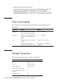
Text Conventions
This manual uses the following fonts and symbols to express specific types of
information.
Fonts/symbols
Meaning
Example
AaBbCc123
What you type, when contrasted
with on-screen computer output
# ls -l <Return>
AaBbCc123
The names of commands, files, and
directories; on-screen computer
output
# ls -l <Return>
Italic
Indicates the name of a reference
manual
See the XSCF User's Guide.
""
Indicates names of chapters,
sections, items, buttons, or menus
See Chapter 2, "Preparation for
Installation."
Prompt Notations
The following prompt notations are used in this manual.
xvi
Shell
Prompt Notations
XSCF
XSCF>
C shell
machine-name%
C shell super user
machine-name#
Bourne shell and Korn shell
$
Bourne shell and Korn shell
super user
#
OpenBoot PROM
ok
SPARC Enterprise M8000/M9000 Servers Overview Guide • April 2007
Syntax of the Command Line Interface
(CLI)
The command syntax is as follows:
■
■
■
■
■
A variable that requires input of a value must be enclosed in <>.
An optional element must be enclosed in [ ].
A group of options for an optional keyword must be enclosed in [ ] and delimited
by |.
A group of options for a mandatory keyword must be enclosed in {} and
delimited by |.
The command syntax is shown in a box.
Example:
XSCF> showuser -a
Environment Requirements for Using
This Product
This product is a computer that is intended to be used in a computer room.
Conventions for Alert Messages
This manual uses the following conventions to show alert messages, which are
intended to prevent injury to the user or bystanders as well as property damage, and
important messages that are useful to the user.
WARNING:
This indicates a hazardous situation that could result in death or serious personal
injury (potential hazard) if the user does not perform the procedure correctly.
Preface
xvii
CAUTION:
This indicates a hazardous situation that could result in minor or moderate personal
injury if the user does not perform the procedure correctly. This signal also indicates
that damage to the product or other property may occur if the user does not perform
the procedure correctly.
IMPORTANT:
This indicates information that could help the user to use the product more
effectively.
Alert Messages in the Text
An alert message in the text consists of a signal indicating an alert level followed by
an alert statement. Alert messages are indented to distinguish them from regular
text. Also, a space of one line precedes and follows an alert statement.
WARNING:
The tasks listed below for this product and optional product provided by Fujitsu
Siemens Computers should be performed only by authorized service personnel.
The user must not perform these tasks. Incorrect operation of these tasks may cause
electric shock, injury, or fire.
■
■
■
■
■
Installation and reinstallation of all components
Removal of front, rear, or side covers
Mounting/unmounting of optional internal devices
Connecting/disconnecting of external interface cables
Maintenance (repair and regular diagnosis and maintenance)
Also, important alert messages are shown in “Important Alert Messages” on
page xviii.
Notes on Safety
Important Alert Messages
This manual provides the following important alert signals:
xviii
SPARC Enterprise M8000/M9000 Servers Overview Guide • April 2007
Caution – The WARNING signal indicates a dangerous situation could result in
death or serious injury if the user does not perform the procedure correctly.
Task
Warning
Normal
operation
Electric shock, fire
Do not damage, break, or modify the power cables. Cable damage may
cause electric shock or fire.
Preface
xix
Caution – The CAUTION signal indicates a hazardous situation could result in
minor or moderate personal injury if the user does not perform the procedure
correctly. This signal also indicates that damage to the product or other property
may occur if the user does not perform the procedure correctly.
xx
Task
Warning
Normal
operation
Equipment damage
Be sure to follow the precautions below when installing the main unit.
Otherwise, the equipment may be damaged.
• Do not block ventilation slits.
• Avoid installing the equipment in a placed exposed to direct sunlight or
near equipment that becomes extremely hot.
• Avoid installing the equipment in a dusty place or a place directly
exposed to corrosive gas or salty air.
• Avoid installing the equipment in a placed exposed to strong vibration.
Also, install the equipment on a level surface so that it is stable.
• The grounding wire must be class 3 or higher. Connecting it with
another grounding wire for shared grounding may cause a malfunction.
Be sure to use a single grounding path for the grounding wire.
• Do not run any cable beneath any equipment. Also, prevent cables from
becoming taut. Never disconnect any power cable from the equipment
while power is being supplied to the equipment.
• Do not place anything on top of the main unit. Do not use the main unit
as a workspace.
• Avoid exposing the equipment to rapid changes in the ambient
temperature, such as a rapid increase during transport in winter. A
rapid increase in the ambient temperature causes moisture to condense
in the equipment. Use the equipment only after the difference between
its temperature and the ambient temperature is negligible.
• Avoid installing the equipment near a copy machine, air conditioner, or
welding machine, which is noisy.
• Take preventive action to minimize static electricity at the installation
location. Note that static electricity is easily generated in some carpets
and can cause the equipment to malfunction.
• Confirm that the power supply voltage and frequency during operation
match the rated values indicated on the equipment.
• Do not insert any object into an opening in the equipment. Components
inside the equipment use high voltage. Conductive foreign matter, such
as a metal object, inserted into the equipment, may cause a short circuit
between components, resulting in fire, electric shock, or equipment
damage.
• For maintenance of the equipment, contact your authorized service
personnel.
SPARC Enterprise M8000/M9000 Servers Overview Guide • April 2007
Task
Warning
Normal
operation
Data destruction
Confirm the items listed below before turning off the power. Otherwise,
data may be destroyed.
• All applications have completed processing.
• No user is using the equipment.
• When the main unit power is turned off, the Power LED on the
operation panel is turned off. Be sure to confirm that the Power LED is
off before turning off the main power (uninterruptible power supply
[UPS], power distribution box, main line switch, etc.).
If necessary, back up files before turning off the system power.
Data destruction
Do not forcibly stop a domain that is operating normally. Otherwise, data
may be destroyed.
Data destruction
Do not disconnect the power cable from the AC power input while power
is being supplied. Otherwise, data stored on hard disk units may be
destroyed.
Preface
xxi
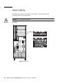
Alert Labels
The labels shown below are affixed on this product. These labels provide
information for users of the product:
Caution – Do not peel off the labels.
■
M8000
M8000 (Front View)
xxii
SPARC Enterprise M8000/M9000 Servers Overview Guide • April 2007
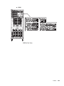
■
M9000
M9000 (Front View)
Preface
xxiii
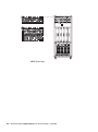
M9000 (Rear View)
xxiv
SPARC Enterprise M8000/M9000 Servers Overview Guide • April 2007
M9000 with Expansion Cabinet (Rear View)
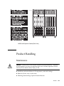
Product Handling
Maintenance
Caution – Certain tasks in this manual should only be performed by a certified
service engineer. User must not perform these tasks. Incorrect operation of these
tasks may cause electric shock, injury, or fire.
■
Installation and reinstallation of all components, and initial settings
■
Removal of front, rear, or side covers
■
Mounting/de-mounting of optional internal devices
Preface
xxv
■
Plugging or unplugging of external interface cards
■
Maintenance and inspections (repairing, and regular diagnosis and maintenance)
Caution – The following tasks regarding this product and the optional products
provided from Fujitsu Siemens Computers should only be performed by a certified
service engineer. Users must not perform these tasks. Incorrect operation of these
tasks may cause malfunction.
■
Unpacking optional adapters and such packages delivered to the users
■
Plugging or unplugging of external interface cards
Remodeling/Rebuilding
Caution – Any modification and/or recycling of this product and its components
may be carried out only by a certified service engineer and must not be done by the
customer under any circumstances.
Otherwise, electric shock, injury or fire may result.
Emission of Laser Beam (Invisible)
Caution – The main unit and high-speed optical interconnect cabinet contain
modules that generate invisible laser radiation.
Laser beams are generated while the equipment is operating, even if an optical cable
is disconnected or a cover is removed.
Do not look at any light-emitting part directly or through an optical apparatus (e.g.,
magnifying glass, microscope).
xxvi
SPARC Enterprise M8000/M9000 Servers Overview Guide • April 2007
Fujitsu Welcomes Your Comments
We would appreciate your comments and suggestions to improve this document.
You can submit your comments by using “Reader's Comment Form” on page xxviii.
Preface
xxvii
Reader's Comment Form
xxviii
SPARC Enterprise M8000/M9000 Servers Overview Guide • April 2007
FOLD AND TAPE
NO POSTAGE
NECESSARY
IF MAILED
IN THE
UNITED STATES
BUSINESS REPLY MAIL
FIRST-CLASS MAIL PERMIT NO 741 SUNNYVALE CA
POSTAGE WILL BE PAID BY ADDRESSEE
FUJITSU COMPUTER SYSTEMS
AT TENTION ENGINEERING OPS M/S 249
1250 EAST ARQUES AVENUE
P O BOX 3470
SUNNYVALE CA 94088-3470
FOLD AND TAPE
Preface
xxix
xxx
SPARC Enterprise M8000/M9000 Servers Overview Guide • April 2007
CHAPTER
1
System Overview
This chapter provides an overview of features, specifications, and configurations of
the SPARC® Enterprise M8000/M9000 Servers.
1.1
■
Product Overview
■
System Specifications
■
Server Components
■
Component Mounting Conditions
■
Optional Products
■
Software Features
Product Overview
SPARC Enterprise M8000/M9000 servers have been developed as UNIX servers
using a symmetric multi-processing (SMP) architecture. Each of these systems
merges mainframe technologies for high reliability, and the associated know-how
accumulated over time, with the high-speed technologies of super computers and
the openness of UNIX server development.
If a problem occurs during operation, the errors causing them can be corrected or
isolated without stopping the system. This feature minimizes problems in many
cases, thereby improving job continuity.
Each SPARC Enterprise M8000/M9000 Servers contains one or more SPARC64 VI
CPUs. They can operate as multiple servers that permit flexible use of resources,
including more efficient execution of job operations.
Each server consists of a cabinet containing various mounted components, a front
door, rear door, and side covers as parts of the server structure.
1-1
An operator panel is mounted on the front door and is always accessible. Take
special care in handling and storing the dedicated key is provided for the front door
and the operator panel.
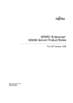
FIGURE 1-1 through FIGURE 1-3 show exterior views of the servers.
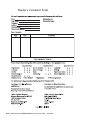
SPARC Enterprise M8000 Server Appearance
FIGURE 1-1
1-2
SPARC Enterprise M8000 Server
SPARC Enterprise M8000/M9000 Servers Overview Guide • April 2007
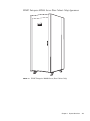
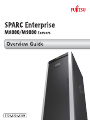
SPARC Enterprise M9000 Server (Base Cabinet Only) Appearance
FIGURE 1-2
SPARC Enterprise M9000 Server (Base Cabinet Only)
Chapter 1
System Overview
1-3
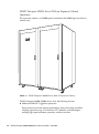
SPARC Enterprise M9000 Server (With an Expansion Cabinet)
Appearance
The expansion cabinet is an M9000 option connected to the M9000 (type for the base
cabinet only).
FIGURE 1-3
SPARC Enterprise M9000 Server (With an Expansion Cabinet)
SPARC Enterprise M8000/M9000 servers have the following features:
■
Multicore SPARC64 VI gigahertz processors
These processors provide superior performance, due to their high scalability
allowing expansion to up to 64 dual-core CPU modules, and technologies
enabling high-speed arithmetic operations and data transfers.
1-4
SPARC Enterprise M8000/M9000 Servers Overview Guide • April 2007
As faster and higher-performing CPU modules become available, they can be
added to or replace existing installed CPU modules to further improve
performance.
The system uses symmetric multiple-processing (SMP), so each CPU can access
any part of system memory regardless of its mounting location. Adding more
CPUs does not affect memory access to any of the installed CPUs.
■
High-speed crossbar-type system bus
The high-speed crossbar-type system bus provides high-speed wide-band data
transfer.
■
ECC memory
ECC functionality protects data on all system buses and in memory, so that any
errors in data are automatically corrected. In addition to ECC memory, Chipkill
memory protection is supported.
■
PCIe is mounted as I/O buses
PCIe, with a maximum bus width of eight lanes is used for the inter-connect bus
with the I/O device.
■
An optional External I/O Expansion Unit enables I/O slot expansion in the
system
Connect an External I/O Expansion Unit to add more PCIe and PCI-X slots to the
server.
An External I/O Expansion Unit is connected by a cable to a link card plugged
into a PCIe slot in an I/O unit.
■
The main components, power supply units, and FAN units can be configured to
be redundant
Redundant configurations can be used for the main components, such as a power
supply unit, FAN unit, hard disk unit, and PCI card. Implementation of
redundant configurations enables operation to continue without interruption
even if one of the units making up part of the system fails.
■
The main components, power supply units, and FAN units support active
replacement/addition
Component replacement and addition during system operation supported for the
main components, such as a power supply unit, FAN unit, hard disk unit, System
Control Facility (board), system board, and PCI card, with some exceptions.
Dynamic reconfiguration (DR) is used for active replacement and addition of
CMU and IOU configuring the system board.
PCI hot-plug (PHP) function enables replacement and addition of PCI Cards
while the system is running.
■
Automatic reboot on failure
Chapter 1
System Overview
1-5
If a failure occurs, the faulty component is automatically isolated from the system,
and the system is rebooted. If 1-bit errors occur frequently in the cache memory
configuring a CPU, the faulty memory can be dynamically isolated without
rebooting the Solaris Operating System. This type of graceful degradation
function enables the operation of the other resources to continue without
interruption, and also provides high fault-tolerance in case of failure.
■
eXtended System Control Facility (XSCF)
SPARC Enterprise M8000/M9000 servers use service processor called the
eXtended System Control Facility (XSCF), which monitors abnormalities in
hardware conditions, the operating status of domains, and system conditions
such as the temperature, power supply, and fan operation.
You can configure the system to selectively degrade a faulty component for
operation if an error is detected.
Scheduling is supported to enable automatic power-on and power-off of the
SPARC Enterprise system according to the specified operation schedule.
The console of each domain can be controlled from the XSCF via a network.
A browser-based user interface (BUI) and the command line interface (CLI)
facilitate operations for making configuration changes and status monitoring in
the system.
Note – A console display terminal is required for console control. Prepare it before
installation. The devices that can be used as the terminal are listed below.
■
■
■
■
PC
Workstation
ASCII terminal
Terminal server (or a touch panel connected to a terminal server)
Note – For the console connection method, see the SPARC Enterprise M8000/M9000
Servers Installation Guide.
■
Partitioning function
One high-end server can be divided into multiple areas, or domains, for more
effective scalability. Each domain manages resources in linkage with the XSCF. A
domain may consist of optimized resources depending on its intended use,
enabling more efficient system configurations.
Dynamic Reconfiguration (DR) enables adding, deleting, and relocating resources
of domains without stopping processing in the domain. This enables dynamic
reconfiguration of resources without stopping a job, even when the job load
increases suddenly or when a faulty component is replaced.
For details on domain functions, see the SPARC Enterprise
1-6
SPARC Enterprise M8000/M9000 Servers Overview Guide • April 2007
M4000/M5000/M8000/M9000 Servers Administration Guide.
For details of the DR function, see the SPARC Enterprise
M4000/M5000/M8000/M9000 Servers Dynamic Reconfiguration (DR) User’s Guide.
■
The SolarisTM Operating System (Solaris 10 or later) is supported.
With an added function for error prediction and self-recovery by the system
(Predictive Self-Healing) and enhanced process privilege management and
network functions, the Solaris Operating System sets new standards for
performance, efficiency, availability, and security.
■
Capacity on Demand (CoD)
Supports Capacity on Demand (CoD), which enables instantaneous increases in
the CPU capacity according to increases in the job load. Spare CPUs that are
mounted in advance can be used immediately upon purchase of a corresponding
number of CPU licenses, thereby accommodating such needs for increased
processing capacity.
For details, see the SPARC Enterprise M4000/M5000/M8000/M9000 Servers
Administration Guide.
1.2
System Specifications
This section lists specifications of both high-end servers, shows their appearance,
and provides an overview of the operator panel.
Chapter 1
System Overview
1-7
1.2.1
Main Unit Specifications
TABLE 1-1 to TABLE 1-4 list specifications of both high-end servers, installation
specifications, ambient conditions, and power conditions.
TABLE 1-1
Main Unit Specifications (1 of 2)
M9000
Item
M8000
Type
Floor-stand type 3
CPU
Main storage
(memory
module)
Base cabinet only
Base cabinet + expansion
cabinet
Type
SPARC64 VI
Number of
CPUs
32 cores (maximum 16
CPU modules)
64 cores (maximum 32
CPU modules)
128 cores (maximum 64
CPU modules)
Maximum
memory size
1 TB 4
2 TB 4
4 TB 4
Error
checking
function
Error Checking and Correction (ECC)
PCI slot built into SPARC
Enterprise (PCI Express) 1
Maximum 32 slots
Maximum 64 slots
Maximum 128 slots
External I/O Expansion Unit
(maximum number of
connections)
8 units (16 boats)
16 units (32 boats)
16 units (32 boats)
Maximum number of slots,
with I/O boats mounted
112 slots
224 slots
288 slots
Hard disk drive 2
16 slots
32 slots
64 slots
DVD-ROM drive
1 drive
2 drives
Tape drive
1 drive can be mounted (option)
2 drives can be mounted
(option)
Fan unit
4 units (type A)
8 units (type B)
16 units (type A)
32 units (type A)
Power supply unit
(Maximum number of
mounted units) (single phase,
one system)
9 units
15 units
30 units
Redundant configuration
Power supply unit, FAN unit, XSCF, power system (dual power feed option),
and clock supply system
Components that can be hotswapped
CPU/Memory board unit, I/O unit, System Control Facility, disk, PCI Card,
DVD-ROM drive, tape drive, External I/O Expansion Unit
1-8
SPARC Enterprise M8000/M9000 Servers Overview Guide • April 2007
TABLE 1-1
Main Unit Specifications (2 of 2)
M9000
M8000
System control interface
LAN, serial, uninterruptible power supply (UPS) interface, remote cabinet
interface (RCI), and USB 5
Number of domains
16
24
Solaris Operating System
6
Operating environment
Base cabinet only
Base cabinet + expansion
cabinet
Item
24
1 Up to eight lanes of PCIe bus are connected to each slot.
2 A built-in IOU Onboard Device Card_A (IOUA) is required for using hard disk drives.
3 The upper part of the SPARC Enterprise M8000 server cabinet has a 12 rack units (RU) space.
4 This is the maximum capacity when 8-GB dual inline memory modules (DIMM) are mounted.
5 This interface is only used for maintenance by authorized service personnel. It does not support general-purpose USB devices.
6 For the latest information on the operating system, visit our Web site, or contact your sales representative.
For up-to-date URL information, see the Web site information about the messages described in the reference
manuals noted in the Preface.
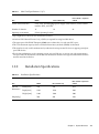
1.2.2
TABLE 1-2
Installation Specifications
Installation Specifications
M9000
M8000
Base cabinet only
Base cabinet + expansion
cabinet
Width [mm]
750
850
1674
Depth [mm]
1260
1260
1260
Height [mm]
1800
1800
1800
700
940
1880
Item
Outside
dimensions
Weight [kg]
Chapter 1
System Overview
1-9
1.2.3
TABLE 1-3
Environmental Specifications
Environmental Specifications
Humidity [%RH]1
Temperature [°C (°F)]
Server name
Operating
Non-operating
Operating
Non-operating
SPARC Enterprise
M8000 Server
5 to 32 (41 to 89.6) at an installation altitude
ranging from 0 to less than 1,500 m (4921
feet) above sea level
5 to 30 (41 to 86) at an installation altitude
ranging from 1500 m (4921 feet) to less than
2000 m (6562 feet) above sea level
5 to 28 (41 to 82.4) at an installation altitude
ranging from 2000 m (6562 feet) to less than
2500 m (8202 feet) above sea level
5 to 26 (41 to 78.8) at an installation altitude
ranging from 2500 m (8202 feet) to 3000 m
(9843 feet) above sea level
0 to 50
(32 to 122)
20 to 80
8 to 80
and
SPARC Enterprise
M9000 Server
1 Noncondensing.
1-10
SPARC Enterprise M8000/M9000 Servers Overview Guide • April 2007
1.2.4
Power Specifications
Two power input modes are available; single-phase power feed and three-phase
power input.
The following table lists power conditions for the single-phase power feed.
TABLE 1-4
Power Specifications
M9000
Item
Input power:
Single-phase
power input
M8000
Voltage [V]
AC200 to 240 ±10%
Frequency [Hz]
50/60 (+2% / -4%)
Base cabinet only
Base cabinet + expansion
cabinet
Power consumption [kW]
10.5 1
21.3 2
42.6 3
Apparent power [kW]
11.0 1
22.4 2
44.8 3
Power
conditions
Power Input
cable [m]
3.0
Plug shape
Japan: 30 A-250 V, 4P hook lock (The wiring between X and Y must be
single-phase 200-VAC wiring.)
North America: NEMA L6-30P
Europe: EN60309 (32A)
Number of plugs
3 (single power
feed)
6 (dual power
feed)
5 (single power feed)
10 (dual power feed)
10 (single power feed)
20 (dual power feed)
1 This value applies if 4 CPU/Memory Board Units and 4 I/O units are mounted.
2 This value applies if 8 CPU/Memory Board Units and 8 I/O units are mounted.
3 This value applies if 16 CPU/Memory Board Units and 16 I/O units are mounted.
To use a three-phase power source, a three-phase power feed option and a power
supply cabinet for mounting the option are required. The three-phase power feed
has two connection options: a star connection that connects a neutral line and each
phase, and a delta connection that connects each phase.
For details on specifications for the three-phase power feed, see the SPARC Enterprise
M8000/M9000 Servers Site Planning Guide.
Chapter 1
System Overview
1-11
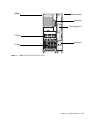
1.2.5
M8000 Server Components
FIGURE 1-4 shows the front of the SPARC Enterprise M8000 Server with a power
cabinet connected to it, and FIGURE 1-5 shows the server rear view. System
component names are shown in each figure.
The dual power feed option and three-phase power feed option can be mounted in
the power cabinet. One power cabinet is connected to the M8000.
19-inch Rack Space
Power Cabinet
Power Supply Unit
Power Supply Unit
DC-DC Converter
DC-DC Converter
XSCF Unit
CPU Memory Board Unit
Tape Drive Unit
DVD Drive Unit
CPU Memory Board Unit
AC Section
FIGURE 1-4
1-12
M8000 and Power Cabinet Front View
SPARC Enterprise M8000/M9000 Servers Overview Guide • April 2007
FAN Unit
M8000
Power Cabinet
AC Section
Power Supply Unit
FAN Unit
AC Section
I/O Unit
FIGURE 1-5
M8000 and Power Cabinet Rear View
Chapter 1
System Overview
1-13
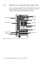
1.2.6
M9000 Server Components (Base Cabinet Only)
FIGURE 1-6 shows the front of the SPARC Enterprise M9000 Server (base cabinet only)
with a power cabinet connected to it, and FIGURE 1-7 shows the rear of the server.
The names of components of the system are shown in each figure.
One power cabinet is connected to the M9000 (base cabinet only).
Power Cabinet
FAN Unit
Power Supply Unit
AC Section
Power Supply Unit
Crossbar Unit
Clock Unit
XSFC Unit
I/O Unit
Tape Drive Unit
AC Section
FIGURE 1-6
1-14
M9000 (Base Cabinet Only) and Power Cabinet Front View
SPARC Enterprise M8000/M9000 Servers Overview Guide • April 2007
DVD Drive Unit
M9000
Power Cabinet
FAN Unit
CPU Memory Board Unit
I/O Unit
FIGURE 1-7
Power Supply Unit
AC Section
M9000 (Base Cabinet Only) and Power Cabinet Rear View
Chapter 1
System Overview
1-15
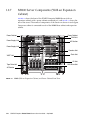
1.2.7
M9000 Server Components (With an Expansion
Cabinet)
FIGURE 1-8 shows the front of the SPARC Enterprise M9000 Server (with an
expansion cabinet) with a power cabinet connected to it, and FIGURE 1-9 shows the
rear of the server. The names of components of the Server are shown in each figure.
One power cabinet is connected to each of the M9000 base cabinet and expansion
cabinet.
Power Cabinet
Power Supply Unit
Power Cabinet
FAN Unit
AC Section
Power Supply Unit
Crossbar Unit
Clock Unit
XSCF Unit
I/O Unit
Tape Drive Unit
AC Section
FIGURE 1-8
1-16
M9000 (With an Expansion Cabinet) and Power Cabinet Front View
SPARC Enterprise M8000/M9000 Servers Overview Guide • April 2007
DVD Drive Unit
Power Cabinet
Power Cabinet
FAN Unit
Power Supply Unit
CPU Memory Board
Unit
CPU Memory Board
Unit
I/O Unit
I/O Unit
AC Section
Expansion Cabinet
FIGURE 1-9
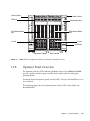
1.2.8
Base Cabinet
M9000 (With an Expansion Cabinet) and Power Cabinet Rear View
Operator Panel Overview
The operator panel has LEDs indicating different states of the M8000 and M9000
servers, a power switch for power control, and a mode switch for setting the
operation mode.
For details about the operator panel, see the SPARC Enterprise M8000/M9000 Servers
Service Manual.
The following figure shows the operator panel, and its LEDs and switches are
described below.
Chapter 1
System Overview
1-17
Operator Panel Appearance
FIGURE 1-10 shows the operator panel.
Locked
Service
POWER (LED)
O
(
FIGURE 1-10
STANDBY (LED)
CHECK (LED)
POWER switch
MODE switch
)
Operator Panel
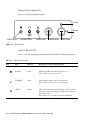
Operator Panel LEDs
TABLE 1-5 lists the operating states indicated by the LEDs on the operator panel.
TABLE 1-5
LEDs
1-18
Operator Panel LEDs
Name
Light color
Description of function and operating state
POWER
Green
Indicates whether the main unit power is on.
If this LED is on, the power is on.
STANDBY
Green
Indicates the standby state of the main unit.
If this LED is on, the power can be turned on.
CHECK
Amber
Indicates the main unit operating status. (This is used to
indicate a maintenance target, or it indicates that the unit
cannot be started.)
If this LED is on, a system error has been detected.
SPARC Enterprise M8000/M9000 Servers Overview Guide • April 2007
Operator Panel Switches
The switches on the operator panel include the mode switch for setting the operation
mode and the POWER switch for turning on and off the SPARC Enterprise Server.
To switch between system operation mode and maintenance mode, insert the
dedicated key of the high-end server and change the mode switch setting.
TABLE 1-6 lists functions of the switches on the operator panel.
TABLE 1-6
Switch
Operator Panel Switches
Name
Function
POWER switch
Controls the main unit power.
MODE switch
Selects between maintenance and normal operation. Use the
dedicated key managed by the customer to switch between
normal and maintenance modes.
Locked
This mode is set for normal operation.
Service
This mode is set for maintenance.
Chapter 1
System Overview
1-19
1.3
Server Components
This section describes the components of both high-end servers.
For details on each, see the SPARC Enterprise M8000/M9000 Servers Service Manual.
1.3.1
■
CPU Module
■
CPU/Memory Board Unit
■
I/O Unit
■
FAN Unit
■
Power Supply Unit
■
Crossbar Unit
■
Clock Control Unit
■
Operator Panel
■
XSCF Unit
■
Internal Drive Units
■
Hard Disk Drive
■
DVD-ROM Drive Unit/Tape Drive Unit
CPU Module
The CPU Module (CPUM) contains a SPARC64 VI CPU and a DC-DC converter
(DDC). Up to four CPU modules (CPUMs) can be mounted on a CPU/Memory unit.
The CPUM has the following features:
1-20
■
The CPUM contains a SPARC64 VI, a high-performance multicore CPU that uses
the latest LSI process.
■
If an unforeseen fault is detected, the SPARC64 VI CPU enables operation to
continue without interruption by using an automatic recovery function, automatic
retry function, or automatic degradation function, depending on how the system
is configured.
■
A redundant DDC configuration enables continuous operation even if a DDC
fails.
SPARC Enterprise M8000/M9000 Servers Overview Guide • April 2007
1.3.2
CPU/Memory Board Unit
The CPU/Memory Board Unit (CMU) contains CPUMs, memory modules, and a
DDC. The CMU and an I/O units can be combined to construct one or more
domains.
The CMU has the following features:
1.3.3
■
Contains an interconnect LSI module that uses the latest LSI process.
■
Uses Double Data Rate (DDR)II DIMM memory.
■
Supports the DR function that enables hot maintenance and replacement of CMUs
during system operation, and enables addition and deletion of active CMUs
during system operation.
■
A redundant DDC configuration enables continuous operation even if a DDC
fails.
I/O Unit
The I/O unit (IOU) consists of a PCIe bridge control LSI module, a printed circuit
board containing a DDC, a hard disk drive (HDD), PCIe slots, and PCI cassettes for
the IOU. The IOU and the CMU can be combined to configure a server.
The IOU has the following features:
■
It contains eight PCIe slots.
■
The IOU Onboard Device Card_A (IOUA) can be used to connect the in-cabinet
disk drive (2.5-inch SAS interface), the in-cabinet DVD-ROM drive, and a tape
device. The LAN port (1000BASE-T/100Base-TX/100Base-T) mounted on the card
can be used.
■
It supports PCI hot-plug for External I/O Expansion Units and PCIe slots.
■
An External I/O Expansion Unit can be used to connect the IOU to an External
I/O Expansion Unit connection card.
■
Supports the DR function that enables active maintenance and replacement of
IOUs during system operation and enables addition and deletion of active IOUs
during system operation.
■
Insert the PCI Card into one of the supplied cassettes before inserting it into a
built-in PCIe slot in the IOU. A PCI card whose length is up to 177.8 mm (short
size) can be mounted in a slot.
■
A redundant DDC configuration enables continuous operation even if a DDC
fails.
Chapter 1
System Overview
1-21
1.3.4
FAN Unit
The FAN unit is used to cool the server. There are two types of FAN units, with the
following features:
1.3.5
■
A redundant fan configuration enables continuous system operation even if a fan
fails during system operation.
■
Hot system maintenance or replacement of a faulty fan can be performed during
system operation.
Power Supply Unit
The power supply unit (PSU) feeds power to each unit, and has the following
features:
1.3.6
■
A redundant configuration enables the system operation to continue without
interruption even if a power supply unit fails during system operation.
■
Hot system maintenance or replacement of a faulty power supply unit can be
performed during system operation.
Crossbar Unit
The crossbar unit (XBU) consists of crossbar switches that logically connect CMUs
and IOUs.
The XBU has redundant bus routes. If one route fails, the system can be restarted
through the other route to continue operation.
1.3.7
Clock Control Unit
The clock control unit (CLKU) contains an LSI module used for the clock.
The CLKU has redundant clock supply routes. If one route fails, the system can be
restarted through the other route to continue operation.
1.3.8
Operator Panel
The operator panel can be used to turn on and off the server power, switch between
operation modes, and display system status information.
1-22
SPARC Enterprise M8000/M9000 Servers Overview Guide • April 2007
The operations of switches on the operator panel can be limited by switching the
operation mode with the dedicated key supplied for the panel.
1.3.9
XSCF Unit
The XSCF unit (XSCFU) includes a dedicated processor, which operates
independently from the main unit processors. The XSCFU in the servers adopts a
duplicated configuration to increase fault tolerance.
The XSCFU is equipped with hardware interfaces for network connections to remote
devices such as personal computers and workstations. A remote device can be
connected via a network to the XSCF to control startup, settings, and operation
management of the system.
The XSCFU provides the following hardware interfaces for network connections:
■
Serial port
■
LAN ports (10/100BASE-T/100Base-TX)
The XSCF can be accessed through network connections using these interfaces. The
commandline interface (XSCF shell) and browser-based user interface (XSCF Web
pages) provided by the XSCF enable operation and management of the servers.
For details, see the SPARC Enterprise M4000/M5000/M8000/M9000 Servers XSCF
User’s Guide.
1.3.10
Internal Drive Units
The SPARC Enterprise M8000/M9000 servers contain the following in-cabinet drive
units. These allow active replacement or addition:
Hard Disk Drive
The hard disk drive is a 2.5-inch hard disk drive with a serial attached SCSI (SAS)
interface. It can be mounted in an IOU.
Chapter 1
System Overview
1-23
DVD-ROM Drive Unit/Tape Drive Unit
The DVD drive cannot be directly shared by multiple domains in a server. However,
if the multiple domains are connected to one another through a LAN and a certain
function of the Solaris Operating System is used, the DVD drive can be shared by
the domains. Adequate consideration of security is necessary for LAN connections
between domains.
1.4
Component Mounting Conditions
1.5
■
CPUMs can be added in units of two modules.
■
Dual inline memory module (DIMMs) can be added in units of 16 modules.
■
If you add an IOU, a CMU must be mounted for the slot with the same slot
number.
■
IOU Onboard Device Card_A (IOUA) can be mounted in PCIe Slot #0, #2, #4, and
#6 in the IOU.
■
External I/O Expansion Unit connection cards can be mounted in PCIe Slot #1, #3,
#5, and #7 in the IOU.
Optional Products
The following products are the main options available for the SPARC Enterprise
M8000/M9000 Servers.
■
Power Supply Options
■
External I/O Expansion Unit
■
SPARC Enterprise M9000 Server (Expansion Cabinet) Option
For information about other optional products, visit our web site.
1.5.1
Power Supply Options
The power cabinet and the rack-mountable dual power feed option for the SPARC
Enterprise M8000 server are offered as power supply options.
The power cabinet enables dual power feed or three-phase power feed.
1-24
SPARC Enterprise M8000/M9000 Servers Overview Guide • April 2007
The rack-mountable dual power feed option for the SPARC Enterprise M8000 server
receives power from two external AC power sources that are independent of each
other, and duplicates the input power system.
To use a single-phase dual power feed configuration for the SPARC Enterprise
M8000 server, mount the rack-mountable dual power feed option in the rack space
itself. This requires a rack space with a height of 6 RUs in the cabinet. For the SPARC
Enterprise M9000 server, you must add the power cabinet.
For three-phase power feed in either server, an additional power cabinet is required.
Install one power cabinet for each SPARC Enterprise M8000/M9000 Server.
For details, see the SPARC Enterprise M8000/M9000 Servers Site Planning Guide.
Note – A three-phase power feed option can be installed only at the factory before
shipment. A single-phase power feed cannot be changed to a three-phase power
feed, or vice versa, after shipment from the factory.
TABLE 1-7 lists specifications of the power cabinet.
TABLE 1-7
Specifications of the Power Cabinet and M8000/M9000 Dual Power Feed Option
Rack-mountable Dual
Power Feed options
Item
Outside dimensions
Width [mm]
Depth [mm]
Height [mm]
Weight [kg]
Input power:
Single-phase power
input
Voltage [V]
Number of phases
Frequency [Hz]
Power Cabinet
489
1003
278(6U)
317
1244
75
350
1800
AC200 to 240 ± 10%
Single phase
50/60 +2%, -4%
Note – For specifications of the three-phase power feed option, see the SPARC
Enterprise M8000/M9000 Servers Site Planning Guide.
Chapter 1
System Overview
1-25
1.5.2
External I/O Expansion Unit
The External I/O Expansion Unit is an optional product used to add PCI slots. The
External I/O Expansion Unit has a height of four RUs (rack units), about 18 cm, in a
19-inch rack.
The External I/O Expansion Unit can accommodate up to two I/O Boats by using
either six PCIe slots or six PCI-X slots.
■
PCIe slots in each I/O Boat: short size to long size (to 312 mm)
■
PCI-X slots in each I/O Boat: short size to long size (to 312 mm)
Also, active addition and replacement is enabled for all slots in the External I/O
Expansion Unit.
For details, see the I/OExpansion Box Installation and Service Manual .
FIGURE 1-11 shows the External I/O Expansion Unit.
FIGURE 1-11
1.5.3
External I/O Expansion Unit
SPARC Enterprise M9000 Server (Expansion
Cabinet) Option
A SPARC Enterprise M9000 Server (base cabinet) configuration can contain up to 32
CPU Modules (64 cores), up to 2TB of memory, and up to 224 PCI slots. A
configuration containing more components than described above would require the
expansion cabinet option of the SPARC Enterprise M9000 Server.
A configuration with the SPARC Enterprise M9000 Server (expansion cabinet) can
contain up to 64 CPU modules (128 cores), up to 4TB of memory, and up to 288 PCI
slots.
1-26
SPARC Enterprise M8000/M9000 Servers Overview Guide • April 2007
For information about connecting the SPARC Enterprise M9000 Server (expansion
cabinet) and the SPARC Enterprise M9000 Server (base cabinet), see the SPARC
Enterprise M8000/M9000 Servers Installation Guide.
1.6
Software Features
The SPARC Enterprise M8000/M9000 Servers use XSCF for system administration
and monitoring.
The Solaris Operating System can be installed as the operating environment used in
a domain.
For details, see Chapter 3.
Chapter 1
System Overview
1-27
1-28
SPARC Enterprise M8000/M9000 Servers Overview Guide • April 2007
CHAPTER
2
System Features
This chapter explains the following technical aspects, including features and
structures.
2.1
■
Hardware Configuration
■
Partitioning
■
Resource Management
■
RAS
Hardware Configuration
This section explains the hardware configuration, which includes the following
items:
2.1.1
■
CPU
■
Memory Subsystem
■
I/O Subsystem
■
System Bus
■
System Control
CPU
The SPARC Enterprise M8000/M9000 Servers use the SPARC64 VI CPU, a
proprietary high-performance multi-core processor. On-chip L2 cache memory
minimizes memory latency.
An instruction retry function has been implemented so that operation can be
continued by retrying an instruction for which an error has been detected.
2-1
The SPARC Enterprise M8000 server, SPARC Enterprise M9000 server, and the
SPARC Enterprise M9000 server with expansion cabinet take advantage of system
scalability by supporting up to 16, 32, or up to 64 CPU modules, respectively.
CPU modules running at different clock frequencies can be used in a single system.
The latest CPUs can therefore be installed when improved processing performance is
required.
2.1.2
Memory Subsystem
The memory subsystem controls memory access and cache memory. The server uses
DDR-II DIMM memory.
Each CMU has thirty-two memory slots.
Also, the SPARC Enterprise M8000 server, SPARC Enterprise M9000 server, and
SPARC Enterprise M9000 server with expansion cabinet can mount up to 128, 256, or
512 DIMMs, respectively.
The memory subsystems use up to eight-way interleaving, providing higher-speed
memory access.
Memory mirror mode is supported for every pair of memory buses in a CMU. This
enables continued operation using the other non-defective bus if an error occurs in
one bus. Memory mirror mode can be set up by the system administrator.
2.1.3
I/O Subsystem
The I/O subsystem controls data transfer between the main unit and I/O devices.
These servers use PCIe as the interconnect bus for I/O devices.
Each IOU contains eight-lane (x8) PCIe slots. Also, eight-lane PCIe slots or 133-MHz
64-bit PCI-X slots can be in a mounted through an External I/O Expansion Unit.
The SPARC Enterprise M8000 server, SPARC Enterprise M9000 server, and the
SPARC Enterprise M9000 with expansion cabinet can mount up to 32, 64, or 128
PCIe-compatible cards, respectively.
PCI-Express slots or PCI-X slots can be added by mounting an External I/O
Expansion Unit through a PCI-Express slot.
2-2
SPARC Enterprise M8000/M9000 Servers Overview Guide • April 2007
2.1.4
System Bus
The CMU containing a CPU and memory subsystem and each component in an IOU
containing an I/O subsystem are used for high-throughput data transfer between all
components through a crossbar switch. The crossbar switch has duplicated bus
routes. If one crossbar switch has an error, the system can be restarted to isolate the
faulty switch, enabling the high-end servers to continue operation.
FIGURE 2-1 shows data transfer in the system.
Chapter 2
System Features
2-3
FIGURE 2-1
2-4
Main Component Connections
SPARC Enterprise M8000/M9000 Servers Overview Guide • April 2007
Note – The SC is the system controller that controls CPUs and memory and handles
communication with the XB.
2.1.5
System Control
System control of this server refers to the system control contained within the
XSCFU that runs the XSCF and every component controlled by the XSCF.
As long as input power is being supplied to the server, the XSCF constantly
monitors the server even if all domains are powered off.
The following functions are provided to increase system availability:
■
■
■
■
■
■
■
■
■
2.2
Configuration management and monitoring
Cooling unit (FAN) monitoring
Domain status monitoring
Power-on and power-off of peripheral devices1
Complete control and monitoring of the server through abnormality monitoring
Remote partitioning for domain configuration and management
Server management and monitoring functions by the user through an external
network connection
Notifying the system administrator of fault information on the server
Remote console input-output
Partitioning
A single SPARC Enterprise M8000/M9000 server cabinet can be divided into
multiple independent systems for operation. This dividing function is called
partitioning.
This section describes features of partitioning and system configurations that can be
implemented through partitioning.
1. The connected device must have the same interface to be effective.
Chapter 2
System Features
2-5
2.2.1
Features
The individual systems resulting from partitioning can be built in the SPARC
Enterprise M8000/M9000 Servers. These individual, divided systems are called
domains. Domains are sometimes called partitions.
Partitioning enables arbitrary assignment of resources in the server. Partitioning also
enables flexible domain configurations to be used according to the job load or
processing amount.
An independent operating system can run in a domain. Each domain is protected by
hardware so that it is not affected by other domains. For example, a software-based
problem, such as an OS panic, in one domain does not directly affect jobs in the
other domains. Furthermore, the operating system in each domain can be reset and
shut down independently.
2.2.2
Domain Hardware Requirements
The basic hardware resources making up a domain are a CMU and IOU mounted in
the high-end servers or a physical system board (PSB) consisting of a CMU.
A PSB can be logically divided into one part (no division) or four parts. The physical
unit configuration of each divided part of a PSB is called an extended system board
(XSB).
A PSB that is logically divided into one part (no division) is called a Uni-XSB, and a
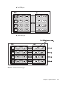
PSB that is logically divided into four parts is called a Quad-XSB.
A domain can be configured with any combination of these XSBs. The XSCF is used
to configure a domain and specify the PSB division type.
FIGURE 2-2 shows the partitioning division types.
2-6
SPARC Enterprise M8000/M9000 Servers Overview Guide • April 2007
FIGURE 2-2
■
Uni-XSB types
■
Quad-XSB types
Partition Division Types
Chapter 2
System Features
2-7
2.2.3
Domain Configuration
Any XSBs in the server can be combined to configure a domain, regardless of
whether the divided XSB is the Uni-XSBs or Quad-XSBs.
These XSBs can be used in any combination for a flexible domain configuration.
Also, the quantity of resources for one XSB can be adjusted according to the division
type of a PSB. Thus, a domain can be configured based on the quantity of resources
required for job operations.
XSCF user interfaces are used to configure a domain. Each configured domain is
managed by the XSCF.
The maximum number of domains that can be configured in the servers depends on
the system. Up to 16 domains can be configured in SPARC Enterprise M8000 servers,
and up to 24 domains can be configured in SPARC Enterprise M9000 servers.
To configure a domain, an LSB number must first be assigned so that a logical
system board (LSB) can function as an LSB of the XSB.
This LSB number is referenced by the Solaris Operating System, and it must be a
unique number in the domain. However, if one XSB is shared by multiple domains,
a common LSB number need not be defined in the domains. An arbitrary LSB
number can be assigned for this setting in each domain.
Domain configuration settings are made for each domain. A domain can be
configured by specifying an XSB together with this LSB number.
Up to 16 XSBs can be configured in a single domain.
The following as well as the quantity of resources must be considered by the user
who is specifying the domain configuration and division type:
■
The Uni-XSB type is suitable in the configuration of a domain requiring a large
quantity of resources. Also, an XSB of the Uni-XSB type is separated by the
physical configuration units of a CMU and IOU. Thus, if a hardware error occurs
in a CPU or memory, hardware can easily be replaced without affecting other
domains. However, a resource quantity decrease due to an error may be in the
range specified by the PSB.
■
Quad-XSB type is suitable in the configuration of a small-scale domain, and
optimized for flexible resource management. However, since domains are
logically separated in a PSB, an error in the hardware shared within the PSB may
affect other domains.
In addition, resources of a configured domain can be added to and deleted from
individual XSBs, and they can be moved between domains.
2-8
SPARC Enterprise M8000/M9000 Servers Overview Guide • April 2007
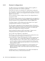
FIGURE 2-3 shows the domain configuration.
FIGURE 2-3
Domain Configuration
Chapter 2
System Features
2-9
2.3
Resource Management
This section explains the following functions that support dynamic reconfiguration
of domain resources during system operation:
2.3.1
■
Dynamic Reconfiguration
■
PCI Hot-plug
■
Capacity on Demand
■
Zones
Dynamic Reconfiguration
Dynamic reconfiguration (DR) enables hardware resources on system boards to be
added and removed dynamically without stopping system operation. DR thus
enables optimal relocation of system resources. Also, if a failure occurs, DR can place
the system in a state that enables active replacement of the faulty component.
Using the DR function enables additions or distributions of resources as required for
job expansions or new jobs, and it can be used for the following purposes.
■
Effective use of system resources
By reserving some resources, the reserved resources can be added according to
changes in the work load occurring daily, monthly, or annually. This enables
flexible resource allocations on the system that needs to operate 24 hours a day,
every day of the year in accordance with changes in the amount of data and the
work load.
■
Active replacement of system resources
If a failure occurs in a CPU for a domain that has been configured with system
resources of multiple system boards, the DR function enables the faulty CPU to be
isolated dynamically without stopping the system. The replacement CPU can be
configured dynamically in the original domain.
For details on Dynamic Reconfiguration, see the SPARC Enterprise
M4000/M5000/M8000/M9000 Servers Dynamic Reconfiguration (DR) User’s Guide.
2-10
SPARC Enterprise M8000/M9000 Servers Overview Guide • April 2007
2.3.2
PCI Hot-plug
The PCI hot-plug function enables PCI cards to be added or removed under the
Solaris Operating System without a system reboot.
Examples of uses for the PCI hot-plug function are as follows:
■
Replacing or removing a faulty PCI card or one that will probably become faulty,
during system operation
■
Adding a PCI card during system operation
For details on the PCI hot-plug function, see the SPARC Enterprise M8000/M9000
Servers Service Manual.
2.3.3
Capacity on Demand
Capacity on Demand (COD) is an optional service that allows the user to purchase
spare processing resources (CPUs) for the servers. The spare resources are provided
in the form of one or more CPUs on COD boards that are installed on your server.
However, to access these CPUs, you must first purchase the COD right-to-use (RTU)
licenses for them.
Note – RTU means a license applicable to each CPU. To use CPUs with the extra
number of CPU RTUs purchased beforehand, the user needs to purchase additional
RTUs processors on each system board. The right-to-use license for CPUs specifies
the number of CPUs that can be used in the entire system. The system administrator
decides the system boards and domains to which the Right to Use is to be assigned.
The right-to-use license for CPUs specifies the number of CPUs that can be used in
the entire system. The system administrator decides the system boards and domains
to which the Right to Use is to be assigned.
For details on RTU assignment, see Section 3.2.2.6, “Resource Management” on
page 3-5.
For details on COD, see the SPARC Enterprise M4000/M5000/M8000/M9000 Servers
Administration Guide.
2.3.4
Zones
The Solaris 10 OS has a function called Zones that divides the processing resources
and allocates them to applications.
Chapter 2
System Features
2-11
In a domain, resources can be divided into sections called containers, and the
processing sections are allocated to each application. The processing resources are
managed independently in each container. If a problem occurs in a container, the
container can be isolated so that it does not affect other containers. It provides
flexible resource allocation that enables optimal resource management with
consideration given to the processing load.
2.4
RAS
RAS is an acronym for functions related to Reliability, Availability, and
Serviceability.
RAS for SPARC Enterprise M8000/M9000 servers minimizes system downtime by
providing for error checking at appropriate locations and by providing centralized
monitoring and control of error checking.
Also SPARC Enterprise M8000/M9000 servers can be configured with clustering
software or centralized management software to enhance the RAS function.
Any scheduled system halt, such as a periodic maintenance or system configuration
change can also be performed without affecting operating resources. This can
improve service uptime significantly.
2.4.1
Reliability
To improve quality and gain high reliability, you must select appropriate
components considering the lifetime of the products and response at the time of
error occurrence.
Reliability is equally important to both hardware and software.
Furthermore, software errors are not only triggered by program errors, but also by
hardware errors.
SPARC Enterprise M8000/M9000 servers provide the following functions to realize
high reliability.
2-12
■
Monitoring by the XSCF to periodically check whether software such as the
Solaris Operating System is running in domains (host watchdog monitoring).
■
Memory patrol is periodically performed to detect memory software errors and
stuck faults, even in memory areas not normally used, to prevent use of faulty
memory and thereby prevent system failures caused by faulty memory from
occurring.
SPARC Enterprise M8000/M9000 Servers Overview Guide • April 2007
■
2.4.2
Since ECC protects functional data in all routes including a computing unit, a
register, cache memory, and a system bus, all 1-bit errors can be automatically
corrected by hardware to ensure data integrity.
Availability
Availability is characterized by how easily a server fails and how quickly the user
can be recovered from the failure. The amount of time the system is usable is
represented as a percentage.
Hardware and software faults in the system cannot be completely eliminated. To
provide high availability, the system must include mechanisms that enable
continuous system operation even if a failure occurs in hardware, such as
components and devices, or in software, such as the operating system, or application
software.
SPARC Enterprise M8000/M9000 servers provide the functions listed below to
obtain high availability. Higher availability can also be obtained by combining the
server with clustering software or management software.
■
Supporting redundant configurations and hot replacement of power supplies and
fans
■
Supporting redundant configuration of disks, mirroring by software and active
replacement
■
Extended range of automatic correction of temporary faults in memory, system
buses, and LSI internal data
■
Support of an enhanced retry function and degradation function for detected
faults
■
Shortening the downtime by using automatic system reboot
■
Shortening the time taken for system startup
■
XSCF collection of fault information, and preventive maintenance using different
types of warnings
■
Supporting the Chipkill function in the memory subsystem, which enables singlebit error correction to continue processing in response to continuous burst read
errors caused by failures of a memory device
■
Supporting the memory mirroring function enables normal data processing
through the other memory bus, thereby preventing system failures in response to
an error at the bus or device connected to memory bus
■
Memory patrol function has no influence on the workload of software operation
because it is implemented in hardware
Chapter 2
System Features
2-13
2.4.3
Serviceability
Serviceability is characterized by how easily a server fault can be diagnosed, and
how quickly the server can be recovered from the fault or how easily the fault can be
corrected.
To achieve high serviceability rates, it must be possible to identify the causes of
component or device failure. To facilitate recovery from failure, the system must
determine the cause of the failure and isolate the faulty component for replacement.
The system must also notify the system administrator and/or field engineer of the
event and situation in an easy-to-understand format that prevents
misunderstandings.
SPARC Enterprise M8000/M9000 servers provide the following solution to realize
high serviceability:
2-14
■
Status LEDs mounted on the operator panel, indicating the main replaceable
components and the components to which active replacement is applicable
■
Remote recognition of the device operating status and remote maintenance using
the XSC
■
LED blinking function for indicating the maintenance target (CHECK-LED, which
is also called a locator)
■
Notes and cautions marked on different types of labels provided for the system
administrator and field engineers
■
Automatic notification for reporting different types of faults to the system
administrator and field engineers
■
Centralized systematic monitoring, such as supporting SNMP, of a complex
system from a data center
SPARC Enterprise M8000/M9000 Servers Overview Guide • April 2007
CHAPTER
3
About Software
This chapter explains the following software functions.
3.1
■
Solaris Operating System Functions
■
XSCF Firmware Function
Solaris Operating System Functions
The Solaris Operating System (Solaris OS) has the following features:
■
Solaris reliability that has been built over the years
■
Affinity that fully brings out the hardware performance of the SPARC
architecture.
■
A variety of products from ISVs (application software and middleware)
■
Resource optimization using the partitioning and DR functions
■
Dynamic addition/change of IO device using PCI hot plug
■
Resource management with Solaris zones using Solaris container technology
■
Advanced system management in cooperation with XSCF
For details of the Solaris Operating System, see the manual on the following URL.
http://docs.sun.com
Irrespective of the capabilities of the software suite, the Solaris Operating System has
the following functions for communicating with the SPARC Enterprise server
hardware:
■
Domain Management
■
PCI Hot-plug
3-1
3.1.1
Domain Management
In the SPARC Enterprise M8000/M9000 Servers servers, a physical system board
(PSB) can be logically divided into one part (no division) or four parts by a
partitioning function unique to the system.
A PSB that is logically divided into one part (no division) is called a Uni-XSB, and a
PSB that is logically divided into four parts is called a Quad-XSB.
The physical unit configuration of each divided part of a PSB is called an extended
system board (XSB).
In the SPARC Enterprise system, a domain can be configured with any combination
of these XSBs.
3.1.2
PCI Hot-plug
SPARC Enterprise M8000/M9000 servers support insertion and removal of PCI cards
for specific PCI-Express and PCI-X hot-plug controllers. Before removing the PCI
card, be sure to cancel the settings and isolate the card by using the Solaris OS
cfgadm(1M) command, and make sure that the card is physically removable.
For details of PCI hot-plug, see the SPARC Enterprise M4000/M5000/M8000/M9000
Servers Administration Guide.
3.2
XSCF Firmware Function
The XSCF firmware is a System Control Facility including a dedicated processor that
is independent from the processors in the server. This section describes XSCF
firmware features and provides an overview of XSCF firmware functions.
3.2.1
XSCF Features
The XSCF is firmware that is preinstalled, and operates on the XSCFU as standard
equipment. As long as input power is being supplied to the server, the XSCF
constantly monitors and manages the server even if the power to domains is turned
off. In addition, the XSCF provides a user interface from which users can operate
and manage the server.
3-2
SPARC Enterprise M8000/M9000 Servers Overview Guide • April 2007
The XSCFU has a serial port and LAN port as external interfaces. A terminal such as
a personal computer or workstation can be connected to the XSCF through a serial
connection or Ethernet connection.
The servers can be operated and managed from the command line-based XSCF shell
or browser-based XSCF Web pages provided by the XSCF.
Only the XSCF shell can be used through the serial connection. Both the XSCF shell
and XSCF Web pages can be used through the Ethernet connection.
Note – The XSCFU supports a redundant configuration (duplicate configuration) for
high reliability.
The XSCF that is currently in control of the server is called the active XSCFU, and
the other XSCF is called the standby XSCF or standby XSCFU since it serves as the
backup XSCF to the active one.
The active XSCF and standby XSCF monitor each other to implement a failover
mechanism to switch between the active XSCF or standby XSCF when one of them
detects and error in the other.
For details on functions provided by the XSCF, see Section 3.2.2, “XSCF Functional
Overview” on page 3-4, and the SPARC Enterprise M4000/M5000/M8000/M9000
Servers eXtended System Control Facility (XSCF) User’s Guide.
3.2.1.1
Command Line-based User Interface (XSCF shell)
The XSCF shell is a command line-based user interface that can be used from a
terminal, such as a personal computer or workstation, connected to the XSCF
through a serial connection or Ethernet connection.
With the serial connection, the terminal is connected directly to the server to use
shell commands provided by the XSCF. Also, the console redirection function of the
XSCF enables the terminal to be used as an operating system console.
With the Ethernet connection, the terminal is connected to the XSCF via Secure Shell
(SHH) or telnet to use shell commands provided by the XSCF.
The following are the main operations that can be performed with the XSCF shell:
■
Display the server configuration or status and various related settings
■
Display the domain configuration or status and various related settings
■
Start or shut down a domain
■
Make settings for various network services
■
Make settings for various security functions
Chapter 3
About Software
3-3
■
3.2.1.2
Make various settings for the remote maintenance service function
Browser-Based User Interface (XSCF Web)
XSCF WEb is a browser-based user interface that can be used from a terminal, such
as a personal computer or workstation, connected to the server through an Ethernet
connection.
However, the XSCF Web pages cannot be used through a serial connection. If the
browser function of a terminal is used for a connection to the XSCF, BUI operations
can be performed.
3.2.2
XSCF Functional Overview
This section provides an overview of the main functions supported by the XSCF.
For details on each function, see the SPARC Enterprise M4000/M5000/M8000/M9000
Servers eXtended System Control Facility (XSCF) User’s Guide.
3.2.2.1
System Management
The main tasks of the XSCF are control and monitoring of the entire SPARC
Enterprise system, such as configuration management and monitoring of the
server’s cooling components (FAN units), domain status monitoring, power-on and
power-off of peripheral units, and error monitoring. Also, the XSCF provides a
partitioning function for domain configuration and management.
The XSCF constantly monitors the server status so that the system can operate stably.
When any error is detected in the system, the system status monitoring mechanism
immediately collects error information about the hardware (hardware log) and
analyzes it to identify the error location and check the error status. The XSCF
displays the status, and it degrades the relevant component or domain as necessary
or it resets the system, thereby preventing the error from occurring again.
The XSCF provides high reliability, high availability, and high serviceability for the
entire system.
3.2.2.2
Security Management
The XSCF manages user accounts for the XSCF. The operating range in the XSCF
shell and XSCF Web pages can be limited based on user account types and settings.
Moreover, the XSCF provides an IP address filtering function for permitting access to
3-4
SPARC Enterprise M8000/M9000 Servers Overview Guide • April 2007
the XSCF and an encryption function using SSH and SSL. Operator errors and
unauthorized access during system operation are recorded in a log. The system
administrator can use these functions to investigate the cause of a system problem.
3.2.2.3
System Status Management
The XSCF provides functions as XSCF operations for displaying the system
configuration status, creating and changing a domain configuration definition, and
starting and stopping domains. Also, the XSCF provides the DR function, which
assists in dynamically changing a system board configuration during domain
operation. Thus, domain resources can be optimized for job operations. Moreover,
the XSCF in linkage with the Solaris Operating System manages CPU, memory, and
I/O resources.
3.2.2.4
Error Detection and Management
The XSCF constantly monitors the system status so that the system can operate
stably. When any error is detected in the system, the XSCF immediately collects error
information about the hardware (hardware log) and analyzes it to identify the error
location. To continue operation, the XSCF degrades the relevant component or
domain as necessary according to error conditions or it resets the system, thereby
preventing the problem from occurring again. The user can take prompt action for
problems since easy-to-understand and accurate information on hardware errors and
fault locations are thus provided to the user.
3.2.2.5
Remote System Control and Monitoring
The XSCF provides functions for monitoring the server through an Ethernet
connection so that the user can remotely manage the server. Moreover, a function for
reporting error information to the system administrator and a remote console inputoutput function are supported. System availability is thus increased.
3.2.2.6
Resource Management
XSCF manages hardware resources on configured domains and system boards. As
for the resource management, DR function that enables dynamic reconfiguration of
domains is provided. Moreover, COD is provided to realize resource management
CPUs that is purchased by license.
Chapter 3
About Software
3-5
Dynamic Reconfiguration (DR)
The XSCF assists in dynamically changing a system board configuration during
system operation. The XSCF can be used for dynamic reconfiguration of domains.
For details on DR, see the SPARC Enterprise M8000/M9000 Servers Service Manual.
Capacity on Demand (COD)
To use CoD, RTUs must be purchased. Then, resources such as CPUs must be
configured according to the number of purchased RTUs so that they can be used as
needed. The licenses that are defined are allocated to individual resources when
such resources are required for use because of the start of a domain or another
trigger.
For details, see the SPARC Enterprise M4000/M5000/M8000/M9000 Servers
Administration Guide.
3-6
SPARC Enterprise M8000/M9000 Servers Overview Guide • April 2007
Glossary
B
BUI
Browser-based user interface.
C
Capacity on Demand
(COD)
CLI
clock control unit
(CLKU)
CLKU
CPU
CPU/Memory Board
unit
(CMU)
CPUM
An option that provides additional CPU processing resources when needed.
These additional CPUs are provided on COD CPU boards that are installed in
the server. To access the COD CPUs, you must purchase the COD right-to use
(RTU) licenses for them.
Command-line interface.
Unit consisting of the clock board and mechanical components. This is an
active replaceable unit.
See clock control unit (CLKU).
Central processing unit.
In the SPARC Enterprise M8000/M9000 servers the CPU/Memory unit consists
of the CPU, memory and CMU channel.
See CPU module (CPUM).
Glossary-1
CPU module
(CPUM)
crossbar (XB)
Crossbar unit (XBU)
A module containing one or two CPU chip(s).
The switch ASIC that controls the transfer of data between the System
Controller (SC) and the I/O.
The board that mounts the crossbar large-scale integration (XB ASICs). The
crossbar unit is used in the SPARC Enterprise M9000 model. In the SPARC
Enterprise M9000 with Expansion Cabinet model, the cable among crossbar
units connect each chassis.
D
dual power feed
dynamic
reconfiguration (DR)
Type of power feed for the high-reliability system that contains dual lines of
power supply. If one line has stopped, the other line does not stop and enables
the system to continue operation.
Enables logical attachment and detachment of system boards to and from the
system without causing system downtime. This is the process of physically
installing or removing a system board while the Solaris OS is running.
Enables boards to be electrically isolated (deleteboard) from a domain so
they can be physically removed from the system or added to a different
domain; or to be electrically reattached (addboard) so they can be inserted
into a running server or assigned to a different domain.
E
ECC
eXtended system board
(XSB)
eXtended System
Control Facility
(XSCF)
Glossary-2
Error Correction Code.
eXtended System Board combines the hardware resources of a physical system
board. The SPARC Enterprise servers can generate one or four XSB(s) from one
physical system board: Uni-XSB and Quad-XSB.
The software that runs on the Service Processor and provides control and
monitoring functions for the server.
SPARC Enterprise M8000/M9000 Servers Overview Guide • April 2007
eXtended System
Control facility unit
(XSCFU)
The server XSCF board that contains system administration function and
operates with independent processor.
F
fan
firmware
A device that moves air currents into and out of the server.
Firmware is the software that controls the server. The SPARC Enterprise M8000
and SPARC Enterprise M9000 servers have the following firmware; OpenBoot
PROM, POST, XSCF. See XSCF.
The SAS controller, the GbE controller and control program for External I/O
Expansion Unit can be considered as firmware.
I
I/O unit
(IOU)
IOU
The I/O unit, which is common to midrange and high-end servers, monitors
I/O events and supports PCIe. Further, midrange server supports PCI-X cards.
The PCI cards must first be inserted in a PCI cassette. The I/O unit for the
midrange servers supports up to five PCI cassettes: four PCI-Express cassettes
(upper four slots) and one PCI-X cassette (lowest slot).
See I/O unit (IOU).
L
logical system board
(LSB)
LSB
The unit of grouping for memory, CPU and I/O, that is visible to software. The
physical system board (PSB) or eXtended System Board (XSB) assigned with
the system board number on the domain is recognized as the logical system
board. One domain consists a maximum of 16 logical system boards. These can
be a combination of XSBs and PSBs.
See logical system board (LSB).
Glossary-3
M
mode switch
A physical key switch on the server that controls system modes: locked and
service.
O
operator panel
(OPNL)
OS
A panel containing system indicators, the cabinet power control button, and
the cabinet mode switch.
Operating system.
P
PCI cassette
PCIe
PCI-Express
(PCIe)
PCI hot plug
(PHP)
PCI-X
PHP
physical system board
(PSB)
power supply unit
(PSU)
Glossary-4
A container for a PCI card. There are two varieties: PCIe and PCI-X.
See PCI-Express (PCIe).
A high-speed serial, point-to-point interconnect.
Active insert or removal of the PCI card, which supports the PCI slot in the
server, during system operation.
A faster version of the parallel bus PCI standard. The PCI-X bus has improved
protocols and a faster clock rate.
See PCI hot plug (PHP).
One physical system board (PSB). PSB offers the CMU configuration and the
CMU and IOU configuration.
Receives AC input and supplies with multiple voltages.
SPARC Enterprise M8000/M9000 Servers Overview Guide • April 2007
Q
Quad-XSB
The divided system board configured with the hardware resource on a physical
system board, which is segmented into four. See eXtended system board.
R
RCI
See remote cabinet interface.
SAS
Serial Attached SCSI, an industrial standard serial-based hard drive interface.
S
serial attached SCSI
(SAS)
Service Processor
An evolution of parallel SCSI into a point-to-point serial peripheral interface in
which controllers are linked directly to disk drives. SAS is an improvement
over traditional SCSI because SAS enables multiple devices of different sizes
and types to be connected with thinner and longer cables.
A small system, that operates with an independent processor and directs the
system startup, reconfiguration, and fault diagnosis, plus giving access to the
domain(s). This is where the system management software (XSCF) runs.
U
Uni-XSB
The system board with the undivided hardware resource on a PSB.
Glossary-5
X
XSB
XSCF
Glossary-6
See eXtended system board (XSB).
See eXtended System Control Facility (XSCF).
XSCF Shell
See CLI.
XSCF Web
See BUI.
SPARC Enterprise M8000/M9000 Servers Overview Guide • April 2007
Index
M8000 Front View, 1-12
M8000 Rear View, 1-12
M9000 (Base cabinet only) Front View, 1-14
M9000 (Base cabinet only) Rear View, 1-14
M9000 (With am Expansion Cabinet) Rear
View, 1-16
M9000 (With an Expansion Cabinet) Front
View, 1-16
A
Availability, 2-13
C
Components
CPU Module, 1-20
CPU/Memory Unit, 1-21
F
Features
high-end server, 1-4
Partitioning, 2-6
Software, 3-1
System, 2-1
XSCF, 3-2
H
Hardware Configuration
CPU, 2-1
I/O Subsystem, 2-2
Memory Subsystem, 2-2
System Bus, 2-3
System Control, 2-5
M
M8000 appearance, 1-2
M9000 appearance
base cabinet only, 1-3
with an expansion cabinet, 1-4
N
Names of components
O
Operator Panel
LED, 1-17
Switch, 1-19
P
Physical unit, 2-6
power cabinet, 1-12, 1-14, 1-16
Q
Quad-XSB, 2-6
R
Reliability, 2-12
Resource Management
Capacity on Demand (COD), 2-11
PCI hot-plug, 2-11
Zone, 2-11
S
Serviceability, 2-14
Software
Solaris Operating System, 3-1
Index-1
XSCF Firmware, 3-2
Specifications
Main Unit, 1-8
System, 1-7
System
Specifications, 1-7
U
Uni-XSB, 2-6
X
XSCF Firmware, 3-2
XSCF shell, 3-3
XSCF Web, 3-4
Index-2
SPARC Enterprise M8000/M9000 Servers Overview Guide • April 2007