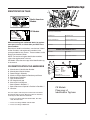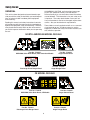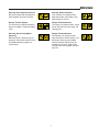
1
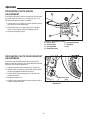
Print Vendor
Instructions
Paper Size:
How to use this file
Operator’s Manuals
• 11x17
• Body - 50 lbs brilliant white offset or equivalent
• Cover - on pre-printed two tone “Swash” stock.
Press:
• Body - 1 color, 2-sided
• Cover - 1 color, 1 sided
Bindery:
• Saddle stitch, face trim
*if too thick for saddle stitch, tape bind
Covers:
• FRONT COVER is present at the beginning of the file.
• BACK COVER is the page immediately after the front cover.
• The part number for this manual (typically a 172_____ number) is
located on the front cover.
• This file may contain several manual which differ only by their covers.
See the part number at the bottom of the cover page. .
Body:
• The body for all manuals is identical regardless of the cover.
• Odd number pages are always right hand pages, even number pages
are always left hand pages.
General:
• This instruction sheet is NOT part of the manual and must not be
printed.
• Pages labeled “THIS PAGE INTENSIONALLY BLANK” are placement
pages and should NOT be printed.
THIS PAGE INTENTIONALLY BLANK
(FOR PLACEMENT ONLY - DO NOT PRINT)
OPERATOR’S
MANUAL
Large Frame
Snowthrower
860 Series Large Frame Snowthrower
Mfg. No.
1693984
1693985
1694242
Description
860M, 8HP Snowthrower
860M, 8HP Snowthrower (Export)
860E, 8HP Snowthrower
960 Series Large Frame Snowthrower
Mfg. No.
1694435
1694439
Description
960M, 9HP Snowthrower (Export)
960E, 9HP Snowthrower
1722659-04
Rev 4/2003
TP 100-2491-04-LW-S
MANUFACTURING, INC.
500 N Spring Street / PO Box 997
Port Washington, WI 53074-0997
www.simplicitymfg.com
© Copyright 2003, Simplicity Manufacturing, Inc.
All Rights Reserved. Printed in USA.
Table of Contents
Safety Rules & Information
General Operation ...........................................2
Slope Operation...............................................2
Children ...........................................................3
Emissions ........................................................3
Service & Maintenance ...................................3
ANSI B71.3-1995 Warnings ............................4
Identification Tags............................................5
Decals..............................................................6
Safety Icons .....................................................7
Features, Controls, & Operation
Control Locations.............................................8
Starting Controls............................................10
Ground Speed Controls.................................11
Auger Control ................................................11
Deflector Controls..........................................11
Scraper Height...............................................11
Traction Lock Control .....................................11
General Operation
Checks Before Each Start-Up .......................12
Starting The Engine.......................................13
Operating The Snowthrower..........................14
Ground Speed Selector .................................14
Engine Speed ................................................14
Deflector ........................................................15
Scraper Bar & Skid Shoes.............................15
Free Wheeling and Traction Drive Lock .........16
After Each Use ..............................................16
Regular Maintenance
Schedule........................................................17
Checking Tire Pressure .................................17
Checking Auger Gear Case Lubrication ........17
Lubrication .....................................................18
Check / Lube Free-Hand Linkage..................19
Storage ..........................................................19
Troubleshooting, Adjustment, & Service
Troubleshooting .............................................20
Speed Selector Pivot Adjustment ..................22
Traction Drive System Adjustment.................22
Auger Drive System Adjustment....................23
Discharge Chute Pinion Adjustment..............24
Discharge Chute Gear Bracket Adj................24
Belt Replacement ..........................................25
Shear Pin Replacement.................................26
Specifications ....................................................27
Replacement Parts & Maintenance Items ...... 28
Technical Manuals.............................................28
WARNING
WARNING
You must read, understand and comply with all safety
and operating instructions in this manual before
attempting to set-up and operate your snowthrower.
Engine exhaust from this product contains
chemicals known, in certain quantities, to cause
cancer, birth defects, or other reproductive harm.
Failure to comply with all safety and operating
instructions can result in loss of machine control,
serious personal injury to you and /or bystanders,
and risk of equipment and property damage. The
triangle in the text signifies important cautions or
warnings which must be followed.
1
Safety Rules & Information
Read these safety rules and follow them closely. Failure to obey these rules could result in loss of control
of unit, severe personal injury or death to you, or bystanders, or damage to property or equipment.
The triangle
in text signifies important cautions or warnings which must be followed.
GENERAL OPERATION
• Read, understand, and follow all instructions in the
manual and on the unit before starting.
• Only allow responsible adults, who are familiar with
the instructions, to operate the unit (local regulations
can restrict operator age).
• Clear the area of objects such as rocks, toys, wire,
etc., which could be picked up and thrown.
• Be sure the area is clear of other people. Stop unit if
anyone enters the area.
• Always look down and behind before and while travelling in reverse.
• Be aware of the discharge direction and do not point
it at anyone. Do not point the discharge at glass
enclosures, automobiles, or windows.
• Disengage all clutches (release drive and auger control levers) before starting the engine.
• Never leave a running unit unattended. Always disengage the auger and traction controls, stop engine,
and remove keys.
• Stop engine before unclogging chute.
• Operate only in daylight or good artificial light.
• Do not operate the unit while under the influence of
alcohol or drugs.
• Watch for traffic when operating near or crossing
roadways.
• Use extra care when loading or unloading the unit
into a trailer or truck.
• Keep in mind the operator is responsible for accidents occurring to other people or property.
• Data indicates that operators, age 60 years and
above, are involved in a large percentage of power
equipment-related injuries. These operators should
evaluate their ability to operate the unit safely enough
to protect themselves and others from injury.
• All operators should seek and obtain professional
and practical instruction.
• Always wear substantial footwear and appropriate
winter clothing. Wear foot-ware that improves traction on slippery slopes. DO NOT wear long scarves
or loose clothing that could become entangled in
moving parts.
• Before using, always visually check that all hardware
is present, in-tact, and secure. Replace worn or
damaged parts.
• Never operate the machine with defective guards, or
without safety protective devises in place.
• Stop engine before: refuelling, removing an attachment, making adjustments (unless the adjustment
can be made from the operator’s position).
• Follow the manufacturer’s recommendation for wheel
weights or counterweights.
• Adjust skid shoe height to clear gravel or crushed
rock surfaces.
• Do not touch snowthrower parts which may be hot
from operation. Allow such parts to cool before
attempting to service the unit.
SLOPE OPERATION
Do
• See your authorized dealer for recommendations
counterweights to improve stability.
• Travel up and down slopes, not across.
• Remove obstacles such as rocks, tree limbs, etc.
• Watch for holes, ruts, or bumps. Uneven terrain could
overturn the unit. Snow can hide obstacles.
• Use slow speed. Tires may lose traction on slopes.
Choose a low gear so that you will not have to stop or
shift while on the slope.
• Keep all movement on the slopes slow and gradual.
Do not make sudden changes in speed or direction.
• Always keep unit in gear especially when traveling
downhill.
Do Not
• Do not start or stop on a slope. If tires lose traction,
disengage the auger and proceed slowly straight
down the slope.
• Do not turn on slopes unless necessary, and then,
turn slowly and gradually downhill, if possible.
• Do not operate near drop-offs, ditches, or embankments. The unit could suddenly turn over if a wheel is
over the edge of a cliff or ditch, or if an edge caves in.
• Do not operate on wet surfaces. Reduced traction
could cause sliding.
• Do not shift to neutral and coast down hills.
WARNING
Never operate on slopes greater than 17.6 percent (10°) which
is a rise of 3-1/2 feet (106 cm) vertically in 20 feet (607 cm)
horizontally.
When operating on slopes use additional wheel weights or
counterweights. See your dealer to determine which weights
are available and appropriate for your unit.
Select slow ground speed before driving onto slope. Travel UP
and DOWN the slope, never across the face, use caution when
changing directions and DO NOT START OR STOP ON
SLOPE.
Slopes are a major factor related to loss-of-control and tipover accidents, which can result in severe injury or death.
All slopes require extra caution. If you cannot back up the
slope or if you feel uneasy on it, do not operate on it.
TP-600-3606-00-LW-UV
2
Safety Rules
EMISSIONS
CHILDREN
• Engine exhaust from this product contains chemicals
known, in certain quantities, to cause cancer, birth
defects, or other reproductive harm.
• Look for the relevant Emissions Durability Period and
Air Index information on the engine emissions label.
Tragic accidents can occur if the operator is not alert to the
presence of children. Children are often attracted to the
unit and the operating activity. Never assume that children
will remain where you last saw them.
• Keep children out of the area and under the watchful
care of another responsible adult.
• Be alert and turn unit off if children enter the area.
• Before and during reverse operation, look behind and
down for small children.
• Never allow children to operate the unit.
• Use extra care when approaching blind corners,
shrubs, trees, or other objects that may obscure
vision.
SERVICE AND MAINTENANCE
• Use extra care in handling gasoline and other fuels.
They are flammable and vapors are explosive.
a) Use only an approved container.
b) Never remove gas cap or add fuel with the
engine running. Allow engine to cool
before refueling. Do not
smoke.
c) Never refuel the unit indoors.
• If fuel is spilled, do not attempt to start the engine but
move the machine away from the area of spillage and
avoid creating any source of ignition until fuel vapors
have dissipated.
• Replace all fuel tank caps and fuel container caps
securely.
• Never fill containers inside a vehicle or on a truck bed
with a plastic bed liner. Always place containers on
the ground away from your vehicle before filling.
• Remove gas-powered equipment from the truck or
trailer and refuel it on the ground. If this is not possible, then refuel such equipment on a trailer with a
portable container, rather than from a gasoline dispenser nozzle.
• Keep nozzle in contact with the rim of the fuel tank or
container opening at all times until fueling is complete. Do not use a nozzle lock-open device.
• If fuel is spilled on clothing, change clothing immediately.
• Maintain or replace safety and instruction labels as
necessary.
• Never run a unit in an enclosed area.
• Keep nuts and bolts tight and keep equipment in
good condition.
• Never tamper with safety devices. Check their proper
operation regularly and make necessary repairs if
they are not functioning properly.
• Keep unit free of debris build-up. Clean up oil or fuel
spillage.
• Stop and inspect the equipment if you strike an
object. Repair, if necessary, before restarting.
• Never make adjustments or repairs with the engine
running unless specified otherwise in the engine
manufacturer’s manual.
• Components are subject to wear, damage, and deterioration. Frequently check components and replace
with manufacturer’s recommended parts, when necessary.
• Check control operation frequently. Adjust and service as required.
• Use only factory authorized replacement parts when
making repairs.
• Always comply with factory specifications on all settings and adjustments.
• Only authorized service locations should be utilized
for major service and repair requirements.
• Never attempt to make major repairs on this unit
unless you have been properly trained. Improper service procedures can result in hazardous operation,
equipment damage and voiding of manufacturer’s
warranty.
• Do not change engine governor settings or overspeed the engine. Operating the engine at excessive
speed can increase the hazard of personal injury.
• Disengage auger and traction, stop the engine,
remove the key, and disconnect the spark plug
wire(s) before: clearing blockages and chutes, performing service work, striking an object, or if the unit
vibrates abnormally. After striking an object, inspect
the machine for damage and make repairs before
restarting and operating the equipment.
3
Safety Rules
ANSI B71.3-1995 WARNINGS
Training
1. Read the operating and service instruction manual
carefully. Be thoroughly familiar with the controls and
the proper use of the equipment. Know how to stop
the unit and disengage the controls quickly.
2. Never allow children to operate the equipment.
Never allow adults to operate the equipment without
proper instruction.
3. Keep the area of operation clear of all persons, particularly small children and pets.
4. Exercise caution to avoid slipping or falling especially
when operating in reverse.
Preparation
1. Thoroughly inspect the area where the equipment is
to be used and remove all doormat, sleds, boards,
wires, and other foreign objects.
2. Disengage all clutches and shift into neutral before
starting engine (motor).
3. Do not operate the equipment without wearing adequate winter outer garments. Wear footwear that will
improve footing on slippery surfaces.
4. Handle fuel with care; it is highly flammable.
(a) Use an approved fuel container.
(b) Never add fuel to a running engine or hot engine.
(c) Fill fuel tank outdoors with extreme care. Never
fill fuel tank indoors.
(d) Replace fuel cap securely and wipe up spilled
fuel.
5. Use extension cords and receptacles as specified by
the manufacturer for all units with electric drive
motors or electric starting motors.
6. Adjust the collector housing height to clear gravel or
crushed rock surfaces.
7. Never attempt to make any adjustments while the
engine (motor) is running (except when specifically
recommended by the manufacturer).
8. Let engine (motor) and machine adjust to outdoor
temperatures before starting to clear snow.
9. Always wear safety glasses or eye shields during
operation or while performing an adjustment or repair
to protect eye from foreign objects that may be
thrown from the machine.
6. When cleaning, repairing, or inspecting make certain
the collector/impeller and all moving parts have
stopped. Disconnect the spark plug wire and keep
the wire away from the plug to prevent accidental
starting.
7. Do not run the engine indoors except for starting the
engine or for transporting the snowthrower in or out
of the building. Open the outside doors; exhaust
fumes are dangerous.
8. Do not clear snow across the face of slopes.
Exercise extreme caution when changing direction on
slopes. Do not attempt to clear steep slopes.
9. Never operate the snowthrower without proper
guards plates, or other safety protective devises in
place.
10. Never operate the snowthrower near glass enclosures, automobiles, window wells, drop-offs, and the
like without proper adjustment of the discharge angle.
Keep children and pets away.
11. Do not overload the machine capacity by attempting
to clear snow at too fast a rate.
12. Never operate the machine at high transport speeds
on slippery surfaces. Look behind and use care
when backing.
13. Never direct discharge at bystanders or allow anyone
in front of the unit.
14. Disengage power to the collector/impeller when
snowthrower is transported or not in use.
15. Use only attachments and accessories approved by
the manufacturer of the snowthrower (such as wheel
weights, counterweights, cabs, and the like).
16. Never operate the snowthrower without good visibility
or light. Always be sure of your footing, and keep a
firm hold on the handles. Walk, never run.
Maintenance and Storage
1. Check shear bolts and other bolts at frequent intervals for proper tightness to be sure the equipment is
in safe working condition.
2. Never store the machine with fuel in the fuel tank
inside a building where ignition sources are present
such as hot water and spacer heaters, clothes dryers,
and the like. Allow the engine to cool before storing
in any enclosure.
3. Always refer to the operator’s guide instructions for
important details if the snowthrower is to be stored for
an extended period.
4. Maintain or replace safety and instruction labels as
necessary.
5. Run the machine a few minutes after throwing snow
to prevent freeze-up of the collector/impeller.
• Always observe safe refueling and fuel handling practices when refueling the unit after transportation or
storage.
• Always follow the engine manual instructions for storage preparations before storing the unit for both short
and long term periods.
• Always follow the engine manual instructions for
proper start-up procedures when returning the unit to
service.
Operation
1. Do not put hands or feet near or under rotating parts.
Keep clear of the discharge opening at all times.
2. Exercise extreme caution when operating on or
crossing gravel drives, walks, or roads. Stay alert for
hidden hazards or traffic.
3. After striking a foreign object, stop the engine
(motor), remove the wire from the spark plug, disconnect the cord on electric motors, thoroughly inspect
the snowthrower for any damage, and repair the
damage before restarting and operating the
snowthrower.
4. If the unit should start to vibrate abnormally, stop the
engine (motor) and check immediately for the cause.
Vibration is generally a warning of trouble.
5. Stop the engine (motor) whenever you leave the
operating position, before unclogging the
collector/impeller housing or discharge guide, and
when making any repairs, adjustments, or inspections.
4
Identification Tags
IDENTIFICATION TAGS
SA
M
North American
Models
PL
E
169XXXX
Serial No.:
kW:
Engine RPM
LpA:
Vibration:
XXXXX
XXX
XXXX
XXX dB(A)
XXX m/s²
PRODUCT
SA
Mfg. No.:
2002
dB(A)
CE Models
REFERENCE
DATA
Model Description Name/Number
M
Unit SERIAL Number
Mower Deck MFG Number
Mower Deck SERIAL Number
When contacting your authorized dealer for replacement parts, service, or information you MUST have
these numbers.
Dealer Name
Date Purchased
Record your model name/number, manufacturer’s identification numbers, and engine serial numbers in the
space provided for easy access. These numbers can be
found in the locations shown.
Engine Make
Engine Model
Engine Type/Spec
Engine Code/Serial Number
PL
Unit MFG Number
Simplicity Mfg. Inc.
Port Washington, WI USA 53074-0997
E
ENGINE REFERENCE DATA
NOTE: For location of engine identification numbers,
refer to the engine owner’s manual.
CE Models: Place the extra copy of the identification tag
in the manual
A
B
F
G
I
C
CE IDENTIFICATION TAG MARKINGS
A.
B.
C.
D.
E.
F.
G.
H.
I.
J.
K.
D
Manufacturer’s Identification Number
Manufacturer’s Serial Number
Power Rating in Kilowatts
Maximum Engine Speed in Rotations per Minute
Manufacturer’s Address
Year of Manufacture
CE Compliance Logo
Mass of Unit in Kilograms
Sound Power in Decibels ***
Sound Pressure at Operator’s Position in Decibels **
Vibration*
J
Mfg. No.:
169XXXX
Serial No.:
kW:
Engine RPM
LpA:
Vibration:
XXXXX
XXX
XXXX
XXX dB(A)
XXX m/s²
2002
dB(A)
K
Simplicity Mfg. Inc.
Port Washington, WI USA 53074-0997
E
CE Models:
Place copy of
Identification Tag here.
This unit complies with European Harmonized Lawn Mower
Standard EN 836, European Machinery Directive 98/37/EC,
and European EMC Directive 89/336/EC
* Tested according to EN 836:1997/A2:2001, EN 1032:
1996, EN 1033:1995
** Tested according to EN836:1997/A2:2001
*** Tested according to 2000/14/EC
5
H
Safety Decals
GENERAL
All WARNING, CAUTION, and instructional messages
on your unit should be carefully read and obeyed.
Personal bodily injury can result when these instructions
are not followed. The information is for your safety and it
is important. The safety decals below are on your unit.
This unit has been designed and manufactured to provide you with the safety and reliability you would expect
from an industry leader in outdoor power equipment
manufacturing.
If any of these decals are lost or damaged, replace them
at once. See your local dealer for replacements.
Reading this manual and safety instructions it contains
will provide you with the necessary basic knowledge to
operate this equipment safely and effectively. We have
also placed several safety labels on the unit to remind
you of this important information while you are operating
the unit.
These labels are easily applied and will act as a constant
visual reminder to you, and others who may use the
equipment, to follow the safety instructions necessary for
safe, effective, operation.
NORTH AMERICAN MODEL DECALS
Part No. 1722643
WARNING / Main Dash Decal, North American Models
Part No. 1722674
Discharge Chute Danger Decal
Part No. 1722640
Auger Control Decal
Part No. 1716532
Auger Danger Decal
CE MODEL DECALS
Part No. 1722639
WARNING / Main Dash Decal, CE Models
Part No. 1722641
Discharge Chute Danger Decal
Part No. 1722640
Auger Control Decal
Part No. 1722642
Auger Danger Decal
6
Safety Icons
Warning: Read Operator’s Manual.
Warning: Dismemberment.
Read and understand the Operator’s
Manual before using this machine.
This machine can amputate limbs.
Keep bystanders and children away
when engine is running.
Danger: Thrown Objects.
Danger: Dismemberment.
This machine is capable of throwing
objects and debris. Keep bystanders
away.
The auger can amputate limbs. Keep
hands and feet away from auger and
rotating parts.
Warning: Remove Key Before
Servicing.
Danger: Dismemberment.
The impeller can amputate limbs.
Stop the engine, remove the key, and
disconnect spark plug wire before
clearing the discharge chute or performing service work. Keep hands
and feet away from impeller and rotating parts.
Remove the key, disconnect spark
plug wire, and consult technical literature before performing repairs or
maintenance.
7
Features, Controls, &
Operation
Please take a moment
and familiarize
yourself with the
name, location, and
function of these
controls so that you will
better understand the
safety and operating
instructions provided in
this manual.
ALL MODELS
1,2..
TECUMSEH MODELS
BRIGGS & STRATTON MODELS
8
Features & Controls
CONTROL LOCATIONS
The information below briefly describes the function of individual controls. Starting, stopping, and driving require the
combined use of several controls applied in specific sequences. To learn what combination and sequence of controls
to use for various tasks see the OPERATION section.
1,2.. Speed Selector
Fuel
Selects forward speeds 1-5 and reverse speeds 1-2.
Fuel tank filler cap (see illustration). The fuel shut off
valve is located under the fuel tank. Close the valve
when the snowthrower is not in use. Open the valve
before stating.
Traction Control / Free Hand™ Lock
Engages traction drive to wheels when depressed. Also
locks auger control when depressed simultaneously.
Releasing the traction control lever releases the Free
Hand™ auger control lock and stops the drive wheels.
Starter Handle
Used to pull-start the engine.
Auger Control
Primer Button
Engages the auger/impeller when depressed. Releasing
the control stops the auger/impeller.
Primes carburetor for faster cold starting.
Throttle Lever
Chute Direction Control
Controls engine speed. Move toward the hare icon for
faster engine speed, move toward the turtle icon for
slower engine speed. Move the throttle all the way to
STOP to stop the engine.
Rotates the discharge chute to desired position.
Chute Deflector Knob
Engine Key
Locks chute deflector in desired position
Traction Lock Pins
Prevents starting of engine without key. Stops engine
when removed.
The traction drive to each wheel can be locked and
unlocked with the Traction Lock Pins (H, Figure 4) to permit the unit to “free-wheel,” allowing easier manual handling and transport of the snowthrower.
Choke Knob
Adjusts air/fuel mix for easier cold weather starting.
Electric Start Button (Optional)
Activates electric starter.
9
Engine Controls
STARTING CONTROLS
Tecumseh Models
See Figure 1 for the following instructions.
Units with Optional Electric Start
A
B
A. Electric Start Button - The Electric Start Button
(A) activates an electric starter mounted to the
engine, eliminating the need to pull the starter handle. The Electric Start Button operates on 120 Volts
AC, which is provided by connection to the extension
cord provided with units equipped with this feature.
Connect this extension cord ONLY to a properly
grounded 3 prong electrical outlet.
C
Manual Start
B. Fuel Valve - The fuel valve (B) is located under the
fuel tank. It is used to turn the fuel supply off when
the unit is not in use.
D
C. Starter Handle - The starter handle (C) connects to a
the starter cord to manually start the engine. Pulling
starter handle rapidly turns the engine over for starting.
G
F
E
Briggs & Stratton Models
D. Primer Button - When pressed, the primer button
(D) provides initial fuel to help start a cold engine.
Normally, pressing the primer button twice will provide enough fuel to start a cold engine. A hot engine
may not require priming
G
F
B
E
A
C
E. Throttle Lever - The throttle lever (E) controls the
engine speed. For best overall performance, the
throttle lever should be set to the FAST position. Use
the SLOW position only for warming the engine, or to
help prevent snow/ice freeze-up when shutting the
unit down for the day.
D
F. Engine Key - The Engine Key (F) prevents the
engine from being started by unauthorized individuals. The key must be fully inserted into the key slot
for the unit to start. The key is also used to stop the
engine by pulling the key out of the key slot.
G. Choke Knob - The Choke Knob (G) adjusts the
air/fuel mixture, and is used to help start a cold
engine by providing a richer mixture. Once the engine
is warm and running smoothly, the Choke Knob
should be set to the off position to provide a normal
air/fuel mix.
Figure 1. Engine Controls
A. Electric Start Button (Optional)
B. Fuel Valve
C. Starter Handle
D. Primer Button
E. Throttle Lever
F. Engine Key
G. Choke Knob
10
Controls
GROUND SPEED CONTROLS
A
C
A. Speed Selector - This lever (A, Figures 2 & 3) is
used to set the ground speed of the snowthrower.
B
D
The snowthrower has five forward speeds, 1–5, and
two reverse speeds, 1–2. No neutral position or gate
is required, since the traction drive design automatically provides "neutral" (no forward or reverse movement), whenever the Drive Control is released.
B. Traction & Free Hand™ Control - This control
engages the traction drive as the lever (B, Figures 2
& 3) is depressed, and disengages the traction drive
when the lever is released. When both levers are
depressed the Free Hand™ control is activated. This
allows the auger control to be released yet the auger
remains engaged until the traction Free Hand™ is
released. NOTE: Changing ground speeds must only
be done while the Drive Control is in the disengaged
(fully released) position.
Figure 2. Operator's Control Position
A. Speed Selector
C. Auger Control
B. Traction Control
D. Chute Direction Control
AUGER CONTROL
C. Auger Control - The Auger Control clutch lever (C
Figures 2 & 3), engages the auger drive when the
lever is depressed and disengages the auger drive
when the lever is released (unless Traction Free
Hand™ control is also depressed-see above).
D
C
B
A
DEFLECTOR CONTROLS
E
F
D. Chute Direction Control - The Chute Direction
Control (D, Figures 2 & 3), allows the discharge chute
to be rotated to throw snow in the desired direction.
Snow may be thrown at any angle from straight left,
to straight forward, to straight right.
E. Chute Deflector - Controls the distance snow is
thrown. Tilting the Chute Deflector (E, Figures 2 & 3)
UP provides a higher stream and greater distance,
while tilting the deflector DOWN provides a lower
stream and less distance.
H
F. Chute Deflector Knob - This knob (F, Figures 2 & 3)
allows the discharge Chute Deflector (E, Figures 2 &
3) to be locked in the desired tilt position.
G
Figure 3. Snowthrower Controls
A. Speed Selector
E. Chute Deflector
B. Traction Drive Control F. Chute Deflector Knob
C. Auger Control
G. Skid Shoes
D. Chute Control
H. Traction Lock Pins
SCRAPER HEIGHT
G. Scraper Bar Height Control - The Skid Shoes (G,
Figure 3) control the height the scraper bar (located
at the bottom of the auger housing). The scraper bar
allows smooth surfaces (such as concrete or asphalt
driveways) to be scraped clean of snow. On surfaces
such as gravel, the scraper bar should be adjusted
higher — so that it will not pick up gravel or debris.
TRACTION LOCK CONTROL
H. Traction Lock Pins - The traction drive to each
wheel can be locked and unlocked with the Traction
Lock Pins (H, Figure 3) to permit the unit to “freewheel,” allowing easier manual handling and transport
of the snowthrower.
11
Operation
GENERAL OPERATION
WARNING
CHECKS BEFORE EACH START-UP
This unit is a “two-stage” snowthrower.
1. Make sure all safety guards are in place and all nuts,
bolts and clips are secure.
The first stage is the auger, which feeds the snow
back into the impeller housing. The second stage
is the impeller, which throws the snow out the
discharge chute. If bodily contact is made with
the auger or impeller when they are rotating,
severe personal injury will occur.
2. Check the engine oil level. See your engine Owner’s
Manual for procedure and specifications.
3. Check to make sure spark plug wire is attached and
spark plug is tightened securely. If necessary, torque
spark plug to 15 ft. lbs.
To avoid injury, keep others and yourself away
from the auger and the discharge chute whenever
the engine is running. Read and follow all of the
safety rules and warnings in this manual.
4. Check the fuel level. Add fuel until the fuel level is no
closer than 1/2 from the top of the tank to provide
space for expansion. See your engine owner’s manual for fuel recommendations.
WARNING
5. Check the scraper bar to make sure it is set at the
desired height. Adjust the skid shoes if necessary.
To avoid serious injury, do not put your hands
into the auger housing or discharge chute. If
auger stalls or chute becomes plugged, use the
following procedure to remove objects or clear
the chute:
1. Release both the Drive and Auger Control levers.
2. Shut off the engine.
3. Remove the Engine Key.
4. Wait for moving parts to stop.
5. Disconnect spark plug wire.
6. Use a narrow board to remove foreign objects
and clear the chute or auger. Never put your
hands into the auger or discharge chute.
6. Check the drive control (B, Figure 2), and auger control (C, Figure 6) for proper operation. If adjustment is
required, see the Adjustments Section for procedures.
7. Check the chute direction control (D, Figure 2) for
proper operation. The discharge chute should rotate
freely in both directions. See the Adjustments Section
for adjustment procedures and troubleshooting.
8. Check the chute deflector (E, Figure 3) for proper
operation. The deflector should pivot freely up and
down when the chute deflector knob is loosened. If
adjustment is required, see the Adjustments Section
for procedures.
9. Position the chute at the desired starting direction
and set the deflector at the desired angle.
WARNING
10. Check the speed selector (A, Figure 2) for smooth
operation. The control must move freely into each
speed position gate and remain in position when
released. If the speed selector does not move freely
into all forward and reverse speed positions, contact
your local authorized dealer for assistance.
For your safety, operation on slopes should be in
an up and down direction only. If it becomes
necessary to move across the face of a slope, use
caution and do not blow snow. Be very careful
when changing direction on a slope.
Proper winter footwear is recommended for the
operator to help prevent slipping. Never attempt
to clean snow from excessively steep slopes. The
maximum slope for any operation is 17.7% (10º).
WARNING
Gasoline is highly flammable and must be
handled with care. Never fill the tank when the
engine is hot or running. Always move outdoors
to fill the tank. Keep snowthrower and gasoline
away from open flame or spark.
12
Operation
STARTING THE ENGINE
Tecumseh Models
Refer to Figure 4.
1. Turn the fuel valve (B) to the ON position.
A
B
2. Insert the engine key (F) into the engine key slot.
3. Move the throttle lever (E) to the FAST position.
C
4. Fully close the choke (G) if engine is cold (a warm
engine may not require choking).
5. Push the primer button (D) two times if engine is cold
(a warm engine may not require priming).
6. Pull starter handle (C) rapidly, or push starter button
if equipped with the electric start. Do not allow the
starter handle to snap back—let the starter rope
rewind slowly—while keeping a firm grip on the
starter handle.
D
7. As the engine starts and begins to operate evenly,
open the choke (G) slowly and set the throttle lever to
SLOW. If the engine falters, turn the choke knob
clockwise until the engine runs smoothly, and let it
run briefly before returning the choke to the OPEN
position.
G
F
E
Briggs & Stratton Models
G
F
NOTE: Allow the engine to warm up at SLOW throttle for
a few minutes before operating the snowthrower at full
speed. The engine will not develop full power until it
reaches operating temperature.
B
E
A
C
D
Figure 4. Engine Controls
A. Electric Start Button (Optional)
B. Fuel Valve (Under Tank)
C. Starter Handle
D. Primer Button
E. Throttle Lever
F. Engine Key
G. Choke Knob
13
Operation
OPERATING THE SNOWTHROWER
C
1. Rotate the discharge chute to the desired direction.
A
D
B
2. Set the speed selector to the desired forward speed.
3. Fully press and hold the auger control (C, Figure 5)
on the right-hand grip to begin auger rotation. To disengage the auger, completely release the lever.
4. Fully press and hold the traction drive control lever
(B, Figure 5) on the left-hand grip to engage the traction drive and begin moving the snowthrower. To disengage the traction drive, completely release the
lever.
If the auger control (C) and traction control (B) are
depressed simultaneously, the Free-Hand mechanism will be activated. When activated, the auger
control (C) will remain engaged when its control lever
is released so long as the traction drive control (B) is
engaged. This allows the operator to rotate the discharge chute (D) without stopping.
Figure 5. Operator's Control Position
A. Speed Selector
C. Auger Control
B. Traction Drive Control D. Chute Direction Control
Releasing the traction control (B) will disengage both
the auger and traction drive.
5. Select forward or reverse speeds as needed using
the speed selector (A, Figure 5). Release the drive
control lever whenever changing drive speeds.
NOTE: After 5 - 10 hours of use, it may be necessary
to adjust the tension on the traction drive rod. See
"Traction Drive Clutch Rod Adjustment" in the
Adjustments Section for the adjustment procedure.
GROUND SPEED SELECTOR
Use the speed selector (A, Figure 5) to control the drive
speed of the snowthrower. There are five forward speeds
and two reverse speeds.
Throttle
Lever
Use the lower speeds to blow deep or wet snow. Use the
higher speeds to blow light snow or to drive the snowthrower without blowing snow.
To change speeds, first release the traction drive control
lever (B, Figure 5), then move the speed selector to the
desired speed setting. Fully press the traction drive control lever to resume operation.
Throttle
Lever
ENGINE SPEED
Run the engine at full throttle when operating. Use the
engine throttle lever (See Figure 6) to set the engine
speed. Slide the throttle lever UP to increase engine
speed, and DOWN to reduce speed.
Figure 6. Engine Speed Selection
14
Operation
DEFLECTOR
Chute
Deflector Knob
The distance of the discharged snow is mainly controlled
by the position of the deflector (Figure 7). (Engine speed
also affects distance of discharge.)
The more the deflector is tilted UP, the farther snow will
be thrown. Loosen the deflector knob, tilt the deflector
UP or DOWN, and then retighten the knob when the
desired angle has been chosen.
Chute
Deflector
Figure 7. Chute Deflector Adjustment
SCRAPER BAR & SKID SHOES
On smooth surfaces such as concrete or asphalt, the
scraper bar should scrape the surface. On surfaces such
as gravel, the scraper bar should be high enough so that
it will not pick up gravel or debris.
The height of the scraper bar is controlled by raising or
lowering the Skid Shoes (See Figure 8).
1. To raise the scraper bar height, rest the scraper bar
on a strip of wood equal in thickness to the desired
height.
Scraper
Bar
Skid Shoe
Nuts
2. Make sure the scraper bar is parallel to the ground
surface.
3. Loosen the skid shoe nuts and let the skid shoes
drop to the surface.
Skid Shoe
4. Tighten the nuts, making sure the Skid Shoes are
adjusted equally and are parallel to the surface.
Figure 8. Skid Shoe Adjustment
5. To lower the height of the scraper bar, raise the Skid
Shoes.
6. If the scraper bar becomes worn, it can be replaced
by removing the hardware attaching it to the
snowthrower.
15
Operation
FREE-WHEELING AND
TRACTION DRIVE LOCK
For easy turning when pushing the snowthrower, you
can disengage the traction drive at one or both wheels
by using the Traction Lock Pins (See Figures 9 & 10).
Klik-Pin In
OUTER Hole
1. Turn the unit off, remove the Engine Key, and disconnect the spark plug wire.
2. To DISENGAGE the traction drive lock, insert the
Traction Lock Pin through the outer hole in the axle.
(See Figure 9).
3. To ENGAGE the traction drive lock, insert the pin
through the hub and axle (See Figure 10). If the hole
in the hub is not aligned with the inner hole in the
axle, push the snowthrower until the holes align and
install the Traction Lock Pin.
NOTE: For best drive performance engage both wheels.
For easier turning disengage one wheel.
Figure 9. Traction Drive Lock - Disengaged
AFTER EACH USE
Klik-Pin In
INNER Hole
Normal use of the snowthrower may result in a build-up
of packed snow in and around the starter cord housing
and around engine controls. Heat from the engine will
usually prevent the snow from freezing solid while the
unit is running, but after the engine is shut down, some
snow may continue melting from engine heat, and later
freeze around some moving parts as the unit cools.
After each period of use, follow these steps to prevent
freeze-up caused by ice formation in and around the
engine controls and external parts.
1. Before shutting off the engine, pull the starter rope
out 2 - 3 times, and allow it to rewind slowly. This will
help clear packed snow from the starter cord area.
Run engine a few minutes before shutting off.
Figure 10. Traction Drive Lock - Engaged
2. Stop the engine by moving the throttle lever (See
Figure 6) down, or by pulling out the engine key.
WARNING
3. Disconnect the spark plug wire, and position it away
from the spark plug.
Never store snowthrower, with gasoline in the
engine or fuel tank, in a heated shelter or in an
enclosed, poorly ventilated enclosure. Gasoline
fumes may reach an open flame, spark or pilot
light (such as a furnace, water heater, clothes
dryer, etc.) and cause an explosion.
4. Brush snow and ice from the snowthrower. Be sure to
clear engine and snowthrower controls, discharge
chute, worm and chute rod gears, clutch rod areas,
and anywhere else snow has accumulated.
5. Always remove the engine key and store in a safe
place to prevent unauthorized use.
Handle gasoline carefully. It is highly flammable
and careless use can result in serious fire
damage to people and property.
6. If the snowthrower is kept in a cold shelter, fill the fuel
tank to prevent condensation. Do not store near
sparks or flame.
Drain fuel into an approved container outdoors
away from open flame or sparks.
NOTE: The Engine Owner’s Manual contains further
information on preventing ice formation and freeze-up.
16
Maintenance
SCHEDULE
CARE REQUIRED
FREQUENCY
LUBRICATION
Check auger gear case lubrication.**
25 Hours
Simplicity Winter Weight
Worm Gear Oil
Lubricate snowthrower.
10 Hours
10W Oil and Grease
Check tire pressure.
Monthly
N/A
Change engine oil.*✛
50 Hours✛
See Engine Manual
Yearly
See Engine Manual
4-6 Hours
N/A
Yearly
Lithium Grease
Clean or replace spark plug.✛
Check drive linkage/belt tension
Lubricate Axle Shafts
* Change original oil after two hours of operation.
** Check oil level each fall and spring.
✛ See your engine Owner’s Manual.
CHECKING TIRE PRESSURE
The air pressure in each tire should be 20 psi (136 kPa)
and should be equal for both tires for best performance.
Be sure to keep caps on valves to prevent entry of debris
into the valve stem when tires are filled.
Figure 11. Checking Tire Pressure
CHECK AUGER
GEAR CASE LUBRICATION
1. Place the snowthrower on a level surface.
2. Remove the fill plug (Figure 12).
3. Check the lubricant level. It should be level with the
lower edge of the plug opening. If not, add Simplicity
Winter Weight Worm Gear Oil (available from your
dealer).
4. Re-install fill plug, and tighten securely.
Fill Plug
Figure 12. Checking Auger Gear Case Lubrication
17
Maintenance
LUBRICATION
IMPORTANT NOTE
It is very important that grease fittings on the auger shaft
are lubricated regularly. If auger rusts to shaft, damage to
worm gear may occur if shear pins do not break.
To prevent wheels rusting to axles, it is also necessary
to remove the wheels and grease the axles regularly.
Remove wheels and grease axles once each year.
There are two grease fittings on the auger shaft. Wipe
the fittings clean and apply grease, using a grease gun.
Also apply grease on other points indicated.
Figure 14. Lubricate Points Where Chute Contacts
Flange (oil); Lubricate Ring Gear and Pinion Gear
While Rotating Spout (grease)
Apply medium weight (10W) oil to points shown(See
Figures 13 - 17).
Apply 5W-50 synthetic motor oil to the friction disk hex
shaft (see Figure 13).
Generally, all moving metal parts should be oiled where
contact is made with other parts. Keep oil and grease off
belts, pulley grooves, drive disc, and friction disc.
LUBRICATION NOTES:
Grease locations indicated by grease gun symbol.
Use grease fittings when present. Disassemble
parts to apply grease to moving parts when grease
fittings are not installed.
Figure 15. Lubricate Free Hand Control
Oil locations indicated by oil can symbol. Do not
allow oil to drip onto traction drive or friction disc.
Hex Shaft
Figure 16. Grease Axles & Lube Control Levers
Figure 17. Lubricate Deflector Hinges
Figure 13. Auger Pulley Belt Stops
(shown with bottom cover removed)
A. Nuts
C. Auger Pulley
B. Belt Stops
18
Storage
CHECK / LUBRICATE FREE-HAND
LINKAGE
WARNING
Never store the unit, with gasoline in engine or
fuel tank, in a heated shelter or in enclosed,
poorly ventilated enclosures. Gasoline fumes may
reach an open flame, spark or pilot light (such as
a furnace, water heater, clothes dryer, etc.) and
cause an explosion.
Check the function of the Free-Hand controls: the controls should function as described in the CONTROLS
section. It is critical for the safe operation of the unit
that the controls disengage when released.
If the controls do not function properly, lubricate them
(Figure 15). If lubrication does not rectify the problem,
see your dealer. Under no circumstances should the unit
be used if the controls are not functioning properly.
Handle gasoline carefully. It is highly flammable
and careless use could result in serious fire
damage to your person or property.
Drain fuel into an approved container outdoors
away from open flame or sparks.
TEMPORARY STORAGE
(30 DAYS OR LESS)
7. Completely grease and oil as outlined in the Normal
Care section.
8. Drain fuel system completely or add a gasoline stabilizer
to the fuel system. If you have chosen to use a fuel stabilizer and have not drained the fuel system, follow all
safety instructions and storage precautions in this manual to prevent the possibility of fire from the ignition of
gasoline fumes. Remember, gasoline fumes can travel
to distant sources of ignition and ignite, causing risk of
explosion and fire.
Remember, the fuel tank will still contain some gasoline, so
never store the unit indoors or in any other area where fuel
vapor could travel to any ignition source. Fuel vapor is also
toxic if inhaled, so never store the unit in any structure used
for human or animal habitation.
Here is a checklist of things to do when storing your unit
temporarily or in between uses:
NOTE: Gasoline, if permitted to stand unused for extended
periods (30 days or more), may develop gummy deposits
which can adversely affect the engine carburetor and cause
engine malfunction. To avoid this condition, add a gasoline
stabilizer to the fuel tank or drain all fuel from the system
before placing unit in storage.
• Keep in an area away from where children may come
into contact with it. If there’s any chance of unauthorized
use, remove the key.
• Clean all debris from the unit.
LONG TERM STORAGE
(LONGER THAN 30 DAYS)
STARTING AFTER
LONG TERM STORAGE
Before you store your unit for the off-season, read the
Maintenance and Storage instructions in the Safety Rules
section, then perform the following steps:
Before starting the unit after it has been stored for a long
period of time, perform the following steps.
1. Drain crankcase oil and refill with a grade of oil that will
be required when unit is used again.
1. Remove any blocks from under the unit.
2. Coat all bare metal surfaces with paint or light coat of oil
to prevent rusting.
3. Unplug the exhaust outlet and air cleaner.
2. Install the battery if it was removed.
3. Clean external surfaces and engine.
4. Fill the fuel tank with fresh gasoline. See engine
manual for recommendations.
4. Prepare engine for storage. See engine owner’s
manual.
5. See engine owner’s manual and follow all instructions
for preparing engine after storage.
5. Clean any dirt from the engine housing.
6. Check crankcase oil level and add proper oil if
necessary.
6. Cover air intake and exhaust outlet tightly with plastic or
other waterproof material to keep out moisture, dirt and
insects.
7. Inflate tires to proper pressure.
8. Start the engine and let it run slowly. DO NOT run at
high speed immediately after starting. Be sure to run
engine only outdoors or in well ventilated area.
19
Troubleshooting,
Adjustments, & Service
TROUBLESHOOTING
This section provides troubleshooting and service
instructions. Locate the problem and check the possible
cause/remedy in the order listed.
WARNING
Before performing any adjustment or service to
snowthrower, stop the engine and wait for moving
parts to stop. Remove the key. To prevent accidental
starting, disconnect the spark plug wire and fasten
away from the plug.
Also, refer to the engine manufacturer’s Owner’s Manual
for additional information.
For problems not covered here, contact your local dealer.
PROBLEM
Engine fails to start.
POSSIBLE CAUSE
1.
2.
3.
4.
5.
Key is OFF.
Failure to Prime cold Engine
Fuel valve is in CLOSED position.
Out of fuel.
Choke OFF - cold engine.
6. Engine flooded.
7. Spark plug not sparking.
8. Water in fuel, or old fuel.
Engine starts hard or runs poorly.
Auger does not rotate.
REMEDY
1.
2.
3.
4.
5.
Push key in to the ON position.
Press Primer Button twice and restart.
Turn valve to OPEN position.
Fill fuel tank.
Turn choke to ON, set throttle to
FAST.
6. Turn choke to OFF; try starting.
7. Check gap. Gap plug, clean electrode, or replace plug as necessary.
8. Drain tank (Dispose of fuel at an
authorized hazardous waste facility).
Fill with fresh fuel.
1. Fuel mixture too rich.
1. Move choke to OFF position.
2. Carburetor adjusted incorrectly.
2. See your dealer for adjustments.
3. Spark plug faulty, fouled, or gapped
improperly.
3. Clean and gap, or replace.
4. Fuel Cap Vent is blocked.
4. Clear vent.
1. Auger Control not engaged.
2. Foreign matter blocking auger.
1. Engage Auger Control.
2. STOP engine and REMOVE the key.
DISCONNECT the spark plug wire.
Clear auger using a narrow board.
See warning in SAFETY RULES.
3. Tighten to remove slack. See auger
clutch rod adjustment.
4. Check auger drive belt adjustment.
5. Replace belt.
6. Replace shear pin.
3. Auger drive clutch rod slack.
4. Auger drive belt slipping.
5. Broken belt.
6. Shear pin broken.
20
Troubleshooting
PROBLEM
Auger rotates, but snow is not
thrown far enough
POSSIBLE CAUSE
REMEDY
1. Chute Deflector too low.
1. Adjust deflector as necessary.
2. Engine speed too slow.
2. Set speed to full throttle.
3. Ground speed too fast.
3. Use slower Speed Selector setting.
4. Snowthrower discharge chute clogged.
4. STOP engine and REMOVE the key.
DISCONNECT the spark plug wire.
Clear auger using a narrow board.
See warning in SAFETY RULES.
5. Auger belt loose or worn.
5. Check Auger Drive Belt Adjustment
Scraper bar does not clean hard
surface.
1. Skid Shoes improperly adjusted.
1. RAISE Skid Shoes (this lowers the
Scraper Bar).
Scraper bar picks up and throws
stones on gravel drive.
1. Skid shoes improperly adjusted.
1. LOWER Skid Shoes (this raises the
scraper bar.)
Poor traction
1. Tires slipping.
1. Check tire pressure and tread.
Auger does not stop when auger
lever is released
1.
2.
3.
4.
1.
2.
3.
4.
Snowthrower does not stop when
drive lever is released
1. Traction drive clutch rod bent or too
tight.
1. Loosen rod to remove slack or
replace. See adjustment procedure.
Snowthrower does not drive when
drive lever is engaged.
1. Traction drive clutch rod loose.
1. Tighten to remove slack. See adjustment procedure.
2. Replace drive belt.
3. Replace chain.
4. Change Traction Lock Pins to INNER
hole to engage traction drive.
5. Replace Disc (see your dealer).
Auger clutch rod too tight or bent.
Auger drive belt out of adjustment.
Auger belt guide out of adjustment.
Free hand control not releasing.
2. Drive belt loose, broken, or stretched.
3. Drive roller chain damaged.
4. Traction Lock Pins in Free-Wheeling
position (OUTER hole).
5. Friction Disc worn.
Discharge control is difficult to
operate.
1. Gearing needs lubrication
2. Worm gear not adjusted properly.
3. Control rod gears misaligned.
Loosen or straighten clutch rod.
Adjust auger belt.
Adjust auger belt guide.
Lubricate free hand linkage.
1. Oil or grease as required.
2. Adjust worm gear. See adjustment
procedure.
3. Adjust gear bracket. See adjustment
procedure.
Snowthrower veers to one side.
1. Tires pressure not equal.
2. One wheel is set in Free-Wheeling
mode. (Traction Lock Pin is in the
OUTER hole).
1. Check tire pressure.
2. Make certain BOTH Traction Lock
Pins are in the INNER holes (to
engage traction drive).
Excessive vibration.
1. Loose parts or damaged auger.
1. STOP engine and REMOVE the key.
DISCONNECT the spark plug wire.
Tighten all hardware. Replace auger
if necessary. If vibration continues,
see your dealer.
Drive fails to move snowthrower
at slow speeds.
1. Traction Drive out of adjustment.
1. Readjust drive, or shift Speed
Selector setting up one speed faster.
21
Adjustments
TRACTION DRIVE SYSTEM
ADJUSTMENT
A
Speed Selector Pivot Adjustment
The Speed Selector is factory set for optimal performance at each forward and reverse speed setting.
However, if drive system components have been
replaced, adjustment may be necessary.
Adjust as follows:
1. Move the ground speed control (A, Figure 18) fully
forward.
2. Loosen the hardware (B) securing the upper and
lower shift rods.
3. Push the lower rod (C) down fully (into the housing).
4. Make sure the ground speed control (A) is in the full
forward (5th gear) position. Tighten the shift rod
hardware (B).
B
C
Traction Drive Clutch Rod & Spring
Adjustment
INITIAL ADJUSTMENT
Figure 18. Speed Selector Linkage Adjustment
A. Ground Speed Lever
B. Shift Rod Hardware
C. Lower Shift Rod
The traction drive clutch rod should initially be adjusted
so that there is no slack in the rod when moved slightly
from side to side, but bellcrank arm remains in fully down
position. To adjust tension on the rod:
1. Loosen adjustment hex nuts (Figure 19).
2. Tighten bottom hex nut while holding rod. Tighten
just until slack in rod is removed.
3. Tighten upper hex nut securely.
Adjustment
Hex Nuts
WARNING
Traction
Drive
Clutch
Rod
Do not over-tighten, as this may cause traction
drive to engage without depressing the traction
Drive Control (bellcrank arm must remain in down
position).
Verify that the rods are not over-tightened: With
Speed Selector in position 1 and traction Drive
Control fully released, push snowthrower
forward. The unit should move forward freely.
Traction Drive
Bellcrank Arm
If unit does not move forward freely, the rod has
been over-tightened. To remedy, loosen tension
on clutch rod slightly, and recheck.
Traction Drive
Clutch Rod
Spring
Figure 19. Traction Drive Clutch Rod Adjustment
22
Adjustments
AUGER DRIVE SYSTEM
ADJUSTMENTS
Auger Drive
Clutch Rod
Auger Drive Clutch Rod Adjustment
WARNING
Auger Lever
Do not over-tighten, as this may lift the idler rod
lever and cause auger drive to be engaged
without depressing the Auger Control.
Adjustment
Hex Nuts
Auger Drive
Clutch Rod Spring
All auger drive adjustment is accomplished through the
auger drive clutch rod. The rod must be adjusted so that
there is 1/32” clearance between the spring hook and the
auger lever (see Figure 20). Proper adjustment allows
the auger brake to engages when the control is released.
To adjust the rod:
Must have 1/32”
gap between
spring hook and
lever.
1. See Figure 20. Loosen adjustment hex nuts.
Figure 20. Auger Drive Clutch Rod adjustment
2. Tighten the upper adjustment nut until there is a 1/32”
gap between the spring hook and the auger lever.
3. Tighten the lower adjustment nut.
4. Recheck that there is a 1/32” gap between the spring
hook and the auger lever.
5. With engine running, fully depress Auger Control, the
auger should engage and run normally.
6. Release Auger Control. The auger must stop within 5 seconds.
7. If auger does not operate properly, stop engine and
recheck clutch rod adjustments.
23
Adjustment
DISCHARGE CHUTE PINION
ADJUSTMENT
F
A
If the discharge chute is difficult to operate, first lubricate
the pinion gear (A, Figure 21) and ring gear (F). If it is
still difficult to operate, adjust as follows:
E
1. Loosen the nut (G, Figure 21) which holds the pinion
gear bracket in the slotted hole.
2. If the pinion gear is too tight against the ring gear,
move it away slightly and then retighten the nut.
B
3. Check the operation again.
D
C
G
Figure 21. Discharge Control
A. Pinion Gear
E. U-shaped Bracket
B. Control Rod
F. Ring Gear
C. Carriage Bolt
G. Nut
D. Slotted Bracket
DISCHARGE CHUTE GEAR BRACKET
ADJUSTMENT
If the Discharge Chute becomes difficult to rotate or
begins to operate erratically, the Chute Direction Control
rod gears may require adjustment:
1. Loosen the gear bracket mounting nuts (Figure 22).
2. Slide the gear bracket into the position that provides
the best engagement between the gears.
3. Tighten the bracket mounting nuts, and check for
smooth operation.
Mounting Nuts
4. Readjust if necessary.
5. Lubricate the chute direction control rod gears with a
medium weight (10W) oil.
Figure 22. Chute Direction Control Gear Bracket
Adjustment
24
Service
Belt Cover
Screws
Figure 23. Belt Cover
Figure 24. Auger Pulley Belt Stops
(shown with bottom cover removed)
A. Nuts
C. Auger Pulley
B. Belt Stops
BELT REPLACEMENT
1. Rotate the spout full right. Loosen the two screws
(Figure 23) securing the belt cover.
2. Tilt the cover forward and work it off the snowthrower.
3. Remove the belt guide (B, Figure 25) by removing
the two capscrews (A), lockwashers and washers.
4. Remove the auger drive belt as follows:
a. Slip the auger drive belt (D, Figure 25) from the
idler pulley by pushing it away from the pulley and
then toward the rear.
b. Remove the belt from the engine pulley. Slip the
belt from under the brake pad.
c. Remove six capscrews from bottom cover to
snowthrower frame. Loosen nuts (A, Figure 24) on
each side to release auger pulley belt stops (B).
Move belt stops and remove belt from pulley (C).
d. Belt can be removed from top or bottom. For more
clearance to remove the belt, engage the traction
drive lever.
5. Remove the traction drive belt as follows:
a. Pull the idler pulley (I, Figure 25) away from the
belt and slip the belt from the pulley.
b. Slip the belt off the traction pulley and then the
engine pulley. The arm for the front idler pulley (G,
Figure 25) may have to be pivoted to provide clearance for removing the belt from the traction pulley.
c. Pull the belt out between the auger pulley (F,
Figure 25) and traction pulley.
A
C
B
D
E
A
F
I
H
G
Figure 25. Belts and Pulleys
A. Capscrews
F. Auger Pulley
B. Belt Guides
G. Idler Pulley, Auger
C. Traction Drive Belt
H. Traction Pulley
D. Auger Drive Belt
I. Idler Pulley, Traction
E. Engine Pulley
25
Service
6. Reverse the procedure to install the belts. Be sure
there are no twists and the belts are properly seated
in the grooves. Adjust the belt stops so there is 1/8”
(3mm) clearance between belt and stop. The pattern
for both belts is shown in Figure 26.
7. Check the traction drive tension and auger drive tension. Follow the procedures under AUGER DRIVE
BELT ADJUSTMENT.
8. Make sure the auger stops when the auger drive
lever is released. Make sure traction drive stops
when the traction drive lever is released. If not, check
the drive tension. If a problem exists, see your dealer.
Belt Stops
A
C
B
D
Belt Stops (Auger Pulley Only)
Figure 26. Belt Pattern (as viewed from front of
snowthrower)
A. Engine Pulley
C. Idler Pulley
B. Drive Belt
D. Driven Pulley
SHEAR PIN REPLACEMENT
WARNING
Do not go near the discharge chute or auger when the
engine is running. Do not run the engine with any
cover or guard removed.
Under most circumstances, if the auger strikes an object
which could cause damage to the unit, the shear pin will
break. This protects the gear box and other parts from
damage.
The shear pins are located on the auger shaft as shown
in Figure 27. To replace the shear pins, tap out broken
pin with a pin punch, and install a new shear pin and cotter pin. Spread the legs of the new cotter pin fully. Do
NOT replace shear pins with anything other than the
correct grade replacement shear pin. See the
REPLACEMENT PARTS section at the back of this manual for the correct part numbers. (Use of bolts, screws or
a harder shear pin will lead to damaged equipment.)
Shear Pins
Figure 27. Shear Pins
26
Specifications
Specifications are correct at the time of printing and are subject to change without notice.
ENGINE:
CHASSIS:
Wheels
- 860, 960
Tire Size: 16 x 4.8
Inflation Pressure: 20 psi (1,37 bar)
Spout Rotation
210 Depress
Impeller
12” (30cm) 4 Blade Ribbon Flighted Steel
Auger Opening Height 19” (47.5 cm)
Drive System
Friction Disc, 5 Forward Speeds, 2 Reverse
8 HP* Tecumseh
Make
Model
Horsepower
Displacement
Oil Capacity
Tecumseh
Snow King
8 @ 3600 rpm
19.43 Cu. in (318.3 cc)
See Engine Owner’s Manual
9 HP* Briggs & Stratton
DIMENSIONS
Make
Model
Horsepower
Displacement
Oil Capacity
Effective Clearing Width
-860
26” (65cm)
-960
26” (65cm)
Briggs & Stratton
Intek Snow
9 @ 3600 rpm
18.6 Cu. in (305 cc)
28 oz. (,84 L)
27
Length
-860
-960
54” (137cm)
54” (137cm)
Height
-860
-960
43” (109cm)
43” (109cm)
Weight
-860
-960
236 lbs (107kg)
235 lbs (106kg)
Replacement Parts & Accessories
REPLACEMENT PARTS
TECHNICAL MANUALS
Replacement parts are available from your authorized
dealer. Always use genuine Simplicity Service Parts.
Additional copies of this manual are available, as well as
fully illustrated parts lists. These manuals show all of the
product’s components in exploded views (3D illustrations
which show the relationship of parts and how they go
together) as well as part numbers and quantities used.
Important assembly notes and and torque values are
also included.
MAINTENANCE ITEMS
Many convenient and helpful service and maintenance
items are available from you authorized dealer. Some of
these items include:
Engine Oil
Touch-Up Paint
Grease Gun Kit
8 oz. Grease Tube
For applicable manuals currently available for your
model, contact our Customer Publications Department at
262-284-8519. Have the information listed in the box
below available when phoning in your request.
Technical manuals can be downloaded from
www.simplicitymfg.com
Tire Sealant
Degrimer/Degreaser
Gas Stabilizer
Model:
Mfg. No.:
Your Name:
Address:
City, State, Zip:
Visa/Mastercard No.:
Card Expiration Date:
28