1
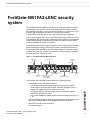
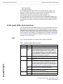
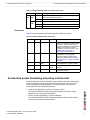
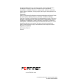
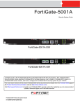
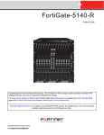
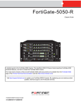
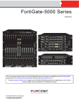
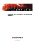
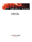
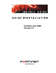
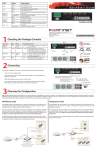
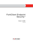
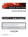
Security System Guide
FortiGate-5001FA2-LENC
A detailed guide to the FortiGate-5001FA2-LENC Security System. This FortiGate-5001FA2-LENC Security System
Guide describes FortiGate-5001FA2-LENC hardware features, how to install the FortiGate-5001FA2-LENC board in
a FortiGate-5000 series chassis, how to configure the FortiGate-5001FA2-LENC security system for your network,
and contains troubleshooting information to help you diagnose and fix problems.
The most recent versions of this and all FortiGate-5000 series documents are available from the FortiGate-5000
page of the Fortinet Technical Documentation web site (http://docs.forticare.com).
Visit http://support.fortinet.com to register your FortiGate-5001FA2-LENC system. By registering you can receive
product updates, technical support, and FortiGuard services.
www.fortinet.com
FortiGate-5001FA2-LENC Security System Guide
01-30000-76602-20080606
Warnings and cautions
Only trained and qualified personnel should be allowed to install or maintain FortiGate-5000 series
equipment. Read and comply with all warnings, cautions and notices in this document.
•
•
•
•
•
•
•
•
•
•
•
•
!
CAUTION: Risk of Explosion if Battery is replaced by an Incorrect Type. Dispose of Used Batteries According
to the Instructions.
!
Caution: You should be aware of the following cautions and warnings before installing FortiGate-5000 series
hardware
Turning off all power switches may not turn off all power to the FortiGate-5000 series equipment.
Except where noted, disconnect the FortiGate-5000 series equipment from all power sources,
telecommunications links and networks before installing, or removing FortiGate-5000 series
components, or performing other maintenance tasks. Failure to do this can result in personal injury or
equipment damage. Some circuitry in the FortiGate-5000 series equipment may continue to operate
even though all power switches are off.
An easily accessible disconnect device, such as a circuit breaker, should be incorporated into the data
center wiring that connects power to the FortiGate-5000 series equipment.
Install FortiGate-5000 series chassis at the lower positions of a rack to avoid making the rack top-heavy
and unstable.
Do not insert metal objects or tools into open chassis slots.
Electrostatic discharge (ESD) can damage FortiGate-5000 series equipment. Only perform the
procedures described in this document from an ESD workstation. If no such station is available, you
can provide some ESD protection by wearing an anti-static wrist strap and attaching it to an ESD
connector or to a metal part of a FortiGate chassis.
Some FortiGate-5000 series components may overload your supply circuit and impact your overcurrent
protection and supply wiring. Refer to nameplate ratings to address this concern.
Make sure all FortiGate-5000 series components have reliable grounding. Fortinet recommends direct
connections to the branch circuit.
If you install a FortiGate-5000 series component in a closed or multi-unit rack assembly, the operating
ambient temperature of the rack environment may be greater than room ambient. Make sure the
operating ambient temperature does not exceed the manufacturer's maximum rated ambient
temperature.
Installing FortiGate-5000 series equipment in a rack should be such that the amount of airflow required
for safe operation of the equipment is not compromised. Refer to the ATCA specification for more
information about cooling and airflow requirements.
This equipment is for installation only in a Restricted Access Location (dedicated equipment room,
service closet or the like), in accordance with the National Electrical Code.
Per the National Electrical Code, sizing of a Listed circuit breaker or branch circuit fuse and the supply
conductors to the equipment is based on the marked input current rating. A product with a marked input
current rating of 25 A is required to be placed on a 40 A branch circuit. The supply conductors will also
be sized according to the input current rating and also derated for the maximum rated operating
ambient temperature, Tma, of the equipment.
FortiGate-5000 series equipment shall be installed and connected to an electrical supply source in
accordance with the applicable codes and regulations for the location in which it is installed. Particular
attention shall be paid to use of correct wire type and size to comply with the applicable codes and
regulations for the installation / location. Connection of the supply wiring to the terminal block on the
equipment may be accomplished using Listed wire compression lugs, for example, Pressure Terminal
Connector made by Ideal Industries Inc. or equivalent which is suitable for AWG 10. Particular attention
shall be given to use of the appropriate compression tool specified by the compression lug
manufacturer, if one is specified.
FortiGate-5001FA2-LENC Security System Guide
01-30000-76602-20080606
Contents
Contents
Warnings and cautions ..................................................................................... 2
FortiGate-5001FA2-LENC security system ...................... 5
Front panel LEDs and connectors ................................................................... 6
LEDs ............................................................................................................. 6
Connectors .................................................................................................... 7
Accelerated packet forwarding and policy enforcement ............................... 7
FA2 interfaces and active-active HA performance ........................................ 8
Base backplane gigabit communication ......................................................... 8
Hardware installation......................................................... 9
RAM DIMMs ........................................................................................................ 9
Installing SFP transceivers............................................................................. 10
Changing FortiGate-5001FA2-LENC jumper settings .................................. 11
Inserting a FortiGate-5001FA2-LENC board into a chassis......................... 13
Before inserting the FortiGate-5001FA2-LENC board in a chassis ............ 14
Insertion procedure ..................................................................................... 14
Removing a FortiGate-5001FA2-LENC board from a chassis ..................... 17
Troubleshooting .............................................................................................. 18
FortiGate-5001FA2-LENC does not startup ................................................ 18
FortiGate-5001FA2-LENC cannot display chassis information ................... 20
Quick Configuration Guide ............................................. 21
Registering your Fortinet product ................................................................. 21
Upgrading to High Encryption........................................................................ 21
Planning the configuration ............................................................................. 22
NAT/Route mode ........................................................................................ 22
Transparent mode ....................................................................................... 23
Choosing the configuration tool .................................................................... 23
Web-based manager................................................................................... 23
Command Line Interface (CLI) .................................................................... 24
Factory default settings .................................................................................. 24
Configuring NAT/Route mode ........................................................................ 25
Using the web-based manager to configure NAT/Route mode................... 25
Using the CLI to configure NAT/Route mode .............................................. 26
Configuring Transparent mode ...................................................................... 27
Using the web-based manager to configure Transparent mode ................. 27
Using the CLI to configure Transparent mode ............................................ 28
Upgrading FortiGate-5001FA2-LENC firmware............................................. 29
FortiGate-5001FA2-LENC base backplane data communication ................ 30
FortiGate-5001FA2-LENC Security System Guide
01-30000-76602-20080606
3
Contents
Powering off the FortiGate-5001FA2-LENC board ....................................... 32
For more information ...................................................... 33
Fortinet documentation ..................................................................................
Fortinet Tools and Documentation CD........................................................
Fortinet Knowledge Center ........................................................................
Comments on Fortinet technical documentation ........................................
33
33
33
33
Customer service and technical support ...................................................... 33
Register your Fortinet product....................................................................... 33
4
FortiGate-5001FA2-LENC Security System Guide
01-30000-76602-20080606
FortiGate-5001FA2-LENC security system
FortiGate-5001FA2-LENC security
system
The FortiGate-5001FA2-LENC security system is a high-performance FortiGate
security system with a total of 8 front panel gigabit ethernet interfaces and two
base backplane interfaces. Use the front panel interfaces for connections to your
networks and the backplane interfaces for communication between
FortiGate-5000 series boards over the FortiGate-5000 chassis backplane.
You can also configure two or more FortiGate-5001FA2-LENC boards to create a
high availability (HA) cluster using the base backplane interfaces for HA heartbeat
communication through chassis backplane, leaving all eight front panel gigabit
interfaces available for network connections.
FortiGate-5001FA2-LENC front panel interfaces 1 and 2 also include accelerated
packet forwarding and policy enforcement for faster small packet performance.
The FortiGate-5001FA2-LENC board also supports high-end FortiGate features
including 802.1Q VLANs, multiple virtual domains, 802.3ad aggregate interfaces,
and FortiGate-5000 chassis monitoring.
Figure 1: FortiGate-5001FA2-LENC front panel
Flash Disk
Access
Power
Link/Traffic
USB
Module
Position
Status
Retention Handle
3 4 Optical or Copper
Handle Retention
Screw
SFP Gigabit
Screw
RS-232 1 2 Optical or Copper
5678
Serial
Gigabit Copper
SFP Gigabit
Accelerated
The FortiGate-5001FA2-LENC board includes the following features:
•
A total of eight front panel gigabit interfaces
•
•
•
Two accelerated packet forwarding and policy enforcement gigabit
interfaces that can accept optical Small Formfactor Pluggable (SFP) or
copper SFP gigabit transceivers (interfaces 1 and 2)
Two gigabit interfaces that can accept optical or copper SFP gigabit
transceivers (interfaces 3 and 4)
Four 10/100/1000Base-T gigabit copper network interfaces (interfaces 5, 6,
7, 8)
•
Two base backplane gigabit interfaces (port9 and port10) for HA heartbeat and
data communications across the FortiGate-5000 chassis backplane.
•
DB-9 RS-232 serial console connection
•
One USB connector
FortiGate-5001FA2-LENC Security System Guide
01-30000-76602-20080606
5
Front panel LEDs and connectors
FortiGate-5001FA2-LENC security system
•
Mounting hardware
•
LED status indicators
The FortiGate-5001FA2-LENC board comes supplied with four optical or four
copper SFP transceivers. Before you can connect FortiGate-5001FA2-LENC
interfaces 1 to 4, you must insert the SFP transceivers into the
FortiGate-5001FA2-LENC front panel cage slots numbered 1 to 4.
The FortiGate-5001FA2-LENC board ships with two RAM DIMMs installed on the
FortiGate-5001FA2-LENC circuit board. You should confirm that the RAM DIMMs
are installed correctly before inserting the FortiGate-5001FA2-LENC board into a
chassis.
Front panel LEDs and connectors
From the FortiGate-5001FA2-LENC font panel you can view the status of the front
panel LEDs to verify that the board is functioning normally. You also connect the
FortiGate-5001FA2-LENC board to your network through the front panel ethernet
connectors. The front panel also includes the RS-232 console port for connecting
to the FortiOS CLI and a USB port. The USB port can be used with a Fortinet USB
key. For information about using the FortiUSB key, see the FortiGate-5000 Series
Firmware and FortiUSB Guide.
LEDs
Table 1 lists and describes the FortiGate-5001FA2-LENC board LEDs.
Table 1: FortiGate-5001FA2-LENC board LEDs
LED
State
Description
PWR
Green
The FortiGate-50012FA2 board is powered on.
ACC
Off or
Flashing
red
The ACC LED flashes red when the
FortiGate-5001FA2-LENC board accesses the FortiOS flash
disk. The FortiOS flash disk stores the current FortiOS
firmware build and configuration files. The system accesses
the flash disk when starting up, during a firmware upgrade, or
when an administrator is using the CLI or GUI to change the
FortiOS configuration. Under normal operating conditions this
LED flashes occasionally, but is mostly off.
STA
Green
Normal operation.
Red
The FortiGate-5001FA2-LENC is booting or a fault condition
exists.
Blue
The FortiGate-5001FA2-LENC is ready to be hot-swapped
(removed from the chassis). If the IPM light is blue and no
other LEDs are lit the FortiGate-5001FA2-LENC board has
lost power, possibly because of a loose or incorrectly aligned
left handle. See “Inserting a FortiGate-5001FA2-LENC board
into a chassis” on page 13 for more information.
Flashing
Blue
The FortiGate-5001FA2-LENC is changing from hot swap to
running mode or from running mode to hot swap.
Off
Normal operation. The FortiGate-5001FA2-LENC board is in
contact with the chassis backplane.
Green
The correct cable is connected to the gigabit SFP interface.
Flashing
Network activity at the gigabit SFP interface.
IPM
1, 2, 3, 4
6
FortiGate-5001FA2-LENC Security System Guide
01-30000-76602-20080606
FortiGate-5001FA2-LENC security system
Accelerated packet forwarding and policy enforcement
Table 1: FortiGate-5001FA2-LENC board LEDs (Continued)
LED
State
Description
5, 6, Link
7, 8 LED
Green
The correct cable is inserted into this interface and the
connected equipment has power.
Flashing
Network activity at this interface.
Speed Green
LED
Amber
Unlit
The interface is connected at 1000 Mbps.
The interface is connected at 100 Mbps.
The interface is connected at 10 Mbps.
Connectors
Table 2 lists and describes the FortiGate-5001FA2-LENC connectors.
Table 2: FortiGate-5001FA2-LENC connectors
Connector Type
Speed
Protocol Description
1 and 2
LC SFP 1000Base-SX
Ethernet
3 and 4
LC SFP 1000Base-SX
Ethernet
5, 6, 7, 8
RJ-45
Ethernet
CONSOLE DB-9
USB
USB
10/100/1000
Base-T
9600 bps
RS-232
serial
Two accelerated gigabit SFP interfaces
that can accept optical or copper gigabit
transceivers. These interfaces only
operate at 1000Mbps. The accelerated
interface connectors are inverted
compared to connectors 3 and 4. See
“Installing SFP transceivers” on
page 10 for more information.
Two gigabit SFP interfaces that can
accept optical or copper gigabit
transceivers. These interfaces only
operate at 1000Mbps. See “Installing
SFP transceivers” on page 10 for more
information.
Copper gigabit connection to
10/100/1000Base-T copper networks.
Serial connection to the command line
interface.
FortiUSB key firmware updates and
configuration backup.
Accelerated packet forwarding and policy enforcement
FortiGate-5001FA2-LENC Accelerated packet forwarding and policy enforcement
results in accelerated small packet performance required for voice, video, and
other multimedia streaming applications. The following traffic scenarios are
recommended for the accelerated interfaces:
•
Small packet applications, such as voice over IP (VoIP).
The FortiGate-5001FA2-LENC accelerated interfaces provide wire speed
performance for small packet applications.
•
Latency sensitive applications, such as multimedia.
The FortiGate-5001FA2-LENC accelerated interfaces add much less latency
than normal (non-accelerated) interfaces.
FortiGate-5001FA2-LENC Security System Guide
01-30000-76602-20080606
7
Base backplane gigabit communication
FortiGate-5001FA2-LENC security system
•
Session Oriented Traffic with long session lifetime, such as FTP sessions.
Packet size does not affect performance for traffic with long session lifetime.
For long sessions, processing that would otherwise be handled by the
FortiGate-5001FA2-LENC CPUs is off-loaded to the acceleration module.
•
Firewall and intrusion protection (IPS), when there is a reasonable percentage
of P2P packets.
•
Firewall, intrusion protection (IPS), and antivirus, when there is a reasonable
percentage of P2P packets.
•
Firewall and IPSec VPN applications.
The following traffic scenarios should be handled by the normal (or nonaccelerated) FortiGate-5001FA2-LENC interfaces:
•
Session oriented traffic when the session lifetime is very short.
•
Firewall and antivirus only applications.
Traffic will not be off-loaded to the FortiGate-5001FA2-LENC accelerator
module. The result will be high CPU usage because of the high CPU
requirement for antivirus scanning.
FA2 interfaces and active-active HA performance
FortiOS v3.0 MR4 firmware can also use FA2 acceleration to improve
active-active HA load balancing performance. See the FortiGate HA Overview or
the FortiGate HA Guide for more information.
Base backplane gigabit communication
The FortiGate-5001FA2-LENC port9 and port10 base backplane gigabit interfaces
can be used for HA heartbeat communication between FortiGate-5001FA2-LENC
boards installed in the same or in different FortiGate-5000 chassis. You can also
configure FortiGate-5001FA2-LENC boards to use the base backplane interfaces
for data communication between FortiGate boards. To support base backplane
communications your FortiGate-5140 or 5050 chassis must include one or more
FortiSwitch-5003 boards. FortiSwitch-5003 boards are installed in chassis slots 1
and 2. The FortiGate-5020 chassis supports base backplane communication with
no additions or changes to the chassis.
For information about base backplane communication in FortiGate-5140 and
FortiGate-5050 chassis, see the FortiGate-5000 Base Backplane Communication
Guide. For information about the FortiSwitch-5003 board, see the
FortiSwitch-5003 Guide.
8
FortiGate-5001FA2-LENC Security System Guide
01-30000-76602-20080606
Hardware installation
RAM DIMMs
Hardware installation
Before use, the FortiGate-5001FA2-LENC board must be correctly inserted into
an Advanced Telecommunications Computing Architecture (ACTA) chassis such
as the FortiGate-5140, FortiGate-5050, or FortiGate-5020 chassis.
Before inserting the board into a chassis you should make sure RAM DIMMS are
installed and FortiGate-5001FA2-LENC jumpers are set. SFP transceivers must
also be installed for interfaces 1 to 4 before these interfaces can be connected to
network devices.
This section describes:
•
RAM DIMMs
•
Installing SFP transceivers
•
Changing FortiGate-5001FA2-LENC jumper settings
•
Inserting a FortiGate-5001FA2-LENC board into a chassis
•
Removing a FortiGate-5001FA2-LENC board from a chassis
•
Troubleshooting
RAM DIMMs
The FortiGate-5001FA2-LENC board ships with two RAM DIMMs installed on the
FortiGate-5001FA2-LENC circuit board. You should confirm that the RAM DIMMs
are installed correctly before inserting the FortiGate-5001FA2-LENC board into a
chassis.
To install FortiGate-5001FA2-LENC RAM DIMMs
To complete this procedure, you need:
!
•
A FortiGate-5001FA2-LENC board
•
Two RAM DIMMs to be installed into the FortiGate-5001FA2-LENC board
RAM DIMM slots
•
An electrostatic discharge (ESD) preventive wrist strap with connection cord
Caution: FortiGate-5001FA2-LENC boards must be protected from static discharge and
physical shock. Only handle or work with FortiGate-5001FA2-LENC boards at a static-free
workstation. Always wear a grounded electrostatic discharge (ESD) preventive wrist strap
when handling FortiGate-5001FA2-LENC boards.
1
Attach the ESD wrist strap to your wrist and to an ESD socket or to a bare metal
surface on a chassis or frame.
!
Caution: Handle DIMMs by the edges only. DIMMs are ESD-sensitive components that
can be damaged by mishandling.
2
Remove RAM DIMMs from their antistatic packaging.
FortiGate-5001FA2-LENC Security System Guide
01-30000-76602-20080606
9
Installing SFP transceivers
Hardware installation
Figure 2: Location of FortiGate-5001FA2-LENC RAM DIMM slots
JP1
JP2
RAM DIMM
slots
JP3
Front Faceplate
3
Insert each RAM DIMM perpendicular to the RAM DIMM slots. Push the DIMM
firmly into place using the minimum amount of force required. When the DIMM is
properly seated, the socket guide posts click into place.
Do not use excessive force when installing a DIMM.
The RAM slots allow only one alignment of each RAM DIM. If you cannot lock the
locking levers the DIM is not aligned correctly or is in upside-down.
Installing SFP transceivers
The FortiGate-5001FA2-LENC board ships with four SFP transceivers that you
must install for normal operation of the FortiGate-5001FA2-LENC board. The SFP
transceivers are inserted into cage sockets numbered 1 to 4 on the
FortiGate-5001FA2-LENC front panel. You can install the SFP transceivers before
or after inserting the FortiGate-5001FA2-LENC board into a FortiGate chassis.
Note: Cage slots 1 and 2 are rotated 180 degrees. Install the transceivers in slots 1 and 2
inverted compared to the orientation of the transceivers in slots 3 and 4.
10
FortiGate-5001FA2-LENC Security System Guide
01-30000-76602-20080606
Hardware installation
Changing FortiGate-5001FA2-LENC jumper settings
You can install the following types of SFP transceivers for connectors 1, 2, 3,
and 4:
•
optical SFP transceivers
•
•
•
SFP 1000Base-LX, SM module
SFP 1000Base-SX, MM module (multimode)
copper SFP transceivers
•
SFP 1000Base-T, SERDES version only (SGMII version not supported)
To install SFP transceivers
To complete this procedure, you need:
!
•
A FortiGate-5001FA2-LENC board
•
Four SFP transceivers
•
An electrostatic discharge (ESD) preventive wrist strap with connection cord
Caution: FortiGate-5001FA2-LENC boards must be protected from static discharge and
physical shock. Only handle or work with FortiGate-5001FA2-LENC boards at a static-free
workstation. Always wear a grounded electrostatic discharge (ESD) preventive wrist strap
when handling FortiGate-5001FA2-LENC boards.
1
Attach the ESD wrist strap to your wrist and to an ESD socket or to a bare metal
surface on the chassis or frame.
2
Remove the caps from SFP cage sockets on the FortiGate-5001FA2-LENC front
panel.
!
Caution: Handling the SFP transceivers by holding the release Latch can damage the
connector. Do not force the SFP transceivers into the cage slots. If the transceiver does not
easily slide in and click into place, it may not be aligned correctly. If this happens, remove
the SFP transceiver, realign it and slide it in again.
3
For cage slots 1 and 2, hold the sides of the SFP transceiver and slide SFP
transceiver into the cage socket until it clicks into place.
4
For cage slots 3 to 8, turn each SFP transceiver over before sliding it into the cage
slot until it locks into place.
Changing FortiGate-5001FA2-LENC jumper settings
The JP3 jumper on the FortiGate-5001FA2-LENC board is factory set by Fortinet
into one of two positions (see Figure 3 on page 12):
•
For a FortiGate-5140 or FortiGate-5050 chassis, the jumper connects pins 2
and 3
•
For a FortiGate-5020 chassis, the jumper connects pins 1 and 2
The jumper must connect pins 2 and 3 if the chassis contains a shelf manager.
Both the FortiGate-5140 and the FortiGate-5050 contain shelf managers, and the
FortiGate-5020 does not.
If the JP3 jumper settings are incorrect, when you insert the
FortiGate-5001FA2-LENC board into a chassis the board may not start up or may
not be able to communicate with the chassis shelf manager.
FortiGate-5001FA2-LENC Security System Guide
01-30000-76602-20080606
11
Changing FortiGate-5001FA2-LENC jumper settings
Hardware installation
Normally, because the jumpers are factory set, you do not have to change them.
However, if you are moving a FortiGate-5001FA2-LENC from a FortiGate-5140 or
FortiGate-5050 to a FortiGate-5020 or the reverse, you need to move the JP3
jumper.
Also, if a new FortiGate-5001FA2-LENC board does not function properly, you
should check the JP3 jumper settings.
Table 3: FortiGate-5001FA2-LENC JP3 jumper settings for each chassis
Chassis
Correct JP3
Result of wrong jumper setting
Jumper Setting
FortiGate-5140 pins 2 and 3
Shelf manager cannot find FortiGate-5001FA2-LENC
board. No chassis information available.
FortiGate-5050 pins 2 and 3
Shelf manager cannot find FortiGate-5001FA2-LENC
board. No chassis information available.
FortiGate-5020 pins 1 and 2
FortiGate-5001FA2-LENC board will not start up.
Note: If the shelf manager in a FortiGate-5140 or FortiGate-5050 chassis is missing or not
functioning, FortiGate-5001FA2-LENC boards with JP3 jumper connecting pins 2 and 3 will
not start up. To operate FortiGate-5001FA2-LENC boards in a FortiGate-5140 or FortiGate5050 chassis without a shelf manager, set the JP3 jumper to connect pins 1 and 2.
Figure 3: FortiGate-5001FA2-LENC jumper settings
Pins 2 and 3
5050 and 5140 chassis
JP3
5020 chassis
JP1
JP2
JP3
Pins 1 and 2
JP3
Front Faceplate
12
FortiGate-5001FA2-LENC Security System Guide
01-30000-76602-20080606
Hardware installation
Inserting a FortiGate-5001FA2-LENC board into a chassis
To change or verify the JP3 jumper setting
To complete this procedure, you need:
!
•
A FortiGate-5001FA2-LENC board
•
A tool for moving jumpers (optional)
•
An electrostatic discharge (ESD) preventive wrist strap with connection cord
Caution: FortiGate-5001FA2-LENC boards must be protected from static discharge and
physical shock. Only handle or work with FortiGate-5001FA2-LENC boards at a static-free
workstation. Always wear a grounded electrostatic discharge (ESD) preventive wrist strap
when handling FortiGate-5001FA2-LENC boards.
1
Attach the ESD wrist strap to your wrist and to an ESD socket or to a bare metal
surface on a chassis or frame.
2
If you have installed the FortiGate-5001FA2-LENC board in a chassis, remove it.
For removal instructions, see “Removing a FortiGate-5001FA2-LENC board from
a chassis” on page 17.
3
Use Figure 3 to locate the jumper settings on the circuit board.
4
If required, carefully move the jumper to the correct setting.
5
You can now insert the board into a chassis and verify that it is operating correctly.
For inserting instructions, see “Inserting a FortiGate-5001FA2-LENC board into a
chassis” on page 13.
Inserting a FortiGate-5001FA2-LENC board into a chassis
The following procedure describes how to correctly use the
FortiGate-5001FA2-LENC mounting components shown in Figure 4 to insert a
FortiGate-5001FA2-LENC board into a FortiGate-5000 series chassis slot.
The FortiGate-5001FA2-LENC board left handle contacts to a hidden power
switch. The board must be fully installed in a chassis slot and this handle must be
closed and locked for the FortiGate-5001FA2-LENC board to receive power and
operate normally. If the FortiGate-5001FA2-LENC board is not receiving power,
the IPM LED glows blue and all other LEDs remain off.
It is important to carefully seat the FortiGate-5001FA2-LENC board all the way
into the chassis, to not use too much force on the handles, and to make sure that
the handles are properly locked and engaged with the hidden power switch. Only
then will the FortiGate-5001FA2-LENC board power-on and start up correctly.
FortiGate-5001FA2-LENC Security System Guide
01-30000-76602-20080606
13
Inserting a FortiGate-5001FA2-LENC board into a chassis
Hardware installation
Figure 4: FortiGate-5001FA2-LENC mounting components
Closed
Alignment Pin
Alignment Pin
Retention
Screw
Handle
Retention
Screw
Lock
Handle
Lock
Open
Left Handle
Power
Switch
Lock
Switch Contact
Before inserting the FortiGate-5001FA2-LENC board in a chassis
Before installing the FortiGate-5001FA2-LENC board in a chassis you should
verify that the RAM DIMMs are installed and the JP3 jumper is set correctly. You
can also install the SFP transceivers before inserting the board.
•
“RAM DIMMs” on page 9
•
“Installing SFP transceivers” on page 10
•
“Changing FortiGate-5001FA2-LENC jumper settings” on page 11
Insertion procedure
FortiGate-5001FA2-LENC boards are hot swappable. The procedure for inserting
the FortiGate-5001FA2-LENC board into a FortiGate-5000 series chassis slot is
the same whether or not the FortiGate-5000 series chassis is powered on.
To insert a FortiGate-5001FA2-LENC board into a FortiGate-5000 series
chassis
!
Caution: Do not carry the FortiGate-5001FA2-LENC board by holding the handles. When
inserting or removing the FortiGate-5001FA2-LENC board from a chassis slot, handle the
board by the front panel. The handles are designed for positioning and locking the
FortiGate-5001FA2-LENC board into a slot in a chassis only and should not be used for
handling the board. If the handles become bent or damaged the FortiGate-5001FA2-LENC
board may not align correctly in the chassis slot and the handles may not activate the
power switch.
To complete this procedure, you need:
•
14
A FortiGate-5001FA2-LENC board
FortiGate-5001FA2-LENC Security System Guide
01-30000-76602-20080606
Hardware installation
Inserting a FortiGate-5001FA2-LENC board into a chassis
!
•
A FortiGate-5000 series chassis with an empty slot
•
An electrostatic discharge (ESD) preventive wrist strap with connection cord
Caution: FortiGate-5001FA2-LENC boards must be protected from static discharge and
physical shock. Only handle or work with FortiGate-5001FA2-LENC boards at a static-free
workstation. Always wear a grounded electrostatic discharge (ESD) preventive wrist strap
when handling FortiGate-5001FA2-LENC boards.
1
Attach the ESD wrist strap to your wrist and to an ESD socket or to a bare metal
surface on the chassis or frame.
2
Unlock the left and right handles by squeezing the handle locks.
Handle
Unlock
3
Open the left and right handles to their fully open positions.
Alignment Pin
Handle
Handle
Fully Open
Open
4
Insert the FortiGate-5001FA2-LENC board into the empty slot in the chassis.
5
Carefully guide the board into the chassis using the rails in the slot.
Insert the board by applying moderate force to the front faceplate (not the
handles) to slide the board into the slot. The board should glide smoothly into the
chassis. If you encounter any resistance while sliding the board in, the board
could be aligned incorrectly. Pull the board back out and try inserting it again.
6
Slide the board in until the alignment pins are inserted half way into their sockets
in the chassis.
If the chassis is powered on the IPM LED lights up and turns blue.
FortiGate-5001FA2-LENC Security System Guide
01-30000-76602-20080606
15
Inserting a FortiGate-5001FA2-LENC board into a chassis
7
Hardware installation
Turn both handles to their fully-closed positions.
The handles should hook into the sides of the chassis slot. Closing the handles
draws the FortiGate-5001FA2-LENC board into place in the chassis slot and into
contact with the chassis backplane. The FortiGate-5001FA2-LENC front panel
should be in contact with the chassis front panel. When the handles are fullyclosed they lock into place.
Alignment Pin
Alignment Pin
Close
Handle
Fully Closed
and Locked
If the chassis is powered on, as the board slides into place the IPM LED starts
flashing blue.
8
Fully tighten the left and right retention screws to lock the
FortiGate-5001FA2-LENC board into position in the chassis slot.
.
Retention
Screw
Tighten
If the chassis is powered on the PWR LED turns green and the STA LED turns
red. The ACC LED also starts flashing red. After a few minutes, if the board is
operating correctly the front panel LEDs are lit as described in Table 4.
Table 4: FortiGate-5001FA2-LENC normal operating LEDs
LED
PWR
ACC
STA
IPM
16
State
Green
Off (Or flashing red when the system accesses the flash disk.)
Green
Off
FortiGate-5001FA2-LENC Security System Guide
01-30000-76602-20080606
Hardware installation
Removing a FortiGate-5001FA2-LENC board from a chassis
Removing a FortiGate-5001FA2-LENC board from a chassis
The following procedure describes how to correctly use the
FortiGate-5001FA2-LENC mounting components shown in Figure 4 to remove a
FortiGate-5001FA2-LENC board from a FortiGate-5000 series chassis slot.
To remove a FortiGate-5001FA2-LENC board from a FortiGate-5000 series
chassis
FortiGate-5001FA2-LENC boards are hot swappable. The procedure for removing
the FortiGate-5001FA2-LENC board from a FortiGate-5000 series chassis slot is
the same whether or not the FortiGate-5000 series chassis is powered on.
!
Caution: Do not carry the FortiGate-5001FA2-LENC board by holding the handles. When
inserting or removing the FortiGate-5001FA2-LENC board from a chassis slot, handle the
board by the front panel. The handles are designed for positioning and locking the
FortiGate-5001FA2-LENC board into a slot in a chassis only and should not be used for
handling the board. If the handles become bent or damaged the FortiGate-5001FA2-LENC
board may not align correctly in the chassis slot and the left handle may not activate the
power switch.
To complete this procedure, you need:
!
•
A FortiGate-5000 series chassis with a FortiGate-5001FA2-LENC board
installed
•
An electrostatic discharge (ESD) preventive wrist strap with connection cord
Caution: FortiGate-5001FA2-LENC boards must be protected from static discharge and
physical shock. Only handle or work with FortiGate-5001FA2-LENC boards at a static-free
workstation. Always wear a grounded electrostatic discharge (ESD) preventive wrist strap
when handling FortiGate-5000 series or FortiSwitch-5000 series boards.
1
Attach the ESD wrist strap to your wrist and to an ESD socket or to a bare metal
surface on the chassis or frame.
2
Disconnect all cables from the FortiGate-5001FA2-LENC board, including all
network cables, the console cable, and any USB cables or keys.
3
Fully loosen the retention screws on the left and right sides of the
FortiGate-5001FA2-LENC front panel.
Retention
Screw
Loosen
4
Unlock the left and right handles by squeezing the handle locks.
FortiGate-5001FA2-LENC Security System Guide
01-30000-76602-20080606
17
Troubleshooting
Hardware installation
5
Open the left and right handles to their fully open positions.
Opening the handles slides the board a short distance out of the slot,
disconnecting the board from the chassis backplane.
The IPM LED turns blue. All other LEDs turn off.
Alignment Pin
Handle
Handle
Fully Open
Open
6
Pull the board about half way out.
All LEDs turn off.
7
Turn both handles to their fully-closed positions.
When the handles are fully-closed they lock into place.
Alignment Pin
Alignment Pin
Close
8
Handle
Fully Closed
and Locked
Carefully slide the board completely out of the slot.
Troubleshooting
This section describes the following troubleshooting topics:
•
FortiGate-5001FA2-LENC does not startup
•
FortiGate-5001FA2-LENC cannot display chassis information
FortiGate-5001FA2-LENC does not startup
Positioning of FortiGate-5001FA2-LENC handles, the presence or absence of a
functioning shelf manager, incorrect jumper settings and firmware problems may
all prevent a FortiGate-5001FA2-LENC board for starting up correctly. This section
describes how to find and fix each of these problems.
All chassis: left handle not contacting power switch
The left handle activates the FortiGate-5001FA2-LENC board power switch.
18
FortiGate-5001FA2-LENC Security System Guide
01-30000-76602-20080606
Hardware installation
Troubleshooting
Figure 5: Location of FortiGate-5001FA2-LENC power switch
Left Handle
Power
Switch
Lock
Switch Contact
If the left handle is damaged or positioned incorrectly the
FortiGate-5001FA2-LENC board does not receive power and will not start up.
Make sure the left handle is correctly aligned, fully inserted and locked.
Sometimes you may have to make small adjustments to the handle to achieve
contact with the switch.
FortiGate-5020 chassis: incorrect FortiGate-5001FA2-LENC
jumper settings
If the JP3 jumper on the FortiGate-5001FA2-LENC circuit board is set to detect a
shelf manager, the FortiGate-5001FA2-LENC board will not start up when inserted
into a FortiGate-5020 chassis. This occurs because the FortiGate-5020 chassis
does not have a shelf manager.
To fix the problem, remove the FortiGate-5001FA2-LENC board and check the
position of the JP3 jumper (see Figure 3 on page 12). Make sure the jumper
connects pins 1 and 2 (to the right when seen from the front of the board).
FortiGate-5140 or 5050 chassis: shelf manager not installed or
not functioning
If you are operating a FortiGate-5001FA2-LENC in a FortiGate-5140 or 5050
chassis, the FortiGate-5001FA2-LENC board will not start up if the JP3 jumper
connects pins 2 and 3 (see Figure 3 on page 12) and a shelf manager is not
installed or is not operating correctly.
If the shelf manager is not installed or not operating correctly, when you insert a
FortiGate-5001FA2-LENC board, the board attempts to communicate with the
shelf manager. If the FortiGate-5001FA2-LENC board cannot communicate with
the shelf manager, the board will not startup.
If a shelf manager is installed, make sure it is functioning normally (the Status LED
is green and all other LEDs are off). If the shelf manager is not functioning
normally, you can try removing it from the chassis and reinstalling it. If this does
not solve the problem, contact Fortinet Technical Support.
If the shelf manager has been removed from the chassis, you should re-install it. If
you are planning on operating the chassis without a shelf manager, you can move
the FortiGate-5001FA2-LENC JP3 jumper between pins 1 and 2. The
FortiGate-5001FA2-LENC should now start up.
FortiGate-5001FA2-LENC Security System Guide
01-30000-76602-20080606
19
Troubleshooting
Hardware installation
All chassis: Firmware problem
If the FortiGate-5001FA2-LENC board power switch is connected and the JP3
jumper and shelf manager are set as required, and the FortiGate-5001FA2-LENC
still does not start up, the problem could be with FortiOS. Connect to the
FortiGate-5001FA2-LENC console and try cycling the power to the board. If the
BIOS starts up, interrupt the BIOS startup and install a new firmware image. For
details about installing a new firmware image in this way, see the FortiGate-5000
Series Firmware and FortiUSB Guide.
If this does not solve the problem, contact Fortinet Technical Support.
FortiGate-5001FA2-LENC cannot display chassis information
If the FortiGate-5001FA2-LENC board is installed in a FortiGate-5140 or 5050
chassis, if a shelf manager is operating in the chassis, and if the JP3 jumper is set
between pins 2 and 3, the FortiGate-5001FA2-LENC board should be able to
communicate with the chassis shelf manager.
If the FortiGate-5001FA2-LENC board can communicate with the shelf manager,
the FortiGate-5001FA2-LENC web-based manager System > Chassis pages
should display information about the boards installed in the chassis. If any one of
the conditions listed above are not met, theFortiGate-5001FA2-LENC web-based
manager system chassis pages will not display chassis information.
If all of the above conditions are met, the FortiGate-5001FA2-LENC
System > Chassis > Blades list displays a list of all of the boards installed in the
chassis. If any of the other FortiGate-5001FA2-LENC boards in the chassis have
the JP3 jumper between pins 1 and 2, these slots will appear empty. Figure 6
shows the blades list for a FortiGate-5001FA2-LENC board installed in slot 3 of a
FortiGate-5050 chassis. The FortiGate-5001FA2-LENC boards in slots 3 and 4
are called node cards. The FortiGate-5003 board in slot 2 is called a switch card.
Figure 6: Example System > Chassis > Blades web-based manager page
20
FortiGate-5001FA2-LENC Security System Guide
01-30000-76602-20080606
Quick Configuration Guide
Registering your Fortinet product
Quick Configuration Guide
This section is a quick start guide to connecting and configuring a
FortiGate-5001FA2-LENC security system for your network.
Before using this chapter, your FortiGate-5000 series or compatible ATCA chassis
should be mounted and connected to your power system. In addition, your
FortiGate-5001FA2-LENC boards should be inserted into the chassis and
additional hardware components (such as AMC cards and SFP transceivers)
should be installed. The FortiGate-5001FA2-LENC boards should also be
powered up and the front panel LEDs should indicate that the boards are
functioning normally.
This chapter includes the following topics:
•
•
•
•
•
•
•
•
•
•
Registering your Fortinet product
Upgrading to High Encryption
Planning the configuration
Choosing the configuration tool
Factory default settings
Configuring NAT/Route mode
Configuring Transparent mode
Upgrading FortiGate-5001FA2-LENC firmware
FortiGate-5001FA2-LENC base backplane data communication
Powering off the FortiGate-5001FA2-LENC board
Registering your Fortinet product
Register your Fortinet product to receive Fortinet customer services such as
product updates and technical support. You must also register your product for
FortiGuard services such as FortiGuard Antivirus and Intrusion Prevention
updates and for FortiGuard Web Filtering and AntiSpam.
Register your product by visiting http://support.fortinet.com and selecting Product
Registration.
To register, enter your contact information and the serial numbers of the Fortinet
products that you or your organization have purchased. You can register multiple
Fortinet products in a single session without re-entering your contact information.
Upgrading to High Encryption
This FortiGate-5001FA2-LENC board has a factory installed low encryption
feature set. You can purchase a high encryption upgrade within 90 days of
shipment from Fortinet. Fortinet Technical Support can provide a high encryption
license key once you have provided suitable documentation that the necessary
export licenses have been granted for your region, and our legal department has
authorized the use of high encryption.
When you receive the high encryption license key, in the CLI, enter the command
execute crypto-license <high-enc-key>.
Fortinet does not guarantee that the customer will receive a export license upon
purchase of the product or license key.
FortiGate-5001FA2-LENC Security System Guide
01-30000-76602-20080606
21
Planning the configuration
Quick Configuration Guide
Planning the configuration
Before beginning to configure your FortiGate-5001FA2-LENC security system,
you need to plan how to integrate the system into your network. Your configuration
plan depends on the operating mode that you select: NAT/Route mode (the
default) or Transparent mode.
NAT/Route mode
In NAT/Route mode, the FortiGate-5001FA2-LENC security system is visible to
the networks that it is connected to. Each interface connected to a network must
be configured with an IP address that is valid for that network. In many
configurations, in NAT/Route mode all of the FortiGate interfaces are on different
networks, and each network is on a separate subnet.
You would typically use NAT/Route mode when the FortiGate-5001FA2-LENC
security system is deployed as a gateway between private and public networks. In
the default NAT/Route mode configuration, the FortiGate-5001FA2-LENC security
system functions as a firewall. Firewall policies control communications through
the FortiGate-5001FA2-LENC security system. No traffic can pass through the
FortiGate-5001FA2-LENC security system until you add firewall policies.
In NAT/Route mode, firewall policies can operate in NAT mode or in Route mode.
In NAT mode, the FortiGate firewall performs network address translation before
IP packets are sent to the destination network. In Route mode, no translation
takes place.
Figure 7: Example FortiGate-5001FA2-LENC board operating in NAT/Route mode
Internet
NAT mode policies
controlling traffic between
internal and external
networks.
Internal
network
NAT mode policies
controlling traffic between
port2 FortiGate-5001FA2-LENC
internal and external
204.23.1.2 board in NAT/Route mode
networks.
port1
192.168.1.99
port3
10.10.10.1
Internal
network
Route mode policies
controlling traffic between
Internal networks.
22
FortiGate-5001FA2-LENC Security System Guide
01-30000-76602-20080606
Quick Configuration Guide
Choosing the configuration tool
Transparent mode
In Transparent mode, the FortiGate-5001FA2-LENC security system is invisible to
the network. All of the FortiGate-5001FA2-LENC interfaces are connected to
different segments of the same network. In Transparent mode you only have to
configure a management IP address so that you can connect to the
FortiGate-5001FA2-LENC security system to make configuration changes and so
the FortiGate-5001FA2-LENC security system can connect to external services
such as the FortiGuard Distribution Network (FDN).
Figure 8: Example FortiGate-5001FA2-LENC board operating in Transparent mode
Internet
204.23.1.2
192.168.1.1
Transparent mode policies
controlling traffic between
internal and external
networks.
Internal
network
port2
port1
Gateway to
public
network
FortiGate-5001FA2-LENC
Transparent mode policies
board in Transparent mode controlling traffic between
internal and external
networks.
port3
Internal
network
192.168.1.99
Management IP
Transparent mode policies
controlling traffic between
internal network segments.
You would typically deploy a FortiGate-5001FA2-LENC security system in
Transparent mode on a private network behind an existing firewall or behind a
router. In the default Transparent mode configuration, the
FortiGate-5001FA2-LENC security system functions as a firewall. No traffic can
pass through the FortiGate-5001FA2-LENC security system until you add firewall
policies.
Choosing the configuration tool
You can use either the web-based manager or the Command Line Interface (CLI)
to configure the FortiGate board.
Web-based manager
The FortiGate-5001FA2-LENC web-based manager is an easy to use
management tool. Use the web-based manager to configure the
FortiGate-5001FA2-LENC administrator password, the interface addresses, the
default gateway, and the DNS server addresses.
Requirements:
•
•
An Ethernet connection between the FortiGate-5001FA2-LENC board and
management computer.
Internet Explorer 6.0 or higher on the management computer.
FortiGate-5001FA2-LENC Security System Guide
01-30000-76602-20080606
23
Factory default settings
Quick Configuration Guide
Command Line Interface (CLI)
The CLI is a full-featured management tool. Use it to configure the administrator
password, the interface addresses, the default gateway, and the DNS server
addresses.
Requirements:
• The serial connector that came packaged with your FortiGate-5001FA2-LENC
board.
• Terminal emulation application (for example, HyperTerminal for Windows) on
the management computer.
Factory default settings
The FortiGate-5001FA2-LENC unit ships with a factory default configuration. The
default configuration allows you to connect to and use the
FortiGate-5001FA2-LENC web-based manager to configure the
FortiGate-5001FA2-LENC board onto the network. To configure the
FortiGate-5001FA2-LENC board onto the network you add an administrator
password, change the network interface IP addresses, add DNS server IP
addresses, and, if required, configure basic routing.
Table 5: FortiGate-5001FA2-LENC factory default settings
Operation Mode
NAT/Route
Administrator Account
User Name: admin
Password: (none)
port1 IP/Netmask
192.168.1.99/24
port2 IP/Netmask
192.168.100.99/24
Default route
Gateway: 192.168.100.1
Device: port2
Primary DNS Server:
65.39.139.53
Secondary DNS Server:
65.39.139.53
Note: At any time during the configuration process, if you run into problems, you can reset
the FortiGate-5001FA2-LENC board to the factory defaults and start over. From the
web-based manager go to System > Status find System Operation at the bottom of the
page and select Reset to Factory Default. From the CLI enter execute factory reset.
24
FortiGate-5001FA2-LENC Security System Guide
01-30000-76602-20080606
Quick Configuration Guide
Configuring NAT/Route mode
Configuring NAT/Route mode
Use Table 6 to gather the information you need to customize NAT/Route mode
settings for the FortiGate-5001FA2-LENC security system. You can use one table
for each board to configure.
Table 6: FortiGate-5001FA2-LENC board NAT/Route mode settings
Admin Administrator Password:
port1
port2
IP:
_____._____._____._____
Netmask:
_____._____._____._____
IP:
_____._____._____._____
Netmask:
_____._____._____._____
Device (Name of the Interface
connected to the external
network):
Default Route
Default Gateway IP address:
_____._____._____._____
The default route consists of the name of the interface connected
to an external network (usually the Internet) and the default
gateway IP address. The default route directs all non-local traffic to
this interface and to the external network.
DNS Servers
Primary DNS Server:
_____._____._____._____
Secondary DNS Server:
_____._____._____._____
Using the web-based manager to configure NAT/Route mode
1
Connect port1 of the FortiGate-5001FA2-LENC board to the same hub or switch
as the computer you will use to configure the FortiGate board.
Note: If you cannot connect to port1, see “Using the CLI to configure NAT/Route mode” on
page 26.
2
Configure the management computer to be on the same subnet as the port1
interface of the FortiGate-5001FA2-LENC board. To do this, change the IP
address of the management computer to 192.168.1.2 and the netmask to
255.255.255.0.
3
To access the FortiGate web-based manager, start Internet Explorer and browse
to https://192.168.1.99 (remember to include the “s” in https://).
4
Type admin in the Name field and select Login.
To change the admin administrator password
1
Go to System > Admin > Administrators.
2
Select Change Password for the admin administrator and enter a new password.
To configure interfaces
1
Go to System > Network > Interface.
2
Select the edit icon for each interface to configure.
FortiGate-5001FA2-LENC Security System Guide
01-30000-76602-20080606
25
Configuring NAT/Route mode
Quick Configuration Guide
3
Set the addressing mode for the interface. (See the online help for information.)
•
For manual addressing, enter the IP address and netmask for the interface that
you added to Table 6 on page 25.
•
For DHCP addressing, select DHCP and any required settings.
•
For PPPoE addressing, select PPPoE and enter the username and password
and any other required settings.
To configure the Primary and Secondary DNS server IP addresses
1
Go to System > Network > Options.
2
Enter the Primary and Secondary DNS IP addresses that you added to Table 6 on
page 25 as required and select Apply.
To configure the Default Gateway
1
Go to Router > Static and select Edit icon for the static route.
2
Select the Device that you recorded above.
3
Set Gateway to the Default Gateway IP address that you added to Table 6 on
page 25.
4
Select OK.
Using the CLI to configure NAT/Route mode
1
Use the serial cable supplied with your FortiGate-5001FA2-LENC board to
connect the FortiGate Console port to the management computer serial port.
2
Start a terminal emulation program (HyperTerminal) on the management
computer. Use these settings:
Baud Rate (bps) 9600, Data bits 8, Parity None, Stop bits 1, and Flow Control
None.
3
At the Login: prompt, type admin and press Enter twice (no password required).
4
Change the administrator password.
config system admin
edit admin
set password <password>
end
5
Configure the port1 internal interface to the setting that you added to Table 6 on
page 25.
config system interface
edit port1
set ip <intf_ip>/<netmask_ip>
end
6
Repeat to configure each interface as required, for example, to configure the port2
interface to the setting that you added to Table 6 on page 25.
config system interface
edit port2
...
26
FortiGate-5001FA2-LENC Security System Guide
01-30000-76602-20080606
Quick Configuration Guide
Configuring Transparent mode
7
Configure the primary and secondary DNS server IP addresses to the settings
that you added to Table 6 on page 25.
config system dns
set primary <dns-server_ip>
set secondary <dns-server_ip>
end
8
Configure the default gateway to the setting that you added to Table 6 on page 25.
config router static
edit 1
set device <interface_name>
set gateway <gateway_ip>
end
Configuring Transparent mode
Use Table 7 to gather the information you need to customize Transparent mode
settings.
Table 7: Transparent mode settings
Admin Administrator Password:
Management IP
IP:
_____._____._____._____
Netmask:
_____._____._____._____
The management IP address and netmask must be valid for the
network where you will manage the FortiGate-5001FA2-LENC unit.
Default Gateway IP address:
Default Route
DNS Servers
_____._____._____._____
In Transparent mode the default route requires the default gateway IP
address. The default route directs all non-local traffic to the external
network.
Primary DNS Server:
_____._____._____._____
Secondary DNS Server:
_____._____._____._____
Using the web-based manager to configure Transparent mode
1
Connect port1 of the FortiGate-5001FA2-LENC board to the same hub or switch
as the computer you will use to configure the FortiGate board.
Note: If you cannot connect to port1, see “Using the CLI to configure Transparent mode” on
page 28.
2
Configure the management computer to be on the same subnet as the port1
interface of the FortiGate-5001FA2-LENC board. To do this, change the IP
address of the management computer to 192.168.1.2 and the netmask to
255.255.255.0.
3
To access the FortiGate web-based manager, start Internet Explorer and browse
to https://192.168.1.99 (remember to include the “s” in https://).
4
Type admin in the Name field and select Login.
FortiGate-5001FA2-LENC Security System Guide
01-30000-76602-20080606
27
Configuring Transparent mode
Quick Configuration Guide
To switch from NAT/Route mode to transparent mode
1
Go to System > Status and select the Change link beside Operation Mode: NAT.
2
Set Operation Mode to Transparent.
3
Set the Management IP/Netmask to the settings that you added to Table 7 on
page 27.
4
Set the default Gateway to the setting that you added to Table 7 on page 27.
To change the admin administrator password
1
Go to System > Admin > Administrators.
2
Select Change Password for the admin administrator and enter the password that
you added to Table 7 on page 27.
To change the management interface
1
Go to System > Config > Operation.
2
Enter the Management IP address and netmask hat you added to Table 7 on
page 27 and select Apply.
To configure the Primary and Secondary DNS server IP addresses
1
Go to System > Network > Options.
2
Enter the Primary and Secondary DNS IP addresses that you added to Table 7 on
page 27 as required and select Apply.
Using the CLI to configure Transparent mode
1
Use the serial cable supplied with your FortiGate-5001FA2-LENC board to
connect the FortiGate Console port to the management computer serial port.
2
Start a terminal emulation program (HyperTerminal) on the management
computer. Use these settings:
Baud Rate (bps) 9600, Data bits 8, Parity None, Stop bits 1, and Flow Control
None.
3
At the Login: prompt, type admin and press Enter twice (no password required).
4
Change from NAT/Route mode to Transparent mode. Configure the Management
IP address and default gateway to the settings that you added to Table 7 on
page 27.
config system settings
set opmode transparent
set manageip <mng_ip>/<netmask>
set gateway <gateway_ip>
end
5
Configure the primary and secondary DNS server IP addresses to the settings
that you added to Table 7 on page 27.
config system dns
set primary <dns-server_ip>
set secondary <dns-server_ip>
end
28
FortiGate-5001FA2-LENC Security System Guide
01-30000-76602-20080606
Quick Configuration Guide
Upgrading FortiGate-5001FA2-LENC firmware
Upgrading FortiGate-5001FA2-LENC firmware
Fortinet periodically updates the FortiGate-5001FA2-LENC FortiOS firmware to
include enhancements and address issues. After you have registered your
FortiGate-5001FA2-LENC security system (see “Registering your Fortinet
product” on page 21) you can download FortiGate-5001FA2-LENC firmware from
the support web site http://support.fortinet.com.
Only FortiGate-5001FA2-LENC administrators (whose access profiles contain
system read and write privileges) and the FortiGate-5001FA2-LENC admin user
can change the FortiGate-5001FA2-LENC firmware.
For complete details about upgrading and downgrading
FortiGate-5001FA2-LENC firmware using the web-based manager or CLI; and
using a USB key, see the FortiGate-5000 Series Firmware and FortiUSB Guide.
To upgrade the firmware using the web-based manager
1
Copy the firmware image file to your management computer.
2
Log into the web-based manager as the admin administrator.
3
Go to System > Status.
4
Under System Information > Firmware Version, select Update.
5
Type the path and filename of the firmware image file, or select Browse and locate
the file.
6
Select OK.
The FortiGate-5001FA2-LENC board uploads the firmware image file, upgrades
to the new firmware version, restarts, and displays the FortiGate login. This
process takes a few minutes.
7
Log into the web-based manager.
8
Go to System > Status and check the Firmware Version to confirm the firmware
upgrade is successfully installed.
9
Update the FortiGate-5001FA2-LENC antivirus and attack definitions. See the
FortiGate-5001FA2-LENC online help for details.
To upgrade the firmware using the CLI
To use the following procedure, you must have a TFTP server the
FortiGate-5001FA2-LENC board can connect to.
1
Make sure the TFTP server is running.
2
Copy the new firmware image file to the root directory of the TFTP server.
3
Log into the CLI.
4
Make sure the FortiGate board can connect to the TFTP server.
You can use the following command to ping the computer running the TFTP
server. For example, if the IP address of the TFTP server is 192.168.1.168:
execute ping 192.168.1.168
FortiGate-5001FA2-LENC Security System Guide
01-30000-76602-20080606
29
FortiGate-5001FA2-LENC base backplane data communication
5
Quick Configuration Guide
Enter the following command to copy the firmware image from the TFTP server to
the FortiGate-5001FA2-LENC board:
execute restore image <name_str> <tftp_ipv4>
Where <name_str> is the name of the firmware image file and <tftp_ipv4> is
the IP address of the TFTP server. For example, if the firmware image file name is
image.out and the IP address of the TFTP server is 192.168.1.168, enter:
execute restore image image.out 192.168.1.168
The FortiGate-5001FA2-LENC board responds with the message:
This operation will replace the current firmware version!
Do you want to continue? (y/n)
6
Type y.
The FortiGate-5001FA2-LENC board uploads the firmware image file, upgrades to
the new firmware version, and restarts. This process takes a few minutes.
7
Reconnect to the CLI.
8
To confirm the firmware image is successfully installed, enter:
get system status
9
Update antivirus and attack definitions. You can use the command
execute update-now
FortiGate-5001FA2-LENC base backplane data communication
You can configure the FortiGate-5001FA2-LENC boards for data communications
using the two FortiGate-5140, FortiGate-5050, or FortiGate-5020 chassis base
backplane interfaces.
Note: Different FortiGate-5000 series boards may use different names for the base
backplane interfaces. For example, on the FortiGate-5001SX and FortiGate-5001FA2
boards the base backplane interfaces are called port9 and port10. On the
FortiGate-5005FA2 and FortiGate-5001A boards the base backplane interfaces are called
base1 and base2.
By default the base backplane interfaces are used for HA heartbeat
communication. However, using the information in this section, you can configure
the FortiGate-5001FA2-LENC to also use the base backplane interfaces for data
communication. Once the base backplane interfaces are configured for data
communication you can operate and configure them in the same way as any
FortiGate-5001FA2-LENC interface.
Note: VLAN communication over the backplane is only available for FortiGate-5005FA2
boards installed in a FortiGate-5020 chassis. The FortiSwitch-5003 does not support
VLAN-tagged packets so VLAN communication is not available over the FortiGate-5050
and FortiGate-5140 chassis backplanes.
Although not recommended, you can use base backplane interfaces for data
communication and HA heartbeat communication at the same time.
30
FortiGate-5001FA2-LENC Security System Guide
01-30000-76602-20080606
Quick Configuration Guide
FortiGate-5001FA2-LENC base backplane data communication
In a FortiGate-5140 or FortiGate-5050 chassis, FortiGate-5001FA2-LENC base
backplane communication requires one or two FortiSwitch-5003 boards.
A FortiSwitch-5003 board installed in chassis slot 1 provides communication on
the port9 interface. A FortiSwitch-5003 board installed in chassis slot 2 provides
communication on the port10 interface. The FortiGate-5020 chassis supports
base backplane data communication for both interfaces with no additions or
changes to the chassis.
For details and configuration examples of FortiGate-5001FA2-LENC base
backplane communication using the FortiSwitch-5003 board, see the FortiGate5000 Base Backplane Communication Guide.
To enable base backplane data communication from the
FortiGate-5001FA2-LENC web-based manager
From the FortiGate-5001FA2-LENC web-based manager use the following steps
to enable base backplane data communication.
1
Go to System > Network > Interface.
2
Select Show backplane interfaces.
The port9 and port10 backplane interfaces now appear in the Interface list.
Figure 9: FortiGate-5001FA2-LENC interface list with backplane interfaces enabled
To enable base backplane data communication from the
FortiGate-5001FA2-LENC CLI
From the FortiGate-5001FA2-LENC board CLI you can use the following steps to
enable base backplane data communication.
1
Enter the following command to show the backplane interfaces:
config system global
set show-backplane-intf enable
end
The port9 and port10 backplane interfaces now appear in all Interface lists.
FortiGate-5001FA2-LENC Security System Guide
01-30000-76602-20080606
31
Powering off the FortiGate-5001FA2-LENC board
Quick Configuration Guide
Powering off the FortiGate-5001FA2-LENC board
To avoid potential hardware problems, always shut down the
FortiGate-5001FA2-LENC operating system properly before removing the
FortiGate-5001FA2-LENC board from a chassis slot or before powering down the
chassis.
To power off a FortiGate-5001FA2-LENC board
1
2
Shut down the FortiGate-5001FA2-LENC operating system:
•
From the web-based manager, go to System > Status and from the Unit
Operation widget, select Shutdown and then select OK.
•
From the CLI enter execute shutdown
Remove the FortiGate-5001FA2-LENC board from the chassis slot.
Note: Once a shutdown operation is completed, the only way to restart the
FortiGate-5001FA2-LENC board is to remove and reinsert it.
32
FortiGate-5001FA2-LENC Security System Guide
01-30000-76602-20080606
For more information
Fortinet documentation
For more information
Support for your Fortinet product is available as online help from within the
web-based manager, from the Tools and Documentation CD included with the
product, on the Fortinet Technical Documentation web site, from the Fortinet
Knowledge Center web site, as well as from Fortinet Technical Support.
Fortinet documentation
The most up-to-date publications and previous releases of Fortinet product
documentation are available from the Fortinet Technical Documentation web site
at http://docs.forticare.com. FortiGate-5000 series documentation is located in its
own section of the site at http://docs.forticare.com/fgt5k.html.
Fortinet Tools and Documentation CD
All Fortinet documentation is available from the Fortinet Tools and Documentation
CD shipped with your Fortinet product. The documents on this CD are current for
your product at shipping time. For the latest versions of all Fortinet documentation
see the Fortinet Technical Documentation web site at http://docs.forticare.com.
Fortinet Knowledge Center
Additional Fortinet technical documentation is available from the Fortinet
Knowledge Center. The knowledge center contains troubleshooting and how-to
articles, FAQs, technical notes, and more. Visit the Fortinet Knowledge Center at
http://kc.forticare.com.
Comments on Fortinet technical documentation
Please send information about any errors or omissions in this document, or any
Fortinet technical documentation, to [email protected].
Customer service and technical support
Fortinet Technical Support provides services designed to make sure that your
Fortinet systems install quickly, configure easily, and operate reliably in your
network.
Please visit the Fortinet Technical Support web site at http://support.fortinet.com
to learn about the technical support services that Fortinet provides.
Register your Fortinet product
Register your Fortinet product to receive Fortinet customer services such as
product updates and technical support. You must also register your product for
FortiGuard services such as FortiGuard Antivirus and Intrusion Prevention
updates and for FortiGuard Web Filtering and AntiSpam.
Register your product by visiting http://support.fortinet.com and selecting Product
Registration.
To register, enter your contact information and the serial numbers of the Fortinet
products that you or your organization have purchased. You can register multiple
Fortinet products in a single session without re-entering your contact information.
FortiGate-5001FA2-LENC Security System Guide
01-30000-76602-20080606
33
© Copyright 2008 Fortinet, Inc. All rights reserved. No part of this publication
including text, examples, diagrams or illustrations may be reproduced,
transmitted, or translated in any form or by any means, electronic, mechanical,
manual, optical or otherwise, for any purpose, without prior written permission of
Fortinet, Inc.
Trademarks
Fortinet, FortiGate and FortiGuard are registered trademarks and Dynamic Threat
Prevention System (DTPS), APSecure, FortiASIC, FortiBIOS, FortiBridge,
FortiClient, FortiGate, FortiGate Unified Threat Management System, FortiGuardAntispam, FortiGuard-Antivirus, FortiGuard-Intrusion, FortiGuard-Web, FortiLog,
FortiAnalyzer, FortiManager, FortiOS, FortiPartner, FortiProtect, FortiReporter,
FortiResponse, FortiShield, and FortiVoIP, are trademarks of Fortinet, Inc. in the
United States and/or other countries. The names of actual companies and
products mentioned herein may be the trademarks of their respective owners.
Regulatory compliance
FCC Class A, Part 15
CE mark
www.fortinet.com
FortiGate-5001FA2-LENC Security System Guide
01-30000-76602-20080606