1
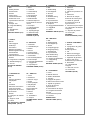
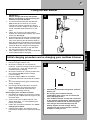
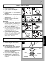
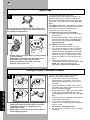
(GB)
(D)
(F)
(NL)
®
INSTRUCTION MANUAL
BEDIENUNGSANWEISUNG
MANUEL D’UTILISATION
GEBRUIKSAANWIJZING
(N)
(SF)
(S)
(DK)
BRUKSANVISNING
KÄYTTÖHJE
BRUKSANVISNING
BRUGSANVISNING
D
WICHTIGE INFORMATION
Bitte vor dem Benutzen des Gerätes
durchlesen und gut aufbewahren
F
RENSEIGNEMENTS IMPORTANTS
A lire avant usage et à conserver pour
référence ultérieure
NL
BELANGRIJKE INFORMATIE
Leest u deze informatie voor het
gebruik en bewaar ze voor
toekomstige raadpleging
N
VIKTIG INFORMASJON
Les bruksanvisningen nøye før bruk
og oppbevar den for senere bruk
SF
TÄRKEÄÄ TIETOA
Lue tämä ennen käyttöä ja säilytä
myöhempää tarvetta varten
S
VIKTIG INFORMATION
Läs anvisningarna före användningen
och spara dem för framtida behov
VIGTIGE OPLYSNINGER
DK Du bør læse brugsanvisningen før
brug og gemme til senere henvisning
E
INFORMACIÓN IMPORTANTE
Léase antes de utilizar y consérvela
como referencia en el futuro
P
INFORMAÇÕES IMPORTANTES
Leia antes de utilizar e guarde para
consulta futura
I
INFORMAZIONI IMPORTANTI
Leggere prima dell’uso e conservare
per ulteriore consultazionez
MANUAL DE INSTRUCCIONES
INSTRUÇNÕES PARA O USO
ISTRUZIONI PER L’USO
IMPORTANT INFORMATION
Read before use and retain for future
reference
(E)
(P)
(I)
GB
GB - CONTENTS
1. Bolt
2. Steady Handle
3. Handle Knob
4. Screws
5. Fixing Plugs
6. Instruction Manual
7. Guarantee Card
8. Flymo/Partner Service
Directory
9. Scraper Tool
10. Integrated Battery
Charger
11. Wall Bracket
12. Guard
ENGLISH PAGES (2-9)
D - INHALT
1. Bolzen
2. Führungsgriff
3. Griffknopf
4. Schrauben
5. Befestigungsdübel
6. Bedienungsanweisung
7. Garantiekarte
8. Flymo/PartnerKundendienstverzeichnis
9. Kratzer
10. Integriertes Ladegerät
11. Wandbefestigung
12. Schutz
DEUTSCHE SEITEN
(10-17)
F - CONTENU DU
CARTON
1. Vis
2. Poignée auxiliaire
3. Vis papillon
4. Vis
5. Chevilles
6. Manuel d’Instructions
7. Carte de garantie
8. Répertoire de Service
Flymo/Partner
9. Racloir
10. Chargeur de batterie
intégré
11. Support mural
12. Carter
LES PAGES EN LANGUE
FRANÇAISE (18-25)
NL - INHOUD
1. Bout
2. Handvat
3. Handvatknop
4.Schroeven
5. Muurpluggen
6.Handleiding
7.Garantiekaart
8.Adressenlijst met
Flymo/Partner Servicecentra
9. Schraper
10. Geïntegreerde
Batterijoplader
11. Ophangbeugel
12. Beschermkap
NEDERLANDSE
PAGINA’S (26-33)
N - INNHOLD
1. Festebolt
2. Håndtaksbøyle
3. Mutter
4. Skruer
5. Festepropper
6. Bruksanvisning
7. Garantikort
8. Servicestasjonsliste
9. Plast Skrape
10. Integrert Batterilader
11. Veggholder
12. Sprutskjerm
NORSKE SIDER (34-41)
SF - SISÄLTÖ
1. Pultti
2. Etukahva
3. Kahvan nuppi
4. Ruuvi
5. Kiinnitystulpat
6. Käyttöopas
7.Takuukortti
8.Flymo/Partnerpalveluopas
9. Kaavin
10. Laturi
11. Seinäteline
12. Suojus
SUOMALAISET SIVUT
(42-49)
S - INNEHÅLL
1. Bult
2. Stödhandtag
3. Handtagsratt
4. Skruvar
5. Pluggar
6. Bruksanvisning
7. Garantikort
8. Flymo/Partners
serviceinformation
9. Skrapare
10. Inbyggd Batteriladdare
11. Väggfäste
12. Sköld
SVENSKA SIDOR (50-57)
DK - INDHOLD
1. Bolt
2. Støttehåndtag
3. Håndtagsknop
4. Skruer
5. Fastgøringsprop
6. Brugsvejledning
7. Garantibevis
8. Flymo/Partner
servicetelefonbog
9. Skrabeværktøj
10. Integreret batterilader
11. Vægophæng
12. Skærm
DANSKE SIDER (58-65)
E - CONTENIDO
1. Perno
2. Manilla del asa
3. Gatillo del Manillar
4. Tornillos
5. Espigas de fijación
6. Manual de instrucciones
7. Tarjeta de garantía
8. Guía de Servicio
Flymo/Partner
9. Herramienta de raspar
10. Cargador de batería
integral
11. Escuadra de pared
12. Guarda
PAGINAS EN
CASTELLANO (66-73)
P - LEGENDA
1. Parafuso
2. Pega fixa
3. Fêmea do parafuso da
pega
4. Parafusos
5. Buchas de fixação
6.Manual de Instrucções
7.Cartão de garantia
8.Lista de Serviços da
Flymo/Partner
9. Ferramenta para raspar
10. Carregador de bateria
integrado
11. Suporte de parede
12. Protecção
PÁGINAS
PORTUGUESAS (74-81)
I - INDICE CONTENUTI
1. Bullone
2. Impugnatura di guida
3. Manopola
dell’impugnatura
4. Viti
5. Maschi di fissaggio
6. Manuale di istruzioni
7. Tagliando di garanzia
8. Elenco dei centri
assistenza Flymo/Partner
9. Raschietto
10. Caricabatterie
integrato
11. Mensola a muro
12. Protezione
ITALIANO (82-89)
1
(N)
KARTONGEN
INNHOLDER
KARTONINHALT
(SF)
PAKETIN SISÄLTÖ
(F)
CONTENU DU CARTON
(S)
(NL)
INHOUD
FÖRPACKNINGENS
INNEHÅLL
(DK)
KARTONINDHOLD
(GB)
CARTON CONTENTS
(D)
A
(E)
CONTENIDO DEL
CARTON
(P)
LEGENDAS DOS
DESENHOS
(I)
CONTENUTO
1
2
3
12
4
5
6
11
10
7
9
8
2
If not used properly this trimmer can be dangerous! This trimmer can cause
serious injury to the operator and others, the warnings and safety instructions
must be followed to ensure reasonable safety and efficiency in using this trimmer.
The operator is responsible for following the warning and safety instructions in
this manual and on the trimmer.
Explanation of Symbols
on the Cordless Trimmer
(GB) SAFETY
Warning
Read the user instructions
carefully to make sure you
understand all the controls and
what they do.
360º
10m
Keep others, including children,
pets and bystanders outside the
10 metre hazard zone. Stop the
trimmer immediately if you are
approached.
The use of eye protection is
recommended to protect against
objects thrown by the cutting line.
General
1. Never allow children or people unfamiliar
with these instructions to use the trimmer.
Local regulations may restrict the age of the
operator.
2. Only use the trimmer in the manner and for
the functions described in these
instructions.
3. Never operate the trimmer when you are
tired, ill or under the influence of alcohol,
drugs or medicine.
4. The operator or user is responsible for
accidents or hazards occurring to other
people or their property.
Battery
Cordless Battery Powered Products
require special care.
1. AVOID ACCIDENTAL STARTING
KEEP HANDS AND FINGERS AWAY
FROM THE SWITCH LEVER WHILE
CARRYING THE TRIMMER.
2. Always charge the product indoors and
store in a cool dry place - out of the reach
of children.
3. Use only the charger provided with your
unit. Use of any other charger could
permanently damage the battery and the
trimmer.
4. Use the charger with standard domestic
household electrical outlets only.
5. Do not abuse the charger or charger cord.
6. Do not use the charger if the charger or
charger cord is damaged.
7. Use the charger indoors only.
8. Do not use the charger outdoors.
9. Store and charge this unit in a cool, dry well
ventilated location and out of the reach of
children.
10. Do not charge the battery or use the unit in
an explosive or corrosive environment.
Avoid areas where flammable liquids or
gases are present to avoid creating a fire or
explosion.
11. Do not attempt to repair the unit including
the battery. Nylon line replacement and
cleaning the unit are the only items suitable
for user maintenance.
3
Battery Care
1. If over a period of time the battery quickly
runs down after a full 24 hour charging
period, a replacement battery is needed.
2. There will be some charge present in the
battery but to ensure maximum running
time, recharge your trimmer for 24 hours
before use.
3. Permanent connection to the charger in a
well ventilated area will automatically keep
your battery fully charged ready for use.
4. To prevent permanent battery damage,
never store in a discharged condition.
5. Contact your local approved service
centre/dealer/distributor for a replacement
battery and for safe disposal of your old
battery .
6. Battery
12 Volt 5 Amp/Hour
"High Power"
Sealed for Life
No maintenance required
•
IMPORTANT
DISPOSE OF YOUR OLD BATTERIES
SAFELY
DO NOT CUT OPEN, BURN OR
INCINERATE.
Battery Replacement
Should your battery need to be replaced contact
your local approved service centre or dealer
who will remove your old battery and fit a
genuine Flymo replacement battery.
•
IMPORTANT
The red lead should always be connected
to the red terminal on the battery. The
black lead should always be connected to
the black terminal on the battery.
Bench Top Re-charging
The wall bracket can also be used as a "bench
top" stand for re-charging your cordless
trimmer.
Winter Storage
1. Fully charge for 24 hours before winter
storage.
2. If you are unable to leave your cordless
trimmer on permanent charge, re-charge
the battery every 3 to 4 months for a full 24
hour charging period to top up the battery
charge during winter storage.
3. Avoid extended storage without re-charge.
4. Store in a cool dry place.
(GB) SAFETY
12. Do not insert any object into the motor area.
Keep free of debris to avoid overheating.
13. Do not incinerate or mutilate the battery.
Batteries contain hazardous chemicals.
Dispose of properly.
Preparation
1. Do not trim barefoot or in open sandals.
Always wear suitable clothing, gloves, and
stout shoes.
2. Inspect the trimmer before each use,
especially the parts of the cutting head.
3. Inspect the area to be cut before each use.
Remove all objects such as stones, broken
glass, nails, wire, string etc, which can be
thrown or become entangled in the trimmer
head.
Use
1. Use the trimmer only in daylight or good
artificial light.
2. Avoid operating your trimmer in wet grass,
where feasible.
3. Take care in wet grass, you may lose your
footing.
4. On slopes, be extra careful of your footing
and wear non-slip footwear.
5. Do not walk backwards when trimming, you
could trip.
6. Switch off before pushing the trimmer over
surfaces other than grass.
7. Never operate the trimmer with damaged
guards or without guards in place.
8. Always start the trimmer carefully with feet
well away from the cutting head.
9 Keep cutting head below waist level
10. Do not lean over the trimmer guard whilst
trimming or edging - objects may be thrown
by the cutting line.
11. Beware of cut-off pieces of nylon line
ejected during use.
Maintenance and storage
1. Keep all nuts, bolts and screws tight to be
sure the trimmer is in safe working
condition.
2. Replace worn or damaged parts for safety.
3. Only use the replacement cutting line
specified for this product.
4. To avoid the risk of injury keep fingers and
hands clear of the line cutter on the leading
edge of the guard.
5. Clean unit with a dry cloth. Never use metal
objects to clean the unit.
4
Product Rating Label
B
Product Number . . . . . . . . . . . . . . . . .
Every Flymo product is uniquely identified by
a silver and black product rating label.
To ensure you have full product information
when obtaining spares or advice from one of
our approved service centres, or if you need
to contact Flymo/Partner's own customer
service department, you should make a note
in the space provided of the information
shown in fig.B. It will also be useful to make
a note of the date and place of purchase
before you return your guarantee card.
Model Number . . . . . . . . . . . . . . . . . . .
Serial Number . . . . . . . . . . . . . . . . . . .
(GB) ASSEMBLY
Date of Purchase . . . . . . . . . . . . . . . . .
Place of Purchase . . . . . . . . . . . . . . . .
•PLEASE KEEP PROOF OF PURCHASE•
Assembly Instructions
C
4
3
2
1
D
E
F
Safety Guard Assembly (C), (D), (E & F)
1. Locate the safety guard (C1) over the
cutting head (C2). Ensure the nylon line
is fed through the hole in the safety
guard as illustrated in fig C.
2. Align the arrow on the top of the safety
guard (C3) with the arrow on the side of
the trimmer (C4). See figs C & D.
3. Push into location and turn safety guard
anti-clockwise, as illustrated in Fig D until
a click is heard and the safety guard is
securely locked in position. See fig E.
•
ENSURE THE SAFETY GUARD IS
SECURELY IN PLACE BY ATTEMPTING
TO TWIST GUARD.
See fig F.
5
Fitting the wall bracket
•
1.
2.
3.
4.
5.
G
1
2
Initial charging procedure and re-charging your cordless trimmer
Initial Charging Procedure
1. Use the charger indoors only.
2. Ensure the charger is not exposed to
moisture. Keep the charger and the trimmer
dry at all times. Keep the charger well
ventilated during charging.
3. Ensure the trimmer is correctly located into
the wall bracket (G2) and the charge
connector (H1).
4. Plug the charger (G1) into a suitable
household electrical wall socket and switch
on.
5. The red indicator lamp glows continuously
during charging.
6. Full charge will be achieved in 24 hours.
During charging the charger becomes
warm. This is normal and means the
charger is operating correctly.
Re-Charging Your Cordless Trimmer
1. Re-charge the battery as soon as the cutting
power of your cordless trimmer begins to die
and slow down.
2. Avoid running the cordless trimmer into
"deep" discharge, i.e. avoid flattening the
battery completely.
3. Follow the procedure outlined in the Initial
Charging Procedure.
4. Charging the battery according to these
instructions should ensure maximum battery
life.
H
1
•
•
•
•
The battery should be charged for 24 hours
before use.
Re-charge your cordless trimmer
immediately after every use for the full 24
hour charging period.
The cordless trimmer can be left connected
to the charger permanently, with the charger
switched on, without fear of overcharging.
The charger will automatically keep the
battery topped up with charge during
storage and will ensure that the cordless
trimmer is ready for use.
(GB) ASSEMBLY
IMPORTANT !
Switch charger off at the wall socket
before connecting or disconnecting the
trimmer to the wall bracket.
It is recommended that the wall bracket
(G2) should be mounted on a smooth,
vertical and internal wall which is strong
enough to hold the weight of the product, in
a well ventilated area between 5°C and
25°C.
There are 3 holes on the wall bracket.
Position the wall bracket with the two holes
at the top. See Fig H.
Ensure that when the trimmer is attached the
bottom of the trimmer is within 4 inches (100
mm) of the ground, this will make it easier to
hang the trimmer and will also ensure that the
wall bracket is within easy reach of an electric
socket to allow the charger to be plugged in.
Fix wall bracket securely to the wall with
the plugs and screws provided.
Your cordless trimmer can now be attached
to the wall bracket for charging.
6
Handle Adjustment
I
bolt
handle
knob
(GB) ADJUSTMENT
J
1.
Attach steady handle to product using bolt
and handle knob as shown in Fig I.
2.
Adjust the steady handle to a comfortable
operating position, see Fig J., by
unscrewing the handle knob, springing the
side lugs apart, moving the handle to the
required position, carefully re-engaging the
teeth and then tightening the handle knob.
See Fig K.
K
Auto Line Feed System
How the automatic line feed works (L)
L
1.
A short length of new line is fed out every
time you switch on, this is caused by the
cutting head accelerating up to its full
speed.
2.
To feed more line, it is necessary to switchoff, allow the motor to stop and then restart.
When edging do this frequently.
3.
When the line feeds you will hear a change
in the motor sound as well as the noise
generated by the line being cut to its length.
4.
If the line does not feed see Fault Finding
Hints for further information.
line cutter
7
How to trim and edge
To start your trimmer
1. Hold as illustrated in Fig M.
2. To start, press lock-off button (M1),
squeeze the switch lever (M2), release
lock-off button.
How to trim
1. Cut with nylon line at an angle using the tip.
See Fig N
2. Swing trimmer in and out of the cutting area
taking small cuts (O)
3. Line is fed out automatically every time the
trimmer head stops rotating and returns to
operating speed.
•
Extra line can be fed out manually as
described on page 8.
4. To stop your trimmer release the switch
lever (M2).
How to edge
1. To convert to edging mode, depress locking
button and twist head anti-clockwise until
arrow lines up with "EDGE". An audible
"click" will confirm that the head is locked.
Ensure the button has returned to its
original position. See Fig P.
2. Rest edger on roller for extra stability and
line up with edge of lawn. See Fig R. Edge
in direction indicated in Fig Q. so that
debris is thrown away from you.
3. To return to trimming mode, depress
locking button and twist head clockwise
until arrow lines up with "TRIM". An audible
"click" will confirm that the head is locked.
Ensure the button has returned to its
original position. See Fig S.
1
M
N
2
O
P
Q
R
S
To remove spool cap
1. Press and hold in the two cap release
latches. See Fig T.
2. Pull cap away from the cutting head. See
Fig U.
When refitting the spool cap
1. Keep all areas of the cap and spoolholder
clean. Failure to do so may prevent the
cap being securely located in the
spoolholder.
2. Align the two latches on the cap with the
two windows in the spoolholder, then press
down into the locked position.
3. Ensure the two cap release latches are
clearly visible and are fully engaged with
the windows in the spoolholder.
4. Check that the cap is correctly fitted by
trying to remove it without depressing the
two latches.
T
cap
release
latches
U
cap
spool
spoolholder
manual line
feed button
eyelet
(GB) USE
Spool Cap
8
Nylon Line
V
Do not depress the button more than three times.
Excessive line will snag the line cutter and cause
the trimmer to malfunction.
W
X
eyelet
hole in
spool
•
•
line
Ensure spool is fully located by gently rotating
it during fitment.
Remember ! Your Flymo Cordless Trimmer is
designed to use only nylon line with a
maximum diameter of 1.5mm. Use only
genuine Flymo nylon line.
To manually feed the nylon line
If required, line can be fed out manually. To
operate, gently pull on the line whilst at the
same time alternately pressing and releasing
the button, on the side of the spoolholder. See
fig V.
To replace nylon line. Replacement nylon line
is available from most Flymo/Partner stockists.
You can buy it either as spool and line
complete, or as nylon line only.
To replace spool and line (complete)
1. Take new spool and remove tape holding
line in place.
2. Unwind approximately 100mm of line and
feed this through eyelet, see fig W, then
drop the spool into spoolholder smooth
side uppermost.
To replace nylon line on spool.
1. Take line and insert into hole in spool.
2. Turn spool clockwise to wind on required
amount of line, (approx. half = 10m) and
cut line to length, see fig X. Care should
be taken to ensure that the line is neatly
coiled on the spool. Failure to do so will
impair the efficiency of the automatic line
feed.
3. Leave approximately 100mm of line
unwound and feed this through eyelet, see
fig W, then drop the spool into the
spoolholder smooth side uppermost.
Caring for your Cordless Trimmer
(GB ) MAINTENANCE
Y
•
•
1
2
3
4
Avoid accidental starting. Keep your hands
and fingers away from the switch lever while
inspecting, cleaning or carrying out any
maintenance work.
Keep fingers and hands clear of line cutter on
leading edge of guard.
After you have finished using your Flymo
trimmer follow the procedure below:
1. Never clean your trimmer with water,
cleaning fluids, or solvents, just remove
debris with a suitable tool, a soft brush or
dry cloth.
2. Using the scraper provided, clean around
the inside of the safety guard to remove any
grass and debris. (Fig Y1)
3. Using a soft brush, clean around the inside
of the safety guard (Fig Y2), the cutting
head (Fig Y3) and the motor housing. (Fig
Y4)
4. Inspect the trimmer carefully, especially the
parts of the cutting head.
5. If your trimmer is damaged in any way
contact your local Flymo/Partner approved
service centre.
•
Never use a damaged trimmer
6. Store in a cool, dry place and out of reach
of children.
9
Guarantee, Fault Finding Hints, Service Recommendations &
Certificate of Conformity
Guarantee & Guarantee Policy
If any part is found to be defective due to faulty
manufacture within one year of original purchase,
Flymo/Partner, through its Authorised Service Repairers will
effect the repair or replacement to the customer free of
charge providing:
(a) The fault is reported directly to the Authorised
Repairer.
(b) Proof of purchase is provided.
(c) The fault is not caused by misuse, neglect or faulty
adjustment by the user.
(d) The failure has not occurred through fair wear and
tear.
(e) The machine has not been serviced or repaired, taken
apart or tampered with by any person not authorised
by Flymo/Partner.
(f)
The machine has not been used for hire.
(g) The machine is owned by the original purchaser.
(h) The machine has not been used outside of the country
for which it was specified.
(i)
The machine has not been used commercially.
*
This guarantee is additional to, and in no way
diminishes the customers statutory rights.
Failures due to the following are not covered, therefore it is
important that you read the instructions contained in this
Operator's Manual and understand how to operate and
maintain your machine:
Failures not covered by guarantee
*
Replacing Nylon Line.
*
Failures as a result of not reporting an initial fault.
*
Failures as a result of sudden impact.
*
Failures as a result of not using the product in
accordance with the instructions and
recommendations contained in this Operator's Manual.
*
Machines used for hire are not covered by this
guarantee.
*
The following items listed are considered as wearing
parts and their life is dependent on regular
maintenance and are, therefore not normally subject to
a valid warranty claim: Nylon Line, Electric Mains
cable.
*
Caution!
Flymo/Partner does not accept liability under the
warranty for defects caused in whole or part, directly
or indirectly by the fitting of replacement parts or
additional parts that are not either manufactured or
approved by Flymo/Partner, or by the machine having
been modified in any way
Fault Finding Hints
1.
Line too short
Manually feed out the line.
2.
Line broken inside cutting head
Remove cap and re-thread line.
3.
Line jammed on spool
Remove cap and spool and rewind line to remove crossed
loops.
4.
Excess line feed
Battery needs to be charged.
5.
Poor performance
Ensure inside of cutting head housing is clean and free from
debris.
6.
Trimmer stops during use
Release switch lever and wait 30 seconds before re-starting.
Service Recommendations
To ensure the maximum life and reliability from your Flymo product
we recommend that it is serviced regularly by an approved
Flymo/Partner Service Centre/Dealer. They have the equipment
facilities and trained personnel to advise you on the service
requirements of your machine. Depending on the machine's use
they will recommend one of the various types of service which are
designed to ensure the maximum economic service life of your
machine.
Certificate of Conformity
Signed at
NEWTON
AYCLIFFE..................................................
1998
I, the undersigned P. Howells of
Flymo/Partner, a Division of Electrolux
Outdoor Products Limited, Aycliffe
Industrial Estate, NEWTON AYCLIFFE,
Co. Durham. DL5 6UP. Certify that a
sample of the above product has been
tested using directive 81/1051/EEC as a
guide. The maximum A-weighted sound
pressure level recorded at operator
position under free field semi anechoic
chamber conditions was :-
I, the undersigned P. Howells of
Flymo/Partner, a Division of Electrolux
Outdoor Products Limited, Aycliffe
Industrial Estate, NEWTON AYCLIFFE, Co.
Durham. DL5 6UP. Certify that a sample
of the above product has been tested
using ISO 5349 as a guide. The maximum
weighted root mean square value of
vibration recorded at operator’s hand
position was:-
Type
MCT-250
Type
MCT-250
Identification of Series
See Product Rating
Label
Identification of Series
See Product Rating
Label
Level
77.2 dB(A)
Value
1.6 m/s2
Signed at
NEWTON
AYCLIFFE...................................................
1998
Signed at
NEWTON
AYCLIFFE.................................................
1998
(GB ) MAINTENANCE
I, the undersigned P. Howells of
Flymo/Partner, a Division of Electrolux
Outdoor Products Limited, Aycliffe
Industrial Estate, NEWTON AYCLIFFE,
Co. Durham. DL5 6UP. Certify that a
sample of the above product has been
tested and found to comply with
directives:89/392/EEC, 89/336/EEC, 73/23/EEC
Certificate of Conformity / Certificat de Conformite
I, THE UNDERSIGNED/JE SOUSSIGNÉ: P. HOWELLS OF FLYMO/PARTNER, A DIVISION OF
ELECTROLUX OUTDOOR PRODUCTS LIMITED, AYCLIFFE INDUSTRIAL ESTATE, NEWTON
AYCLIFFE, COUNTY DURHAM DL5 6UP ENGLAND
Certify that the Trimmer/Atteste que le taille-herbe
1.
2.
Category/Categorie . . . . . . . . . . . . . . . . . . . . . . . . . . . . . . . . . . . . . . . Electric
Make/Marque . . . . . . . . . . . . . . . . . . . . . . . . . . . . . . . . . . . . . . . . . . . . Flymo
Conforms to the specifications of Directive 84/538/EEC/
Conforme aux specifications de la directive 84/538/CEE
Type of Cutting Device / Genre du dispositif de coupe . . . . . . . . . . . . . . Nylon Line
TYPE
Identification of Series / (No. de Serie)
Engine/Moteur- Manufacturer/Fabriquant
MCT250
SEE PRODUCT RATING LABEL/
VOIR ETIQUETTE SIGNALÉTIQUE DU
PRODUIT
Johnson HC785LG
Cutting System Width/ Largeur de coupe
25 cm
Speed of Rotation of Cutting Device/
Vitesse de rotation du dispositif de coupe
9,400 RPM
Tested by (laboratory)/
Examine par (reference du laboratoire)
Ricardo
Guaranteed sound power level/
Niveau de puissance acoustique garanti
91 dB(A)
Signed at/fait a
NEWTON AYCLIFFE
Date 1998 . . . . . . . . . . . . . . . . . . . . . . . . . . . . . . . . . . . . . . . . . . . . . . . . . . . .
Flymo/Partner, a division of Electrolux Outdoor Products Ltd.,
Aycliffe Industrial Estate
NEWTON AYCLIFFE
Co.Durham DL5 6UP
ENGLAND
Telephone - (00) 44 1325 300303 Fax - (00) 44 1325 310339
UK Telephone - 01325 300303 Fax - 01325 310339
Our policy of continuous improvement means that the specification of products may be altered from time to time
without prior notice. Flymo/Partner, a division of Electrolux Outdoor Products Ltd. manufacture products for a
number of well known brands under various registered patents, designs and trademarks in several countries.
© Electrolux Outdoor Products Ltd. Registered Office, Electrolux Works, Oakley Road, Luton LU4 9QQ
Registered number 974979 England
5118562-02