1
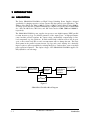
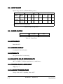
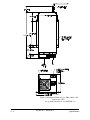
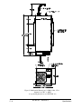
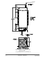
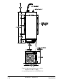
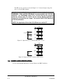
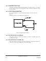
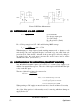
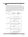
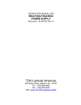
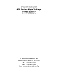
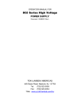
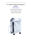
INSTRUCTION MANUAL FOR
83-493-001 Revision G
MODEL
SERIAL NUMBER
405 ESSEX ROAD, NEPTUNE, NJ 07753
TEL: (732) 922-9300
FAX: (732) 922-9334
Table of Contents
1 INTRODUCTION
1.1 Description
2 SPECIFICATIONS
2.1 Average Charging Rate
2.2 Peak Charging Rate
2.3 Number of Models in Series
2.4 Standard Voltage Ranges
2.4.1 Linearity
2.4.2 Accuracy
2.5 Polarity
2.6 High Voltage Assembly
2.7 Input Connector
2.8 Input Chart
2.9 Power Factor
2.10 Efficiency
2.11 Stored Energy
2.12 Stability
2.13 Pulse To Pulse Repeatability
2.14 Temperature Coefficient
2.15 Ambient Temperature
2.16 Humidity
2.17 Protection
2.18 Agency Approvals
2.19 Transient Line Protection
2.20 ESD
2.21 Note for PFC Units
2.22 Accessories
2.23 Options
2.23.1 Suffix -SYS
2.23.2 Suffix -RFI
2.23.3 Suffix -LH
2.23.4 Suffix -EN
2.23.5 Suffix -5V
2.23.6 Suffix -LP
2.23.7 Suffix -110
2.24 Orientation
3 INSTALLATION
3.1 Initial Inspection
3.2 Mounting and Cooling Requirements
3.3 Input AC Power
3.4 Power Cord Specification:
3.5 Connecting High Voltage Output
3.6 Grounding the Product
3.6.1 Grounding of Input Line
3.6.2 Output Ground Connection
3.6.3 For Units with O/P Voltage £6KV
3.6.4 For Units with O/P Voltage > 6KV:
4 OPERATION
4.1 Remote Control
1-1
1-1
2-1
2-1
2-1
2-1
2-1
2-1
2-1
2-1
2-1
2-1
2-2
2-2
2-2
2-2
2-2
2-2
2-2
2-2
2-3
2-3
2-3
2-3
2-3
2-3
2-3
2-3
2-3
2-3
2-3
2-4
2-4
2-4
2-4
2-4
3-1
3-1
3-1
3-1
3-2
3-3
3-3
3-3
3-4
3-4
3-4
4-1
4-1
83-493-001 Revision G
i
Table of Contents
4.2 Initial Check-Out Procedure
5 APPLICATIONS
5.1 Determining Capacitor Charge Time
5.2 Voltage Reversal
5.3 Paralleling Units
5.4 Measuring High Voltages
5.5 Determining AC Line Current
5.6 Continuous HV DC Operation (Constant Voltage)
5.7 Long Charge Time With Power Factor Corrected (PFC) Units
6 MAINTENANCE AND CALIBRATION
6.1 Safety Precautions
6.2 Maintenance
6.3 Calibration
4-3
5-1
5-1
5-1
5-2
5-3
5-4
5-4
5-5
6-1
6-1
6-1
6-1
List of Figures
Figure 1.1 152A Block Diagram
Figure 2-1 Mechanical Dimensions for Units up to 6KV
Figure 2-2 Mechanical Dimensions for Units 7KV to 40KV
Figure 3-1 Input AC Power Connection NON-PFC Version
Figure 3-2 Input AC Power Connection, PFC Version
Figure 3-3 Output Ground Connection
Figure 4-1 Eample Of Interface Connection
Figure 5.1 Output Voltage Waveform
Figure 5.2 Output Current Measurement
Figure 5.3 HV Bias Measurements
Figure 5.4 Long Charge Time Operation
1-1
2-5
2-6
3-2
3-2
3-4
4-2
5-1
5-1
5-4
5-5
List of Tables
Table 2.1 High Voltage Cable
2-1
Table 2.2 Input Voltage Chart
2-2
Table 2.3: Power Factor
2-2
Table 4.1 Control Interface Connection For Standard 500A/102A/152A Series
4-1
Table 5.1 Output Capacitance
5-2
83-493-001 Revision G
ii
Table of Contents
The Series 500A/102A/152A/202A are High Voltage Switching Power Supplies designed
specifically for charging capacitors in laser systems and other pulsed power applications. The
500A provides 500 J/s, the 102A is 1000 J/s, 152A is 1,500 J/s, and the 202A provides 2000 J/s
of average power and can be paralleled indefinitely for higher total system power. Lambda EMI
also offers the 402 Series, 802 Series, and 303 Series rated at 4,000, 8,000 and 30,000 J/s
respectively.
The 500A/102A/152/202A power supplies incorporate a new high-frequency IGBT parallel
resonant inverter topology for efficient generation of the output power. A high-performance
control module precisely regulates the output voltage, automatically compensating for line,
load, temperature, rep rate variations. Normal external fault conditions such as line dropout,
open or short circuit load, HV arc and over-temperature will not damage the unit. The latest
development in the parallel resonant inverter topology and control circuitry also drastically
improves pulse-to-pulse repeatability by reducing the ripple or "bucket effect" even at very high
pulse repetition frequencies. The output voltages of the 500A/102A/152A/202A supplies are
fully adjustable over each range.
INPUT/POWER
PFC / Fuses
Inrush Limit
High Freq.
Resonant
Inverter
Step-up
Transformer
HV Rect.
HV Filter
HV OUTPUT
Control
&
Aux. Power
Figure 1.1
500A/102A/152A/202A Block Diagram
83-493-001 Revision G
1-1
Introduction
500J/s, 1000J/s, 1500J/s 2000J/s at rated Output Voltage
550J/s, 1100J/s, 1650J/s 2200/J/s at rated Output Voltage
12 Standard (others at extra cost)
1kV, 1.5kV, 2kV, 3kV, 4kV, 5kV, 6kV, 10kV, 15kV, 20kV, 30kV, 40kV. All models
continuously variable from 0 to 100% of rated output voltage.
2.4.1 LINEARITY
Linear to within 1% of full scale.
2.4.2 ACCURACY
1% of rated.
Available as fixed Positive or Negative
Insulating Medium/Cable
Voltage
Medium
Output Cable
1kV to 6kV
Air
Coax. RG58
10kV to 40kV
Oil
12 AWG, HV Silicon
Table 2.1 High Voltage Cable
! VDE, UL approved.
83-493-001 Revision G
2-1
Specifications
" Input Voltage selective by Terminal Block position
Input Voltage (VAC)
Current (No PFC)
Non PFC
Current (PFC)
500A 102A 152A
202A
500A
102A
152A 202A
Nameplate
Range
Design
Range
200-220
50/60Hz
180-240
50/60Hz
5A
10A 14.5A
--
3.5A
6.6A
10A
13.5
100-120
50/60Hz
90-140
50/60Hz
10A
20A
--
7A
--
--
--
30A
*Note: Input current ratings given are maximum when output Repetition Rate is =>10Hz. Consult
Factory if model used at less than 10Hz.
Table 2.2 Input Voltage Chart
# All models
Non PFC
PFC
0.65
0.98
Table 2.3: Power Factor
Better than 85%
Less than 0.3 Joules all models
0.2% per hour after 1 hour warm-up.
±0.2% to 300 Hz. For higher repetition rates, consult factory
100ppm per °C
Storage -40 to +85°C. Operating -20 to +45°C
83-493-001 Revision G
2-2
Specifications
90%, non-condensing
! The power supply is protected against Open Circuits, Short Circuits, Overloads and Arcs
" 500A/102A/152A are approved to UL2601 and TUV 601-1. Class I, per IEC 601-1. 202A
pending approvals.
# Meets requirements of IEC 801-4, 801-5
All Remote Control Functions meet requirements of IEC 801-2
When High Voltage is enabled by using either the "HV Enable" Line or deactivation of the
"Inhibit" Line the power supply will reach normal operation mode (and therefore all other
published specifications) within 50 ms.
Detachable 8 feet (2.4 meters) HV Cable (see Table 2.1)
15 pin 'D' plug mating control connector
Operating Manual
2.23.1 SUFFIX -SYS
Parallel Operation
2.23.2 SUFFIX -RFI
Optional external fit on filter which reduces conducted Electro-Magnetic Emissions.
Approved VDE0871/6.78 Class B.
2.23.3 SUFFIX -LH
"Low Inhibit" - A +10 to 15 volt (high) signal will allow power supply operation. A 0 to
+1.5 volt (low) signal will inhibit the supply.
83-493-001 Revision G
2-3
Specifications
2.23.4 SUFFIX -EN
"Low Enable" - A +10 to 15 volt (high) signal will disable power supply operation. A 0 to
+1.5 volt (low) signal will enable the supply.
2.23.5 SUFFIX -5V
0 to +5 volt voltage (0 to full-scale output) programming
2.23.6 SUFFIX -LP
Latching overload protection.
2.23.7 SUFFIX -110
100 to 120 VAC input option for non-power factor corrected 152A (1500 J/s) model.
NOTE: 152A power supply with suffix 110 at 100-120VAC
must be operated with internal 20A fuses F1 & F2 (on inverter bd)
replaced by copper bus provided with the supply. Use external
30A UL/VDC approved fuse/circuit breaker.
Power supplies >6kV with Oil H.V. section must be operated in upright position. i.e. The
mounting bracket is parallel to the ground plane.
83-493-001 Revision G
2-4
Specifications
Figure 2-1 Mechanical Dimensions for 500A, 102A, 152A
Outputs up to 6KV
(for grounding instructions see SECTION 3.6)
83-493-001 Revision G
2-5
Specifications
Figure 2-2 Mechanical Dimensions for 500A, 102A, 152A
Outputs from 7KV to 40KV
(for grounding instructions see SECTION 3.6)
83-493-001 Revision G
2-6
Specifications
Figure 2-3 Mechanical Dimensions for 202A
Outputs up to 6KV
(for grounding instructions see SECTION 3.6)
83-493-001 Revision G
2-7
Specifications
Figure 2-4 Mechanical Dimensions for 202A
Outputs from 7KV to 40KV
(for grounding instructions see SECTION 3.6)
83-493-001 Revision G
2-8
Specifications
The shipping container should contain the following items: power supply, HV output cable,
male 15-pin "D" remote control connector and operator's manual. Examine the items
immediately for damage. Locate the serial number label on the side of the power supply
and verify the model number, the input voltage rating and the output voltage rating and
polarity. In the event of any damage promptly notify the transportation company and the
Lambda EMI Customer Service Manager.
$
$
The power supply can be mounted by the chassis support brackets (see Figure 2-1 and 2-2
for details). The mounting brackets are attached to the supply. The supply must mounted
using four PHMS 8-32NC X 0.250 screws. Using wrong (longer) screws may short HV
part to ground ,causing permanent damage to power supply. The power supply can also
operate on a bench or table top. Power supplies >6kV with Oil H.V. section must be
operated in upright position i.e. mounting bracket parallel to ground plane. In all
cases adequate clearances must be provided for proper air flow and cable bends. Keep the
minimum HV cable bend radius greater than 4 inches (101.6mm) to minimize stress on the
insulation. Generally, at least 4 inches (101.6mm) of clearance should be allowed at the
inlet of the power supply and 2 inches (50.8mm) at the sides.
When operating in an enclosed system, care must be taken to ensure the ambient inlet air to
the power supply does not exceed the maximum operating temperature of 45°C. This often
requires addition of a system heat exchanger.
Proper grounding from the input AC power is required to reduce the risk of electric shock.
The metal chassis of the power supply is grounded through the green earthing wire at the
input AC power terminal block. A protective ground connection by way of the grounding
conductor in the input terminal is essential for safe operation. Use extreme caution when
connecting input AC power and never apply the incorrect input power. (Figure 2-1 & 2-2).
The PFC version and version without PFC should be connected as explained in the
following 2 paragraphs.
A. Version with no PFC.
For this version, the supply can be connected to either 110VAC or 220VAC input
voltage. (See Table 2.2). These connections are shown in Figure 3-1.
1. For 110VAC connect the input line wires to L1 and COM terminals.
2. For 220VAC connect the input wires to L2 and COM terminals.
B. Version with PFC.
83-493-001 Revision G
3-1
Installation
The PFC version connection is shown in Figure 3-2. Connect the input voltage line
wires to L2 and COM terminals.
WARNING: 152A and 202A PFC Models are only available with 220 VAC
Nominal. For 152A Models Suffix 110 at 110-120 VAC must be operated
with the internal fuses F1 and F2 (on the Inverter Board) replaced by
copper bus provided with the supply. Use external 30A UL/VDC Approved
Fuse/Circuit Breaker.
NOTE: For Application At less than 10 Hz Please see section 5.7.
TB1
L1
110 VAC
COM
220 VAC
L2
Figure 3-1 Input AC Power Connection NON-PFC Version
TB1
L1
COM
VAC
L2
Figure 3-2 Input AC Power Connection, PFC Version
%
%
Use wire with minimum .064 inches (1.6 mm) diameter and 600 V insulation.
83-493-001 Revision G
3-2
Installation
POTENTIAL LETHAL VOLTAGE
Ensure that the power supply is off and disconnected from the input power and
never operate the power supply without a load cap. Make sure that all load
capacitors are discharged and shorted to ground before making any connections.
Lambda EMI recommends the use of safety dump switches in high voltage
discharge circuits.
Never handle the HV cable during operation.
This power supply is designed to operate with a capacitive load. Operation of the
power supply without an external load capacitor may result in damage to internal
circuitry.
Always use the HV connector and cable provided with the power supply or an equivalent
substitute provided by EMI. Fully insert the connector end of the HV cable and tighten the
locking nut only "hand tight".
NOTE: When operating above 20 kV and 200 Hz rep. rate, ensure
that a silicone grease (such as Dow Corning DC-4) is applied
to the HV cable before insertion into the HV connector.
This displaces the air in the connector and reduces long term
corona effects.
Keep the minimum HV cable bend radius greater than 4 inches (101.6mm) to minimize
stress on the insulation. Keep the HV cable as distant as possible from the input power and
the input control signals.
Some peak current will flow out of the power supply during discharge and return through
the HV return and system chassis. This current comes from voltage reversal in
underdamped systems and from normal discharge of filter and cable capacitance. The path
for this current should not parallel control signal returns since the resulting voltages could
interfere with normal system operation. The currents developed with voltage reversal at
high rep. rates, could damage the power supply. A resistor in series with the HV output can
be added to limit this current to an acceptable level. Refer to Section 5.2, Page 15 for more
information.
The oil-filled HV assembly should not be opened. The oil and components have been
specially cleaned and vacuum impregnated at the factory and the assembly hermetically
sealed. Opening the assembly will compromise performance and void the warranty. Tanks
must only be serviced at Lambda EMI.
83-493-001 Revision G
3-3
Installation
3.6.1 GROUNDING OF INPUT LINE
The supply is grounded through the ground terminal of the input connector. A protective
ground connection by the way of the grounding conductor in the input terminal is essential
for safe operation.
3.6.2 OUTPUT GROUND CONNECTION
It is important that there be a ground connecting the supply to the load as shown in
Figure 3-3.
See Figure 2-1 and 2-2, for grounding cable configuration.
Figure 3-3 Output Ground Connection
3.6.3 FOR UNITS WITH O/P VOLTAGE ≤6kV
The ground connection is made via the shield of the RG58 coaxial HV output cable
provided with the supply.
3.6.4 FOR UNITS WITH O/P VOLTAGE > 6kV:
The ground connection between the load and the supply must be made with a separate wire
to the 8-32, 1/2" NC long grounding stud provided on the supply.
83-493-001 Revision G
3-4
Installation
The Series 500A/102A/152A/202A is easily controlled through the remote connector on
the input panel of the unit. Only the ENABLE/RESET, V PROGRAM and GND signals
are required for operation. The remaining signals are provided for status monitoring and
fault diagnosis. A schematic diagram showing the suggested interface circuit is shown in
Figure 4-1. This table is for a standard configuration.
PIN
SIGNAL NAME
I/O
DESCRIPTION
1
ENABLE/RESET
INPUT
A high signal (+10 to 15V) with respect to ground
(pin 14) will enable the power supply. Latching faults
can be cleared by cycling this switch. Ground or open
disables the supply.
5
V PROGRAM
INPUT
A 0-10V signal with respect to ground at this pin
programs the output voltage proportionally from zero to
rated output.
7
VPEAK
8
VANALOG
10
INHIBIT
9, 11
+15V
OUTPUT 15V regulated. Can be used for user programming
applications 20mA max.
14
GND
OUTPUT Control circuit return. Also chassis/earth ground
15
INHIBIT LED
OUTPUT Open collector. Indicates that the power supply is
receiving an INHIBIT signal.
13
EOC LED
3, 6
SUMMARY
FAULT LED
2
LOAD FAULT
OUTPUT A 0-10V signal (with respect to ground) proportional to
the peak of the output charging voltage. Can be used to
drive a meter displaying peak output voltage.
OUTPUT 0-10V analog of output charging voltage waveform.
INPUT
A +10 to 15V with respect to ground, disables the unit.
Open or ground allows operation. This input can be
used to disable charging during HV switch recovery.
OUTPUT Open collector. Indicates that the power supply is
reaching end-of-charge, i.e. the V PROGRAM set point.
OUTPUT Open collector. Indicates an output overvoltage.
Temperature fault or low input voltage condition.
OUTPUT Indicates a shorted O/P or a very large load capacitor.
Table 4.1 Control Interface Connection For Standard 500A/102A/152A/202A Series
83-493-001 Revision G
4-1
Operations
Figure 4-1 Eample Of Interface Connection
83-493-001 Revision G
4-2
Operations
&
&
&
LETHAL VOLTAGES PRESENT
ONLY QUALIFIED PERSONNEL TRAINED IN THE SAFETY ASPECTS OF
HIGH VOLTAGE SHOULD PERFORM INITIAL CHECKOUT PROCEDURES.
The power supply should have no visible damage or defects and the cover should be
securely fastened. Properly connect the input power (Section 3.5), control connector
(Sec. 4.1) and HV output (Sec. 3.5, and 3.6).
If there is no load connected, the power supply will regulate the output voltage to the
programmed voltage level or sense an open circuit and immediately shut down indicating a
FAULT.
If there is a short circuit or overload condition on the output, the power supply will operate
in a 50% duty cycle protection mode and indicate a LOAD FAULT.
An overload condition can occur if the INHIBIT signal is missing, allowing HV switch to
latch-up. It can also occur if the discharge rep. rate is too high to allow the capacitor to
fully charge to V PROGRAM.
Double check all connections and ensure that all personnel are protected from the HV output.
With the VPROGRAM at zero volts, turn the power supply on in the following sequence:
1. Connect power supply to the HV load
2. Increase load rep. rate to prevent a full charge
3. VPROGRAM signal (pin 5) at zero volts.
4. ENABLE/RESET signal (pin 1) at zero volts.
5. Assert ENABLE/RESET signal to 15V.
6. Verify HV output is at approx. zero volts.
7. Increase HV (by increasing VPROGRAM voltage) output slowly and verify adjustability.
8. Decrease load rep rate to allow full charge
83-493-001 Revision G
4-3
Operations
For clarification and further technical assistance specific to your application, please contact
Lambda EMI.
The ratings of these supplies are as follows: 500A - 500 J/s, 102A - 1000 J/s, 152A 1500J/s, 202A-2000J/s average charge rate. Although the measure of Joules/sec equates to
Watts, Stored Energy per unit time is more convenient when working with energy storage
capacitors. The peak charge rate determines the capacitor charge time. The average charge
rate determines the total power delivered from the power supply. It is possible to charge a
capacitor at 1650 J/sec, but to discharge it at a low rep. rate producing an average of 100
J/sec. The following formulas can be used to determine the average and peak charge rate.
VOLTAGE
Tc
Peak Charge Rate =
1
2
2 CV
TC
1
2
2 CV
Average Charge Rate =
Tp
Tp
TIME
C - OUTPUT LOAD CAPACITOR
V - PROGRAMMED OUTPUT VOLTAGE
TC AND TP ARE SHOWN IN FIGURE
Figure 5.1 Output Voltage Waveform
When the capacitor or PFN is discharged, a high peak current may flow out of the power
supply as a result of voltage reversal. This occurs in a system which is underdamped in order
to clear the high voltage switch after each pulse. The average value of this peak current
added to the normal output current may exceed the rating of the HV diodes in the power
supply. This current can be measured with a current transformer as shown in Figure 5.2.
83-493-001 Revision G
5-1
Applications
Figure 5.2 Output Current Measurement
A series terminating resistor (or series inductor or clamp diode) must be added as shown if
the average value of the peak current exceeds 110% of the normal output current.
When choosing Rs, ensure it can withstand the full output voltage across it as well as the
power dissipation caused by discharging Co (see Table 5.1) and Cc (20pF/ft) (65.62 pf/m)
each cycle as well as conducting the normal output current. It's power dissipation can be
calculated as Pd = (I O 2 R S ) + 1/2(C O + C C ) V 2 (REP RATE) .
Output Voltage
Co
1-2.8kV
60nF
3kV-6kV
15nF
10-30kV
460pF
40kV
230pF
Table 5.1 Output Capacitance
The 500A/102A/152A/202A power supplies are designed for simple parallel operation. The
input power and HV output should be connected directly together. The REMOTE
connectors on the input panel can also be connected directly together using a "daisy chain"
ribbon cable from the system controller. Each of the power supplies operate at the same
time with the total charge rate equal to the sum of each.
Sometimes when operating several units in parallel, the high total power generates noise
which interferes with the power supply control. This is usually due to the many
interconnecting control cables acting as an antenna picking up noise. The problem usually
appears as one or more of the power supplies shuts down when the output voltage increases
beyond a certain level. Dressing the control cables as short as possible and close to ground
or using shielded cables should help. In severe cases, it is necessary to wrap the cables
several times through high permeability ferrite cores at the input panel of each unit.
The 500A/102A/152A/202A power supplies can also be used as an Isolated High Voltage
continuous DC power source by adding an external filter capacitor. The value of the filter
capacitor depends upon the value of the allowable output voltage ripple value. For parallel
operation into DC loads, please contact EMI Customer Service Department. (See Section 5.6).
83-493-001 Revision G
5-2
Applications
WARNING: EXTREME CAUTION MUST ALWAYS BE EXERCISED WHEN
TAKING ANY HIGH VOLTAGE MEASUREMENTS. IT SHOULD BE DONE
ONLY BY QUALIFIED PERSONNEL WHO ARE TRAINED IN THE SAFETY
ASPECTS OF WORKING WITH HIGH VOLTAGE.
A sample of the output voltage is available in the REMOTE connector. If it is desired to
measure the HV output externally, care must be taken to understand the accuracy of the
measurement.
When making a DC measurement, such as when the power supply is holding voltage on a
capacitor, any HV probe and DVM combination can be used. The Fluke 80K-40 probe
with any 10M input resistance DVM is adequate up to 40kV. Building a simple resistor
divider using appropriate HV resistors is also very straightforward. Keep in mind that all
HV resistors, including the one in the Fluke probe, exhibit a negative voltage coefficient,
changing by up to 4% from zero to max. voltage. Derating the resistors and calibrating at
the operating point solves this problem.
The value of the resistor R1 and R2 (Figure 5.3) can be calculated as follows:
VM =
R2
V O where VO is the High Voltage being measured.
R1R2
Making a pulsed measurement with an oscilloscope requires a compensated HV probe
having a wide bandwidth. Simply connecting a DC probe, through the proper resistance,
into a scope yields a slow response only adequate for low rep. rate systems. As with DC
probes, the pulsed probe resistor voltage coefficient is a problem. In addition, damage to
the resistors can occur during pulsing due to high electric field gradients. Also, stray
capacitance to nearby objects can significantly alter the pulse response. For a
high-performance, shielded probe to 40KV use a Tektronix P6015 or Ross Engineering
VD60-8.3-A-K-LB.
Measurements accurate to better than 0.1% can be achieved using a bias technique. For
example, if a 40V signal (40kV divided by 1000) is to be measured accurately, the minus input
of the DVM would be biased up 40V. The original signal, with respect to ground, is fed to the
plus input of the DVM. The bias can be measured accurately for absolute measurements, or
relative measurements read directly as the line or load is varied. In the same manner, an
oscilloscope return can be biased for accurate peak measurements during pulsing.
83-493-001 Revision G
5-3
Applications
Figure 5.3 HV Bias Measurements
IL =
P
V L P F EFF
IL = Line current
P = Average output power
VL = Line voltage
PF = Power factor (.65 min)
EFF = 0.85
Ex: A 152A operating from 115V - 10% and delivering 1000W average.
IL =
1000
0.9 = 17.5A
(115)(.65)(0.85)
When charging very large capacitor banks requiring many seconds or minutes to reach
end-of-charge, the power supply will display a load fault and go into a 50% duty cycle
protection mode. If this feature is defeated and the power supply is allowed to charge for
an extended period, the peak output power, not the average power, must be used to
determine line current. (See Section 5.7).
'
(
(
' The 500A/102A/152A/202A supplies can be used as a constant voltage supply by the
addition of an external filter capacitor. The value of this capacitor will determine the ripple
voltage on the DC output.
The value of this ripple voltage can be expressed as :
1.4(Po max)
V PK−PK =
(Vo)(Co)(Fs)
Where : Po max = Maximum outut power in watts
Vo = Output voltage in volts
Co = Total output capacitance in microfarads
Fs = Lowest switching frequency (40KHz)
When operating as a DC supply care must be taken not to draw more than the J/sec rating
of the unit.
Also, if the filter capacitor is inadvertently shorted, it may ring which can damage the
supply (Section 5.2).
83-493-001 Revision G
5-4
Applications
! '(
'(
It is advised that you consult the factory if this type of operation is required.
On supplies with active Power Factor Correction there is a limit to the length of the charge
time. With all capacitor charging supplies, the peak output power capability is twice the
joule per second rating. At pulse rates greater than approximately 20Hz, the internal filter
capacitors can average the power drawn from the power factor correcting circuit. At lower
pulse rates, the output stage will attempt to draw twice the rated average power fro the PFC
circuit. The internal current limit if the PFC circuit will be activated and the supply will
shut down. To avoid this type of fault condition, the output power can be reduced by
providing an inhibit pulse of fixed or variable duty cycle to keep the average output within
the PFC rating (See Figure 5.4).
Figure 5.4 Long Charge Time Operation
83-493-001 Revision G
5-5
Applications
ONLY QUALIFIED PERSONNEL TRAINED IN THE SAFETY ASPECTS OF
HIGH VOLTAGE SHOULD PERFORM CALIBRATION.
The calibration steps described in this section require operation of the power supply with
the cover removed. Proceed with extreme caution as hazardous voltages are exposed
throughout the unit.
Safety glasses must be worn to prevent serious injury in the event of a component failure
(e.g., power transistors readily explode during fault conditions).
Because the power supply does not receive proper cooling with the cover removed, it must
be cooled by an external fan placed next to the supply to cool the inverter and HV section
(min. air flow 100 CFM (2.83 M3/min.)) when operating at full power. Operation at full
power with cover removed should be limited to less than five minutes.
No maintenance is required under normal operating conditions. Occasional vacuum or
blow-out of the chassis may be required when operated in extremely dirty environments.
The oil-filled HV assembly must not be opened. The oil and components have been
specially cleaned and vacuum impregnated at the factory and the assembly hermetically
sealed. Opening assembly will compromise performance and void warranty. HV Tanks
must only be services at Lambda EMI.
Calibration of the output voltage is accomplished with trim pot RP4 located on the control
board. This is the top PC board of the inverter assembly. RP4 is a 25 turn trimpot. Slowly
turn it clockwise to decrease the output voltage for a given VPROGRAM. Factory set for 10V
rated voltage for standard version. Refer to Sections 4.1 and 4.2 of product specification
for Linearity and Accuracy.
83-493-001 Revision G
6-1
Maintenance and Calibration