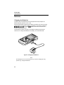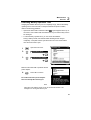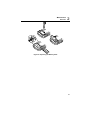
1
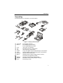
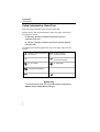
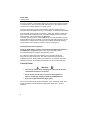
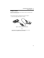
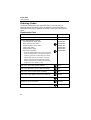
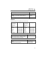
®
Fluke 43B
Power Quality Analyzer
Users Manual
4822 872 30455
April 2001
© 2001 Fluke Corporation, All rights reserved. Printed in The Netherlands.
All product names are trademarks of their respective companies.
Fluke 43B
Users Manual
PLACING ORDERS AND GETTING ASSISTANCE
To locate an authorized service center, visit us on the World Wide Web:
http://www.fluke.com
or call Fluke using any of the phone numbers listed below:
+1-888-993-5853 in U.S.A. and Canada
+31-402-675-200 in Europe
+1-425-446-5500 from other countries
Table of Contents
Chapter
Title
Page
Unpacking .................................................................................... 1
Safety Information: Read First ..................................................... 2
Current Probe.......................................................................... 4
1
Introducing the Fluke 43B .........................................................
Powering the Fluke 43B ...............................................................
Inputs ...........................................................................................
Main Menu ...................................................................................
Instrument Setup..........................................................................
Setting the Date.......................................................................
Setting the Time ......................................................................
Adjusting the Contrast .............................................................
Selecting Probes .....................................................................
Setting up the Harmonic- and Power Function........................
Selecting a Language .............................................................
Using FlukeView Software ...........................................................
Using a Printer .............................................................................
Connecting to a Printer............................................................
Selecting a Printer Type ..........................................................
Resetting the Fluke 43B...............................................................
5
5
7
8
14
14
15
16
17
19
21
22
23
23
24
25
2
Maintenance ...............................................................................
Cleaning and Storage ..................................................................
Cleaning the Fluke 43B ...........................................................
Storing the Fluke 43B..............................................................
Cleaning the Current Probe.....................................................
Batteries .......................................................................................
Charging the Batteries.............................................................
Extending Battery Operation Time ..........................................
Replacing the Ni-Cd Battery Pack...........................................
Ordering Codes............................................................................
Replaceable Parts ...................................................................
Manuals...................................................................................
27
27
27
27
27
28
28
29
30
32
32
33
i
Fluke 43B
Users Manual
3
Troubleshooting ............................................................................
The Fluke 43B Does Not Start Up............................................
The Screen Remains Black......................................................
The Batteries Operate less than Four Hours ...........................
FlukeView Does Not Recognize the Fluke 43B........................
The Printer Does Not Print .......................................................
34
34
34
34
34
34
Specifications..............................................................................
Introduction ...................................................................................
Safety Specifications.....................................................................
Function Specifications.................................................................
Electrical functions ...................................................................
Scope .......................................................................................
Meter ........................................................................................
Record......................................................................................
Miscellaneous ...............................................................................
Current Probe ...............................................................................
Environmental Conditions .............................................................
Electromagnetic Immunity.............................................................
Declaration of Conformity .............................................................
35
35
36
37
37
39
41
41
42
43
44
45
46
Index
ii
Unpacking
Unpacking
The following items are included in your Fluke 43B kit:
Figure 1. Carrying Case Contents
Fluke 43B
BP120
TL24
TP1
TP4
AC85A
AC20
80i-500s
BB120
PM9080
SW43W
C120
Power Quality Analyzer
Ni-Cd Battery Pack (installed)
Power Adapter/Battery Charger
Test Leads, red and black
Flat blade Test Pins, red and black
4mm Test Pins, red and black
Large Jaw Alligator Clips for Banana Plugs, red and black
Industrial Alligator Clips for Banana Plugs, red and black
Clamp-on AC Current Probe
Shielded Banana-to-BNC Adapter Plugs (1x black)
Users Manual / Applications Guide
Optically Isolated RS232 Adapter/Cable
®
FlukeView Power Quality Analyzer software
Hard Carrying Case
1
Fluke 43B
Users Manual
Safety Information: Read First
Read the safety information before using the Fluke 43B.
Specific warning and caution statements, where they apply, will be found
throughout the manual.
A “Warning” identifies conditions and actions that pose
hazard(s) to the user.
A “Caution” identifies conditions and actions that may damage
the Fluke 43B.
The following international symbols are used on the Fluke 43B and in this
manual:
Read the safety information in
the manual
Double Insulation
(Protection Class)
Earth
Equipotential inputs,
connected internally
UL 3111 listed
UL 1244 listed
UL1244
Conformité Européenne
Recycling information
Disposal information
Warning
To avoid electrical shock, use only a Fluke power supply, Model
PM8907 (Power Adapter/Battery Charger).
2
Safety Information: Read First
Warning
Do the following to avoid electrical shock or fire if a Fluke 43B
is connected to more than 42 V peak (30 V rms):
common input
•
Use only test leads and test lead adapters supplied with the
Fluke 43B (or safety-designed equivalents as specified in the
accessory list, see Chapter 2.)
•
Do not use conventional exposed metal banana plug
connectors.
•
Use only one common connection
•
Remove all test leads that are not in use.
•
The maximum allowable input voltage is 600V. Use test lead
adapters that have a rating of 600V or more.
•
When powering the Fluke 43B, first connect the power
adapter to the outlet before connecting it to the Fluke 43B.
•
Do not insert metal objects into the power adapter connector
of the Fluke 43B.
to the Fluke 43B.
Warning
In the scope function it is possible to select AC coupling and to
operate time base ranges and amplitude manually. In this case,
the measuring results displayed on the screen may not be
representative of the total signal. This can result in the presence
of dangerous voltages of more than 42 V peak (30 V rms) not
being detected. To guarantee user safety, all signals should first
be measured with DC coupling. This ensures that the full signal
is measured.
3
Fluke 43B
Users Manual
The terms ‘Isolated’ or ‘Electrically floating’ are used in this manual to indicate
a measurement in which the Fluke 43B COM (common, also called ground) is
connected to a voltage different from earth ground.
The term “Grounded” is used in this manual to indicate a measurement in
which the Fluke 43B COM (common) is connected to an earth ground potential.
The Fluke 43B common inputs (red INPUT 1 shield, gray INPUT 2 shield, and
black 4-mm banana COM input) are connected internally via self-recovering
fault protection. This is denoted by the
symbol.
The input connectors have no exposed metal and are fully insulated to protect
against electrical shock. The black 4 mm banana jack COM (common) can be
connected to a voltage above earth ground for isolated (electrically floating)
measurements and is rated up to 600V rms above earth ground.
If Safety-Precautions are Impaired
Using the Fluke 43B in a manner not specified may impair the protection
provided by the equipment. Before using, inspect the test leads for
mechanical damage and replace damaged test leads!
If it is likely that safety has been impaired, turn the Fluke 43B off and
disconnect it from the line power. The matter should then be referred to
qualified personnel. Safety is likely to be impaired if, for example, the Fluke
43B fails to perform the intended measurements or shows visible damage.
Current Probe
Warning
•
Use extreme caution when clamping the current probe around
uninsulated conductors or bus bars.
•
Never use the current probe on circuits rated higher than
600V in overvoltage category III (CAT III) of EN/IEC61010-1.
•
Keep your fingers behind the finger guard.
Do not use a probe that is cracked, damaged, or has a defective cable. Such
probes should be made inoperative by taping the clamp shut to prevent
operation.
4
Chapter 1
Introducing the Fluke 43B
Powering the Fluke 43B
To power the Fluke 43B from a standard AC outlet, perform steps 1-3.
For battery power, see Chapter 2.
1
Plug the power adapter into the AC outlet.
2
Connect the power adapter cable to the Fluke 43B (see Figure 2).
Figure 2. Powering the Fluke 43B
3
Turn the Fluke 43B on.
The opening screen will appear on the display (see Figure 3).
Note
If the Fluke 43B does not turn on, the batteries may be dead. Leave
the Fluke 43B connected to the outlet for 15 minutes and try again.
5
Fluke 43B
Users Manual
Figure 3. Opening Screen
The screen shows which test leads or probes you should use on the inputs.
Note that in the screen shown in Figure 3, for example, you should use TEST
for voltage measurements and a 1 mV/A current probe for current
measurements.
LEADS
4
6
Continue.
Introducing the Fluke 43B
Inputs
1
Inputs
Figure 4. Measurement Connections
INPUT 1:
Use the red test lead on input 1 (
COM
Use the black test lead on the COM input (
:
).
COM).
Use these inputs for all voltage measurements, and for Ohm, continuity, diode
capacitance and temperature measurements.
The Fluke 43B common inputs
(red INPUT 1 shield, gray INPUT 2 shield,
and black COM input) are connected internally via self-recovering fault
protection.
INPUT 2:
Use the 80i-500s AC current probe on input 2 (
).
This input is mainly used for current measurements. Use the BB120 bananato-BNC adapter to connect the current probe.
Note
If you use other test leads or probes, change the probe settings in the
instrument setup menu (see “Selecting Probes”).
7
Fluke 43B
Users Manual
Main Menu
All functions can be easily selected from the
main menu.
1
Open the main menu.
2
VOLTS/AMPS/HERTZ
(for example)
INRUSH CURRENT
OHMS / CONTINUITY / CAPACITANCE
Measures inrush current and
inrush time (motor start-ups).
Measures resistance, diodes,
continuity and capacitance (DMM).
TEMPERATURE
SCOPE
Measures temperature with optional
temperature probe.
Dual channel oscilloscope: Volts on
input 1 and Amps on input 2.
8
Introducing the Fluke 43B
Main Menu
1
VOLTS / AMPS / HERTZ
POWER
Gives a fast overview of Volts, Amps
and Hertz.
Shows all power readings in one
screen.
HARMONICS
SAGS & SWELLS
Measures up to 51 harmonics.
Shows dips and surges as short as
one cycle. With time stamp.
TRANSIENTS
Captures and stores up to 40 voltage
transients.
9
Fluke 43B
Users Manual
Volts / Amps / Hertz
This function simultaneously shows the voltage and current signal. Also the
Crest factor is shown. Use this function to get a first impression of the voltage
and current signal before examining the signal in more detail with the other
functions.
With the ENTER key you can toggle between Volts / Amps / Hertz, Power, and
Harmonics functions.
Power
This function measures and displays the
following power readings: active power (W),
apparent power (VA), reactive power (VAR),
power factor (PF), displacement power factor
(DPF or cos ϕ) and frequency. The voltage
and current waveforms give a visual
representation of the phase shifts
Fluke 43B can perform power measurements on balanced 3-phase, 3conductor power systems. The load must be well balanced and have either a
wye or delta configuration. This makes it possible to measure 3 phase power
using single phase connections. The 3 phase power mode measures the
fundamental power only.
With the ENTER key you can toggle between Power, Harmonics, and Volts /
Amps / Hertz functions.
Harmonics
Harmonics are periodic distortions of the
voltage, current, or power sine wave.
The signal can be conceived of as a
combination of various sine waves with
different frequencies. The contribution of
each of these components to the full signal is
shown as a bar.
The large numbers refer to the full signal;
the small numbers belong to the selected
harmonic component.
With the ENTER key you can toggle between
Harmonics, Volts / Amps / Hertz, and Power
functions.
10
Introducing the Fluke 43B
Main Menu
1
Sags & Swells
Sags and swells measures fast deviations
(from one cycle to a few seconds) from the
normal voltage signal, and displays current
simultaneously.
The results are plotted on the screen as a
graph. The graph shows the minimum and
maximum values at each point of the graph.
The SAGS & SWELLS function is particularly
useful to record flicker.
SAG
Transients
Transients are fast spikes on the voltage (or current) signal. Spikes may
contain enough energy to damage sensitive electronic equipment.
This function detects spikes on the voltage signal and stores a picture of the
signal in memory. A transient is detected when it crosses an envelope around
the voltage waveform. The width of the envelope can be set manually.
DETECTED
NOT DETECTED
DETECTED
Inrush Current
Inrush currents are surge currents which occur, for example, when a large
motor is started.
This function shows the current signal at the
moment of the surge. If the current exceeds
a specified level, the signal appears as a
gray band on the display formed by the
peak-peak values of the waveshape.
Use INRUSH CURRENT to look for inrush currents or other surge currents.
Measure the peak current and duration of the surge current.
11
Fluke 43B
Users Manual
Time resolution in Sags & Swells and Record modes.
The modes Sags & Swells and Record basically perform similar functions. In
both modes Fluke 43B plots a trend of up to two electrical parameters over
time. In Sags & Swells mode the instrument plots voltage and current only. In
Record mode the analyzer plots a wide variety of parameters, depending on
the function that is active when the Record pushbutton is pressed. In both
modes the instrument plots the parameters periodically over the so-called plot
interval. Refer to the table below for the relationship between Recording Time
and Plot Interval. The relationship is based on the fact that there are always
240 plots across the horizontal screen width.
Recording Time
Plot Interval
Recording Time
Plot Interval
4 minutes
1 second
8 hours
2 minutes
8 minutes
2 seconds
16 hours
4 minutes
16 minutes
4 seconds
24 hours
6 minutes
30 minutes
8 seconds
48 hours
12 minutes
1 hour
15 seconds
4 days
24 minutes
2 hours
30 seconds
8 days
48 minutes
4 hours
60 seconds
Endless (16 days)
1 to 96 minutes
Fluke 43B always measures faster than the plot interval: it always is looking at
multiple measurements for each point that is plotted. In fact the analyzer looks
at all the measurements it has taken during a plot interval and records a
minimum, maximum, and average reading. The difference between Sags &
Swells and Record mode is in the measuring rate.
Sags & Swells is optimized for measuring short duration variations of current
and voltage. The rms current and voltage of every line cycle are measured.
The Fluke 43B then records the min (lowest single cycle), max (highest single
cycle), and average measurements at the end of each plot interval.
The Record mode takes measurements roughly 250 milliseconds apart. It also
records the min, max, and average during each plot interval.
12
Introducing the Fluke 43B
Main Menu
1
In both Sags & Swells and Record mode the recording time can be set to
‘Endless’. This refers to the compression method that is used to generate the
plot. With the recording time set to Endless, the plot will start with the 4-minute
time scale, and compresses each time the plot runs off the screen. At the end
of 4-minutes, the plot will compress to half-screen and the time scale changes
to 8 minutes. Fluke 43B does this by looking at every pair of min/max values
and keeping only the highest/lowest values. The average values are
recalculated. The screen will start with 4 minutes and go to 8 minutes, then 16
minutes, and so on up to 16 days, always keeping the worst-case or extreme
values of each plot interval. If you do not know how long you are going to
monitor, this will guarantee the best resolution. The process stops after 16
days. The figures below show this process.
Screen with 4 minutes time scale
Screen with 8 minutes time scale
Screen with 16 minutes time scale
13
Fluke 43B
Users Manual
Instrument Setup
To change the instrument’s default settings and prepare the Fluke 43B for use,
follow the instructions in this section.
Begin by selecting the INSTRUMENT SETUP screen from the main menu.
1
Open the main menu.
2
INSTRUMENT SETUP
Setting the Date
3
DATE
4
10
5
10
Adjust the month (MM).
24 1998
Repeat steps 4 and 5 for day (DD) and
year (YY).
6
24
MMDDYY
Choose the date format.
7
8
14
MMDDYY
(Mar-15-2001)
DDMMYY
(15-Mar-2001)
Accept the new date settings.
Introducing the Fluke 43B
Instrument Setup
1
Setting the Time
3
TIME
4
23 5
23
Adjust the hours.
45 59
Repeat steps 4 and 5 for minutes and
seconds.
6
Accept the new time.
15
Fluke 43B
Users Manual
Adjusting the Contrast
Adjust the contrast of the screen for optimal visibility of the screen.
1
Open the main menu.
2
INSTRUMENT SETUP
3
CONTRAST
4
CONTRAST
Adjust the contrast until both
black and grey squares are
clearly visible.
5
Accept the new contrast.
Note
You can also adjust the contrast immediately after turning on the
Fluke 43B by using the up and down keys.
16
Introducing the Fluke 43B
Instrument Setup
1
Selecting Probes
For standard operation, use the red test lead on input
, the black test
lead on COM
and the current clamp on input
. If you are using
other test leads or probes, you must change the probe settings accordingly.
1
Open the main MENU.
2
INSTRUMENT SETUP
3
PROBES
Select the type of probe you are going to use
on input 1. For all applications in the
Applications Guide, you must use test leads.
4
TEST LEADS
(for example)
5
Accept the probe settings for
input 1. The screen closes.
6
Select PROBES again.
Select the sensitivity of the current probe you are going to use on input 2.
For all applications in the Applications Guide, use the 80i-500s current probe
and choose 1 mV/A.
17
Fluke 43B
Users Manual
7
8
Move to the probe settings for input 2.
1 m V /A
(for the 80i-500s current probe)
9
Accept the probe settings for input 2.
Note
Select 1V/A when using testleads on input [2] in the Scope Mode. A
reading of 1A then equals 1V.
18
Introducing the Fluke 43B
Instrument Setup
1
Setting up the Harmonic- and Power Function
Before using the Harmonic or Power function, setup the Fluke 43B as follows:
1
Open the main MENU.
2
INSTRUMENT SETUP
3
FUNCTION PREFERENCES
4
%r
%f
5
Accept the new setting.
The screen closes.
6
Select FUNCTION PREFERENCES
again.
7
DC .. 21
(see Table 1)
(see Table 1)
DC .. 33
DC .. 51
8
Accept the new setting.
The screen closes.
9
Select FUNCTION PREFERENCES again.
10
FUNDAMENTAL
11
Accept the new settings.
FULL
(see Table 1)
19
Fluke 43B
Users Manual
Table 1. Harmonics- and Power Settings
HARMONICS settings
POWER settings
%r
Displays harmonics as a percentage
of the total harmonic voltages
(total Vrms value).
FUNDAMENTAL
Uses only the fundamental voltage
and fundamental current for power
calculations.
%f
Displays harmonics as a percentage
of the fundamental voltage.
FULL
Uses the voltage and current of the
full frequency spectrum for power
calculations.
DC..21
DC..33
DC..51
20
Displays the DC component
of the signal and 21, 33 or
51 harmonics.
For signals with harmonics, power
readings with FULL selected, will
differ from power readings with
FUNDAMENTAL selected.
Introducing the Fluke 43B
Instrument Setup
1
Selecting a Language
You can choose between English and other languages. To change the
language for example into Spanish, do the following:
Note
Combinations of languages (one or more) depend on the version
ordered.
1
Open the main MENU.
2
INSTRUMENT SETUP
3
LANGUAGE
4
5
ESPAÑOL
(for example)
Accept the new language.
All text on the display immediately changes to
the new language.
21
Fluke 43B
Users Manual
Using FlukeView Software
This section explains how to connect the Fluke 43B to a PC for use with the
®
®
FlukeView Power Quality Analyzer software or to create reports in MS-Word .
Use the Optically Isolated RS232 Cable on the optical port to connect the
Fluke 43B to a PC (see Figure 5).
Figure 5. Connecting a Computer
Note
For information about how to install and use the FlukeView software,
please read the FlukeView SW43W Users Manual as supplied on CDROM.
To create a report in MS-Word, see: “Creating Reports” in Chapter 5
of the Applications Guide.
22
Introducing the Fluke 43B
Using a Printer
1
Using a Printer
This section describes how to connect a printer and how to setup the Fluke
43B for the connected printer.
Connect the Fluke 43B to a parallel printer as shown in Figure 7.
•
Use the Print Adapter Cable (PAC91, optional).
Figure 7. Connecting a Parallel Printer
Note
Some printers are designed for use with Windows only. These
printers are not compatible with the Fluke 43B.
23
Fluke 43B
Users Manual
Selecting a Printer Type
Before using a printer, configure the instrument for the type of printer you will
be using and its speed.
1
Open the main MENU.
2
INSTRUMENT SETUP
3
PRINTER
Select the speed of your printer.
Consult the manual that came with your
printer to find the optimal baud rate.
4
9600 Baud
(Required for PAC91)
5
Accept the new baud rate.
The screen closes.
6
Select PRINTER again.
Select the type of printer.
7
8
9
Move to the right column with printer types.
LaserJet
(for example)
Accept the new printer settings.
Now you are ready to print.
10
Start printing.
The actual screen will be printed.
24
Resetting the Fluke 43B
Resetting the Fluke 43B
To restore the Fluke 43B to its factory settings and return to the opening screen,
reset the Fluke 43B. Resetting does not clear screen memories.
Turn the Fluke 43B off and proceed as follows:
1
Press and hold.
2
Press and release.
The Fluke 43B turns on, and you should hear a double beep, indicating that the
reset operation was successful.
Figure 8. Resetting the Fluke 43B
(3)
Release the HOLD key.
The opening screen with default settings
appears on the display.
4
Continue.
25
Fluke 43B
Users Manual
26
Chapter 2
Maintenance
Cleaning and Storage
Cleaning the Fluke 43B
Clean the Fluke 43B with a damp cloth and a mild soap. Do not use abrasives,
solvents or alcohol. These may damage the text on the Fluke 43B.
Storing the Fluke 43B
When storing the Fluke 43B, even for extended periods of time, it is not
necessary to remove the battery pack. However, the batteries will gradually
decharge. To keep the batteries in optimal condition, charge the batteries
periodically (once per month).
Cleaning the Current Probe
Periodically wipe the case with a damp cloth and detergent. Do not use
abrasives, solvents or alcohol. Open the jaws and wipe the magnetic pole pieces
with a lightly oiled cloth. Do not allow rust or corrosion to form on the magnetic
core ends.
27
Fluke 43B
Users Manual
Batteries
Charging the Batteries
At delivery, the Ni-Cd batteries must be charged. When fully charged, the
batteries typically provide 4 hours of use.
When the Fluke 43B is powered by the battery, the battery icon at the top of the
screen informs you about the condition of the battery. The battery symbols are:
. The symbol
appears when there is less than five
minutes of operating time left.
Use the setup as shown in Figure 9 to charge the batteries and power the
instrument. To charge the batteries more quickly, turn off the Fluke 43B.
Figure 8. Charging the Batteries
Note
No damage will occur to the instrument if you leave it charging for long
periods, e.g. during the weekend.
28
Maintenance
Batteries
2
Extending Battery Operation Time
Charging the batteries when they are not completely empty, reduces the battery
operating time for the Fluke 43B. To keep the batteries in optimal condition,
observe the following guidelines:
•
Operate the Fluke 43B on batteries until the
symbol appears at the top of
the screen. This indicates that the batteries are very low and that they need to
be recharged.
•
To extend battery operation time, you can refresh the batteries.
During a battery refresh, the batteries will be discharged and charged
completely. A complete refresh cycle takes about 12 hours and should be
done about four times a year.
1
Open the main menu.
2
INSTRUMENT SETUP
3
START BATTERY REFRESH
Make sure the Fluke 43B is powered with the
power adapter.
4
Press YES to continue.
Do not disconnect the power adapter.
This will interrupt the refresh cycle.
Note
After start of the battery refresh cycle, the screen will be blank. The
backlight is on during the refresh cycle.
29
Fluke 43B
Users Manual
Replacing the Ni-Cd Battery Pack
It should not usually be necessary to replace the battery pack. If you do want to
replace the battery pack, follow the instructions below.
Warning
To avoid electrical shock, remove test leads and probes before
opening the battery access cover.
1
Disconnect test leads and probes both at the source and at the
Fluke 43B.
2
Locate the battery access cover on the bottom rear. Loosen the screw
with a flat-blade screwdriver.
3
Remove the battery access cover.
4
Take the battery pack out of the compartment.
5
Disconnect the battery plug from the connector.
6
Install a new battery pack.
Note
Ensure that the battery pack is placed in the battery compartment as
shown in Figure 10. Use only the Fluke BP120 Ni-Cd battery pack.
7
Reinstall the battery cover and secure the screw.
Note
This instrument contains Nickel-Cadmium batteries. Do not dispose of
this battery pack with other solid waste. Used batteries should be
disposed of by a qualified recycler or hazardous materials handler.
Contact your authorized FLUKE Service Center for recycling
information.
30
Maintenance
Batteries
2
Figure 9. Replacing the Battery Pack
31
Fluke 43B
Users Manual
Ordering Codes
The following tables list the user-replaceable parts for the Fluke 43B. For
additional optional accessories, see the ScopeMeter Accessories booklet. To
order replacement parts or additional accessories, contact your nearest service
center.
Replaceable Parts
Item
Ordering Code
Ni-Cd Battery Pack (installed)
BP120
Power Adapter/Battery Charger:
Universal Europe 230V, 50Hz
North America 120V, 60Hz
United Kingdom 240V, 50Hz
Japan 100V, 60Hz
Australia 240V, 50Hz
Universal 115V/230V *
PM8907/801
PM8907/803
PM8907/804
PM8907/806
PM8907/807
PM8907/808
* At delivery PM8907/808 is set to 230V. Check the
local line voltage before connecting the adapter. If
necessary, select the corresponding line voltage
with the slide switch on the adapter. A line plug
adapter complying with the applicable National
Requirements may be provided to alter the blade
configurations for a specific country.
Set of two Test Leads (Red and Black)
TL24
Set of two flat blade Test Pins (Red and Black)
TP1
Set of two 4mm Test Pins (Red and Black)
TP4
Set of two Large Alligator Clips (Red and Black)
AC85A
UL1244
Set of two Industrial Alligator Clips (Red and Black)
AC20
UL1244
Clamp-on AC Current Probe
80i-500s
UL1244
Shielded Banana-to-BNC Adapter Plug
32
BB120
Maintenance
Ordering Codes
2
Item (Cont’d)
Ordering Code
Optically Isolated RS232 Adapter/Cable
PM9080
®
FlukeView Power Quality Analyzer software on
CD-ROM
SW43W
Hard Carrying Case
C120
Manuals
Additional manuals can be ordered via your service center.
Fluke 43B
Users Manual
and
Applications
Guide
English
German
French
Spanish
Italian
Dutch
Portuguese
Ordering Code
Fluke 43B
Users Manual
and
Applications
Guide
Danish
Norwegian
Swedish
Finnish
Korean
Japanese
Chinese
4822 872 30455
4822 872 30456
4822 872 30457
4822 872 30458
4822 872 30459
4822 872 30460
4822 872 30461
®
FlukeView User Information
Ordering Code
4822 872 30462
4822 872 30463
4822 872 30464
4822 872 30465
4822 872 30466
4822 872 30467
4822 872 30468
Ordering Code
®
English, German, French + FlukeView Power
Quality Analyzer software on CD-ROM
---
Service Manual
Ordering Code
English
4822 872 05377
Supplement for Service Manual
4822 872 08594
33
Fluke 43B
Users Manual
Troubleshooting
The Fluke 43B Does Not Start Up
•
The batteries may be dead. Charge the batteries first: power the Fluke 43B
with the power adapter without turning it on. After about 15 minutes, try
turning on the Fluke 43B again.
The Screen Remains Black
•
Make sure that the Fluke 43B is turned on.
•
There might be a problem with the contrast. Turn the Fluke 43B off and on
again. Now use the up and down keys to adjust the contrast.
The Batteries Operate less than Four Hours
•
The battery may be in poor condition. Try refreshing the battery as described
in Chapter 2 “Extending Battery Operation Time”.
FlukeView Does Not Recognize the Fluke 43B
•
Make sure that the Fluke 43B is turned on.
•
Make sure that the interface cable is properly connected between the
Fluke 43B and the PC.
•
Make sure that the correct COM port is selected in FlukeView. If necessary,
change the COM port setting or connect the interface cable to another
COM port.
The Printer Does Not Print
•
Make sure that the interface cable is properly connected between the
Fluke 43B and the printer.
•
Make sure that you have selected the correct printer type (see Chapter 1:
“Selecting a Printer Type”).
•
Make sure that the baud rate you have selected, matches with the baud rate
of the printer. If not, select another baud rate (see Chapter 1: “Selecting a
Printer Type”).
•
If you are using the PAC91, make sure that it is turned on.
34
Chapter 3
Specifications
Introduction
Safety Characteristics
The Fluke 43B has been designed and tested in accordance with the following
standards: ANSI/ISA S82.01-1994, EN/IEC 61010-1 (1993), CAN/CSA-C22.2
No.1010.1-92 (including approval), UL3111-1 (including approval) Safety
Requirements for Electrical Equipment for Measurement, Control, and
Laboratory Use.
This manual contains information and warnings that must be followed by the
user to ensure safe operation and to keep the instrument in a safe condition.
Use of this equipment in a manner not specified by the manufacturer may
impair protection provided by the equipment.
Performance Characteristics
FLUKE guarantees the properties expressed in numerical values with the
stated tolerance. Specified non-tolerance numerical values indicate those that
could be nominally expected from the mean of a range of identical ScopeMeter
test tools.
Environmental Data
The environmental data mentioned in this manual are based on the results of
the manufacturer’s verification procedures.
35
Fluke 43B
Users Manual
Safety Specifications
Safety Characteristics
Designed and tested for measurements on 600 V rms Category III,
Pollution Degree 2 in accordance with:
• EN/IEC 61010-1 (1993)
• ANSI/ISA S82.01-1994
• CAN/CSA-C22.2 No.1010.1-92 (including approval)
• UL3111-1 (including approval)
Installation Category III refers to distribution level and fixed installation
circuits inside a building.
Maximum input voltage Input 1 and 2
Direct on inputs or with test leads TL24
(see Figure 10)
0 to 66 kHz..................................................................................600 V rms
> 66 kHz .......................................................................derating to 5 V rms
With Shielded Banana-to-BNC Adapter Plug BB120
(see Figure 10)
0 to 400 kHz................................................................................300 V rms
> 400 kHz .....................................................................derating to 5 V rms
Figure 10. Max. Input Voltage v.s. Frequency
Maximum floating voltage
From any terminal to ground
0 to 400 Hz .................................................................................600 V rms
36
Specifications
Function Specifications
3
Function Specifications
For all specifications, probe specifications must be added.
Electrical functions
Specifications are valid for signals with a fundamental between 40 and 70 Hz.
Minimum input voltage ..................................................................4 V peak-peak
Minimum input current..................................................10 A peak-peak (1 mV/A)
Input bandwidth ................................. DC to 15 kHz (unless specified otherwise)
Volts / Amps / Hertz
Readings ....................................................V rms (AC+DC), A rms (AC+DC), Hz
Voltage ranges (auto) ...........................................5.000 V to 500.0 V, 1250 V
±(1 % + 10 counts)
Current ranges (auto) ....................................... 50.00 A to 500.0 kA, 1250 kA
±(1 % + 10 counts)
Frequency range ............................................................. 10.0 Hz to 15.0 kHz
40.0 to 70.0 Hz ............................................................±(0.5 % + 2 counts)
CF Crest Factor range............................................1.0 to 10.0 ±(5 % + 1 counts)
Power
(1 and 3 Phase, 3 Conductor balanced loads)
Readings ................................................................ Watt, VA, VAR, PF, DPF, Hz
Watt, VA, VAR ranges (auto).............. 250 W to 250 MW, 625 MW, 1.56 GW
when selected: total (%r):
±(2 % + 6 counts)
when selected: fundamental (%f):
±(4 % + 4 counts)
DPF .............................................................................................. 0.00 to 1.00
0.00 to 0.25.............................................................................not specified
0.25 to 0.90....................................................................................... ± 0.04
0.90 to 1.00....................................................................................... ± 0.03
PF ..................................................................................... 0.00 to 1.00, ± 0.04
Frequency range ............................................................. 10.0 Hz to 15.0 kHz
40.0 to 70.0 Hz ............................................................±(0.5 % + 2 counts)
Harmonics
Number of harmonics ..................................................... DC..21, DC..33, DC..51
Readings / Cursor readings
V rms / I rms .............................................................fund. ±(3 % + 2 counts)
st
st
31 ±(5 % + 3 counts), 51 ±(15 % + 5 counts)
Watt ..........................................................................fund. ±(5 % + 10 counts)
st
st
31 ±(10 % + 10 counts), 51 ±(30 % + 5 counts)
Frequency of fundamental................................................................± 0.25 Hz
37
Fluke 43B
Users Manual
Harmonics (continued)
st
Phase ........................................................................... fund. ±3° ... 51 ± 15°
K-factor (in Amp and Watt)................................................................... ± 10 %
Sags & Swells
Recording times (selectable).................. 4 minutes to 8 days, endless (16 days)
Readings
V rms actual, A rms actual (cycle by cycle calculation).....±(2 % + 10 counts)
V rms max, A rms max ......................................................±(2 % + 10 counts)
V rms min, A rms min ........................................................±(2 % + 10 counts)
Cursor Readings
V rms max, A rms max ......................................................±(2 % + 12 counts)
V rms average, A rms average..........................................±(2 % + 10 counts)
V rms min, A rms min ........................................................±(2 % + 12 counts)
Transients
Detection of voltage transients................................................................. > 40 ns
Useful bandwidth input 1 (with test leads TL24)...............................DC to 1 MHz
Reference signal .................................................................................. V rms, Hz
After START, the V rms and frequency of the signal are measured.
From these data a pure sinewave is calculated.
Detection when transients exceed specified voltage level (selectable)
Voltage levels .........................20 %, 50 %, 100 %, 200 % of reference signal
Number of transient memories (temporary) ..................................................... 40
Cursor reading
Vpeak min, Vpeak max at cursor.........................................± 5 % of full scale
Inrush Current
Graphic display
Current ranges (selectable)......... 1 A, 5 A, 10 A, 50 A, 100 A, 500 A, 1000 A
Inrush times (selectable) .............................. 1 s, 5 s, 10 s, 50 s, 100 s, 5 min
Cursor readings
A peak max at cursor 1........................................................± 5 % of full scale
A peak max at cursor 2........................................................± 5 % of full scale
Time between cursors ....................................................... ±(0.2 % + 2 pixels)
38
Specifications
Function Specifications
3
Scope
Input Impedance
Input 1............................... 1 MΩ // 12 pF (± 2 pF). With BB120: 20 pF ± 3 pF
Input 2............................... 1 MΩ // 10 pF (± 2 pF). With BB120: 18 pF ± 3 pF
Horizontal
Time base modes (selectable) ............................................. Normal, Single, Roll
Ranges (selectable within modes)
In Normal .................................................................................5 s to 20 ns/div
In Single shot.............................................................................5 s to 1 µs/div
In Roll mode ..............................................................................60 s to 1 s/div
Time base error .....................................................................< ±(0.4 % + 1 pixel)
Maximum sampling rate
10 ms to 60 s ........................................................................................5 MS/s
20 ns to 10 ms ....................................................................................25 MS/s
Trigger source (AUTO, 1/2 AUTO, MANUAL) ...........................Input 1 or Input 2
Vertical
Voltage ranges ................................................................ 5.0 mV/div to 500 V/div
Trace accuracy
±(1 % + 2 pixels)
Bandwidth input 1 (voltage)
excluding test leads or probes.......................................DC to 20 MHz (-3 dB)
with test leads TL24.........................................................DC to 1 MHz (-3 dB)
with 10:1 probe VPS100-R (optional) ............................DC to 20 MHz (-3 dB)
with shielded test leads STL120 (optional).................DC to 12.5 MHz (-3 dB)
DC to 20 MHz (-6 dB)
Lower transition point (AC coupling)...........................................10 Hz (-3 dB)
Bandwidth input 2 (current)
with Banana-to-BNC adapter......................................................DC to 15 kHz
Lower transition point (AC coupling)...........................................10 Hz (-3 dB)
39
Fluke 43B
Users Manual
Scope readings
The accuracy of all scope readings is valid from 18 °C to 28 °C with relative
humidity up to 90 % for a period of one year after calibration. Add 0.1 x (the
specified accuracy) for each °C below 18 °C or above 28 °C. More than one
waveform period must be visible on the screen.
V DC, A DC ...........................................................................±(0.5 % + 5 counts)
V AC and V AC+DC (True RMS) input 1
DC to 60 Hz .......................................................................±(1 % + 10 counts)
60 Hz to 20 kHz ..............................................................±(2.5 % + 15 counts)
20 kHz to 1 MHz ................................................................±(5 % + 20 counts)
1 MHz to 5 MHz ...............................................................±(10 % + 25 counts)
5 MHz to 20 MHz .............................................................±(30 % + 25 counts)
A AC and A AC+DC (True RMS) input 2
DC to 60 Hz .......................................................................±(1 % + 10 counts)
60 Hz to 15 kHz ...............................................................±(30 % + 25 counts)
Frequency (Hz), Pulse width, Duty cycle (2.0 % to 98.0 %)
1 Hz to 1 MHz...................................................................±(0.5 % + 2 counts)
1 MHz to 10 MHz .................................................................±(1 % + 2 counts)
10 MHz to 30 MHz ............................................................±(2.5 % + 2 counts)
Phase (Input 1 to Input 2)
1 Hz to 60 Hz..............................................................................................±2°
60 Hz to 400 Hz..........................................................................................±5°
Peak voltage
Peak max, Peak min............................................................± 5 % of full scale
Peak-peak .........................................................................± 10 % of full scale
Crest
Range............................................................................................. 1.0 to 10.0
±(5 % + 1 counts)
40
Specifications
Function Specifications
3
Meter
Ohm
Ranges ..........................................................500.0Ω to 5.000 MΩ, 30.00 MΩ
±(0.6 % + 5 counts)
Max. Measurement Current ..................................................................0.5 mA
Measurement Voltage at open circuit ...................................................... < 4V
Diode
Accuracy...............................................................................±(2 % +5 counts)
Max. Measurement Current ..................................................................0.5 mA
Measurement Voltage at open circuit ..................................................... < 4 V
Continuity
Beep .........................................................................................< 30 Ω (± 5 Ω)
Measurement Current...........................................................................0.5 mA
Detection of shorts................................................................................ > 1 ms
Capacitance
Ranges ...........................................................................50.00 nF to 500.0 µF
±(2 % +10 counts)
Max. Measurement Current ..................................................................0.5 mA
Temperature
Ranges (°C or °F) .........................-100.0 to +400.0 °C or -200.0 to +800.0 °F
±(0.5 % + 5 counts)
Record
Record times (selectable).............................. 4 min to 8 days, endless (16 days)
Number of readings............................................................ 1 or 2 simultaneously
Cursor Readings Accuracy.................................... Reading Accuracy ±(2 pixels)
Record is available for the functions:
• volts / amps / hertz
• power
• harmonics
• ohms / continuity / capacitance
• temperature
• scope
41
Fluke 43B
Users Manual
Miscellaneous
Display
Useful screen area .............................................. 72 x 72 mm (2.83 x 2.83 in)
Resolution ............................................................................. 240 x 240 pixels
Backlight....................................................Cold Cathode Fluorescent (CCFL)
Power
External
Power Adapter....................................................................................PM8907
Input Voltage ..............................................................................10 to 21V DC
Power ............................................................................................ 5 W typical
Internal
Rechargeable Ni-Cd battery pack ........................................................ BP120
Voltage range ................................................................................4 to 6 V DC
Operating Time.................................................................................... 4 hours
Charging Time ........................................................4 hours with Fluke 43B off
12 hours with Fluke 43B on
Refresh cycle.............................................................................. 8 to 14 hours
Memory
Number of screen memories............................................................................ 20
Number of transient memories (temporary) ..................................................... 40
Mechanical
Height x width x depth ................................. 232 x 115 x 50 mm (9.1 x 4.5 x 2 in)
Weight (including battery pack).................................................... 1.1 kg (2.5 lbs)
Interface .......................................................................RS232, optically isolated
®
®
Supported Printers ............HP Deskjet , Laserjet , PostScript and Epson FX80.
Using HP PCL Protocol, Postscript, and Epson ESC/P Protocol.
Serial via PM9080 (optically isolated RS232 Adapter/Cable).
Parallel via PAC91 (optically isolated Print Adapter Cable, optional).
To PC .............................................................. Dump and load settings and data
Serial via PM9080 (optically isolated RS232 adapter/cable),
®
using SW43W (FlukeView Power Quality Analyzer software).
42
Specifications
Current Probe 80i-500S
3
Current Probe 80i-500S
Safety Characteristics
Designed for measurements on 600 V rms Category III. Pollution degree 2,
double or reinforced insulation requirements in accordance with:
• EN/IEC 61010-2-032
• ANSI/ISA S82
• CSA-C22.2 No.1010.1-92
• UL1244
Electrical Specifications
Current range ........................................................................ 1A to 500 A rms
AC current over range limit..............................................................700 A rms
Maximum 10 minutes, followed by removal from current carrying
conductor for 30 minutes.
Output Signal............................................................................ 1mV AC/A AC
Accuracy
5 to 10 Hz
1 to 500 A .............................................................................-3 dB typically
10 to 20 Hz
1 to 300 A ..........................................................................................± 5 %
300 to 400 A ....................................................................................± 15 %
400 to 500 A ....................................................................................± 25 %
20 to 45 Hz
1 to 500 A ..........................................................................................± 5 %
45 to 65 Hz
1 to 20 A ............................................................... ±5 % of reading + 0.3 A
20 to 100 A ........................................................................±5 % of reading
± 3° phase shift
100 to 500 A ......................................................................±2 % of reading
± 5° phase shift
65 Hz to 3 kHz
1 to 50 A ..............................................................................±(5 % + 0.4 A)
50 to 500 A ........................................................................................± 5 %
Influence of temperature on accuracy ................... <0.15 % per 10 °C (18 °F)
Altitude
During operation .................................................................2.0 km (6560 feet)
While stored .....................................................................12 km (40 000 feet)
43
Fluke 43B
Users Manual
Environmental Conditions
Environmental ........................................MIL 28800E, Type 3, Class III, Style B
Temperature
During operation....................................................... 0 to 50 °C (32 to 122 °F)
While stored ...........................................................-20 to 60 °C (-4 to 140 °F)
Humidity
During operation:
0 to 10 °C (32 to 50 °F)................................................... non-condensing
10 to 30 °C (50 to 86 °F)......................................................... 95 % ± 5 %
30 to 40 °C (86 to 104 °F).........................................................75 % ± 5 %
40 to 50 °C (104 to 122 °F).......................................................45 % ± 5 %
While stored:
-20 to 60 °C (-4 to 140 °F) ................................................ non-condensing
Altitude
During operation..............................................................4.5 km (15 000 feet)
The maximum input and floating voltage is 600 V rms up to 2 km.
Linearly derating from 600 down to 400 V rms between 2 km to 4.5 km.
While stored .....................................................................12 km (40 000 feet)
Vibration................................................................................................. max. 3g
Shock ................................................................................................... max. 30g
Electromagnetic Compatibility (EMC)
Emission...........................................................................EN 50081-1 (1992):
EN55022 and EN60555-2
Immunity...........................................................................EN 50082-2 (1992):
IEC1000-4-2, -3, -4, -5
(See also Tables 1 to 3)
Enclosure Protection ..............................................................IP51, ref: IEC529
44
Specifications
Electromagnetic Immunity
3
Electromagnetic Immunity
The Fluke 43B, including standard accessories, conforms with the EEC
directive 89/336 for EMC immunity, as defined by IEC1000-4-3, with the
addition of the following tables.
Disturbance with test leads TL24 or Current Clamp 80i-500s
•
Volts / amps / hertz
•
Resistance, Capacitance
•
Power
•
Harmonics
Table 1
No visible disturbance
Frequency: 10 kHz - 27 MHz
Frequency: 27 MHz - 1 GHz
E = 3 V/m
E = 10 V/m
(-)
(-)
(-)
(-)
(-): no visible disturbance
Disturbance with test leads TL24 in scope mode
•
V AC+DC (True RMS)
Table 2
Disturbance less than 1 %
of full scale
Frequency: 10 kHz - 27 MHz
Frequency: 27 MHz - 200 MHz
Frequency: 200 MHz - 1 GHz
E = 3 V/m
E = 10 V/m
2 V/div - 500 V/div
500 mV/div - 500 V/div
(-)
10 V/div - 500 V/div
2 V/div - 500 V/div
5 mV/div - 500 V/div
(-): no visible disturbance
Table 3
Disturbance less than 10 % of
full scale
E = 3 V/m
E = 10 V/m
Frequency: 10 kHz - 27 MHz
Frequency: 27 MHz - 200 MHz
Frequency: 200 MHz - 1 GHz
1 V/div
200 mV/div
(-)
5 V/div
1 V/div
(-)
(-): no visible disturbance
Ranges not specified in Tables 2 and 3 may have a disturbance of more than
10 % of full scale.
45
Fluke 43B
Users Manual
Declaration of Conformity
for
Fluke 43B Power Quality Analyzer
Manufacturer
Fluke Industrial B.V.
Lelyweg 1
7602 EA Almelo
The Netherlands
Statement of Conformity
Based on test results using appropriate standards, the product is in conformity
with Electromagnetic Compatibility Directive 89/336/EEC
Low Voltage Directive 73/23/EEC
Sample tests
Standards used:
EN 61010.1 (1993)
Safety Requirements for Electrical Equipment
for Measurement, Control, and Laboratory Use
EN 50081-1 (1992)
Electromagnetic Compatibility.
Generic Emission Standard: EN55022 and EN60555-2
EN 50082-2 (1992)
Electromagnetic Compatibility.
Generic Immunity Standard: IEC1000-4 -2, -3, -4, -5
The tests have been performed in a typical configuration.
This Conformity is indicated by the symbol
i.e. “Conformité européenne”.
46
,
Specifications
LIMITED WARRANTY & LIMITATION OF LIABILITY
3
LIMITED WARRANTY & LIMITATION OF
LIABILITY
Each Fluke product is warranted to be free from defects in material and workmanship under normal use
and service. The warranty period is three years and begins on the date of shipment. Parts, product
repairs and services are warranted for 90 days. This warranty extends only to the original buyer or enduser customer of a Fluke authorized reseller, and does not apply to fuses, disposable batteries or to any
product which, in Fluke's opinion, has been misused, altered, neglected or damaged by accident or
abnormal conditions of operation or handling. Fluke warrants that software will operate substantially in
accordance with its functional specifications for 90 days and that it has been properly recorded on nondefective media. Fluke does not warrant that software will be error free or operate without interruption.
Fluke authorized resellers shall extend this warranty on new and unused products to end-user
customers only but have no authority to extend a greater or different warranty on behalf of Fluke.
Warranty support is available if product is purchased through a Fluke authorized sales outlet or Buyer
has paid the applicable international price. Fluke reserves the right to invoice Buyer for importation
costs of repair/replacement parts when product purchased in one country is submitted for repair in
another country.
Fluke's warranty obligation is limited, at Fluke's option, to refund of the purchase price, free of charge
repair, or replacement of a defective product which is returned to a Fluke authorized service center
within the warranty period.
To obtain warranty service, contact your nearest Fluke authorized service center or send the product,
with a description of the difficulty, postage and insurance prepaid (FOB Destination), to the nearest
Fluke authorized service center. Fluke assumes no risk for damage in transit. Following warranty repair,
the product will be returned to Buyer, transportation prepaid (FOB Destination). If Fluke determines that
the failure was caused by misuse, alteration, accident or abnormal condition of operation or handling,
Fluke will provide an estimate of repair costs and obtain authorization before commencing the work.
Following repair, the product will be returned to the Buyer transportation prepaid and the Buyer will be
billed for the repair and return transportation charges (FOB Shipping Point).
THIS WARRANTY IS BUYER'S SOLE AND EXCLUSIVE REMEDY AND IS IN LIEU OF ALL OTHER
WARRANTIES, EXPRESS OR IMPLIED, INCLUDING BUT NOT LIMITED TO ANY IMPLIED
WARRANTY OF MERCHANTABILITY OR FITNESS FOR A PARTICULAR PURPOSE. FLUKE
SHALL NOT BE LIABLE FOR ANY SPECIAL, INDIRECT, INCIDENTAL OR CONSEQUENTIAL
DAMAGES OR LOSSES, INCLUDING LOSS OF DATA, WHETHER ARISING FROM BREACH OF
WARRANTY OR BASED ON CONTRACT, TORT, RELIANCE OR ANY OTHER THEORY.
Since some countries or states do not allow limitation of the term of an implied warranty, or exclusion or
limitation of incidental or consequential damages, the limitations and exclusions of this warranty may
not apply to every buyer. If any provision of this Warranty is held invalid or unenforceable by a court of
competent jurisdiction, such holding will not affect the validity or enforceability of any other provision.
Fluke Corporation, P.O. Box 9090, Everett, WA 98206-9090 USA, or
Fluke Industrial B.V., P.O. Box 90, 7600 AB, Almelo, The Netherlands
47
Index
—%—
—D—
%f (setting), 20
%r (setting), 20
Date, Setting, 14
Default Settings, 25
Diode Function, 8
Dips, measuring, 9
—A—
Accessories, 1, 32
AUTO, 1/2 AUTO, 39
—F—
—B—
Flukeview Software, 22
Fundamental (setting), 20
Battery
Charging, 28
Extending Operation Time, 29
Operation Time, 42
Replacing, 30
Battery Refresh, 29, 42
Baud Rate, 24
—H—
—C—
—I—
Case Contents, 1
Category
Current Probe, 43
Fluke 43B, 36
Charging Batteries, 28
Charging Time, 42
Cleaning, 27
Common Inputs, 3, 7
Connecting
Current Probe, 7
Printer, 23
Test Leads, 7
Connecting a Computer, 22
Contrast, 16
Initial Settings, 25
Inrush Current Function, 8, 11
Interface Cable RS232, 22, 23
Harmonics
Function, 9
Setup, 20
Specifications, 37, 38
Harmonics Function, 10
—L—
Language, Setting, 21
—M—
Main Menu, 8
Manuals, 33
Manual, 39
Maximum Floating Voltage, 36
Maximum Input Voltage, 36
Measurement Connections, 7
Memories, 42
48
Index(continued)
Menu Key, 8
—O—
Ohm / Continuity / Capacitance
Function, 8
Opening Screen, 6
Operating Time, 42
Optional Accesories, 32
Ordering Codes, 32, 33
—P—
Parallel Printer, 23
Power
Function, 9, 10
Setup, 20
Specifications, 37
Power Adapter, 5
Powering, 5
Preferences, 19
Print Key, 24
Printer, 23, 24
Printing, 24
Probe Setup, 17
Problems, 34
—R—
Record, 41
Record Key. See Applications
Manual
Replaceable Parts, 32
Replacing Battery Pack, 30
Resetting, 25
Resolution, 42
RS232 Communication, 22, 23
Safety Precautions, 2
Sags & Swells Function, 9, 10
Save Key. See Applications Manual
Scope Function, 8
Screen Memories, 42
Screen Resolution, 42
Serial Printer, 23
Setting Up
Date, 14
Harmonics Function, 19
Language, 21
Power Function, 19
Printer, 24
Probes, 17
Time, 15
Spikes, Measuring, 9, 11
Storing, 27
Surges, measuring, 9
—T—
Temperature Function, 8
Three Phase, 10, 37
Time, Setting, 15
Time Resolution, 12
Total (setting), 20
Transient Detection, 38
Transient Memories, 38, 42
Transients Function, 9, 11
Troubleshooting, 34
—U—
UL-Listing, 2, 35
Unpacking, 1
—S—
—V—
Safety Characteristics, 35, 36
Safety Information, 2
Volts / Amps / Hertz Function, 9
49