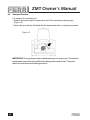
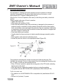
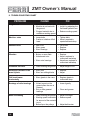
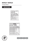
1
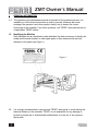
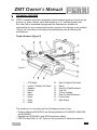
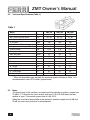
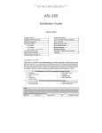
ZMT Owner’s Manual
Owner’s Manual
ZMT Offset / In-line
Verge Mowers
Maintenance & Use
ZMT Owner’s Manual
CONTENTS
GENERAL INFORMATION
• Introduction - Goal of the manual
• Identifying the machine
• Spare parts
section 1
section 1.1
section 1.2
section 1.3
page
page
page
page
2
2
2
2
TECHNICAL FEATURES
• General Description of the Shredder
• Technical Specifications
• Noise
• Width of Cut
• Optional Equipment
section 2
section 2.1
section 2.2
section 2.3
section 2.4
section 2.5
page
page
page
page
page
page
3
3
4
4
5
5
SAFETY RULES
• General Safety Rules
• Safety Rules Concerning the Hydraulic System
• Safety Rules Concerning Road Traffic
• Safety Rules During Use
• List of Guards Fitted to the Machine
• Description and Location of Safety Decals
section 3
section 3.1
section 3.2
section 3.3
section 3.4
section 3.5
section 3.6
page
page
page
page
page
page
page
6
6
6
7
7
6
7
INSTRUCTIONS FOR INSTALLATION, HANDLING AND PARKING
• Lifting and Unloading
• Unpacking
• Attachment to and Detachment from the Tractor
• Attaching the PTO Shaft
• Tractor stability
• Parking
section 4
section 4.1
section 4.2
section 4.3
section 4.4
section 4.5
section 4.6
page
page
page
page
page
page
page
8
8
7
8
9
6
7
ADJUSTMENT AND SETTING UP
• Regulating the Height of Cut
• Adjusting Belt Tension
section 5
section 5.1
section 5.2
page
page
page
11
11
11
USE AND OPERATING RULES
• Ram Control
• Starting
• Working Mode
• Stopping
• Transport Position
section 6
section 6.1
section 6.2
section 6.3
section 6.4
section 6.5
page
page
page
page
page
page
12
7
12
12
7
12
MACHINE MAINTENANCE
section 7
page
13
TROUBLE SHOOTING CHART
section 8
page
14
REPLACING PARTS
• Flails Replacement
• Pipe Replacement
• Pin Replacement
• Belt Replacement
section 9
section 9.1
section 9.2
section 9.3
section 9.4
page
page
page
page
page
15
15
11
15
11
DEMOLITION, DIFFERENTIATED DIVISION AND DISPOSAL
section 10
page
14
1
ZMT Owner’s Manual
1
GENERAL INFORMATION
1 .1 This operation and maintenance manual is intended for the professional user. It is
mandatory to follow these instructions in order to prevent situations that could
endanger the operator’s and other people’s safety, and to ensure the correct
functioning of the shredder. If you have questions, call “FERRI” after-sales service or
a specialized “FERRI” dealer.
1.2
Identifying the Machine
Each shredder has an identification plate attached; the data necessary to identify the
model and the serial number to order spare parts or after-sales service are both
stamped on the plate (see Figure 1)
Figure 1
1.3
2
It is strongly recommended to use genuine “FERRI” spare parts to avoid altering the
technical features of the shredder. “FERRI” is not responsible for any damage or
injuries to people due to unauthorized modifications or to the use of non-genuine
spare parts.
ZMT Owner’s Manual
2
TECHNICAL FEATURES
2.1
FERRI shredders have been designed to shred materials growing or laying on the
ground, e.g. grass, bushes, sticks and shrubs up to .8”. diameter (proper use).
Any other use is considered improper and the manufacturer disclaims all
responsibility for any consequential injuries to people or for damage to the machine.
“Proper use” also refers to the safety and maintenance rules provided by the
manufacturer.
Technical Names (Figure 2)
Figure 2
1
2
3
4
5
6
7
8
9
-
PTO Shaft
Levers To Adjust Flail Head
Gearbox
Pulleys
Belts
Frame
Rotor
Flails
Roller
10
11
12
13
14
15
16
17
-
Ram To Adjust Flail Head
Stand
Arms For Side Movement
Joint Pin
3-Point Linkage
Ram For Side Movement
Front Guard
Side Guard
This machine is in conformity with the following provisions of law:
• Directive Machine 89/392/CEE and following additions: 91/368/CEE, 93/44/CEE
and 93/68/CEE;
• Regulations UNI EN 292/1 and 292/2 (machinery safety);
• DPR 27th April’1955, N. 547 (Rules for the prevention of industrial accidents).
3
ZMT Owner’s Manual
2.2
Technical Specifications (Table 1)
Table 1
Model
ZMT 160
ZMT 180
ZM T200
Width of cut
ft.
63”
71”
79”
Min. Tractor required power
HP
50 - 60
60 - 70
70 - 80
4818
5256
5694
Min. Tractor Weight
PTO speed
rpm
540
540
540
Max. Absorbed Power*
HP
32
52
52
Weight Machine / Weight PTO Shaft
lbs.
984 / 53
1178 / 53
1237 / 53
3-point linkage
cat.
II - III
II - III
II - III
Rotor Speed
rpm
2430
2510
2510
Multi-Use Flails
num.
40
48
48
Hammer Flails
num.
20
24
24
Max. Pressure
psi
2750
2750
2750
A - Width
in.
63”
71”
79”
B - Length
in.
35”
37”
37”
C - Height
in.
17”
19”
19”
D - Total Height
in.
26”
28”
28”
E - Total Width
in.
70”
77”
85”
Dimensions
* When the absorbed power exceeds the maximum power indicated in Table 1 it is
recommended to use a PTO clutch (torque limiter).
2.3
4
Noise
The sound level of this machine, as measured at the operator’s position, ranges from
75 dB to 77.2 dB when the cab is closed, and from 81.9 to 83.4 dB when the rear
window is open. The acoustic power level is LWA 102.5.
When the sound level perceivable at the operator’s position ranges from 85 dB and
90 dB, the use of ear protectors is recommended.
ZMT Owner’s Manual
2.4
Width of Cut Figure 3 shows the width of cut of the shredder.
Dimensions are shown in Table 2.
Figure 3
Table 2
2.5
Model
ZMT 160
ZMT 180
ZMT 200
A
63”
71”
79”
C
88”
96”
104”
G
73”
76”
76”
H
25”
25”
25”
I
69”
72”
72”
L
63”
63”
63”
Optional Equipment
2.5.1 Flails
Depending on the different crops to be cut, suitable flails can
be fitted and used:
• Articulated flails for grass, shrubs, sticks and bushes of up
to 1.2” in diameter.
• Forged hammer blades for grass, twigs, shrubs, bushed up
to 1.2” in diameter.
5
ZMT Owner’s Manual
3
GENERAL SAFETY RULES
3.1
General Safety Rules:
• It is mandatory to read and follow the instructions from the use and maintenance manual
before carrying out any operation or moving the shredder. Improper use or moving it
improperly may seriously damage property and harm people.
• Both the operator and maintenance fitter must know the shredder well, especially
regarding dangers resulting from improper use or incorrect repairs.
• Before starting, check the tractor and shredder in regards to functionality, road safety
and accident prevention rules.
• Even when using the shredder correctly, stones or other objects may be thrown a long
distance. Therefore, nobody should be standing within the danger area. Special
attention must be paid when working near roads or buildings.
• Use tractor with cabs.
• The condition of flails and of all guards must be checked before beginning the daily
work. They must be replaced if damaged or missing.
• During checks or repairs, make sure nobody can start the shredder by mistake.
• Never wear loose or fluttering clothes.
• Never carry passengers on the tractor.
• Never carry passengers on the shredder.
• Never enguage the PTO with the engine stopped.
• Never approach the shredder until the rotor has completely stopped.
• Do not enter the working zone of the PTO shaft while it is in motion. It is dangerous to
approach the rotating parts of the machine.
• Keep the PTO shaft guard in good working order.
• Before starting, check the surrounding area for the eventual presence of children and or
animals.
• DO NOT stand in the range of operation of the machine.
• The PTO shaft must be assembled and disassembled only with the engine is stopped
and the ignition key removed.
• Before connecting the power take-off, check that the speed and rotation direction
corresponds to those of the shredder.
• Before leaving the tractor with the shredder attached, proceed as follows:
1.
2.
3.
4.
Disconnect the power takeoff.
Put the machine firmly on the ground (with the hydraulic lift).
Apply the hand brake and if the ground is sloping steeply, wedge the tractor
wheels.
Take the ignition key out.
• Immediately replace any safety sign or missing, damaged decal.
6
ZMT Owner’s Manual
3.2
Safety Rules Concerning the Hydraulic System
• This shredder uses the hydraulic circuit of the tractor to carry out side movements
and to adjust the flail head; the pressure of such system must not exceed 190 BAR.
• Mark the different pipes to avoid reversal of operation.
IMPORTANT: Do not look for oil leaks with bare hands, but always while wearing
gloves or with a cloth. Oil under strong pressure may seep into the skin causing
serious infections. In this case contact a doctor immediately.
• Periodically check the flexible hoses; if they are worn or damaged they must be
replaced with others of the same specification.
• Before working on the hyudraulic system, lower the machine, take pressure out
and stop the tractor.
• Used oils and greases must be stored and disposed of according to anitpollution
rules.
3.3
Safety Rules Concerning Road Traffic
• In transport, reduce speed, especially on bumpy roads. The weight of the shredder
may render driving difficult and damage the shredder itself.
• Check that the levers which operate the hydraulic lift are locked to avoid the
lowering of the machine during transport.
• When driving on public roads, respect all road rules in force. Never transport the
shredder with the rotor moving, even for short distances.
• Lock the shredder with the appropriate chain.
3.4
Safety Rules During Use
• Pay special attention, when working with the machine, not to touch fixed objects
such as road drains, wells, shafts, curbs, guard rails, tracks, etc. This could cause
the breakage of the flails, which can be thrown at very high speed.
• If wires, ropes or chains should get entangled in the rotor, stop immediately to
prevent damage or a dangerous situation; stop the rotor and the tractor, take out
the ignition key.
Put working gloves on, clear the rotor with the aid of pliers or shears. Do not try to
disentangle by inverting the rotational direction of the rotor.
• Do not use the machine when there is vibration in the flail head, as this could
cause breakage and serious damage. Find the cause of the vibration and repair it.
• Do not operate with the arm extended if the tractor is on a sloping ground.
3.5
List of Guards Attached to The Shredder (Figure 4)
1 - PTO Shaft
2 - PTO Shaft Guard
3 - Belt Guard
4 - Danger and Warning Decals
5 - Front Guard
6 - Side Guard
Figure 4
7
ZMT Owner’s Manual
3.6
Description and Location of Safely Decals (Figure 5)
Carefully follow the instructions detailed on the decals.
Figure 5
Description of the Decals
1. Warning of danger through lack of knowledge of all the functions of the machine
and the resulting risks: read the use and maintenance manual before operating
the shredder.
2. Danger sign of crushing or shearing: do not put limbs in the moving parts of the
machine where this decal is located.
3. Danger sign: it shows the risk of flying stones or other objects and it is mandatory
to keep out of the danger zone.
4. Danger sign of rotating flails: do not enter the area of operation with hands or feet.
5. Danger of getting entangled: do not approach the rotating PTO shaft. Pay special
attention to clothes which must not be loose or fluttering.
6. Danger of crushing: keep out of the danger zone. Before you make any
adjustments or perform maintenance it is neccesary to lock the hydraulic cylinders.
8
ZMT Owner’s Manual
4.
4.1
INSTRUCTIONS FOR INSTALLATION AND
HANDLING
Figure 6
Lifting and Unloading
To handle the shredder use a hoist or a crane
with lifting capability suitable to the weight of
the machine (see Table 1) and with proper
chains and type approved hooks attach them
to the marked points, as shown in Figure 6.
4.2
Packing
To make transport easier, the shredder can be supplied in a special pack
(disassembled and on pallets).
In this case, a card showing the reassembling procedure will be attached to the Use
and Maintenance Manual.
4.2.1 Instructions For Assembly
Instructions for the assembly of the mower when it is shipped partially dismounted
(Figure A).
Figure A
In order to have the mower stable during the operations, hook the mower up to the shift
of the tractor.
• Switch off the tractor.
• Cut the fixing strings used for transport reasons.
• Bring the arm (1) and put it on the ground.
• Turn the arm (2) around as shown on Figure B.
• Put the arm (1) on the proper support (3) & (4) and lock with threaded pins (5).
• Fix the cylinder (6) (rod side) with threaded pin (7).
9
ZMT Owner’s Manual
Figure B
WARNING: All Operations Must Be Done Without The PTO Sharft Mounted.
4.3
Attachment to and Detachment from the Tractor
Before carrying out this operation and whenever the shredder is used, it is important
to:
• Visually check the machine in general.
• Check that all guards are fitted and in good condition.
• Confirm that all flails are fitted and in good condition.
• Grease the bearings and any other part as indicated by a decal (Figure 21).
• Check that all hydraulic pipes are in good condition, look for signs of leakage
beneath the machine.
• Check that the number or revolutions and the rotational direction of the power take
off correspond to those required by the shredder (Figure 7).
Figure 7
10
ZMT Owner’s Manual
• To attach the machine to the tractor (Figure 8), bring the tractor lower lines (1) near the
shredder, to the points corresponding to the pins.
• Insert the pins (2) and secure them with the spring clips (3).
• Fit the top link (4) and adjust it at the limit of the slot side tractor (see Figure 8) in
order to follow any small depression on the ground. Raise the shredder to a
perpendicular position with the ground. Adjust the two tractor lower linkage
stabilizers (3) thus fixing the machine to the tractor in a central position.
• Lift the stand (5).
• Connect the pipes for ram control to the tractor and mark them to avoid reversing
them during assembly (see Figure 15).
Figure 8
• Proceed in reverse order to detach the shredder from the tractor.
Figure 9
4.4
Fitting The PTO Shaft
4.4.1 Following the instructions in 4.3,
assemble the PTO shaft (6) and check
that the overlap is not less than 2/3 of L.
Be sure to keep a 1.6” backlash (Figure
8). If it needs shortening, proceed as in
(Figure 9).
4.4.2 The guards of the PTO shaft must be
fixed to the shredder and to the tractor
with chains to prevent rotation. The
minimum overlap of the guard and the
PTO shaft must not be less than 2”
(Figure 10).
Figure 10
11
ZMT Owner’s Manual
4.5
Tractor Stability
Due to the design of the shredders and the work they do, it is essential to ensure
tractor stability in order to eliminate any risk of an imbalance or overturning.
Lift the shredder and check that the tractor’s front tires do not lift up. In case they do,
ballast the rear wheel of the tractor opposite to the extended arms and in front.
(Figure 11).
Figure 11
IMPORTANT:
• Never work with the extended arms when the tractor is on sloping grounds.
• During transport, the machine must be in the central position.
4.6
Parking
• Park the machine in a safe place, on flat and firm ground, in order to prevent the
risk of rolling over.
• Lower the shredder to the ground with the aid of the hydraulic lift of the tractor.
After lowering and blocking the stand, close the arms and lower the flail head to the
ground (Figure 12).
Figure 12
12
ZMT Owner’s Manual
5
ADJUSTMENT AND SETTING UP
5.1
Adjustment of the height of cut is obtained by shifting the flail head roller in order to
suit the material to be cut and the required degree of chopping (Figure 13).
Figure 13
IMPORTANT: Flails must never touch the ground.
5.2
Adjusting belt tension
This operation must be carried out with the shredder standing on the ground, the
power takeoff disconnected and the iginition key removed.
Remove the belts guard, loosen the 4 screws (1) fixing the gearbox, adjust the link
(2) to obtain a belt deflection of no more than .6”. with 10 lbs. of pressure applied
(see Figure 14).
Figure 14
At the end of the operation, tighten the 4 screws (1) holding the gearbox and reassemble
the belts guard.
13
ZMT Owner’s Manual
6
USE AND OPERATING RULES
6.1
Ram control
6.1.1 The ram control levers of the shredder are placed inside the cab and are part of the
shredder. This delivers the hydraulic power necessary to run the shredder.
• Ram (1) (Figure 15) controls the adjustment of the flail head.
• Ram (2) controls side movement of the flail head.
Figure 15
6.1.2 Controls with distributor (OPTIONAL)
For tractors equipped with just one pressure tube or when requested by the user, a
distributor for ram control can be fitted to the shredder. This is also equipped with a
floating position to control the ram (1) (Figure 15).
6.2
•
•
14
Starting
Before using the shredder check the tightness of all bolts and the integrity of all
guards. Check that the number of revolutions and the rotational direction of the
power takeoff of the tractor correspond to those required by the shredder, see
decal on the gearbox (Figure 7).
Engage the power takeoff at low engine RPM (without jerking) to avoid damaging
the transmission (gearbox and belts).
ZMT Owner’s Manual
6.3
Working Mode
6.3.1 Adjust the machine to suit the type of work to be done and the material to be cut:
• Adjust the height of cut, as shown in Figure 13.
Working speed is chosen to suite the material to be cut and the degree of chopping
required.
The optimum speed ranges from 2 to 5 miles per hour.
IMPORTANT: When extending and closing the arms, lightly lift the flail head off the
ground, to avoid damage to the frame (Figure 16)
Figure 16
IMPORTANT: During reverse movement, lift the shredder off the ground to avoid
damaging the machine (Figure 17 & 18)
Figure 18
Figure 17
6.4
Stopping
Before stopping the tractor:
• Close the arms and lower the flail head to the ground.
• Disconnect the power takeoff.
• Stop the tractor, take out the ignition key and apply the hand brake.
• If the ground is sloping, block the tractor wheels.
15
ZMT Owner’s Manual
6.5
Transport Position
For transport it is mandatory to:
• Observe all road transport requirements and fit the necessary warning signs
(Figure 19).
• Secure the arm and the flail head with the appropriate chain, to prevent movement.
Figure 19
IMPORTANT: During transport reduce speed especially on bumpy roads. The weight of
the shredder may render driving difficult and damage the machine itself. The power
takeoff must be disconnected during transport.
16
ZMT Owner’s Manual
7
MACHINE MAINTENANCE
All maintenance, cleaning and repair operations must be carried out with the
shredder firmly lowered to the ground and detached from the tractor, or with
disconnected PTO, engine off and ignition key out.
After the first 2 hours of operation from new (or after fitting new belts), check belt
tension.
Check regularly after every 8 hours’ operation:
• Tighten bolts and nuts.
• Check wear and condition of flails.
• Check that the protection flaps may be blocked or damaged by the presence of
mud and stones or residuals of mown material. Should this be the case stop the
tractor immediately, clean and repair the protection flaps as necessary. Adjustmets
or maintenance work should only be carried out when the machine is stopped and
the tractor engine is switched off.
• Check belt stretch and condition.
• Visually check the frame and arms to detect possible damage caused by earlier
work.
• Check gearbox and extension lubricating levels.
• Grease the parts as shown on the appropriate decal (Figure 20).
Figure 20
This operation must always be carried out at the end of each working day. This
facilitates the removal of mud or other material from the rotating parts (bearing, pins,
etc.) in order to avoid rust and possible seizure.
• Every 100 hours’ operation, grease the moving parts of the PTO shaft, extracting
the two parts of the shaft.
• After long inactivity, repeat the operation before re-using the machine.
• Use grease such as AGIP GR MU EP/2 (classification DIN 51825 (KP 2 K).
To fill oil to level, use:
• For gearbox use oil AGIP BLASIA 220 or compatible oils (classification ISO VG
220).
• Amount of oil (at level) ,5 quarts.
17
ZMT Owner’s Manual
8. TROUBLE SHOOTING CHART
PROBLEM
CAUSE
FIX
Irregular cut
• Worn, bent or broken fails
• Machine is not level with
the ground
• Clogged material due to
excessive working speed
• Replace
• Level it by adjusting the
flail head hydraulic ram
• Reduce working speed
Machine noise
• Loose bolts
• Cracks or initiation of flail
head
• Tighten bolts
• Have it repaired in
specialized workshop
Gearbox noise
• Lack of oil
• Worn gears
• Worn bearings
• Fill to level
• Replace
• Replace
Vibration
• Broken or worn flails
• Unbalanced rotor
• Replace
• Have it replaced in
authorized workshop
• Have them replaced in
authorized workshop
• Worn rotor bearings
Premature flail wear
• Flails touching the ground
• Adjust height of cut
Excessive backlash in the
arms & joints
• Worn pins
• Worn arm sliding blocks
• Replace
• Adjust
Flail head lowers
involuntarily
• Worn glands in the rams
• Replace glands in
authorized shop
Breakage of roller bearings
• Violent impact on the
ground when the arm is
lowered
• Dirty or little greased
bearings
• Lower it gently
• Flails touching the ground
• Working speed unsuitable
for amount of the material
to cut
• Belts slip on the pulleys
• Adjust cut height
• Reduce speed
Belts overheating
18
• Clean and grease
• Adjust belt tension
17
ZMT Owner’s Manual
9
REPLACING PARTS
Before carrying out any work, it is mandatory to:
• Lower the shredder to the ground.
• Disconnect the power takeoff, stop the tractor and take out the ignition key.
• Wear working gloves.
Figure 21
9.1
Flail Replacement
When the flails are worn, they must all be
replaced. In case of a partially broken flail it is
advisable to replace the broken one and the
one diametrically opposite, in order to maintain
the balance (Figure 21).
9.2
Pipe Replacement
• Before working on the hydraulic system, bleed all pressure, working with the
engine stopped and using all control levers.
• Pay particular attention to cleanliness as dirt and dust can cause considerable
damage to the hydraulic system
• Replace any damaged pipes with genuine spare parts or with others of the same
specification; ensure that they are not kinked or twisted, remembering to check this
throughout the entire cycle of arm movement.
9.3
Pin Replacement
• Carry out this operation with the aid of a lift or hoist, to prevent detached
component from falling, and also to avoid upsetting the balance of the machine.
• When replacing parts, clean and grease their housings.
9.4
Belt Replacement
This operation must be carried out with the flail head touching the ground, the power
takeoff disconnected and the ignition key out.
• Remove the beltguard, loosen the screws (1) (Figure 14), unscrew the tightener
(2), remove the belts and replace them with similar ones for dimensions and type.
See 5.2 for registration.
IMPORTANT - More complex operations must be done in authorized workshops.
19
ZMT Owner’s Manual
10
DEMOLITION, DIFFERENTIATED DIVISION OF THE MATERIALS AND DISPOSAL
If the machine is in need of disposal, all its parts that might be dangerous to the
enviroment have to be made safe. The materials on the machine that have to
undergo a differentiated division are:
• steel
• mineral oil
• rubber
• plastic
• electric system conductors
All the above modification operations and the final disposal have to be carried out in
total respect of the present provisions of law on the subject.
20