1
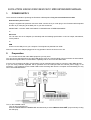
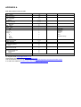
Evolution USB Keyboards
249/361
USB MIDI Controller Keyboard
225C/249C/361C
USB MIDI Controller Keyboard with additional
programmable rotary controllers
WWW.EVOLUTION.CO.UK
EVOLUTION 249/361/225C/249C/361C MIDI KEYBOARD MANUAL
1.
POWER SUPPLY
There are three methods of powering the Evolution USB Keyboard. Only use one method at one time
Soundcard as power source
Using the supplied self powered connector cable connect the 5 pin male plug to the Evolution MIDI keyboard
and the 15 pin male plug to the MIDI port on your PC soundcard.
IMPORTANT – DO NOT USE THIS CABLE TO POWER ANY OTHER EQUIPMENT
or
AC Power
You can also use an AC adapter (not included) with the following specification: 9-12V DC output, 250-300mA,
centre positive.
or
USB
Connect to the USB port on your computer. The keyboard is powered from USB.
Note: Do not leave the adapter plugged in for long periods of time if the unit is not in use.
2.
Preparation
2-1 Connect the unit with other MIDI equipment you may have:
You can connect the keyboard to any other MIDI device such as a sound module or drum machine as shown below.
Note that the keyboard does not have MIDI in capability and so can not receive MIDI data.
If you are not connecting via USB, you will need to use an external power supply to connect to other MIDI devices.
If you are using USB the keyboard will be powered from the USB port and the external power supply is not
necessary. The keyboard can act in MIDI THRU mode receiving data from the computer and transmitting it to any
other connected MIDI device.
Turn on the POWER switch.
Turn all other equipment on.
Press the BANK MSB and TRANSPOSE simultaneously to select ‘MIDI out from USB’ (only necessary if using
the USB port).
3.
Demo
Pressing octave up and down together plays a short demonstration. Please note that the sounds are set for a GM
sound system and the demo will sound differently on other sound synthesizers.
Press the octave up and down keys once more to end demo.
4.
Entering Numbers
When any number is entered it adheres to the following rules:Increment/Decrement Keys
Initially the LED display starts flashing.
The value displayed can be incremented/decremented using the +/- keys.
Pressing both + & - should call up the default value for that parameter.
The LED display shows the new value.
The new value is sent out except for the CONTROL ASSIGN which sends data when the display stops flashing)
When the display stops flashing the keyboard returns to normal operation.
Numeric Keys
Initially the LED display starts flashing.
A numeric value can be typed in using the numbers 0-9.
As each key is pressed the display continues to flash, the time-out value is reset.
When a complete number* has been entered the display stops flashing and the value is selected.
Alternatively, if no key is pressed and the display stops flashing the number on the display is selected.
The update routine is triggered, so that the new value is sent out.
When the display stops flashing the keyboard returns to normal operation.
* The following table shows how many keys are required to enter a complete number:-
Channel
Memory
Program Changes
Bank LSB/MSB
Control Select
Control Assign
5.
1 key
2-9
0-9
2-9
2 keys
01,10-16
3 keys
13-99
13-99
01,10-14
14-99
000-012, 100-127
000-012, 100-127
000-013, 100-132
Sending a PROGRAM CHANGE number
Using the PROGRAM switch and the numeric keys, you can send any MIDI PROGRAM CHANGE from 0-127.
Press the PROGRAM switch. The LED starts to flash showing the current PROGRAM number (instrument
sound).
Press the numeric keys to alter the PROGRAM CHANGE number. You can also use the “+” or “-” keys to
change the value.
Note: * if you don’t do anything for 3 seconds the LED stops flashing and shows the current PROGRAM CHANGE
number.
À if the number you press is larger than 127, it will return to the previous PROGRAM CHANGE number.
6.
PROGRAM & BANK CHANGE MEMORY
You can assign a selected PROGRAM CHANGE as well as a BANK LSB and a BANK MSB to one of ten numeric
keys (0-9). Once stored, simply pressing one of the numeric keys will send the desired PROGRAM and BANK
CHANGES. The stored information is held in non-volatile memory which will remember even if the power is turned
off.
Select the desired PROGRAM CHANGE, BANK LSB and MSB. Please refer to respective chapters for information
on how to do this.
Press the MEMORY switch. The LED starts to flash.
Press the numeric key (from 0 to 9) you wish to assign the data to. The PROGRAM and BANK CHANGE
information is stored on the selected numeric key.
7.
Setting the MIDI Transmit Channel
There are 16 MIDI transmit channels available. Once you have set the unit’s MIDI channel, the unit sends all MIDI
messages on this MIDI channel. Be sure to match the channel with the RECEIVE channel of any connected
equipment.
Press the CHANNEL switch. The LED shows the present TRANSMIT channel
Press one (or two) of the numeric keys to change the channel. The LED changes to the pressed number.
You can also use +/- switches to increase or decrease the value.
Note: * if you do nothing after step 3-1 for 3 seconds, the LED will return to show the present PROGRAM
CHANGE number.
The default CHANNEL is 1 when power is turned on.
If you have a MK-225C/MK-249C/MK-361C, you can assign each of the rotary controls to a different channel
individually. You can store a single channel for each of the controllers that is independent of the Keyboard channel.
This allows you to transmit control data on multiple channels simultaneously. To do this:
1. Press both 'CONTROL SELECT' buttons and release.
2. The LED display shows the current controller which has been selected.
3. As the LED toggles the display between the new controller and its assignment, presss the CHANNEL
button. A small ‘c’ in the first digit indicates that it is displaying the channel for the selected controller, the
other 2 digits display the current controller channel.
4. Press one (or two) of the numeric keys to change the channel. The LED changes to the pressed
number.
5. You can also use +/- switches to increase or decrease the value.
Note:
You can select a new controller by moving any one of the rotary controllers.
If you have one of the new blue LED keyboards you can alternatively use the 'CONTROL ASSIGN' buttons.
When a Controller is assigned a channel of 0 it means that rather than have a single, assigned channel it reads the
current Keyboard channel instead and generates MIDI data on the same channel as notes played on the keyboard.
8.
SLIDER ASSIGN
Moving the SLIDER transmits MIDI CONTROL CHANGE messages to any connected equipment. The Slider
defaults to sending Channel Volume messages on the selected channel, but you can re-assign the slider to any
other controller.
Number
1 – 127
128
129
130
131
132
Functions
Standard MIDI controllers
Pitch Bend Sensitivity
Fine Tune
Coarse Tune
Channel Pressure
Velocity
With Evolution 249/361. Press the SLIDER ASSIGN switches (PROGRAM & BANK LSB) together and the LED
starts to flash showing the number of the present MIDI controller.
Use numeric keys 0-9 to select a new MIDI controller. You can also use the +/- switches to increase or
decrease the value of the number.
With Evolution 225C/249C/361C. Press the CONTROL SELECT switches (MEMORY & PROGRAM) and the
LED starts to flash showing the number of the present MIDI controller.
Move the slider. Alternatively, press numeric keys 0-9 to select a new MIDI controller. You can also use the +/switches to increase or decrease the value of the number. The LED display should flash C13.
Note:
* If you do nothing for 3 seconds, the LED will return to show the current PROGRAM CHANGE number.
* If the number you press is not in the range of defined numbers, the previous number will be retained.
* When you assign 120 or 121 as the MIDI controller for the WHEEL, you should move the MODULATION
Wheel to the mid-value then return it to the minimum value to send a relative MIDI message.
See Appendix B for a full list of controller numbers.
9.
PITCH BEND WHEEL
Moving the PITCH BEND WHEEL transmits MIDI PITCH BEND messages to any connected equipment. This
allows you to bend the pitch of a sound up (or down one tone) to add expression to your performance.
To bend the sound up: Move the WHEEL away from you.
To bend the sound down: Move the WHEEL towards you.
10.
WHEEL ASSIGN
Use the WHEEL to transmit MIDI CONTROL CHANGE messages. You can select and assign 119 types of MIDI
functions (1-31, 33-95, 102-121, 128-132)
Number
1 –127
128
129
130
131
132
Functions
Standard MIDI controllers
Pitch Bend Sensitivity
Fine Tune
Coarse Tune
Channel Pressure
Velocity
With Evolution 249/361. Press the WHEEL ASSIGN switches (MEMORY & PROGRAM) together and the LED
starts to flash showing the number of the present MIDI controller.
Use numeric keys 0-9 to select a new MIDI controller. You can also use the +/- switches to increase or decrease the
value of the number.
With Evolution 225C/249C/361C. Press the CONTROL SELECT switches (MEMORY & PROGRAM) and the LED
starts to flash showing the number of the present MIDI controller.
Either move the wheel, or press numeric keys 0-9 to select a new MIDI controller. You can also use the +/- switches
to increase or decrease the value of the number. The LED display should flash C14.
Note:
* If you do nothing for 3 seconds, the LED will return to show the current PROGRAM CHANGE number.
* If the number you press is not in the range of defined numbers, the previous number will be retained.
* When you assign 120 or 121 as the MIDI controller for the WHEEL, you should move the MODULATION
Wheel to the mid-value then return it to the minimum value to send a relative MIDI message.
* See Appendix B for a full list of controller numbers.
11.
TRANSPOSE
This function allows you to shift the pitch of the unit in semitones. You can transpose the pitch by 24 half steps (12
up, 12 down).
Press the TRANSPOSE switch. The LED shows the current TRANSPOSE value.
Press the “+” or “-” switch to change the TRANSPOSE value. Each time you press + or -, the keyboard is
transposed an additional half step.
* Pressing the + and - switches simultaneously resets the pitch to the default value.
Note: Turning the power off always resets the shifted pitch to the default value.
12.
OCTAVE CHANGE
This function allows you to shift the pitch up to three octaves higher or two lower.
Press the OCTAVE UP or DOWN to change the octave range. The LED shows the new OCTAVE value.
* Press OCTAVE UP and DOWN switches simultaneously to reset the pitch to the default value.
Note: if the UP or DOWN switch is not pressed for 3 seconds, the LED will return to show the PROGRAM CHANGE
number.
13.
Sending BANK MSB and LSB message
You can send any value of MSB or LSB from 0-127.
Press the BANK LSB switch. The LED starts to flash showing the current value of the LSB. Press the numeric keys
to change the LSB value. You can also use the “+” or “-” switches to change the value.
Press the BANK MSB switch. The LED starts to flash showing the current value of the MSB. Press numeric keys to
change the MSB value. You can also use the “+” or “-” switches to change the value.
Note: * if you don’t do anything for 3 seconds the LED stops flashing and shows the current PROGRAM CHANGE
number.
* if the number you input is over 127, it will return to the previous LSB or MSB value.
14.
Selecting a VELOCITY CURVE
The VELOCITY CURVEs determine the relationship between how hard the keys are struck and the corresponding
velocity that the unit transmits.
This unit allows you to select from 12 VELOCITY CURVEs.
Simultaneously press the CHANNEL and MEMORY switches. The LED starts to flash showing the current number
of the VELOCITY CURVE.
Press one of the numeric keys to select a VELOCITY CURVE. The 10 key numbers correspond to the first 10
VELOCITY CURVEs as follows:
You can also use the “+” or “-” switches to access all the VELOCITY CURVEs.
There are 3 Fixed VELOCITY CURVEs which output the following velocity values:
Curve
Velocity
64
F0
100
F1
127
F2
These are achieved by selecting velocity curve 09. F0 will appear on the LED. Use the “+” or “-“ keys to select F0F2.
Note: If you don’t do anything for 3 seconds the LED stops flashing and shows the current PROGRAM CHANGE
number.
15.
MIDI OUT FROM USB
The MIDI output connector is normally used to send MIDI data from the keyboard. If the keyboard is connected to a
computer using USB the MIDI Out can also be used to send data received from USB.
Pressing both ‘MIDI OUT FROM USB’ buttons flashes the current setting on the LCD display.
The +/- keys can be used to alter the current setting. + selects YES, - selects NO.
Pressing both + and – calls up the default setting which is NO.
When ‘NO’ is selected the MIDI Out sends the data from the keyboard.
When YES is selected the MIDI Out sends the MIDI data received from USB.
The status of MIDI OUT FROM USB will be saved in non-volatile memory and restored when the keyboard is
switched on again. The factory default is set to NO
16.
GM RESET (GENERAL MIDI RESET) – Evolution 249/361 Only
This function allows you to send a GENERAL MIDI MODE RESET message.
Press the BANK LSB and BANK MSB keys together.
Hold the keys down for at about 2 seconds and the reset message is sent.
Evolution 225C/249C/361C Only
17.
Assignable Rotary controllers
All these assignable controllers are selected by the ‘CONTROL SELECT’ & 'CONTROL ASSIGN' functions for
these keyboards.
‘Assignable Controllers’ refers to any of the 8, 12 or 16 assignable Knobs and also includes the assignable Wheel
and Slider. The Slider is Assignable Controller 13 or 17(for MK249C and MK-361C only), the Wheel is Assignable
Controller 9, 14 or 18.
The basic operation is:Press the CONTROL SELECT buttons together. Select the controller by moving it or by typing the number in.
Press the CONTROL ASSIGN buttons and enter the new number using the keypad.
To change one of the assignable controllers, the keyboard uses the following method:
Press both 'CONTROL SELECT' buttons and release.
The LED display shows the current Controller which has been selected. The LED’s toggle between the
controller number and the assigned value. E.g. initially it would toggle between c14 & 01, showing that the
Wheel is assigned to the Modulation Wheel controller.
Select a controller by moving any one of the assignable controllers, the numeric keypad or the +/- keys.
The LED then toggles the display between the new controller and its assignment.
Repeat this process to see the controller number assignment (0-132) for any Knob, Slider or the Wheel, by
moving the relevant controller or by typing a new number.
If no keys are pressed or any of the assignable controllers moved, the LED display stops flashing after 3
seconds and returns to normal operation.
Press both 'CONTROL ASSIGN' buttons and release.
The number entered at this point will be assigned to the last selected controller.
The numeric entry uses the standard data entry system. (see section on Entering Numbers)
If a complete number is entered the display stops flashing and the new assignment is stored.
If the +/- keys are used, the revised value is shown on the LED display and the flashing time-out is reset.
Once a controller has been assigned the current knob/slider/wheel position should be sent out.
This ensures that when the controller if first moved it does not trigger a large jump from it’s previous setting.
During the data entry stage while the LED display is flashing, the Knobs, Slider and the Wheel do not function.
The MIDI keyboard should continue to function at all times
18.
Snap Shot
When both SNAP SHOT keys are pressed the MK-249C sends out the settings for all of the Assignable Controllers
on the current selected channel. This feature lets you record the settings of the Knobs, Slider & Mod Wheel into
your sequencer.
19. SPECIFICATIONS
Evolution 249:
1. Keyboard: 49 standard keys (Velocity sensitive)
2. Control: Switches: (WHEEL, CHANNEL, PROGRAM, MEMORY, TRANSPOSE, GM RESET, VEL CURVE,
BANK LSB, BANK MSB, OCTAVE DOWN, OCTAVE UP, POWER ON/OFF, Numeric Keys (0-9), , +)
3. Control: Sliders: (PITCH BEND WHEEL, MODULATION WHEEL, CHANNEL VOLUME/DATA ENTRY)
4. Memory storage – non volatile
5. Display: 3 digit LED
6. Jack: DC IN (DC 9V), MIDI OUT, SUSTAIN, USB
7. Dimension: 800 x210 x80 (mm). Weight: 4 kg
Note: Specifications are subject to change without prior notice.
Evolution 361:
1. Keyboard: 61 standard keys (Velocity sensitive)
2. Control: Switches: (WHEEL, CHANNEL, PROGRAM, MEMORY, TRANSPOSE, GM RESET, VEL CURVE,
BANK LSB, BANK MSB, OCTAVE DOWN, OCTAVE UP, POWER ON/OFF, Numeric Keys (0-9), , +)
3. Control: Sliders: (PITCH BEND WHEEL, MODULATION WHEEL, CHANNEL VOLUME/DATA ENTRY)
4. Memory storage – non volatile
5. Display: 3 digit LED
6. Jack: DC IN (DC 9V), MIDI OUT, SUSTAIN, USB
7. Dimension: 970 x220 x80 (mm). Weight: 5 kg
Note: Specifications are subject to change without prior notice
Evolution 225C:
1. Keyboard: 49 standard keys (Velocity sensitive)
2. Control: Switches: (WHEEL, CHANNEL, PROGRAM, MEMORY, TRANSPOSE, GM RESET, VEL CURVE,
BANK L, BANK M, RESET-AC, OCTAVE DOWN, OCTAVE UP, POWER ON/OFF, Numeric Keys (0-9), ?, +)
3. Control: Sliders: (PITCH BEND WHEEL, MODULATION WHEEL, CHANNEL VOLUME/DATA ENTRY)
4. Rotary Controls: 12 rotary controls with assignable controller values
5. Memory storage – non volatile
6. Display: 3 digit LED
7. Jack: DC IN (DC 9V), MIDI OUT, SUSTAIN, USB
8. Dimension: 480 x220 x80 (mm)
9. Weight: 2.3 kg
Note: Specifications are subject to change without prior notice.
Evolution 249C:
1. Keyboard: 49 standard keys (Velocity sensitive)
2. Control: Switches: (WHEEL, CHANNEL, PROGRAM, MEMORY, TRANSPOSE, GM RESET, VEL CURVE,
BANK L, BANK M, RESET-AC, OCTAVE DOWN, OCTAVE UP, POWER ON/OFF, Numeric Keys (0-9), ?, +)
3. Control: Sliders: (PITCH BEND WHEEL, MODULATION WHEEL, CHANNEL VOLUME/DATA ENTRY)
4. Rotary Controls: 12 rotary controls with assignable controller values
5. Memory storage – non volatile
6. Display: 3 digit LED
7. Jack: DC IN (DC 9V), MIDI OUT, SUSTAIN, USB
8. Dimension: 800 x210 x100 (mm)
9. Weight: 4 kg
Note: Specifications are subject to change without prior notice.
Evolution 361C:
1. Keyboard: 61 standard keys (Velocity sensitive)
2. Control: Switches: (WHEEL, CHANNEL, PROGRAM, MEMORY, TRANSPOSE, GM RESET, VEL CURVE,
BANK L, BANK M, RESET-AC, OCTAVE DOWN, OCTAVE UP, POWER ON/OFF, Numeric Keys (0-9), ?, +)
3. Control: Sliders: (PITCH BEND WHEEL, MODULATION WHEEL, CHANNEL VOLUME/DATA ENTRY)
4. Rotary Controls: 16 rotary controls with assignable controller values
5. Memory storage - non volatile
6. Display: 3 digit LED
7. Jack: DC IN (DC 9V), MIDI OUT, SUSTAIN, USB
8. Dimension: 970 x220 x100 (mm)
9. Weight: 5 kg
Note: Specifications are subject to change without prior notice.
APPENDIX A
MIDI IMPLEMENTATION CHART
Function
Basic :Default
Channel:Changed
:Default
Mode :Messages
:Altered
Note
Number:True Voice
Velocity: Note ON
: Note OFF
After :Key’s
Touch :Ch’s
Pitch Bend
0,32
1
Control 6
Change 7
64
1-31
33-95
102-121
Program
Change:True Number
System Exclusive
:Song Position
Common:Song Select
:Tune
System :Clock
Exclusive:Commands
Aux :Local ON/OFF
Messages:All Notes OFF
:Active Sense
:Reset
Notes:
Transmitted
1-16
1-16
--------X
*********
0-127
*********
0
X
X
•
0
•
•
•
0
0
Received
Bank select
Modulation
Data Entry
Volume
Hold 1
Mod Wheel Assign
•
•
•
0-127
*********
X
X
X
X
X
X
X
X
0
X
• : Can be
Remarks
set to 0
or X
For support email [email protected]
Latest drivers and information at www.evolution.co.uk
Join the Evolution User’s group at Yahoo groups, www.yahoogroups.com/group/evolution-users
or e-mail to this address: [email protected]
APPENDIX B
STANDARD CONTROLLER NUMBERS
No.
Controller
No.
Controller
No.
Controller
00
01
02
03
04
05
06
07
08
09
10
11
12
13
14
15
16
17
18
19
20
21
22
23
24
25
26
27
28
29
30
31
32
33
34
35
36
37
38
39
40
41
42
43
44
45
46
47
48
49
50
Bank Select
Modulation
Breath Control
Controller 3
Foot Control
Porta Time
Data Entry
Channel Volume
Balance
Controller 9
Pan
Expression
Effects Controller 1
Effects Controller 2
Controller 14
Controller 15
Gen Purpose 1
Gen Purpose 2
Gen Purpose 3
Gen Purpose 4
Controller 20
Controller 21
Controller 22
Controller 23
Controller 24
Controller 25
Controller 26
Controller 27
Controller 28
Controller 29
Controller 30
Controller 31
Bank Select LSB
Modulation LSB
Breath Control LSB
Controller 35
Foot Control LSB
Porta Time LSB
Data Entry LSB
Channel Volume LSB
Balance LSB
Controller 41
Pan LSB
Expression LSB
Controller 44
Controller 45
Controller 46
Controller 47
Gen Purpose 1 LSB
Gen Purpose 2 LSB
Gen Purpose 3 LSB
51
52
53
54
55
56
57
58
59
60
61
62
63
64
65
66
67
68
69
70
71
72
73
74
75
76
77
78
79
80
81
82
83
84
85
86
87
88
89
90
91
92
93
94
95
96
97
98
99
100
101
Gen Purpose 4 LSB
Controller 52
Controller 53
Controller 54
Controller 55
Controller 56
Controller 57
Controller 58
Controller 59
Controller 60
Controller 61
Controller 62
Controller 63
Sustain Pedal
Portamento
Sostenuto
Soft Pedal
Legato Pedal
Hold 2
Sound Variation
Resonance
Release Time
Attack Time
Cutoff Frequency
Controller 75
Controller 76
Controller 77
Controller 78
Controller 79
Gen Purpose 5
Gen Purpose 6
Gen Purpose 7
Gen Purpose 8
Portamento Control
Controller 85
Controller 86
Controller 87
Controller 88
Controller 89
Controller 90
Reverb Depth
Tremelo Depth
Chorus Depth
Celeste (De-tune)
Phaser Depth
Data Increment
Data Decrement
Non-Reg Param LSB
Non-Reg Param MSB
Reg Param LSB
Reg Param MSB
102
103
104
105
106
107
108
109
110
111
112
113
114
115
116
117
118
119
Controller 102
Controller 103
Controller 104
Controller 105
Controller 106
Controller 107
Controller 108
Controller 109
Controller 110
Controller 111
Controller 112
Controller 113
Controller 114
Controller 115
Controller 116
Controller 117
Controller 118
Controller 119
Channel Mode Messages
120
121
122
123
124
125
126
127
All Sound off
Reset all Controllers
Local Control
All Notes Off
Omni Off
Omni On
Mono On (Poly Off)
Poly On (Mono Off)
Extra Keyboard Messages Possible
128
129
130
131
132
Pitchbend sensitivity.
Fine Tune
Coarse Tune
Channel Pressure
Velocity