1
RECORDERS
ESCORT 3016B, 3008B, 3004B
USER S MANUAL
Edition January 2007
M3008B/03
We wish to thank you for acquiring a recorder by ESCORT and for trusting our company. The main
goal of our different teams (design office, production, commercial, after-sale service ) is to match
with accuracy your needs by designing or updating high technology products.
You will find with your recorder a CD-ROM including:
-
The user s manual of the ESCORT 3016B, ESCORT 3008B and ESCORT 3004B
appliance
the "ESCORT View" software that allows you to save and work with your recording files
under Windows .
We would like you to read carefully this user s manual for an optimum use of your recorder.
Copyright ESCORT, 2006. All rights reserved
Any copy of this document, totally or partially, is submitted to an autorisation by ESCORT.
GARANTY
Your instrument is guaranteed for one year in parts and work time against any default of manufacture
and/or contingencies in the functioning. This guaranty starts at the date of delivery and ends 365
calendar days later.
If the appliance is subject to a guaranty contract, this contract cancels and replaces the above
mentioned conditions of guaranty.
This guaranty does not include any fault of use and/or error of handling.
In case of use of the guaranty, the user must send back the concerned appliance to our factory:
ESCORT Instruments Corporation
3F,No 6, Alley 6, Lane 45, Pao-Hsin Road, Hsin Tien, 231 Taipei, Taiwan R.O.C.
TEL: 886-2-2913-1325
FAX: 886-2-2918-3929
http://www.escorttw.com
The accessory items furnished as standard with the appliance (cables, plugs ) and the optional
accessory items (bag, case ) are guaranteed for 3 months against any default of manufacture.
The factory options in the appliance are guaranteed for the same time as the appliance.
What to do in case of malfunction?
In case of malfunction or for any problem of use, please contact the technical assistance by ESCORT
Instruments Corporation.
A technician will take your mail in charge and will give you any necessary information to solve your
problem.
What to do in case of crash?
In case of crash of the appliance, please join our after-sales service.
CONTENTS
1.
IMPORTANT INFORMATION ..............................................................................................................................1.1
1.1.
1.2.
1.3.
1.4.
2.
CAUTIONS ................................................................................................................................................................1.1
SECURITY INSTRUCTIONS .........................................................................................................................................1.1
SYMBOLS AND DEFINITIONS .....................................................................................................................................1.2
CONFORMITY AND RESTRICTIONS OF THE APPLIANCE ..............................................................................................1.2
PRESENTATION ......................................................................................................................................................2.1
2.1. GENERAL ..............................................................................................................................................................2.1
2.2. DESCRIPTION.......................................................................................................................................................2.2
2.2.1. Rear side (or top side) ...................................................................................................................................2.2
2.2.2. Front side.......................................................................................................................................................2.3
2.3. THE LCD SCREEN................................................................................................................................................2.3
Description of the screen .............................................................................................................................................2.3
2.4. KEYS ......................................................................................................................................................................2.4
2.5. THUMB WHEEL ...................................................................................................................................................2.5
2.6. LOCKING THE KEYBOARD ...............................................................................................................................2.5
2.7. USE OF A MOUSE ................................................................................................................................................2.5
2.8. USE OF AN EXTERNAL KEYBOARD ...............................................................................................................2.5
2.9. UPDATING THE INTERNAL SOFTWARE ........................................................................................................2.6
2.10.
USE OF THE SUPPORT LEG OF 8440............................................................................................................2.6
3.
INITIALISATION AND PRECAUTIONS OF USE ..............................................................................................3.1
3.1. ESCORT 3008B LOADING THE RECORDING PAPER ....................................................................................3.1
3.1.1. Storage precautions of the records ................................................................................................................3.2
3.2. POWER SUPPLY ...................................................................................................................................................3.2
3.2.1. Fuse ...............................................................................................................................................................3.2
3.2.2. Power up of ESCORT 3008B.........................................................................................................................3.3
3.2.3. Power up of ESCORT 3016B and ESCORT 3004B.......................................................................................3.4
3.3. CONFIGURATION ON POWER-UP ....................................................................................................................3.4
3.4. CONNECTION TO THE MEASURE NETWORK ...............................................................................................3.5
3.4.1. Measure of voltage.........................................................................................................................................3.5
3.4.2. Measure of temperature with a thermocouple ...............................................................................................3.5
3.4.3. Measure of temperature with a PT100 ..........................................................................................................3.5
3.4.4. Measure of intensity.......................................................................................................................................3.6
3.4.5. Connection of the grounding .........................................................................................................................3.6
3.5. ROUTINE MAINTENANCE ..........................................................................................................................................3.7
3.6. CALIBRATION OF THE OFFSETS .................................................................................................................................3.7
3.7. FACTORY ADJUSTEMENT ..........................................................................................................................................3.8
4.
USE..............................................................................................................................................................................4.1
4.1. « MODE » KEY .........................................................................................................................................................4.1
4.2. « HELP » KEY ...........................................................................................................................................................4.2
4.3. « SET UP » KEY.........................................................................................................................................................4.3
4.4. « CHART » KEY ........................................................................................................................................................4.5
4.5. « CHANNELS SET UP» KEY .......................................................................................................................................4.6
4.5.1. Analogical channels.......................................................................................................................................4.6
4.5.2. Logic channels ...............................................................................................................................................4.8
4.6. « CHANNEL ON/OFF» KEY ........................................................................................................................................4.9
4.7. « DISPLAY » KEY ...................................................................................................................................................4.10
4.7.1. Display F(t) (oscilloscope mode).................................................................................................................4.10
4.7.2. Display XY ...................................................................................................................................................4.12
4.7.3. Digital display .............................................................................................................................................4.12
4.8. DIRECTION KEYS ....................................................................................................................................................4.12
4.9. « TRIGGER » KEY ...................................................................................................................................................4.13
4.10.
4.11.
4.12.
5.
« REPLAY » KEY ............................................................................................................................................... 4.14
« START/STOP » KEY ........................................................................................................................................ 4.15
PAPER-FEED KEY ............................................................................................................................................... 4.16
DIAGRAMS ............................................................................................................................................................... 5.1
5.1. POSITIONS OF THE CHANNELS .................................................................................................................................. 5.2
5.2. CHANGE DIAGRAMS ................................................................................................................................................. 5.3
6.
TRIGGERS ................................................................................................................................................................ 6.1
6.1. TRIGGERING WITH ANALOGICAL CHANNELS ............................................................................................................ 6.2
6.1.1. Single threshold ............................................................................................................................................. 6.2
6.1.2. Several thresholds ......................................................................................................................................... 6.3
6.1.3. Trigger according to thresholds .................................................................................................................... 6.4
6.1.4. Trigger according to the slope ...................................................................................................................... 6.5
6.2. TRIGGERING WITH LOGICAL CHANNELS ................................................................................................................... 6.6
7.
MATHEMATICAL CALCULATIONS .................................................................................................................. 7.1
7.1. DEFINITIONS ............................................................................................................................................................ 7.1
7.2. TYPES OF CALCULATIONS ........................................................................................................................................ 7.2
8.
DIRECT MODE ........................................................................................................................................................ 8.1
8.1.
8.2.
8.3.
8.4.
8.5.
9.
CONFIGURATION OF THE PLOTTING .......................................................................................................................... 8.1
TRIGGERING PLOTTING ............................................................................................................................................ 8.3
REARMAMENT OF THE PLOTTING ............................................................................................................................. 8.5
WRITING DATA ........................................................................................................................................................ 8.5
EXAMPLE OF PLOTTING PROGRAM ........................................................................................................................... 8.5
MEMORY MODE..................................................................................................................................................... 9.1
9.1.
9.2.
9.3.
9.4.
9.5.
9.6.
9.7.
10.
GO/NOGO MODE .................................................................................................................................................. 10.1
10.1.
10.2.
10.3.
11.
CONFIGURATION AND TRIGGERING OF THE ACQUISITION ......................................................................................... 9.1
SAMPLING PERIOD ................................................................................................................................................... 9.2
INTERNAL MEMORY, BLOCKS................................................................................................................................... 9.3
TRIGGERING POSITION ............................................................................................................................................. 9.3
DOUBLE TRIGGER MODE .......................................................................................................................................... 9.4
RECORDING ............................................................................................................................................................. 9.4
MEMORY OUTPUT .................................................................................................................................................... 9.7
CONFIGURATION AND TRIGGERING OF THE ACQUISITION .................................................................................. 10.1
CREATION OF THE FRAME ................................................................................................................................. 10.2
USE OF THE FRAME ........................................................................................................................................... 10.4
FILE MODE ............................................................................................................................................................ 11.1
11.1.
CONFIGURATION AND START OF THE ACQUISITION ........................................................................................... 11.1
11.2.
LIMITS............................................................................................................................................................... 11.2
11.2.1. Binary file .................................................................................................................................................... 11.2
11.2.2. Ascii file....................................................................................................................................................... 11.2
12.
FILE MANAGEMENT........................................................................................................................................... 12.1
12.1.
GENERAL .......................................................................................................................................................... 12.1
12.2.
MANAGEMENT OF THE CONFIGURATION FILES .................................................................................................. 12.2
12.2.1. Saving the configuration files ...................................................................................................................... 12.3
12.2.2. Loading the configuration files.................................................................................................................... 12.4
12.3.
MANAGEMENT OF THE ACQUISITION FILES ........................................................................................................ 12.4
12.3.1. Saving the acquisitions ................................................................................................................................ 12.4
12.3.2. Loading the acquisition files........................................................................................................................ 12.6
12.4.
PC SOFTWARE FOR ANALYSIS ................................................................................................................. 12.6
12.4.1. File transfer with FTP ................................................................................................................................. 12.7
12.4.2. Display with ESCORT_VIEW ..................................................................................................................... 12.8
13.
PRINTING WITH ESCORT 3016B AND ESCORT 3004B................................................................................ 13.1
13.1.
PLOT SET UP AND LAUNCH ................................................................................................................................ 13.1
13.2.
14.
PRINTER SETUP .................................................................................................................................................13.3
INPUTS / OUTPUTS ...............................................................................................................................................14.1
14.1.
SUPPLEMENTARY INPUT / OUTPUT CONNECTOR .................................................................................................14.1
14.2.
LOGICAL INPUTS................................................................................................................................................14.2
14.2.1. Use ...............................................................................................................................................................14.2
14.3.
ALARM OUTPUTS ...............................................................................................................................................14.3
14.3.1. Use ...............................................................................................................................................................14.3
14.4.
POWER SUPPLY OUTPUT ....................................................................................................................................14.3
14.5.
KEYBOARD INPUT..............................................................................................................................................14.3
14.6.
MOUSE INPUT ....................................................................................................................................................14.4
14.7.
XGA SCREEN OUTPUT .......................................................................................................................................14.4
14.8.
RS232 ...............................................................................................................................................................14.4
14.9.
USB INTERFACE................................................................................................................................................14.5
14.10. ETHERNET RJ45 INTERFACE ..........................................................................................................................14.5
15.
ETHERNET INTERFACE .....................................................................................................................................15.1
15.1.
INTERFACE ETHERNET .......................................................................................................................................15.1
15.2.
PROGRAMMING LANGUAGE ...............................................................................................................................15.2
15.2.1. Format of the reception messages ...............................................................................................................15.2
15.2.2. Format of the emission messages ................................................................................................................15.4
15.3.
STANDARD INSTRUCTIONS.................................................................................................................................15.5
15.4.
INDICATION OF THE STATUS OF THE APPLIANCE ................................................................................................15.6
15.4.1. Structure of the status data ..........................................................................................................................15.6
Registers of service request........................................................................................................................................15.7
15.4.3. Registers of standard events ........................................................................................................................15.8
15.4.4. Register of the alarms ..................................................................................................................................15.9
15.4.5. Using the structure of status data ..............................................................................................................15.10
15.5.
PROGRAMMING DICTIONARY ...........................................................................................................................15.11
15.5.1. Setup ..........................................................................................................................................................15.11
15.5.2. Parameters of the channels........................................................................................................................15.12
15.5.3. Functions of the channels and between the channels ................................................................................15.13
15.5.4. Changing mode..........................................................................................................................................15.13
15.5.5. Current function (page) .............................................................................................................................15.13
15.5.6. Chart ..........................................................................................................................................................15.14
15.5.7. Triggerings ................................................................................................................................................15.15
15.5.8. Triggers .....................................................................................................................................................15.16
15.5.9. Memory mode ............................................................................................................................................15.17
15.5.10.
Reloadings, real-time savings ...............................................................................................................15.17
15.5.11.
Launching plotting and recording ........................................................................................................15.18
15.5.12.
Diagrams...............................................................................................................................................15.18
15.5.13.
Direct display........................................................................................................................................15.19
15.5.14.
Replay (memory output)........................................................................................................................15.19
15.5.15.
Service request ......................................................................................................................................15.20
15.6.
ERROR MESSAGES............................................................................................................................................15.20
16.
TECHNICAL SPECIFICATIONS.........................................................................................................................16.1
16.1.
ISOLATED INPUTS ..............................................................................................................................................16.1
16.1.1. General characteristics................................................................................................................................16.1
16.1.2. Voltage recording ........................................................................................................................................16.1
16.1.3. RMS recording.............................................................................................................................................16.1
16.1.4. Temperature recording ................................................................................................................................16.2
16.1.5. Sampling ......................................................................................................................................................16.2
16.1.6. Bandwidth ....................................................................................................................................................16.2
16.2.
MULTIPLEXED INPUTS .......................................................................................................................................16.3
16.2.1. General characteristics................................................................................................................................16.3
16.2.2. Voltage recording ........................................................................................................................................16.3
16.2.3. RMS recording.............................................................................................................................................16.3
16.2.4. Temperature recording ................................................................................................................................16.4
16.2.5. Sampling ......................................................................................................................................................16.4
16.2.6. Bandwidth ....................................................................................................................................................16.4
16.3.
SUPPLEMENTARY INPUTS / OUTPUTS ................................................................................................................. 16.4
16.3.1. Logical channels.......................................................................................................................................... 16.4
16.3.2. Alarm outputs .............................................................................................................................................. 16.5
16.3.3. External power supply................................................................................................................................. 16.5
16.4.
PAPER ............................................................................................................................................................... 16.5
16.5.
DISPLAY............................................................................................................................................................ 16.5
16.6.
MEMORY ACQUISITION ..................................................................................................................................... 16.5
16.7.
FILE ACQUISITION ............................................................................................................................................. 16.6
16.8.
COMMUNICATION INTERFACE ........................................................................................................................... 16.6
16.9.
MISCELLANEOUS .............................................................................................................................................. 16.6
16.9.1. USB Connectors .......................................................................................................................................... 16.6
16.9.2. Screen connector ......................................................................................................................................... 16.6
16.10. ENVIRONMENTAL CONDITIONS ESCORT 3008B.................................................................................................... 16.6
16.10.1.
Weather conditions ................................................................................................................................. 16.6
16.10.2.
Mains power supply................................................................................................................................ 16.6
16.10.3.
Dimensions, weight................................................................................................................................. 16.7
16.11. ENVIRONMENTAL CONDITIONS ESCORT 3016B AND ESCORT 304B.................................................................. 16.7
16.11.1.
Weather conditions ................................................................................................................................. 16.7
16.11.2.
Mains power supply................................................................................................................................ 16.7
16.11.3.
Dimensions, weight................................................................................................................................. 16.7
Security – isolation class – installation category ...................................................................................................... 16.8
16.11.5.
Electromagnetic compatibility................................................................................................................ 16.8
16.12. MISCELLANEOUS .............................................................................................................................................. 16.9
16.12.1.
Internal saving battery............................................................................................................................ 16.9
16.13. ACCESSORY ITEMS .......................................................................................................................................... 16.10
16.13.1.
Items furnished with the appliance ....................................................................................................... 16.10
16.13.2.
Optional accessory items...................................................................................................................... 16.10
16.13.3.
Expandable items.................................................................................................................................. 16.10
17.
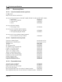
APPENDIX............................................................................................................................................................... 17.1
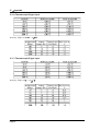
17.1.
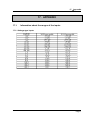
INFORMATION ABOUT THE RANGES OF THE INPUTS ........................................................................................... 17.1
17.1.1. Voltage-type inputs...................................................................................................................................... 17.1
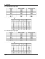
17.1.2. Thermocouple J type input .......................................................................................................................... 17.2
17.1.3. Thermocouple K type input ......................................................................................................................... 17.2
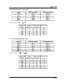
17.1.4. Thermocouple T type input .......................................................................................................................... 17.3
17.1.5. Thermocouple S type input .......................................................................................................................... 17.3
17.1.6. Thermocouple B type input.......................................................................................................................... 17.4
17.1.7. Thermocouple E type input.......................................................................................................................... 17.4
17.1.8. Thermocouple N type input ......................................................................................................................... 17.5
17.1.9. Thermocouple W5 type input....................................................................................................................... 17.5
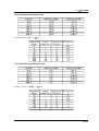
17.2.
ACCURACY OF THE THERMOCOUPLE MEASUREMENTS ...................................................................................... 17.6
17.3.
ACCURACY OF THE PT100 MEASUREMENTS ..................................................................................................... 17.7
17.4.
ACCURACY CLASS – INDEX OF CLASS................................................................................................................ 17.8
1- Important informations
1. IMPORTANT INFORMATION
Please read the following instructions carefully before using your recorder
1.1.
Cautions
Do not use the product for any other purpose than those intended.
Use normalised cables for connecting the appliance to the points of measure.
Use the power cable provided to avoid any damage to the appliance and to ensure its
measuring characteristics.
To prevent any electric shock hazard, never plug or unplug the measuring cables when
they are connected to an electric power supply.
Do not use in wet environment.
Do not use in explosive environment.
In case of failure or for the maintenance of the appliance, only qualified personnel
should be allowed to intervene. In such a case, it is necessary to use spare parts by ESCORT.
Do not open the appliance when alive.
1.2.
Security instructions
For a correct use of the appliance, it is necessary that users abide by the security measures as
described in this manual.
Some specific warnings appear all along this manual.
In case of needs, warning symbols are shown on the appliance:
This is a CLASS 1 appliance: any inner or outer electric default of the appliance in relation
with its use is evacuated to the ground that ensures the security of the user.
YOU MUST NOT unplug the protective grounding of the appliance
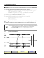
1.3.
Symbols and definitions
Page 1.1
1- Important informations
Symbols that appear in this manual:
Warning: potential danger for the user
Attention: potential danger for the appliance and/or the connected equipment
Remark: Important information
Symbols that appear on the appliance:
Danger (High Voltage): immediate corporal hazard
Attention: refer to the manual. Possibility of damages to the connected
equipment or to the appliance itself.
Grounding: reachable parts bound to the grounding of the appliance
1.4.
Conformity and restrictions of the appliance
The ESCORT 3016B, 3008B, 3004B recorders are in conformity with CEI 61010-1 (2001-
02).
See chapter "Technical specifications ".
Attention: Never set a voltage higher than the maximum admissible voltage
between the terminals and relatively to the ground.
Page 1.2
2- Presentation
2. PRESENTATION
2.1.
GENERAL
The ESCORT 3008B, ESCORT 3016B and ESCORT 3004B are programmable recorders designed
to measure and record on 6 to 36 analogical channels, voltages, currents, temperatures, etc. and 16
logical channels (event markers).
The ESCORT 3008B appliance has a built-in thermal printer for real-time signals recording. It is
suitable with 6 to 36 analogical channels isolated or multiplexed non-isolated .
The ESCORT 3016B is identical to the ESCORT 3008B but without real-time recording on paper.
It is suitable with the same kind and number of channels.
The ESCORT 3004B more compact, is the same than the ESCORT 3016B with only 6 isolated
channels in standard.
2 types of inputs are proposed:
- isolated inputs though 6-channels modules, up to 3 modules
- non-isolated differential inputs, multiplexed by 12-channel modules, up to 3 modules.
It has various functioning modes:
- a Direct mode, for acquisition printed on paper, available only on ESCORT 3008B
- a Memory mode, for acquisition on quick inner memory
- a File mode, for acquisition on inner hard drive or USB key
- a GoNogo mode, for acquisition on a pre-recorded frame.
The "operator-recorder" dialog is made easier thanks to easy-to-read menus on a wide LCD screen.
The measuring parameters are easy to program. You can program the parameters through the
keyboard and the thumb wheel on the front side, or through a mouse and a external keyboard.
The ESCORT 3008B, ESCORT 3016B and ESCORT 3004B recorders can be entirely programmed
through an Ethernet link.
Page 2.1
2-Presentation
Page 2.2
2- Presentation
2.2.
DESCRIPTION
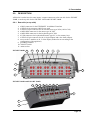
All kind of recorder have the same inputs / outputs connectors at the rear side for the ESCORT
3008B, or at the top side for the ESCORT 3016B and ESCORT 3004B.
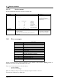
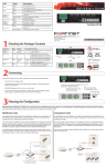
2.2.1. Rear side (or top side)
12345678-
a RJ45 connector for the ETHERNET 10/100BaseT interface
a SUB-D 9-pin connector (RS232 not used)
a SUB-D 15-pin connector for an external screen type XGA (1024 x 768)
a MINI-DIN connector for the mouse type PC PS2
a MINI-DIN connector for the keyboard type PC PS2
4 USB connectors for keyboard and mouse type PC, or for memory keys
a SUB-D 25-pin connector for the 16 logical inputs and a few alarm outputs
access to the 3 modules A, B, C of the inputs (isolated or not according to the
configuration of the appliance)
9- grounding terminal
10- ON/OFF switch
11- mains socket
ESCORT 3008B
1
3
2
4
6
5
7
9
10
8
11
ESCORT 3016B and ESCORT 3004B
9
1
2
3
4
5
6
7
8
10
11
Page 2.3
2-Presentation
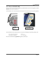
Isolated input modules include for each input 2 safety terminals :
- 1 red terminal : input "+"
- 1 black terminal : input "-"
Non-isolated differential input modules include for each input 5 screw terminals :
- 2 terminals marked + and for the voltage input
- 2 terminals marked I+ and I- for the PT100 input
- 1 grounding terminal
For all other input / output, see chapter "Inputs / Outputs".
2.2.2. Front side
The front side of the recorders includes:
- a colour LCD back-lit TFT screen
- a keyboard with function keys and menu keys
- a thumb wheel
- a set including a printing table and paper-feed for the ESCORT 3008B
2.3.
THE LCD SCREEN
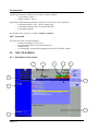
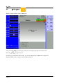
2.3.1. Description of the screen
10
1
2
3
4
9
5
8
6
7
Page 2.4
2- Presentation
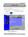
Various zones on the screen:
1- TITLE of the current menu (except for a few visualisation menus)
2- HELP: access to in-line assistance and user s manual
3- FUNCTIONS: access to the main functions with the mouse; has the same functions as
the front side keyboard
4- PARAMETERS: names of the set-up parameters and their current values
5- VALUES: possible values of the parameters currently modified; selection through a key
from F1 to F10 then modification with the thumb wheel or directly with the mouse or the
external keyboard
6- INFORMATION relative to the acquisition (validated inputs, total acquisition time,
positions of the triggers )
7- LOGICAL INPUTS: real-time status of the logical channels
8- FUNCTION : calculation functions between the channels
9- ANALOGICAL INPUTS: bargraph of the current values of the inputs
10- GENERAL STATE: mode of acquisition, date and hour, status of the acquisition or the
printing.
2.4.
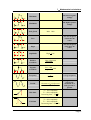
KEYS
MODE : choice of the functioning mode of the recorder: DIRECT
(ESCORT 3008B only), MEMORY, GONOGO or FILE
HELP : displays a "help" window or the user s manual
SET UP : general configuration of the appliance (language, date and
hour, alarm outputs, update of the inner software )
CHART : parameters of the printing on thermal paper (ESCORT
3008B only)
CHANNEL SET UP : access to the parameters of each channel,
access to the functions between channels
CHANNEL ON/OFF : choice of the channels to be in each
acquisition (on paper, on screen, in inner memory and on file)
DISPLAY : printing on screen of the validated channels (in
graphical forms f(t), XY or digital form), oscilloscope mode,
measure cursors, zoom, calculations
direction keys: choice of the parameter to modify
TRIGGER : triggering parameter of the acquisitions (on paper, in
inner memory or on file according to the current MODE)
REPLAY : printing on screen of the acquisitions in inner memory or
on file, measure cursors, zoom, calculations
Page 2.5
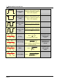
2-Presentation
START/STOP : launch of the printing on thermal paper in DIRECT
MODE on ESCORT 3008B, launch of the acquisition in any other MODE
thermal paper-feed key for ESCORT 3008B: quick advance of the paper through
continuous press
F10
2.5.
F1 to F10 keys: choice of the parameter to modify before action on the thumb
wheel
THUMB WHEEL
It makes it possible to modify the value of the selected parameter through increment / decrement. In
trace visualisation f(t), it also makes it possible to move the measure cursors on the screen.
2.6.
LOCKING THE KEYBOARD
Simultaneously triggering the
and
keys locks the keyboard. The message
Keyboard locked appears on the right top of the screen.
2.7.
USE OF A MOUSE
You can use the recorder with a mouse connected on the mouse-port PS2 or on an USB connector.
You can then use it in every parts of the screen:
- directly display the configuration of a channel by clicking on its bargraph (zone 9)
- validate / invalidate a channel by clicking on its ON/OFF indication (zone 9)
- display the configuration of the logical channels (zone 7)
- validate / invalidate the logical channels with its ON/OFF indication (zone 7)
- choose one of the functions of the recorder (zone 3)
- access the help window (zone 2)
- select a parameter to modify (zone 4)
- modify the parameter selected by clicking the propositions (zone 5): right mouse-key to
increment, left mouse-key to decrement or central wheel in both senses
- move the measure cursors in direct visualisation and memory output
2.8.
USE OF AN EXTERNAL KEYBOARD
You can also use an external keyboard connected on the keyboard port PS2 or an USB connector.
The ESC key displays the main functions of the recorder.
You can then access the functions with the keys F1 to F10 of the keyboard.
The keys Pg UP and Pg Down can be used instead of the thumb wheel to increment /
decrement the parameters.
Page 2.6
2- Presentation
2.9.
UPDATING THE INTERNAL SOFTWARE
The internal software is regularly updated with its latest evolutions. This updates are available on
our Internet site.
For the updating, copy the TAR file furnished to an USB key. Place it on one of the USB
connectors at the rear side of the appliance.
Push the
F1
key, then select the parameter line
Software update and validate with
Modify .
The internal software will automatically copy the required files in the new version.
Turn off and on after the updating is complete.
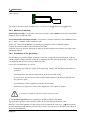
2.10. USE OF THE SUPPORT LEG OF ESCORT 3008B
The support leg under the ESCORT 3008B appliance makes it possible to use it vertically with a
little slant to the rear with better visual ease.
Attention: It is necessary to lock the support leg.
To do so, when in place, press strongly up on the sides in order to lock it on its support.
To close, pull on both sides at the same time.
Page 2.7
3
Initialisation
3. INITIALISATION and PRECAUTIONS OF USE
3.1.
ESCORT 3008B LOADING THE RECORDING PAPER
The paper used for ESCORT 3008B is provided with an end cut so that its loading is made easier.
In case of an used roll, you d better cut it again this way.
NOTE: Only one side of the paper is sensible to heat. Reverse it while loading would lead to no
printing.
Operations to proceed:
- open the door toward you
- put the axis of the paper inside the roll
- set the axis of the paper together with the roll in place at the bottom of the receptor. The axis
must be positioned inside the notches on both sides of the receptor.
The words "ref. no." must appear on the left
-
introduce the point of the paper into the slot on the stainless steel receptor
collect the paper with the point above the roll under the cutter
pull the paper sheet a few centimetres until it is well positioned
close the table.
Installation of the roll paper
A bad loading of the paper could damage the motor and the thermal head.
Special attention should be paid to it.
The recorder should always be provided with paper, for long-time direct contact with the roll
will damage the thermal head.
Page 3.1
3
Initialisation
3.1.1. Storage precautions of the records
In order to preserve the quality of the paper records, it is advisable to abide by some handling
precautions:
- never use plastic-coated pockets
- store away from light, in a dry and cool place
Paperboard-coated pockets are not advisable.
3.2.
POWER SUPPLY
The recorders work with normalised mains (see chapter "technical specifications").
It has been designed for indoor use.
MAINS CONNECTION
This appliances must be connected to the mains with the cable furnished.
SECURITY
This appliances are security class I appliances according to the CEI1010 (NF EN 61010)
classification Security regulations for electric appliances for measure, regulation and laboratory
It also should be supplied with a one-phase network according to the installation category II
(overvoltage category).
GROUNDING
This instruments should be grounded with the cable furnished.
Interrupting the grounding cable inside or outside the instrument is
FORBIDDEN and makes the appliance DANGEREOUS
3.2.1. Fuse
The protecting fuse of the mains cannot be reached by the user. In case of default of power supply,
contact the after-sales service.
Type for ESCORT 3008B supply : 5 A, 20 mm quick-fuse HBC
Type for ESCORT 3016B and ESCORT 3004B suuply : 2,5 A, 20 mm quick-fuse HBC
Page 3.2
3
Initialisation
3.2.2. Power up of ESCORT 3008B
Power-up of the recorder ESCORT 3008B is proceeded from the rear side of the appliance with the
On/Off switch to the side marked "I".
A LED marked "ON" on the front side on the keyboard will confirm the power-up of the appliance.
ON/OFF
switch
Power-up LED
After initialisation of the internal software, the recorder will display an introducing window with:
-the version of the software:
-the number of channels:
then enters automatically the
DISPLAY
Version x.y
6 ,12, 18 or more
mode (oscilloscope).
Page 3.3
3
Initialisation
3.2.3. Power up of ESCORT 3016B and ESCORT 3004B
Power-up of the recorders ESCORT 3016B and ESCORT 3004B is proceeded from the right side of
the appliances with the On/Off switch to the side marked "I".
A LED marked "ON" on the front side on the keyboard will confirm the power-up of the appliance.
Power-up LED
ON/OFF
switch
After initialisation of the internal software, the recorder will display an introducing window with:
-the version of the software:
-the number of channels:
then enters automatically the
3.3.
Version x.y
6 ,12, 18 or more
DISPLAY
mode (oscilloscope).
CONFIGURATION ON POWER-UP
On power-up, the appliances run under the latest configuration at switching-off (either normal or
after power shut-down).
If no configuration is run at power-up, contact the after-sales service
In case of wrong initial configuration, you can start the appliance with the default configuration :
you must press the key
Page 3.4
F1
until display of the initialising page.
3
3.4.
Initialisation
CONNECTION TO THE MEASURE NETWORK
3.4.1. Measure of voltage
Isolated input module: the measure of voltage is made between the red and black terminals of the
inputs through cables with security male single-pin plugs (according CEI 1010).
Non-isolated differential input module: the measure of voltage is made between the "+" and "-"
terminals of the inputs through cables on the screw-type terminal block.
3.4.2. Measure of temperature with a thermocouple
Isolated input module: you have to measure the voltage generated by the thermocouple effect
between the red and black terminals of the considered input. To ensure a right measurement,
connect directly both ends of the thermocouple cable on clamping-type single-pin plugs. Connect
the two single-pin plugs on the selected input in respect with the polarity.
Do not use male single-pin plugs for welding: the thermocouple effect would be
altered by the weld
Non-isolated differential input module: you have to measure the voltage generated by the
thermocouple effect between the "+" and "-" terminals through cables on the screw-type terminal
block.
To ensure a right measurement connect directly both ends of the thermocouple cable on the selected
input in respect with the polarity.
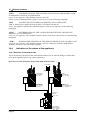
3.4.3. Measure of temperature with a PT100
Available only with a non-isolated differential input module.
The PT100 probe must be connected to the terminals I+
output).
and I-
(1mA current generator
The voltage produced by the PT100 must be measured with the teminals + and - with one of
the following scheme : 2 wires, 3 wires or 4 wires. The 4 wires mounting make the measurement
independent of the resistor value of the line.
2 wires wiring :
PT100
3 wires wiring :
PT100
Page 3.5
3
Initialisation
4 wires wiring :
PT100
You have to choose the input channel type 2, 3 or 4 wires in the Channel set up function.
3.4.4. Measure of intensity
Isolated input module: it is possible to measure intensities with a shunt between the red and black
terminals of the considered input.
Non-isolated differential input module: it is possible to measure intensities with a shunt between
the "+" and "-" terminals of the considered input.
In this case, choose the "Current" type among the parameters of the considered channel.
Connect the measure cables to the terminals of the shunt.
Collected results are directly displayed in Amperes or milli-Amperes according to the range of the
considered channel.
3.4.5. Connection of the grounding
For measuring very small voltages, problems of spurious voltages from electromagnetic fields or
common mode voltagess become all the more important than the selected sensibility is higher. Thus,
it is important that the outer wiring is made correctly.
Causes for such difficulties are various:
-
uncertainty about the true origins of the perturbing voltages and impedances when they are
generated
-
uncertainty about the spurious capacitances of the circuits and wiring
-
no access to the injection point of the common mode voltage of the network that provides
the signal to register
-
non-conformity of some appliances with the current norms
-
sometimes even ignorance of the source impedances of the signal to register
YOU SHOULD ABIDE BY THE FOLLOWING INSTRUCTIONS
1/ The mechanical ground of every appliances should be linked to the earth.
The mechanical ground of the recorder is linked to the earth through the mains cable.
However, if the other appliances in the system are not equipped the same way, you d better gather
their mechanical ground with the ground of the recorder: you can access it through a union liner at
the rear of the appliance.
Page 3.6
3
Initialisation
2/ If the source of the signal to record has a low internal impedance, you will have to use twisted
cables. If the impedance is high, you will have to use screened cables.
3/ When gathering the grounding from the various elements to the measure chain, you d better
check that there is no difference of potential in order to avoid any short-circuit. If there is any doubt,
make a measure with a voltmeter with a low charge (1k for example) between the terminals.
3.5.
Routine maintenance
The ordinary maintenance is only a cleaning of the outside of the appliance. Any other operation
requires qualified personnel.
Unplug the appliance before any intervention.
Do not let water flow into the appliance, in order to avoid any electrical discharge.
Regularly clean the recorder in respect with these instructions:
- use water and soap to clean the front and rear beards
- never use any product including benzine or alcohol that would damage the screen
printings
- wipe with a soft non-plushy cloth
- use an anti-static product to clean the screen.
3.6.
Calibration of the offsets
You can easily calibrate the inputs of the recorder for the offsets of the voltages and of the
thermocouples.
To do so:
-
make the appliance work for 20 minutes (outside temperature: 20 to 25 C)
for EVERY inputs, link the red "+" terminal to the black "-" terminal
validate every channels "ON"
-
press the key
and select the line Electronic Calibration and then the
menu key Calibration Offset
When pressing the Confirm menu key, you will launch the calibration procedure that will last
about 10 minutes.
Page 3.7
3
Initialisation
3.7.
Factory adjustement
You can easily recall the adjustement made at the factory, to repair a possible error of the
calibration coefficients :
-
press the key
and select the line Electronic Calibration and then the
menu key Reload Factory Coeff.
When pressing the Confirm menu key, you will reload the calibration coefficients stored at the
factory.
Page 3.8
3
Initialisation and precautions of use
ESCORT 3008B - Page 3.1
4
Use
4. USE
This chapter describes in details the actions of every keys of the front-side keyboard.
These actions are also available with a mouse or an external keyboard type PC (see chapter
Presentation )
The details of keys and their uses are the same for each recorder ESCORT 3008B, ESCORT 3016B
and ESCORT 3004B.
If this is not true, the kind of recorder concerned will be written in the text.
4.1.
Mode
key
Choice of the functioning mode of the recorder:
DIRECT mode: real-time paper-printing of the measured signals (ESCORT 3008B
only)
-
use: immediate writing on paper, long-term slow acquisition
possibilities: complex triggering of the writing, action after the end of the writing,
simultaneous recording in internal memory or on a file
MEMORY mode: fast acquisition in internal memory of the measured signals
-
use: short-term fast acquisition (transitory)
possibilities: complex triggering of the writing, action after the end of the writing,
simultaneous recording on file
FRAME mode: fast acquisition in internal memory of the measured signals
-
use: short-term fast acquisition (transitory) for capture of non repetitive events
possibilities: complex triggering, particularly on overrun of a pre-recorded frame
from a channel, action after the end of the writing, simultaneous recording on file
FILE mode: fast acquisition on internal hard disk or USB key of the measured signals
-
use: long-term fast acquisition (only limited by the size of the memory)
possibilities: complex triggering, action after the end of the writing, very big
amount of data of acquisition
Page 1
4
Use
4.2.
Help
key
Displays a help window or the user s notice.
After pressing
Help , pressing any other key will display the help associated with it.
Press the Help key again to exit.
If a mouse is connected to the recorder, you can also display the user s notice (requires an
integrated PDF-reader, cannot be used without a mouse).
Page 2
4
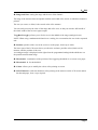
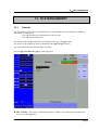
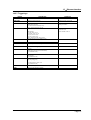
4.3.
Set up
Use
key
General configuration of the appliance, control of the alarm outputs, TCP/IP network address,
calibration of the channels, updating of the internal software.
Language: choice of the language used by the appliance
Screen shut-off: turns off the back-lighting of the LCD screen, adjustment of the delay
Configuration: initialisation of the appliance in its default configuration, saving / loading in
internal ROM memory, on internal hard disk or USB key, thermal paper printing
ATTENTION: you will loose the current configuration
Alarm A: use of the A alarm output (relay contact)
Without: no condition is controlling the contact; it remains always open
Trigger: control by association of the analogical or logical channels on several
thresholds (cf. chapter Triggering)
Paper error: control by lack of paper or opening of the door of the printing
block (ESCORT 3008B only)
In any case, the contact is open if the condition is true.
Page 3
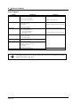
4
Use
Alarm B: use of the B alarm output (logical 0-5V output)
Without: no condition is controlling the output; it remains always low (0V)
Trigger: control by association of the analogical or logical channels on several
thresholds (cf. chapter Triggering)
Paper error: control by lack of paper or opening of the door of the printing
block (ESCORT 3008B only)
In any case, the output is low (0V) if the condition is true.
Alarm C: id. Alarm B
Date modification: setting the hour and date for the appliance
Ethernet: modification of the TCP/IP address and of the address mask
Position Max of bargraph : moving direction of the bargraph of each channel on the screen
- Right : maximum value of the channel on the right
- Left : maximum value of the channel on the left
Electrical adjustment: calibration of the offsets of the channels, return to the factory
adjustments
Software update: updating of the internal software (see chapter Presentation)
The window at the bottom of the screen shows:
- The current TCP/IP address
- The number of the current version of the internal software
- The number of detected channels
Page 4
4
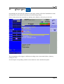
4.4.
Chart
Use
key
ESCORT 3008B recorder only.
Definition of every characteristics of the paper printing.
See chapter Direct mode for a description in details of the parameters on this page.
Page 5
4
Use
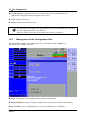
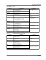
4.5.
Channels set up key
Configuration of the channels. After pressing this key, select a module, then select a channel to
access its parameters.
4.5.1. Analogical channels
Name: give a name to the channel (max. 26 characters)
Type: choice of the type of measure made on this input
- voltage, intensity, frequency or thermocouple
- direct or RMS
- value of the shunt in intensity measurement
- choice of the type in thermocouple, compensation, unit
Filter: positioning a filter at the inlet
- 10 kHz, 1 kHz, 100 Hz, 10 Hz for analogical filters
- 1 Hz, 10 s, 100 s or 1000 s for digital filters
Function: makes it possible to assign a mathematical calculation function to the considered
channel
- Without: no function.
- Change unit: modifies the unit of the measures on the channel; you can then
program a couple of dots X1, Y1 and X2, Y2 to achieve a scaling
- Calculation: available mathematical functions, associated parameters and unit
Page 6
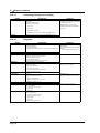
4
Use
Range and Zero: setting the range and the zero of the channel
The range is the measure that corresponds with the total width of the screen on which the channel is
printed.
The zero (or centre, or offset) is the central value of the measure.
You can settle precisely the value of the range and of the zero, so that you can take full benefit of
the whole width of the screen or paper output.
The Raz Zero
key allows you to fix the zero in the middle of the range (analogical zero).
NOTE: When using a mathematical function or a scaling, the zero matches the zero in the requested
unit.
Position: position of the zero in the screen or on the paper, from 0 up to 100%
The lower part of the LCD screen shows you the min. and max. possible values (limits) of the
measure, and the position of the zero.
A warning message is displayed on the right when the programmed analogical thresholds are out
the possible measurement range.
Threshold 1: visualisation of the position of the triggering threshold #1 on screen or on paper
Threshold 2: id. for threshold #2
Colour: allows you to modify the colour of the printing on screen
LCD Thickness: settles the thickness of the printing of the measure on the LCD screen and on
the thermal paper, from 1 up to 8 pixels
Page 7
4
Use
4.5.2. Logic channels
Change logic channels: choice of the colour and of the name of the channel on screen
Valid Event Markers: validation of the acquisition and of the printing of the logical channels
Number of markers: choice of the number of logical channels, from 1 up to 16
Height Mark.: size of the display and printing zone of the channels on the paper
Position Mark.: position of the logical channels on the screen and on the paper
Page 8
4
4.6.
Use
Channel on/off key
Choice of the channels displayed on screen, printed on paper or recorded in memory or on file.
After pressing this key, choose the inlet card (module) concerned with F1 (1st key on the right of the
screen) and select the channels you want to display on the screen, print on paper or record in
internal memory or on file.
Proceed the same way to validate the functions between channels (they are considered as
supplementary channels).
Page 9
4
Use
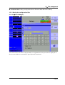
4.7.
Display
key
Real-time visualisation of the measures on the LCD screen in 1000 dots.
Screen: configuration of the display of measures on screen
- graphics F(t), graphics XY or digital display of the measures
- Full screen display of the measures only
- Modifications diagrams to organise the display on screen (see chapter
Diagrams)
- Colour to customize the colours on the screen
- vertical or horizontal sweep on screen
- display of the nouns and limits (min-max) of each channel.
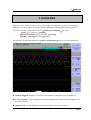
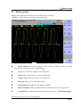
4.7.1. Display F(t) (oscilloscope mode)
The F(t) display mode allows real-time visualisation of the validated channels on screen, measures
with cursors, adding automatic amplitude and time measurements, then saving into files or printing
on paper of the acquisition after stop.
Stop: freezes the measures on screen in order to achieve measurements with cursors,
calculations, savings or printings of the measures on screen (1000 dots) in F(t) mode.
You will then have access to:
- Restart to restart the sweep
Page 10
4
-
Use
Time cursors to display the vertical cursors (2) in order to make measures in
the display; move the cursors by selecting 1 or 2 then turning the thumb wheel, or
click on the cursor with the mouse if it is connected
Voltage cursors to display the horizontal cursors (2) to make amplitude
measures on the display; proceed as for the time cursors to move them. You van
also change the range / zero to expand and move your measure on the screen.
Time base: changes the base of the sweeping time of the F(t) display, from 100 s/div up to
10mn/div; each division includes 100 dots, i.e. a sampling frequency from 1 Mech/s (1 s) up to
0.16 ech/s (6 s).
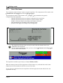
In F(t) mode (oscilloscope mode),the sweeping is in triggered
bases < 50 ms/div, and in scrolling mode above.
mode for time
In triggered mode, the 4 following parameters set the trigger of the displayed acquisition. These
parameters are not available in scrolling mode:
Choice: choice of the triggering channel
Front: active front of triggering
Level: vertical position of the trigger between -100% and +100%
Position Decl.: horizontal position of the trigger between 0 and 10 divisions
In triggered
channel.
mode, the position of the trigger is marked with a small triangle on the selected
Validation: choice of the displayed channels on screen; identical as the main key Valid.
channels
Calculation Math.: adding automatic measurements on screen; click Add to add a measure
on the screen and Delete to delete one; see chapter Mathematical calculations .
- # Param: choice of the measure for modification
- Channel: choice of the channel on which you will assign the measurement
- Type of function: Amplitude for amplitude measurements, Time for time
measurements or Calculation for measurements of average values and effective
values RMS
Page 11
4
Use
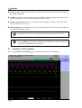
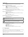
4.7.2. Display XY
The XY display mode allows you to display the validated channels in real time on screen, one
versus the others.
One of the channels defines the extension on the horizontal axis; the other channels define the dots
on the vertical axis.
Grid pattern: to customise the grid pattern of the XY display
You can select, either a predefined grid pattern with selection of the colour, either a customised
grid pattern (copied from an USB key or ftp to the hard disk)
This BMP file size is 640*640 pixels with 24 colours, the predefined grid (gridxy.bmp) is in the
base directory of the hard disk.
You can use paint (from Microsoft) or a free software (paint.NET,gimp word etc..)
to create the BMP file.
With paint software, to create a line you must give the two points coordinates.
Theses coordinates are displayed on bottom left corner of the window.
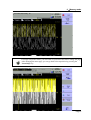
Point or vector: display the point or the line between successive points .If the channel
frequency is higher than the display point frequency (0.1Hz) you can have a false display
X channel: choice of the channel on the horizontal axis (sweep)
Y channel:
-
One: only one way on the vertical axis; choice of this channel on the following
parameter
Several: access to the validation of the channels on the following parameter
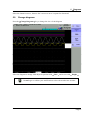
4.7.3. Digital display
The Digital display mode allows you to display the digital values of the validated channels in real
time on the screen.
No action is possible in this mode.
4.8.
Direction keys
They move the reverse video zone on to the parameter to modify.
You can modify the parameters with the thumb wheel, with a mouse if it is connected, or with an
external keyboard.
Page 12
4
4.9.
Trigger
Use
key
Programming the start and stop conditions of the paper printing in ESCORT 3008B Direct mode,
the acquisition of the channels in Memory, File and GoNogo modes.
Choice of the actions after acquisition or printing and validation of the saving in real time.
The programming of the triggers is different according to the current mode (Direct, Memory,
GoNogo or File).
See the chapter corresponding with the current mode for a more detailed description.
Page 13
4
Use
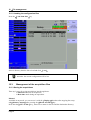
4.10.
Replay
key
Display on screen of the acquisitions available in internal memory or in files on hard disk or USB
key.
This function has the same commands as the
Display
function.
The only difference is the Blocks and Files command that allows you to select the memory
block (zone in the internal memory divided in blocks) or the file to display.
Blocks and Files:
- Number block: number of the memory block to display
- Load file: choice of the file to display
- Load configuration: copy of the configuration of the acquisition being displayed
into the current configuration (validated channels, ranges )
- Save Disk: saving the current display into a file
- Reference: comparison of blocks versus a reference block (Memory mode); the
traces of the reference block are shown in dots
Page 14
4
Use
When the size of the acquisition to display is big, collecting and displaying the dots may
be long.
Displaying is then achieved in 2 phases:
- a quick phase that displays the envelope of the acquisition: some dots may not appear
- a phase where all the dots of the acquisition are displayed: an assessment of the percentage of
advance is displayed at the bottom of the screen.
4.11.
Start/Stop
key
This key has various effects according to the current mode of the appliance.
ESCORT 3008B Direct mode: launches the printing on paper if its triggering is in manual start;
else, sets the appliance in wait mode for the triggering Start condition.
Memory mode: launches the acquisition in internal memory and sets the appliance in wait
mode for the triggering Start condition.
GoNogo mode: launches the acquisition in internal memory and sets the appliance in wait mode
for the triggering Start condition.
File mode: launches the acquisition on file and sets the appliance in wait mode for the triggering
Start condition.
In any case, to stop recording before the triggering Stop condition, you only have to press the same
key Start/Stop once again.
In Memory, GoNogo or File modes, the appliances switches automatically to display of
the current acquisition.
At the top left of the screen, it will then appear:
- the number of the current block if required
- the current sampling rate
- the status of the acquisition (waiting triggering start, proceed xx%, )
- the opening of a saving file if required
- a bargraph where you can recognise the percentage of achieved acquisition and
the percentage of displayed acquisition.
Page 15
4
Use
4.12.
Paper-feed key
ESCORT 3008B paper-feed as long as you press the key.
Page 16
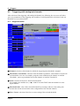
5
Diagrams
5. DIAGRAMS
Diagrams are the partition of the screen or of the width of the paper sheets in zones of printing or
displaying in order to gather or separate channels and improve the legibility of the acquisitions.
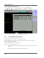
You can access this configuration with the Modification Diagrams key from:
Paper key, parameter Reticule
Direct visualisation key, parameter Screen
Memory output , parameter Screen
The appliance switches automatically to Direct visualisation
to show you your organisation:
Number Diagram: number of divisions of the screen or of the paper up to maximum 12
V.Log separated: prints or displays of the logical channels superimposed to the diagrams or in
a separate diagram
Height V.Log: size for displaying the logical channels, from 3 up to 250 mm
Page 1
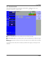
5
Diagrams
Position V.Log: position of the display of the logical channels above or below the diagrams of
the analogical channels
Validate: validation of the previous parameters (Number diagrams, height and position of the
logical channels) in order to take the modifications into account
Position of the channels: place of the channels in the diagrams; select the channel you want
and press the arrows to move it
Change Diagrams: modification of the size of each diagram; select the channel you want and
enter its start and height in mm.
Don t forget to validate your modifications to have them taken into account
After selection of the number of diagrams or validation of the logical channels,
press Validate ; the appliance dispatches the diagrams on the screen (and also
on the paper) automatically in equal sizes
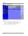
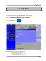
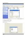
5.1.
Positions of the channels
Press the Position of the channels key to dispatch the channels in the diagrams.
Page 2
5
Diagrams
Select the channel to move, then use the 2 arrows to move it upward or downward.
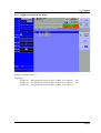
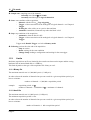
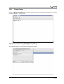
5.2.
Change diagrams
Press the
Change Diagrams
key to change the size of each diagram.
Select the diagram to change, then adjust its position with Start
and its size with Height .
Don t forget to validate your modifications to have them taken into account
Page 3
6
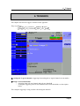
Triggers
6. TRIGGERS
This chapter describes the triggers available in this appliance.
They are used by:
Set up key, parameters Alarm A, B and C
Trigger key, parameters Start and Stop
Analogical / Logical channels: triggering from analogical or logical channels (event marks)
Single / Several thresholds:
- triggering from only one channel and only one threshold
- or complex triggering from several channels and several thresholds; see description
below.
This complex triggering is only possible with analogical channels.
Page 1
6
Triggers
6.1.
Triggering with analogical channels
After selection of the triggering with analogical channels, the following line on screen will allow
you to set parameters for the triggering start condition. It will depend on the selection of only one
threshold or of several thresholds.
6.1.1. Single threshold
Channel: selection of the channel on which the triggering start threshold is assigned
Threshold 1 / Threshold 2: selection of the threshold to parameter; each channel is tested with
two thresholds. You can, for example, program a start condition on the channel A1 and the
Threshold 1, and a stop condition on the same channel A1 and the Threshold 2.
Front: selection of the active front for the threshold
For example, the condition A1 (s1 ): 0.000 V becomes TRUE when the channel A1 turns
higher than 0V.
Threshold value: value of the selected threshold in percentage and true value (taking into
account the current unit and scale in the configuration of the selected channel)
Fine / Coarse: selection of the fine or coarse setting of the selected threshold
Page 2
6
Triggers
6.1.2. Several thresholds
After selection of a trigger on several channels and thresholds, a
program the condition for a complex trigger.
Call key allows you to
One of Thresholds (or): the first conditions achieved validates the trigger
All Thresholds (and): every conditions must be achieved simultaneously to validate the trigger
Slope (or): triggering according to the slope of the signals; the first condition achieved validates
the trigger
You will then be able to add, delete or modify any condition of the trigger by selecting one of the
conditions.
Page 3
6
Triggers
6.1.3. Trigger according to thresholds
Example: the trigger above is
Triggering if
Channel A1
Channel A2
Channel A2
Channel A3
increasing and equal to the threshold S1, value 0.000V
increasing and equal to the threshold S1, value 0.500V
increasing and equal to the threshold S2, value 0.500V
decreasing and equal to the threshold S1, value 0.500V
The same analysis is worth for the AND trigger (every thresholds).
Page 4
OR
OR
OR
6
Triggers
6.1.4. Trigger according to the slope
Example: the trigger above is
Triggering if
Channel A1
Channel A2
Channel A3
increasing with a positive slope: 2.000V on a 1s period
increasing with a positive slope: 0.500V on a 1s period
increasing with a positive slope: 0.500V on a 1s period
OR
OR
Page 5
6
Triggers
6.2.
Triggering with logical channels
After selection of the triggering with analogical channels, the following line on screen will allow
you to parameter the triggering condition.
The 16 logical channels can be used in the triggering instruction:
-
Page 6
either active in state 0 (lower than 1.6 volt)
or active in state 1 (higher than 4.0 volts)
or not used
7
Mathematical calculations
7. MATHEMATICAL CALCULATIONS
You can make mathematical calculations on achieved acquisitions.
You can access them with the Display function and the Replay
displayed on screen.
7.1.
Definitions
Press the
Math key.
function if an acquisition is
Add: add a mathematical calculation
Remove: delete one of the displayed mathematical calculations
#Param: selection of the number of the displayed calculation for modification
Channel: selection of the channel on which the selected calculation of # param will be
made
Function Type: type of calculation made in the selected calculation of # param
Page 1
7
Mathematical calculations
Function: selection of the calculation function made in the selected calculation of #Param
You can choose among 20 different mathematical calculations in 3 categories:
- Amplitude: min values, max values, peak to peak, base, highest, amplitude, overshoots
- Time: frequency, period, increasing time, decreasing time, positive widths, negative
widths, positive and negative duty factors
- Calculation: average values, cyclic average, cyclic RMS and effective RMS
You can display up to 5 simultaneous calculations on screen.
The display is made in rectangles above the diagrams where are also specified:
- the number of the channel (with its colour)
- the type of calculation
- the value of the calculation
In Display function, the calculations are made in real time and the display is updated every 300
ms.
The calculation is made on the 1000 dots displayed on screen. Thus, the time resolution is 0.1 %.
The calculations can concern every channels. However, you cannot assign calculations:
- on the supplementary channels that are functions of other channels
(example F3=A1+B2)
- if the channels have been recorded (validation ON/OFF)
7.2.
Types of calculations
Max
High
90 % Ampl
Ampl
Peak_peak
10 % Ampl
Low
Min
Rise time
Explicative scheme
Page 2
Math.
Functions
Falltime
Calculation
Remarks
7
The lowest negative
Minimum
voltage
The highest positive
Maximum
Peak_Peak
T1
Max Min
The most frequent
value below the
centre
High
The most frequent
value above the
centre
High
Low
Positive
overshoot
Max High
100
Amplitude
Negative
overshoot
Low Min 100
Amplitude
Frequency
1
Period
Average frequency
Period
Duration of N full period
N
Average duration of
a total cycle,
calculated on as
many periods as
possible
Rise time
T1 = 10% Amplitude
T2 = 90% Amplitude
Increasing time = T2 T1
Fall time
T1 = 90% Amplitude
T2 = 10% Amplitude
Decreasing time = T2 T1
T2
T2
voltage
Low
Amplitude
T1
Mathematical calculations
Page 3
7
Mathematical calculations
Positive pulse
width
Measure of the duration of the
1st positive impulsion. Made at
50% of the amplitude
Measure of the duration of the
Negative pulse st
1 negative impulsion. Made at
width
50% of the amplitude
Positive cycle
time
Negative cycle
time
Average
duration of positive impulsion
period
duration of negative impulsion
p iode
1 N
Vi
N i 1
N: total number of dots
Moy
N2
1
Vi
N 2 N1 i N 1
Cyclic average
N2-N1: number of dots between
complete periods
Moy
RMS
Cyclical RMS
Page 4
RMS
RMS
1 N
Vi 2
N i 1
N2
1
Vi 2
( N 2 N1 ) i N 1
Calculation on the
whole graphic
window
Calculation on as
many periods as
possible
Calculation on the
whole graphic
window
8
Direct mode
8 DIRECT MODE
This chapter describes the Direct mode of the ESCORT 3008B recorder, designed to plot in real
time on thermal paper the measures achieved on the channels.
This mode does not exist on ESCORT 3016B and ESCORT 3004B.
You can trigger the start and stop of the plotting under various conditions.
You can activate a simultaneous saving of the measurements in an internal memory or in a file.
8.1.
Configuration of the plotting
Press the
Chart key.
Definition of every characteristics of the paper plotting.
Page 1
8
Direct mode
Mode: choice of the printing mode
- F(t): printing a graph versus the time
- Numeric: printing digital values of the measures in a table
Paper speed: printing speed
- internally rated feed from 1 mm/h up to 200 mm/s
- externally rated feed through the logical channel 16
Grid Pattern: definition of the grid pattern plotted on the paper
- none, every 5 mm, 10 mm or with an integer number of divisions
- fine or wide, i.e. with or without subdivisions
- access to the Change Diagrams to organise the presentation of the channels
on the paper (see chapter Diagrams)
Title: giving a title (max. 124 characters) for printing. It will appear at the top of the
paper sheet.
Time: type of time reference, printed at the beginning of the plotting and with every
annotation
- absolute: real-time hour and date
- relative: setting to zero at the beginning of the plotting, printing the elapsed time
after each new annotation.
Boundary: possibility to write the limits of each channel (min-max) and the position of
zero at the end of the plotting
Annotation: possibility to have annotations while printing
- no, at the beginning of the plotting, on an alarm or on a length of paper
- made of the name, the number, the current value or the range of the channels
Write Message: you can also write a text directly on the paper
- after entering your text, press the Write key: the text will be immediately
plotted on the paper
- if the plotting has begun, it will be paused and will start again when the line is
written.
Plot a BMP file: you can write a file under BMP format (bitmap windows). The BMP
file must be single colour (height 2000 pixels maximum).The must be on the hard disk,
and can be copied with an USB key or via ftp link
.
Page 2
8
8.2.
Direct mode
Triggering plotting
Press the
Trigger key.
Programming the start and stop conditions of the plotting.
Selection of the actions after the plotting and validation of the saving in real time.
Mode: selection if the printing mode
- F(t): printing a graph versus the time
- Numeric: printing digital values of the measurements in a table
Paper speed: printing speed
- internally rated feed from 1 mm/h up to 200 mm/s
- externally rated feed through the logical channel 16
Speed before Trigger: printing speed before the start trigger; possible if the start trigger
is not Manual
Start: condition for starting the plotting
- Manual: with the Record key
- Trigger: with an association of the analogical or logical channels
see Chapter 6 Trigger
- Wait for: after a delay or at a precise date and time
Page 3
8
Direct mode
Stop: condition for stopping the plotting
- Manual: with the Record key
- Trigger: with an association of the analogical or logical channels
see Chapter 6 Trigger
- Wait for : after a delay or at a precise date and time
- Paper length: after writing a programmed length of paper
After end of plot: action after the end of the plotting; only possible if the start and stop
triggers are not Manual
- Stop: no action
- Rearm: waiting for the start trigger
- Change Setup.: loading a configuration and waiting for the start trigger
Save Data: simultaneous saving of the measurements in internal memory or on a file
- No save: no simultaneous saving
- Memory: recording in internal memory
- Acquisition period: sampling speed of the channels
- Blocks: dividing the internal memory into blocks
- File: recording on a file
- File name: place and name of the saving file
- Acquisition period: sampling speed of the channels
See chapter File mode to know the limitations of the file recording
Trigger: condition for stopping the simultaneous saving in internal memory only
- Direct: the same as for paper printing
- Manual: with the Record key
- Trigger: with an association of the analogical or logical channels
see Chapter Trigger
- Pre-triggering: position of the trigger in the memory (in the block)
Following: actions after the end of the simultaneous acquisition into the memory
- Save on file: saving the acquisition into a file
- Plot: writing the simultaneous acquisition into the memory
- Rearm.: reloading the writing; waiting for the start condition again
Page 4
If a speed before start has been programmed, the paper will be fed at this rate
while waiting the trigger.
The user can urge the trigger at any time by pressing the "Start/Stop" key again
while waiting for the start
While plotting, pressing this key will stop the plotting
In case of power failure while plotting, the recorder will start again in the same
status (waiting or writing)
8
8.3.
Direct mode
Rearmament of the plotting
In rearm. mode, waiting for the start of the plotting is automatically reloaded when the stop
conditions arouse.
To interrupt the cycle, you only have to urge the stop of the plotting by pressing the "Start/Stop"
key while plotting.
8.4.
Writing data
At the beginning of each plotting are written the date, the hour, the programmed title at the top of
the paper sheet.
The number of each channel is written on the plotting.
8.5.
Example of plotting program
We would like to trigger the plotting of the channel 1 when the channels 3 and 4 are both above
50% of the full scale.
Before triggering, the plotting will be made at low rate (5 mm/s).
After triggering, the recorder will draw 50 cm paper at 50 mm/s, then the configuration "Config 3"
will be loaded.
Program:
in DIRECT
mode with the
MODE key
Chart key:
Here, you can define all that concerns the plotting on paper
In our case, only 1 diagram on 250 mm
Here, you could give the plotting a name and call the writing of annotations.
Trigger key
Paper speed : 50 mm/s
Start : Trigger
Speed before trigger : 5 mm/s
Analogic channels
Several thresholds
Definition of the start condition on the following line:
Call :
Every thresholds (AND)
- following line: add a threshold
- channel A3, threshold 1, increasing front, Add
- adjust the threshold 1 at 50%
add a threshold
- channel A4, threshold 1, increasing front, Add
- adjust the threshold 1 at 50%
Stop : Paper length
- paper length: 500 mm
After end of plot : Change Config.
Configuration : in our case: "3"
Save Data : in our example, we will leave no
Channels on/off key
Page 5
8
Direct mode
module A
Channel A1
ON
Channels set up key
- select the range and the zero so that the channel is centred on the paper
Recording:
Press the "Start/Stop" key.
The writing begins at a 5mm/s rate and waits for the trigger start condition.
When both channels A3 and A4 have reached the programmed threshold on increasing, the trigger
start is validated.
The writing turns to a 50mm/s rate and keeps on 50 cm, thus 10 s.
After these 10 seconds, it turns directly to the configuration 3.
When the new configuration is ready, the recorder proceeds as if the user had pressed the
"Start/Stop" key.
Page 6
9
Memory mode
9. MEMORY MODE
This chapter describes the Memory mode designed to record in real time into the internal memory
the measures achieved on the channels.
You can trigger the start and stop of the plotting under various conditions.
You can activate a simultaneous saving of the measurements in an internal memory or in a file.
9.1.
Configuration
Press the
and triggering of the acquisition
Trigger key.
Definition of the acquisition into internal memory.
Sample Rate: sampling rate of the channels
- internally rated from 1 s to 20 min
- externally rated through the logical channel 16
Blocks: division of the internal memory into blocks
- 1, 2, 4, 8, 16, 32, 64 or 128
Page 1
9
Memory mode
-
Raz Blocks: deleting all the blocks: the current block is the #1 block
Start: start condition of the acquisition
- Manual: with the F2 key Urge triggering
- Trigger: with an association of the analogical or logical channels - see Chapter 6
Trigger
- Waiting for: after a delay or at a precise date and time
- Automatic: immediate; automatic stop when the block is full
Pre-triggering: definition of the position of the start trigger in the acquisition
- pre-trigger and post-trigger of the acquisition (before or after Start); and if the trigger
is allowed during pre triggering time
Stop: stop condition of the acquisition
- Automatic: when the block is full
- Trigger: with an association of the analogical or logical channels - see Chapter 6
Trigger
Trigger mode Double Trigger: see below
Real-time Saving: simultaneous recording of the acquisition into a file
- place and name of the saving file
- maximum length of the file
Impossible is displayed when the saving capabilities are overrun: reduce the
sampling rate or the number of channels
See chapter File mode to know the limitations of the file recording
Following: actions after the end of the acquisition
- Save on file: saving the acquisition into a file if the real-time saving is not validated
(or is impossible)
- Plot: plotting the acquisition
- Stop: no action
- Rearm: waiting for the start condition
- Change setup: loading a configuration and waiting for the start trigger
9.2.
Sampling period
When the frequency of the input signals is too high to record them in Direct mode, you must put the
measured signals into memory at a high acquisition rate: this is the Memory mode
Sampling consists in reading the instant value of a signal at regular time intervals: each of these
values is stored in a memory.
Page 2
9
Memory mode
So that the acquisition of a periodic signal is convenient, you should select a sampling period that is
compatible with the frequency of the signals at the input terminals of the recorder.
A
9.3.
10-dot-per-signal-period accuracy is minimum for a convenient plotting
Internal memory, blocks
You can divide the available memory of the recorder into blocks that will be filled one after the
other at each acquisition.
The amount of data of acquisition is worth N / (B * V)
N = total memory
B = number of blocks
V = number of channels to collect
Example: memory: 32 Mbytes, 16 blocks and 3 channels "ON"; you will have
N = 32,554,432 / (16 * 3) = 699,050 bytes/channel
Any new acquisition will be placed automatically into the first free block available (in increasing
sense).
When every blocks are full, a new acquisition will shift the previous block N into the block N-1; the
1st block will be lost.
The new acquisition will then take the place of the last block.
9.4.
Triggering position
The acquisition into a memory block is based on the system of the rotary memory :
- the memory starts filling from the start condition
- the memory keeps on filling as long as the stop condition is not valid; if the memory is
full, the filling restarts from the beginning of the memory zone (block)
Thus, the memory block always contains the N last samples.
The user can choose the moment when the samples in the memory will be frozen: to do so, he will
define a delay between the triggering moment and the beginning of the effective transfer into
memory.
This delay can be positive or negative. The samples in memory can thus be either before or after or
on both sides of the triggering moment.
We can also not inhibit the trigger during the pre trigger phase : this allow to test the trigger
condition during the pre trigger phase and make the trigger function even if the pre trigger time isn t
passed.
MEMORY
MEM ORY
T RIG GERIN G
TRIGGERING
- 50 %
MEMORY START
+ 50 %
MEM O RY START
Page 3
9
Memory mode
Transfer to memory with a -50% delay
relatively to the beginning of the memory
9.5.
Transfer to memory with a +50% delay
relatively to the beginning of the memory
Double Trigger mode
In this mode, you will use a start trigger and a stop trigger.
You will thus record the measurements between those two triggers.
The acquisition will automatically stop:
- when the stop condition is valid
- or when the memory block is full
An information window will summarise the general configuration of the acquisition :
- channels and functions between the channels validated for the acquisition
- number of dots per channel (according to the number of blocks)
- total acquisition time (according to the acquisition rate)
- position of the trigger (according to the pre-triggering)
9.6.
Recording
You launch the data acquisition by pressing the Start/Stop
key.
It will appear at the top left of the screen:
- the number of the current block if required
- the current sampling rate
- the status of the acquisition (waiting for triggering, filling xx% )
- the opening of a saving file if required
- a bargraph where you can recognise the percentage of achieved acquisition and the
percentage of displayed acquisition.
The menu key F1
Stop
allows you to stop the current acquisition.
If the acquisition time of the record is less than 2 minutes, the whole acquisition will
be displayed. You won t be able to exit this page then: the acquisition must be stopped
before you can change of menu.
Page 4
9
Memory mode
For longer acquisition times, you can zoom on a portion of the data or change the page.
After changing the menu page, you can go back to the acquisition by pressing the
"Start/Stop" key.
Page 5
9
Memory mode
Supplementary menu keys:
Display:
Total: the whole data memory is displayed and updated during the acquisition.
Partial: only a part of the data memory is displayed; the display is frozen; only
the bargraph and the percentage of achieved acquisition let you know the status
of the acquisition; you have then access to the time and zoom cursors.
You cannot display another block than the current one. You cannot plot or save to file
the acquisition as long as it is not over.
At the end of the acquisition process, the appliance switches automatically to memory display
function Replay .
Page 6
9
9.7.
Memory mode
Memory output
Display of the acquisitions available in the internal memory or in files.
Possibility to launch the paper printing of the acquisitions.
Blocks and files: choice of the memory block or of the file to display; if there is no valid
block, the only existing menu key is Load file .
Screen: type of display, diagrams; see chapter Use
Time cursor: vertical cursors, zoom; see chapter Use
Voltage cursor: horizontal cursors; see chapter Use
Full page: display of the whole data memory
Channel On/Off: validation of the channels ON/OFF
Math. calculation: adding automatic measurements on the screen; see chapter Use
Setup plotting: configuration of the plotting of the acquisition; Launch plotting
key
At the top left of the screen, it will then appear:
Page 7
9
Memory mode
-
Page 8
the number of the displayed block
the sampling rate
the date of the trigger
the number of dots per channel in this block
a bargraph where the filling percentage of the block and the position of the
trigger are displayed.
10
Go/Nogo mode
10. GO/NOGO MODE
This chapter describes the Go/Nogo Mode designed for the real-time recording into the internal
memory the measures achieved on the channels.
You can trigger the acquisition under various conditions. You can stop it when measures exceed a
previous acquisition defined as a Frame.
You can activate a simultaneous saving of the measures on a file.
10.1.
Configuration and triggering of the acquisition
Press the
Trigger key.
Definition of the acquisition into internal memory with frame.
Channels for Go/Nogo: channels to compare to the frame; access to the definition of the frame
Page 1
10
Go/Nogo mode
Sample rate: sampling rate of the channels
- internally rated from 1 s to 20 min
- externally rated through the logical channel 16
Blocks: division of the internal memory into blocks
- 1, 2, 4, 8, 16, 32, 64 or 128
- Raz Blocks: deleting all the blocks: the current block is the #1 block
Start: start condition of the acquisition
- Manual: with the F2 key Urge triggering
- Trigger: with an association of the analogical or logical channels - see Chapter 6
Trigger
- Waiting for: after a delay or at a precise date and time
- Automatic: immediate; automatic stop when the block is full
Pre-triggering: definition of the position of the start trigger in the acquisition
- pre-trigger and post-trigger of the acquisition (before or after Start); see chapter
Memory Mode
Real-time Saving: simultaneous recording of the acquisition into a file
- place and name of the saving file
- maximum length of the file
Impossible is displayed when the saving capabilities are overrun: reduce the
sampling rate or the number of channels
See chapter File mode to know the limitations of the file recording
Following: actions after the end of the acquisition
- Save on file: saving the acquisition into a file if the real-time saving is not validated
(or is impossible)
- Plot: plotting the acquisition
- Stop: no action
- Rearm.: waiting for the start condition
- Change Setup: loading a configuration and waiting for the start trigger
10.2.
Creation of the frame
Make a normal acquisition or display a previously recorded file with the function Memory
output .
In the page Trigger , select the parameter
frame then Modify .
Channels for Go/Nogo then
Visualize the
The appliance will then display the current frame. It appears as 2 curves (a min and a max curve)
around the channel selected as a reference for the frame.
Page 2
10
Go/Nogo mode
Both curves have been saved in non-volatile RAM internal memory.
Return: returns to the previous page, the frame won t be changed
Block number: allows you to select the reference block
Channel: allows you to select the reference channel
DX and DY: allow you to plot the 2 curves min and max
Begin and End: limits of the memory space used for the trigger stop test
Save: as soon as the frame is correct, you can save it into ROM internal memory.
You cannot save a frame on a file. To keep a frame on a file, save the block and the
channel that will allow you to recreate the frame for a new use.
Page 3
10
Go/Nogo mode
10.3.
Use of the frame
The comparison with the frame is used to stop the acquisition. This comparison will be made on the
Channels for Go/Nogo selected in the Trigger page.
The information window at the bottom of the Trigger page summarises the general
configuration of the acquisition:
- channels and functions between channels validated for the acquisition
- channels and functions between channels compared with the frame
- number of dots per channel (according to the number of blocks)
- total acquisition time (according to the acquisition rate)
- position of the trigger (according to the pre-triggering)
The comparison with the frame can only be made when the channels have been
validated for the acquisition.
An error message will display when you have selected Channels for Go/Nogo that
have not been validated (ON).
The acquisition is made as previously (see chapter Memory mode).
When the memory block is full, the appliance will check that every collected dots on the frame
channels are the 2 min and max reference curves of the frame.
If every dots are within the frame, the acquisition will start again (in the same block). Else, the
acquisition will stop.
Page 4
11
File mode
11. FILE MODE
This chapter describes the File mode designed for real-time record on a file of the measures
achieved on the channels.
You can trigger the start and stop of the plotting under various conditions.
11.1.
Configuration and start of the acquisition
Press the
Trigger key.
Definition of the acquisition into a file.
File name: place and name of the acquisition file
- directory (place) of the acquisition file
- name of the acquisition file
- type of the acquisition file: binary or text
Page 1
11
File mode
Sample rate: sampling rate of the channels
- internally rated from 1 s to 20 min
- externally rated through the logical channel 16
Start: start condition of the acquisition
- Manual: with the F2 key Urge triggering
- Trigger: with an association of the analogical or logical channels - see Chapter 6
Trigger
- Waiting for: after a delay or at a precise date and time
- Automatic: immediate; automatic stop when the block is full
Stop: stop condition of the acquisition
- Automatic: when the block is full
- Trigger: with an association of the analogical or logical channels - see Chapter 6
Trigger
Trigger mode Double Trigger: see below Memory mode
Following: actions after the end of the acquisition
- Stop: no action
- Ream: waiting for the start condition
- Change Setup: loading a configuration and waiting for the start trigger
11.2.
Limits
Real-time acquisitions on file are limited by the transfer rate between the inputs and the saving
hardware liek an internal hard disk or a USB key.
This limit depends on the type of the acquisition file: binary or ascii.
11.1.1.Binary file
The maximum transfer rate is 1,200,000 bytes/s (1.2 Mbyte/s).
In order to know the number of channels that you can record for a given acquisition period, you
have to calculate:
number of channels = 1,200,000 x acquisition period
example:
acquisition period: 10 s
number of channels = 1,200,000 x 10 s = maximum 12 channels
11.1.2.Ascii file
The maximum transfer rate is 1,000 bytes/s (1.0 Kbyte/s).
The minimum acquisition period is 1ms.
In order to know the number of channels that you can record for a given acquisition period, you
have to calculate:
number of channels = 1 000 x acquisition period
Page 2
11
example:
File mode
acquisition period: 10 ms
number of channels = 1 000 x 10ms = maximum 10 channels
Impossible is displayed when the saving capabilities are overrun: reduce the
sampling rate or the number of channels
Page 3
12
File management
12. FILE MANAGEMENT
12.1.
General
For all possible types of files, the appliance has an internal hard disk and can admit an USB key,
which makes it possible to:
- save and load the total configuration of the recorder
- save and load an acquisition.
The names of the configuration files are identified with a *.CNF extension.
The names of the acquisition files are identified with a *.REC extension.
You can create directories and save files into them.
Press the
Create Directory
key when suggested.
HD / USB key: read / write on internal hard disk or USB key (if it has been connected at the
power-up of the appliance)
Page 1
12
File management
Create directory: creation of a directory; you can then enter its name thanks to an
alphanumerical keyboard that is displayed on the screen
Goto: change of directory
Delete: deletes the selected directory
It is advised to work under a directory, and not on the root of the hard disk. It is easier
for files organisation and for files deletion.
When you delete a directory, all file under this directory are deleted
12.2.
Management of the configuration files
The management page for the configuration files is associated with the "Setup" key.
Their name has a ".CNF" extension.
Reset: initialisation of the appliance under standard configuration
Internal memory: saving / loading a configuration in internal non volatile RAM memory
Save to disk: saving a configuration into a file on the hard disk or an USB key
Page 2
12
File management
Load from disk: loading a configuration from a file on the hard disk or an USB key
12.1.1.Saving the configuration files
Press the
Save to disk key
You can then enter the name of the file thanks to an alphanumerical keyboard that is displayed on
the screen or thanks to an external PC-type keyboard if connected.
Page 3
12
File management
12.1.2.Loading the configuration files
Press the
Load from disk key
Select a directory then the file to load and click
Load .
Attention: the current configuration will be lost
12.3.
Management of the acquisition files
12.1.3.Saving the acquisitions
There are 2 ways for saving acquisitions into the appliance:
- in Manual mode after an acquisition
- in Real time mode during an acquisition.
Manual:
Available in any mode; you can access it with the Display functions after stopping the sweep
and Memory output after pressing the Blocks and Files key.
Press then the Save to disk key , then write a name for the file and the destination directory.
Page 4
12
File management
Real time:
Available in Direct, Memory and Go/Nogo modes after validation of Saving Real time
File mode is based on this real-time saving).
(the
As soon as the recording is launched, the appliance saves the samples into the file. The file will be
closed as soon as the acquisition is over.
If the acquisition is waiting for a start trigger, the appliance records into the file every dots
before this trigger. After stopping the acquisition, this file will thus include more dots than
the memory block that has been used for the acquisition.
In both cases, Manual or Real-time recording, the date of the file will be the closing date of the file.
Name of the files: the name of each file is made of 12 characters and a number made of 4 digits.
The appliance will automatically increment this digit at each recording.
Only the validated channels (i.e. in ON position; see chapter Use) will be recorded into the file.
Before writing the file, an information window will remind you of the channels that will be saved
and of the number of dots per channel.
The file is made of:
-
a heading including the data required for later correctly loading the file (the
configuration of each channel, the sampling rate, etc.)
-
the N samples (1 sample = 2 bytes per channel).
Page 5
12
File management
12.1.4.Loading the acquisition files
Press the
Load file
key from the
Replay
function, then
Blocks and files .
Select the place and the name of the file to load to display it on screen.
12.4.
PC SOFTWARE FOR ANALYSIS
Acquisition files can be transferred to a PC computer for analysis.
ESCORT_VIEW software is provided on a CD-ROM together with the appliance. It makes it
possible to display the recorded files.
It works under WINDOWS 95,98, NT, XP, 2000.
Using the files on a PC is made in two times:
-
transfer of the files to the PC thanls to the FTP protocol with your Internet navigator, for
example
-
display of the files thanks to the ESCORT_VIEW software.
Page 6
12
File management
12.1.5.File transfer with FTP
Use of window explorer (recommended)
Click tools then select connect a network
Click open a storage session or a network server
In internet network address put ftp://address IP of my recorder
address IP of my recorder can be for example: 135.150.12.2
You can give a name to this network connection in network favourite
Use of a navigator (internet explorer, firefox, opera etc..)
Launch your Internet navigator and write the connection address (see chapter Setup):
ftp://
then press Enter
followed with the IP address of your recorder
on your computer.
You can then access the directories of your recorder that include the acquisition files:
- HD: main directory on the internal hard disk of your appliance
- UsbKey: USB key if it is connected to your appliance
After selection of the directory where you have recorded your acquisitions, you can rename, move,
copy or delete them.
Transfer your files to your computer to use them with the provided ESCORT_VIEW software or
FLEXPRO
Page 7
12
File management
12.1.6.Display with ESCORT_VIEW
Launch the ESCORT_VIEW software.
Then open a .REC file
Page 8
12
File management
You can choose:
Channels to be displayed
The f(t) or XY mode
Absolute or relative date
Auto ranging of the channels
Page 9
12
File management
Your acquisition file will then be displayed on screen.
You will then take advantage of the functions of ESCORT_VIEW.
Open an
acquisition file
Print
Zooms +/-
Zoom between
cursors
Add/Delete
cursors
Properties of
the graphics
Add calculated
channels
Use the user s manual included in the software to discover all the functions of ESCORT_VIEW by
clicking the last icon
Help .
You can directly create a result file (text or excel) by entering (in mode command of window: see
help option) this command:
ESCORTview Myfile.rec /x
Page 10
Help
13
Printing
13. PRINTING WITH ESCORT 3016B AND ESCORT
3004B
This chapter details the direct printing function of the measurements on a local printer, connected to
a ESCORT 3016B or a ESCORT 3004B.
You must connect your printer to one of the USB connectors.
You can print with the key Plot available from functions :
Display , key Setup Plot (scanning freeze)
Replay , key Setup Plot
13.1.
Plot set up and launch
Press the key Setup Plot , from Display
ou Replay
functions.
In Display
function, the scanning must be freezed (key
Freeze ) to see this key.
In Replay
function, a memory block or a file must be displayed on the screen to see this key.
Page 1
13
Printing
Printer Setup: choose your printer into the list; see chapter
Printer Setup .
Grid Pattern: definition of the grid pattern plotted on the paper
- none, every 5 mm, 10 mm or with an integer number of divisions
- fine or wide, i.e. with or without subdivisions
Title: giving a title (max. 124 characters) for printing. It will appear at the top of the paper sheet.
Colour : choice of background and curves plotted colours
- reverse or normal
Start Plot : launch the printing
In XY mode the printed graphic is a screen copy
Page 2
13
13.2.
Printing
Printer Setup
The key Printer Setup launch an utility software to choose your printer inside the list of all the
printers available in your recorder.
Highlight the default printer
printer and hit
Edit .
The software display several tabs for setting up the printer :
Page 3
13
Printing
Hit the tab Printer driver
your recorder .
for choosing your printer inside the list of all the printers available on
Choose first the manufacturer and then, the type of your printer, and then hit the button OK .
You only need to hit the buttons Apply and then Quit to validate your modifications.
So, your printer is installed and available for your printings.
Page 4
14
Inputs / Outputs
14. INPUTS / OUTPUTS
14.1.
Supplementary input / output connector
The connector is located at the rear (or at the top) of the appliance (male SUB-D 25-pin connector).
1
13
25
14
Pin no
1
14
2
15
3
16
4
17
5
18
6
19
7
20
8
21
9
10
22
23
11
24
12
25
13
Input or Ouput
E
E
E
E
E
E
E
E
E
E
E
E
E
E
E
E
S
Signal names
LOGIC CHANNEL 1
LOGIC CHANNEL 2
LOGIC CHANNEL 3
LOGIC CHANNEL 4
LOGIC CHANNEL 5
LOGIC CHANNEL 6
LOGIC CHANNEL 7
LOGIC CHANNEL 8
LOGIC CHANNEL 9
LOGIC CHANNEL 10
LOGIC CHANNEL 11
LOGIC CHANNEL 12
LOGIC CHANNEL 13
LOGIC CHANNEL 14
LOGIC CHANNEL 15
LOGIC CHANNEL 16
GROUND
GROUND
GROUND
POWER +12V, 0.1A
S
S
S
S
CONTACT ALARM A1
CONTACT ALARM A2
ALARM B
ALARM C
The grounding of the power supply is the mechanical grounding of the housing of the SUB-D25.
Page 1
14
Inputs / Outputs
14.2.
Logical inputs
The non-connected inputs match the following circuit:
The non-connected inputs have a 0V-potential (level 0).
Number of logical channels: from 1 to 16
TTL level 3.3 V (protected until 24 V)
To create a rising edge, you only have to put a connection between the input and the 12 V power
output of the connector.
Similarly, to create a falling edge, you only have to take away this connection.
You can also use a TTL 3.3 V output signal.
13.1.1.Use
Plotting and display:
These channels are plotted on the left or right side if the paper sheet according to the selected
pattern.
They are displayed at the top or the bottom of the screen according to the selected position.
They are numbered from the right to the left.
Each of these channels are plotted between two dotted lines which represent the limits.
The height of the reticules is minimum 2 mm for the plotting.
External clock:
You can use the channel 16 (pin #21 on the connector) for the paper feed in Direct mode or to
synchronise the sampling of the channels in the other modes (Memory, GoNogo and File).
In Direct mode, The paper feed is made then with a 1/16mm step by the positive overrun of the
TTL logical threshold of the channel 16.
The maximum frequency of the signal is 160 Hz, which corresponds with a 10mm/s paper advance.
In case of Text writing of the measures, the paper feed is made the same way. The transcription
frequency is then limited to 1 Hz.
In the other modes, the acquisition can be made up to 500 kHz.
Triggering:
You can use the external channels to trigger the plotting and the acquisitions (begin or end).
See chapter Trigger .
Page 2
14
14.3.
Inputs / Outputs
Alarm outputs
Contacts and outputs are available on the rear side connector (A1 / A2), B and C.
The A1/A2 contact is a dry contact without any potential (24 V /100 mA).
The B and C outputs are TTL 5 V outputs.
When the appliance is voltage free, the A1/A2 contact is open and the B and C outputs have a 5 k
impedance.
13.1.2.Use
Indication of internal events to the outside and the recorder (triggers on the analogical or logical
channels, status of the printing block )
See chapter
14.4.
Use , paragraph Setup
key.
Power supply output
There is a +12 V power supply output limited to 0.1 A on the pin #23 of the connector.
The grounding of this power supply is the mechanical grounding.
So, you can use this output to provide power to a sensor or an electronic circuit in order to manage
logical inputs.
The 12V supply may disappear in case of overload (> 0.1 A).
You should then turn off the appliance for a few minutes before turning it on again.
14.5.
Keyboard input
Typical keyboard socket (mini DIN)
1
2
3
4
5
6
Data
NC
Ground
Power
Clock
NC
+5V signal
0V
+5V DC
+5V signal
Page 3
14
Inputs / Outputs
14.6.
Mouse input
Mouse socket (mini DIN)
1
2
3
4
5
6
14.7.
Data
NC
Ground
Power
Clock
NC
+5V signal
0V
+5V DC
+5V signal
XGA screen output
XGA screen socket
1
2
3
4
5
6
7
8
9
10
11
12
13
14
15
14.8.
Red
Green
Blue
Mon id (2( (IN)
Ground
Red ground
Green ground
Blue ground
NC
Sync ground
Mon id (0) (IN)
Mon id (1) (IN)
H sync (OUT)
V sync (OUT)
NC
RS232
Not used. Reserved to future applications.
RS232 interface socket
1
2
3
4
5
6
7
8
9
Page 4
DCD
RXD
TXD
DTR
Ground
DSR
RTS
CTS
RI
Data carrier detect
Received data
Transmitted data
Data terminal ready
Data set ready
Request to send
Clear to send
Ring indicator
14
14.9.
Inputs / Outputs
USB Interface
USB interface socket
1
2
3
4
14.10.
VCC
DataData+
GND
+5V power
Differential dataDifferential data+
Ground
ETHERNET RJ45 interface
Ethernet RJ45 interface socket
1
2
3
4
5
6
7
8
TX+
TXRX+
NC
NC
RXNC
NC
Tranceived data +
Tranceived data Received data +
Received data -
Page 5
15
Ethernet interface
14. ETHERNET INTERFACE
14.1.
Interface Ethernet
You can use the recorder from remote thanks to its Ethernet interface and the TCP-IP protocol.
Plug the recorder on your network with a straight cable on to the 10/100 BASE-T (RJ45) connector
located at the rear of the appliance.
You can use the recorder on an Ethernet network 10 Mbyte/s or 100 Mbyte/s.
In case of a network using a BNC cable, you will have to use an external Hub to convert the BNC
signal into RJ45 signal (use a straight cable).
If you only have a PC computer without a network, you can also use an ordinary-lay cable directly
between the PC and the recorder.
Ordinary cable
Conne cte ur 1
Conn e cte ur 2
Pin
Signal
P in
Signal
1
T X+
3
RX +
2
T X-
6
RX-
3
RX +
1
T X+
6
RX -
2
T X-
The recorder uses the TCP/IP protocol to dialog with the PC. You can then give an IP address with
a sub-network mask.
Ask your network manager an IP address with the corresponding mask. After entry of the values,
turn the appliance off and on to validate the new address.
If you don t have a network manager:
Check that the TCP/IP driver has been installed on your computer.
In the case of a PC with Win 95 or Win98:
Starting from the windows explorer, go to "Workstation", then "Configuration board", then
"Network".
Check that the TCP/IP protocol has been installed, then check the IP address and the sub-network
mask.
Make sure that your IP address and your mask are compatible with those of the distant computer.
The recorder is using Port 23.
For example, in I mode, you could have:
PC
IP=192 135.20.00
Recorder
IP=192.135.20.01
mask = 255.255.255.0
mask = 255.255.255.0
See the definition of the classes of IP addresses.
Page 1
15
Ethernet interface
Program:
You can create your own software under Visual Basic, Visual C++ or many other, for example by
using the Winsock.dll driver by Microsoft.
You only have then to send to the appliance the orders as defined in the following paragraphs.
14.2.
Programming language
14.2.1.Format of the reception messages
In all the following examples, the <Space> character is represented by a blank space.
Exchanges from a captor to the recorder are made as messages made of a succession of ASCII
characters (and possibly of binary bytes) with a termination sequence at the end of the message.
Syntax of a reception message
Message
terminator
Message unit
;
Message unit: is the message includes several message units, they are separated by a ";" and
possibly preceded and/or followed by one or several "filling" characters in ASCII code (0 to 32, in
decimal value except 10 and 13).
The message termination sequence (TERM) for the Ethernet link is :
- LF: Line Feed (10 in decimal)
The message termination sequence can be preceded by one or several "filling" characters in ASCII
code (0 to 32, in decimal value except 10 and 13).
Example of messages made of 3 message units:
MESSAGE 1; MESSAGE 2 ; MESSAGE 3 TERM
CHANNEL 1; TYPE:VOLTAGE DC;:CALDEC ? TERM
Header
:
Page 2
Header separator
Data
,
15
Ethernet interface
Syntax of a message unit
A message unit (for example: :REAR:SETUP 1) is made of several fields:
- Heading:
For the command messages (for example: :REAR:SETUP 1) or for the interrogation messages (for
example: :REAR ?), it is made of a character chain (simple heading) or of several chains separated
with ":" (composed heading).
A chain includes from 1 to 12 alphanumerical characters or the "_" character (code ASCII 95 in
decimal). Advisable chain length: 4 characters.
A heading chain always begins with an alphabetic character. It may be preceded by ":" (composed
heading) or end with an interrogation point "?" (interrogation message).
An interrogation message must always be followed by the termination sequence.
-Heading separator:
One or several ASCII characters (0 to 32, in decimal except 10 and 13).
-One or several pieces of data:
(for example: :SPEED 1,MM_S), alphanumerical, numerical or made of any characters or binary
bytes.
-Data separator:
a comma "," possibly followed and/or preceded by one or several "filling" characters in ASCII code
(0 to 32, in decimal except 10 and 13).
Data:
There are several types of pieces of data:
-Alphanumerical data:
1 to 12-character ASCII-coded chains that can be alphabetical (lower or upper case), numerical or
the "-" (95d).
The chain must begin with an alphabetical character.
For example, for a non-numerical parameter: S1M.
-Decimal digital data:
made of a mantissa and possibly of an exponent, and figured as a succession of ASCII-coded
characters that begin with a digit or a sign (+ or -). It can be of NR1 (integer), NR2 (decimal) or
NR3 type (with an exponent) or a combination of these three types.
- Text:
7-bit ASCII-coded character chain between quotation marks (") or apostrophes (').
For example: "Channel 1".
Page 3
15
Ethernet interface
14.2.2.Format of the emission messages
The exchanges from the recorder to a control system are messages made of successions of ASCII
characters (and possibly binary objects) ended with a termination sequence.
The format of the emission messages is identical with the format of the reception messages.
However, its structure is more rigid.
The syntax of an emission message is: Message unit + termination sequence
Message unit:
If the message includes several message units, they will be separated by ";".
Termination sequence:
- RS232 link (selection in the Config menu):
- CR: Carriage Return (13 in decimal)
- LF: Line Feed (10 in decimal)
- CR and LF.
- Ethernet link:
- LF: Line Feed (10 in decimal)
Syntax of a message unit:
A message unit (for example: :TYP:THE J,COMP) is made of several fields
- Heading:
(for example :TYP:THE) made of one (simple heading) or several (composed heading) chains of 1
to 12 alphabetical characters (upper case only or digital or "_" (coded ASCII 95 in decimal).
A heading chain always begins with an alphabetical character.
In a composed heading, character chains are separated with the ":" character (for
example :TYP:THE).
- Heading separator:
"space" character (32d) only
- One or several pieces of data:
(for example: J,COMP) alphanumerical, digital or made or various characters or binary octets.
- Data separator:
A comma ",".
Data:
There are several types of pieces of data:
-Alphanumerical data:
1 to 12-character ASCII-coded chains that can be alphabetical (upper case only), digital or "_" (95d)
(example J).
Page 4
15
Ethernet interface
- Decimal digital data:
Made of a succession of ASCII-coded characters beginning with a digit or a sign (+ or -) It can be
of NR1 (integer), NR2 (decimal) or NR3 type (with an exponent).
For example for a digital character: -25.02.
- Text data:
7-bit ASCII-coded character chain between quotation marks (") or apostrophes (').
For example: "A".
- Any succession ASCII characters: ends with the termination sequence.
14.3.
Standard instructions
All these instructions begin with "*".
*IDN ?
REQUEST FOR IDENTIFICATION OF AN APPLIANCE
answer by the appliance: 4 pieces of data separated by ',':
- the trademark of the appliance
- the name of the appliance, followed by _nn where nn is the number of inputs of the
recorder
- the serial number of the appliance (0 if unknown)
- the version number of the software: x.xx x
*OPT ?
REQUEST FOR IDENTIFICATION OF THE OPTIONS OF AN APPLIANCE
answer by the appliance: n pieces of data separated by ',':
- number of input modules
- number of channels per module
*RST
RESET OF AN APPLIANCE
action: initialisation of the recorder in a fixed configuration (voltage inputs, 10V range, 0V centre...)
*REM
SWITCHING TO PROGRAMMATION (REMOTE)
required in RS232C before sending any other programming command.
*LOC
SWITCHING TO LOCAL MODE
*CLS
DELETING THE STATUS REGISTERS
action: the appliance resets the status registers to zero.
*ESE
VALIDATION OF THE STANDART EVENT BITS OF AN APPLIANCE
*ESE is followed with a digit, from 0 up to 255
action: changes the validation register of the standard events and updates the ESB bit in the status
register of the service request (see the following paragraph).
*ESE ?
INTERROGATION OF THE CONTENT OF THE VALIDATION REGISTER OF
THE STANDARD EVENTS OF AN APPLIANCE
answer by the appliance: NR1 number between 0 and 255 (see the following paragraph).
Page 5
15
Ethernet interface
*ESR ?
INTERROGATION OF THE CONTENT OF THE STATUS REGISTER OF THE
STANDARD EVENTS OF AN APPLIANCE
answer by the appliance: NR1 number between 0 and 255.
All the events are deleted and the register is reset to zero (see the following paragraph).
*SRE
VALIDATION OF THE SERVICE REQUEST OF AN APPLIANCE
*SRE is followed by a number between 0 and 63 or between 128 and 191.
action: the appliance modifies the validation register of the service requests (see the following
paragraph).
*SRE ?
INTERROGATION OF THE VALIDATION REGISTER OF THE SERVICE
REQUEST OF AN APPLIANCE
answer by the appliance: NR1 number between 0 and 63 or between 128 and 191 (see the following
paragraph).
*STB ?
READING THE REGISTER OF THE SERVICE REQUESTS OF AN APPLIANCE
answer by the appliance: NR1 number between 0 and 255: status byte with bit 6 MSS (Master
Summary Status) (see the following paragraph).
14.4.
Indication of the status of the appliance
14.4.1.Structure of the status data
This is the model of structure of the status data that allows you to learn the changes of status that
occur in the appliance (power-up, starts of printing...).
Overall view of the structures of the status data of the recorder:
OUTPUT QUEUE
Queue
not empty
7 6 5 4 3 2 1 0
&
Logical
OR
&
STANDARD EVENT
STATUS REGISTER
read by : *ESR?
ALARMS
7 6 5 4 3 2 1 0 STATUS REGISTER
read by : SRQ_TYPE ?
&
&
&
&
&
Logical
OR
&
&
&
&
&
&
7 6 5 4 3 2 1 0
STANDARDEVENT
ENABLEREGISTER
w rite by : *ESE<NRf>
read by : *ESE?
&
&
&
ALARMS
7 6 5 4 3 2 1 0 ENABLEREGISTER
w rite by : SRQ_ENABLE<NRf>
read by : SRQ_ENABLE ?
7 6
3 2 1 0
STATUS BYTE
REGISTER
Read by : *STB?
&
&
Logical
OR
7
Page 6
&
&
&
&
&
5 4 3 2 1 0
SERVICE REQUEST
ENABLEREGISTER
w rite by : *SRE <NRf>
read by : *SRE?
15
Ethernet interface
4 registers are used:
- the service request register (STB) associated with its validation register.
- the standard event register (Event Status Register - ESR) associated with its validation register.
The bits #0, 1, 2 and 7 of the STB register are available for use as summarisation messages specific
to the appliance. Each of these bits can be associated with a data structure whose model is defined
and that manages the events in the appliance that may induce a service request.
The user can configure the recorder so that it loads the bit #6 of the service request register if some
particular events should occur.
In RS232 configuration, the service request register has to be read regularly to detect an event.
The identification of the event is made by reading the status byte, then the associated event
register(s).
Status of these registers at power-up:
The content of the STB, ESR and alarm registers is systematically reset to zero at power-up (except
the bit #7 of the ESR that specifies a power-up).
14.4.2.Registers of service request
7 6
3 2 1 0
STATUS BYTE
REGISTER
Read by : *STB?
&
&
Logical
OR
{7
&
&
&
&
&
5 4 3 2 1 0
SERVICEREQUEST
ENABLEREGISTER
w rite by : *SRE<NRf>
read by : *SRE?
Status register:
It includes the status byte of the appliance.
This status byte can be read in case of interrogation with the "*STB?" instruction. In this case, the
bit #6 is MSS (Master Summary Status) that comes from the logical operations as shown in the
above figure.
In fact, MSS is equal to 1 when at least one other bit is equal to 1 both in the status register and the
validation register.
Composition of the STB register:
The bit #6 (value 64) includes the recapitulative message "MSS" (reading with "*STB?").
The service request takes place in the following cases:
- a bit of the status register of service request switches from 0 to 1 while the
corresponding bit in its associated validation register is 1, and vice-versa,
- the bit #5 of the validation register of service request is 1 and a standard event occurs in
the following conditions:
- a bit of the status register of the standard events switches from 0 to 1 while the
corresponding bit in its validation register remains equal to 1
- a bit of the validation register of standard events switches from 0 to 1
while the corresponding bit in its status register is 1
- the bit #0 of the validation register of service request is 1 and a particular
event occurs in the following conditions:
Page 7
15
Ethernet interface
-
a bit of the status register of the alarms switches from 0 to 1 while
the corresponding bit in its validation register is 1
a bit of the validation register of the alarms switches from 0 to 1
while the corresponding bit in its status register is 1.
The bit #5 (ESB: Event Status Bit, value 32) includes the recapitulative message of the status
register of standard events (see the details of these bits in the description of this register). Its status
shows whether one or several authorised events have occurred in the status register of standard
events since its latest reset (an event is permitted if the corresponding bit in the validation register
of events is 1).
The bit #4 (MAV: Message AVailable, value 16) includes the recapitulative message of the output
queue. Its status shows whether a message or some data from the appliance are ready for sending
via the interface (ex: answer to an interrogation instruction).
The bits #7 and 3, 2 ,1, 0 are used to receive recapitulative messages defined by the appliance. In
the case of the recorder, the bit #0 is used while the bits #1, 2, 3, 7 always remain at 0.
The bit #0 includes the recapitulative message of the status register of the alarms (see the details of
these bits in the description of this register). Its status shows whether one or several authorised
events have occurred in the status register of the alarms since its latest reset.
Validation register:
The status byte is associated with a validation register that makes it possible to control the service
request and that allows only some cases.
When a bit is equal to 1, it makes it possible that the status 1 of the bit of same rank of the status
register (STB) leads to the activation of the bit #6 in the same status register.
Writing into the validation octet is made by the *SRE<NRF> command, where <NRF> is the sum
of the values of binary weights of the bits 0 to 5 and 7. Reading the validation octet is made with
the *SRE? instruction. The answer is returned in decimal (NR1).
14.4.3.Registers of standard events
See the overview of the structures of status data.
The structure of the standard event registers is assigned to the bit #5 of the service request register.
Status register:
This register includes standard specific messages whose meaning is exposed thereafter.
You can read its content with the *ESR? command
Reading the register leads to its erasure.
The bits of the status register of the events are assigned to specific events:
* Bit 7:
POWER-UP (value 128)
It shows that the power supply is on
* Bit 6:
REQUEST FOR USE (value 64)
Not used, set to 0
* Bit 5:
INSTRUCTION ERROR (value 32)
This bit shows that an unknown or incorrect instruction has been sent to the recorder
* Bit 4:
EXECUTION ERROR (value 16)
Not used, set to 0
* Bit 3:
ERROR FROM THE APLIANCE (value 8)
Not used, set to 0
* Bit 2:
INTERROGATION ERROR (value 4)
Page 8
15
Ethernet interface
This bit shows that the output queue is full and the data are or may be lost
* Bit 1:
CONTROL REQUEST (value 2)
Not used, set to 0
* Bit 0:
FINISHED OPERATION (value 0)
Not used, set to 0
An event is permitted only if the corresponding bit in the validation register of events is 1.
Validation register:
It allows you to control the status register of standard events:
When a bit of this register is 1, it makes it possible that the status 1 of the bit of same rank of the
status register of standard events leads to setting to 1 the bit #5 of the status register of service
request (STB).
Writing into this register is made by the *ESE<NRF> command, where <NRF> is the sum of the
values of binary weight of the validation register.
Reading this register is made with "*ESE?"
14.4.4.Register of the alarms
See the overview of the structures of status data.
The structure of the alarm registers is assigned to the bit #0 of the service request register.
Status register:
This register includes specific messages to the recorder whose meaning is exposed thereafter.
You can read its content with the SRQ_TYPE ? command
Reading the register leads to its erasure.
The bits of the status register of the alarms are assigned to specific events:
- Bit 7:
MEMORY ACQUISITION TRIGGER (value 128)
This bit shows that the triggering condition for a memory acquisition has occurred
- Bit 6:
END OF MEMORY ACQUISITION (value 64)
This bit shows that a memory acquisition is over
- Bit 5:
BEGIN OF MEMORY ACQUISITION (value 32)
This bit shows that a memory acquisition has been launched
- Bit 4:
Not used (value 16)
- Bit 3:
NO MORE PAPER (value 8)
This bit shows that there is no more paper in the printer
- Bit 2:
END OF WRITING (value 4)
This bit shows that a writing is over: cartridge, programmed text with the instruction WRIte
(see programming dictionary)...
- Bit 1:
END OF PRINTING (value 2)
This bit shows that a printing is over
- Bit 0:
BEGIN OF PRINTING (value 1)
This bit shows that a printing has begun.
An event is permitted only if the corresponding bit in the validation register of events is 1.
Page 9
15
Ethernet interface
Validation register:
It allows you to control the status register of the alarms:
When a bit of this register is equal to 1, it makes it possible that the status 1 of the bit of same rank
of the status register of alarms leads to setting to 1 the bit #0 of the status register of service request
(STB).
Writing into this register is made by the *SRQ_ENABLE <NRF> where <NRF> is the sum of the
values of binary weight of the validation register.
Reading this register is made with "SRQ_ENABLE ?"
14.4.5.Using the structure of status data
Before any use, you d better send to the recorder the instruction *CLS that resets to zero all the
status registers.
The user should first determine which events he wants to detect by allowing them in the validation
registers:
- with the instruction "SRQ_ENABLE n" for events related to the alarm registers
- with the instruction "*ESE n" for events related to the standard event registers
- with the instruction "*SRE n" for events related to the service request register.
Example:
Programming a service request for: a start or a stop of paper-printing, an instruction error, the
presence of data at the output of the recorder, are made with the instructions:
SRQ_ENABLE 3
(Bit 0 and 1 at 1)
*ESE 32
(Bit 5 at 1)
*SRE 49
(Bit 0, 4 and 5 at 1)
In RS232, the control system should regularly read the service request register with the instruction
"*STB?". The switching of the bit 6 (MSS) to 1 shows that an authorised event has occurred.
The status byte that has been read makes it possible to determine the type of event that has occurred.
In the case of a standard or specific event, the associated status register must be read with the
"*ESR?" or "SRQ_TYPE ?" instructions to know precisely which event has shown up.
A standard event has occurred. The instruction "*ESR?" is sent:
Answer by the recorder: 160 (Bit 7 and 5 to 1)
Two events have been detected (power-up and instruction error) but only the instruction error (only
authorised event in the validation register) led to the service request.
Page 10
15
14.5.
Ethernet interface
Programming dictionary
In the following tables, entering the lower-case characters of the headings and parameters is
facultative.
As a rule, digital parameters are integers (NR1); those for which "in decimal" is specified can be of
NR1, NR2 or NR3 type.
HEADER
ALArm
PARAMETERS
P1
Defines the alarm to modify
P1=A,B ou C
EXAMPLES
ALARM:VAL A,TR;TR:CH A1,S1,EDGEP
the trigger is then defined by the
message TRIG
ALArm:DEF
P1
ALArm ?
P2=NO,TRigger ou ERRor
Returns alarms
DATe
P1,P2,P3
DAT 11,12,05
Modify the date
P1 = day ( from 1 to 31)
P2 = month ( from 1 to 12)
P3 = year ( from 0 to 99)
december 11, 2005
DATe ?
Returns the date
HOUrs
P1,P2
Modify the current hour
P1 = hour ( from 0 to 23)
P2 = minute ( from 0 to 59)
HOUrs ?
RECAll
Returns the hour
P1
RECA 3
Recall a setup
Recall setup #3
P1= Number of the setup
P1,P2
STORE 2,"setup2"
Store a setup
Storage setup #2 with name "setup2"
STORe
HOURS 10,06
10 Hours and 6 minutes
P1= Number of setup
READSETup
SENDSETup
CAPtion
P2= Name of the setup (beetween " or ' )
Returns data from the current setup (binary)
the instrument send 2 bytes which is the number of bytes that will be
sent
Send a setup to the recorder (binary)
same format to message READSETup
Thermal paper caption writing
14.5.1.Setup
Page 11
15
Ethernet interface
14.5.2.Parameters of the channels
HEADER
CHAnnel
PARAMETERS
EXAMPLES
P1
CHAN B3
Defines the CHANNEL to be modified by the following commands
A modification of the channel 3 of the
board B has been chosen
P1 = channel choice (A1,A2, etc?
CHAnnel ?
Returns the selected channel number and its value
VALID
P1,P2
VALID ?
NAMe
Defines the channel validity
P1 = ALL for all the channels
A1,A2, etc... For each channel
LOG for logical channels
P2 = ON or OFF
Return sthe validity of all the channels
P1
VALID ALL,OFF;CHAN A1 ON;CHAN
LOG,ON
Valid channel A1 and logical channels
CHAN B3;NAM 'oven1'
Modify the CHANNEL name
P1 = name ( maximum 26 caracteres ) beetween " or '
NAMe ?
Returns the CHANNEL name
TYPe:VOLtage
P1
TYPE:THERM K,COMP
Modify CHANNEL type to voltage
Use of a compensated thermocouple K
P1= DC or RMS
TYPe:SHUNT
P1,P2
Modify CHANNEL type to current shunt
P1 = DC or RMS
P2 = S1M,S10M,S01,S1,S10,S50 ( for 1mOhm, 10mOhm ,0.1
Ohm, ... 50 Ohm)
TYPe:FREQ
Modify CHANNEL type to frequency
TYPe:PT100
P1,P2
Modify CHANNEL type to PT100
P1= W2, W3, W4 for 2 wires, 3 wires or 4 wires
P2= Resistor value ( in 1/10 of ohms)
TYPe:THErmo
P1,P2
Modify CHANNEL type to thermocouple
TYPe ?
P1= Thermocouple = J,K,T,S,B,E,N,W
P2= NOCOMP or COMP
Returns the type of CHANNEL
UNIt
P1
UNIT CEL
Temperature unit for types thermocouple and PT100
Unit Celsius degree
P1: CEL,FAR,KEL
UNIt ?
Returns the temperature unit of CHANNEL
FILter
P1
FILTER 10HZ
Defines the filter of CHANNEL
P1 = WOUT,F10KHz,F1KHz,F100Hz,F10Hz, F1Hz,F10S,F100S or
F1000S
FILter ?
Returns the filter of CHANNEL
RANge
P1,P2,P3
Modify the range and the center (zero) of CHANNEL
RANge ?
Page 12
P1 = range in ISO unit (Volts or ) in real number
P2 = center in ISO unit in real number
P3 = Position in %
Returns the range and the center of CHANNEL
RANGE 12,3,0
range = 12 Volts
center = 3 Volts
15
HEADER
THREshold
THREshold ?
RDC ?
PARAMETERS
P1,P2,P3
Defines the thresholds
P1=SI or S2
P2=ON or OFF ( plotting threshold)
P3=Value of threshold
Ethernet interface
EXAMPLES
:THRES S1,ON,10
threshlod S1 is 10 Volts
Returns values of the 2 thresholds of CHANNEL
Returns values of all valid channels (ON) and logic channels value
14.5.3.Functions of the channels and between the channels
HEADER
FUNCMATH
FUNCMATH ?
COEFf
PARAMETERS
P1
Select a mathematical function for CHANNEL
P1 = Type of function :
NONe, UNIT, AX, ABSX, SQRX, SQROOTX, LOGX, EXPX
EXAMPLES
CHAN 2;FUNCTION LOGX;
channel 2 is aLog(x)+b
(without, change unit, ax+b, a|x|+b, ax? b, ...)
Returns the function of CHANNEL
P1,P2
Defines the function coefficients
P1 is A, B ,C or X1,X2,Y1,Y2
COEFf ?
UNITFunction
Returns coefficients values of the function of CHANNEL
P1
Defines the unit of the function
P1 = name of the unit ( max 6 caracteres) beetween " or '
UNITFunction ?
FUNCXY
FUNCXY ?
RDUnit
Returns the function unit name
P1,P2,P3
Defines the function beetween channels F(X,Y)
P1= first channel ( from A1 to FF)
P2= Operator PLUS,MINUS,MULT,DIV
P3= second channel ( from A1 to FF)
Returns the function
P1
FUNCTion
Select the measurement unit :
P1: ISO channels unit
NORM : nomalized unit fron 0 to 10000
P1
FUNCTIon ?
Validity of functions
P1=ON or OFF
Returns validity of functions
:COEF A,2;COEF B,0
A is 2
B is zero
UNITF 'DB'
CHAN FB;FUNCXY A1,PLUS,A2
RDU ISO;ONOFF ALL,OFF;ONOFF
A1,ON;ONOFF A3,ON;RDU ISO;DRC ?
14.5.4.Changing mode
HEADER
PARAMETERS
EXAMPLES
P1
Defines the mode of using the instrument
P1=DIRect, MEMory, FILE, GONOgo
Returns current mode
MODE
MODE ?
14.5.5.Current function (page)
HEADER
PAGe
PARAMETERS
P1
Display a screen on the LCD
P1 =
SETUP : setup
CHAN : channel setup of CHANNEL
TRigger : triggering
CHArt: thermal paper setup
SCOpe : direct display
REPLay : replay memory display
EXAMPLES
CHAN A3;SCREEN CHAN
Setup of channel A3
Page 13
15
Ethernet interface
14.5.6.Chart
HEADER
DIRECTPLOT
DIRECTPLOT ?
SPEed
SPEed:LOGEXT
PARAMETERS
EXAMPLES
P1
Defines the plotting mode on paper
DIRECTPLOT FT
P1 = FT, TEXTe
F(t) mode in real time has been selected
Returns the plotting mode on paper
P1,P2
Paper speed definition
P1 = speed value :
1,2,5,10,20 for P2 = MM_H ou MM_M,
1,2,5,10,20,25,50,100,200 for P2 = MM_S
P2 = units
MM_S (mm/second)
MM_M (mm/minute)
MM_H (mm/hour)
P1 : Impul/mm speed definition
SPeed ?
BASESPeed:NONe
Returns the command status of SPEED or SPEED:LOGEXT
Base speed equals zero
BASESPeed:SPEed
P1,P2
Allow to modify paper speed before trigger
SPEED 10,MM_S
Speed of 10 mm/sec
BASESP:SPE 1,mm_H
Speed before trigger 1mm/hour
P1 = speed value (see SPEED)
P2 = Unit (see SPEED)
BASESPeed ?
TEXTSpeed
TEXTSpeed:EXT
TEXTSpeed ?
GRATicule
GRATicule ?
CHART:TITle
CHART:TITle ?
CHART:DATe
CHART:DATe ?
CHART:BOUndary P1
CHART:BOUndary ?
ANNOte
ANNOte ?
ANNOte:TYpe
ANNOte:TYpe ?
WRIte
Page 14
Returns paper speed before trigger
P1,P2
Defines the writing period in text mode
P1 from 1 to 500
P2 is Sec, MIn or HOurs
Defines the external writing period
Returns writing period in text mode
P1,P2
Defines the paper grid
P1=WOUT,G5,G10 or DIV defined the kind of grid
P2=Fine or Coarse
Returns the command
P1
Defines the acquisition title
P1 =message beetween '
Returns the acquisition title
P1
Defines the paper datation
P1 = ABSolute or RELative
Returns the command
P1
Defines the writing boundaries at the end of the plot
P1 = WITH or WOUT
Returns the command
P1,P2
Defines the annotation mode
P1 = WOUT,START,ALarm or LENgth
P2 is the number of alarm ( from 1 to 3) or the paper length
Returns the command
P1,P2,P3
Writing of names of channels
P1 = NONAME or NAME writing channels names
P2 =NONUMber or NUMber writing channels numbers
P3=VALue,RANge,SCAle definition of type of annotation to write
Returns the command
P1
Immediat writing of the message on the paper
P1 = message (max 93 caracteres) beetween " or '
TEXTSPEED 2,SEC
GRAT G5,C
CHART:TITLE "OVEN 12"
CHART:DAT ABS
CHART:BOU WITH
Ecriture des bornes
ANNOT LEN,20
Annotation every 20 cm
ANNOT:TYpe NAME,NUM,VALUE
WRITE 'RECORDER'
15
Ethernet interface
14.5.7.Triggerings
HEADER
START:MANual
Manual triggering (start or stop)
SEQ:MANUAL
START:TRIG
Complex thresholds triggering
start:trig;:trig:chan A1,S1,POS
START:WAIt
START:WAIT 0,2,10
awaiting 2min10sec
START:DATe
P1,P2,P3
Awaiting delay triggering
P1 = number of hours to wait (0 to 23)
P2,P3 = minutes,secondes (0 to 59)
P1,P2,P3,P4,P5,P6
START:AUTO
Date triggering
P1 = day ( from 1 to 31)
P2 = month ( from 1 to 12)
P3 = year ( from 0 to 99)
P4 = hour ( from 0 to 23)
P5,P6 = minute,seconde ( from 0 to 59)
Automatic triggering (not in DIRECT mode)
START ?
STOP:MANual
Returns the start triggering condition
Manuel stop (DIRECT mode only)
STOP:TRIG
Complex thresholds triggering
STOP:WAIt
P1,P2,P3
Awaiting delay triggering (see START:WAIT)
(only in DIRECT mode)
STOP:DATe
P1,P2,P3,P4,P5,P6
Date triggering
(only in DIRECT mode)
P1
Paper length triggering
STOP:LENGth
PARAMETERS
STOP:AUTO
P1 = paper length en dozen of cm
(only in DIRECT mode)
Automatique stop ( MEMORY mode or FILE mode)
STOP ?
Returns the stop triggering condition
EXAMPLES
SEQ START;SEQ:DATE
3,10,06,15,30,10
start at 3/10/06, 15:30:10
Page 15
15
Ethernet interface
14.5.8.Triggers
HEADER
TRIG:LOG P1
PARAMETERS
P1
EXAMPLES
TRIG:LOG "XXXXXXXXXXXXXXX1"
Defines the logic channels trigger
TRIG:CHan P1,P2,P3
P1=16 bits trigger values beetween "
triggerinf on Logic Channel VL1
P1=Number of the channel (A1,A2 etc...)
P2=Threshold ( S1 ou S2)
P3=POS or NEG
TR:CH A1,S1,EDGEP
triggering on rising edge of channel A1 (threshold
1)
for rising edge or falling edge
Defines the complex trigger
TRIG:COm P1
P1=OR, AND or DELta which is :
one of the thresholds (OR)
all the thresholds (AND)
TRIG:COm:DELta P1,P2
TRIG:CO DEL;CO:DEL 2,S;RESET; ADD
A1,S1,POS; ADD A2,S1,NEG
We have 2 thresholds : S1 on A1 and S1 on A2
slope (DELta)
Defines the slope
P1 = value ( from 1 to 500)
P2 = Sec or MIN or HOURS
TRIG:COm:REset
reset trigger : delete all conditions
TRIG:COm:ADD P1,P2,P3 Add a threshold to the trigger
P1=Number of the channel (A1,A2 etc...)
P2=Threshold ( S1 or S2)
P3=POS or NEG
for rising edge or falling edge
TRIG ?
Returns the value of pointed trigger
The trigger that you have to program depends on the latest command sent (alarm,
trigger start, trigger stop, etc.)
Page 16
15
Ethernet interface
14.5.9.Memory mode
HEADER
MEMSpeed
MEMSpeed:EXT
PARAMETERS
P1,P2
Defines the sampling period
P1 = Period ( from 1 to 500)
P2 = MICro,MIli,Sec,Min or HOur unit
External clock using
EXAMPLES
MEMSPEED 10,MICRO
Period of 10 sec
MEMSpeed ?
MEMBloc
Returns the sampling period
P1
Defines the number of blocks
P1 = 1,2,4,8,16..128
MEMBloc ?
Returns the number of blocks and the validity of them
:MEMBLOC 4,2 : we have 4 blocks with
2 valid blocks
POSTrig
P1,P2
Defines the triggering position within the record
:STOP:AUTO;POSTRIG 0
Record after triggering
MEMBLOC 4
4 blocks
P1 = from -100 to +100 in %
P2 = disable trigger while pretrigger OFF,ON
POSTrig ?
MEM:CONT
MEM:CONT ?
FILE:NAMe
FILE:NAMe ?
FILE:LENGth
Returns the triggering position
P1,P2
Defines the action after recording
P1 = PLot ,NOPlot : plot or not
P2= FIle ,NOFile : file save or not
Returns the action after recording
P1,P2
Name of the file to save
P1=BINary,TEXTe : file format
P2 : name of file (max 12 caracteres)
:FILE:NAME BIN,"FileO";LENG
LIM;LENG:LIMIT 10,MS
P1,P2
Defines the file size limit
P1=from 1 to 1000
P2=KSample or MSample
FILE:LENGth ?
14.5.10.
Returns the file size limit
Reloadings, real-time savings
HEADER
PARAMETERS
EXAMPLES
REARm
P1
Defines the rearming
P1 = SINgle,AUTo,SETup
REARm SINGLE
REARm:SETup
P1
Number of setup to load
P1 = 1 ? 15
Returns the kind of rearming
P1
Real time saving in file
P1 = NO, DISk or MEMOry
NO : no file
DISK : save on HDD or USBKey
MEMOry ( only in DIRECT mode)
Returns the kind of real time file save
P1,P2
Defines the triggering of memory record in DIRECT mode
REARM SETUP;REAR:SETUP 2
Load setup 2
REARm ?
SAVE
SAVE ?
SAVE:MEM
SAVE:MEM ?
SAVE DISK
SAVE MEM;SAVE:MEM
TRIG,NOC;:TRIG:CHAN A2,S1,POS
P1= DIRect,TRIG or MANual
P2=CONt,NOCont : rearming
Returns the kind of memory triggering in DIRECT mode
Page 17
15
Ethernet interface
14.5.11.
Launching plotting and recording
HEADER
PARAMETERS
P1
Start or Stop
of plotting in DIRECT mode,
or recording in other modes.
RECord
P1= ON : start
OFF : stop
EXAMPLES
RECORD ON
In DIRECT mode, the plotting will began
after start trigger is true
The triggering can be forced with
RECORD TRIG for start and RECORD
OFF for stop
TRIG: forcing of trigger
TRIGREC : forcing of memory trigger in DIRECT mode
RECord ?
14.5.12.
HEADER
GRID
Returns the command and the ratio of the MEMORY recording
Diagrams
PARAMETERS
P1,P2
Defines the diagrams
P1 = Number of diagram
P2=SEPLOGON ou SEPLOGOFF : separated logic channels or not
GRID ?
Returns the definition of all diagrams
GRID:LOG
P1,P2,P3
Defines the diagrams for logic channels
P1=Number of logic channels
P2=Heigh of logic channels
P3=UP or DOWN : position of logic channels
Returns the definition of logic diagram
P1,P2,P3
Defines each diagram
P1= number of the diagram
P2= min value ( 0 to max)
max is 250 or 200 (depend of instrument)
GRID:LOG ?
GRID:LENGth
GRID:LENGth ?
GRID:CHAnnel
P3= max value max ( 0 to max)
Returns the definition of diagrams
P1,P2,P3
Defines the position of a channel
EXAMPLES
GRID:LOG 50,5,UP;:GRID
2,SEPLOGON
Logic channels are at the top, with height
of 50 mm.
We have 2 diagrams of 100 mm each.
GRID:LENG 1,0,100
Diagram 1 from 0 to 100mm
GRID:CHA A4,3,2
Channel A4 in diagram 3 with a width of
2
P1= Number of the channel
P2= Number of diagram : from 1 to Max
GRID:CHAnnel ?
COLOR
DEFLOG
Page 18
P3= drawing thickness : 1 to 8
Return the definition of CHANNEL
P1,P2,P3
Color of CHANNEL
P1 = red value ( from 0 to 100)
P2=green value
P3= blue value
P1,P2,P3,P4,P5
Defines logic channels
P1= Number of the logic channel
P2= red value ( from 0 to 100)
P3= green value
P4= blue value
P5= Name of the logic channel
CHAN A2,COLOR 100,100,100
15
14.5.13.
HEADER
SCREEN
SCREEN:FT
Ethernet interface
Direct display
PARAMETERS
EXAMPLES
P1
Defines the visualisation mode
P1 is FT, TEXT or XY
P1,P2,P3
Defines the F(T) mode
P1:VER or HOR : vertical or horizontal
P2:BOUNON ou BOUNOFF : display boundaries or not
SCREEN FT
PAGE SCOPE;SCREEN FT;:SCREEN
VER,BOUNON,FULLON
Vertical display, full screen
P3:FULLON ou FULLOFF : full screen display or not
SCREEN:XY
SCOPE:TIMEBASE
SCOPE:RUN
SCOPE:RUN ?
14.5.14.
HEADER
OUTBloc
OUTBloc ?
OUT:REC
OUT:REC ?
PLOTRec
PLOTRec ?
READBLOC ?
P1,P2
Defines the XY mode
SCREEN:XY A3,A2
P1=channel X is A1,A2, etc...
P2= channel Y is ALL for all valid channels, or A1,A2,...for a single
channel
P1,P2
Defines the time base of scope mode
P1 = value ( from 1 to 500)
P2 = MILlisec, Sec, MIn or Hours : unit
P1
Start or Stop the scope display
P1=ON or OFF
Start/Stop the scope display
Returns scope display mode
SCOPE:TIMEBASE 500,MS;:SCREEN
FT;:PAGE SCOPE;:SCOPE:RESTART
change time Time and then display
scope screen in f(t) mode
Replay (memory output)
PARAMETERS
P1,P2,P3
Defines the memory output block and output window.
P1 = 1 to 128 block number
P2 = 0 to 100 (% in real number from the beginning)
P3 = 0 to 100 (% in real number to the end)
Returns the command
P1,P2
Defines kind of plot on paper
P1: FT or XY kind of plot
P2 : Defines the reduction ratio in FT mode ( from 1 to 10000 step
1,2,5 ) or the width of the grid in XY mode (100, 200 or 250)
EXAMPLES
OUTBLOC 1,25.2,80
block 1 , beginning at 25.2 % and ending at 80 %
OUT:REC XY,200
diagram XY, size 200x200 mm on paper
OUT:REC FT,100
diagram F(t), 100 samples per mm.
Returns the command
P1
Start ou stop the plotting of the screen
P1=ON ou OFF
Returns the status of the plotting and the ratio of data written
Reads in binary the output bloc defined by OUTBLOC
OUTBLOC 2,0,100,READBLOC ?
Reading of block 2
- first 4 bytes give the total length of datas (N)
- N bytes of datas
Page 19
15
Ethernet interface
14.5.15.
Service request
See the explanations about the structure of status data.
HEADER
SRQ_ENABLE
PARAMETERS
EXAMPLES
P1
Allows to modify the alarm enable register
P1 = register value
SRQ_ENABLE 3
3 = 1 + 2 (bits 0 and 1)
Start and End of plot events are
authorized to be indicated in the status
byte register (bit 0).
SRQ_ENABLE ?
SRQ_TYPE ?
14.6.
bit
decimale value
0
1
1
2
2
4
3
8
4
16
5
32
6
64
7
128
Returns the value of the alarm enable register
Returns the value of the alarm status register.
use
start of plot
end of plot
end of write
no more paper
door open
start of memory record
end of memory record
trigger of memory record
SRQ_TYPE ?
The register is cleared.
the recorder returns : SRQ_TYPE 4
Each bit of this value is identical to the previously defined bit in
SRQ_ENABLE.
so "a write operation is completed"
Error messages
Error N
1
2
3
4
5
6
7
8
9
10
11
12
13
14
15
Explanation
Unknown header
Unknown parameter
Prohibited parameter
Missing parameter
Incorrect parameter separator
Incorrect message separator
Too long word
Incorrect format of text parameter
Prohibited query
Numerical parameter out of limits
Text parameter out of limits
Obligatory query
Transmission buffer full
Not possible in this contexte
Checksum error
When a problem arouses in the programming via the interface of the recorder, a Debug window is
displayed on screen to help you identify your error:
Each error is associated with a line that shows:
- an error number
- the received message
When the window is full, the errors are displayed again from the 1st line on.
The last line is followed by a blank line.
Page 20
15
Ethernet interface
Page 1
16
Technical specifications
16. TECHNICAL SPECIFICATIONS
16.1. Isolated inputs
16.1.1.General characteristics
Number of inputs per module: 6
Impedance:
Impedance > 25 M for ranges 1 V
Impedance = 1 M for any other range
Maximum possible voltages:
Between a measure channel and the ground:
Between the 2 terminals of a channel:
+ 500 V DC or 500 V AC 50 Hz
+500 V DC or 500 V AC 50 Hz
Category of installation: overvoltage category: III 600V
Isolation: between the ground and the measure channel: >100 M at 500 V DC.
Spurious common mode voltages: test according to EN 61143
Types of measures :
Voltage, current (by external shunt)
Frequency
Thermocouple probe J, K, T, S, B, N, E, W5
16.1.2.Voltage recording
Maximum range
Minimum range
Offset
Maximum offset
Accuracy
Offset drift
1000 V
(-500 V to +500 V)
1 mV
(-0.5 mV to +0.5 mV)
Adjustment of the centre by 1/5000 of the full scale or by -range
+ 5 range (except 1000V)
0.1% of the full scale, 10 V, 0.1% of the zero offset
100 ppm/ C, 1 V/ C
Class C index
see appendix
16.1.3.RMS recording
RMS calculation by the software
Resolution
Maximum frequency
Crest factor
Accuracy
Response time
Measurable max. voltage
200 s
500 Hz
2.2 and 600 V max instant.
1 % (wave signal)
typical. 100 ms
424 V AC
Page 1
16
Technical specifications
16.1.4.Temperature recording
CAPTEUR
using environment
Ranges
PT100
-200 C to 850 C
20 C to 1000 C
C OUPLE J
-210 C to 1200 C
20 C to 2000 C
CO UPLE K
-250 C to 1370 C
20 C to 2000 C
CO UPLE T
-200 C to 400 C
20 C to 500 C
CO UPLE S
-50 C to 1760 C
50 C to 2000 C
CO UPLE B
200 C t o 1820 C
50 C to 2000 C
CO UPLE E
-250 C to 1000 C
20 C to 1000 C
CO UPLE N
-250 C to 1300 C
20 C to 1000 C
C O UPLE W5
0 C to 2320 C
50 C to 2000 C
The accuracy of the thermocouples is indicated in the appendix
Compensation of the cold junction of the thermocouples J,K,T,S,N,E,W5:
16.1.5.Sampling
Resolution:
14 bits
Max. sampling period:
Memory mode:
Direct mode:
1 s (i.e. 1 MHz)
200 s (i.e. 5 kHz)
Max. sampling duration:
10 min
16.1.6. Bandwidth
Bandwith at -3 dB:
Range
>1V
> 50 mV
20 mV
10 mV
5 mV
Bandwidth
100 kHz
50 kHz
30 kHz
30 kHz
20 kHz
Internal analogical filters:
slope:
10 kHz ,1 kHz, 100 Hz, 10Hz
20 dB/decade
Software filters:
1 Hz, 0,1 Hz, 0,01 Hz, 0,001 Hz
Frequency record:
Sensitivity
Minimum duty factor
Frequency
Accuracy
100 mVrms min.
10 %.
between 10 Hz and 100 kHz.
0.2 % of the full scale
Page 2
1.25 C
16
Technical specifications
16.2. Multiplexed inputs
16.2.1.General characteristics
Number of inputs per module: 12
Inputs type differential non isolated
Impedance:
Impedance > 10 M for ranges 2 V
Impedance = 2 M for any other range
Maximum possible voltages:
Between a measure channel and the ground:
Between the 2 terminals of a channel:
48 V DC
48 V DC
Maximal common mode voltages :
3 V for ranges 2 V
50 V for any other range
Type of measurements:
Voltage, current (by external shunt)
Thermocouple J, K, T, S, B, N, E, W5
PT100 2, 3 or 4 wires
16.2.2.Voltage recording
Maximum range
Minimum range
Offset
Accuracy
Offset drift
50 V
1 mV
Adjustment of the centre by software
0.1% of the full scale, 10 V, 0.1% of the offset
100 ppm/ C 1 V/ C
16.2.3.RMS recording
RMS calculation by software
Resolution
Maximum frequency
Crest factor
Accuracy
Response time
200 s
500 Hz
2.2
1 % (wave signal)
typical. 100 ms
Page 3
16
Technical specifications
16.2.4.Temperature recording
CAPTEUR
domaine d'utilisation
CALIBRE
PT100
-200 C
850 C
20 C
1000 C
COUPLE J
-210 C
1200 C
20 C
2000 C
COUPLE K
-250 C
1370 C
20 C
2000 C
COUPLE T
-200 C
400 C
20 C
500 C
COUPLE S
-50 C
1760 C
50 C
2000 C
COUPLE B
200 C
1820 C
50 C
2000 C
COUPLE E
-250 C
1000 C
20 C
1000 C
COUPLE N
-250 C
1300 C
20 C
1000 C
COUPLE W 5
0 C
50 C
2000 C
2320 C
The accuracy of the thermocouples is indicated in the appendix
Compensation of the cold junction of the thermocouples J,K,T,S,N,E,W5:
PT100 2, 3 or 4 wires
Maximun compensation resistor :
PT100 2 wires :
PT100 3 wires :
1.25 C
25 Ohms
100 Ohms
16.2.5.Sampling
Resolution:
Max. sampling period:
Memory mode:
Mode direct :
Max. sampling duration:
16 bits
200 s / 12 channels, 100 s / 6 channels and 50 s / 2
channels
200 s
10 min
16.2.6.Bandwidth
Bandwidth at -3 dB
1 kHz
Software filters:
1 Hz, 0.1 Hz, 0.01 Hz, 0,001Hz
16.3. Supplementary inputs / outputs
16.3.1.Logical channels
Number of channels
Input impedance
Sampling period
Maximum permitted voltage
Page 4
16
4.7 k
the same as the main inputs
24 V
16
Technical specifications
16.3.2.Alarm outputs
Alarm A
dry contact (relay) free of any potential (24V/100 mA).
Alarms B and C
TTL 5V outputs
These circuits are open when the power supply is off.
16.3.3.External power supply
Nominal voltage
Maximum current
12 V / mechanical grounding
0,1 A limited by a resettable fuse
16.4. Paper
Paper width
Plotting width
270 mm
256 mm
Paper speed
Memory transcription
Paper feed
Text mode
XY mode
from 1 mm/h up to 200 mm/s or external speed
max. 10 mm/s
100 mm/s
1s period / line at 1 line/ hour
100 x 100, 200 x 200, 250 x 250 mm.
Resolution and accuracy:
along the X-axis:
along the Y-axis:
in XY mode:
8 dots / mm
16 dots / mm up to 50 mm/s
else 8 dots / mm
8 dots / mm along the 2 axes
Accuracy of the paper speed
0.5 % (<200 mm/s)
Accuracy in regard with the reticule 0.01%
16.5. Display
Screen
Total resolution
12.1 TFT, colour, back-lighting
XGA 1024x768 dots
Zone of display of the signals
1000 x 600 dots
16.6. Memory acquisition
Memory amount
Max sampling duration
Max. sampling frequency
32 Mbyte (can be divided until 128 blocks)
10 min
1 MHz
Trigger positioning
from -100% to +100%
Page 5
16
Technical specifications
16.7. File acquisition
Size of the internal hard disk
Max. size of the files
40 Go
2 Go / file
Maximum transfer rate:
digital values
ascii values
1.2 Mbyte/s
1 kbyte/s
The real transfer rate depends on the number of channels to acquire and on the current mode.
16.8. Communication interface
Communication (remote control) only via Ethernet.
Speed
Connector
Protocol
Connexion port
10/100 base-T
RJ45
TCP/IP
23
16.9. Miscellaneous
16.9.1.USB Connectors
For a keyboard, a mouse and memory keys
Standard
Type
USB 1.1
4 female connectors type A
16.9.2.Screen connector
Standard
Type
XGA 1024x768 dots
DB15, 15 dots high density
16.10.
Environmental conditions ESCORT 3008B
16.10.1. Weather conditions
Functioning temperature
Max. relative humidity
Storage temperature
from 0 C to 40 C
80 % non-condensing
from -20 C to 60 C
16.10.2. Mains power supply
Voltages permitted
Frequency
Just-operated current
Consumption
115 VAC (85 VAC to 132 VAC) or 230 VAC (170 VAC to 264 VAC)
(automatic selection)
47 to 63 Hz
< 38 A in peak
max. 230W (60W without plotting)
Internal fuse not accessible by the user (without dismantling)
Page 6
16
Technical specifications
16.10.3. Dimensions, weight
Height
Width
Depth
Weight
16.11.
195 mm
440 mm
370 mm
11 kg
Environmental conditions ESCORT 3016B & ESCORT 3004B
16.11.1. Weather conditions
Functioning temperature
Max. relative humidity
Storage temperature
from 0 C to 40 C
80 % non-condensing
from -20 C to 60 C
16.11.2. Mains power supply
Voltages permitted
Frequency
Just-operated current
Consumption
115 VAC or 230 VAC (85 VAC to 264 VAC) (automatic selection)
47 to 63 Hz
< 40 A in peak
47W max.
Internal fuse not accessible by the user : contact ESCORT after-sales service
16.11.3. Dimensions, weight
Height
Width
Depth
Weight ESCORT 3016B
Weight ESCORT 3004B
384 mm
445 mm
195 mm
7.5 kg
5.0 kg
Page 7
16
Technical specifications
16.11.4. Security
isolation class
Designation
installation category
Accordance test
Specifications
Limits
Criteria
Radiated Emissivity rayonn e
NF EN 55022
30 MHz to 230 MHz
230 MHz to 1 GHz
Measure distance 3 meters
40 dB V/m
47 dB V/m
Conducted Emissivity
(lines, power supply)
NF EN 55022
0,15 MHz to 0,5 MHz
0,5 MHz to 5 MHz
5 MHz to 30 MHz
66 to 56 dB V QP
56 dB V QP
60 dB V QP
(mean value = QP - 10dB)
Class B
Harmonic Distortion
CEI 61000-3-2
Picture 1 of the standard
Class A
chap 5 of the standard
-
N = +/- 4 kVolts
N = +/- 8 kVolts
Criteria B
Class B
0 to 2 kHz
Variation of tensions and flickers
Enveloppe immunity
CEI 61000-3-3
CEI 61000-4-2
Air
Contact
discharges
CEI 61000-4-3
80MHz to 1 GHz
1,4 GHz to 2 GHz
AM 80% 1000Hz
10 V/m without mod.
Criteria A
CEI 61000-4-8
50 Hz
30 A/m
Criteria B
CEI 61000-4-4
5-50 ns / 5 kHz
CEI 61000-4-5
1,2 / 50 s (8/20)
CEI 61000-4-6
150 kHz to 80 MHz
AM 80% 1000 Hz
CEI 61000-4-11
Reduction 100%
Access immunity
Line energy +/- 2 kV
Line Ethernet +/- 1 kV
Line measure input +/- 1 kV
Line earth +/- 1 kV
line / line +/- 1 kV
line / earth +/- 2 kV
3V
Line energy
without
Line Ethernet
mod.
Line input measure
0,5 cycle with each polarity
Criteria B
Criteria B
Criteria A
Criteria B
Class 1 product
Security
Pollution degree
conform with EN61010-1
2
Installation category (overvoltage category)
Mains input
category II
Measurement input category III 600 V, overvoltage 6000 V
16.11.5. Electromagnetic compatibility
Assessment criteria for the functioning that were applied for the test:
Criteria A : Normal behaviour within the limits of the specifications
Criteria B : Temporary decrease or self-recovered loss of function
Criteria C : Temporary decrease or loss of function or behaviour that requires the
intervention of the user or a reset of the system
Particular precautions are necessary to preserve the conformity of the product,
particularly the use of shielded cables.
Page 8
16
16.12.
Technical specifications
Miscellaneous
16.12.1. Internal saving battery
Saving the configurations and the clock
Battery
Preservation of the data
lithium 3.0V button battery
min. 5 years
The user cannot change it: contact the after-sale service of ESCORT
Page 9
16
Technical specifications
16.13.
Accessory items
16.13.1. Items furnished with the appliance
User s manual
Help CD with software and notices
Accessory item pack same for ESCORT 3008B, ESCORT 3016B and ESCORT 3004B:
. 1 mains cable
241510312
. 1 male 25-pin connector
214200250
. 1 connector cap
214299014
. 1 mouse
984206000
Accessory ESCORT 3008B :
. 1 roll of paper: 30 m
837500504
Accessory with 6 isolated channels module :
. 1 black single-pin plug per channel
. 1 red single-pin plug per channel
215508020
215508021
Accessory with 12 non-isolated channels module :
. 1 screw terminal 5-pins per channel
315018045
16.13.2. Optional accessory items
Universal 6-channel inputs
Multiplexed 12-channel inputs
Transport case
19" rack
PC type mouse PS2
PC AZERTY type keyboard PS2
0.01 1% 3A plug-in shunt
0.1 1% 1A plug-in shunt
1 0.1% 0.5A plug-in shunt
50 0.1% 0.05A plug-in shunt
0.01 0.5% 30A external (plugs)
0.001 0.5% 50A external (clips)
ordinary Ethernet cable
basic FLEXPRO software
complete FLEXPRO software
see the sales service
see the sales service
984167000
984208000
984206000
910009300
910007100
910007200
989006000
989007000
207030301
207030500
298505110
910008100
910008200
16.13.3. Expandable items
30m roll of paper (standard)
long life 30m roll of paper
high sensitivity 30m roll of paper
pre-cut A4 roll of paper
Kit of supplementary items for isolated 6 channels module
Kit of supplementary items for non-isolated 12 channels module
Page 10
837500504
837500510
837500521
837500522
984010000
984402100
17
Appendix
17. APPENDIX
17.1.
Information about the ranges of the inputs
17.1.1.Voltage-type inputs
Page 1
17
Appendix
17.1.2.Thermocouple J type input
Accuracy: Slope at 0 C = 50 V/ C
17.1.3.Thermocouple K type input
Accuracy: Slope at 0 C = 40 V/ C
Page 2
17
Appendix
17.1.4.Thermocouple T type input
Accuracy: Slope at 0 C = 40 V/ C
17.1.5.Thermocouple S type input
Accuracy: Slope at 500 C = 10 V/ C
Page 3
17
Appendix
17.1.6.Thermocouple B type input
Accuracy: Slope at 1000 C = 9 V/ C
17.1.7.Thermocouple E type input
Accuracy: Slope at 0 C = 60 V/ C
Page 4
17
Appendix
17.1.8.Thermocouple N type input
Accuracy: Slope at 0 C = 26 V/ C
17.1.9.Thermocouple W5 type input
Accuracy: Slope at 1000 C = 18 V/ C
Page 5
17
Appendix
17.2.
Accuracy of the thermocouple measurements
The measurement inaccuracies thereafter are given as maximum values: typical values are 2 to 3
times less.
The measurement accuracy in temperature is the sum of several possible sources of inaccuracy:
Pl: accuracy of standardisation
Ps: cold weld accuracy
Pm: accuracy of the measurement of the equivalent voltage
Pd: accuracy of the measurement offsets
The total accuracy is then: Pt = Pl + Ps + Pm + Pd
For the recorder:
Pl = 0.25 C for all the thermocouples
Ps = 1.25 C for all the thermocouples
Pd = 0.15 % of the offset
Pm = given in the tables
Measurement accuracy: Pm
The measurement accuracy Pm depends on the voltage range used by the appliance. The
measurement error in degrees will then be the measurement error in voltage divided by the slope in
V/ C of the thermocouple. For each thermocouple, an illustrative value of the slope is given at a
given temperature. This slope value is relevant for the thermocouple and allows you to calculate the
temperature error. If you want to have even further accuracy, you have to read the slope in the
thermocouple reference tables (because it changes with the temperature).
EXAMPLE OF ACCURACY CALCULATION
A measurement is made with the range 50 C centred on 25 C with a J thermocouple without cold
weld compensation.
Pt = Pl + Ps + Pm + Pd
Pl = 0.25 C
Ps = 0 C
Pd = 0.04 C
Pm = 0.20 C
(accuracy of standardisation)
(no cold weld compensation)
(+ 0.15 % of the temperature, paper medium)
(extracted from the table at range 50 C)
Max. total accuracy:
Pt = 0.25 + 0.04 +0.20 =
Page 6
0.49 C
17
17.3.
Appendix
Accuracy of the PT100 measurements
The measurement inaccuracies thereafter are given as maximum values: typical values are 2 to 3
times less.
The measurement accuracy in temperature is the sum of several possible sources of inaccuracy:
Pl: accuracy of standardisation
Pz: zero accuracy
Pm: accuracy of the measurement of the equivalent voltage
Pd: accuracy of the measurement offsets
The total accuracy is then: Pt = Pl + Pz + Pm + Pd
For the recorder:
Pl = 0.25 C for the PT100
Pz = 0.25 C for the PT100
Pd = 0.10 % of the offset
Pm = given in the tables
Measurement accuracy: Pm
The measurement accuracy Pm depends on the voltage range used by the appliance. The
measurement error in degrees will then be the measurement error in voltage divided by the slope in
V/ C.
For all the voltage ranges, the accuracy is +/-0.1% +/- 10 V.
Slope dependiing of temperature :
Temperature ( C)
Slope ( V/ C)
-200
378
-100
354
0
342
200
321
400
301
600
281
800
260
Equivalent voltage measurement accuracy at 0 C :
Temperature
Range
Tension
Range
20
50
10
Max error
( V)
20
Max Error
( C)
0.06
20
30
0.09
100
50
60
0.18
200
500
100
200
110
210
0.32
0.60
1000
2000
500
1000
510
1010
1.50
3.00
EXAMPLE OF ACCURACY CALCULATION
The measurement is about 240 C made with the 500 C range, centered on 0 C (non zero offset)
with a PT100 probe.
Pt = Pl + Pz + Pm + Pd
Page 7
17
Appendix
Pl = + 0.25 C
Pz = + 0.25 C
Pd = 0
(accuracy of standardisation )
(zero accuracy )
(no zero offset)
Pm calculation :
Slope calculation at 240 C : 321 + (301-321) x (240-200) / (400-200) so 317 V/ C
Pm = 210 / 317 = + 0.66 C
Max. total accuracy:
Pt = + 0.25 + 0.25 + 0.66 = + 1.16 C
17.4.
Accuracy class
index of class
This is one of the essential concepts of the C.E.I. recommendation: it is intended to alleviate the
listing of the specifications. In order to do so, it introduces the concept of ACCURACY CLASS,
which is determined here as CLASS C INDEX.
The normalised values of the index of class are: C = 0.1 ; 0.25 ; 0.5 and 1.
The intrinsic error (in the reference conditions) does not exceed C % (the manufacturer can also
specify this limit of the intrinsic error as an absolute value (for example 5 microvolts) for the first
ranges).
When one of the influence variable varies within the nominal range of use, variations (of the
measured value) do not exceed:
- C % for the position, for the magnetic induction from outer origin and for spurious
voltages
- 0.5 C% for the power supply
- 0.3 C% according to the class index for the room temperature (0.15 % for the 0.25 class).
Moreover, the range of insensitivity must not exceed:
- C% in the reference conditions
- 1.5 C% for the maximum resistance of the outer circuit of measure
- 2 C% for the spurious voltages
Eventually, no overvalue should exceed 2 C% (4 C% for the limits of the power supply).
Page 8