1
Rosemount Analytical
NGA 2000
Software Manual
AK - Protocol
Software Version 3.2.X
1st Edition 10/98
Catalog No.: 90 003 752
Managing The Process Better
90003752(1) [NGA-e (AK-Protocol)] 10/98
Rosemount Analytical
This Operation Manual includes information about the operation of the instrument.
Information about the additional indications and notes regarding maintenance, troubleshooting and repair
are found in the accompanying Maintenance & Operation Manual.
Troubleshooting, component replacement and internal adjustments must be made by qualified
service personnel only.
Fisher-Rosemount GmbH & Co does not take responsibility for any omissions or errors in this manual.
Any liability for direct or indirect damages, which might occur in connection with the delivery or the use of
this manual, is expressly excluded to the extend permitted by applicable law.
This instrument has left the works in good order according to safety regulations.
To maintain this operating condition, the user must strictly follow the instructions and consider the warnings
in this manual or provided on the instrument.
Misprints and alterations reserved
©
1998 by FISHER-ROSEMOUNT GmbH & Co. (ETC/PAD)
1st Edition: 10/98
Read this operation manual carefully before attempting to operate the analyzer !
For expedient handling of reports of defects, please include the model and serial number which
can be read on the instrument identity plate.
Fisher - Rosemount GmbH & Co.
European Technology Center
Industriestrasse 1
D - 63594 Hasselroth • Germany
Phone + 49 (6055) 884-0
Telefax + 49 (6055) 884-209
Internet: http://www.processanalytic.com
90003752(1) [NGA-e (AK-Protocol)] 10/98
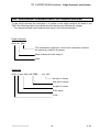
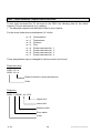
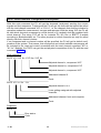
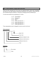
Contents
I)
V24/RS232/485 Interface – Basics
1
2
3
4
5
6
II)
1- 1
Introduction ................................................................................................ 1 - 1
Hardware ................................................................................................... 1 - 2
Protocol settings ........................................................................................ 1 - 3
3.1 Command telegram............................................................................. 1 - 3
3.2 Response telegram ............................................................................. 1 - 4
3.3 Command telegram for RS485 BUS operating ................................... 1 - 5
3.4 Response telegram for RS485 BUS operating.................................... 1 - 6
Specifications of data settings ................................................................... 1 - 7
4.1 Head telegram (Header)...................................................................... 1 - 7
4.2 Data block and error status byte ......................................................... 1 - 8
4.3 End of telegram................................................................................... 1 - 9
Examples for potential responses to control or write commands resp.
to command telegrams with data (format) errors ....................................... 1 -10
Function sequence and error status after the receipt of the
"SRES" or "STBY" commands ................................................................... 1 -18
V24/RS232/485 Interface – Single Analyzers and Systems
1
2
3
4
5
2- 1
Basic Informations ..................................................................................... 2 - 2
List of all Codes [Commands - Overview including page numbers] ..... 2 - 5
2.1 Control commands .............................................................................. 2 - 5
2.2 Read commands ................................................................................. 2 - 6
2.3 Write commands ................................................................................. 2 - 7
Description of all Control Commands ........................................................ 2 - 8
Description of all Read Commands ........................................................... 2 -39
Description of all Write Commands............................................................ 2 -85
Supplement
1
2
Overview about working AK commands in NGA devices ......... Supplement - 1
AK Service Commands............................................................. Supplement - 3
90003752(1) [AK-Commands] 10/98
AK
AK
90003752(1) [AK-Commands] 10/98
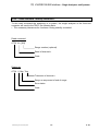
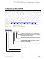
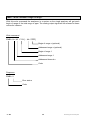
I) V24/RS232/485-Interface - Basics
Protocol settings of a serial interface
between a test bench control computer
and peripheral analyzers on exhaust test benches
1. Introduction
The serial interface is made for slow point to point connections (f ≤ 10 Hz). The
communication between the test bench control computer (TBCC) and the peripheral
analyzers works according to the master slave principle. That means that the peripheral
analyzers will only answer with a response telegram to the command telegram of the
TBCC. They will not send an own message.
You can distinguish two cases:
(1) Analyzers in a function unit (system)
Some analyzers are combined to a logical unit. They are connected to
an front-end computer. In that case the communication will not take
between the TBCC and the analyzers, but between the TBCC and
computer. Each analyzer or the whole system unit will be identified
channel number:
K0 is the channel number for the whole defined system.
("Assembling command resp. assembling report")
Kn (n=1, nmax) is the channel number for each analyzer.
KV is the channel number for the front-end computer.
the TBCC via
place directly
the front-end
by a defined
(2) Single analyzers
Each analyzer is connected directly to the TBCC. In that case the identification of each
analyzer will be done by the hardware connections and not by a software control. That
is why the two channel number bytes (Kn) could be deleted. But in spite of that the
channel number is generally 0 (K0) to get a uniform protocol.
The data transfer will only be done by ASCII code to get an easy handling of the protocol
with a terminal for simulation of the TBCC, the system unit and the analyzers. Therefore,
no parity check will be done as data saving.
90003752(1) [AK-Commands] 10/98
AK
1-1
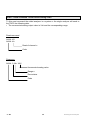
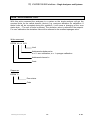
2. Hardware
1. Baud rate:
1200, 2400, 4800, 9600, 19200
2. Length of signs:
1 start bit
7 or 8 data bits
1 or 2 stop bits
3. Parity:
even/odd/none
4. Operating:
full duplex, no echo
5. Handshake:
Xon/Xoff
6. Plug:
9 pin sub d, socket
7. Pin assignment:
RS 232 module
GND
Relay 1 contact NC/NO
Rxd
Relay 2 contact NC/NO
TxD
Relay 3 contact NC/NO
NC
Relay common node
GND
RS 485 module
GND
Relay 1 contact NC/NO
RxD-
Relay 2 contact NC/NO
RxD+
Relay 3 contact NC/NO
TxD+
Relay common node
TxD-
1-2
AK
90003752(1) [AK-Commands] 10/98
I) V24/RS232/485-Interface - Basics
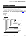
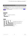
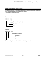
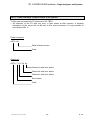
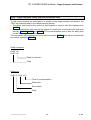
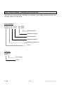
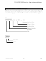
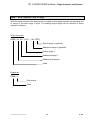
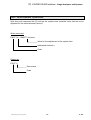
3. Protocol settings
The data and command transfer protocol has the following structure:
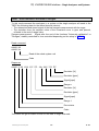
3.1. Command telegram
1. Byte
STX
2. Byte
DON'T CARE
3. Byte
FUNCT. CODE 1
4. Byte
FUNCT. CODE 2
5. Byte
FUNCT. CODE 3
6. Byte
FUNCT. CODE 4
7. Byte
BLANK
8. Byte
"K"
VARIABLE DATA
9. Byte
NUMBER
(number with several
digits possible)
D
A
T
A
n. Byte
HEAD
(other data
can also disappear,
depending on the
function code)
ETX
90003752(1) [AK-Commands] 10/98
END
AK
1-3
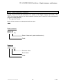
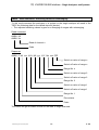
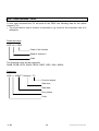
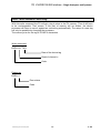
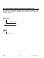
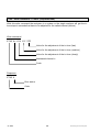
3.2. Response telegram
1. Byte
STX
2. Byte
DON'T CARE
3. Byte
FUNCT. CODE 1
4. Byte
FUNCT. CODE 2
5. Byte
FUNCT. CODE 3
6. Byte
FUNCT. CODE 4
7. Byte
BLANK
8. Byte
ERROR STATUS
D
A
T
A
n. Byte
1-4
HEAD
FIXED
DATA
VARIABLE DATA
(can also disappear,
depending on the
function code)
ETX
END
AK
90003752(1) [AK-Commands] 10/98
I) V24/RS232/485-Interface - Basics
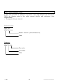
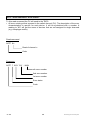
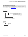
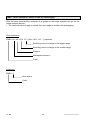
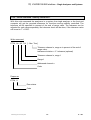
3.3. Command telegram for RS485 BUS operating
1. Byte
STX
2. Byte
BUS ADDRESS
3. Byte
FUNCT. CODE 1
4. Byte
FUNCT. CODE 2
5. Byte
FUNCT. CODE 3
6. Byte
FUNCT. CODE 4
7. Byte
BLANK
8. Byte
"K"
VARIABLE DATA
9. Byte
NUMBER
(Number with several
digits possible)
D
A
T
A
n. Byte
HEAD
(other data
can also disappear,
depending on the
function code)
ETX
90003752(1) [AK-Commands] 10/98
END
AK
1-5
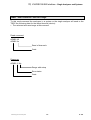
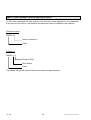
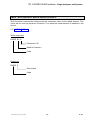
3.4. Response telegram for RS485 BUS operating
1. Byte
STX
2. Byte
BUS ADDRESS
3. Byte
FUNCT. CODE 1
4. Byte
FUNCT. CODE 2
5. Byte
FUNCT. CODE 3
6. Byte
FUNCT. CODE 4
7. Byte
BLANK
8. Byte
ERROR STATUS
D
A
T
A
n. Byte
1-6
HEAD
FIXED
DATA
VARIABLE DATA
(can also disappear,
depending on the
function code)
ETX
END
AK
90003752(1) [AK-Commands] 10/98
I) V24/RS232/485-Interface - Basics
4. Specifications of data settings
4.1. Head telegram (Header)
The begin of each transfer is a "STX" in the first byte. Each "STX" will start a new transfer.
Previous transfers will be deleted, if they are not finished by "ETX". That means, only
completed telegrams may be interpreted and answered.
You can take any content for the "DON'T CARE" byte, excluding control signs or signs
reserved by the AK commands.
For the RS485 BUS operating an address byte will be used instead of the "DON'T CARE"
byte. The analyzers will only answer to this command if the bus address setup will concur
with this byte.
In the command telegram a function code will be sent to the system unit or the analyzer
with the four function bytes.
In the response telegram this function code will be sent back as an echo if the transfer is
successful. The echo will be four question marks (????), if
• the command telegram has not minimum the number of bytes of the head telegram, the
channel number in the data part and the end telegram (number of bytes = 10; using a
channel number with two digits = 11 bytes) or
• the function code has errors or is unknown.
The function code may not contain blanks.
There are three groups of function codes:
(1) Control commands
(2) Read commands
(3) Write commands
90003752(1) [AK-Commands] 10/98
AK
1-7
4.2. Data block and error status byte
The data presentation is variable. A fixed format will not be used. A blank or a <CR> with
<LF> will be used as separating characters of data. The separation with <CR><LF> will
only be done, if the following complete date will have more than 60 digits. Each data set
will begin normally with a blank.
The data block of the command telegram has only variable data. These data depend on
the function code. They can disappear for some function codes excluding the channel
number. The channel number can have more than two bytes.
The data block of the response telegram is divided in fixed and variable data. The first
digit of the fixed data is a blank followed by an error status byte. The error status number
will be zero for an error free running analyzer or system unit. The error status number will
be counted up from 1 to 9 with each change in the error status. The error status number
will be zero again after the errors will be removed. Changing the status of the system will
not change the error status number. The variable data depend on the function code. They
can disappear for some function codes.
The long and variable floating point format or the E- Format are allowed to display the
digits of numbers. You can find in each analyzer protocol which of these formats may be
used. The decimal point can disappear for integers. The "+/-" sign may only be used for
negative numbers. Digits without physical meaning have to be vanished.
You can distinguish the following cases if a date with an error exists for a reading:
(1) The transfer of the date is not possible, e.g. an analyzer in a system is missing or it
cannot send a signal.
→ The date will be replaced by a "#".
(2) The date is only valid with restrictions, e.g. FID temperature too low.
→ The date will begin with a "#".
Range overflow and range underflow will be displayed in the same way. "Valid" means
that no criterions of plausibility will be considered.
Example:
You ask for a concentration value and the analyzer is in the "stand-by" mode. The date
must not be marked with "#" as "valid with restrictions", if the analyzer would work
normally in the operation mode.
1-8
AK
90003752(1) [AK-Commands] 10/98
I) V24/RS232/485-Interface - Basics
If an analyzer or a system is not in the "REMOTE" status, the control and write commands
have to report "OF" ("Offline") in the data set to the. In system units the channel number
has to be reported, too.
If one analyzer is missing, a system unit has to send the channel number and "NA" ("Not
Available") to the test bench control computer with control and write commands.
A response telegram is not possible, if the test bench control computer has a direct
contact to the analyzers and one analyzer is missing or the whole system is missing. So
the test bench control computer has to realize the missing of devices by "Time Out".
If the system or the analyzer is occupied by executing a function, the new start of a control
command will lead to the response "BS" (Busy) in the data block of the response
telegram. The running function will not be disturbed. Exception: The order was a software
reset.
If the data or parameters transfer is not complete (i.e. not expected format) in the
command telegram to the system or the analyzer, the test bench control computer will get
a "SE" (Syntax Error) in the data block of the following response telegram.
If the system or the analyzers cannot work with the data or the parameters of the
command telegram (data error, parameter error), the test bench control computer will get
a "DF" (data error) in the data block of the following response telegram.
4.3. End of telegram
Each transfer will end with "ETX" in the last byte.
90003752(1) [AK-Commands] 10/98
AK
1-9
5. Examples for potential responses to control or write commands resp.
to command telegrams with data (format) errors:
1. Analyzer and/or system unit with several analyzers "Online"
and called analyzers are existing.
1. Byte
STX
2. Byte
DON'T
CARE
3. Byte
C
4. Byte
O
5. Byte
D
6. Byte
E
7. Byte
BLANK
8. Byte
x
Error status byte
evtl.
variable
...
.
...
Data
n. Byte
ETX
Error status byte:
1 - 10
Value is zero:
Value is not zero:
Device without error.
Device with one or more errors.
AK
90003752(1) [AK-Commands] 10/98
I) V24/RS232/485-Interface - Basics
2. Analyzer and/or system unit with several analyzers "Offline"
and called analyzers are existing.
1. Byte
STX
2. Byte
DON'T
CARE
3. Byte
C
4. Byte
O
5. Byte
D
6. Byte
E
7. Byte
BLANK
8. Byte
x
9. Byte
BLANK
10. Byte
K
11. Byte
n
12. Byte
BLANK
13. Byte
O
14. Byte
F
Error status byte
evtl.
variable
...
.
...
Data
n. Byte
ETX
Error status byte:
11. Byte:
90003752(1) [AK-Commands] 10/98
Value is zero:
Device without error.
Value is not zero: Device with one or more errors.
Channel number is zero: "The whole system unit offline".
Channel number is one to n: "Single analyzer offline".
AK
1 - 11
3. Called system unit "online", called single analyzer not available.
If the test bench control computer will call the devices directly and the system unit or
the analyzer are not available, you will not get any response telegram. So, the test
bench control computer will have to realize the missing of the system or of the analyzer
by "Time Out".
1. Byte
STX
2. Byte
DON'T
CARE
3. Byte
C
4. Byte
O
5. Byte
D
6. Byte
E
7. Byte
BLANK
8. Byte
x
9. Byte
BLANK
10. Byte
K
11. Byte
n
12. Byte
BLANK
13. Byte
N
14. Byte
A
15. Byte
ETX
Error status byte
Error status byte:
Value is zero:
Value is not zero:
11. Byte:
Channel number one to n: "Called device not available".
1 - 12
Device without error
Device with one or more errors
AK
90003752(1) [AK-Commands] 10/98
I) V24/RS232/485-Interface - Basics
4. Called system unit "offline", called single analyzer not available.
If the test bench control computer will call the devices directly and the system unit or
the analyzer are not available, you will not get any response telegram. So, the test
bench control computer will have to realize the missing of the system or of the analyzer
by "Time Out".
1. Byte
STX
2. Byte
DON'T
CARE
3. Byte
C
4. Byte
O
5. Byte
D
6. Byte
E
7. Byte
BLANK
8. Byte
x
9. Byte
BLANK
10. Byte
K
11. Byte
0
12. Byte
BLANK
13. Byte
O
14. Byte
F
15. Byte
BLANK
16. Byte
K
17. Byte
n
18. Byte
BLANK
19. Byte
N
20. Byte
A
21. Byte
ETX
90003752(1) [AK-Commands] 10/98
Error status byte
AK
1 - 13
Error status byte:
Value is zero:
Value is not zero:
11. Byte:
Channel number zero: "System unit offline"
17. Byte:
Channel number one to n: "Called device not available.
1 - 14
Device without error.
Device with one or more errors.
AK
90003752(1) [AK-Commands] 10/98
I) V24/RS232/485-Interface - Basics
5. Called unit or channel is busy with a running function.
1. Byte
STX
2. Byte
DON'T
CARE
3. Byte
C
4. Byte
O
5. Byte
D
6. Byte
E
7. Byte
BLANK
8. Byte
x
9. Byte
BLANK
10. Byte
K
11. Byte
n
12. Byte
BLANK
13. Byte
B
14. Byte
S
15. Byte
ETX
Error status byte
Error status byte:
Value is zero:
Value is not zero:
11. Byte:
Channel number is zero: "The whole unit is busy".
Channel number is one to n: "Single analyzer is busy".
90003752(1) [AK-Commands] 10/98
Device without error.
Device with one or more errors.
AK
1 - 15
6. The data are incomplete or the data do not have the expected format.
1. Byte
STX
2. Byte
DON'T
CARE
3. Byte
C
4. Byte
O
5. Byte
D
6. Byte
E
7. Byte
BLANK
8. Byte
x
9. Byte
BLANK
10. Byte
K
11. Byte
n
12. Byte
BLANK
13. Byte
S
14. Byte
E
15. Byte
ETX
Error status byte:
1 - 16
Error status byte
Value is zero:
Value is not zero:
Device without error.
Device with one or more errors.
AK
90003752(1) [AK-Commands] 10/98
I) V24/RS232/485-Interface - Basics
7. The data or the parameters do not have the expected size.
1. Byte
STX
2. Byte
DON'T
CARE
3. Byte
C
4. Byte
O
5. Byte
D
6. Byte
E
7. Byte
BLANK
8. Byte
x
9. Byte
BLANK
10. Byte
K
11. Byte
n
12. Byte
BLANK
13. Byte
D
14. Byte
F
15. Byte
ETX
Error status byte:
90003752(1) [AK-Commands] 10/98
Error status byte
Value is zero:
Value is not zero:
Device without error.
Device with one or more errors.
AK
1 - 17
6. Function sequence and error status after the receipt of the
'SRES' or 'STBY' commands
1. The test bench control computer is sending the control command SRES (Reset)
to the system unit or any single analyzer.
All running functions or procedures will be canceled. An initializing will start, that is
analogous to the switching on of the system unit or the analyzer: CPU and memory
check, regulating or controlling of required temperatures, igniting of the flame in a FID
an so on. The operation mode of the system or analyzer is "stand-by" during the
initializing, even if the device is not ready and error free. That means, the status STBY
will be reported to the read command ASTZ. The test bench control computer can only
realize with the read command ASTF (error status), if the device is ready for
measurements. The device will be ready to measure, if the essential functions of the
current measuring instruction will be error free.
Example:
The status of the system unit or analyzer is SXYZ. The test bench control computer
sends SRES:
Test bench control computer sends SRES Kn
→ System or analyzer will response SRES x
The system unit or the analyzer will cancel the status SXYZ. It will run a CPU and
memory check and it will control the temperatures. If the temperatures are out of the
allowed setpoint range, the device will regulate it. The FID will control the flame and will
try to ignite it, if necessary, and so on. The test bench control computer will read the
operation mode and the error status:
Test bench control computer sends ASTZ Kn
→ System or analyzer will response ASTZ 0 SMAN STBY
or
Test bench control computer sends ASTZ Kn
System or analyzer will response ASTZ x SMAN STBY
Test bench control computer sends ASTF Kn
System or analyzer will response ASTF x n
The error status byte will be zero and the system or the analyzer will be ready to
measure, if all temperatures are in the allowed setpoint range, if the FID flame is
burning etc.
If these parameters are not correct, the error status byte will be different from zero. The
test bench control computer will read the operation mode and the error status as long
as the system or the analyzer will be ready to measure. The test bench control
computer will control the maximum time for this reading.
1 - 18
AK
90003752(1) [AK-Commands] 10/98
I) V24/RS232/485-Interface - Basics
2. The test bench control computer is sending the control command STBY (Standby) to the system unit or any single analyzer.
There are two different cases:
A If the system or the analyzer is resting, this mode will be finished. Then, it will be tried to
get the stand-by mode ready for an error free measurement. The system or the
analyzer will regulate all temperatures to the required setpoints, that were down during
the resting. The FID will control the flame burning and if necessary it will try to ignite the
flame etc. The operation mode of the system or analyzer is "stand-by" during these
checkups, even if the device is not ready and error free. That means, the status STBY
will be reported to the read command ASTZ. The test bench control computer can only
realize with the read command ASTF (error status), if the device is ready for
measurements. The device will be ready to measure, if the essential functions of the
current measuring instruction will be error free.
Example:
The system or the analyzer is resting. No error is existing. The test bench control
computer will ask for the operation mode:
Test bench control computer sends ASTZ Kn
→ System or analyzer will response ASTZ 0 SREM SPAU
Test bench control computer sends STBY. System or analyzer shall accept the standby mode:
Test bench control computer sends STBY Kn
→ System or analyzer will response STBY 0
The system or analyzer is finishing the resting. Then, it will try to get the stand-by mode
for an error free measurement. The system or analyzer will check the conditions: Are all
temperatures in the setpoint range ? Is the FID flame burning ? etc. The test bench
control computer will read the operation mode:
Status is error free:
Test bench control computer sends ASTZ Kn
→ System or analyzer will response ASTZ 0 SREM STBY
or status has still some errors:
Test bench control computer sends ASTZ Kn
→ System or analyzer will response ASTZ x SREM STBY
Test bench control computer sends ASTF Kn
→ System or analyzer will response ASTF x n
The error status byte will be zero and the system or the analyzer will be ready to
measure, if all temperatures are in the allowed setpoint range, if the FID flame is
burning etc.
If these parameters are not correct, the error status byte will be different from zero. The
test bench control computer will read the operation mode and the error status as long
as the system or the analyzer will be ready to measure. The test bench control
computer will control the maximum time for this reading.
90003752(1) [AK-Commands] 10/98
AK
1 - 19
B The system or the analyzer is in the operation mode SXYZ. This mode will be finished.
Then, it will be tried to get the stand-by mode ready for an error free measurement. If
there will be an error in the function SXYZ, the system or the analyzer will try to remove
this error to get the stand-by mode ready for an error free measurement (i.e. FID flame
is not burning, the FID will try to ignite). The operation mode of the system or analyzer
is "stand-by" during these check-ups, even if the device is not ready and error free.
That means, the status STBY will be reported to the read command ASTZ. The test
bench control computer can only realize with the read command ASTF (error status), if
the device is ready for measurements. The device will be ready to measure, if the
essential functions of the current measuring instruction will be error free.
Example:
The system or the analyzer is in the operation mode SXYZ. An error is existing with the
error number n, i.e. FID flame is not burning. The test bench control computer will ask
for the error status:
Test bench control computer sends ASTF Kn
→ System or analyzer will response ASTF x n
Test bench control computer sends STBY. System or analyzer shall accept the standby mode and get ready for an error free measurement:
Test bench control computer sends STBY Kn
→ System or analyzer will response STBY x
The system or analyzer is finishing the operation mode SXYZ. Then, it will try to get the
stand-by mode for an error free measurement. The system or analyzer will check the
conditions and will try to remove the error, i.e. ignition of the FID flame. The test bench
control computer will read the operation mode:
Error is removed (e.g. Flame was ignited):
Test bench control computer sends ASTZ Kn
→ System or analyzer will response ASTZ 0 SREM STBY
or
Error is still existing (e.g. Flame has not been ignited):
Test bench control computer sends ASTZ Kn
→ System or analyzer will response ASTZ x SREM STBY
Test bench control computer sends ASTF Kn
→ System or analyzer will response ASTF x n
The error status byte will be zero and the system or the analyzer will be ready to
measure, if the error is removed i.e. the FID flame is still burning.
If these parameters are not correct, the error status byte will be different from zero. The
test bench control computer will read the operation mode and the error status as long
as the system or the analyzer will be ready to measure. The test bench control
computer will control the maximum time for this reading.
1 - 20
AK
90003752(1) [AK-Commands] 10/98
II) V24/RS232/485 Interface - Single Analyzers and Systems
Specifications of the criterions and codes for the communication
between
• the front-end computer (system computer) of an exhaust analyzer system and the test
•
•
•
•
•
bench control computer.
each analyzer of an exhaust analyzer system and the test bench control computer.
the front-end computer (system computer) of an exhaust analyzer system and their
single devices. The following measurement systems and equipments can also be such
single devices.
the front-end computer (system computer) of a fuel consumption analyzer and a test
bench control computer.
the front-end computer (system computer) of an SHED measurement equipment and
the test bench control computer. (SHED: Sealed Housing for Evaporative Determination)
the front-end computer (system computer) of a sampling system and the test bench
control computer.
The computer of an analyzer or of a system will be named as FU
(Function Unit) and the test bench control computer will be abbreviated
with TBCC.
90003752(1) [AK-Commands] 10/98
AK
2-1
1. Basic Informations
You can distinguish three cases:
(1) Exhaust analyzer system:
Some analyzers are combined logically. That means, these analyzers are connected with
the TBCC via an front-end computer (system computer). The communication does not
take place directly between the TBCC and the analyzers, but it will take place via the frontend computer. The identification of each device resp. of the whole system will be done by
a channel number. K0 means the whole configured analyzer system ("assembling
command resp. assembling report"). Kn (n=1, nmax) means each physical available
analyzer. KV means the corresponding front-end computer.
Some analyzers and the sampling devices or systems (e.g. CVS equipment, particle
sampler, sampling system, etc.) are combined logically. That means, these analyzers are
connected with the TBCC via an front-end computer (system computer). The communication does not take place directly between the TBCC and the devices or systems, but it
will take place via the front-end computer. The identification of each device and system
will be done by a channel number. The handling of the analyzers will be like described
above. All the other devices or systems can only be called directly by the corresponding
channel number. The front-end computer must know the mnemonics of these devices and
systems. Furthermore, the front-end computer has to be able to send orders and read
commands to the channels resp. to send responses to the TBCC.
(2) Single exhaust analyzers (single channel analyzers):
All analyzers are connected to the TBCC individually. So, an identification of the analyzers
by the software would not be necessary, because the analyzers are identified by their
hardware connections. But to get a homogeneous protocol, the channel number will be
indicated with K0.
(3) Single exhaust analyzers (multi channel analyzers):
All analyzers are connected to the TBCC individually, but they measure more than a single
component (e.g. CO and C02). The identification by the software is necessary, because it
will call the single channels resp. components. That is why such a single analyzer will be
treated like a system.
2-2
AK
90003752(1) [AK-Commands] 10/98
II) V24/RS232/485 Interface - Single Analyzers and Systems
The codes determined in this manual are valid for the communication between
• the TBCC and the front-end computer of an exhaust analyzer system.
• the front-end computer of an exhaust analyzer system and the corresponding single
devices.
• the TBCC and the single exhaust analyzers connected directly to the TBCC.
• the TBCC and other exhaust measuring or analyzing devices or equipments connected
directly to the TBCC.
The floating point format is valid for the signal transfer.
The physical units are determined as follows:
• Exhaust values: ppm
• Temperatures:
• Pressures:
• Flow:
K
Pa
l/min
The analyzer system or each analyzer can be set to the operation mode "MANUAL"
selecting "REMOTE DISABLE" for the parameter "REMOTE EN-/DISABLE". This setup
does not depend on the previous status of the system or analyzer.
If you select "REMOTE ENABLE", the mode "MANUAL" will retain for the moment, but the
TBCC can call this operation mode with a control command. If the TBCC will setup the
system/the analyzer to "REMOTE", the system/the analyzer will execute control
commands from the TBCC. Precondition: The system/the analyzer is able to start the
function selected.
In the mode "REMOTE DISABLE", the TBCC can only send read commands. It is only
possible to read signals and status informations. If then the system or the analyzer is in
the mode "MANUAL", it will ignore the control command from the TBCC. No change of the
error status will be done in the response to the TBCC. Instead of that the response will
display "MANUAL" as first date.
The same will be valid, if the parameter is "REMOTE ENABLE", but the TBCC did switch
the system/the analyzer to the mode "MANUAL".
Otherwise, the operation mode can only be recognized by reading the status.
This is also valid during a test is running.
90003752(1) [AK-Commands] 10/98
AK
2-3
If it is possible in a system to put single channels together to lines, so the following
definition will be valid:
A line is the summary of "1-x" analyzers to a logical group "y", that can be switched
physically to a gas channel "z". Each device can only be assigned to one line at the
same time. If you will try to assign a channel to another line and this channel is already
assigned, the front-end computer will send as response "DF" (data error).
The organization of each defined line will be done in the front-end computer (CODE
KV Ln ...). The order must be sent to the front-end computer "KV".
A line will be dissolved by the configuration without assignment of channels (CODE KV
Ln) or by the reset order (SRES).
All available gas inputs can be assigned to a defined line. So it is possible to assign
different lines to different gas sampling points, e.g. in front of a catalyst, behind a
catalyst. If the gas running time will change in such cases, you have to regard for it.
2-4
AK
90003752(1) [AK-Commands] 10/98
II) V24/RS232/485 Interface - Single Analyzers and Systems
2. List of all Codes
2.1. Control commands
CODE
SALI
SARA
SARE
SATK
Kn
Kn
Kn
Kn
SEGA
SEMB
SFRZ
SGTS
SHDA
SHDE
SINT
SLCH
SLIN
Kn
Kn
Kn
Kn
K0
K0
Kn
Kn
Kn
SLST
SMAN
SMGA
SNAB
SNGA
SPAB
SPAU
Kn
Kn
Kn
Kn
Kn
Kn
Kn
SQEF
SREM
SRES
SROF
Kn
Kn
Kn
Kn
SRON
SSPL
ST9O
STBY
Kn
Kn
Kn
Kn
Mm
Mm
Mm
Mm
Mm
Function
Page
Linearization check with spangas
Autoranging "OFF" (located range will remain)
Autoranging "ON"
Autom. calibration
(zero and span calibration + zerogas + stand-by)
Spangas (spangas will flow with time limit)
Set range (1, 2, 3, 4)
Decimal point setup for floating point format
Device test
Hold mode "OFF"
Hold mode "ON"
Start integration (integral average)
Linearization check (with gas distribution)
Linearization
(with determination of corrections and saving)
Set linearization step and get values
Operation mode "Manual"
Samplegas (will be sucked or will be on)
Zerogas calibration
Zerogas (zerogas will flow with time limit)
Spangas calibration
Pause (resting status, e.g. pumps, ozonator, deozonator, high
voltage off, gas input closed within the device)
Cross interference (only for CO analyzers)
Operation mode "Remote"
Reset (analyzer will change via initializing mode to stand-by)
Delay modus "OFF" (operation mode: signal output with/without
delay time, involved are SINT, AKON, AIKO, AIKG, analog signal)
Delay modus "ON" (analog to "SROF")
Purging (purge air will be sucked or will be on)
Set t90 time step (S = fast, M = medium, L = slowly)
Stand-by (get ready for measurement no matter of the previous
history)
2-8
2-9
2-9
2 - 10
2 - 15
2 - 16
2 - 18
2 - 19
2 - 20
2 - 20
2 - 21
2 - 22
2 - 23
2 - 24
2 - 25
2 - 26
2 - 27
2 - 28
2 - 29
2 - 30
2 - 31
2 - 32
2 - 33
2 - 34
2 - 34
2 - 35
2 - 36
2 - 37
Optional:
SCAL
SENO
SNOX
Kn
Kn
Kn
Kn:
Mm:
Channel n
Range m
Start system calibration (only for platform)
NO measurement (operation mode CLD)
NOx measurement (operation mode CLD)
2 - 13
2 - 17
2 - 17
Response
The response to the control commands will contain the CODE of the control command and
the error status byte (0-9).
90003752(1) [AK-Commands] 10/98
AK
2-5
2.2. Read commands
CODE
AAEG
AALI
AANG
AEMB
AFDA
AFDA
AGID
AGRW
AIKG
AIKO
AKAK
AKAL
AKFG
AKON
ALCH
ALIK
ALIN
ALKO
ALST
AM90
AMBA
AMBE
AMBU
AMDR
AQEF
ASOL
ASTA
ASTF
ASTZ
ASYZ
AT9O
ATEM
ATOL
AVEZ
AZEI
Function
Kn
Kn
Kn
Kn
Kn
Kn
Kn
Kn
Kn
Kn
Kn
Kn
Kn
Kn
Kn
Kn
Kn
Kn
Kn
Kn
Kn
Kn
Kn
Kn
Kn
Kn
Kn
Kn
Kn
Kn
Kn
Kn
Kn
Kn
Kn
Page
Spangas deviation
Deviations of the last linearization checks with spangas
Zerogas deviation
Selected range (R1, R2, R3, R4)
CODE Zero- /spangas time (function length of calibration)
CODE Purge time
Device identification
m
Limit
Concentration integral average; all (in ppm)
Concentration integral average (in ppm)
Mm
Calibration gas concentration (in ppm)
Stored calibration corrections
Configuration of the system
Concentration (current value in ppm)
Mm
Deviations of the last linearization checks
Calculation of linearization curve
Mm
Linearization values in the device (X/Y = Setpoint-/raw value)
Mm
Polynomial coefficents of the linearization curve
Linearization steps
Actual response time (t90 time)
Mm
Begin of range (in ppm)
Mm
End of range (in ppm)
Switch levels for autoranging
Manual adjusted pressure
Cross interference check result (in ppm) (only for CO analyzers)
Setpoint value with limits
General status of the system
Internal error status
Device status
System time (year, month, day, hour, min., sec.)
T90 time (response time)
m
Temperature
Mm
Stability tolerances
Delay and synchronization time
CODE Times (for procedures)
Mm
2 - 39
2 - 40
2 - 41
2 - 45
2 - 46
2 - 46
2 - 47
2 - 48
2 - 49
2 - 51
2 - 53
2 - 54
2 - 57
2 - 58
2 - 61
2 - 62
2 - 63
2 - 64
2 - 65
2 - 66
2 - 67
2 - 68
2 - 69
2 - 70
2 - 71
2 - 72
2 - 73
2 - 74
2 - 76
2 - 78
2 - 79
2 - 80
2 - 81
2 - 83
2 - 84
Optional:
ABST
ADRU
ADUF
AKEN
AKOW
AUKA
Kn:
Mm:
Kn
Kn m
Kn m
Kn
Kn Mm
Kn
Channel n
Range m
Counter of operating hours
Pressure (for service)
Flow (for service)
Device tag
Correction (zerogas calibration and gradient)
Uncorrected analog value
2 - 42
2 - 43
2 - 44
2 - 56
2 - 60
2 - 82
Response
The response to the read command will contain the CODE of the read command,
the error status byte (0-9) and the data.
2-6
AK
90003752(1) [AK-Commands] 10/98
II) V24/RS232/485 Interface - Single Analyzers and Systems
2.3. Write commands
CODE
EFDA
Kn
EFDA
EGRW
EKAK
Kn
Kn
Kn
EKFG
ELIN
Kn
Kn
ELKO
ELST
EMBA
Kn
Kn
Kn
EMBE
Kn
EMBU
EMDR
ESOL
ESYZ
ET9O
ETOL
Kn
Kn
Kn
Kn
Kn
Kn
EVEZ
EZEI
Kn
Kn
Function
Page
CODE
DATA
CODE
DATA
Mm
DATA
DATA
Mm
DATA
DATA
DATA
Mm
DATA
Mm
DATA
DATA
DATA
m DATA
DATA
DATA
Mm
DATA
DATA
CODE
DATA
Zero- /spangas time (function length of calibration)
2 - 85
Purge time
Limits
Calibration gas concentration (in ppm)
Value = 0: no spangas available
Configuration of the system
Linearization values in the device (X/Y = Setpoint-/raw value)
2 - 85
2 - 87
2 - 88
Polynomial coefficents of the linearization curve
Linearization steps
Begin of range (in ppm)
Value = 0: no range defined
End of range (in ppm)
Value = 0: no range defined
Switch levels for autoranging
Manual adjusted pressure
Setpoint value with limits
System time (year, month, day, hour, min., sec.)
T90 time (response time)
Stability tolerances
2 - 92
2 - 93
2 - 94
2 - 96
2 - 97
2 - 98
2 - 99
2 -100
2 -101
Delay and synchronization time
Times (for procedures)
2 -102
2 -103
DATA
Device tag
2 - 89
2 - 90
2 - 91
2 - 95
Optional:
EKEN
Kn
Kn:
Mm:
Channel n
Range m
Response
The response to the write commands will contain the CODE of the write command and
the error status byte (0 - 9).
90003752(1) [AK-Commands] 10/98
AK
2-7
3. Description of all Control Commands
SALI – Control command "Linearization check with spangas"
Starting this command the analyzer in a system or the single analyzer will start the
spangas flow with all available spangases one after another. It will check the setpoint
values automatically. The device will record the determined values and store the raw/
setpoint deviations. These deviations can be read with the command "AALI".
Control command
SALI Kn Mx
Function associated to channel n, range x
Code
Response
SALI 0
Error status
Code
2-8
AK
90003752(1) [AK-Commands] 10/98
II) V24/RS232/485 Interface - Single Analyzers and Systems
SARA – Control command "Autoranging OFF"
SARE – Control command "Autoranging ON"
Starting the command "Autoranging ON" the analyzers in a system or the single analyzer
will select the best range for the current concentration automatically.
With the control command "SEMB" the autoranging will be stopped and the range sent
with the "SEMB" command will be selected. The command "Autoranging OFF" will stop
this function, but the found range will remain.
Control command
SARE K0
SARA K0
Function associated to the whole system unit
Code
SARE Kn
SARA Kn
Function associated to a single analyzer
Code
90003752(1) [AK-Commands] 10/98
AK
2-9
SATK – Control command "Automatic calibration"
Starting this command the analyzers in a system or the single analyzer will start a
calibration procedure to determine the correction values. The required calibration gases
and the pumps will be switched on automatically. Then, the calibration procedure will start
automatically. Such a procedure has to run until the end. It may not be canceled or
interrupted by other functions. Otherwise it is not sure that the correction values will be
valid to calculate the exhaust values of analysis. Exceptions are the commands "Reset" or
"Stand-by". After the procedure will be over the system, the analyzers in a system or the
single analyzer will have to change to the operation mode "Stand-by".
Control command
SATK K0
Function associated to the whole system unit
Code
SATK K1 Kn
Function associated to channel n
Function associated to channel 1
Code
SATK Kn M3
Function associated to channel n and range 3
Code
Response
SATK 0
Error status
Code
2 - 10
AK
90003752(1) [AK-Commands] 10/98
II) V24/RS232/485 Interface - Single Analyzers and Systems
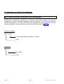
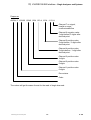
Stability control procedure
Parameters:
Wait dead time Tt, if
gases were switched
To
Tt
Start timer for time-out To
Time-out [xx s] (max. time for stability control)
Dead time [xx s]
(Wait after gas switching)
Ti
Integration time [xx,x s] (for K1, Knew)
Ts Stability time [xx s]
Tol. Tolerance [x,x % range]
Calculate concentration
mean value K1 over time Ti
Set and start timer
for stability time
Calculate concentration
mean value Knew over time Ti
Deviation = | K1 - Knew|
Time out ?
Yes
Signal not
stable
No
Dev. ≥ Tol.
Yes
K1 = Knew
No
No
Stability
time
over ?
Yes
Signal stable
Signal = Knew
90003752(1) [AK-Commands] 10/98
AK
2 - 11
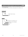
Stability control
Begin of
gas flow
Begin of
stability
control
New begin
of stability
control
Signal = Knew
Knew
Knew
K1
2 * Deviation
K1
Ti
Stability time Ts
Dead time Tt
Time-out
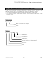
Stability controlled procedure of the zero/span calibration
Begin of the
function SATK
Average over Ti,
Read with AANG
Average over Ti,
Read with AAEG
Calibration
Ti
Ti
Calibration
Dead time
2 - 12
Stability
time
Stability
time
Dead time
AK
Stability
time
Stability
time
90003752(1) [AK-Commands] 10/98
II) V24/RS232/485 Interface - Single Analyzers and Systems
Only for platform: SCAL – Control command "Start system calibration"
To control the system calibration procedures the commands "SCAL", "STBY" and "ASTZ"
have to be used. With "SCAL" the procedures will be started. For more exact description
of procedures see also the "documentation of system calibration".
Starting condition: All attached analyzer module are in the stand-by mode ("AK STBY")
and the variable "CALSTAT" is "0".
Otherwise the response is "BUSY" (BS).
Control command
SCAL Kx m (n)
Optional parameters
Type of system calibration
Function associated to channel x
Code
m
0 = ZERO-CAL
1 = ZERO/SPAN-CAL
2 = PROGRAM
3 = TEST ZERO-GAS
4 = TEST SPAN-GAS1
5 = TEST SPAN-GAS2
6 = TEST SPAN-GAS3
7 = TEST SPAN-GAS4
8 = TEST CLOSE GASES
Kx
K0
K0
K0
K1...999
K1...999
K1...999
K1...999
K1...999
K1...999
n
n = 1: switch into test mode
else: switch into normal mode
time-out in sec
time-out in sec
time-out in sec
time-out in sec
time-out in sec
time-out in sec
If optional parameter "n" is not in the command string the appropriate variable will not be
changed.
90003752(1) [AK-Commands] 10/98
AK
2 - 13
Stop command
STBY K0
Function associated to the whole system unit
Code
Only using the channel number 0 (K0) will stop running "SYSCAL" procedure. Besides, all
procedures of the other analyzer modules will be stopped.
Response
SCAL 0
Error status
Code
Read command
ASTZ K0
Read of the whole FU
Code
With the command "ASTZ K0" it will be checked, if a system calibration is running or not.
"SCAL" will be sent back for a running system calibration. If no system calibration is
running this string will be missed.
2 - 14
AK
90003752(1) [AK-Commands] 10/98
II) V24/RS232/485 Interface - Single Analyzers and Systems
SEGA – Control command "Spangas"
Starting this command the analyzers in a system or the single analyzer will switch on the
calibration valve to spangas and switch on the required pumps. This function will only
check the end point. It will not correct the calibration. If continuous line recorders will be
available, the paper transport will also be switched on.
Control command
SEGA K0
Function associated to the whole system unit
Code
SEGA K1 Kn
Function associated to channel n
Function associated to channel 1
Code
Response
SEGA 0
Error status
Code
90003752(1) [AK-Commands] 10/98
AK
2 - 15
SEMB – Control command "Set range"
Starting this command the analyzers in a system or the single analyzer will set the range
that is named in the data. If the function "Autoranging" is running at that moment, it will be
stopped and the named range will be selected.
Control command
SEMB K1 M4 Kn M2
Function associated to channel n range 2
Function associated to channel 1 range 4
Code
Response
SEMB 0
Error status
Code
2 - 16
AK
90003752(1) [AK-Commands] 10/98
II) V24/RS232/485 Interface - Single Analyzers and Systems
Only for CLD module: SENO/SNOX – Control command "Operation mode CLD"
Starting the command "SENO" the CLD analyzers in a system or the single CLD analyzer
will start the NO measurement. The command "SNOX" will start the NOx measurement.
Control command
SENO Kn
Function associated to channel n
Code for NO measurement
SNOX Kn
Function associated to channel n
Code for NOx measurement
Response
SENO 0
Error status
Code for NO measurement
SNOX 0
Error status
Code for NOx measurement
90003752(1) [AK-Commands] 10/98
AK
2 - 17
SFRZ – Control command "Decimal point setup for floating point format"
With this command the number of digits for real numbers will be setup. The real numbers
will be set to the number of relevant digits.
Standard setup: 6 relevant digits
This command will have an effect to the output of all real numbers. It is not possible to
vary it for different channels.
Control command
SFRZ K0 n
n = 2, ..., 8: Number of relevant digits
n = 1:
Standard setup: 6 relevant digits
Function associated to the whole system unit
Code
Response
SFRZ 0
Error status
Code
2 - 18
AK
90003752(1) [AK-Commands] 10/98
II) V24/RS232/485 Interface - Single Analyzers and Systems
SGTS – Control command "Device test"
Starting this command the analyzers in a system or the single analyzer will switch off the
calibration gas and the samplegas. That means, all gas tubes to the analyzer device will
be closed and the pumps will be switched off. Then, the device can be checked via a gas
input that is located directly in front of the device.
Control command
SGTS K0
Function associated to the whole system unit
Code
SGTS K1 Kn
Function associated to channel n
Function associated to channel 1
Code
Response
SGTS 0
Error status
Code
90003752(1) [AK-Commands] 10/98
AK
2 - 19
SHDE – Control command "Hold status ON"
SHDA – Control command "Hold status OFF"
We have the possibility to activate the "Hold"-feature not only per calibration. We can do
this also by AK-Command "SHDE". With the command "SHDA" we have the possibility to
deactivate an activated "Hold" again. Starting the command "SHDE" will switch on the
"hold status". So it is possible to start the "Hold"-feature directly by AK command and not
only per calibration. With the "SHDA" command the "Hold status" will be deactivated.
Control command
SHDE K0
SHDA K0
Function associated to the whole system unit
Code
Response
SHDE 0
SHDA 0
Error status
Code
2 - 20
AK
90003752(1) [AK-Commands] 10/98
II) V24/RS232/485 Interface - Single Analyzers and Systems
SINT – Control command "Integrator"
Starting this command the FU will activate the internal integrators. The previous calculated
and stored integral averages will be set to zero. The integrator will calculate new integral
averages as long as the control command "SINT" will be received again. The result of the
integrator can be read with the command "AIKG".
Control command
SINT K0
Function associated to the whole system unit
Code
SINT K1 Kn
Function associated to channel n
Function associated to channel 1
Code
Response
SINT 0
Error status
Code
90003752(1) [AK-Commands] 10/98
AK
2 - 21
SLCH – Control command "Linearization check"
Starting this command the analyzers in a system or the single analyzer will switch on the
gas tubing to a gas distribution and a linearization procedure will run. The device will
record the correction values to the receiver specific raw curve. The deviations to the
correction values of the last determined linearization will be stored. Look at the command
"SLIN" for informations about the logic of the device control and of the gas distribution
control.
Control command
SLCH Kn Mn
Range n
Function associated to channel n
Code
Response
SLCH 0
Error status
Code
2 - 22
AK
90003752(1) [AK-Commands] 10/98
II) V24/RS232/485 Interface - Single Analyzers and Systems
SLIN – Control command "Linearization"
Starting this command the analyzers in a system or the single analyzer will switch on the
gas tubing to a gas distribution. A linearization procedure for the selected range will run.
The device will record the determined correction values to the receiver specific raw curve.
The values will be stored in the device to calculate the gas concentration. This procedure
will be controlled by several commands of the TBCC or the system. The device or the gas
distribution will only accept those commands, it they have already received the "SLIN"
command. The "SLIN" command prepares the device or the gas distribution to receive
and execute further commands being necessary for the linearization procedure. The
spangas concentration has to be set up before by the "EKAK" command.
Control command
SLIN Kn Mn
Range n
Function associated to channel n
Code
Response
SLIN 0
Error status
Code
90003752(1) [AK-Commands] 10/98
AK
2 - 23
SLST – Control command "Set linearization step"
Starting this command the gas distribution will switch on the named distribution step. The
device will work like described for the commands "SLIN" or "SLCH" depending on the
current procedure. The device will only accept the "SLST" command, if the commands
"SLIN" or "SLCH" were received before followed by the command "ELST".
Control command
SLST K1 n
Distribution step
Function associated to channel 1
Code
Response
SLST 0
Error status
Code
2 - 24
AK
90003752(1) [AK-Commands] 10/98
II) V24/RS232/485 Interface - Single Analyzers and Systems
SMAN – Control command "Operation mode MANUAL"
With this command the FU will change to the operation mode "Manual". Then it will only
be possible to start functions from an operating unit integrated in the FU. The same
operation mode will be enabled, if the service switch of the FU will be in the position
"Remote Disable". In that mode it will only be possible to answer to read commands of the
TBCC.
Control command
SMAN K0
Function associated to the whole system unit
Code
SMAN K1 Kn
Function associated to channel n
Function associated to channel 1
Code
Response
SMAN 0
Error status
Code
90003752(1) [AK-Commands] 10/98
AK
2 - 25
SMGA – Control command "Samplegas"
Starting this command the analyzers in a system or the single analyzer will switch on the
sample gas valve and the pumps necessary for the samplegas transport. If continuous line
recorders will be available, the paper transport will also be switched on.
Control command
SMGA K0
Function associated to the whole system unit
Code
SMGA K1 Kn
Function associated to channel n
Function associated to channel 1
Code
Response
SMGA 0
Error status
Code
2 - 26
AK
90003752(1) [AK-Commands] 10/98
II) V24/RS232/485 Interface - Single Analyzers and Systems
SNAB – Control command "Zerogas calibration"
Starting this command the analyzers in a system or the single analyzer will start a zerogas
calibration. The calibration gas flow will start automatically and the calibration procedure
will run. After this procedure will be over the system, the analyzer in a system or the single
analyzer will change to the stand-by mode. The running calibration procedure can be
canceled with the "STBY" command.
Control command
SNAB K0
Function associated to the whole system unit
Code
SNAB K1 Kn
Function associated to channel n
Function associated to channel 1
Code
Response
SNAB 0
Error status
Code
90003752(1) [AK-Commands] 10/98
AK
2 - 27
SNGA – Control command "Zerogas"
Starting this command the analyzers in a system or the single analyzer will switch on the
zerogas valve and the pumps necessary for the zerogas transport. This function will only
check the zero point. It will not correct the calibration. If continuous line recorders will be
available, the paper transport will also be switched on.
Control command
SNGA K0
Function associated to the whole system unit
Code
SNGA K1 Kn
Function associated to channel n
Function associated to channel 1
Code
Response
SNGA 0
Error status
Code
2 - 28
AK
90003752(1) [AK-Commands] 10/98
II) V24/RS232/485 Interface - Single Analyzers and Systems
SPAB – Control command "Spangas calibration"
Starting this command the analyzers in a system or the single analyzer will start a spangas
calibration. The calibration gas flow will start automatically and the calibration procedure
will run. After this procedure will be over the system, the analyzer in a system or the single
analyzer will change to the stand-by mode. The running calibration procedure can be
canceled with the "STBY" command.
Control command
SPAB K0
Function associated to the whole system unit
Code
SPAB K1 Kn
Function associated to channel n
Function associated to channel 1
Code
Response
SPAB 0
Error status
Code
90003752(1) [AK-Commands] 10/98
AK
2 - 29
SPAU – Control command "Pause"
With this command the FU will be set to a defined status of interruption. This command
will only be accepted, if the FU is already in the stand-by mode. The "SPAU" command
will switch off the operation modes (e.g. FID flame, pump of an NO device) or the
corresponding setpoints (e.g. temperature of the hot pipe). With the control command
„Reset“ or „Stand-by“ the FU will change to the stand-by mode to get ready for operation.
The real functionality of the "SPAU" command will depend on the used FU. It is part of
each device or system specification.
Control command
SPAU K0
Function associated to the whole system unit
Code
SPAU Kn
Function associated to channel n
Code
Response
SPAU 0
Error status
Code
2 - 30
AK
90003752(1) [AK-Commands] 10/98
II) V24/RS232/485 Interface - Single Analyzers and Systems
SQEF – Control command "Cross interference"
Starting this command the CO analyzer will measure wet C02. It will be produced by
streaming three percent C02 through water bottles at 20 degrees Celsius. The CO
analyzer will measure this gas mixture. The signal will be stored in the analyzer. It can be
read by the TBCC with the "AQEF" command. The measured concentration has to be
maximum 3 ppm for ranges smaller than 300 ppm. For bigger ranges it has to be
maximum 1 % of the end of range value. These limits will be controlled by the TBCC.
Control command
SQEF Kn
Function associated to channel n
Code
Response
SQEF 0
Error status
Code
90003752(1) [AK-Commands] 10/98
AK
2 - 31
SREM – Control command "Remote"
With this command the FU will change to the computing operation mode. Then, the
function start will only be possible by the TBCC. This operation mode may only be set, if
the service switch of the FU is in the position "Remote Enable".
Control command
SREM K0
Function associated to the whole system unit
Code
SREM K1 Kn
Function associated to channel n
Function associated to channel 1
Code
Response
SREM 0
Error status
Code
2 - 32
AK
90003752(1) [AK-Commands] 10/98
II) V24/RS232/485 Interface - Single Analyzers and Systems
SRES – Control command "Reset"
With this command the FU will get a software reset. This command has the same effect to
the FU like the switching off and on of the power supply. All running procedures will be
canceled. An initializing will be started, e.g. check and control of temperature setpoints.
After that the operation modes "Manual" and "Stand-by" will be enabled.
Control command
SRES K0
Function associated to the whole system unit
Code
SRES Kn
Function associated to channel n
Code
Response
SRES 0
Error status
Code
90003752(1) [AK-Commands] 10/98
AK
2 - 33
SRON – Control command "Delay modus ON"
SROF – Control command "Delay modus OFF"
Starting this command the analyzers in a system or the single analyzer will determine
measurement and integral values (averages), that will be delayed according to the delay
time of the write command "EVEZ". The read commands "AKON", "AIKO" and "AIKG" will
get an old value according to the synchronization time of the command "EVEZ". The
analog output will get the same delay. With the command "Delay modus OFF" the
integrators will start immediately and the measurement and integral values will be
determined and sent out without delay.
Control command
SRON K0
SROF K0
Function associated to the whole system unit
Code
SRON Kn
SROF Kn
Function associated to channel n
Code
Response
SRON 0
SROF 0
Error status
Code
2 - 34
AK
90003752(1) [AK-Commands] 10/98
II) V24/RS232/485 Interface - Single Analyzers and Systems
SSPL – Control command "Purging"
Starting this command the analyzers in a system or the single analyzer will switch on the
purge gas valve and the pumps necessary for the purge gas transport.
This function can be finished either by a new command or by a defined time interval. After
the purging will be over the system, the analyzer in a system or the single analyzer will
change to the stand-by mode.
Control command
SSPL K0
Function associated to the whole system unit
Code
SSPL Kn
Function associated to channel n
Code
Response
SSPL 0
Error status
Code
90003752(1) [AK-Commands] 10/98
AK
2 - 35
ST9O – Control command "Set t90 time step"
With this command the analyzer will use the t90 time according to the current step. The
abbreviation "S" means fast time, "M" means medium time and "L" means slow time. After
the switching on of the device or after a "Reset" the fastest time will be set.
Control command
ST9O K1 S
Function associated to channel 1, fast time
Code
Response
ST9O 0
Error status
Code
2 - 36
AK
90003752(1) [AK-Commands] 10/98
II) V24/RS232/485 Interface - Single Analyzers and Systems
STBY – Control command "Stand-by"
With the command "Stand-by" the FU will be set to a defined status of interruption.
Running functions like measuring or purging will be canceled. Then, the stand-by mode
will be enabled. The ranges will keep selected. The FU will get ready for measurement
and operating, no matter which mode was the previous.
Control command
STBY Kn
Function associated to the whole system unit
Code
Response
STBY 0
Error status
Code
90003752(1) [AK-Commands] 10/98
AK
2 - 37
2 - 38
AK
90003752(1) [AK-Commands] 10/98
II) V24/RS232/485 Interface - Single Analyzers and Systems
4. Description of all Read Commands
AAEG – Read command "Deviation to spangas"
To this read command the analyzers in a system or the single analyzer will send to the
TBCC the following data for the called channel (device):
∗ The measured and stored signal of the last spangas measurement.
∗ The deviation from the setpoint value of the linearized curve in ppm and percent,
referred to the end of range value.
Spangas measurement: Signal after the end of the functions "Automatic calibration" or
"Spangas", stability controlled or time controlled depending on the setup in "EFDA".
Read command
AAEG K0
AAEG Kn
Read of the whole system unit
Code
Response
AAEG 0 M1 XXX YYY ZZ ... Mn XXX YYY ZZ
Deviation [%]
Deviation [ppm]
Signal [ppm]
Range n
Deviation [%]
Deviation [ppm]
Signal [ppm]
Range 1
Error status
Code
The values will get the same format for the read of single channels.
90003752(1) [AK-Commands] 10/98
AK
2 - 39
AALI – Read command "Deviations of the last linearization check with spangas"
To this read command the analyzers in a system or the single analyzer will send to the
TBCC the following data for the called channel (device) and subchannel (range):
∗ The determined and stored deviations in ppm of the last linearization check with
spangas.
Read command
AALI Kn Mx
Read of channel n and range x
Code
Response
AALI 0 AAA BBB ...... XXX
xth difference
2nd difference
1st difference
Error status
Code
2 - 40
AK
90003752(1) [AK-Commands] 10/98
II) V24/RS232/485 Interface - Single Analyzers and Systems
AANG – Read command "Deviation to zerogas"
To this read command the analyzers in a system or the single analyzer will send to the
TBCC the following data for the called channel (device):
∗ The determined and stored signal of the last zerogas measurement with its range.
∗ The deviation from the setpoint value of the linearized curve in ppm and percent,
referred to the end of range value.
Zerogas measurement: Signal after the end of the functions "Automatic calibration" or
"Zerogas", stability controlled or time controlled depending on the setup in "EFDA".
Read command
AANG K0
AANG Kn
Read of the whole system unit
Code
Response
AANG 0 M1 XXX YYY ZZ ... Mn XXX YYY ZZ
Deviation [%]
Deviation [ppm]
Signal [ppm]
Range n
Deviation [%]
Deviation [ppm]
Signal [ppm]
Range 1
Error status
Code
The values will get the same format for the read of single channels.
90003752(1) [AK-Commands] 10/98
AK
2 - 41
ABST – Read command "Counter of operating hours"
To this read command the FU will send to the TBCC the following data:
∗ The operating hours until now for the roots fan, the turbo compressor, the sampling
pumps etc. The operating hours will only be sent as integers.
Read command
ABST K0
Read of the whole system unit
Code
Response
ABST 0 T1 T2 ... Tn
Value of each hour of operation
Error status
Code
2 - 42
AK
90003752(1) [AK-Commands] 10/98
II) V24/RS232/485 Interface - Single Analyzers and Systems
ADRU – Read command "Pressure"
To this read command the analyzers in a system or the single analyzer will send to the
TBCC the following data for the called channel (device) and if need be for the subchannel
(pressure measurement):
∗ The signal in Pascal.
Note: At the moment no subchannels will be used.
Read command
ADRU K0
ADRU Kn (m)
Read of channel n (and subchannel m)
Code
Response
ADRU 0 XXX
Pressure value
Error status
Code
90003752(1) [AK-Commands] 10/98
AK
2 - 43
ADUF – Read command "Flow"
To this read command the analyzers in a system or the single analyzer will send to the
TBCC the following data for the called channel (device) and subchannel (flow
measurement):
∗ The signal in liter per time unit.
Read command
ADUF K0
ADUF Kn (m)
Read of channel n (and subchannel m)
Code
Response
ADUF 0 XXX
Flow value
Error status
Code
2 - 44
AK
90003752(1) [AK-Commands] 10/98
II) V24/RS232/485 Interface - Single Analyzers and Systems
AEMB – Read command "Selected range"
To this read command the analyzers in a system or the single analyzer will send to the
TBCC the following data for the called channel (device):
∗ The selected and used range at this moment.
Read command
AEMB K0
AEMB Kn
Read of channel n
Code
Response
AEMB 0 Mn
Range with setup
Error status
Code
90003752(1) [AK-Commands] 10/98
AK
2 - 45
AFDA – Read command "Function length"
To this read command the FU will send to the TBCC the following data for the called
channel (device):
∗ The function or procedure times of the function determined in "CODE".
Functions like "SATK", "SLIN", "SLCH", "SALI", "SQEF", "SNGA" or "SEGA" will run time
controlled according to the times T1 to T4 or stability controlled.
Time control:
If only T1 is set or if T2 = 0, time control will run with step time T1
(total function time).
Stability control:
Times T1 to T4 have to be set.
Read command
AFDA K0 CODE
AFDA Kn CODE
Code for the function
Read of channel n
Code
Response
AFDA 0 T1 (T2 T3 T4)
"Time out"; after this time is over, the procedure will be
canceled and you will get an error message; this time will
start after the wait.
Integration time to get the mean value of one signal.
Stability time: All signals have to be in a certain tolerance
during this time.
Time to wait for: after the switching on resp. changing of
gases or the stepping time of time control.
Error status
Code
2 - 46
AK
90003752(1) [AK-Commands] 10/98
II) V24/RS232/485 Interface - Single Analyzers and Systems
AGID – Read command "Device identification"
To this read command the gas analyzer will send to the TBCC a text string consisting of
several data. These data will be separated by a slash ( / ).
Read command
AGID K0
Read of the whole system unit
Code
Response
AGID 0 a/b/c
Device identification
a = Name and serial number
b = Program version
c = Date
Error status
Code
90003752(1) [AK-Commands] 10/98
AK
2 - 47
AGRW – Read command "Limits"
To this read command the analyzers in a system or the single analyzer will send to the
TBCC the following data for the called channel (device):
∗ The corresponding limits, e.g. maximum deviations of calibration.
Read command
AGRW K0 m
AGRW Kn m
Read of channel n and subchannel m
m = 0:
Zerogas calibration
m = 1:
Spangas calibration
Code
Response
AGRW 0 XXX
Limit
Error status
Code
2 - 48
AK
90003752(1) [AK-Commands] 10/98
II) V24/RS232/485 Interface - Single Analyzers and Systems
AIKG – Read command "Concentration integral value; all"
To this read command the FU will send to the TBCC the following data:
∗ The corrected average signal valid at that moment (e.g. analyzed value), that has been
calculated since the last "SINT" command. The physical parameter is described in the
section about FU. The value will be limited to six relevant digits, because it is useless to
send gas concentrations in an accuracy less than pars pro mille. Look at the example of
the "AKON" command !
Cf. the "SFRZ" command !
Read command
AIKG K0
Read of the whole system unit
Code
AIKG K1 ... Kn
Read of channel n
Read of channel 1
Code
90003752(1) [AK-Commands] 10/98
AK
2 - 49
Response
AIKG 0 123400 12340 1234 123.4 12.34 -1.23 #
Channel 7 no signal,
invalid or range
overflow/underflow
Channel 6 negative value
1 digit before/ 2 digits after
decimal point.
Channel 5 positive value
2 digit before / 2 digits after
decimal point.
Channel 4 positive value
3 digits before / 1 digit after
decimal point.
Channel 3 positive value
4 digits
Channel 2 positive value
5 digits
Channel 1 positive value
6 digits
Error status
Code
The values will get the same format for the read of single channels.
2 - 50
AK
90003752(1) [AK-Commands] 10/98
II) V24/RS232/485 Interface - Single Analyzers and Systems
AIKO – Read command "Concentration integral value"
To this read command the FU will send to the TBCC the following data:
∗ The corrected average signal valid at that moment (e.g. analyzed value), that has been
calculated since the last "SINT" command resp. the last "AIKO" command. The physical
parameter is described in the section about FU. The value will be limited to six relevant
digits, because it is useless to send gas concentrations in an accuracy less than pars
pro mille. Look at the example of the "AKON" command !
Read command
AIKO K0
Read of the whole system unit
Code
AIKO K1 ... Kn
Read of channel n
Read of channel 1
Code
90003752(1) [AK-Commands] 10/98
AK
2 - 51
Response
AIKO 0 123400 12340 1234 123.4 12.34 -1.23 #
Channel 7 no signal,
invalid or range
overflow/underflow
Channel 6 negative value
1 digit before/ 2 digits after
decimal point.
Channel 5 positive value
2 digit before / 2 digits after
decimal point.
Channel 4 positive value
3 digits before / 1 digit after
decimal point.
Channel 3 positive value
4 digits
Channel 2 positive value
5 digits
Channel 1 positive value
6 digits
Error status
Code
The values will get the same format for the read of single channels.
2 - 52
AK
90003752(1) [AK-Commands] 10/98
II) V24/RS232/485 Interface - Single Analyzers and Systems
AKAK – Read command "Calibration gas concentration"
To this read command the analyzers in a system or the single analyzer will send to the
TBCC the following data for the called channel (device) and range:
∗ The calibration gas concentration in ppm.
Read command
AKAK Kn [Mx]
Range number (optional); x = 1, 2, 3, 4
Output of all ranges,
if no range is named.
Read of channel n
Code
Response
AKAK 0 M1 XXX M2 XXX ... Mn ZZZ
Concentration of calibration gas
Range n
Concentration of calibration gas
Range 2
Concentration of calibration gas
Range 1
Error status
Code
The values will get the same format for the read of single ranges.
90003752(1) [AK-Commands] 10/98
AK
2 - 53
AKAL – Read command "Stored calibration corrections"
To this read command the analyzers in a system or the single analyzer will send to the
TBCC the following data for the called channel (device):
∗ The corrections in ppm determined and stored during the last calibration. These
corrections are also necessary to calculate the analyzer values (deviations from the
linearized curve).
∗ The sum of deviations (total correction) to the calibration before the last linearization
check for the last range calibrated with zero and spangas.
Read command
AKAL K0 [Mx]
AKAL Kn [Mx]
Range number (optional); x = 1, 2, 3, 4
Output of all ranges,
if no range is named.
Read of channel n
Code
2 - 54
AK
90003752(1) [AK-Commands] 10/98
II) V24/RS232/485 Interface - Single Analyzers and Systems
Response
AKAL 0 M1 aaa kk AAA KK ..... Mn xxx ff XXX FF
Deviation of the
final point value
Correction for the
final point
Deviation of the
zero value
Correction for the
zero point
nth range
Deviation of the
final point value
Correction for the
final point
Deviation of the
zero value
Correction for the
zero point
1st range
Error status
Code
90003752(1) [AK-Commands] 10/98
AK
2 - 55
AKEN – Read command "Device tag"
To this read command the FU will send to the TBCC the tag for the called channel
(device).
Read command
AKEN K0
AKEN Kn
Read of channel n
Code
Response
AKEN 0 XXX..X
Device tag
Error status
Code
2 - 56
AK
90003752(1) [AK-Commands] 10/98
II) V24/RS232/485 Interface - Single Analyzers and Systems
AKFG – Read command "Configuration of the system"
To this read command the system will send to the TBCC the following data:
∗ The adjustment about the channels (analyzers or virtual channels) that are expected to
send the current signals and the corresponding sequence.
∗ The channels that can be called with the total channel command "K0". That means:
Which devices can be included with "K0" or "KV Ln" to operation modes like measuring,
zerogas and spangas.
∗ Which channel will analyze which chemical component.
∗ The sequence in which the signals of analyzers or calculated values from virtual
channels will be sent to the total channel read command "K0" or "KV Ln". This
information will be done by the string "XYZ" standing for each component, e.g. C0, N0,
NOx, BRETT (Lambda according to Brettschneider) etc.
Read command
AKFG K0
AKFG KV Ln
Read of the whole system unit resp.
some defined lines
Code
Response
AKFG 0 XYZ Kn XYZ Km XYZ Kx
Selected channel x, component XYZ
Selected channel m, component XYZ
Selected channel n, component XYZ
Error status
Code
90003752(1) [AK-Commands] 10/98
AK
2 - 57
AKON – Read command "Signal" (measured concentration value)
To this read command the analyzers in a system or the single analyzer will send to the
TBCC the following data:
∗ The corrected signal (concentration value) valid at that moment. Normally the physical
unit is ppm. The value will be limited to six relevant digits, because it is useless to send
gas concentrations in an accuracy less than pars pro mille.
Example for four relevant digits (default: six digits):
measured
conc. [ppm]
sent
conc. [ppm]
123456
123500
12356
12360
1234.4
1234
123.45
123.5
12.56
12.56
1.23
1.23
Cf. the "SFRZ" command !
Read command
AKON K0
Read of the whole system unit
Code
AKON K1 .... Kn
Read of channel n
Read of channel 1
Code
2 - 58
AK
90003752(1) [AK-Commands] 10/98
II) V24/RS232/485 Interface - Single Analyzers and Systems
Response
AKON 0 123400 12340 1234 123.4 12.34 -1.23 #
Channel 7 no signal,
invalid or range
overflow/underflow
Channel 6 negative value
1 digit before/ 2 digits after
decimal point.
Channel 5 positive value
2 digit before / 2 digits after
decimal point.
Channel 4 positive value
3 digits before / 1 digit after
decimal point.
Channel 3 positive value
4 digits
Channel 2 positive value
5 digits
Channel 1 positive value
6 digits
Error status
Code
The values will get the same format for the read of single channels.
90003752(1) [AK-Commands] 10/98
AK
2 - 59
AKOW – Read command "Correction for zerogas calibration and gradient"
To this read command each analyzer in a system or the single analyzer will send to the
TBCC the following data:
∗ The correction of the last zero calibration and the gradient of the calibration curve.
Read command
AKOW K0 Mx
AKOW Kn Mx
Read of channel n range x
Code
Response
AKOW 0 XXX YYY
Steepness of the calibration curve
Correction of the zero calibration
Error status
Code
2 - 60
AK
90003752(1) [AK-Commands] 10/98
II) V24/RS232/485 Interface - Single Analyzers and Systems
ALCH – Read command "Deviations of the last linearization check"
To this read command the analyzers in a system or the single analyzer will send to the
TBCC the following data for the called channel (device) and subchannel (range):
∗ The determined and stored deviations of the last linearization check in ppm.
∗ The information if these deviations will be in the lawful tolerances. That means: Is the
check o.k. or not ?
Read command
ALCH Kn Mx
Read of channel n and range x
Code
Response
ALCH 0 IO AAA BBB ... XXX
xth difference
2nd difference
1st difference
Checked result is o.k. (otherwise NO)
Error status
Code
90003752(1) [AK-Commands] 10/98
AK
2 - 61
Only for MLT analyzers: ALIK – Read command "Output of the linearization curve"
To this read command the x/y values of the linearization curve will be sent. With this
values can be determined the desired segment of the linearization curve and the interval
between the function values.
Read command
ALIK Kn a b c
Interval between the function values [ppm]
End concentration of the segment [ppm]
Beginning concentration of the segment [ppm]
Read of channel n
Only one channel can be checked (no K0).
Code
Response
ALIK s y1 x1 y2 x2 y3 x3...
Raw value No. 3
Setpoint value No. 3
Raw value No. 2
Setpoint value No. 2
Raw value No. 1
Setpoint value No. 1
Error status
Code
2 - 62
AK
90003752(1) [AK-Commands] 10/98
II) V24/RS232/485 Interface - Single Analyzers and Systems
ALIN – Read command "Linearization values" (X/Y = Setpoint / Raw value)
To this read command the analyzers in a system or the single analyzer will send to the
TBCC the following data for the called channel (device) and subchannel (range):
∗ The determined and stored setpoint/raw values of the last linearization.
Read command
ALIN Kn [Mx]
This information is optional. It will not be evaluated, because
the values are valid for all ranges.
Read of channel n and range x
Code
Response
ALIN 0 aaa AAA bbb BBB ...... xxx XXX
nth pair of values
2nd pair of values
1st pair of values
Error status
Code
90003752(1) [AK-Commands] 10/98
AK
2 - 63
ALKO – Read command "Polynomial coefficients of the linearization curve"
The coefficients of the linearization polynomial calculated by the analyzer linearization will
be transferred. These coefficients will be enabled using the polynomial method to
linearize.
Read command
ALKO Kn Mm
Read of channel n and range m
Code
Response
ALKO 0 Mm a0 a1 a2 a3...
Coefficients of the polynomial
Range m
Error status
Code
2 - 64
AK
90003752(1) [AK-Commands] 10/98
II) V24/RS232/485 Interface - Single Analyzers and Systems
ALST – Read command "Linearization steps"
To this read command the gas distribution will send to the TBCC or to the system the
following data:
∗ The numbers and the division in percent of the distribution steps (maximum two digits
after decimal point).
This command will only be accepted by the gas distribution, if the commands "SLIN" or
"SLCH" have been received before.
Read command
ALST Kn
Read of the gas distribution
Code
Response
ALST 0 1 XY 2 XY ... n XY
Last distribution step n, division XY %
2nd distribution step, division XY %
1st distribution step, division XY %
Error status
Code
90003752(1) [AK-Commands] 10/98
AK
2 - 65
AM90 – Read command "Actual response time (t90)"
To this read command the analyzer will send the t90 time in seconds that is enabled to
calculate the concentration for the called channel at the moment.
Cf. "AT90", "ET90", "ST90" and "EM90"
Read command
AM90 Kn
Read of channel n
Code
Response
AM90 0 a
t90 time (response time) [s]
Error status
Code
2 - 66
AK
90003752(1) [AK-Commands] 10/98
II) V24/RS232/485 Interface - Single Analyzers and Systems
AMBA – Read command "Begin of range"
To this read command the analyzers in a system or the single analyzer will send to the
TBCC the following data for the called channel (device):
∗ The begin of range values in ppm.
Read command
AMBA K0 [Mx]
AMBA Kn [Mx]
Range number (optional)
Read of channel n
Code
Response
AMBA 0 Mx XXX
Begin of range x
Range No. x
Error status
Code
The values will get the same format for the read of single channels.
90003752(1) [AK-Commands] 10/98
AK
2 - 67
AMBE – Read command "End of range"
To this read command the analyzers in a system or the single analyzer will send to the
TBCC the following data for the called channel (device):
∗ The end of range values in ppm.
Read command
AMBE K0 [Mx]
AMBE Kn [Mx]
Range number (optional)
Read of channel n
Code
Response
AMBE 0 Mx XXX
End of range x
Range No. x
Error status
Code
The values will get the same format for the read of single channels.
2 - 68
AK
90003752(1) [AK-Commands] 10/98
II) V24/RS232/485 Interface - Single Analyzers and Systems
AMBU – Read command "Switching values for autoranging"
To this read command the analyzers in a system or the single analyzer will send to the
TBCC the following data for the called channel (device):
∗ The adjusted switching values in ppm for a changing of ranges with autoranging.
Read command
AMBU K0
AMBU Kn
Read of channel n
Code
Response
AMBU 0 M1 xxx XXX M2 yyy YYY Mn zzz ZZZ
Switch on value of range n
Switch off value of range n
Range No. n
Switch on value of range 2
Switch off value of range 2
Range No. 2
Switch on value of range 1
Switch off value of range 1
Range No. 1
Error status
Code
The values will get the same format for the read of single channels.
90003752(1) [AK-Commands] 10/98
AK
2 - 69
AMDR – Read command "Manual adjusted pressure"
To this read command the gas analyzer will send the value adjusted for the parameter.
This value will be useful, if no pressure measurement will be installed in the analyzer.
Read command
AMDR Kn
Read of channel n
Code
Response
AMDR 0 a
Pressure [Pa]
Error status
Code
The values will get the same format for the read of single channels.
2 - 70
AK
90003752(1) [AK-Commands] 10/98
II) V24/RS232/485 Interface - Single Analyzers and Systems
AQEF – Read command "Cross interference"
To this read command the CO analyzer or the system will send to the TBCC:
∗ The concentration value in ppm determined and stored in the analyzer. This value will
be stored in the device until a new cross interference will be determined by the "SQEF"
command. The TBCC will control, if limits will be exceeded. The TBCC will also start
actions if necessary.
Read command
AQEF Kn
Read of channel n
Code
Response
AQEF 0 XXX
Interference [ppm]
Error status
Code
90003752(1) [AK-Commands] 10/98
AK
2 - 71
ASOL – Read command "Setpoint value with limits"
To this read command the FU will send to the TBCC the following data for the called
channel (FU) and subchannel (e.g. heating):
∗ The adjusted setpoints with deviation limits for error reports.
For the actual used devices subchannel "m" will be:
m=0
m=1
m=2
m=3
m=4
m=5
m=6
m=7
Concentration
Temperature
Pressure
Flow
Pocket calculator No. 1
Pocket calculator No. 2
Pocket calculator No. 3
Pocket calculator No. 4
These assignations may be changed for devices used in the future !
Read command
ASOL K0 m
ASOL Kn m
Read of channel n and subchannel m
Code
Response
ASOL 0 WWW xxx XXX
Upper limit
Lower limit
Setpoint value
Error status
Code
2 - 72
AK
90003752(1) [AK-Commands] 10/98
II) V24/RS232/485 Interface - Single Analyzers and Systems
ASTA – Read command "General status of the system"
To this read command the FU will send to the TBCC:
∗ All channels of the FU with any error in their status at that moment. A detailed
description of the errors will not be sent to this read command. It is only possible to
read channel No. 0.
Read command
ASTA K0
Read of channel zero
Code
Response
ASTA 7 K1 K4 Kn
Channel n with error status
Channel 4 with error status
Channel 1 with error status
Error status
Code
90003752(1) [AK-Commands] 10/98
AK
2 - 73
ASTF – Read command "Error status"
To this read command the FU will send to the TBCC:
∗ All error existing at that moment in the called channel (FU). The description of the error
characterization is specific for each device. It will be symbolized with a number. A
reading to "K0" will get the errors of devices that are not assigned to single channels
(e.g. samplegas cooler).
Read command
ASTF Kn
Read of channel n
Code
Response
ASTF 7 XXX YYY ... NNN
nth error number
2nd error number
1st error number
Error status
Code
2 - 74
AK
90003752(1) [AK-Commands] 10/98
II) V24/RS232/485 Interface - Single Analyzers and Systems
TTypical meanings of errors for certain devices:
NDIR/NDUV Analyzers
No. 1 = Flow error
No. 2 = Chopper failure
No. 3 = Thermostat failure
No. 4 = RAM error
No. 5 = Calibration error zerogas
No. 6 = Calibration error spangas
No. 7 = Range overflow
No. 8 = External error (digital input)
No. 9 = Error of pressure measurement
No.10 = Error of temperature measurement
TFID Analyzers
No. 1 = Flow error
No. 2 = Flame out
No. 3 = Thermostat failure
No. 4 = RAM error
No. 5 = Calibration error zerogas
No. 6 = Calibration error spangas
No. 7 = Range overflow
No. 8 = Fuel gas error
No. 9 = Fuel air error
No.10 = H2 generator failure (optional H2 generators, if available)
No.11 = Temperature of the heated wires
No.12 = Temperature of the heated filters
No.13 = Response of ethane too high (optional for methane free measurement)
90003752(1) [AK-Commands] 10/98
AK
2 - 75
ASTZ – Read command "Status"
To this read command the FU will send to the TBCC the following data for the called
channel (FU):
∗ The device status at that moment
∗ Running procedures.
The status will be described by the code used for the activation of the function. The
operation modes "REMOTE" or "MANUAL" will also be sent. These modes will always be
the first codes in the data string. To the read of channel 0 the statuses of all channels (FU)
defined with "EKFG" will be sent. If a defined FU will be defect or not available and it
cannot send its status, the statuses of these channels (FU) will be replaced by "#",
analogous to the values like described for "AKON".
Read command
ASTZ K0
ASTZ Kn
Read of channel n
Code
2 - 76
AK
90003752(1) [AK-Commands] 10/98
II) V24/RS232/485 Interface - Single Analyzers and Systems
Response
ASTZ 0 KV SREM CODEn K1 SREM CODEn K2 # Kn SREM CODEn
SMAN
SMAN
SMAN
Status code
Channel n and
its status
Device is not
available
Channel 2 and
its status
Status code
Channel 1 and
its status
Status code
Channel 0 and
its status
Error status
Code
ASTZ 0 Kn SREM CODEn
SMAN
Status code
Channel n and its status
Error status
Code
90003752(1) [AK-Commands] 10/98
AK
2 - 77
ASYZ – Read command "System time"
To this read command the FU will send to the TBCC the following data for the called
channel (device):
∗ The current system time (calendar time).
Read command
ASYZ Kn
Read of channel n
Code
Response
ASYZ 0 JJMMTT hhmmss
Time of the system
Error status
Code
2 - 78
AK
90003752(1) [AK-Commands] 10/98
II) V24/RS232/485 Interface - Single Analyzers and Systems
AT9O – Read command "T90 time" (response time)
To this read command the analyzers in a system or the single analyzer will send to the
TBCC the following data for the called channel (device):
∗ The t90 time steps.
Read command
AT9O K0
AT9O Kn
Read of channel n
Code
Response
AT9O 0 XXX YYY ZZZ
T90 time (fast)
T90 time (medium)
T90 time (slowly)
Error status
Code
90003752(1) [AK-Commands] 10/98
AK
2 - 79
ATEM Read command "Temperature"
To this read command the analyzers in a system or the single analyzer will send to the
TBCC the following data for the called channel (device) and subchannel (temperature
measurement):
∗ The signal in Kelvin.
Read command
ATEM K0 (m)
ATEM Kn (m)
Read of channel n (and subchannel m).
Note: Subchannel m is not in use at the moment.
Code
Response
ATEM 0 XXX
Temperature
Error status
Code
2 - 80
AK
90003752(1) [AK-Commands] 10/98
II) V24/RS232/485 Interface - Single Analyzers and Systems
ATOL – Read command "Stability tolerances"
To this read command the analyzers in a system, the single analyzer or the front-end
computer will send to the TBCC the following data:
∗ The necessary tolerances for functions running stability controlled.
Read command
ATOL Kn [Mx]
Range number (optional)
Read of channel n
Code
Response
ATOL 0 Mm Tnm
Tolerance of channel n
Range m as percent of end of range
Error status
Code
90003752(1) [AK-Commands] 10/98
AK
2 - 81
AUKA – Read command "Uncorrected analog value"
To this read command the called analyzer in a system or the single analyzer will send to
the TBCC the following data:
∗ The uncorrected analog output value in Volt and the corresponding range.
Read command
AUKA K0
AUKA Kn
Read of channel n
Code
Response
AUKA 0 Mn XXX
Uncorrected analog value
Range n
Error status
Code
2 - 82
AK
90003752(1) [AK-Commands] 10/98
II) V24/RS232/485 Interface - Single Analyzers and Systems
AVEZ – Read command "Delay and synchronization time"
To this read command the analyzers in a system or the single analyzer will send to the
TBCC the following data for the called channel (device):
∗ The delay time used for the record of valid signals or used to start the integrators by
"SINT".
∗ The synchronization time used for the output of values from an internal buffer that were
read by "AKON", "AIKO" and "AIKG". This synchronization time is also the delay time
for the output signal of those values.
This procedure will be started with the control command "SRON" and will be finished with
the control command "SROF".
Read command
AVEZ K0
AVEZ Kn
Read of channel n
Code
Response
AVEZ 0 XXX YYY
Time of synchronization
Delay time
Error status
Code
90003752(1) [AK-Commands] 10/98
AK
2 - 83
AZEI – Read command "Times"
To this read command the FU will send to the TBCC the following data for the called
channel (FU):
∗ The times used to start a function or procedure, e.g. times for the automatic start of a
calibration.
Read command
AZEI Kn CODE
Code of the function
Read of channel n
Code
The following codes will be supported:
SNAB, SPAB, SATK, SNGA, SEGA, SQEF, SSPL, SALI, SMGA
Response
AZEI 0 JJMMTT hhmmss T-0
Function length
Start time
Start date
Error status
Code
2 - 84
AK
90003752(1) [AK-Commands] 10/98
II) V24/RS232/485 Interface - Single Analyzers and Systems
5. Description of all Write Commands
EFDA – Write command "Function length"
With this write command the FU will get the function length of the function "SXXX" in
seconds for the called channel (device), e.g. "Time Out" for purging or for switching on the
calibration gases. If the function "SXXX" will be a procedure with several internal steps,
the times will be valid for each step and not for the whole procedure. If the function will be
for instance "Automatic calibration", the times will be valid for each spangas resp. each
range and not for the whole procedure. During this time of flow the analyzer will test, if the
setpoint value will be reached and stable. If this test will not succeed during the function
time, it will produce a function error. The same effect will exist for other procedures like
linearization, converter test etc. If the function length will be set to zero, the function will
run without any time limit.
Functions like "SATK", "SLIN", "SLCH", "SALI", "SQEF", "SNGA" or "SEGA" will run time
controlled according to the times T1 to T4 or stability controlled.
Time control:
If only T1 is set or if T2 = 0, time control will run with step time T1
(total function time).
Stability control:
Times T1 to T4 have to be set.
Write command
EFDA Kn SXXX T1 (T2 T3 T4)
"Time out"; after this time is over, the procedure
will be canceled and you will get an error message;
this time will start after the wait.
Integration time to get the mean value of one signal.
Stability time: All signals have to be in a certain
tolerance during this time.
Time to wait for: after the switching on / changing
of gases or the stepping time of time control.
Function
Addressed channel
Code
90003752(1) [AK-Commands] 10/98
AK
2 - 85
Response
EFDA 0
Error status
Code
2 - 86
AK
90003752(1) [AK-Commands] 10/98
II) V24/RS232/485 Interface - Single Analyzers and Systems
EGRW – Write command "Limit"
With this write command the analyzers in a system or the single analyzer will get the
required limits for the called channel (device), e.g. maximum deviation for calibration. If
these limits will be exceeded during the operation, it will cause a changing of the error
status byte. – The unit of limits is percent. The deviation value is referred to the setpoint.
For zero calibration the deviation value will be referred to the smallest spangas value.
Write command
EGRW Kn m XXX
Limit
Addressed subchannel m
m = 0: zero calibration; m = 1: spangas calibration
Addressed channel n
Code
Response
EGRW 0
Error status
Code
90003752(1) [AK-Commands] 10/98
AK
2 - 87
EKAK – Write command "Calibration gas concentration"
With this write command the analyzers in a system or the single analyzer will get the
spangas values for each range.
Write command
EKAK K0 M1 YYYY ... Mx ZZZZ
EKAK Kn M1 YYYY ... Mx ZZZZ
Spangas value
Addressed range x
Spangas value
Addressed range 1
Addressed channel n
Code
Response
EKAK 0
Error status
Code
2 - 88
AK
90003752(1) [AK-Commands] 10/98
II) V24/RS232/485 Interface - Single Analyzers and Systems
EKEN – Write command "Device tag"
With this write command the FU will get a tag to store in the FU memory. Then it will have
to be unchangeable. That means, if this part of memory will be written, the device
processor will have to save it against an overwriting automatically. The setup of a new tag
will only be possible by changing the processor.
The memory size for the tag is 30 ASCII characters.
Write command
EKEN Kn TAG
Data of the device tag
Read of channel n
Code
Response
EKEN 0
Error status
Code
90003752(1) [AK-Commands] 10/98
AK
2 - 89
EKFG – Write command "Configuration of the system"
With this write command the FU will get the channels (analyzers) sending the current
signals and their sequence. Furthermore the FU will get the channels that should be called
with the total channel command "K0" or "KV Ln", i.e. the channels that shall be included to
operation modes like measurement, zerogas and spangas. With the string XYZ the FU will
be told which chemical component or virtual device (e.g. Lambda) shall be combined with
which channel. The string XYZ will be for instance C0, N0, Nox or BRETT (Lambda
according to Brettschneider) etc. The other physical or virtual channels can only be called
directly with their channel number.
If no component and no channel number will be specified, the FU will get its default configuration of the system. That means, that all physical and virtual available components will
be included to the read and control commands with the total channel command "K0" or
"KV Ln". Besides, the TBCC can get the real physical composition of the FU with the read
command "AKFG".
Write command
EKFG K0 XYZ Kn XYZ Km XYZ Kx
Adjusted channel x, component XYZ
Adjusted channel m, component XYZ
Adjusted channel n, component XYZ
Addressed channel 0
Code
EKFG KV Ln Kn ... Kx
Adjusted channel n to x
Lines getting assigned with adjusted
channels
Addressed channel; front-end computer
Code
Response
EKFG 0
Error status
Code
2 - 90
AK
90003752(1) [AK-Commands] 10/98
II) V24/RS232/485 Interface - Single Analyzers and Systems
ELIN – Write command "Linearization values (X/Y)"
With this write command the analyzers in a system or the single analyzer will get the
linearization values for the calculation of gas concentration for the called channel (device)
and subchannel (range). A new linearization curve will be calculated with these x/y-pairs.
Write command
ELIN Kn Mx aaa AAA bbb BBB ... xxx XXX
nth pair of values
2nd pair of values
1st pair of values
Addressed channel n
and range x
Code
Response
ELIN 0
Error status
Code
90003752(1) [AK-Commands] 10/98
AK
2 - 91
ELKO – Write command "Polynomial coefficients of the linearization curve"
The coefficients of a linearization polynomial will be transferred to the analyzer. These
values will then be enabled to calculate the gas concentration using the polynomial
method for linearization.
Write command
ELKO Kn a0 a1 a2 a3...
Polynomial coefficients
Read of channel n
Code
Response
ELKO 0
Error status
Code
2 - 92
AK
90003752(1) [AK-Commands] 10/98
II) V24/RS232/485 Interface - Single Analyzers and Systems
ELST – Write command "Linearization steps"
With this write command the device will get the numbers of the distribution steps and each
division in percent of the gas distribution used for linearization. But this command will only
be accepted, if the commands "SLIN" or "SLCH" were received before.
Write command
ELST Kn 1 XY 2 XY ... n XY
Last distribution step, division XY %
2nd distribution step, division XY %
1st distribution step, division XY %
Addressed channel n
Code
Response
ELST 0
Error status
Code
90003752(1) [AK-Commands] 10/98
AK
2 - 93
EMBA – Write command "Begin of range"
With this write command the analyzers in a system or the single analyzer will get each
begin of range of the total range in ppm. The analog output signal will be referred to these
values for instance.
Write command
EMBA Kn M1 YYYY [... Mx ZZZZ]
Begin of range x (optional)
Addressed range x (optional)
Begin of range 1
Addressed range 1
Addressed channel n
Code
Response
EMBA 0
Error status
Code
2 - 94
AK
90003752(1) [AK-Commands] 10/98
II) V24/RS232/485 Interface - Single Analyzers and Systems
EMBE – Write command "End of range"
With this write command the analyzers in a system or the single analyzer will get each end
of range of the total range in ppm. The analog output signal will be referred to these
values for instance.
Write command
EMBE Kn M1 YYYY [... Mx ZZZZ]
End of range x (optional)
Addressed range x (optional)
End of range 1
Addressed range 1
Addressed channel n
Code
Response
EMBE 0
Error status
Code
90003752(1) [AK-Commands] 10/98
AK
2 - 95
EMBU – Write command "Switch levels for autoranging"
With this write command the analyzers in a system or the single analyzer will get for the
called channel (device):
∗ The required values in ppm to switch from one range to another with autoranging.
Write command
EMBU Kn Mn XXX YYY [Mm XXX YYY ...] (optional)
Switching value to change to the bigger range
Switching value to change to the smaller range
Range n
Addressed channel n
Code
Response
EMBU 0
Error status
Code
2 - 96
AK
90003752(1) [AK-Commands] 10/98
II) V24/RS232/485 Interface - Single Analyzers and Systems
EMDR – Write command "Manual adjusted pressure"
With this write command the analyzer will get a pressure value for the called channel. This
value will be used as pressure correction, if no pressure measurement is installed in the
device.
Cf. "AMDR", "ADRU" !
Write command
EMDR Kn a
Pressure in Pa
Read of channel n
Code
Response
EMDR 0
Error status
Code
90003752(1) [AK-Commands] 10/98
AK
2 - 97
ESOL – Write command "Setpoint value with limits"
With this write command the FU will get the required setpoint values with acceptable
deviations for the called channel (device) and subchannel (e.g. heating). If these limits will
be exceeded during the operation, it will cause a changing of the error status byte.
For the actual used devices subchannel "m" will be:
m=0
m=1
m=2
m=3
m=4
m=5
m=6
m=7
Concentration
Temperature
Pressure
Flow
Pocket calculator No. 1
Pocket calculator No. 2
Pocket calculator No. 3
Pocket calculator No. 4
These assignations may be changed for devices used in the future !
Write command
ESOL Kn m XXX yyy YYY
Upper limit
Lower limit
Addressed setpoint value
Addressed subchannel m
Addressed channel n
Code
Response
ESOL 0
Error status
Code
2 - 98
AK
90003752(1) [AK-Commands] 10/98
II) V24/RS232/485 Interface - Single Analyzers and Systems
ESYZ – Write command "System time"
With this write command the FU will get the system time (calendar time) that has to be
adjusted for the called channel (device).
Write command
ESYZ Kn JJMMTT hhmmss
Value for the adjustment of the system time
Addressed channel n
Code
Response
ESYZ 0
Error status
Code
90003752(1) [AK-Commands] 10/98
AK
2 - 99
ET9O – Write command "T90 time" (response time)
With this write command the analyzers in a system or the single analyzer will get the t90
time steps in seconds that have to be adjusted for the called channel (device).
Write command
ET9O Kn XXX YYY ZZZ
Value for the adjustment of the t90 time (fast)
Value for the adjustment of the t90 time (medium)
Value for the adjustment of the t90 time (slowly)
Addressed channel n
Code
Response
ET9O 0
Error status
Code
2 - 100
AK
90003752(1) [AK-Commands] 10/98
II) V24/RS232/485 Interface - Single Analyzers and Systems
ETOL – Write command "Stability tolerances"
With this write command the analyzers in a system, the single analyzer or the front-end
computer will get the required tolerances for functions running stability controlled. The
tolerance will be specified in percent of the end of range value. The tolerance can be
adjusted for each range separately. No tolerance check will be done, if the tolerance value
will be set to T = 100%.
Write command
ETOL Kn M1 Tn1 [...Mm Tnm]
Tolerance channel n, range m in percent of the end of
range value;
tolerance deviation = 2 * tolerance (optional)
Tolerance channel n, range 1
Range 1
Addressed channel n
Code
Response
ETOL 0
Error status
Code
90003752(1) [AK-Commands] 10/98
AK
2 - 101
EVEZ – Write command "Delay and synchronization time"
With this write command the analyzers in a system or the single analyzer will get the delay
time and the synchronization time for the called channel (device). The delay time will be
used for integrators started by "SINT" or for the delayed record of valid signals. The
synchronization time will be used for the output of values that were read by "AKON",
"AIKO" and "AIKG" from an internal buffer. The same synchronization time will also delay
the analog signal of these values. This procedure will be started by the control command
"SRON" or will be finished by the control command "SROF".
Write command
EVEZ K0 XXX YYY
EVEZ Kn XXX YYY
Synchronization time
Delay time
Read of channel n
Code
Response
EVEZ 0
Error status
Code
2 - 102
AK
90003752(1) [AK-Commands] 10/98
II) V24/RS232/485 Interface - Single Analyzers and Systems
EZEI – Write command "Times"
With this write command the FU will get the times that have to be adjusted in the called
channel (device) for the automatic start of functions or procedures (e.g. "Automatic
calibration"). Furthermore, the FU will get the function length in seconds.
The following controls will be possible:
• If the calendar day will be mentioned, the function will start only once at one date.
If the calendar day will be missing, the function will start each day.
• The clock time as starting time and the function length have always to be mentioned.
• If the function length will be zero, the function will run without any time limit. Then it can
only be finished by another control command. A function length of the write command
"EFDA" will not be used here.
• Unused data will be replaced by "#".
If the functions shall start several times automatically at the same day, the times can be
set up in blocks one after another (maximum 4 digits).
Functions with day information will be deleted automatically after they will be ready.
Otherwise, the set-ups of functions will be deleted by resetting all values to zero.
Examples:
• CODE 871113 171200 0:
• CODE
• CODE
• CODE
• CODE
The adjusted function will be started for one time at
13/11/87, 5 o'clock p.m. (17 o'clock), 12 minutes and
0 seconds. The function length will be unlimited.
871113 171200 33: The adjusted function will be started for one time at
13/11/87, 5 o'clock p.m. (17 o'clock), 12 minutes and
0 seconds. The function length will be limited to 33 sec.
# 051208 0:
The adjusted function will be started each day at
5 o'clock a.m., 12 minutes and 8 seconds.
The function length will be unlimited.
# 051200 1850:
The adjusted function will be started each day at
5 o'clock a.m., 12 minutes and 0 seconds.
The function length will be limited to 1850 seconds.
# 060000 100 # 120000 0 # 180000 0 # 240000 150:
The adjusted function will be started each day at
6, 12, 18 (6 p.m.) and 24 (12 p.m.) o'clock.
90003752(1) [AK-Commands] 10/98
AK
2 - 103
Write command
EZEI Kn CODE JJMMTT hhmmss T-0
Function length
Start time of the function
Start day of the function
Function that shall be started
Addressed channel
Code
Response
EZEI 0
Error status
Code
2 - 104
AK
90003752(1) [AK-Commands] 10/98
Supplement
1. Overview about working AK commands in NGA devices
Code
Function
MLT local
V3.2
MLT/CU
V3.2
AAEG
AALI
AANG
ABST
ADRU
ADUF
AEMB
AFDA
AGID
AGRW
AIKG
AIKO
AKAK
AKAL
AKEN
AKFG
AKON
AKOW
ALCH
ALIK
ALIN
ALKO
ALST
AM90
AMBA
AMBE
AMBU
AMDR
APAR
AQEF
ASOL
ASTA
ASTF
ASTZ
ASYZ
AT90
ATEM
ATOL
AUKA
AVEZ
AZEI
EFDA
EGRW
EKAK
EKEN
EKFG
ELIN
ELKO
Deviation to span gas
Linearization check results
Deviation to zero gas
Hours of operation
Pressure
Flow
Actual range number
Function length
Device identification
Limits
PV average (Concentration integral value); all
PV average (Concentration integral value); partial
Span gases
Calibration results
Tag
System configuration
Concentration
Calibration values (Correction for zero and gradient)
Linearization check results
Calculation of linearization curve
Linearization x/y-values
Linearization polynomial coefficients
Linearization steps
Actual t90 time
Begin of ranges
End of ranges
Switch levels for autorange
Manual pressure value
Parameters general
Cross interference check result
Setpoints with limits
Internal status
Internal error status
Action status (running procedure)
Time and date of the system
t90-times
Temperature
Tolerances for stability controlled procedures
Uncorrected, analog PV value
Delay and synchronization time
Times for procedures
Function length
Limits
Span gases
Tag
System configuration
Linearization x/y-values
Linearization polynomial coefficients
√
√
√
√
√
√
√
√
√
√
√
√
√
√
√
√
√
√
√
√
√
√
√
√
√
√
√
√
√
√
√
√
√
√
√
√
√
√
√
√
√
√
√
√
√
√
√
√
√
√
√
√
√
√
√
√
√
√
√
√
√
√
√
√
√
√
√
√
√
√
√
√
√
√
√
√
√
√
√
√
√
√
√
√
√
√
√
√
√
√
√
√
√
√
90003752(1) [AK-Commands] 10/98
AK
Other AM
V3.2
√
√
√
√
√
√
√
√
√
√
√
√
√
√
√
√
Supplement - 1
Code
ELST
EMBA
EMBE
EMBU
EMDR
EPAR
ESOL
ESYZ
ET90
ETOL
EVEZ
EZEI
SALI
SARA
SARE
SATK
SCAL
SEGA
SEMB
SENO
SFRZ
SGTS
SHDA
SHDE
SINT
SLCH
SLIN
SLST
SMAN
SMGA
SNAB
SNGA
SNOX
SPAB
SPAU
SQEF
SREM
SRES
SROF
SRON
SRUC
SSPL
ST90
STBY
Function
Linearization steps
Begin of ranges
End of ranges
Switch levels for autorange
Manual pressure value
Parameters general
Setpoints with limits
Time and date of the system
t90 times
Tolerances for stability controlled procedures
Delay and synchronization time
Times for procedures
Linearization check with span gases
Autoranging OFF
Autoranging ON
Zero and span calibration
Start system calibration
Open spangas valve
Set range
Switch to NO mode for CLD module
Floating point format of real numbers
Switch to device test status
Hold mode OFF
Hold mode ON
Start integration
Start linearization check
Start linearization
Switch linearization step
Communication: Manual
Open sample gas valve
Zero calibration
Open zero gas valve
Switch to NOx mode for CLD module
Span calibration
Set to pause mode
Start cross interference measurement
Communication: Remote
µP-Reset
Delay mode OFF
Delay mode ON
Purge backwards
Open purge gas valve
Set t90 time
Set to stand-by
MLT local
V3.2
MLT/CU
V3.2
√
√
√
√
√
√
√
√
√
√
√
√
√
√
√
√
√
√
√
√
√
√
√
√
√
√
√
√
√
√
√
√
√
√
√
√
√
√
√
√
√
√
√
√
√
√
√
√
√
√
√
√
√
√
√
√
√
√
√
√
√
√
√
√
√
√
√
√
√
√
Other AM
V3.2
√
√
√
√
√
√
√
√
√
√
√
√
√
√
√
√
Implemented additional Fisher-Rosemount specific commands (not official AK):
ALIK, AMBA, AMDR
EMBA, EMDR
SCAL, SFRZ, SHDA, SHDE, SNAB, SPAB
ASVC, ESVC, SSVC, (additional service commands)
Supplement - 2
AK
90003752(1) [AK-Commands] 10/98
Supplement
2. AK Service Commands
ASVC K0 S599 ExactNode Name
Reading of LON variables of a network node
Description:
This command is an enlarged alternative to the S600 command. It may use the variables of
all network nodes, even if they will not be analyzer modules. You only have to know the right
node address (cf. S632).
Syntax:
ExactNode =
Name =
Right network node address
Name of the variable
Response:
ASVC 0 a
a:
Value of the desired variable
Notes:
Cf.:
Only texts without an AK separating sign will be valid as variable names.
The "ExactNode" is an address composed from a node address and its subnode address.
The formula is:
ExactNode = Subnode * 256 + Node;
Example: Node = 2
Subnode = 1
ExactNode = 1*256 + 2 = 258
S600, S630, S632
ESVC K0 S599 ExactNode Name a
Writing from a LON variable of a network node
Description:
This command is an enlarged alternative to the S600 command. It may use the variables of
all network nodes, even if they will not be analyzer modules. You only have to know the right
node address (cf. S632).
Syntax:
ExactNode =
Name =
a=
Notes:
Only texts without an AK separating sign will be valid as variable names.
The "ExactNode" is an address composed from a node address and its subnode address.
Cf.:
Right network node address
Name of the variables
Value of the variable
The formula is:
ExactNode = Subnode * 256 + Node;
Example: Node = 2
Subnode = 1
S600, S630, S632
SSVC K0 S599 ExactNode Name a
Description:
ExactNode = 1*256 + 2 = 258
Writing from a LON variable of a network node
without checking the range of values
This command corresponds to "ESVC K0 S599...", only without checking the range of values.
90003752(1) [AK-Commands] 10/98
AK
Supplement - 3
S600:
Access to LON network variables
Access to network variables of an analyzer module.
Notes:
+ If a variable will contain several values (array), you can access to these values by adding the
corresponding number directly to the name of the variable.
Example:
LINYA = [31, 44, 54]
LINYA1 = 31
LINYA2 = 44
LINYA3 = 54
+ The network variable knows its data type. The AK command will try to convert the text of value inputs to
the required type. Only if this will not be possible a syntax error will be reported.
+ If the data will be of the so-called "enum" type, the value will have to be inputted as integer. The text on
the display cannot be used, because this text information is only existing in the control unit.
To find out the integer value corresponding to a certain "enum" text, you have to look into the EXCELFile. In the EXCEL-File the first column of the "enum" text will correspond to the value "0", the next
column to the value "1" etc.
ASVC Kn S600 Name
Reading of the variable value
Syntax:
Name = Name of the variable
Response:
ASVC 0 a
a:
Value of the desired variable
Note:
Only texts without an AK separating sign will be valid as variable names.
Cf.:
S630 (which variables are existing ?)
ESVC Kn S600 Name a
Writing of the variable value
Syntax:
Name =
a=
Name of the variable
Value of the variable
Cf.:
S630 (which variables are existing ?)
SSVC Kn S600 Name a
Description:
Writing of the variable value
without checking the range of values
This command corresponds to "ESVC Kn S600...", only without checking the range of values.
Supplement - 4
AK
90003752(1) [AK-Commands] 10/98
Supplement
ASVC Kn S615 b
Reading of the current data of a DIO board
Description:
The current status of the named DIO board will be read.
Syntax:
b: Board number (1, 2, 3 ,4; not SLOT-ID);
for b = 0 the data of all available DIO's will be sent
Response:
ASVC 0 IIIIIIII OOOOOOOO OOOOOOOO OOOOOOOO RLLL
I1...8 Status of the digital input pins 1...8
O1...24 Status of the digital output pins 1...24
R
Retrigger error
L1...3 Overload group 1...3
SSVC Kx S617 n s [n s]
Setup of the external switch variable DIGEXTSWITCH
Description:
The outputs of a DIO board can be assigned to the single bits of the variable DIGEXTSWITCH.
For the platform the lowest 8 bits of this variable are available. With the command "SSVC"
each switch can be set. This on the other hand may cause a direct switch of an assigned
digital output.
Syntax:
n:
s=
x:
Switch number
Status (0 = OFF; 1 = ON)
If the channel number will be K0, the variable DIGEXTSWITCH will be called of the
module containing the local SIO
(platform SIO → control module, MLT SIO → analyzer module).
The parameters "n s" can be repeated up to seven times for the platform.
Examples:
SSVC K0 S617 1 1 2 0 3 1
90003752(1) [AK-Commands] 10/98
Set external switch 1 to HIGH
Set external switch 2 to LOW
Set external switch 3 to HIGH
AK
Supplement - 5
SSVC Kn S621 a
Loading/Saving of device specific parameters
Description:
With this command you can load/save the device specific parameters. This will be possible
via the serial interface and from /to the internal FLASH memory (if on ACU available!).
Syntax:
a=
Notes:
The data format for the loading via the serial interface (a = 1) corresponds to the data format
of the serial sending out (a = 2).
not
1:
2:
3:
4:
loading new configuration via the serial interface.
sending out the current configuration via the serial interface
saving the current configuration in the FLASH memory
loading the configuration saved in the FLASH memory
Some peculiarities will have to be heeded, because the serial interface will be used parallel
for AK and for in-/output of the data stream:
For a = 1 you will have to wait for the AK response, before you will start the sending of the
data stream.
For a = 2 the AK response ("<STX><don’t care>SSVC 0<ETX>") will be sent at first. It will
be necessary to treat these response signs in a certain way, because this line will be deleted
as invalid stream!
Saving the configuration in the FLASH memory (a = 3) will overwrite the factory settings of
the device !!
With a = 4 the factory settings will be reloaded to the RAM memory and so to the actual
working memory.
Cf.:
Instruction manual
Supplement - 6
AK
90003752(1) [AK-Commands] 10/98
Supplement
ASVC Kn S630
Description:
All LON variables that are available in an analyzer module will be sent out with their names.
If a variable will contain several values (array), it will be marked by an appendix in brackets.
In these brackets you will find the numbers to access to the array values of the variable.
Example:
Notes:
Output of the LON variable names
LINYA[1-7] contains 7 values. You can access to these values with the
names LINYA1, LINYA2, ... LINYA7.
K0 is not possible.
At the moment the command is implemented in a way that it will send out for each channel all
variables available in the certain module. That means that variable names may exist multiplex.
These multiplex available variables will be separated internal and each will be assigned to
another channel (subnode).
If variables will not exist multiplex, these variables will only exist once.
That means that a changing within a channel will have an effect as changing of the other
channels.
Cf.:
S600 (Access to network variables)
ASVC Kn S631
Output of the LON node informations
Syntax:
ASVC Kn S631
Response:
ASVC 0 <name> <version> <node-number> <subnode-number>
ASVC Kn S632
Output of the LON node informations of all nodes
Syntax:
ASVC K0 S632
Response:
ASVC 0 <ExactNode> <NodeTag>
ExactNode = Exact node address in the network
NodeTag =
Tag string of this node
Notes:
The "ExactNode" is an address composed from the node address and its subnode
address.
The formula is: ExactNode = Subnode * 256 + Node;
Example:
Cf.:
ExactNode = 258
Subnode = ExactNode mod 256 = 1
Node = ExactNode - ((ExactNode mod 256)*256) = 2
S599, S600, S630
90003752(1) [AK-Commands] 10/98
AK
Supplement - 7
ASVC Kn S640 a
Output of values of the MLT concentration formula
Concentration formula:
Conce = FacP * FacT * FacSpan * Lin{(RawAvg - OffP - OffT - OffX) * RGain * Gain}
Meaning of the variables:
RawAvg:
OffP:
OffT:
OffX:
RGain:
Gain:
Lin:
FacSpan:
Raw value average (including t90 time)
Offset correction of physics
Offset correction of temperature
Offset correction of interferences from other channels
Analog pre amplifying factor (BIS)
Factor standardizing to the desired setpoint value (span)
Linearization procedure
Span factor standardizing the product "FacP*FacT*FacSpan" to 1.0 during the span cal.
FacT:
Temperature correction in the sensitivity
FacP:
Pressure correction in the sensitivity
Conce:
Concentration value
Syntax:
ASVC Kn S640 a
Response:
ASVC 0 <value1> <value2> ...
a = 0: value1 = RawCount
= uncorrected signal
value2 = RawAvg
value3 = OffT
value4 = OffX
value5 = OffP
value6 = Gain
value7 = RGain
a = 1: value1 = LinInput = (RawAvg - OffP - OffT - OffX) * RGain * Gain
value2 = LinOutput = Lin{(RawAvg - OffP - OffT - OffX) * RGain * Gain}
value3 = FacSpan
value4 = FacT
value5 = FacP
value6 = Conce
a = 2: value1 = Temperature for OffT
value2 = Temperature for FacT
value3 = Atmospheric pressure for FacP
Supplement - 8
AK
90003752(1) [AK-Commands] 10/98