1
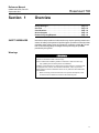
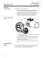
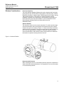
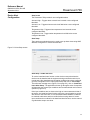
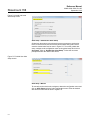
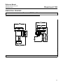
Reference Manual 00809-0100-4708, Rev AD September 2012 Rosemount 708 Wireless Acoustic Transmitter www.rosemount.com Reference Manual 00809-0100-4708, Rev AD September 2012 Rosemount 708 Rosemount 708 Wireless Acoustic Transmitter Rosemount 708 Hardware Revision HART® Device Revision Field Communicator Field Device Revision 1 1 Dev v1, DD v1 NOTICE Read this manual before working with the product. For personal and system safety, and for optimum product performance, make sure to thoroughly understand the contents before installing, using, or maintaining this product. The United States has two toll-free assistance numbers and one international number. Customer Central 1 800 999 9307 (7:00 a.m. to 7:00 p.m. CST) National Response Center 1 800 654 7768 (24 hours a day) Equipment service needs International 1 952 906 8888 The products described in this document are NOT designed for nuclear-qualified applications. Using non-nuclear qualified products in applications that require nuclear-qualified hardware or products may cause inaccurate readings. For information on Rosemount nuclear-qualified products, contact an Emerson Process Management Sales Representative. Reference Manual 00809-0100-4708, Rev AD September 2012 Rosemount 708 Explosions could result in death or serious injury: Installation of this transmitter in an explosive environment must be in accordance with the appropriate local, national, and international standards, codes, and practices. Please review the Product Certifications section for any restrictions associated with a safe installation. • Before connecting a Field Communicator in an explosive atmosphere, ensure the instruments are installed in accordance with intrinsically safe field wiring practices. This device complies with Part 15 of the FCC Rules. Operation is subject to the following conditions. This device may not cause harmful interference. This device must accept any interference received, including interference that may cause undesired operation. This device must be installed to ensure a minimum antenna separation distance of 20 cm (8 in.) from all persons. The Power Module may be replaced in a hazardous area. The Power Module has surface resistivity greater than one gigaohm and must be properly installed in the wireless device enclosure. Care must be taken during transportation to and from the point of installation to prevent a potential electrostatic charging hazard. Polymer enclosure has surface resistivity greater than one gigaohm. Care must be taken during transportation to and from the point of installation to prevent a potential electrostatic charging hazard. NOTICE The Rosemount 708 and all other wireless devices should be installed only after the Smart Wireless Gateway has been installed and is functioning properly. Wireless devices should also be powered up in order of proximity from the Smart Wireless Gateway, beginning with the closest. This will result in a simpler and faster network installation. NOTICE Shipping considerations for wireless products: The unit was shipped to you without the power module installed. Please remove the power module prior to shipping. Each power module contains one “D” size primary lithium battery. Primary lithium batteries are regulated in transportation by the U. S. Department of Transportation, and are also covered by IATA (International Air Transport Association), ICAO (International Civil Aviation Organization), and ARD (European Ground Transportation of Dangerous Goods). It is the responsibility of the shipper to ensure compliance with these or any other local requirements. Please consult current regulations and requirements before shipping. NOTICE The power module with the wireless unit contains one “D” size primary lithium/thionyl chloride battery. Each battery contains approximately 5.0 grams of lithium. Under normal conditions, the battery materials are self-contained and are not reactive as long as the battery and the pack integrity are maintained. Care should be taken to prevent thermal, electrical or mechanical damage. Contacts should be protected to prevent premature discharge. Battery hazards remain when cells are discharged. Power modules should be stored in a clean and dry area. For maximum battery life, storage temperature should not exceed 30 °C (86 °F). The Power Module may be replaced in a hazardous area. The Power Module has surface resistivity greater than one gigaohm and must be properly installed in the wireless device enclosure. Care must be taken during transportation to and from the point of installation to prevent electrostatic charge build-up. Reference Manual 00809-0100-4708, Rev AD September 2012 Rosemount 708 Table of Contents SECTION 1 Overview Safety Messages . . . . . . . . . . . . . . . . . . . . . . . . . . . . . . . . . . . . . . . . Warnings . . . . . . . . . . . . . . . . . . . . . . . . . . . . . . . . . . . . . . . . . . . . Overview. . . . . . . . . . . . . . . . . . . . . . . . . . . . . . . . . . . . . . . . . . . . . . . 708 Transmitter . . . . . . . . . . . . . . . . . . . . . . . . . . . . . . . . . . . . . . . Considerations . . . . . . . . . . . . . . . . . . . . . . . . . . . . . . . . . . . . . . . . . . General . . . . . . . . . . . . . . . . . . . . . . . . . . . . . . . . . . . . . . . . . . . . . Wireless Considerations . . . . . . . . . . . . . . . . . . . . . . . . . . . . . . . . Mechanical . . . . . . . . . . . . . . . . . . . . . . . . . . . . . . . . . . . . . . . . . . Electrical . . . . . . . . . . . . . . . . . . . . . . . . . . . . . . . . . . . . . . . . . . . . Environmental . . . . . . . . . . . . . . . . . . . . . . . . . . . . . . . . . . . . . . . . Service Support . . . . . . . . . . . . . . . . . . . . . . . . . . . . . . . . . . . . . . . . . Product Recycling/Disposal . . . . . . . . . . . . . . . . . . . . . . . . . . . . . . . . 1-1 1-1 1-2 1-2 1-2 1-2 1-3 1-4 1-4 1-4 1-5 1-6 SECTION 2 Configuration Safety Messages . . . . . . . . . . . . . . . . . . . . . . . . . . . . . . . . . . . . . . . . Warnings . . . . . . . . . . . . . . . . . . . . . . . . . . . . . . . . . . . . . . . . . . . . Device Configuration . . . . . . . . . . . . . . . . . . . . . . . . . . . . . . . . . . . . . Device Network Configuration . . . . . . . . . . . . . . . . . . . . . . . . . . . . . . AMS. . . . . . . . . . . . . . . . . . . . . . . . . . . . . . . . . . . . . . . . . . . . . . . . Field Communicator . . . . . . . . . . . . . . . . . . . . . . . . . . . . . . . . . . . Fast Key Sequence . . . . . . . . . . . . . . . . . . . . . . . . . . . . . . . . . . . . Remove Power Module . . . . . . . . . . . . . . . . . . . . . . . . . . . . . . . . . . . HART Menu Tree . . . . . . . . . . . . . . . . . . . . . . . . . . . . . . . . . . . . . . . . 2-1 2-1 2-1 2-2 2-2 2-2 2-3 2-3 2-4 SECTION 3 Mounting Safety Messages . . . . . . . . . . . . . . . . . . . . . . . . . . . . . . . . . . . . . . . . Warnings . . . . . . . . . . . . . . . . . . . . . . . . . . . . . . . . . . . . . . . . . . . . Mounting . . . . . . . . . . . . . . . . . . . . . . . . . . . . . . . . . . . . . . . . . . . . . . . Mounting Considerations. . . . . . . . . . . . . . . . . . . . . . . . . . . . . . . . 3-1 3-1 3-1 3-3 SECTION 4 Commissioning Safety Messages . . . . . . . . . . . . . . . . . . . . . . . . . . . . . . . . . . . . . . . . Warnings . . . . . . . . . . . . . . . . . . . . . . . . . . . . . . . . . . . . . . . . . . . . Verify Operation . . . . . . . . . . . . . . . . . . . . . . . . . . . . . . . . . . . . . . . . . Field Communicator . . . . . . . . . . . . . . . . . . . . . . . . . . . . . . . . . . . Smart Wireless Gateway . . . . . . . . . . . . . . . . . . . . . . . . . . . . . . . . Field Communicator Use . . . . . . . . . . . . . . . . . . . . . . . . . . . . . . . . 4-1 4-1 4-1 4-2 4-2 4-4 SECTION 5 Operation and Maintenance Safety Messages . . . . . . . . . . . . . . . . . . . . . . . . . . . . . . . . . . . . . . . . Warnings . . . . . . . . . . . . . . . . . . . . . . . . . . . . . . . . . . . . . . . . . . . . Operation . . . . . . . . . . . . . . . . . . . . . . . . . . . . . . . . . . . . . . . . . . . . . . Alerts. . . . . . . . . . . . . . . . . . . . . . . . . . . . . . . . . . . . . . . . . . . . . . . . . . Device Alert Configuration. . . . . . . . . . . . . . . . . . . . . . . . . . . . . . . Power Module Replacement. . . . . . . . . . . . . . . . . . . . . . . . . . . . . . . . 5-1 5-1 5-1 5-2 5-3 5-5 SECTION 6 Troubleshooting Overview. . . . . . . . . . . . . . . . . . . . . . . . . . . . . . . . . . . . . . . . . . . . . . . 6-1 Safety Messages . . . . . . . . . . . . . . . . . . . . . . . . . . . . . . . . . . . . . . . . 6-1 Warnings . . . . . . . . . . . . . . . . . . . . . . . . . . . . . . . . . . . . . . . . . . . . 6-1 TOC-1 Reference Manual 00809-0100-4708, Rev AD September 2012 APPENDIX A Specifications and Reference Data APPENDIX B Product Certifications APPENDIX C Recommended Practices Rosemount 708 Specifications . . . . . . . . . . . . . . . . . . . . . . . . . . . . . . . . . . . . . . . . . . . Functional Specifications. . . . . . . . . . . . . . . . . . . . . . . . . . . . . . . . Physical Specifications . . . . . . . . . . . . . . . . . . . . . . . . . . . . . . . . . Performance Specifications. . . . . . . . . . . . . . . . . . . . . . . . . . . . . . Wireless Output Specifications . . . . . . . . . . . . . . . . . . . . . . . . . . . Dimensional Drawings . . . . . . . . . . . . . . . . . . . . . . . . . . . . . . . . . . . . Ordering Information. . . . . . . . . . . . . . . . . . . . . . . . . . . . . . . . . . . . . . A-1 A-1 A-1 A-2 A-2 A-3 A-4 Approved Manufacturing Locations . . . . . . . . . . . . . . . . . . . . . . . . Telecommunication Compliance . . . . . . . . . . . . . . . . . . . . . . . . . . FCC and IC . . . . . . . . . . . . . . . . . . . . . . . . . . . . . . . . . . . . . . . . . . European Union Directive Information. . . . . . . . . . . . . . . . . . . . . . Ordinary Location Certification for FM. . . . . . . . . . . . . . . . . . . . . . Hazardous Locations Certificates . . . . . . . . . . . . . . . . . . . . . . . . . B-1 B-1 B-1 B-1 B-1 B-2 Effective Range . . . . . . . . . . . . . . . . . . . . . . . . . . . . . . . . . . . . . . . . . C-1 TOC-2 Reference Manual 00809-0100-4708, Rev AD September 2012 Section 1 Rosemount 708 Overview Safety Messages . . . . . . . . . . . . . . . . . . . . . . . . . . . . . . . . . . . . . page 1-1 Overview . . . . . . . . . . . . . . . . . . . . . . . . . . . . . . . . . . . . . . . . . . . page 1-2 Considerations . . . . . . . . . . . . . . . . . . . . . . . . . . . . . . . . . . . . . . page 1-2 Service Support . . . . . . . . . . . . . . . . . . . . . . . . . . . . . . . . . . . . . page 1-5 Product Recycling/Disposal . . . . . . . . . . . . . . . . . . . . . . . . . . . page 1-6 SAFETY MESSAGES Instructions and procedures in this section may require special precautions to ensure the safety of the personnel performing the operations. Information that potentially raises safety issues is indicated by a warning symbol ( ). Please refer to the following safety messages before performing an operation preceded by this symbol. Warnings Explosions could result in death or serious injury: Failure to follow these installation guidelines could result in death or serious injury: • Only qualified personnel should perform the installation. Installation of this transmitter in an explosive environment must be in accordance with the appropriate local, national, and international standards, codes, and practices. Please review the Product Certifications section for any restrictions associated with a safe installation. • Before connecting a Field Communicator in an explosive atmosphere, ensure the instruments are installed in accordance with intrinsically safe 1-1 Reference Manual 00809-0100-4708, Rev AD September 2012 Rosemount 708 OVERVIEW 708 Transmitter Benefits of the Rosemount 708 include: • Improved energy efficiency and environmental compliance with acoustic monitoring of steam traps and pressure relief valves • Gain instant visibility to all of your critical steam traps and PRVs through a non-intrusive, WirelessHART® monitoring system • Know you are backed by Emerson’s proven experience in Smart Wireless field instrumentation and expert technical support Figure 1-1. Rosemount 708 Wireless Acoustic Transmitter Overview 4 5 2 1 3 1 1. Power Module cover – Location of Power Module in device. Unscrew cap for access to Power Module. 2. Waveguide – Location of the acoustic and temperature sensors. 3. Electronics cover – The cover is sealed and cannot be removed. 4. Stainless steel mounting bands – Used to connect the acoustic transmitter to the process piping. 5. Pipe - The acoustic transmitter is installed directly to the process pipe. CONSIDERATIONS General 1-2 The acoustic transmitter detects the presence of acoustic noise along with sensor temperature. The Rosemount 708 converts the acoustic and temperature measurements into output data and alerts. Reference Manual 00809-0100-4708, Rev AD September 2012 Wireless Considerations Rosemount 708 Power Up Sequence The Smart Wireless Gateway (Gateway) should be installed and functioning properly before any wireless devices are powered. Install the power module, SmartPower Solutions, model number 701PGN green power module, into the 708 to power the device. This results in a simpler and faster network installation. Enabling Active Advertising on the Gateway ensures that new devices are able to join the network faster. For more information see the Smart Wireless Gateway Reference Manual (Document No. 00809-0200-4420). Antenna Position The antenna is internal to the acoustic transmitter. To achieve optimal range, orient the transmitter with the waveguide horizontal and the power module closest to the ground as shown in Figure 1-2. Good connectivity can also be achieved in other orientations. The antenna should also be approximately 1 m (3 ft.) from any large structure, building, or conductive surface to allow for clear communication to other devices. Refer to best practices for additional information on optimal mounting locations of device. Figure 1-2. Antenna Position Recommended Practices When mounting the device, recommended practices should be considered to achieve the best wireless performance. See Appendix C for more information on recommended practices. 1-3 Reference Manual 00809-0100-4708, Rev AD September 2012 Rosemount 708 Field Communicator Connections The Power Module needs to be installed in the device for the Field Communicator to interface with the 708. This transmitter uses the Green Power Module; please order model number 701PGNKF. Field communication with this device requires a HART-based Field Communicator using the correct 708 DD. Field communicator connections are located on the power module. The Power Module is keyed and can only be inserted in one orientation. Refer to Figure 1-3 for instructions on connecting the Field Communicator to the 708. Figure 1-3. Connection Diagram Mechanical Location When choosing an installation location and position, take into account access to the power module compartment for easy power module replacement. Electronics cover The electronics cover is sealed and cannot be removed. Do not attempt to unscrew the cover. Electrical Power Module The Rosemount 708 Wireless Acoustic Transmitter is self-powered. The power module contains one “D” size primary lithium/thionyl chloride battery. Each battery contains approximately 5.0 grams of lithium. Under normal conditions, the battery materials are self-contained and are not reactive as long as the battery and the power module are maintained. Care should be taken to prevent thermal, electrical, or mechanical damage. Contacts should be protected to prevent premature discharge. Use caution when handling the power module, it may be damaged if dropped from heights in excess of 6.10 m (20 ft). Environmental Verify that the operating atmosphere of the transmitter is consistent with the appropriate hazardous locations certifications. Temperature Effects The transmitter will operate within specifications for ambient temperatures between -40 and 85 °C (-40 and 185 °F). 1-4 Reference Manual 00809-0100-4708, Rev AD September 2012 Rosemount 708 Heat from the process is transferred to the transmitter housing. If the process temperature is high, the ambient temperature will need to be lower to account for heat transferred to the transmitter housing. See Table 1-1 for process temperature derating. Table 1-1. Temperature Derating Process Temperature (°C) Process Temperature (°F) Max Ambient (°C) Max Ambient (°F) 260 240 220 200 180 160 140 120 100 85 SERVICE SUPPORT 500 464 428 392 356 320 284 248 212 185 41 45 49 53 57 61 64 68 72 75 105.8 113 120.2 127.4 134.6 141.8 147.2 154.4 161.6 167 To expedite the return process outside of North America, contact your Emerson Process Management representative. Within the United States, call the Emerson Process Management Response Center toll-free number 1 800 654 7768. The center, which is available 24 hours a day, will assist you with any needed information or materials. The center will ask for product model and serial numbers, and will provide a Return Material Authorization (RMA) number. The center will also ask for the process material to which the product was last exposed. Individuals who handle products exposed to a hazardous substance can avoid injury if they are informed of, and understand, the hazard. If the product being returned was exposed to a hazardous substance as defined by OSHA, a copy of the required Material Safety Data Sheet (MSDS) for each hazardous substance identified must be included with the returned goods. SHIPPING CONSIDERATIONS FOR WIRELESS PRODUCTS (LITHIUM BATTERIES): The unit was shipped to you without the power module installed. Please remove the power module prior to shipping the unit. Primary lithium batteries (charged or discharged) are regulated during transportation by the U.S. Department of Transportation. They are also covered by IATA (International Air Transport Association), ICAO (International Civil Aviation Organization), and ARD (European Ground Transportation of Dangerous Goods). It is the responsibility of the shipper to ensure compliance with these or any other local requirements. Consult current regulations and requirements before shipping. 1-5 Reference Manual Rosemount 708 PRODUCT RECYCLING/DISPOSAL 1-6 00809-0100-4708, Rev AD September 2012 Recycling of equipment and packaging should be taken into consideration. The product and packaging should be disposed of in accordance with local and national legislation. Reference Manual 00809-0100-4708, Rev AD September 2012 Section 2 Rosemount 708 Configuration Safety Messages . . . . . . . . . . . . . . . . . . . . . . . . . . . . . . . . . page 2-1 Device Configuration . . . . . . . . . . . . . . . . . . . . . . . . . . . . . page 2-1 Device Network Configuration . . . . . . . . . . . . . . . . . . . . . page 2-2 Remove Power Module . . . . . . . . . . . . . . . . . . . . . . . . . . . page 2-3 HART Menu Tree . . . . . . . . . . . . . . . . . . . . . . . . . . . . . . . . . page 2-4 SAFETY MESSAGES Instructions and procedures in this section may require special precautions to ensure the safety of the personnel performing the operations. Information that potentially raises safety issues is indicated by a warning symbol ( ). Please refer to the following safety messages before performing an operation preceded by this symbol. Warnings Explosions could result in death or serious injury: Installation of this transmitter in an explosive environment must be in accordance with the appropriate local, national, and international standards, codes, and practices. Please review the Product Certifications section for any restrictions associated with a safe installation. • Before connecting a Field Communicator in an explosive atmosphere, ensure the instruments are installed in accordance with intrinsically safe wiring practices. This device complies with Part 15 of the FCC Rules. Operation is subject to the following conditions. This device may not cause harmful interference. This device must accept any interference received, including interference that may cause undesired operation. This device must be installed to ensure a minimum antenna separation distance of 20 cm (8 in.) from all persons. • DEVICE CONFIGURATION The Power Module may be replaced in a hazardous area. The Power Module has surface resistivity greater than one gigaohm and must be properly installed in the wireless device enclosure. Care must be taken during transportation to and from the point of installation to prevent a potential electrostatic charging hazard. Polymer enclosure has surface resistivity greater than one gigaohm. Care must be taken during transportation to and from the point of installation to prevent a potential electrostatic charging hazard. Remove the power module cover and connect to the HART communication terminals for configuration. The Rosemount 708 will receive HART communication from a handheld 375/475 Field Communicator (Field Communicator) or AMS Wireless Configurator. When using a Field Communicator, any configuration changes must be sent to the transmitter using the Send key (F2). AMS Wireless Configurator configuration changes are implemented when the Apply button is clicked. 2-1 Reference Manual 00809-0100-4708, Rev AD September 2012 Rosemount 708 AMS® Wireless Configurator AMS Wireless Configurator is capable of connecting to devices directly, using a HART modem, or remotely using the Gateway. To configure the Rosemount 708, double click (or right click and select Configure/Setup) on the device icon that will appear below either the HART modem or Gateway connection tree. DEVICE NETWORK CONFIGURATION In order to communicate with the Gateway, and ultimately the host system, the transmitter must be configured to communicate with the wireless network. Using a Field Communicator or AMS Wireless Configurator, enter the Network ID and Join Key so that they match the Network ID and Join Key of the Gateway and other devices in the network. If the network ID and join key are not the same as the Gateway, the acoustic transmitter will not communicate with the network. The Network ID and Join Key may be obtained from the Gateway on the Setup>Network>Settings page on the web server, shown in Figure 2-1. Figure 2-1. Gateway Network Settings AMS Right click on the acoustic transmitter and select Configure. When the menu opens, select Join Device to Network and follow the method to enter the Network ID and Join Key. Field Communicator The Network ID and Join Key may be changed in the wireless device by using the following Fast Key sequence. Set both Network ID and Join Key. 2-2 Function Key Sequence Menu Items Join Device to Network 2, 1, 2 Network ID, Set Join Key Reference Manual 00809-0100-4708, Rev AD September 2012 Fast Key Sequence Table 2-1. 708 Fast Key Sequence REMOVE POWER MODULE Rosemount 708 Table 2-1 lists the fast key sequence for common transmitter functions. Function Key Sequence Menu Items Device Information 2, 2, 5 Guided Setup 2, 1 Manual Setup 2, 2 Wireless 2, 2, 1 Tag, Long Tag, Descriptor, Message, Date, Country, SI Unit Control Basic Setup, Join Device to Network, Configure Update Rates, Alert Setup Wireless, Sensor, HART, Security, Device Information, Power Network ID, Join Device to Network, Broadcast Information After the sensor and network have been configured, remove the power module and replace the power module cover. The power module should be inserted only when the device is ready for commissioning. 2-3 Reference Manual Rosemount 708 HART MENU TREE Figure 2-2. Field Communicator Menu Tree 2-4 00809-0100-4708, Rev AD September 2012 Reference Manual 00809-0100-4708, Rev AD September 2012 Section 3 Rosemount 708 Mounting Safety Messages . . . . . . . . . . . . . . . . . . . . . . . . . . . . . . . . . page 3-1 Mounting . . . . . . . . . . . . . . . . . . . . . . . . . . . . . . . . . . . . . . . page 3-1 SAFETY MESSAGES Instructions and procedures in this section may require special precautions to ensure the safety of the personnel performing the operations. Information that potentially raises safety issues is indicated by a warning symbol ( ). Please refer to the following safety messages before performing an operation preceded by this symbol. Warnings Failure to follow these installation guidelines could result in death or serious injury: Only qualified personnel should perform the installation Explosions could result in death or serious injury. Before connecting a Field Communicator in an explosive atmosphere, make sure that the instruments are installed in accordance with intrinsically safe field wiring practices Verify that the operating atmosphere of the transmitter is consistent with the appropriate hazardous locations certifications This device complies with Part 15 of the FCC Rules. Operation is subject to the following conditions: This device may not cause harmful interference. This device must accept any interference received, including interference that may cause undesired operation. This device must be installed to ensure a minimum antenna separation distance of 20 cm (8 in.) from all persons. MOUNTING 1. Locate the 708 on a section of piping as close as possible to the equipment to be monitored. Align the waveguide of the transmitter as shown in Figure 3-1 and Figure 3-2. 2. The mounting location should be free of foreign matter and corrosion to ensure good contact between the piping and the waveguide. 3. Tighten each clamp to 10.2 N-m (90 in-lb). Trim the excess clamp band material to prevent unwanted acoustic noise. 4. If commissioning the device, install the Green Power Module (see Figure 3-3 on page 3-2). 5. Ensure that the Power Module cover is fully tightened to prevent moisture ingress. The lip of the polymer Power Module cover should be in contact with the surface of the polymer enclosure to ensure a proper seal. Do not over tighten. 3-1 Reference Manual Rosemount 708 00809-0100-4708, Rev AD September 2012 Figure 3-1. Transmitter Alignment Figure 3-2. Transmitter Alignment Top View Figure 3-3. Power Module Installation NOTE: Wireless devices should be powered up in order of proximity from the Gateway, beginning with the closest device to the Gateway. This will result in faster network formation. 3-2 Reference Manual 00809-0100-4708, Rev AD September 2012 Mounting Considerations Rosemount 708 1. Mounting bands should be inspected periodically and retightened if necessary. Some loosening may occur after initial installation due to thermal expansion/contraction. 2. The waveguide must be in direct contact with the pipe. 3. Insulate process piping to minimize ambient temperature effects (see Figure 3-4). Insulation thickness over the top of the waveguide foot should not exceed 2.54 cm (1-in). 4. For best results, mount the transmitter within 15.24 cm (6 in.) of the equipment to be monitored. 5. The stainless steel mounting bands could be affected by stress corrosion and potentially fail when in the presence of chlorides. 6. The transmitter should be installed such that steam or other high temperature fluids do not directly impinge the housing of the device. 7. If installing the device on a steam trap, the device should be installed on the upstream side of the trap. Figure 3-4. Piping, Insulation Side View 1 in. 3-3 Reference Manual Rosemount 708 3-4 00809-0100-4708, Rev AD September 2012 Reference Manual 00809-0100-4708, Rev AD September 2012 Section 4 Rosemount 708 Commissioning Safety Messages . . . . . . . . . . . . . . . . . . . . . . . . . . . . . . . . . page 4-1 Verify Operation . . . . . . . . . . . . . . . . . . . . . . . . . . . . . . . . . page 4-1 SAFETY MESSAGES Instructions and procedures in this section may require special precautions to ensure the safety of the personnel performing the operations. Information that potentially raises safety issues is indicated by a warning symbol ( ). Please refer to the following safety messages before performing an operation preceded by this symbol. Warnings Failure to follow these installation guidelines could result in death or serious injury. • Make sure only qualified personnel perform the installation. Explosions could result in death or serious injury: Installation of this transmitter in an explosive environment must be in accordance with the appropriate local, national, and international standards, codes, and practices. Please review the Product Certifications section for any restrictions associated with a safe installation. • Before connecting a Field Communicator in an explosive atmosphere, ensure the instruments are installed in accordance with intrinsically safe NOTE The Rosemount 708 and all other wireless devices should be installed only after the Gateway has been installed and is functioning properly. Wireless devices should be powered up in order of proximity from the Gateway, beginning with the device closest to the Gateway. This will result in a simpler and faster network installation. VERIFY OPERATION There are three ways to verify operation: using the Field Communicator, using the Gateway’s integrated web interface, or by using AMS® Suite Wireless Configurator or AMS Device Manager. If the Rosemount 708 was configured with the Network ID and Join Key, and sufficient time has passed, the transmitter will be connected to the network. If Network ID and Join Key were not configured, please reference Troubleshooting on page 4-3. NOTE It may take several minutes for the device to join the network. 4-1 Reference Manual 00809-0100-4708, Rev AD September 2012 Rosemount 708 Field Communicator For HART Wireless transmitter communication, a 708 DD is required. To obtain the latest DD, visit the Emerson Process Management Easy Upgrade site at: http://www2.emersonprocess.com/en-US/documentation/deviceinstallkits. The communication status may be verified in the wireless device using the following Fast Key sequence. Function Communications Smart Wireless Gateway Key Sequence 3, 4 Menu Items Join Status, Wireless Mode, Join Mode, Number of Available Neighbors, Number of Advertisements Heard, Number of Join Attempts Using the Gateway’s web interface, navigate to the Explorer page as shown in Figure 4-1. Locate the device in question and verify all status indicators are good (green). Figure 4-1. Smart Wireless Gateway Explorer page AMS® Suite Wireless Configurator When the device has joined the network, it will appear in the Device Manager as illustrated in Figure 4-2. For HART Wireless transmitter communication, a 708 DD is required. To obtain the latest DD, visit the Emerson Process Management Easy Upgrade site at: http://www2.emersonprocess.com/en-US/documentation/deviceinstallkits. Figure 4-2. Device Manager 4-2 Reference Manual 00809-0100-4708, Rev AD September 2012 Rosemount 708 NOTE SteamLogic software is provided for viewing steam trap status. Refer to the manual on the CD for more information. Troubleshooting If the device is not joined to the network after power up, verify the correct configuration of the Network ID and Join Key, and that Active Advertising has been enabled on the Gateway. The Network ID and Join Key in the device must match the Network ID and Join Key of the Gateway. The Network ID and Join Key may be obtained from the Gateway on the Setup>Network>Settings page of the web server (see Figure 4-3 on page 4-3). The Network ID and Join Key may be changed in the wireless device by following the Fast Key sequence shown below. Function Join Device to Network Key Sequence 2, 1, 2 Menu Items Network ID, Set Join Key Figure 4-3. Smart Wireless Gateway Network Settings 4-3 Reference Manual 00809-0100-4708, Rev AD September 2012 Rosemount 708 Field Communicator Use NOTE In order to communicate with a Field Communicator, power the 708 by connecting the Power Module. For more information on the Power Module, refer to the Power Module product data sheet (Document No 00813-0100-4701). Table 4-1 includes Fast Key sequences frequently used to interrogate and configure the device. Table 4-1. 708 Fast Key Sequence Figure 4-4. Field Communicator Connections 4-4 Function Key Sequence Device Information 2, 2, 5 Guided Setup 2, 1 Manual Setup 2, 2 Wireless 2, 2, 1 Menu Items Tag, Long Tag, Descriptor, Message, Date, Country, SI Unit Control Basic Setup, Join Device to Network, Configure Update Rates, Alert Setup Wireless, Sensor, HART, Security, Device Information, Power Network ID, Join Device to Network, Broadcast Information Reference Manual 00809-0100-4708, Rev AD September 2012 Section 5 Rosemount 708 Operation and Maintenance Safety Messages . . . . . . . . . . . . . . . . . . . . . . . . . . . . . . . . . page 5-1 Operation . . . . . . . . . . . . . . . . . . . . . . . . . . . . . . . . . . . . . . . page 5-1 Alerts . . . . . . . . . . . . . . . . . . . . . . . . . . . . . . . . . . . . . . . . . . page 5-2 Power Module Replacement . . . . . . . . . . . . . . . . . . . . . . . page 5-5 SAFETY MESSAGES Instructions and procedures in this section may require special precautions to ensure the safety of the personnel performing the operations. Information that potentially raises safety issues is indicated by a warning symbol ( ). Please refer to the following safety messages before performing an operation preceded by this symbol. Warnings Failure to follow these installation guidelines could result in death or serious injury. • Make sure only qualified personnel perform the installation. Explosions could result in death or serious injury. Installation of this transmitter in an explosive environment must be in accordance with the appropriate local, national, and international standards, codes, and practices. Please review the Product Certifications section for any restrictions associated with a safe installation. • OPERATION Before connecting a Field Communicator in an explosive atmosphere, ensure the instruments are installed in accordance with intrinsically safe The Rosemount 708 senses acoustic energy and temperature of the waveguide. The acoustic energy is reported in 'counts,' which are a relative indication of the magnitude of the acoustic energy sensed. The acoustic sensor used in the Rosemount 708 is sensitive to a broad range of spectral frequencies in order to work in many different installations. The acoustic measurement or “count” in the Rosemount 708 is an average of the broad range of frequencies. No additional signal processing is performed to isolate specific frequencies. This count information is used to determine the state of a steam trap, pressure relief valve, or other mechanical system. The device works similar to a discrete device, looking for a large change in noise level that is made during a leak or release. In the case of steam traps, SteamLogic software calculates the steam trap state based on the acoustic and temperature information published by the Rosemount 708. (Refer to SteamLogic manual for further information.) In the case of other equipment, the Rosemount 708 may be configured with alerts to detect and communicate changes in the state of the system being monitored. 5-1 Reference Manual Rosemount 708 ALERTS Figure 5-1. AMS Device Manager Overview Screen, Normal Conditions Figure 5-2. AMS Device Manager Overview Screen, Alert Conditions 5-2 00809-0100-4708, Rev AD September 2012 The Rosemount 708 can be configured to report alerts based on the acoustic and temperature level measured. The Rosemount 708 also reports diagnostic alerts when there is a device malfunction. For information on these alerts, refer to Section 6: Troubleshooting. The following figures show how the AMS Suite Intelligent Device Manager overview screen looks for each of the alert conditions. Reference Manual 00809-0100-4708, Rev AD September 2012 Device Alert Configuration Rosemount 708 Alert Levels The Rosemount 708 provides 4 user configurable alerts. Acoustic High - Triggers when acoustic level exceeds a user configured threshold. Acoustic Low - Triggers when acoustic level falls below a user configured threshold. Temperature High - Triggers when temperature level exceeds a user configured threshold. Temperature Low - Triggers when temperature level falls below a user configured threshold. Alert Setup There are three methods that can be used to set up these alerts using AMS Wireless Configurator or a field communicator. Figure 5-3. Alert Setup screen Alert Setup - Install and Learn To use the install and learn function on the device to setup the alerts the device must be installed and the equipment being monitored must be in its normal state. After installation and operating conditions have been confirmed, go to the configuration menu under guided setup and click on “alert setup.” This will launch a dialog menu (Figure 5-3 on page 5-3), click on “Install and Learn Alert Setup.” The application will then go through a series of steps that will determine the current input conditions and set alerts based on this normal operation (Figure 5-4). If the input conditions are too close to the high or low measurement limits of the device, the install and learn function will not be a good method to set the alert levels. If this is the case, it is recommended that installation conditions be checked and that the status is verified before moving ahead. If current input conditions do not allow for the install and learn function, use the manual or guided alert setup to set alerts. 5-3 Reference Manual 00809-0100-4708, Rev AD September 2012 Rosemount 708 Figure 5-4. Install and Learn Alert Setup screen Alert Setup - Guided User Alert Setup Guided user alert setup cycles through on-screen prompts to set the alert levels. At each screen, the current level will be shown along with a box to enter the desired alert level as seen in Figure 5-5. To use the guided alert setup, navigate to the configuration menu under guided setup and click on alert setup. Click on “Guided User Alert Setup.” Follow the on-screen prompts and enter the desired alert levels. Figure 5-5. Guided User Alert Setup screen Alert Setup - Manual To manually set the alert levels, navigate to alerts the configuration menu and click on Alert Setup under the main configuration menu. Enter the desired alert levels for each alert as seen in Figure 5-6. 5-4 Reference Manual 00809-0100-4708, Rev AD September 2012 Rosemount 708 Figure 5-6. Manual Alert Setup screen If a device is installed and shows an unexpected alert, verify the installation conditions. POWER MODULE REPLACEMENT Expected power module life is ten years at reference conditions.(1) When the power module needs to be replaced, remove the power module cover and the power module (SmartPower Solutions™, model number 701PGN green power module) then replace the power module and the cover. Ensure that the power module cover is fully tightened to prevent moisture ingress. The lip of the polymer power module cover should be in contact with the surface of the polymer enclosure to ensure a proper seal. Do not over tighten. Handling Considerations The green power module contains one “D” size primary lithium/thionyl chloride battery. Each battery contains approximately 5.0 grams of lithium. Under normal conditions, the battery materials are self-contained and are not reactive as long as the batteries and the battery pack integrity are maintained. Care should be taken to prevent thermal, electrical or mechanical damage. Contacts should be protected to prevent premature discharge. Use caution when handling the power module, it may be damaged if dropped from heights in excess of 6.1 meters (20 feet). Battery hazards remain when cells are discharged. Environmental Considerations As with any battery, local environmental rules and regulations should be consulted for proper management of spent batteries. If no specific requirements exist, recycling through a qualified recycler is encouraged. Consult the materials safety data sheet for battery specific information. (1) Reference conditions are 21 °C (70 °F), transmit rate of once per minute, and routing data for three additional network devices. 5-5 Reference Manual 00809-0100-4708, Rev AD September 2012 Rosemount 708 Shipping Considerations The unit was shipped to you without the power module installed. Please remove the power module prior to shipping. Each power module contains one “D” size primary lithium battery. Primary lithium batteries are regulated in transportation by the U.S. Department of Transportation, and are also covered by International Air Transport Association (IATA), International Civil Aviation Organization (ICAO), and European Ground Transportation of Dangerous Goods (ARD). It is the responsibility of the shipper to ensure compliance with these or any other local requirements. Please consult current regulations and requirements before shipping. 5-6 Reference Manual 00809-0100-4708, Rev AD September 2012 Section 6 Rosemount 708 Troubleshooting Overview . . . . . . . . . . . . . . . . . . . . . . . . . . . . . . . . . . . . . . . page 6-1 Safety Messages . . . . . . . . . . . . . . . . . . . . . . . . . . . . . . . . . page 6-1 OVERVIEW Table 6-1 provides summarized maintenance and troubleshooting suggestions for the most common operating problems. If you suspect malfunction despite the absence of any diagnostic messages, follow the procedures described here to verify that transmitter hardware and process connections are in good working order. Always deal with the most likely checkpoints first. SAFETY MESSAGES Instructions and procedures in this section may require special precautions to ensure the safety of the personnel performing the operations. Information that potentially raises safety issues is indicated by a warning symbol ( ). Please refer to the following safety messages before performing an operation preceded by this symbol. Warnings Failure to follow these installation guidelines could result in death or serious injury. • Make sure only qualified personnel perform the installation. Explosions could result in death or serious injury. Installation of this transmitter in an explosive environment must be in accordance with the appropriate local, national, and international standards, codes, and practices. Please review the Product Certifications section for any restrictions associated with a safe installation. • Before connecting a Field Communicator in an explosive atmosphere, ensure the instruments are installed in accordance with intrinsically safe 6-1 Reference Manual 00809-0100-4708, Rev AD September 2012 Rosemount 708 Table 6-1. Maintenance and Troubleshooting Suggestions Symptom Device Troubleshooting Electronics Failure Acoustics Failure WaveguideTemperature Failure Radio Failure Supply Voltage Failure Electronics Warning Acoustics exceeded the limits Electronics Temperature exceeded the limits Waveguide Temperature exceeded the limits Supply Voltage Low Database Memory Warning High Acoustic Level Low Acoustic Level High Temperature Level Low Temperature Level Simulation Active Short Battery Life Configuration Troubleshooting Cannot configure the device with 375 or AMS Wireless Troubleshooting Poor wireless connectivity Acoustic Transmitter not joining network Limited Bandwidth Error 6-2 Corrective Actions 1. Reset the device. 2. Reconfirm all configuration items in the device. 3. If the condition persists, replace the device. 1. Reset the device. 2. If the condition persists, replace the device. 1. Reset the device. 2. If the condition persists, replace the device. 1. Reset the device. 2. If the condition persists, replace the device. 1. Replace the Power Module. 2. If the condition persists, replace the device. 1. Reset the device. 2. Reconfirm all configuration items in the device. 3. If the condition persists, replace the device. 1. Check process for possible saturation condition. 2. Reset the device. 3. If the condition persists, replace the device. 1. Verify ambient temperature is within the transmitter’s range. 2. Reset the device. 3. If the condition persists, replace the device. 1. Verify process temperature is within the transmitter’s range. 2. Reset the device. 3. If the condition persists, replace the device. 1. Replace the Power Module. 1. Reset the device. 2. Reconfirm all configuration items in the device. 3. If logging dynamic data not needed, this advisory can be safely ignored. 1. Verify process conditions. Correct if they are outside of normal operating conditions. 2. Verify proper alert configuration. Reconfigure if necessary. 1. Verify process conditions. Correct if they are outside of normal operating conditions. 2. Verify proper alert configuration. Reconfigure if necessary. 1. Verify process conditions. Correct if they are outside of normal operating conditions. 2. Verify proper alert configuration. Reconfigure if necessary. 1. Verify process conditions. Correct if they are outside of normal operating conditions. 2. Verify proper alert configuration. Reconfigure if necessary. 1. Verify that simulation is no longer required. 2. Disable Simulation mode in Service Tools. 3. Reset the device. 1. Check that "Power Always On" mode is off . 2. Verify device is not installed in extreme temperatures. 3. Verify that device is not a network pinch point. 1. Power cycle the device. 2. Verify/replace power module. 3. Refer to AMS and/or handheld configuration tool manual for further troubleshooting. 1. Verify device oriented for optimal connections (See Section 1 of this document). 2. Verify wireless network best practices are followed (See Appendix C for more information). 1. Verify the device has power. 2. Verify the device is within effective communications range. 3. Verify the proper Network ID has been entered into the device. 4. See troubleshooting section of the Smart Wireless Gateway for more information (Document No. 00808-0200-4420). 1. Use the slowest acceptable update Rate. 2. Increase communication paths by adding more wireless points. 3. Check that the device has been online for at least an hour. 4. Create a new network with an additional Smart Wireless Gateway. Reference Manual 00809-0100-4708, Rev AD September 2012 Appendix A Rosemount 708 Specifications and Reference Data Specifications . . . . . . . . . . . . . . . . . . . . . . . . . . . . . . . . . . . page A-1 Dimensional Drawings . . . . . . . . . . . . . . . . . . . . . . . . . . . . page A-3 Ordering Information . . . . . . . . . . . . . . . . . . . . . . . . . . . . . page A-4 SPECIFICATIONS Functional Specifications Output IEC 62591 (WirelessHART) 2.4 GHz DSSS Humidity Limits 0–100% relative humidity Transmit Rate User selectable 1 second to 60 minutes Radio Frequency Power Output from Antenna Internal (WP option) antenna: Maximum of 10 mW (10 dBm) EIRP Physical Specifications Electrical Connections/Power Module • Replaceable, non-rechargeable, Intrinsically Safe Lithium-Thionyl Chloride power module pack with PBT/PC enclosure • Ten year power module life at reference conditions(1) Field Communicator Connections Communication Terminals - Clips permanently fixed to power module Materials of Construction Housing PBT/PC Cover O-ring Silicone Power Module Housing PBT/PC Wave Guide Machined 316L SST Mounting Transmitters are directly attached to process piping using two stainless steel mounting bands. (1) Reference conditions are 21 °C (70 °F), transmit rate of once per minute, and routing data for three additional network devices. A-1 Reference Manual 00809-0100-4708, Rev AD September 2012 Rosemount 708 Weight 708 with power module -0.595 kg (1.31 lb) 708 without power module - 0.445 kg (0.98 lb) Enclosure ratings NEMA 4X and IP66/67 Performance Specifications Vibration Effect Tested per the requirements of IEC60770-1 field or pipeline with high vibration level (10-60 Hz 0.21 mm displacement peak amplitude/60-2000 Hz 3g). Temperature Limits Ambient Limit -40 °C to 85 °C (-40 °F to 185 °F) Storage Limit -40 °C to 85 °C (-40 °F to 185 °F) Temperature Derating Process Temperature (°C) Max Ambient (°C) 260 240 220 200 180 160 140 120 100 85 41 45 49 53 57 61 64 68 72 75 ElectroMagnetic Compatibility (EMC) All Models: Meets all relevant requirements of EN 61326-2-3:2006 Wireless Output Specifications Acoustic Level 0-255 counts Temperature -40 to 260 °C (-40 to 500 °F) A-2 Reference Manual 00809-0100-4708, Rev AD September 2012 Rosemount 708 DIMENSIONAL DRAWINGS Rosemount 708 Direct Mount Dimensions are in inches (millimeters) A-3 Reference Manual Rosemount 708 00809-0100-4708, Rev AD September 2012 ORDERING INFORMATION Table A-1. Rosemount 708 Acoustic Transmitter Ordering Information ★ The Standard offering represents the most common options. The starred options (★) should be selected for best delivery. __The Expanded offering is subject to additional delivery lead time. Model Product Description Standard 708 Acoustic Transmitter Standard ★ Output Protocol Standard X Wireless Standard ★ Measurement Standard 1 2 Steam Traps with SteamLogic software Other Measurements Standard ★ ★ Engineered Polymer Standard ★ Housing Standard P Waveguide Configuration Standard A1 Acoustic Waveguide Standard ★ Product Certifications Standard NA I1 I2 I5 I6 I7 No Hazardous Location Approval ATEX Intrinsic Safety INMETRO Intrinsic Safety FM Intrinsically Safe CSA Intrinsically Safe IECEx Intrinsic Safety Standard ★ ★ ★ ★ ★ ★ Mounting Hardware Standard NA00 HC01 HC02 HC03 No Mounting Hardware Stainless Steel Mounting Band, Pipe size 1/2 to 2-1/2-in. Stainless Steel Mounting Band, Pipe size 3-in. to 4-in. Stainless Steel Mounting Band, Pipe size 4-in. to 10-in. Standard ★ ★ ★ ★ Wireless Options (Include with selected model number) Wireless Update Rate, Operating Frequency and Protocol Standard WA3 User Configurable Update Rate, 2.4 GHz DSSS, IEC 62591 (WirelessHART) Standard ★ Omnidirectional Wireless Antenna and SmartPower Solutions Standard WP5(1) Internal Antenna, Compatible with Green Power Module (I.S. Power Module Sold Separately) Standard ★ Configuration Standard C1 Factory Configure Date, Descriptor, Message Fields and Wireless Parameters Typical Model Number: 708 X 1 P A1 NA HC01 WA3 WP5 (1) Power module must be shipped separately, order 701PGNKF. A-4 Standard ★ Reference Manual 00809-0100-4708, Rev AD September 2012 Appendix B Rosemount 708 Product Certifications Approved Manufacturing Locations . . . . . . . . . . . . . . . . . page B-1 Telecommunication Compliance . . . . . . . . . . . . . . . . . . . . page B-1 FCC and IC . . . . . . . . . . . . . . . . . . . . . . . . . . . . . . . . . . . . . page B-1 European Union Directive Information . . . . . . . . . . . . . . . page B-1 Ordinary Location Certification for FM . . . . . . . . . . . . . . . page B-1 Hazardous Locations Certificates . . . . . . . . . . . . . . . . . . . page B-2 Approved Manufacturing Locations Rosemount Inc. - Chanhassen, Minnesota, USA Emerson Process Management GmbH & Co. - Karlstein, Germany Emerson Process Management Asia Pacific Private Limited - Singapore Telecommunication Compliance All wireless devices require certification to ensure that they adhere to regulations regarding the use of the RF spectrum. Nearly every country requires this type of product certification. Emerson is working with governmental agencies around the world to supply fully compliant products and remove the rise of violating country directives or laws governing wireless device usage. FCC and IC This device complies with Part 15 of the FCC Rules. Operation is subject to the following conditions: This device may not cause harmful interference. This device must accept any interference received, including interference that may cause undesired operation. This device must be installed to ensure a minimum antenna separation distance of 20 cm from all persons. European Union Directive Information The EC Declaration of Conformity for all applicable European directives for this product can be found on www.rosemount.com. A hard copy may be obtained by contacting your local sales representative. ATEX Directive (94/9/EC) Emerson Process Management complies with the ATEX Directive. Electro Magnetic Compatibility (EMC) (2004/108/EEC) EN 61326-1; 2006 EN 61326-2-3; 2006 Radio and Telecommunications Terminal Equipment Directive (R & TTE) (1999/5/EC) Emerson Process Management complies with the R&TTE Directive. Ordinary Location Certification for FM As standard, the transmitter has been examined and tested to determine that the design meets basic electrical, mechanical, and fire protection requirements by FM Approvals, a nationally recognized testing laboratory (NRTL) as accredited by the Federal Occupational Safety and Health Administration (OSHA). B-1 Reference Manual 00809-0100-4708, Rev AD September 2012 Rosemount 708 Hazardous Locations Certificates North American Certifications Factory Mutual (FM) Approvals I5 Intrinsically Safe Intrinsically Safe for Class I, Division 1, Groups A, B, C, and D Zone Marking: Class I, Zone 0, AEx ia llC Temperature Codes T4 (Tamb = -40 to 70 °C) Ambient temperature limits: -40 to 70 °C For use with SmartPower Solutions, model number 701PGN green power module only. Enclosure Type 4X / IP66/67 Special Conditions for Safe Use (X): 1. The Rosemount 708 Wireless Acoustic Transmitter shall only be used with the SmartPower Solutions, model number 701PGN green power module. 2. Potential Electrostatic charging Hazard – See Instructions. Standards: FM3600:1998 FM3610:2010 ANSI/NEMA 250 ANSI/IEC60529:2004 CSA International I6 CSA Intrinsically Safe Certificate No: 2439890 Applicable Standards: CSA std. C22.2 no. 142-M1987, CSA Std. C22.2 No. 157-92 Intrinsically Safe for Class I, Division 1, Groups A, B, C, and D T3C (-40 °CTamb 70 °C) Intrinsically safe when installed according to Rosemount Drawing 00708-1001 For use with SmartPower Solutions, model number 701PGN green power module only. Enclosure Type 4X, IP66/67 European Certifications I1 ATEX Intrinsic Safety Certificate No.: BASEEFA11ATEX0174X II 1G Ex ia IIC T4 (Ta = -40 °C Tamb 70 °C) IP66/67 For use with SmartPower Solutions, model number 701PGN green power module only. 1180 Special Conditions for Safe Use (X): 1. The engineered polymer enclosure of the Rosemount 708 may constitute a potential electrostatic ignition risk and must not be rubbed or cleaned with a dry cloth. Standards: EN60079-0:2009 EN60079-11:2007 B-2 Reference Manual 00809-0100-4708, Rev AD September 2012 Rosemount 708 IECEx System Certifications I7 IECEx Intrinsic Safety Certificate No.: IECExBAS 11.0091X Ex ia IIC Ga (Ta = -40 °C Tamb 70 °C) IP66/67 For use with SmartPower Solutions, model number 701PGN green power module only. 1180 Special Conditions for Safe Use (X): 1. The engineered polymer enclosure of the Rosemount 708 may constitute a potential electrostatic ignition risk and must not be rubbed or cleaned with a dry cloth. Standards: EC60079-0:2007-10 IEC60079-11:2006 Brazilian Certifications I2 Certificate No.: NCC 12.0817X INMETRO marking: Ex ia IIC T4 Ga Electric parameters: Un=3,9Vcc /In=2,313A / Pn=2,255W / Co=0 /Lo=0 Safe Use Conditions (X): The enclosure may constitute a potential electrostatic ignition risk and must not be rubbed or cleaned with dry cloth. B-3 Reference Manual Rosemount 708 00809-0100-4708, Rev AD September 2012 c Master – PRINTED COPIES ARE UNCONTROLLED – Rosemount Proprietary Figure B-1. Rosemount 708 FM Intrinsically Safe Installation Drawing B-4 Reference Manual 00809-0100-4708, Rev AD September 2012 Appendix C Rosemount 708 Recommended Practices Effective Range . . . . . . . . . . . . . . . . . . . . . . . . . . . . . . . . . . page C-1 All recommended practices should be followed to ensure highest data reliability. Deviation from those best practices may require device repeaters in the network to maintain 99% data reliability. The following are guidelines to achieve the best possible Smart Wireless Network. EFFECTIVE RANGE 1. Each wireless network field should be scoped to a single process unit. 2. Minimize the number of hops to the Gateway in order to reduce latency. Contain a minimum of five wireless instruments within effective range of the Smart Wireless Gateway. 3. Have at minimum three devices with potential communication paths. For stronger performance, increase the required number of wireless neighbor devices to four or five. This increases the number of potential paths and thus optimized network performance. 4. Have 25 percent of wireless instruments in the network within range of Smart Wireless Gateway. Other enhancing modifications include creating a higher percentage of devices within effective range of the gateway to 35 percent or more. This clusters more devices around the gateway and ensures fewer hops and more bandwidth available to WirelessHART devices with fast scan rates. 5. Keep path distance from Gateway to a minimum. For better performance, the path typically is within range of one to two hops. This will utilize path redundancy and create very short transit times. 6. Effective range is determined by type of process unit and the density of the infrastructure that surrounds the network. Heavy Obstruction: 100 ft. (30 m). Typical heavy density plant environment. Cannot drive a truck or equipment through. Medium Obstruction: 250 ft. (76 m). Typical light process areas, lots of space between equipment and infrastructure. Light Obstruction: 500 ft. (152 m). Typical of tank farms. Despite tanks being big obstructions themselves, lots of space between and above makes for good RF propagation. Line of Sight: 750 ft. (230 m). No obstructions between WirelessHART devices and devices mounted a minimum of 6 ft. (2 m) above ground or obstructions. For examples and complete explanations, refer to the IEC62591 WirelessHART System Engineering Guide: http://www2.emersonprocess.com/siteadmincenter/PM%20Central%20Web %20Documents/EMR_WirelessHART_SysEngGuide.pdf C-1 Reference Manual Rosemount 708 C-2 00809-0100-4708, Rev AD September 2012 Reference Manual 00809-0100-4708, Rev AC September 2012 The Emerson logo is a trade mark and service mark of Emerson Electric Co. Rosemount and the Rosemount logotype are registered trademarks of Rosemount Inc. PlantWeb is a registered trademark of one of the Emerson Process Management group of companies. HART is a registered trademark of the HART Communication Foundation. Lexan and Noryl are registered trademark of General Electric. All other marks are the property of their respective owners. Standard Terms and Conditions of Sale can be found at www.rosemount.com/terms_of_sale © 2012 Rosemount Inc. All rights reserved. Emerson Process Management Rosemount Inc. 8200 Market Boulevard Chanhassen, MN 55317 USA T (U.S.) 1 800 999 9307 T (International) 952 906 8888 F 952 906 8889 www.rosemount.com 00809-0100-4708 Rev AD, 9/12 Rosemount Temperature GmbH Frankenstrasse 21 63791 Karlstein Germany T 49 6188 992 0 F 49 6188 992 112 Emerson Process Management Asia Pacific Private Limited 1 Pandan Crescent Singapore 128461 T (65) 6777 8211 F (65) 6777 0947 [email protected]