1
Instruction Manual
PN 51-399VP/rev.B
January 2005
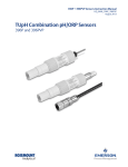
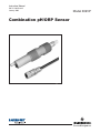
Combination pH/ORP Sensor
Model 399VP
ESSENTIAL INSTRUCTIONS
READ THIS PAGE BEFORE PROCEEDING!
Rosemount Analytical designs, manufactures, and tests its products to
meet many national and international standards. Because these instruments are sophisticated technical products, you must properly install, use,
and maintain them to ensure they continue to operate within their normal
specifications. The following instructions must be adhered to and integrated into your safety program when installing, using, and maintaining
Rosemount Analytical products. Failure to follow the proper instructions
may cause any one of the following situations to occur: Loss of life; personal injury; property damage; damage to this instrument; and warranty
invalidation.
• Read all instructions prior to installing, operating, and servicing the product. If this Instruction Manual is not the correct manual, telephone 1-800654-7768 and the requested manual will be provided. Save this
Instruction Manual for future reference.
• If you do not understand any of the instructions, contact your Rosemount
representative for clarification.
• Follow all warnings, cautions, and instructions marked on and supplied
with the product.
• Inform and educate your personnel in the proper installation, operation,
and maintenance of the product.
• Install your equipment as specified in the Installation Instructions of the
appropriate Instruction Manual and per applicable local and national
codes. Connect all products to the proper electrical and pressure
sources.
• To ensure proper performance, use qualified personnel to install, operate, update, program, and maintain the product.
• When replacement parts are required, ensure that qualified people use
replacement parts specified by Rosemount. Unauthorized parts and procedures can affect the product’s performance and place the safe operation of your process at risk. Look alike substitutions may result in fire,
electrical hazards, or improper operation.
• Ensure that all equipment doors are closed and protective covers are in
place, except when maintenance is being performed by qualified persons, to prevent electrical shock and personal injury.
DANGER
HAZARDOUS AREA INSTALLATION
Installations near flammable liquids or in hazardous area locations must be carefully evaluated by qualified on site safety personnel. This
sensor is not Intrinsically Safe or Explosion
Proof.
To secure and maintain an intrinsically safe
installation, the certified safety barrier, transmitter, and sensor combination must be
used. The installation system must comply
with the governing approval agency (FM,
CSA or BASEEFA/CENELEC) hazardous
area classification requirements. Consult your
analyzer/transmitter instruction manual for
details.
Proper installation, operation and servicing of
this sensor in a Hazardous Area Installation is
entirely the responsibility of the user.
CAUTION
SENSOR/PROCESS
APPLICATION COMPATIBILITY
The wetted sensor materials may not be
compatible with process composition
and operating conditions. Application
compatibility is entirely the responsibility of the user.
About This Document
This manual contains instructions for installation and operation of the Model 399VP Combination
pH/ORP Sensor. The following list provides notes concerning all revisions of this document.
Rev. Level
Date
Notes
0
10/00
This is the initial release of the product manual. The manual has been reformatted to reflect the
Emerson documentation style and updated to reflect any changes in the product offering.
A
7/02
Added 1055 wiring diagrams.
B
1/05
Update flow cell info on pages 2 & 6.
Emerson Process Management
Rosemount Analytical Inc.
2400 Barranca Parkway
Irvine, CA 92606 USA
Tel: (949) 757-8500
Fax: (949) 474-7250
http://www.raihome.com
© Rosemount Analytical Inc. 2005
MODEL 399VP pH/ORP
TABLE OF CONTENTS
MODEL 399VP pH/ORP SENSOR
TABLE OF CONTENTS
SECTION
1.0
1.1
1.2
1.3
TITLE
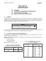
DESCRIPTION AND SPECIFICATIONS ..........................................................
Features and Applications.................................................................................
Physical Specifications......................................................................................
Ordering Information .........................................................................................
PAGE
1
1
1
2
2.0
2.1
2.2
2.3
2.4
2.5
INSTALLATION ................................................................................................
Unpacking and Inspection .................................................................................
Mounting ...........................................................................................................
Flow-Through Installation ..................................................................................
Insertion Installations ........................................................................................
Submersion Installations ..................................................................................
3
3
3
5
6
7
3.0
WIRING.............................................................................................................
10
4.0
4.1
4.2
4.3
START-UP AND CALIBRATION ......................................................................
Sensor Preparation ...........................................................................................
pH Calibration ...................................................................................................
ORP Calibration ................................................................................................
19
19
19
20
5.0
5.1
5.2
5.3
5.4
MAINTENANCE................................................................................................
General .............................................................................................................
Automatic Temperature Compensator ..............................................................
pH Electrode Cleaning ......................................................................................
ORP Platinum Electrode Check ........................................................................
21
21
21
22
22
6.0
TROUBLESHOOTING......................................................................................
23
7.0
RETURN OF MATERIAL ..................................................................................
24
i
MODEL 399VP pH/ORP
TABLE OF CONTENTS
MODEL 399VP pH/ORP SENSOR
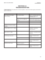
LIST OF FIGURES
Figure No.
2-1
2-2
2-3
2-4
2-5
2-6
2-7
2-8
3-1
3-2
3-3
3-4
3-5
3-6
3-7
3-8
3-9
3-10
3-11
3-12
3-13
3-14
3-15
3-16
3-17
3-18
3-19
3-20
3-21
3-22
3-23
Title
Sensor Dimensions ...........................................................................................
Model 399VP Shown in Various Flow-Through Installations.............................
Model 399VP Shown in Low Flow Cell Assembly .............................................
Model 399VP Shown in Various Insertion Installations .....................................
Model 399VP With Insertion Adapter ................................................................
Sensor Shown in Handrail Mounting Assembly ................................................
Jet Spray Cleaner Used With Model 399VP .....................................................
Junction Box and Pipe Mounting Accessory .....................................................
Wire and Connector Pin Functions ...................................................................
Model 81 Wiring ................................................................................................
Model 1181 Wiring ............................................................................................
Model 54 Wiring Through a Remote Junction Box............................................
Model 54 Wiring ................................................................................................
Model 2081 Wiring ............................................................................................
Model 1181, 1050/1060, 1003/1023 Wiring Through a Remote Junction Box ..
Model 2081 Wiring Through a Remote Junction Box........................................
Model 81 Wiring Through a Remote Junction Box............................................
Model 3081 and 4081 Wiring Through a Remote Junction Box........................
Model 1055-22-32 Wiring..................................................................................
Model 3081 and 4081 Wiring ............................................................................
Model 1054 Wiring ............................................................................................
Model 1054A/B and 2054 Wiring ......................................................................
Model 1054 Wiring Through a Remote Junction Box........................................
Model 1054A/B and 2054 Wiring Through a Remote Junction Box..................
Model SCL-(P/Q) Wiring ...................................................................................
Model 2700 Wiring ............................................................................................
Model 54epH Wiring..........................................................................................
Model 1055-22-32 Wiring Through Remote Junction Boxes ............................
Wiring Model 399VP-09 to Model 1055 (Pipe/Wall Mount) ...............................
Wiring Model 399VP-09 to Model 1055 (Panel Mount).....................................
Preparation of Raw Connecting Cable ..............................................................
Page
4
5
6
6
7
8
9
9
11
11
11
11
12
12
12
12
13
13
13
13
14
14
14
14
15
15
15
15
16
17
18
LIST OF TABLES
Table No.
3-1
4-1
5-1
5-2
Title
Page
Remote Junction Box and Extension Cable Part Numbers...............................
ORP of Saturated Quinhydrone Solutions (in Millivolts)....................................
Ro & R1 Values for Temperature Compensation Elements ..............................
Temperature vs. Resistance of Auto TC Element..............................................
ii
10
20
21
21
MODEL 399VP pH/ORP SENSOR
SECTION 1.0
DESCRIPTION AND SPECIFICATIONS
SECTION 1.0.
DESCRIPTION AND SPECIFICATIONS
1.1
1.2
1.3
FEATURES AND APPLICATIONS
PHYSICAL SPECIFICATIONS
ORDERING INFORMATION
1.1 FEATURES AND APPLICATIONS
1.2 PHYSICAL SPECIFICATIONS
The Rosemount Analytical Model 399VP Sensor measures the pH or the Oxidation Reduction Potential
(ORP) of aqueous solutions in pipelines, open tanks,
or ponds. It is suitable for virtually all applications
where a low cost sensor is required. The combination
electrode features a ceramic junction constructed in
an annular design around the pH/ORP sensitive
membrane. The double or triple junction reference
cell configuration is resistant to process solutions
containing ammonia, chlorine, cyanides, sulfides, or
other poisoning ions.
The glass electrode is housed in a molded Tefzel
body and sealed with Viton1 O-rings to guard against
process leakage. The cable end of the sensor is also
sealed, eliminating cable shorts caused by exposure
to moisture. This construction makes for a highly
chemical resistant disposable sensor and does not
require electrolyte replenishment.
The custom glass electrode is available with either a
standard hemi bulb or an optional flat bulb to best
meet your application needs. Flat glass is advantageous in abrasive or coating applications that etch or
build up on the glass respectively. In coating applications, such as slurries, the flat surface allows the
process flow to act as a scrubbing agent to reduce
coating and maintenance whereas in abrasive applications pitting from silicates and other similar materials is minimized by the flat surface to provide longer
life. The hemi bulb is ideal for general purpose use
and for those processes requiring greater accuracy
over the entire pH range
Installation is easily achieved through the wide variety
of mounting configurations. The Model 399VP features 1 in. (MNPT) front and rear facing connections
for insertion, submersion or flow through pH and ORP
applications.
Materials of Construction: Tefzel, glass, ceramic
and Viton (also, Platinum for ORP sensor)
Process Connections: 1 in. MNPT
Interconnecting Cable: None - must use mating VP
cable
Measured Range: pH: 0-14*
ORP: –1500 -+1500mV
*Percent Linearity over pH range:
1-2 pH
2-12 pH
12-13 pH
Hemi Bulb
94%
99%
97%
Flat Bulb
93%
98%
95%
Temperature Compensation: Automatic 0 to 85°C
(32° to 185°F) (Temperature compensation is not
required for 399 ORP when used with Models 1060,
1023 or 1181 ORP)
Maximum Pressure: 790 kPa abs (100 psig) at 65°C
(Refer to Graph A below)
Weight/Shipping Weight: 0.45 kg/0.9 kg (1 lb/2 lb)
1
Registered trademarks of E. I. du Pont de Nemours and Company.
GRAPH A. Pressure/Temperature Limitations
for Model 399VP
1
MODEL 399VP pH/ORP SENSOR
SECTION 1.0
DESCRIPTION AND SPECIFICATIONS
1.3 ORDERING INFORMATION
The Model 399VP pH/ORP Sensor is available with custom glass electrodes housed in a molded Tefzel body with
1 in. MNPT threads suitable for insertion, submersion or flow through installation. The sensor includes a general
purpose hemi bulb pH electrode (flat bulb optional) or a platinum ORP electrode and a double or triple junction gel
filled reference electrode. Automatic temperature compensation is standard with the Model 399VP pH, but is not
required on the Model 399VP ORP (except when used with the Model 1054A ORP Microprocessor Analyzer). The
399VP is offered with the Variopol (VP) connector and uses a mating VP cable (purchased separately). A remote
preamplifier must be used with this sensor.
MODEL
399VP
pH/ORP SENSOR
Code
02
09
399VP pH (GPLR hemi bulb) Preamplifier/Cable (Required Selection)
3K ohm TC (Models 1181, 1050, and 1003)
Pt100 TC (Models 54pH, 1054A/B, 1055, 2054, 2081 pH, 81, 3081, and 4081)
Code
11
15
71
Glass Type (optional - choose one; not valid with special application codes)
High pH
HF Resistant
GPLR Flat bulb
Code
301
302
Special Applications - valid with only standard hemi glass (optional - choose one)
Low ionic strength water
Heavy reference poisoning ions (triple reference junction)
303
33
PN
23645-06
23645-07
High temperature spikes or Low temperature storage
ORP sensor
Mating VP Connector Cable (required for all new installations)
15 ft cable with mating VP connector, prepped with BNC on analyzer end
15 ft cable with mating VP connector, prepped without BNC on analyzer end
FOR FIRST TIME 399VP* INSTALLATIONS, WE RECOMMEND USING THE FOLLOWING GUIDE:
1. Mounting Accessories (optional)
Choose one: PN 23242-02, Mounting adapter kit, 1/2 in. MNPT process connection, 1 in. x 3/4 in. sensor adapter
PN 915240-03, PVC flow through tee, 3/4 in. NPT process connection
PN 915240-04, PVC flow through tee, 1 in. NPT process connection
PN 915240-05, PVC flow through tee, 1-1/2 in. NPT process connection
PN 24091-00, Acrylic low flow cell
PN 2002011, 1-1/2 in. CPVC tee with 1-in. FNPT connection
PN 9330022, Pipe mount union, 1 in. x 1 in. CPVC (for sensor to analyzer distance extension)
PN 11275-01, Sensor handrail assembly
PN 1000857, Handrail mounting kit (pipe and sensor coupling supplied by others)
2. Junction Boxes (optional)
Remote Junction Boxes (to extend sensor to analyzer distances)
Choose one: PN 23555-00, includes preamplifier for Models 54, 81, 3081, 4081; NEMA 4X
PN 22719-02, Weatherproof junction box for cable extension
PN 23309-03, use with 1181 and 1050 compatible preamplifier
PN 23309-04, use with 1054/A/B, 2054, 2081 compatible preamplifier
3. Preamplifiers (used to amplify signal when mounting sensor further than 15 ft from the analyzer)
Choose one: PN 22698-02, Plug in preamplifier, 1181/1050 compatible (use with junction box PN 23309-03)
PN 22698-03, Plug in preamplifier, 1054/1054A/1054B/2054/ 2081 compatible (use with junction box PN 23309-04)
4. Extension cables (used with remote junction boxes)
Choose one: PN 23646-01, 11 conductor cable, shielded, prepped
PN 9200000, 4 conductor cable, shielded, unprepped
5. Other optional accessories
Choose one: PN 12707-00, Jet spray cleaner
PN 2001492, Stainless steel tag, specify marking (formerly Code -11)
PN 9210012, Buffer solution, 16 oz, 4.01 pH
PN 9210013, Buffer solution, 16 oz, 6.86 pH
PN 9210014, Buffer solution, 16 oz, 9.18 pH
PN 22698-00, Plug-in preamplifier, 1003 compatible
2
* Also requires mating VP cable — see 399VP Ordering Information above.
MODEL 399VP pH/ORP SENSOR
SECTION 2.0
INSTALLATION
SECTION 2.0.
INSTALLATION
2.1
2.2
2.3
2.4
2.5
UNPACKING AND INSPECTION
MOUNTING
FLOW-THROUGH INSTALLATIONS
INSERTION INSTALLATIONS
SUBMERSION INSTALLATIONS
2.1 UNPACKING AND INSPECTION.
2.2 MOUNTING.
Inspect the carton for any damage. If damage is
detected, contact the carrier immediately. Inspect the
hardware. Make sure all the items on the packing list
are present and in good condition. Notify the factory
if any part is missing. If the sensor is in satisfactory
condition, proceed to Section 2.2, Mounting.
NOTE
Save the packing cartons and materials as
most carriers require proof of damage due to
mishandling, etc. Also, if it is necessary to
return the sensor to the factory, you must pack
the sensor in the same manner as it was
received. Refer to Section 7.0 for instructions.
If storing the sensor, the vinyl boot should be
filled with pH buffer solution (pH 4 buffer recommended) and replaced on sensor tip until
ready to use.
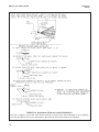
The sensor has been designed to be located in
industrial process environments. Temperature and
pressure limitations must not be exceeded at any
time. A pertinent caution label is attached to the sensor. Please do not remove the label. See Figure 2-1.
CAUTION
Buffer solution in the vinyl boot may cause
skin or eye irritation.
NOTE
Glass electrode must be wetted at all times (in
storage and in line) to maximize sensor life.
CAUTION
Internal electrolyte fill solution may cause skin
or eye irritation.
Mounting Guidelines:
1. Shake down the sensor to remove any air bubbles that may be present inside the tip of the pH
glass.
2. Do not install the sensor horizontally. The sensor
must be at a minimum of 10° off the horizontal
(sensor glass bulb pointing down) to ensure
accuracy.
3. Do not install the sensor upside down.
4. Air bubbles may become trapped on the sensor
glass bulb. This problem is most commonly
encountered in areas of low flow or during calibration. Shake the probe while immersed in solution to remove bubbles.
In most cases, the pH sensor can simply be installed
as shipped, and readings with an accuracy of ± 0.6
pH may be obtained. To obtain greater accuracy or
to verify proper operation, the sensor must be calibrated together with its compatible analyzer or transmitter.
3
MODEL 399VP pH/ORP SENSOR
SECTION 2.0
INSTALLATION
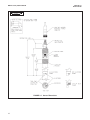
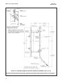
INCH
MILLIMETER
FIGURE 2-1. Sensor Dimensions
4
MODEL 399VP pH/ORP SENSOR
SECTION 2.0
INSTALLATION
2.3 FLOW-THROUGH INSTALLATIONS.
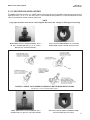
The Model 399VP Sensor has a 1 in. MNPT process connection at the front and back end of the sensor for mounting directly into a 1 in. or 1½ in. tee. See Figure 2-2 for installation configurations. It is recommended that shut-off
valves be provided for sensor removal and service.
NOTE
Large pipe wrenches must not be used to tighten the sensor into a flange or other type of mounting.
Model 399VP shown in Tee PN 915240-03, -04, or 05. Tee is available with 3/4 in., 1 in., or 1-1/2 in.
NPT process connection threads.
Side view of Tee PN 915240-03, -04, or -05 with
Model 399VP shown in middle of process flow.
FIGURE 2-2. MODEL 399VP SHOWN IN VARIOUS FLOW THROUGH INSTALLATIONS
See Section 1.3 for a complete listing of tees.
Model 399VP shown in Tee PN 2002011. Tee is
available with 1 in. process connection threads.
Side view of Tee PN 2002011 with Model 399VP
shown in middle of process flow.
5
MODEL 399VP pH/ORP SENSOR
SECTION 2.0
INSTALLATION
The see-through flow cell is
perfect for processes where
flow regulation is desired.
Tubing (1/4 inch) is needed for
connection to the process or
sample stream.
FIGURE 2-3. MODEL 399VP SHOWN IN LOW FLOW CELL ASSEMBLY (PN 23728-00)
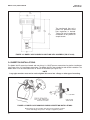
2.4 INSERTION INSTALLATIONS.
The Model 399VP sensor has forward and rear facing 1 in. MNPT process connections for pipeline installations
(see Figure 2-4 or 2-5) and flange connections. The Model 399VP is also suitable for side-of-tank installation. The
Model 399VP must be mounted at least 10° above the horizontal (see Figure 2-4).
NOTE
Large pipe wrenches must not be used to tighten the sensor into a flange or other type of mounting.
FIGURE 2-4. MODEL 399VP SHOWN IN VARIOUS INSERTION INSTALLATIONS
Model 399VP can be mounted using front or back threads to install
sensor with flange into process. Flange is supplied by others.
6
MODEL 399VP pH/ORP SENSOR
SECTION 2.0
INSTALLATION
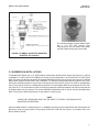
The Insertion Adapter mounts Model 399VP
into a 1-1/2 inch NPT process pipe.
Unscrewing the hex nut allows easy sensor
removal without twisting the sensor cable.
FIGURE 2-5. MODEL 399VP WITH INSERTION
ADAPTER (PN 23242-02)
2.5 SUBMERSION INSTALLATIONS.
The Model 399VP Sensor has a 1 in. MNPT process connection at the back of the sensor (see Figure 2-1). Utilizing
a standard 1 in. union (such as PN 9330022), the sensor may be mounted to a 1 in. SCH 80 CPVC or PVDF standpipe. The sensor can also be mounted in the Handrail Mounting Assembly (PN 11275-01; see Figure 2-6). Tapered
pipe threads in plastic tend to loosen after installation. It is therefore recommended that the tightness of the connection be checked frequently to ensure that no loosening has occurred. To prevent rain water or condensation
from running into the sensor, a weatherproof junction box is recommended (Rosemount Analytical PN 22719-02;
see Figure 2-8). The sensor cable must be run through a protective conduit for isolation from electrical interference
or physical abuse from the process. The sensor should be installed within 80° of vertical, with the electrode facing
down. The sensor's cable should not be run with power or control wiring.
NOTE
LARGE PIPE WRENCHES MUST NOT BE USED TO TIGHTEN THE SENSOR INTO
MOUNTING ACCESSORIES.
When the Model 399VP is installed using a 1 in. standpipe, the sensor can be cleaned while still submersed in the
process by using a jet spray cleaner. The jet spray cleaner (PN 12707-00; see Figure 2-7) can spray water or air
directly onto the sensor.
7
MODEL 399VP pH/ORP SENSOR
SECTION 2.0
INSTALLATION
HANDRAIL MOUNTING KIT (PN 1000857)
The Handrail Mounting Kit does not include
a pull box, pipe, or coupling. Sensor and
junction box are sold separately.
FIGURE 2-6. SENSOR SHOWN IN HANDRAIL MOUNTING ASSEMBLY (PN 11275-01)
The Handrail Mounting Assembly can be used in applications where Model 399VP needs to be placed in a pond, tank, aeration basin, or open channel. Handrail Mounting Assembly includes all parts seen in drawing; sensor is sold separately.
8
MODEL 399VP pH/ORP SENSOR
SECTION 2.0
INSTALLATION
FIGURE 2-7. JET SPRAY CLEANER (PN 12707-00)
USED WITH MODEL 399VP
The Pipe Mount Union Accessory (PN
9330022) is ideal for connecting Model
399VP to a pipe for insertion into a pond,
tank, aeration basin, or open channel.
The Jet Spray Cleaner eliminates routine
manual sensor maintenance by cleaning
Model 399VP with water or compressed air.
Flow through the cleaner can be controlled
by a solenoid valve. (Model 399 with integral
cable shown)
FIGURE 2-8. JUNCTION BOX (PN 22719-02) AND
PIPE MOUNT UNION ACCESSORY (PN 9330022)
9
MODEL 399VP pH/ORP SENSOR
SECTION 3.0
WIRING
SECTION 3.0.
WIRING
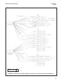
Figures 3-2 thru 3-23 provide the diagrams for wiring
the 399VP sensor to various analyzer/transmitters.
1. If the cable needs to be extended, use a high quality cable available from Rosemount Analytical. Refer
to Figures 3-2 through 3-23 for the appropriate junction box part number and the corresponding wiring
details.
NOTE
NOTE
When extending the mV signal from the sensor
through a remote junction box to the analyzer,
the outer braid of the extension cable to the
instrument must be terminated at earth ground
or by using an appropriate metal cable gland
fitting that provides a secure connection to the
instrument cable.
The Model 399VP is used with a Variopol coax cable.
The cable should be handled carefully and kept dry and
free of corrosive chemicals at all times. Extreme care
should be used to prevent it from being twisted, damaged or scraped by rough, sharp edges or surfaces.
If the extension cable is too long, either loop up
the excess cable or cut and terminate each
conductor neatly. Make sure that the overall
(outermost) drain wire is not shorted out
with either of the two inner drain wires
(shields).
2. Signal cable should be run in a dedicated conduit
(preferably an earth grounded metallic conduit)
and should be kept away from AC power lines.
DANGER
DO NOT CONNECT SENSOR CABLE TO
POWER LINES. SERIOUS INJURY MAY
RESULT.
TABLE 3-1. Remote Junction Box and Extension Cable Part Numbers
Model
Remote Junction
Box PN
Extension
Cable PN
54
23555-00
9200273*
81
23555-00
9200273*
1003/1023
23309-03
9200000
1050/1060
23309-03
9200000
1054
23309-04
9200273*
1054A/B
23309-04
9200273*
1055
23555-00
9200273*
1181
23309-03
9200273*
2054
23309-04
9200273*
2081
23309-04
9200273*
3081/4081
23555-00
9200273*
SCL
—
—
2700
—
—
* Note that PN 9200273 is a raw cable. It can also be purchased with
wires already prepared (PN 23646-01) for quicker installation.
10
MODEL 399VP pH/ORP SENSOR
SECTION 3.0
WIRING
MODEL 399VP
FIGURE 3-1. Wire and Connector Pin Functions
FIGURE 3-2. Model 81 Wiring
FIGURE 3-3. Model 1181 Wiring
FIGURE 3-4. Model 54 Wiring through Remote Junction Box
11
MODEL 399VP pH/ORP SENSOR
FIGURE 3-5. Model 54 Wiring
FIGURE 3-7. Model 1181, 1050/1060, and
1003/1023 Wiring through Remote Junction Box
12
SECTION 3.0
WIRING
FIGURE 3-6. Model 2081 Wiring
FIGURE 3-8. Model 2081 Wiring through
Remote Junction Box
MODEL 399VP pH/ORP SENSOR
FIGURE 3-9. Model 81 Wiring through
Remote Junction Box
SECTION 3.0
WIRING
FIGURE 3-10. Model 3081 & 4081 Wiring through
Remote Junction Box
FIGURE 3-11. Model 1055-22-32 Wiring
FIGURE 3-12. Model 3081 & 4081 Wiring
13
MODEL 399VP pH/ORP SENSOR
14
SECTION 3.0
WIRING
FIGURE 3-13. Model 1054 Wiring
FIGURE 3-14. Model 1054A/B and 2054 Wiring
FIGURE 3-15. Model 1054 Wiring through
a Remote Junction Box
FIGURE 3-16. Model 1054A/B & 2054 Wiring
through a Remote Junction Box
MODEL 399VP pH/ORP SENSOR
SECTION 3.0
WIRING
FIGURE 3-17. Model SCL-(P/Q) Wiring
FIGURE 3-18. Model 2700 Wiring
FIGURE 3-19. Model 54epH Wiring
FIGURE 3-20. Model 1055-22-32 Wiring through Remote Junction Boxes
15
MODEL 399VP pH/ORP SENSOR
DWG. NO.
41055107
SECTION 3.0
WIRING
REV.
C
FIGURE 3-21. Wiring Model 399VP-09, 400, 401, 402, 403, and 404 to Model 1055 (Pipe/Wall Mount).
16
MODEL 399VP pH/ORP SENSOR
DWG. NO.
41055108
SECTION 3.0
WIRING
REV.
C
FIGURE 3-22. Wiring Model 399VP-09, 400, 401, 402, 403, and 404 to Model 1055 (Panel Mount).
17
MODEL 399VP pH/ORP SENSOR
SECTION 3.0
WIRING
FIGURE 3-23. Preparation of Extension Cable (PN 9200273)
This cable is shipped as a raw cable. Cable must be prepared, as shown above, before installation. To avoid preparing
raw cable, PN 23646-01 can be used. PN 23646-01 cable offers the wires already prepared for installation.
18
MODEL 399VP pH/ORP SENSOR
SECTION 4.0
START-UP AND CALIBRATION
SECTION 4.0.
START-UP AND CALIBRATION
4.1
4.2
4.3
SENSOR PREPARATION
pH CALIBRATION
ORP CALIBRATION
4.1 SENSOR PREPARATION
Shake down the sensor to remove any air bubbles that may be present in the tip of the pH glass bulb. In most
cases, the pH sensor can simply be installed as shipped, and readings with an accuracy of ± 0.6 pH may be
obtained. To obtain greater accuracy or to verify proper operation, the sensor must be calibrated together with its
compatible analyzer or transmitter.
4.2 pH CALIBRATION
After a temporary connection is established between the sensor and the instrument, a buffer calibration may be
performed. Consult the appropriate pH/ORP analyzer or transmitter instruction manual for specific calibration and
standardization procedures, or see below for recommended two-point buffer calibration procedure.
Recommended two-point buffer calibration procedure:
Select two stable buffer solutions, preferably pH 4.0 and 10.0 (pH buffers other than pH 4.0 and pH 10.0 can be
used as long as the pH values are at least two pH units apart).
NOTE
A pH 7.0 buffer solution reads a mV value of approximately zero, and pH buffers read approximately
59.1 mV for each pH unit above or below pH 7.0. Check the pH buffer manufacturer specifications for millivolt values at various temperatures, since it may affect the actual value of the buffer solution mV/pH
value.
1. Immerse the sensor in the first buffer solution. Allow the sensor to adjust to the buffer temperature (to avoid
errors due to temperature differences between the buffer solution and sensor temperature) and wait for the
reading to stabilize. The value of the buffer can now be acknowledged by the analyzer/transmitter.
2. Once the first buffer has been acknowledged by the analyzer/transmitter, rinse the buffer solution off of the
sensor with distilled or deionized water and/or a small quantitiy of the next buffer solution.
3. Repeat steps 1 and 2 using the second buffer solution.
4. Once the analyzer/transmitter has acknowledged both buffer solutions, a sensor slope (mV/pH) is established
(the slope value can be found within the analyzer/transmitter).
5. The slope value should read about 59.1 mV/pH for a new sensor and will decrease over time to approximately 47-49 mV/pH. Once the slope reads below the 47-49 mV/pH range, either clean the sensor and recalibrate
for a better slope or install a new sensor to maintain accurate readings.
Recommended pH Sensor Standardization:
For maximum accuracy, the sensor can be standardized online or with a process grab sample after a buffer calibration has been performed and the sensor has been conditioned to the process. Standardization accounts for
the sensor junction potential and other interferences. Standardization will not change the sensor's slope but will
simply adjust the analyzer's reading to match that of the known process pH.
1. While obtaining a process solution sample (it is recommended that the sample be taken close to the sensor),
record the pH value that is shown on the analyzer/transmitter display.
2. Measure and record the pH of the process solution sample with another temperature compensated, calibrated pH instrument. For best results, standardization should be performed at the process temperature.
3. Adjust the analyzer/transmitter value to the standardized value.
19
MODEL 399VP pH/ORP SENSOR
SECTION 4.0
START-UP AND CALIBRATION
4.3 ORP CALIBRATION
Most industrial applications have a number of ORP reactions occurring in sequence or simultaneously. There can
be several components that are oxidized or reduced by the reagents that are used. Theoretically, the ORP potential is absolute because it is the result of the oxidation-reduction equilibrium. However, the actual measured potential is dependent on many factors, including the condition of the surface of the ORP platinum electrode. Therefore,
the sensor should be allowed 1-2 hours to become "conditioned" to the stream when first set up or after being
cleaned.
CAUTION
The solution used during the following check is an acid and should be handled with care. Follow the directions of the acid manufacturer. Wear the proper protective equipment. Do not let the solution come in contact with skin or clothing. If contact with skin is made, immediately rinse with clean water.
1. Make a temporary electrical connection between the sensor and the instrument.
2. Obtain an ORP standard solution (PN R508-16OZ). A standard solution can also be made quite simply by
adding a few crystals of quinhydrone to either pH 4 or pH 7 buffer. Quinhydrone is only slightly soluble therefore a few crystals will be required.
3. Immerse the sensor in the standard solution. Allow 1-2 minutes for the ORP sensor to stabilize.
4. Adjust the standardize control of the instrument to the solution value shown on the label of the PN R508-16OZ
standard solution or, if using a quinhydrone solution, in Table 4-1. The resulting potentials, measured with a
clean platinum electrode and saturated KCl/AgCl reference electrode, should be within ±20 millivolts of the
value. Solution temperature must be noted to ensure accurate interpretation of results. The ORP value of saturated quinhydrone solution is not stable over long periods of time. Therefore, these standards should be
made fresh each time they are used.
5. Remove the sensor from the buffer, rinse, and install in the process.
TABLE 4-1. ORP of Saturated Quinhydrone Solution (In Millivolts)
Temp °C
Millivolt Potential
20
pH 4 Solution
pH 7 Solution
20
30
20
25
30
264 260
94
87
80
268
25
MODEL 399VP pH/ORP SENSOR
SECTION 5.0
MAINTENANCE
SECTION 5.0.
MAINTENANCE
5.1
5.2
5.3
5.4
5.1
GENERAL
AUTOMATIC TEMPERATURE COMPENSATOR
pH ELECTRODE CLEANING
ORP PLATINUM ELECTRODE CHECK
GENERAL
The Model 399VP sensor is a disposable type sensor and therefore requires minimum maintenance. The sensor
should be kept clean and free of debris and sediment at all times. The frequency of cleaning, by wiping or brushing with a soft cloth or brush, is determined by the nature of the solution being measured. The sensor should be
removed from the process periodically and checked in buffer solutions.
WARNING
BEFORE REMOVING THE SENSOR, be absolutely certain that the process pressure is reduced to 0 psig and
the process temperature is lowered to a safe level!
If the sensor will not calibrate, refer to your analyzer/ transmitter instruction manual for proper test procedures. If
it is then determined that the sensor has failed, it should be discarded and replaced.
5.2
AUTOMATIC TEMPERATURE COMPENSATOR
The temperature compensator element is temperature sensitive and can be checked with an ohmmeter.
Resistance increases with temperature.
Resistance varies with temperature for a 3K and Pt100 element and can be determined according to Table 5-2 or
with the following formula:
RT = Ro [l+R1 (T-20)]
Where RT = Resistance
T = Temperature in °C
TABLE 5-2. TEMPERATURE vs RESISTANCE
OF AUTO T.C. ELEMENTS
Refer to Table 5-1 for Ro and R1 values
TABLE 5-1. Ro and R1 VALUES FOR
TEMPERATURE COMPENSATION ELEMENTS
Temperature
Compensation Element
3K
Pt100
Ro
R1
2934
107.7
.0045
.00385
Temperature °C
0
10
20
25
30
40
50
60
70
80
90
100
Resistance
(Ohms) ±1%
3K
Pt100
2670
100.0
2802
103.9
2934
107.8
3000
109.7
3066
111.7
3198
115.5
3330
119.4
3462
123.2
3594
127.1
3726
130.9
3858
134.7
3990
138.5
21
MODEL 399VP pH/ORP SENSOR
5.3
SECTION 5.0
MAINTENANCE
pH ELECTRODE CLEANING
If the electrode is coated or dirty, clean as follows:
1.
Remove the sensor from process.
2.
Wipe the glass bulb with a soft, clean, lint free cloth or tissue. If this does not remove the dirt or coating, go
to Step 3 (detergents clean oil and grease; acids remove scale).
3.
Wash the glass bulb in a mild detergent solution and rinse it in clean water. If this does not clean the glass
bulb, go to Step 4.
CAUTION
The solution used during the following check is an acid and should be handled with care. Follow the directions of the acid manufacturer. Wear the proper protective equipment. Do not let the solution come in contact with skin or clothing. If contact with skin is made, immediately rinse with clean water.
4.
Wash the glass bulb in a dilute 5% hydrochloric acid solution and rinse with clean water. Soaking the sensor
overnight in the acid solution can improve cleaning action.
NOTE
Erroneous pH results may result immediately after acid soak, due to reference junction potential build-up.
Replace the sensor if cleaning does not restore sensor operation.
5.4 ORP PLATINUM ELECTRODE CHECK
The platinum electrode may be checked as follows: there are two types of standard solutions that may be used to
check the ORP electrode/transmitter system.
Type 1: A prepared ORP standard solution (Ferrous/ferric ammonia sulfate standard PN R508-16OZ)
OR
An ORP standard solution can be prepared from the following formula: Dissolve 39.2 grams of reagent
grade ferrous ammonium sulfate, Fe(NH4)2 (SO4)2 • 6H2O and 48.2 grams of reagent grade ferric ammonium sulfate, FeNH4(SO4)2 • 12H2O, in approximately 700 milliliters of water (distilled water is preferred,
but tap water is acceptable). Slowly and carefully add 56.2 milliliters of concentrated sulfuric acid. Add sufficient water to bring the total solution volume up to 1000 ml. This standard ORP solution, although not as
simple to prepare as the quinhydrone formula, is much more stable and will maintain its millivolt value for
approximately one year when stored in glass containers. This solution (ferric/ferrous ammonium sulfate)
will produce a nominal ORP of 476 +20 mV at 25°C when used with a saturated KCl/AgCl reference electrode and platinum measuring electrode. Some tolerance in mV values is to be expected due to the rather
large liquid reference junction potentials that can arise when measuring this strongly acidic and concentrated solution. However, if the measuring electrodes are kept clean and in good operating condition, consistently repeatable calibrations can be carried out using this standard solution.
Type 2: Another type of commonly used ORP standard solution is the saturated quinhydrone solution. Refer to
Section 4.3.
CAUTION
The solution used during the following check is an acid and should be handled with care. Follow the
directions of the acid manufacturer. Wear the proper protective equipment. If contact with skin or clothing is made, immediately rinse with plenty of clean water.
Cleaning a Platinum Electrode. The electrode can be restored to normal operation by simply cleaning the platinum
electrode with baking soda. Polish it by rubbing it with a damp paper towel and baking soda until a bright, shiny appearance is attained.
22
MODEL 399VP pH/ORP SENSOR
SECTION 6.0
TROUBLESHOOTING
SECTION 6.0.
TROUBLESHOOTING
TROUBLESHOOTING. The table below lists common problems, causes and remedies typically encountered in
process measurement.
Problem
Probable Cause
Remedy
Meter reads off scale (display
reads overrange).
T.C. element shorted.
Check T.C. element as instructed
in Section 5.2 and replace
sensor if defective.
Sensor not in process. Sample
stream is low or air bubbles are
present.
Make sure sensor is in process with
sufficient sample stream (refer to
Section 2.0 for installation details).
Open glass electrode.
Replace sensor.
Reference element open - no contact.
Replace sensor.
Display reads between 3 and 6 pH,
regardless of actual pH of solution
or sample.
Electrode cracked.
Replace sensor.
Meter or display indication swings
or jumps widely in AUTO T.C. Mode.
T.C. element shorted.
Check T.C. element as instructed
in Section 5.2 and replace
sensor if defective.
Span between buffers extremely
short in AUTO T.C. Mode.
T.C. element open.
Check T.C. element as instructed
in Section 5.2 and replace sensor
if defective.
Sluggish or slow meter indication
for real changes in pH level.
Electrode coated.
Clean sensor as instructed in
Section 5.3. Replace sensor if
cracked.
Electrode defective.
Replace sensor.
Transmitter cannot be standardized.
Electrode coated or cracked.
Clean sensor as instructed in
Section 5.3. Replace sensor if
cracked.
Transmitter short spans between
two different buffer values.
Aged glass electrode or high
temperature exposure.
Replace sensor.
Electrode coated .
Clean sensor as instructed in
Section 5.3. Replace sensor if
cracked.
23
MODEL 399VP pH/ORP SENSOR
SECTION 7.0
RETURN OF MATERIAL
SECTION 7.0
RETURN OF MATERIAL
7.1 GENERAL.
To expedite the repair and return of instruments, proper communication between the customer and the factory is
important. Before returning a product for repair, call 1-949-757-8500 for a Return Materials Authorization (RMA)
number.
7.2 WARRANTY REPAIR.
The following is the procedure for returning instruments still under warranty:
1.
Call Rosemount Analytical for authorization.
2.
To verify warranty, supply the factory sales order number or the original purchase order number. In the case
of individual parts or sub-assemblies, the serial number on the unit must be supplied.
3.
Carefully package the materials and enclose your “Letter of Transmittal” (see Warranty). If possible, pack the
materials in the same manner as they were received.
4.
Send the package prepaid to:
Rosemount Analytical Inc., Uniloc Division
Uniloc Division
2400 Barranca Parkway
Irvine, CA 92606
Attn: Factory Repair
RMA No. ____________
Mark the package: Returned for Repair
Model No. ____
7.3 NON-WARRANTY REPAIR.
The following is the procedure for returning for repair instruments that are no longer under warranty:
1.
Call Rosemount Analytical for authorization.
2.
Supply the purchase order number, and make sure to provide the name and telephone number of the individual to be contacted should additional information be needed.
3.
Do Steps 3 and 4 of Section 7.2.
NOTE
Consult the factory for additional information regarding service or repair.
24
RETURN OF MATERIALS REQUEST
C
U
S
T
O
M
E
R
N
O
T
I
C
E
T
O
FROM:
•IMPORTANT!
This form must be completed to ensure expedient factory service.
RETURN
BILL TO:
_____________________________
_____________________________
_____________________________
_____________________________
_____________________________
_____________________________
_____________________________
_____________________________
_____________________________
S
E
N
D
E
R
CUSTOMER/USER MUST SUBMIT MATERIAL SAFETY SHEET (MSDS) OR COMPLETE STREAM COMPOSITION, AND/OR
LETTER CERTIFYING THE MATERIALS HAVE BEEN DISINFECTED AND/OR DETOXIFIED WHEN RETURNING ANY PRODUCT, SAMPLE OR MATERIAL THAT HAVE BEEN EXPOSED TO OR USED IN AN ENVIRONMENT OR PROCESS THAT CONTAINS A HAZARDOUS MATERIAL ANY OF THE ABOVE THAT IS SUBMITTED TO ROSEMOUNT ANALYTICAL WITHOUT
THE MSDS WILL BE RETURNED TO SENDER C.O.D. FOR THE SAFETY AND HEALTH OF OUR EMPLOYEES. WE THANK
YOU IN ADVANCE FOR COMPLIANCE TO THIS SUBJECT.
SENSOR OR CIRCUIT BOARD ONLY:
(Please reference where from in MODEL / SER. NO. Column)
1. PART NO.__________________________1. MODEL_________________________________1.
SER. NO. ________________
2. PART NO.__________________________2. MODEL_________________________________2.
SER. NO. ________________
3. PART NO.__________________________3. MODEL_________________________________3.
SER. NO. ________________
4. PART NO.__________________________4. MODEL_________________________________4.
SER. NO. ________________
R
E
A
S
O
N
PLEASE CHECK ONE:
F
O
R
REPLACEMENT REQUIRED? YES NO
R
E
T
U
R
N
REPAIR AND CALIBRATE
DEMO EQUIPMENT NO. __________________________
EVALUATION
OTHER (EXPLAIN) _______________________________
_________________________________________________
DESCRIPTION OF MALFUNCTION:
______________________________________________________________________________________________________
______________________________________________________________________________________________________
______________________________________________________________________________________________________
R
E
P
A
I
R
S
T
A
T
U
S
WARRANTY REPAIR REQUESTED:
YES-REFERENCE ORIGINAL ROSEMOUNT ANALYTICAL ORDER NO. ________________________________________
CUSTOMER PURCHASE ORDER NO. _________________________________________________
NO-PROCEED WITH REPAIRS-INVOICE AGAINST P.O. NO. _________________________________________________
NO-CONTACT WITH ESTIMATE OF REPAIR CHARGES: LETTER __________________________________________
PHONE ___________________________________________
NAME ____________________________________________________
PHONE _________________________________________
ADDRESS ___________________________________________________________________________________________________
______________________________________________________________
ZIP _________________________________________
RETURN AUTHORITY FOR CREDIT ADJUSTMENT [Please check appropriate box(s)]
WRONG PART RECEIVED
REPLACEMENT RECEIVED
DUPLICATE SHIPMENT
REFERENCE ROSEMOUNT ANALYTICAL SALES ORDER NO.__________
RETURN FOR CREDIT
RETURN AUTHORIZED BY: ______________________________________
WARRANTY DEFECT____________________________________________________________________________________
_____________________________________________________________________________________________________
24-6047
Emerson Process Management
Rosemount Analytical Inc.
2400 Barranca Parkway
Irvine, CA 92606 USA
Tel: (949) 757-8500
Fax: (949) 474-7250
http://www.raihome.com
© Rosemount Analytical Inc. 2005
The right people, the right answers, right now.
Immediate, Reliable Analytical Support
Now there’s a way to quickly get the right answers for your liquid analytical instrumentation questions: the Analytical Customer Support Center.
Our staff of trained professionals is ready to provide the information you need. If you are placing an
order, verifying delivery, requesting application information, or just want to contact a Rosemount
Analytical representative, a call to the Customer Support Center will provide you with the right people, the right answers, right now.
A Worldwide Network of Sales and Service
Emerson Process Management’s field sales offices are your source for more information on the fill line of Rosemount Analytical
products. Field sales personnel will work closely with you to supply technical data and application information.
For more information, please contact your nearest Emerson Process Management sales office.
THE AMERICAS HEADQUARTERS
Rosemount Analytical Inc.
Liquid Division
2400 Barranca Parkway
Irvine, CA 92606
Phone: 949-757-8500
Toll Free: 800-854-8257
Fax: 949-474-7250
ASIA-PACIFIC
Fisher-Rosemount
Singapore Private Ltd.
1 Pandan Crescent
Singapore 0512
Republic of Singapore
Phone: 65-777-8211
Fax: 65-777-0947
EUROPE, MIDDLE EAST, AND
AFRICA
Fisher-Rosemount Ltd.
Heath Place
Bognor Regis
West Sussex PO22 9SH
England
Phone: 44-1243-863121
Fax: 44-1243-845354
VISIT OUR WEBSITE AT
www.raihome.com
ADDITIONAL SALES OFFICES IN:
Argentina
Australia
Austria
Azerbajan
Bahrain
Belgium
Bolivia
Brazil
Brunei
Bulgaria
Canada
Chile
China
Colombia
Costa Rica
Croatia
Czech Republic
Denmark
Egypt
Ecuador
Finland
France
Germany
Greece
Hong Kong
Hungary
India
Indonesia
Ireland
Israel
Italy
Jamaica
Japan
Jordan
Kazakhstan
Korea
Kuwait
Malaysia
Mexico
Netherlands
New Zealand
Nigeria
Norway
Oman
Pakistan
Paraguay
Peru
Philippines
Poland
Portugal
Puerto Rico
Qatar
Romania
Russia
Saudi Arabia
Singapore
Slovak Republic
South Africa
Spain
Sweden
Switzerland
Syria
Taiwan
Thailand
Tobago
Trinidad
Tunisia
Turkey
Ukraine
United Arab
Emirates
United Kingdom
Uruguay
Uzbekistan
Venezuela
Yemen
WARRANTY
Seller warrants that the firmware will execute the programming instructions provided by Seller, and that the Goods manufactured
or Services provided by Seller will be free from defects in materials or workmanship under normal use and care until the expiration of the applicable warranty period. Goods are warranted for twelve (12) months from the date of initial installation or eighteen
(18) months from the date of shipment by Seller, whichever period expires first. Consumables, such as glass electrodes,
membranes, liquid junctions, electrolyte, o-rings, catalytic beads, etc., and Services are warranted for a period of 90
days from the date of shipment or provision.
Products purchased by Seller from a third party for resale to Buyer ("Resale Products") shall carry only the warranty extended by
the original manufacturer. Buyer agrees that Seller has no liability for Resale Products beyond making a reasonable commercial
effort to arrange for procurement and shipping of the Resale Products.
If Buyer discovers any warranty defects and notifies Seller thereof in writing during the applicable warranty period, Seller shall, at
its option, promptly correct any errors that are found by Seller in the firmware or Services, or repair or replace F.O.B. point of manufacture that portion of the Goods or firmware found by Seller to be defective, or refund the purchase price of the defective portion of the Goods/Services.
All replacements or repairs necessitated by inadequate maintenance, normal wear and usage, unsuitable power sources, unsuitable environmental conditions, accident, misuse, improper installation, modification, repair, storage or handling, or any other
cause not the fault of Seller are not covered by this limited warranty, and shall be at Buyer's expense. Seller shall not be obligated to pay any costs or charges incurred by Buyer or any other party except as may be agreed upon in writing in advance by
an authorized Seller representative. All costs of dismantling, reinstallation and freight and the time and expenses of Seller's personnel for site travel and diagnosis under this warranty clause shall be borne by Buyer unless accepted in writing by Seller.
Goods repaired and parts replaced during the warranty period shall be in warranty for the remainder of the original warranty period or ninety (90) days, whichever is longer. This limited warranty is the only warranty made by Seller and can be amended only
in a writing signed by an authorized representative of Seller. Except as otherwise expressly provided in the Agreement, THERE
ARE NO REPRESENTATIONS OR WARRANTIES OF ANY KIND, EXPRESS OR IMPLIED, AS TO MERCHANTABILITY, FITNESS FOR PARTICULAR PURPOSE, OR ANY OTHER MATTER WITH RESPECT TO ANY OF THE GOODS OR SERVICES.
RETURN OF MATERIAL
Material returned for repair, whether in or out of warranty, should be shipped prepaid to:
Emerson Process Management
Liquid Division
2400 Barranca Parkway
Irvine, CA 92606
The shipping container should be marked:
Return for Repair
Model _______________________________
The returned material should be accompanied by a letter of transmittal which should include the following information (make a
copy of the "Return of Materials Request" found on the last page of the Manual and provide the following thereon):
1.
2.
3.
4.
5.
Location type of service, and length of time of service of the device.
Description of the faulty operation of the device and the circumstances of the failure.
Name and telephone number of the person to contact if there are questions about the returned material.
Statement as to whether warranty or non-warranty service is requested.
Complete shipping instructions for return of the material.
Adherence to these procedures will expedite handling of the returned material and will prevent unnecessary additional charges
for inspection and testing to determine the problem with the device.
If the material is returned for out-of-warranty repairs, a purchase order for repairs should be enclosed.
The right people,
the right answers,
right now.
ON-LINE ORDERING NOW AVAILABLE ON OUR WEB SITE
http://www.raihome.com
Specifications subject to change without notice.
Credit Cards for U.S. Purchases Only.
Emerson Process Management
Liquid Division
2400 Barranca Parkway
Irvine, CA 92606 USA
Tel: (949) 757-8500
Fax: (949) 474-7250
http://www.raihome.com
© Rosemount Analytical Inc. 2005