1
System Configuration Manual
300510EN, Rev AA
December 2010
Raptor
Tank Gauging System
www.rosemount-tg.com
System Configuration Manual
300510EN, Rev AA
December 2010
Rosemount Raptor
Rosemount Raptor
Configuration with Rosemount
TankMaster WinSetup
NOTICE
Read this manual before working with the product. For personal and system safety, and for
optimum product performance, make sure you thoroughly understand the contents before
installing, using, or maintaining this product.
For equipment service or support needs, contact your local Emerson Process
Management/Rosemount Tank Gauging representative.
Version
This manual is based on the functionality of TankMaster WinSetup version 6.x.
For older TankMaster versions all functionality described in this manual may not be
available and the Graphical User Interface (GUI) may look different.
Cover Photo: system_config_front.tif
www.rosemount-tg.com
System Configuration Manual
300510EN, Rev AA
December 2010
Rosemount Raptor
Table of Contents
SECTION 1
Introduction
1.1
1.2
Manual Overview. . . . . . . . . . . . . . . . . . . . . . . . . . . . . . . . . . . . . . 1-1
Technical Documentation . . . . . . . . . . . . . . . . . . . . . . . . . . . . . . . 1-2
3.1
3.2
3.3
What is TankMaster?. . . . . . . . . . . . . . . . . . . . . . . . . . . . . . . . . . . 3-1
TankMaster Software Package . . . . . . . . . . . . . . . . . . . . . . . . . . . 3-2
Installing the TankMaster Software . . . . . . . . . . . . . . . . . . . . . . . . 3-4
3.3.1 System Requirements . . . . . . . . . . . . . . . . . . . . . . . . . . . 3-4
3.3.2 Installed Software Modules . . . . . . . . . . . . . . . . . . . . . . . 3-4
3.3.3 Installation Procedure. . . . . . . . . . . . . . . . . . . . . . . . . . . . 3-5
Installing a Tank Level Gauging System . . . . . . . . . . . . . . . . . . . . 3-6
Illegal characters . . . . . . . . . . . . . . . . . . . . . . . . . . . . . . . . . . . . . . 3-6
SECTION 2
Raptor System Overview
SECTION 3
Using TankMaster
3.4
3.5
SECTION 4
The WinSetup Main
Window
4.1
4.2
4.3
4.4
4.5
SECTION 5
Installing a Raptor Level
Gauging System
5.1
5.2
www.rosemount-tg.com
Menus . . . . . . . . . . . . . . . . . . . . . . . . . . . . . . . . . . . . . . . . . . . . . . 4-3
Toolbar . . . . . . . . . . . . . . . . . . . . . . . . . . . . . . . . . . . . . . . . . . . . . 4-4
Status bar . . . . . . . . . . . . . . . . . . . . . . . . . . . . . . . . . . . . . . . . . . . 4-5
Workspace - Viewing Tanks and Devices . . . . . . . . . . . . . . . . . . . 4-6
4.4.1 Workspace . . . . . . . . . . . . . . . . . . . . . . . . . . . . . . . . . . . . 4-7
4.4.2 Icons. . . . . . . . . . . . . . . . . . . . . . . . . . . . . . . . . . . . . . . . . 4-8
User Management . . . . . . . . . . . . . . . . . . . . . . . . . . . . . . . . . . . . . 4-9
4.5.1 Logging On to TankMaster. . . . . . . . . . . . . . . . . . . . . . . 4-10
4.5.2 To Administrate User Accounts . . . . . . . . . . . . . . . . . . . 4-11
4.5.3 To Set Required Access Levels . . . . . . . . . . . . . . . . . . . 4-13
4.5.4 To Change Protection Level of Separate Windows . . . . 4-14
4.5.5 To Change Password. . . . . . . . . . . . . . . . . . . . . . . . . . . 4-15
4.5.6 To Change Inactivity Timeout. . . . . . . . . . . . . . . . . . . . . 4-16
System Configuration Overview . . . . . . . . . . . . . . . . . . . . . . . . . . 5-2
5.1.1 Preparations . . . . . . . . . . . . . . . . . . . . . . . . . . . . . . . . . . . 5-2
5.1.2 Installation Procedure. . . . . . . . . . . . . . . . . . . . . . . . . . . . 5-2
5.1.3 Using the Device Installation Wizard . . . . . . . . . . . . . . . . 5-5
Communication Protocol Setup . . . . . . . . . . . . . . . . . . . . . . . . . . . 5-6
5.2.1 Master Protocol Channel Configuration . . . . . . . . . . . . . . 5-7
5.2.2 Slave Protocol Channel Configuration . . . . . . . . . . . . . . 5-10
5.2.3 Log File Configuration . . . . . . . . . . . . . . . . . . . . . . . . . . 5-14
5.2.4 Changing the current Protocol Channel Configuration. . 5-14
5.2.5 Protocol Server Configuration . . . . . . . . . . . . . . . . . . . . 5-15
System Configuration Manual
300510EN, Rev AA
December 2010
Rosemount Raptor
5.3
5.4
5.5
5.6
5.7
5.8
5.9
5.10
5.11
5.12
5.13
5.14
5.15
5.16
TOC-2
Preferences . . . . . . . . . . . . . . . . . . . . . . . . . . . . . . . . . . . . . . . . . 5-16
5.3.1 Measurement Units . . . . . . . . . . . . . . . . . . . . . . . . . . . . 5-16
5.3.2 Ambient Air Temperature . . . . . . . . . . . . . . . . . . . . . . . . 5-17
5.3.3 Inventory. . . . . . . . . . . . . . . . . . . . . . . . . . . . . . . . . . . . . 5-18
5.3.4 Miscellaneous. . . . . . . . . . . . . . . . . . . . . . . . . . . . . . . . . 5-19
5.3.5 Setting the Name Tag Prefixes . . . . . . . . . . . . . . . . . . . 5-20
5.3.6 Tank View Layout. . . . . . . . . . . . . . . . . . . . . . . . . . . . . . 5-21
5.3.7 Tank Visibility . . . . . . . . . . . . . . . . . . . . . . . . . . . . . . . . . 5-23
Field Device Installation - Overview . . . . . . . . . . . . . . . . . . . . . . 5-24
Installing a Rosemount 2160 FCU. . . . . . . . . . . . . . . . . . . . . . . . 5-25
5.5.1 Introduction. . . . . . . . . . . . . . . . . . . . . . . . . . . . . . . . . . . 5-25
5.5.2 Installation Procedure. . . . . . . . . . . . . . . . . . . . . . . . . . . 5-25
5.5.3 Examples of 2160 FCU Slave Database Configuration . 5-32
5.5.4 Summary of 2160 Installation and Configuration . . . . . . 5-37
Installing a Rosemount 2410 Tank Hub . . . . . . . . . . . . . . . . . . . 5-38
5.6.1 Installation Wizard . . . . . . . . . . . . . . . . . . . . . . . . . . . . . 5-38
5.6.2 Summary of Tank Hub Installation and Configuration . . 5-49
Installing a Rosemount 5900S Radar Level Gauge . . . . . . . . . . 5-51
5.7.1 Configuration via the Properties Window . . . . . . . . . . . . 5-52
5.7.2 Installing a 5900S Using the Installation Wizard . . . . . . 5-58
5.7.3 Advanced Configuration . . . . . . . . . . . . . . . . . . . . . . . . . 5-62
Installing Auxiliary Tank Devices . . . . . . . . . . . . . . . . . . . . . . . . . 5-65
5.8.1 Opening the Properties Window. . . . . . . . . . . . . . . . . . . 5-65
5.8.2 Communication Parameter Setup . . . . . . . . . . . . . . . . . 5-67
5.8.3 Temperature Sensor Configuration . . . . . . . . . . . . . . . . 5-68
5.8.4 Average Temperature Calculation . . . . . . . . . . . . . . . . . 5-70
5.8.5 Auxiliary Sensor Configuration . . . . . . . . . . . . . . . . . . . . 5-72
5.8.6 Advanced Parameter Source Configuration. . . . . . . . . . 5-74
5.8.7 2230 Graphical Field Display . . . . . . . . . . . . . . . . . . . . . 5-76
Installing a Rosemount 5400 . . . . . . . . . . . . . . . . . . . . . . . . . . . . 5-78
5.9.1 Configuration via 5400 Properties . . . . . . . . . . . . . . . . . 5-79
5.9.2 Installing a 5400 Using the Installation Wizard. . . . . . . . 5-84
5.9.3 Advanced Configuration . . . . . . . . . . . . . . . . . . . . . . . . . 5-88
Installing a Rosemount 5300 . . . . . . . . . . . . . . . . . . . . . . . . . . . . 5-90
5.10.1 Configuration via 5300 Properties . . . . . . . . . . . . . . . . . 5-91
5.10.2 Installing a 5300 Using the Installation Wizard. . . . . . . . 5-95
5.10.3 Advanced Configuration . . . . . . . . . . . . . . . . . . . . . . . . . 5-99
Installing a Tank . . . . . . . . . . . . . . . . . . . . . . . . . . . . . . . . . . . . 5-101
5.11.1 Overview . . . . . . . . . . . . . . . . . . . . . . . . . . . . . . . . . . . 5-101
5.11.2 Starting the Tank Installation Wizard . . . . . . . . . . . . . . 5-102
5.11.3 Installing a New Tank . . . . . . . . . . . . . . . . . . . . . . . . . . 5-103
5.11.4 Summary of Tank Installation and Configuration . . . . . 5-111
5.11.5 To Change Tank Configuration . . . . . . . . . . . . . . . . . . 5-112
5.11.6 To Uninstall a Tank . . . . . . . . . . . . . . . . . . . . . . . . . . . 5-113
Adding a Tank to a Raptor System . . . . . . . . . . . . . . . . . . . . . . 5-114
5.12.1 Adding a New Tank and a New 2410 Tank Hub . . . . . 5-115
5.12.2 Adding a New Tank to an Existing 2410 Tank Hub . . . 5-117
Level Gauge Calibration . . . . . . . . . . . . . . . . . . . . . . . . . . . . . . 5-122
5.13.1 Manual Adjustment. . . . . . . . . . . . . . . . . . . . . . . . . . . . 5-122
5.13.2 Using the Calibrate Function . . . . . . . . . . . . . . . . . . . . 5-123
Tank Capacity . . . . . . . . . . . . . . . . . . . . . . . . . . . . . . . . . . . . . . 5-124
Tank Entry . . . . . . . . . . . . . . . . . . . . . . . . . . . . . . . . . . . . . . . . . 5-125
Setting up a Hybrid System . . . . . . . . . . . . . . . . . . . . . . . . . . . . 5-126
Table of Contents
System Configuration Manual
300510EN, Rev AA
December 2010
Rosemount Raptor
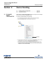
SECTION 6
Device Handling
6.1
6.2
To Change Device Configuration . . . . . . . . . . . . . . . . . . . . . . . . . 6-1
To Uninstall a Device. . . . . . . . . . . . . . . . . . . . . . . . . . . . . . . . . . . 6-3
SECTION 7
Service Functions
7.1
7.2
7.3
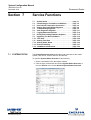
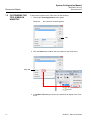
System Status . . . . . . . . . . . . . . . . . . . . . . . . . . . . . . . . . . . . . . . . 7-1
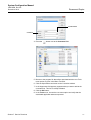
Customizing the Tools Menu in WinSetup. . . . . . . . . . . . . . . . . . . 7-2
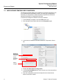
User Defined Temperature Conversion. . . . . . . . . . . . . . . . . . . . . 7-4
7.3.1 User Defined Linearization Table . . . . . . . . . . . . . . . . . . . 7-5
7.3.2 User Defined Formula . . . . . . . . . . . . . . . . . . . . . . . . . . . 7-6
7.3.3 User Defined Individual Formula . . . . . . . . . . . . . . . . . . . 7-7
Viewing Input and Holding Registers. . . . . . . . . . . . . . . . . . . . . . . 7-8
To Edit Holding Registers . . . . . . . . . . . . . . . . . . . . . . . . . . . . . . . 7-9
View Diagnostic Registers. . . . . . . . . . . . . . . . . . . . . . . . . . . . . . 7-11
7.6.1 The Configure Button . . . . . . . . . . . . . . . . . . . . . . . . . . . 7-12
7.6.2 Restore to Default Setting . . . . . . . . . . . . . . . . . . . . . . . 7-13
Logging Measurement Data . . . . . . . . . . . . . . . . . . . . . . . . . . . . 7-14
Saving and Loading Database Registers . . . . . . . . . . . . . . . . . . 7-15
7.8.1 To Save Device Registers Single Device. . . . . . . . . . . . 7-15
7.8.2 To Save Device Registers Multiple Devices. . . . . . . . . . 7-16
7.8.3 To Recover a Device Database . . . . . . . . . . . . . . . . . . . 7-17
Upgrading The Device Software . . . . . . . . . . . . . . . . . . . . . . . . . 7-18
Tank Scan . . . . . . . . . . . . . . . . . . . . . . . . . . . . . . . . . . . . . . . . . . 7-20
7.10.1 Graph Area. . . . . . . . . . . . . . . . . . . . . . . . . . . . . . . . . . . 7-22
7.10.2 Legend/Options . . . . . . . . . . . . . . . . . . . . . . . . . . . . . . . 7-23
7.10.3 File Storage . . . . . . . . . . . . . . . . . . . . . . . . . . . . . . . . . . 7-26
7.10.4 Action Buttons . . . . . . . . . . . . . . . . . . . . . . . . . . . . . . . . 7-30
7.10.5 Editing . . . . . . . . . . . . . . . . . . . . . . . . . . . . . . . . . . . . . . 7-31
Viewing Tank Data . . . . . . . . . . . . . . . . . . . . . . . . . . . . . . . . . . . 7-33
7.11.1 Viewing Data from All Tanks . . . . . . . . . . . . . . . . . . . . . 7-33
7.11.2 Viewing Data From a Single Tank . . . . . . . . . . . . . . . . . 7-34
Viewing Alarm Status . . . . . . . . . . . . . . . . . . . . . . . . . . . . . . . . . 7-35
Protocol Handling . . . . . . . . . . . . . . . . . . . . . . . . . . . . . . . . . . . . 7-37
7.13.1 Logging the Channel Communication . . . . . . . . . . . . . . 7-37
7.13.2 Saving the Communication Log to File. . . . . . . . . . . . . . 7-39
7.13.3 Searching for Connected Devices . . . . . . . . . . . . . . . . . 7-42
7.13.4 Channel Statistics. . . . . . . . . . . . . . . . . . . . . . . . . . . . . . 7-43
TankMaster Administrator . . . . . . . . . . . . . . . . . . . . . . . . . . . . . . 7-44
7.14.1 Log on . . . . . . . . . . . . . . . . . . . . . . . . . . . . . . . . . . . . . . 7-45
7.14.2 Changing the Administrator Program password. . . . . . . 7-46
7.14.3 Autostart . . . . . . . . . . . . . . . . . . . . . . . . . . . . . . . . . . . . . 7-47
7.14.4 Backup . . . . . . . . . . . . . . . . . . . . . . . . . . . . . . . . . . . . . . 7-48
7.14.5 Restore. . . . . . . . . . . . . . . . . . . . . . . . . . . . . . . . . . . . . . 7-50
7.14.6 File Version Information . . . . . . . . . . . . . . . . . . . . . . . . . 7-54
7.14.7 Processes. . . . . . . . . . . . . . . . . . . . . . . . . . . . . . . . . . . . 7-55
7.4
7.5
7.6
7.7
7.8
7.9
7.10
7.11
7.12
7.13
7.14
SECTION 8
Menu Guide
Table of Contents
8.1
8.2
8.3
8.4
8.5
File. . . . . . . . . . . . . . . . . . . . . . . . . . . . . . . . . . . . . . . . . . . . . . . . . 8-2
View. . . . . . . . . . . . . . . . . . . . . . . . . . . . . . . . . . . . . . . . . . . . . . . . 8-2
Service. . . . . . . . . . . . . . . . . . . . . . . . . . . . . . . . . . . . . . . . . . . . . . 8-3
Tools . . . . . . . . . . . . . . . . . . . . . . . . . . . . . . . . . . . . . . . . . . . . . . . 8-9
Help . . . . . . . . . . . . . . . . . . . . . . . . . . . . . . . . . . . . . . . . . . . . . . . . 8-9
TOC-3
System Configuration Manual
Rosemount Raptor
TOC-4
300510EN, Rev AA
December 2010
Table of Contents
System Configuration Manual
300510EN, Rev AA
December 2010
Section 1
Rosemount Raptor
Introduction
1.1
1.2
Manual Overview . . . . . . . . . . . . . . . . . . . . . . . . . . . page 1-1
Technical Documentation . . . . . . . . . . . . . . . . . . . . page 1-2
This manual describes the recommended installation procedure for setting up
a Rosemount Raptor system. It is based on using the TankMaster Winsetup
program as a configuration tool. The manual also provides information on the
basic functions of the TankMaster WinSetup configuration tool.
The Raptor System Configuration manual guides you through the process of
setting up a Raptor system with field devices and tanks for operation in
TankMaster.
The Rosemount Raptor product portfolio includes a wide range of
components for small and large customized tank gauging systems. The
system includes various field devices, such as radar level gauges,
temperature transmitters, and pressure transmitters for complete inventory
control. The TankMaster software suite provides you with the tools that you
need to configure and operate the Rosemount Raptor system.
1.1 MANUAL
OVERVIEW
The Raptor System Configuration manual includes the following sections:
Section 1: Introduction
A description of the various components in the Raptor system.
Section 2: Raptor System Overview
A description of the various components in the Raptor system.
Section 3: Using TankMaster
An introduction to the TankMaster software package.
Section 4: The WinSetup Main Window
An introduction to the basic features of the WinSetup configuration program. It
describes the workspace, menus, and various toolbars.
Section 5: Installing a Raptor Level Gauging System
A description of the recommended configuration procedure for a Rosemount
Raptor system.
Section 6: Device Handling
A short description of the basic functions for changing device configuration
and how to uninstall devices from the WinSetup workspace.
www.rosemount-tg.com
System Configuration Manual
300510EN, Rev AA
December 2010
Rosemount Raptor
Section 7: Service Functions
A description of various functions supported by TankMaster WinSetup for
service and maintenance of different Raptor field devices.
Section 8: Menu Guide
A guide to menus and menu options in the TankMaster WinSetup program.
1.2 TECHNICAL
DOCUMENTATION
1-2
The Raptor System includes the following documents:
•
Raptor Technical Description (704010EN)
•
Rosemount 5900S Reference Manual (300520EN)
•
Rosemount 2410 Reference Manual (300530EN)
•
Rosemount 2240S Reference Manual (300550EN)
•
Rosemount 2230 Reference Manual (300560EN)
•
Raptor System Configuration Manual (300510EN)
•
Rosemount 5300 Product Data Sheet (00813-0100-4530)
•
Rosemount 5400 Product Data Sheet (00813-0100-4026)
•
Rosemount 5300 Series Reference Manual (00809-0100-4530)
•
Rosemount 5400 Series Reference Manual (00809-0100-4026)
•
Rosemount TankMaster WinOpi Reference Manual (303028EN)
•
Rosemount Raptor Installation Drawings
Section 1. Introduction
System Configuration Manual
300510EN, Rev AA
December 2010
Section 2
Rosemount Raptor
Raptor System Overview
Raptor is a state-of-the art inventory and custody transfer radar tank level
gauging system. It is developed for a wide range of applications at refineries,
tank farms and fuel depots, and fulfills the highest requirements on
performance and safety.
The field devices on the tank communicate over the intrinsically safe Tankbus.
The Tankbus is based on a standardized fieldbus, the FISCO(1) FOUNDATION™
fieldbus, and allows integration of any device supporting that protocol. By
utilizing a bus powered 2-wire intrinsically safe fieldbus the power
consumption is minimized. The standardized fieldbus also enables integration
of other vendors’ equipment on the tank.
The Raptor product portfolio includes a wide range of components to build
small or large customized tank gauging systems. The system includes various
devices, such as radar level gauges, temperature transmitters, and pressure
transmitters for complete inventory control. Such systems are easily
expanded thanks to the modular design.
Raptor is a versatile system that is compatible with and can emulate all major
tank gauging systems. Moreover, the well-proven emulation capability
enables step-by-step modernization of a tank farm, from level gauges to
control room solutions.
It is possible to replace old mechanical or servo gauges with modern Raptor
gauges, without replacing the control system or field cabling. It is further
possible to replace old HMI/SCADA-systems and field communication
devices without replacing the old gauges.
There is a distributed intelligence in the various system units which
continuously collect and process measurement data and status information.
When a request for information is received an immediate response is sent
with updated information.
The flexible Raptor system supports several combinations to achieve
redundancy, from control room to the different field devices. Redundant
network configuration can be achieved at all levels by doubling each unit and
using multiple control room work stations.
(1)
www.rosemount-tg.com
See documents IEC 61158-2 and IEC/TS 60079-27
System Configuration Manual
300510EN, Rev AA
December 2010
Rosemount Raptor
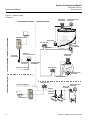
Figure 2-1. Raptor system
architecture
OPERATIONAL CONTROL
CUSTODY TRANSFER / INVENTORY TANK GAUGING
NON-HAZARDOUS AREA
5900S Radar
Level Gauge
HAZARDOUS AREA
2240S Temperature
Transmitter
TankMaster PC
2230 Display
2410 Tank Hub
3051S
Pressure
Transmitter
Tankbus
2180 Field
Bus Modem
2160 Field
Communication Unit
Group bus
Plant Host Computer
5900S Radar
Level Gauge
TRL2 Modbus
644
644
2410 Tank Hub
644Temperature
Transmitter
Segment splitter
Plant Host Computer
2410 Tank Hub
Tankbus
5400 Level
Transmitter
2240S Temperature
Transmitter
5300 Level
Transmitter
TankMaster PC
644
2-2
Section 2. Raptor System Overview
System Configuration Manual
300510EN, Rev AA
December 2010
Rosemount Raptor
TankMaster HMI Software
TankMaster is a powerful Windows-based Human Machine Interface (HMI) for
complete tank inventory management. It provides configuration, service,
set-up, inventory, and custody transfer functions for Raptor systems and other
supported instruments.
TankMaster is designed to be used in the Microsoft Windows XP and Vista
environment providing easy access to measurement data from your Local
Area Network.
The TankMaster WinOpi program lets the operator monitor measured tank
data. It includes alarm handling, batch reports, automatic report handling,
historical data sampling as well as inventory calculations such as Volume,
Observed Density and other parameters. A plant host computer can be
connected for further processing of data.
The TankMaster WinSetup program is a graphical user interface for
installation, configuration and service of the different devices in the Raptor
system.
Rosemount 2160 Field Communication Unit
The 2160 Field Communication Unit (FCU) is a data concentrator that
continuously polls and stores data from field devices such as radar level
gauges and temperature transmitters in a buffer memory. Whenever a request
for data is received, the FCU can immediately send data from a group of tanks
from the updated buffer memory.
Rosemount 2410 Tank Hub
The Rosemount 2410 Tank Hub acts as a power supply to the connected field
devices in the hazardous area using the intrinsically safe Tankbus.
The 2410 collects measurement data and status information from field
devices on a tank. It has two external buses for communication with various
host systems. There are two versions of the 2410 for single tank or multiple
tanks operation. The multiple tanks version supports up to 10 tanks and 16
devices.
The 2410 is equipped with two relays which support configuration of up to 10
“virtual” relay functions allowing you to specify several source signals for each
relay.
Rosemount 5900S Radar Level Gauge
The Rosemount 5900S Radar Level Gauge is an intelligent instrument for
measuring the product level inside a tank. Different antennas can be used in
order to meet the requirements of different applications. The 5900S can
measure the level of almost any product, including bitumen, crude oil, refined
products, aggressive chemicals, LPG and LNG.
The Rosemount 5900S sends microwaves towards the surface of the product
in the tank. The level is calculated based on the echo from the surface. No
part of the 5900S is in actual contact with the product in the tank, and the
antenna is the only part of the gauge that is exposed to the tank atmosphere.
The 2-in-1 version of the 5900S Radar Level Gauge has two radar modules in
the same transmitter housing allowing two independent level measurements
using one antenna.
Section 2. Raptor System Overview
2-3
System Configuration Manual
300510EN, Rev AA
December 2010
Rosemount Raptor
Rosemount 5300 Guided Wave Radar
The Rosemount 5300 is a premium 2-wire guided wave radar for level
measurements on liquids, to be used in a wide range of medium accuracy
applications under various tank conditions. Rosemount 5300 includes the
5301 for liquid level measurements and the 5302 for liquid level and interface
measurements.
Rosemount 5400 Radar Level Transmitter
The Rosemount 5400 is a reliable 2-wire non-contact radar level transmitter
for liquids, to be used in a wide range of medium accuracy applications under
various tank conditions.
Rosemount 2240S Multi-Input Temperature Transmitter
The Rosemount 2240S Multi-input Temperature Transmitter can connect up
to 16 temperature spot sensors and an integrated water level sensor.
Rosemount 2230 Graphical Field Display
The Rosemount 2230 Graphical Field Display presents inventory tank
gauging data such as level, temperature, and pressure. The four softkeys
allow you to navigate through the different menus to provide all tank data,
directly in the field. The Rosemount 2230 supports up to 10 tanks. Up to three
2230 displays can be used on a single tank.
Rosemount 644 Temperature Transmitter
The Rosemount 644 is used with single spot temperature sensors.
Rosemount 3051S Pressure Transmitter
The 3051S series consists of transmitters and flanges suitable for all kinds of
applications, including crude oil tanks, pressurized tanks and tanks with /
without floating roofs.
By using a 3051S Pressure Transmitter near the bottom of the tank as a
complement to a 5900S Radar Level Gauge, the density of the product can be
calculated and presented. One or more pressure transmitters with different
scalings can be used on the same tank to measure vapor and liquid pressure.
Rosemount 2180 Field Bus Modem
The Rosemount 2180 field bus modem (FBM) is used for connecting a
TankMaster PC to the TRL2 communication bus. The 2180 is connected to
the PC using either the RS232 or the USB interface.
See the Raptor Technical Description (Document no. 704010en) for more
information on the various devices and options.
2-4
Section 2. Raptor System Overview
System Configuration Manual
300510EN, Rev AA
December 2010
Section 3
Rosemount Raptor
Using TankMaster
3.1
3.2
3.3
3.4
3.5
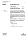
3.1 WHAT IS
TANKMASTER?
What is TankMaster? . . . . . . . . . . . . . . . . . . . . . . . . page 3-1
TankMaster Software Package . . . . . . . . . . . . . . . . page 3-2
Installing the TankMaster Software . . . . . . . . . . . . . page 3-4
Installing a Tank Level Gauging System . . . . . . . . page 3-6
Illegal characters . . . . . . . . . . . . . . . . . . . . . . . . . . . page 3-6
TankMaster is a software package designed by Emerson Process
Management/Rosemount Tank Gauging for inventory management as well
as configuration of level gauging equipment. The TankMaster program
package provides you with powerful and easy-to-use tools for installation and
configuration of Rosemount’s tank gauging system. Devices such as field
communication units, Tank Hubs, and radar level gauges can easily be
installed.
The operator’s interface provides inventory and custody transfer functions
and gives you a clear overview of installed devices and tanks. For each tank
you can easily see the associated transmitters and data acquisition units.
TankMaster is designed to be used in the Microsoft® Windows XP or Vista
environment providing easy access to measurement data from your Local
Area Network.
The TankMaster system allows you to use various protocols such as the
TRL2 Modbus and Enraf GPU. Interfaces such as RS232, and RS485 can be
used for communication with field devices. TankMaster clients and servers
can be integrated in Local Area Networks (LAN) for maximum availability. You
can easily change protocol, device, and tank configuration at any time.
Measured data is presented in real-time and you can customize the view of
tank data to suit your needs.
Key Features
www.rosemount-tg.com
•
Monitoring of measured data.
•
Clear overview of installed tanks and devices.
•
Simple installation by using “wizards”.
•
Open connectivity.
•
Object-oriented user friendly Graphical User Interface.
System Configuration Manual
300510EN, Rev AA
December 2010
Rosemount Raptor
3.2 TANKMASTER
SOFTWARE
PACKAGE
Rosemount TankMaster includes several software modules:
•
WinOpi
•
WinSetup
•
Tank Server
•
Master Protocol Servers
•
Slave Protocol Server
•
Batch Server
•
Administrator
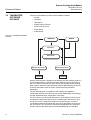
Figure 3-1. TankMaster software
modules
WINSETUP
WINOPI
Tank Server
Batch Server
Master Protocol Server
COM1/USB
Slave Protocol Server
COM2/USB
WinOpi is the operator´s interface to the Rosemount Tank Gauging system. It
communicates with the Tank Server and the different protocol servers to let
the user monitor measured tank data. WinOpi also provides alarm handling,
batch reports, automatic report handling, historical data sampling as well as
inventory calculations such as volume, observed density and other
parameters.
The WinSetup program is a graphical user interface for installation,
configuration and service of devices such as the 5900S Radar Level Gauge
and the 2240S Multi-input Temperature Transmitter.
The Tank Server communicates with devices via the Master protocol server
and handles configuration data for all the installed tanks and devices. Tank
and device names, configuration data such as antenna type, number of
connected temperature elements and many other parameters are stored by
the Tank Server. The Tank Server collects measured data from connected
devices and provides these data to the WinOpi/WinSetup user interface.
3-2
Section 3. Using TankMaster
System Configuration Manual
300510EN, Rev AA
December 2010
Rosemount Raptor
The Master Protocol Server transfers configuration data and measured data
between the Tank Server and connected devices in a Rosemount Tank
Gauging system. The Master Protocol Server is able to communicate with
various types of field devices such as radar level gauges, field communication
units, temperature transmitters, and pressure sensors to collect measured
data such as level, temperature, and pressure.
The Slave Protocol Server is used to connect the TankMaster system to a
host computer (DCS system). The Slave Protocol Server exchanges tank
data between the Tank Server and the host computer.
The Batch Server provides functions for starting, monitoring and closing batch
transfers betweeen tanks. It also generates various reports during and after a
batch transfer.
The Administrator program allows you to start and stop TankMaster, and to
specify which TankMaster software modules that will start automatically when
the PC starts up. It also includes a backup and restore function, and functions
for handling redundant Tank Servers and Batch Servers.
OPC Server with Browser
TankMaster uses OPC Data Access 2.0 (OLE for Process Control), an open
industry standard, which eliminates the need for costly customized software
integration. With the OPC server and the browser it is easy to import all
custody transfer and inventory data to other OPC clients such as different
DCS:s, PLC:s, Scada systems, or Microsoft Office programs. This way,
operators and plant management are better armed to make timely decisions
as they work with distributed inventory and tank gauging data. (Website OPC
Foundation: www.opcfoundation.org).
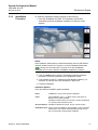
Customized views
In TankMaster you can change general and specific tank view and setup
windows. There are a number of options to design TankMaster as you like;
you can either modify the existing windows or design completely new ones.
For example you can have a photo of the plant giving a quick realistic view
and just by clicking a specific tank you will get corresponding tank data.
Section 3. Using TankMaster
3-3
System Configuration Manual
300510EN, Rev AA
December 2010
Rosemount Raptor
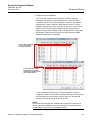
3.3 INSTALLING THE TANKMASTER SOFTWARE
3.3.1
System
Requirements
The following system specification is recommended to run TankMaster
version 5.B0 or higher(1):
General
Product
Operating system
Rosemount TankMaster; WinOpi, Winsetup, WinView
English version of:
• Windows XP Professional Edition. Service pack SP2 or SP3
• Windows 2003 Server with service pack 2 (SP2)
• Windows Vista with service pack 1(SP1)
TankMaster PC
Hardware
Processor
• Windows XP: 2 GHz Intel Pentium double processor
• Windows Vista / Windows 2003 Server: 2.5 GHz Intel Pentium
double processor
Internal Memory (RAM)
• Windows XP: 2 GB (1 GB for clients)
• Windows Vista / Windows 2003 Server: 3 GB
Recommended brand
Hard Disk
Serial Port
Monitor
Graphics card
Hardware key
IBM or DELL PC (Windows XP or Windows Vista approved).
40 GB (TankMaster + SQL Server 2005 Express needs
approximately 600 MB).
RS232, or USB if a FBM2180 fieldbus modem is used
A 22 inch or larger monitor is recommended.
1152*864, 65536 colors (16 bit).
One key connected to a USB port for each PC with a TankMaster
server.
In custody transfer systems a hardware key connected to a
parallel port is also required.
NOTE
A hardware key is not required to run WinSetUp.
3.3.2
Installed
Software
Modules
The following software program modules are installed:
(1)
3-4
•
TankMaster WinSetup program
•
TankMaster WinOpi program
•
Tank Server
•
Modbus Master Protocol server
•
Various Master Protocol servers
•
Various Slave Protocol servers
•
Batch server
For previous TankMaster versions other system requirements apply. Please contact Emerson Process Management/Rosemount Tank Gauging for more information.
Section 3. Using TankMaster
System Configuration Manual
300510EN, Rev AA
December 2010
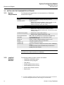
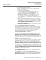
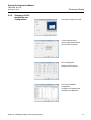
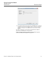
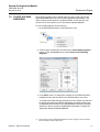
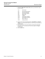
3.3.3
Installation
Procedure
Rosemount Raptor
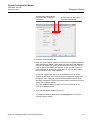
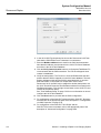
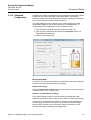
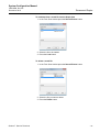
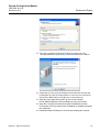
To install the TankMaster software package do the following:
1. Insert the TankMaster CD-ROM. The installation wizard starts
automatically and the TankMaster installation CD start-up screen
appears:
NOTE!
If the installation wizard does not start automatically when the CD-ROM is
inserted, double-click the file Tmcd.exe or click the Windows Start button
, choose Run and select the Tmcd.exe file on the TankMaster
installation CD in order to start the TankMaster installation procedure.
2. Click the Install button to start the TankMaster software installation
procedure. Follow the instructions in the installation wizard.
3. If not available on the PC, install the Acrobat Reader software if you
would like to read the online documentation in pdf format.
4. Finish the installation.
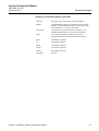
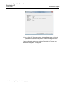
Installation Options
There are different installation options available:
Demo
TankMaster in demo mode with demo database.
Client
Client installation only, i.e. no Batch Server, Tank Server or
Master Protocol will be installed.
Suitable for network clients connected to a common Tank Server
or in systems with redundant servers.
Server and Client Suitable for standalone systems, and for network servers.
Redundant server Server and client installation with possibility to setup redundant
Tank Servers. Note that the redundant Batch Server function
has to be manually configured after installation.
Section 3. Using TankMaster
3-5
System Configuration Manual
300510EN, Rev AA
December 2010
Rosemount Raptor
3.4 INSTALLING A
TANK LEVEL
GAUGING SYSTEM
Setting up a Tank Level Gauging system comprises installation and
configuration of devices and tanks.
Tank installation
Tank installation includes specifying tank type, specifying transmitters to
associate with the tank, and to define which source signals to use as input for
various tank measurement variables.
Device installation
Device installation includes tasks such as configuration of field bus
communication, specifying tank height and other geometrical parameters,
configuration of device specific parameters for radar level gauges,
temperature and pressure transmitters.
Wizards
In order to facilitate the installation process, TankMaster WinSetup guides you
through the installation procedure by using so called “wizards”. WinSetup
automatically walks through a step-by-step procedure which lets you focus on
the important issues rather than trying to remember what to do next. The
Online Help provides information for each step in case you need further
assistance.
3.5 ILLEGAL
CHARACTERS
3-6
Naming objects in TankMaster using certain characters may cause
TankMaster to malfunction. The following characters should be avoided:
\
Reverse solidus
%
Percent sign
/
Solidus
<
Less-than sign
?
Question mark
>
Greater-than sign
*
Asterisk
{
Left curly bracket
[
Left square bracket
}
Right curly bracket
]
Right square bracket
'
Apostrophe
|
Vertical line
"
Quotation mark
Section 3. Using TankMaster
System Configuration Manual
300510EN, Rev AA
December 2010
Rosemount Raptor
Section 4
The WinSetup Main Window
4.1
4.2
4.3
4.4
4.5
Menus . . . . . . . . . . . . . . . . . . . . . . . . . . . . . . . . . . . . page 4-3
Toolbar . . . . . . . . . . . . . . . . . . . . . . . . . . . . . . . . . . . . page 4-4
Status bar . . . . . . . . . . . . . . . . . . . . . . . . . . . . . . . . . page 4-5
Workspace - Viewing Tanks and Devices . . . . . . . . page 4-6
User Management . . . . . . . . . . . . . . . . . . . . . . . . . . . page 4-9
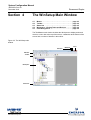
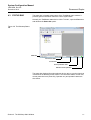
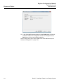
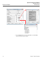
The TankMaster main window includes the Workspace to display tanks and
devices, a menu bar at the top of the screen, a status bar at the bottom of the
screen and a number of buttons in the toolbar.
Figure 4-2. The WinSetup main
window
Minimize
Menubar
Toolbar
Workspace
Status bar
www.rosemount-tg.com
Maximize
Close
System Configuration Manual
Rosemount Raptor
300510EN, Rev AA
December 2010
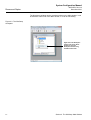
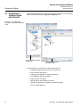
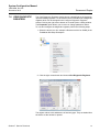
The Workspace window can be moved anywhere on the Main window. It can
be docked to either side of the Main window, or it can be left floating.
Figure 4-3. The WinSetup
workspace
Right click in the Workspace
window and choose Allow
Docking to place the
Workspace window along
the Main window side.
4-2
Section 4. The WinSetup Main Window
System Configuration Manual
300510EN, Rev AA
December 2010
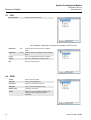
4.1 MENUS
Rosemount Raptor
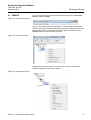
The menu bar at the top of the screen contains menus such as File, View,
Service, Tools, and Help.
Figure 4-4. The WinSetup menu
Service menu options are also available by clicking the right mouse button.
Different options are available depending on the type of object selected in the
Workspace window. For example, clicking the right mouse button on the
Devices folder will open the following menu:
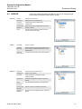
Figure 4-5. The Service menu
Clicking the right mouse button on a device icon brings up a menu with
different configuration and service options:
Figure 4-6. The WinSetup menu
Section 4. The WinSetup Main Window
4-3
System Configuration Manual
300510EN, Rev AA
December 2010
Rosemount Raptor
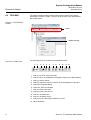
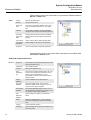
4.2 TOOLBAR
The toolbar provides buttons acting as shortcuts to certain menu options.
Normally the Toolbar is visible. To hide it, open the View menu and deselect
the Toolbar option:
Figure 4-7. The WinSetup
Toolbar
Toolbar
Hide/Show Toolbar
The following items are included in the standard toolbar:
Figure 4-8. Toolbar items
1
2
3
4
5
6
7
8
9
10
11
12
1. Lets you log off to View Only mode.
2. Lets you log on to TankMaster as Operator, Supervisor or Administrator.
3. Lets you rename a tank.
4. Lets you search for a tank or a device in the workspace tree structure.
5. Opens the Properties dialog.
6. Opens the Tank View window.
7. Lets you install a new tank.
8. Lets you install a new device.
9. Lets you uninstall a tank.
10. Lets you uninstall a device.
11. Lets you turn the Workspace window On or Off.
12. About WinSetup
4-4
Section 4. The WinSetup Main Window
System Configuration Manual
300510EN, Rev AA
December 2010
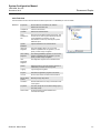
4.3 STATUS BAR
Rosemount Raptor
The status bar is located at the bottom of the TankMaster main window. It
provides general information about the current system state.
Normally, the TankMaster status bar is visible. To hide it, open the View menu
and deselect the Status bar option.
Figure 4-9. The Winsetup Status
bar
Status bar
Connection status
Current user
Current protection level
Indicator normal operation
The status bar displays information about a device, tank or any other item that
is selected in the WinSetup main window. The connection status, current user,
current protection level (View Only, Operator etc.) and operation status are
also shown.
Section 4. The WinSetup Main Window
4-5
System Configuration Manual
300510EN, Rev AA
December 2010
Rosemount Raptor
4.4 WORKSPACE VIEWING TANKS
AND DEVICES
The workspace displays an overview of all devices and tanks. You can switch
between two different views: Logical and Physical view.
Figure 4-10. The Winsetup
workspace Logical and Physical
views
Choose this tab to show the
Logical View.
Choose this tab to show
the Physical View.
In the workspace you can perform various tasks such as:
4-6
•
Install and configure tanks, devices, and protocols
•
Remove tanks and devices
•
Change the configuration of tanks and devices
•
View database and input registers
•
Setup the tank view layout
•
Specify tags for tank and device names
•
Upload new application software to a radar tank gauge
•
View communication log
Section 4. The WinSetup Main Window
System Configuration Manual
300510EN, Rev AA
December 2010
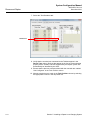
4.4.1
Workspace
Rosemount Raptor
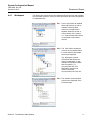
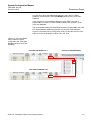
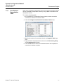
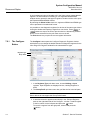
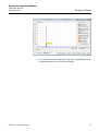
The Workspace window shows the installed tanks and devices and available
communication protocols. It also provides information about the configuration
of installed devices.
Ex.1 In the Logical View all installed
tanks and devices, as well as
available communication
protocols, are organized in
separate folders to provide a
clear overview of the system.
A “+”-sign indicates that a device
is connected to associated
devices.
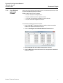
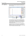
Ex.2 The Tanks folder contains an
overview of the installed tanks.
For each tank the associated
devices are displayed.
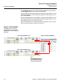
The Workspace provides
information that reflects the
system configuration. In this
example the symbols indicate
that level gauge LT-1
communicates with This
Workstation via tank hub
HUB-101 and field
communication unit FCU-201.
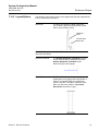
Ex.3 The available communication
protocols are displayed in the
Protocols folder.
Section 4. The WinSetup Main Window
4-7
System Configuration Manual
300510EN, Rev AA
December 2010
Rosemount Raptor
4.4.2
Icons
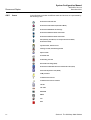
In the Workspace window the different tanks and devices are represented by
the following icons:
Rosemount 2410 Tank Hub
Rosemount 2410 Tank Hub (Simulation Mode)
Rosemount 5900S Radar Level Gauge
Rosemount 5400 Series Radar Transmitter
Rosemount 5300 Series Radar Transmitter
ATD (Auxiliary Tank Device; for example Rosemount 2240S,
Rosemount 3051S)
Cylindrical tank, HTG fixed roof
Floating roof tank, HTG floating blanket
Spherical tank
Horizontal tank
HTG floating roof tank
Rex Radar Tank Gauge (RTG)
Rosemount 2160/2165/2175 Field Communication Unit (FCU)
Slave Data Acquisition Unit (SDAU)
COM port status
Communication Protocol
Communication Protocol Channel
TRL PU
IOT 51XX
MCG32XX
MDPII
CIU
DS4
4-8
Section 4. The WinSetup Main Window
System Configuration Manual
300510EN, Rev AA
December 2010
4.5 USER
MANAGEMENT
Rosemount Raptor
TankMaster provides several protection levels allowing you to prevent
unauthorized changes. These protection levels are categorized as User
Access Levels and User Sub Access Levels.
The User Access Levels are Chief Administrator, Administrator, Supervisor,
Operator, and View Only. Each user access level has five User Sub Access
Levels providing a total of 25 unique access levels.
In order to change tank and device configuration, install new tanks and
devices, calibrate a level gauge, change holding register values etc. you have
to be logged on to the appropriate TankMaster user access level. See “To Set
Required Access Levels” on page 4-13 for more information.
You can be logged on in Chief Administrator, Administrator, Supervisor,
Operator, or View Only mode. The default usernames and passwords for the
User Access Levels are:
Table 4-1. Usernames and
passwords for different user
access levels
User Access Level
Username
Password
View Only
Default username: view
Default password: view
Operator
Default username: operator
Default password: oper
Supervisor
Default username: supervisor
Default password: super
Administrator
Default username: administrator
Default password: admin
ChiefAdministrator
Default username: chiefadmin
Default password: chief
Section 4. The WinSetup Main Window
4-9
System Configuration Manual
300510EN, Rev AA
December 2010
Rosemount Raptor
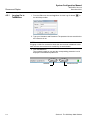
4.5.1
Logging On to
TankMaster
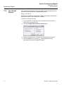
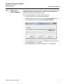
1. From the File menu choose Log On or click the Log On button
the WinSetup toolbar.
in
2. Type your Username and Password. The password is case sensitive but
the username is not.
NOTE!
If logging on fails five consecutive times the user account is disabled. In this
case the user account has to be enabled by an administrator.
3. Click the OK button.
The currently logged on user and the corresponding protection level is
displayed in the WinSetup status bar.
Username
4-10
User Access Level
Section 4. The WinSetup Main Window
System Configuration Manual
300510EN, Rev AA
December 2010
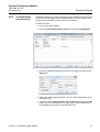
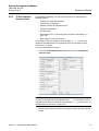
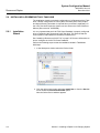
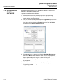
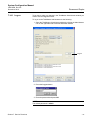
4.5.2
To Administrate
User Accounts
Rosemount Raptor
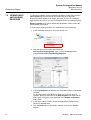
TankMaster allows you to setup a number of users at different levels and sub
levels. You must be logged on as an Administrator in order to add new user
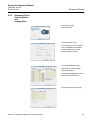
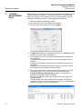
accounts or to change the existing user account settings.
To add a new user:
1. Log on as an Administrator.
2. From the Tools>Administrative Tools menu choose User Manager.
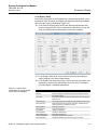
3. In the User Manager window select a cell in an empty row and click the
New button.
4. Type a user name and a password. If you like, enter a description in the
Description field.
5. Choose the desired User Access Level and Sub Level and click the OK
button. See “User Management” on page 4-9 for further information on
the available User Access Levels and Sub Levels.
Section 4. The WinSetup Main Window
4-11
System Configuration Manual
300510EN, Rev AA
December 2010
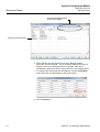
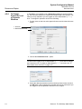
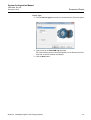
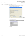
Rosemount Raptor
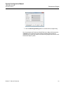
Use first account with required
access level as default
A new user account is added
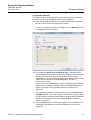
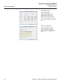
6. Check that the new user appears in the User Manager window.
Select the “Use first account...” box if you want a default user name to
appear in the Log On dialog whenever it is opened. If this box is
unmarked the User Name field is empty when the Log On dialog opens.
7. To configure the access sub level descriptions, click the Config Desc
button and enter new descriptions in the various fields.
8. Click the OK button.
4-12
Section 4. The WinSetup Main Window
System Configuration Manual
300510EN, Rev AA
December 2010
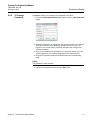
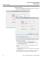
4.5.3
To Set Required
Access Levels
Rosemount Raptor
In TankMaster WinSetup, you can set the access level required for the
following actions:
•
Tank/Device Install and Uninstall
•
Tank/Device Configuration
•
Replace, Restore and Restart Device
•
Protocol Configuration
•
Exit WinSetup
•
Add Program (see “Customizing the Tools Menu in WinSetup” on
page 7-2)
•
Start Program (in the Tools menu)
For example, if you are logged on as an Operator (* * * * *), you are not
allowed to exit WinSetup if the required exit level for this action is set to
Supervisor (*) or higher.
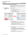
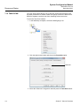
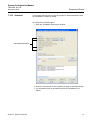
To set the required access levels:
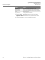
1. From the Tools/Administrative Tools menu choose Set Required
Access Levels.
NOTE!
You have to be logged on as an Administrator (* * * * *) to be able to set the
required access levels. To create an Administrator (* * * * *) account, see “To
Administrate User Accounts” on page 4-11.
2. Set the required access levels for each type of action and click the OK
button.
Section 4. The WinSetup Main Window
4-13
System Configuration Manual
300510EN, Rev AA
December 2010
Rosemount Raptor
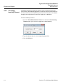
4.5.4
To Change
Protection Level
of Separate
Windows
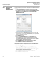
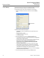
In TankMaster it is possible to set a Protection Level for a specific window,
e.g. the Properties window for a Rosemount 5900S Radar Level Gauge. This
function is only available if you are logged on at the Administrator (* * * * *)
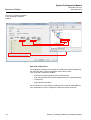
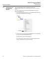
level. To change the protection level do the following:
1. Put the cursor on the icon at the upper left corner and click the left mouse
button.
1. Click icon.
2. Select Protection Level.
2. Choose the Protection Level... option.
NOTE!
You have to be logged on as an Administrator (* * * * *) to be able to change
the Protection Level. To create an Administrator (* * * * *) account, see “To
Administrate User Accounts” on page 4-11.
3. Select the desired protection level from the drop down menus and click
the OK button. Now changes in this window can only be performed if you
are logged on at the specified Protection Level or higher.
4-14
Section 4. The WinSetup Main Window
System Configuration Manual
300510EN, Rev AA
December 2010
4.5.5
To Change
Password
Rosemount Raptor
TankMaster allows you to change your password at any time:
1. From the Tools/Administrative Tools menu choose the Set Password
option.
2. Select the TankServer on which your user account is valid. You can see
the different servers in the WinSetup workspace window. (If you are
logged on, the current server is already selected in the Change User
Password window).
3. Enter your username if the workspace is in View Only mode. If you are
already logged on, your username appears in the Username field.
4. Enter the old password and the new password in the corresponding
fields.
NOTE!
The password is case sensitive.
5. Confirm the new password and click the OK button.
Section 4. The WinSetup Main Window
4-15
System Configuration Manual
300510EN, Rev AA
December 2010
Rosemount Raptor
4.5.6
To Change
Inactivity Timeout
TankMaster WinSetup includes the option to set a timeout after which the
current user is automatically logged off. The timeout period is reset each time
the user performs an activity that requires an access level check, for example
changing the configuration of a device or logging on to WinSetup.
To set the Inactivity Timeout:
1. From the Tools/Administrative Tools menu choose the Set Inactivity
Timeout option (you have to be logged on as Administrator).
2. Type the desired value in the corresponding input field.
3. Click the OK button.
4-16
Section 4. The WinSetup Main Window
System Configuration Manual
300510EN, Rev AA
December 2010
Section 5
Rosemount Raptor
Installing a Raptor Level
Gauging System
5.1
5.2
5.3
5.4
5.5
5.6
5.7
5.8
5.9
5.10
5.11
5.12
5.13
5.14
5.15
5.16
www.rosemount-tg.com
System Configuration Overview . . . . . . . . . . . . . . . page 5-2
Communication Protocol Setup . . . . . . . . . . . . . . . page 5-6
Preferences . . . . . . . . . . . . . . . . . . . . . . . . . . . . . . . . page 5-16
Field Device Installation - Overview . . . . . . . . . . . . page 5-24
Installing a Rosemount 2160 FCU . . . . . . . . . . . . . . page 5-25
Installing a Rosemount 2410 Tank Hub . . . . . . . . . page 5-38
Installing a Rosemount 5900S Radar Level Gauge page 5-51
Installing Auxiliary Tank Devices . . . . . . . . . . . . . . page 5-65
Installing a Rosemount 5400 . . . . . . . . . . . . . . . . . . page 5-78
Installing a Rosemount 5300 . . . . . . . . . . . . . . . . . . page 5-90
Installing a Tank . . . . . . . . . . . . . . . . . . . . . . . . . . . . page 5-101
Adding a Tank to a Raptor System . . . . . . . . . . . . . page 5-114
Level Gauge Calibration . . . . . . . . . . . . . . . . . . . . . page 5-122
Tank Capacity . . . . . . . . . . . . . . . . . . . . . . . . . . . . . . page 5-124
Tank Entry . . . . . . . . . . . . . . . . . . . . . . . . . . . . . . . . . page 5-125
Setting up a Hybrid System . . . . . . . . . . . . . . . . . . . page 5-126
System Configuration Manual
300510EN, Rev AA
December 2010
Rosemount Raptor
5.1 SYSTEM CONFIGURATION OVERVIEW
5.1.1
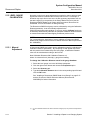
5.1.2
Preparations
Installation
Procedure
Before installing a Rosemount Tank Gauging system you should ensure that
the following information is available:
•
A plan of all field devices and tanks.
•
Unit IDs of each device (Unit ID is a unique identifier given to each
Raptor device at factory).
•
Modbus addresses of level devices and ATD devices. The Raptor
devices are shipped with default addresses which will be changed at
system configuration. The Modbus addresses are configured in the
Slave Database of the 2160 FCU and the Tank Database of the 2410
Tank Hub as described below.
•
Tank geometry parameters and reference distances such as tank
reference height (R) and distance between Zero level (datum plate)
and tank bottom.
•
Antenna types used for the various level gauges.
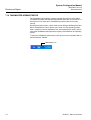
Installation and configuration of a Rosemount Raptor level gauging system
includes the following steps as briefly described below:
1 Communication Protocol Setup
Specify communication protocol parameters:
•
The Modbus Master Protocol handles communication between a
TankMaster work station and field devices such as the Rosemount
2160 Field Communication Unit and the Rosemount 2410 Tank Hub.
•
The Slave Protocol handles communication with a host computer.
•
Communication with TankMaster can be supervised by logging various
error types and function codes.
2 Preferences
Specify measurement units, tag prefixes for tank and device labels,
inventory parameters, and parameters to be displayed when viewing tank
data.
3 Installation and Configuration of 2160 Field Communication Unit
The Rosemount 2160 Field Communication Unit (FCU) has to be installed
and configured prior to installing other devices such as a Rosemount 2410
Tank Hub and a Rosemount 5900S Radar Level Gauge.
To install a Rosemount 2160 FCU:
5-2
•
Assign a Modbus communication address
•
For each communication port, configure protocol and appropriate
communication parameters
•
Configure the Slave Database with information about the devices
connected to the fieldbus
Section 5. Installing a Raptor Level Gauging System
System Configuration Manual
300510EN, Rev AA
December 2010
Rosemount Raptor
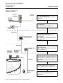
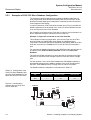
Figure 5-1. Raptor system
installation procedure
Plant Host
Computer
TankMaster
workstattion
1. Communication setup.
See “Communication Protocol Setup” on
page 5-6.
2. Preferences.
See “Preferences” on page 5-16.
Rosemount 2180
Field Bus Modem
GROUP BUS
Rosemount 2160 Field
Communication Unit
FIELD BUS
Rosemount
5900S Radar
Level Gauge
Rosemount 2240S
Multi-Input
Temperature
Transmitter
Rosemount 2410
Tank Hub
TANKBUS
3. Rosemount 2160 Field
Communication Unit installation and
configuration.
See “Installing a Rosemount 2160 FCU”
on page 5-25.
4. Rosemount 2410 Tank Hub installation
and configuration.
See “Installing a Rosemount 2410 Tank
Hub” on page 5-38.
5. Device installation and configuration.
See for example “Installing a Rosemount
5900S Radar Level Gauge” on page 5-51
and “Installing Auxiliary Tank Devices” on
page 5-65.
6. Tank installation and configuration.
See “Installing a Tank” on page 5-101.
Rosemount 2230
Graphical Field
Display
Section 5. Installing a Raptor Level Gauging System
7. Calibration.
See “Level Gauge Calibration” on
page 5-122.
5-3
System Configuration Manual
300510EN, Rev AA
December 2010
Rosemount Raptor
4 Installation and Configuration of Rosemount 2410 Tank Hub
The Rosemount 2410 should be installed after the Rosemount 2160 Field
Communication Unit. In case the Rosemount 2410 is connected directly to
a TankMaster work station without a 2160 FCU, the 2410 has to be
installed before the other field devices. To install a 2410 do the following:
•
Specify a device tag
•
Assign a Modbus communication address
•
Configure the 2410 Tank Database which maps devices to tanks
•
Configure the optional local display
5 Installation and Configuration of Field Devices
When setting up a Raptor level gauging system the field devices, such as
level gauges and temperature transmitters, are installed in TankMaster
Winsetup as part of the Rosemount 2410 installation procedure. The
devices are configured at a later stage by using the Properties window of
each device.
Installation and configuration of devices include the following steps:
Communication
Specify protocol and address.
Configuration
Specify tank geometry parameters, device specific
parameters, temperature element positions, and
other parameters depending on the device type.
6 Installation and Configuration of Tanks
Installing a tank includes the following steps:
Choose tank type
Select one of the available options such as Fixed
Roof, Floating Roof, Sphere LPG, Horizontal LPG,
or other suitable tank type.
Specify a tank tag
Specify a name to be used as an identifier in the
Workspace window and other TankMaster
windows.
Select devices
Associate devices to the tank.
Configuration
Specify the available source signals for parameters
such as Free Water Level, Vapor Pressure and
Liquid Pressure.
Value Entry
Specify an approved value range for each
measurement variable. In case there is no source
instrument available for a certain parameter, you
can specify manual values to be used instead.
7 Calibration
When a Rosemount 5900S Radar Level Gauge is installed and configured
the Calibration Distance may have to be adjusted in order to match
measured level and actual product level. The adjustment should be
performed once at the final commissioning.
5-4
Section 5. Installing a Raptor Level Gauging System
System Configuration Manual
300510EN, Rev AA
December 2010
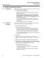
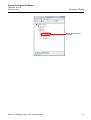
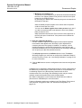
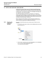
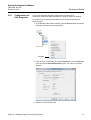
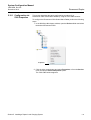
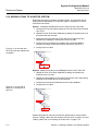
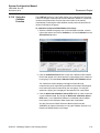
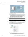
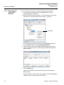
5.1.3
Using the Device
Installation
Wizard
Rosemount Raptor
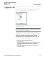
The device installation wizard guides you step-by-step through the installation
procedure. The wizard can be started in different ways:
1. Select the Devices folder.
2. Click the right mouse
button and choose Install
New from the popup
menu, or from the
Service>Devices menu
choose Install New.
As an alternative you can
use the following method:
1. Select the server where
your system is installed.
2. From the File>Install
New menu choose
Device.
See chapter 5.6 to 5.10 for detailed information on how to install different
devices.
Section 5. Installing a Raptor Level Gauging System
5-5
System Configuration Manual
300510EN, Rev AA
December 2010
Rosemount Raptor
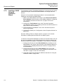
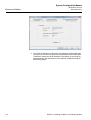
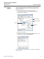
5.2 COMMUNICATION
PROTOCOL SETUP
The TRL2 Modbus Master protocol is available as default protocol when
Rosemount TankMaster is installed on a TankMaster work station. Other
protocols, such as the Modbus Slave protocol for communication with host
systems, can be obtained as option. Contact Emerson Process Management /
Rosemount Tank Gauging for more information.
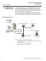
A protocol offers up to eight channels. For each channel you can specify
which PC communication port (USB/COM) to connect to, as well as standard
communication parameters such as Baud Rate and number of Stop Bits.
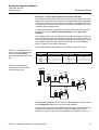
Figure 5-2. Communication with
various Raptor devices
SLAVE PROTOCOL
(PLC, SCADA, DCS)
To Host computer
2160 Field Communication Unit
2410 Tank Hub
RS485 or TRL2 Modbus
The TankMaster work station
can be connected to field
devices and host computers
by using Master and Slave
protocols
RS232 or RS485
Tankbus
5900S Radar
Level Gauge
MASTER PROTOCOL
TRL2 Modbus
2180 Field Bus Modem
For each protocol you can configure the following:
5-6
•
Communication parameters: COM Port, Baud rate, number of stop bits,
modem type, etc.
•
Log file: File name, file size, log schedule.
•
Tank mapping (for slave protocols only)
Section 5. Installing a Raptor Level Gauging System
System Configuration Manual
300510EN, Rev AA
December 2010
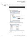
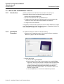
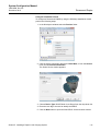
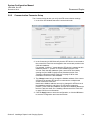
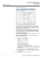
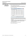
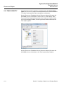
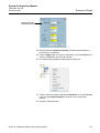
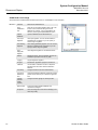
5.2.1
Master Protocol
Channel
Configuration
Rosemount Raptor
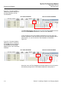
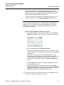
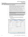
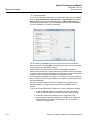
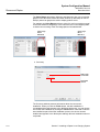
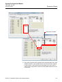
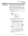
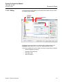
To configure a communication protocol do the following:
1. Open the Protocols folder in the Workspace window.
2. Select the icon that corresponds to the particular protocol to be
configured (this example will show the Modbus Master protocol).
1. Select the Modbus
Master protocol icon
2. Click the right mouse
button and select Properties
3. Click the right mouse button and select Properties, or choose
Protocols/Properties from the Service menu.
Properties
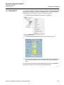
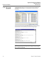
4. The Protocol Properties window lists an overview of protocol channels.
For each channel the corresponding icon indicates whether the channel
is enabled or disabled.
5. Select the desired channel.
6. Click the Properties button to configure the protocol channel.
Section 5. Installing a Raptor Level Gauging System
5-7
System Configuration Manual
300510EN, Rev AA
December 2010
Rosemount Raptor
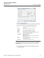
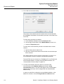
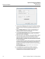
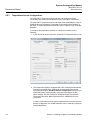
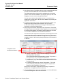
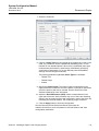
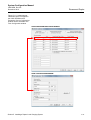
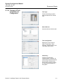
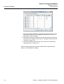
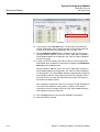
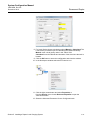
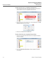
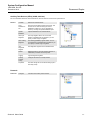
7. Select the Communication tab.
Parameters that control the communication between a TankMaster work
station and the field devices are configured in the Communication tab.
You can specify the type of information to be logged and saved to disk in
the File Log tab (see also “Log File Configuration” on page 5-14).
8. Set the communication parameters:
Port
The COM port that the Rosemount 2180 will be connected to
Baud rate
4800
Stop bits
1
Parity
None
Modem
Choose FBM for the Rosemount 2180 Field Bus Modem
Handshaking
FBM: RTS/CTS/DTR/DSR
RS485: RTS/CTS
RS232: None
Reply timeout
1000 ms
Retries
10
Description
Text describing the configured channel
NOTE!
If the communication is interrupted and handshaking includes DSR, no query
will be sent from the TankMaster Protocol Server. This may result in a Query
Timeout.
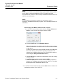
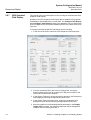
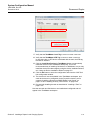
9. The Comm. disabled in backup mode check box can be used for
systems with redundant tank servers. If the check box is selected, the
ModbusMaster will not send any queries if the local tank server is in
backup mode.
10. Select the Enable Channel check box to activate the protocol channel.
11. Click the OK button to store the current configuration and close the
configuration window.
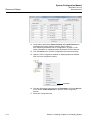
12. The Modbus Master Channel icon (channel no. 1 in this example)
appears in the WinSetup workspace:
5-8
Section 5. Installing a Raptor Level Gauging System
System Configuration Manual
300510EN, Rev AA
December 2010
Rosemount Raptor
Modbus Master channel 1
is enabled
Section 5. Installing a Raptor Level Gauging System
5-9
System Configuration Manual
300510EN, Rev AA
December 2010
Rosemount Raptor
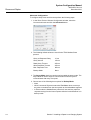
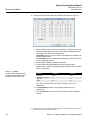
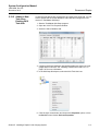
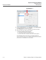
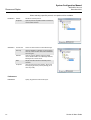
5.2.2
Slave Protocol
Channel
Configuration
A Slave protocol allows you to collect data from the TankMaster workstation to
a host computer.
NOTE!
A hardware key must be installed in order to run a slave protocol server.
TRL2 Modbus Communication Setup
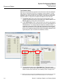
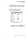
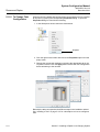
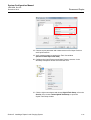
To configure the TRL2 Modbus Slave protocol channel do the following:
1. Open the Protocols folder in the Workspace window.
2. Select the ModbusSlave protocol icon.
1. Select the Modbus
Slave protocol
2. Click Properties
3. Click the right mouse button and select Properties, or choose
Protocols>Properties from the Service menu.
Properties
4. The Protocol Properties window lists enabled and disabled protocol
channels.
5. Select the desired channel.
6. Click the Properties button to configure the protocol channel.
5-10
Section 5. Installing a Raptor Level Gauging System
System Configuration Manual
300510EN, Rev AA
December 2010
Rosemount Raptor
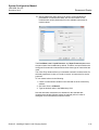
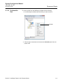
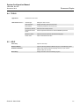
7. Select the Communication tab.
8. Select the Enable Channel check box to activate the protocol channel.
9. Ensure that the following communication parameters are set:
Port
Choose the COM port that the host computer will be
connected to.
Baud rate
Choose a setting that matches the host setting.
Stop bits
Choose a setting that matches the host setting.
Parity
Choose a setting that matches the host setting.
Modem
Choose the appropriate interface. Select FBM if you are using
a Rosemount 2180 Field Bus Modem.
Handshaking
FBM: RTS/CTS/DTR/DSR.
RS485: RTS/CTS.
RS232: See the specifications for the communication software
used on the host system.
Address
Set the address to be used by the host computer to identify
the TankMaster workstation.
Description
Text that describes the configured channel.
NOTE!
If handshaking includes DSR, no query will be sent from the TankMaster
Protocol Server if the communication is interrupted. This may result in a
Query Timeout.
10. Click the OK button to store the current configuration and close the
configuration window.
Section 5. Installing a Raptor Level Gauging System
5-11
System Configuration Manual
300510EN, Rev AA
December 2010
Rosemount Raptor
Advanced Configuration
To configure delay times and time-outs perform the following steps:
1. In the Slave Protocol Channel Configuration window, select the
Communication tab and click the Advanced button:
2. The following default values are used for the TRL2 Modbus Slave
protocol:
Query to Response Delay
10 ms
Query interval
100 ms
Read Query Timeout
400 ms
Write Response Timeout
400 ms
Max. Response Time
800 ms
Backup Mode
None
3. The Async Mode check box can be used to enable the async mode. The
Async Mode is used to improve communication when the system
communicates with many Com ports.
4. Choose one of the following three options for Backup Mode:
5-12
•
None
•
Write Commands Rejected means that TankMaster does not accept
any write commands from the host system to device database registers
•
In Silent mode the ModbusSlave protocol will not send any replies to
requests coming from the host computer while the local tankserver is in
backup mode
Section 5. Installing a Raptor Level Gauging System
System Configuration Manual
300510EN, Rev AA
December 2010
Rosemount Raptor
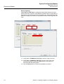
Tank mapping configuration
The slave protocol allows you to send data from a Rosemount Tank Gauging
system to a host computer. In the Tank Mapping window you can specify from
which tanks to collect data for the host system:
1. In the Slave Protocol Channel Configuration window, select the Tank
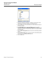
Mapping tab:
2. From the list of tanks that appear in the Available Tanks pane, select the
tanks that the host will connect to.
3. Click the
button to move the selected tanks to the list of Mapped
Tanks.
Ensure that the tanks appear in the order required by the host system.
When the host sends a query, TankMaster responds by sending tank
data in the order as the tanks are listed in the Mapped Tanks column.
You can easily change the position of mapped tanks by using the
and
buttons.
4. Click the OK button to save the current configuration and close the
window.
Section 5. Installing a Raptor Level Gauging System
5-13
System Configuration Manual
300510EN, Rev AA
December 2010
Rosemount Raptor
5.2.3
Log File
Configuration
See chapter “Saving the Communication Log to File” on page 7-39 for
information on how to store a communication log on disk.
5.2.4
Changing the
current Protocol
Channel
Configuration
The channel configuration can be changed at any time. Do the following:
1. In the WinSetup Workspace open the Protocols folder and the protocol
subfolder with the enabled channels.
Protocols
Protocol subfolder
2. Select the channel icon.
3. Click the right mouse button and choose Properties, or from the Service
menu choose Channels>Properties.
4. Choose the appropriate tab and change the protocol settings as
described in the previous sections.
5-14
Section 5. Installing a Raptor Level Gauging System
System Configuration Manual
300510EN, Rev AA
December 2010
5.2.5
Protocol Server
Configuration
Rosemount Raptor
You can specify which protocol servers that will be connected when starting
TankMaster WinSetup.
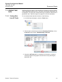
To change the current configuration do the following:
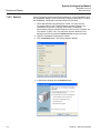
1. In the WinSetup workspace select the Protocols folder.
2. Click the right mouse button and choose Configure.
3. In the Connect column, select the check box of each protocol to be
automatically connected when WinSetup starts up.
You may disable a protocol server at any time by using the Disable command:
1. In the Winsetup workspace, open the Protocols folder.
2. Click the right mouse button on the protocol server icon and choose
Disable.
Section 5. Installing a Raptor Level Gauging System
5-15
System Configuration Manual
300510EN, Rev AA
December 2010
Rosemount Raptor
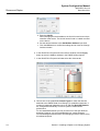
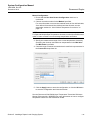
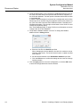
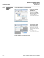
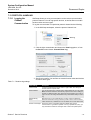
5.3 PREFERENCES
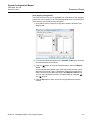
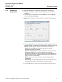
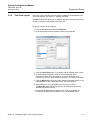
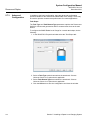
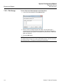
5.3.1
Measurement
Units
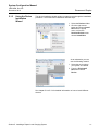
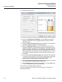
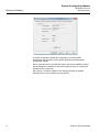
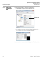
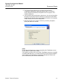
Specify units for inventory calculations and measured variables such as level
and temperature. To change measurement units do the following:
1. Select the desired server (e.g. “This Workstation”) in the WinSetup
workspace.
2. Click the right mouse button and choose Setup, or from the Service
menu choose Servers>Setup.
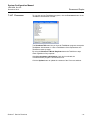
3. In the Server Preferences window select the Units tab.
4. Choose the desired measurement units for level/ullage, temperature,
pressure, volume, density, and weight.
5. Click the OK button to save the current setting and close the window.
NOTE!
Make sure that the desired measuring units are specified before installing new
tanks and devices.
Note that these settings only affect installation of new tanks. Tanks which are
already installed in the WinSetup Workspace will not be affected. In order to
change measurement units for an existing tank you have to do the following:
1. Uninstall the tank.
2. Change measurement units in the Server Preferences/Units window (or
in the TankMaster WinOpi program choose menu option Setup>System
and change units in the System Setup window).
3. Install the tank again.
5-16
Section 5. Installing a Raptor Level Gauging System
System Configuration Manual
300510EN, Rev AA
December 2010
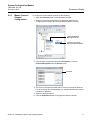
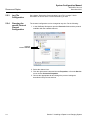
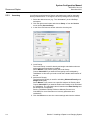
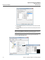
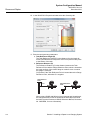
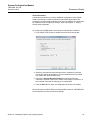
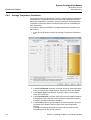
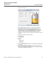
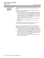
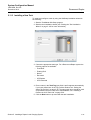
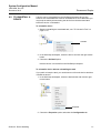
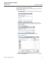
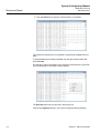
5.3.2
Ambient Air
Temperature
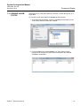
Rosemount Raptor
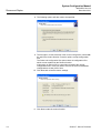
To change the Ambient Air Temperature preferences do the following:
1. Select the desired server (e.g. “This Workstation”) in the WinSetup
workspace.
2. Click the right mouse button and choose Setup, or from the Service
menu choose Servers>Setup.
3. In the Server Preferences window select the Ambient Air Temperature
tab:
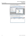
4. Choose Auto when there is a temperature sensor available that can be
used for Ambient Air Temperature measurements. Otherwise, select the
Manual option and type a value for the Ambient Air temperature.
•
Device. Click the
button and select the device to which a
temperature sensor is connected.
•
Ambient Air Temp Source. Select temperature source associated
with the selected device. In a Raptor system the associated
temperature transmitter has to be configured in the tank database of
the 2410 Tank Hub (see “Installing a Rosemount 2410 Tank Hub” on
page 5-38 for more information).
•
Sensor. Choose the specific sensor to be used for Ambient Air
Temperature.
•
Value Range. The Value Range defines the minimum and maximum
values when Ambient Air Temperature is manually entered.
5. Click the OK button to save the current setting and close the window.
Section 5. Installing a Raptor Level Gauging System
5-17
System Configuration Manual
Rosemount Raptor
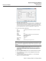
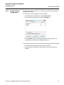
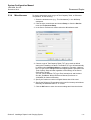
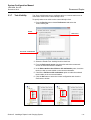
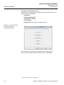
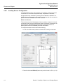
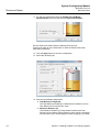
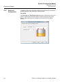
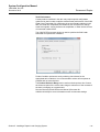
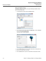
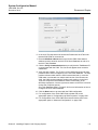
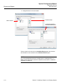
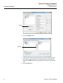
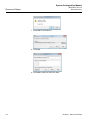
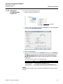
5.3.3
Inventory
300510EN, Rev AA
December 2010
Local Gravity and Ambient Air Density calculations are used for automatic
density measurements. To change the Inventory settings do the following:
1. Select the desired server (e.g. “This Workstation”) in the WinSetup
workspace.
2. Click the right mouse button and choose Setup, or from the Service
menu choose Servers>Setup.
3. In the Sever Preferences window select the Inventory tab:
4. Local Gravity.
The Local Gravity is used for density and weight calculations when an
optional pressure transmitter is installed.
Select Manual if you want to specify the Local Gravity.
Choose Calculated if you want the local gravity to be calculated by
TankMaster. In this case you need to enter the Latitude and Elevation of
the site.
5. Ambient Air Density.
The Ambient Air Density is used for calculating Observed Density and
Weight in Air (WIA).
Select Manual if you want to use a specific Ambient Air Density value.
Choose Calculated if you want the Ambient Air Density to be calculated
by TankMaster. The calculated value is based on the Base Density and
the Ambient Air Temperature.
See the TankMaster WinOpi Reference Manual (Document no.
303028EN) for more information on inventory parameters and
calculations.
6. Click the OK button to save the current settings and close the window.
5-18
Section 5. Installing a Raptor Level Gauging System
System Configuration Manual
300510EN, Rev AA
December 2010
5.3.4
Miscellaneous
Rosemount Raptor
To change parameters such as type of Tank Capacity Table, or Reference
Temperature, do the following:
1. Select the desired server (e.g. “This Workstation”) in the WinSetup
workspace.
2. Click the right mouse button and choose Setup, or from the Service
menu choose Servers>Setup.
3. In the Server Preferences window select the Miscellaneous tab.
4. Choose a type of Tank Capacity Table (TCT) to be used as default
setting when installing new tanks. The default TCT type will automatically
be chosen when strapping tables are created for new tanks. However,
the TCT type can be changed when the strapping table is specified in the
Tank Capacity Setup window regardless of the settings in the Server
Preferences window.
You can choose between TCT type Raw, International, and Northern.
See the TankMaster WinOpi Reference Manual (Document no.
303028EN) for further information.
5. Specify the maximum number of Digital Alarms that will be used.
6. Specify the Reference Temperature to be used for inventory calculations.
Normally, the standard value 15 °C is used.
7. Click the OK button to save the current settings and close the window.
Section 5. Installing a Raptor Level Gauging System
5-19
System Configuration Manual
300510EN, Rev AA
December 2010
Rosemount Raptor
5.3.5
Setting the Name
Tag Prefixes
TankMaster WinSetup allows you to specify default name tag prefixes that will
appear automatically when installing new tanks and devices. These prefixes
can be ignored if you want to use other prefixes instead.
To specify name tag prefixes do the following:
1. From the Service menu choose Preferences.
2. In the Preferences window select the Tag Prefixes tab.
3. Type the prefixes to be used for tank names and device names and click
the OK button.
You can change the prefixes later at any time. Note that this will not
affect names of existing tanks and devices.
5-20
Section 5. Installing a Raptor Level Gauging System
System Configuration Manual
300510EN, Rev AA
December 2010
5.3.6
Tank View Layout
Rosemount Raptor
The Setup Tank View tab is used to specify variables to be presented in the
Tank View window, see Section 7: Viewing Tank Data.
TankMaster WinSetup allows you to create a new tank view layout and store it
on disk, or load an existing table layout from disk.
To specify a layout do the following:
1. From the Service menu choose Preferences.
2. In the Preferences window select the Setup Tank View tab.
3. Click the Load Table button if you wish to edit an existing Table Layout.
4. In the Available Parameters pane on the left-hand side of the
Preferences/Setup Tank View window, select the parameter to be
presented in the Tank View window (see Section 7: Viewing Tank Data).
5. Click the Move button to move it to the Selected Parameters pane on the
right-hand side of the Preferences/Setup Tank View window.
6. Repeat steps 4 to 5 for each parameter you wish to include.
The Move All button allows you to move all variables at once to the
Selected Parameters list box.
7. Ensure that all parameters to appear in the Tank View window are
included in the Selected Parameters list box as illustrated below:
Section 5. Installing a Raptor Level Gauging System
5-21
System Configuration Manual
Rosemount Raptor
300510EN, Rev AA
December 2010
8. Click the Save As button if you wish to store the current tank view table
for future use.
9. Click the OK button to save the current Tank View settings and close the
window.
NOTE!
When clicking the Apply or the OK button, the parameter setup is stored in
the table layout that is currently used by the Tank View window.
To view the specified tank parameters click the right mouse button and
choose the Open Tank View option:
5-22
Section 5. Installing a Raptor Level Gauging System
System Configuration Manual
300510EN, Rev AA
December 2010
5.3.7
Rosemount Raptor
Tank Visibility
The Tanks Visibility tab lets you configure tanks on a remote tank server to
make them visible on the current WinOpi client.
To specify tanks to be visible on the current WinOpi client:
1. From the Service menu choose Preferences and select the
Tanks Visibility tab:
Enable
Tank Server
New tanks: visible/hidden
2. Select the Enable Tank Visibility function check box.
3. From the Select tank server drop-down list select the remote tank
server on which the tanks are installed.
4. In the Select tanks to be visible on this workstation pane, check the
tanks you wish to make visible on the current workstation.
5. Choose the Visible on this workstation option to make the selected
tanks visible on the current workstation.
6. Click the OK button to store the current configuration and close the
Preferences window.
Visible
Section 5. Installing a Raptor Level Gauging System
Hidden
5-23
System Configuration Manual
300510EN, Rev AA
December 2010
Rosemount Raptor
5.4 FIELD DEVICE
INSTALLATION OVERVIEW
The Rosemount TankMaster configuration software supports configuration of
all devices supported by the Raptor system:
•
Rosemount 5900S Radar Level Gauge
•
Rosemount 5400 Radar Level Transmitter
•
Rosemount 5300 Guided Wave Radar
•
Rosemount 2160 Field Communication Unit
•
Rosemount 2165/75 Field Communication Unit
•
Rosemount 2230 Graphical Field Display
•
Rosemount 2240S Multi-input Temperature Transmitter
•
Rosemount 2410 Tank Hub
•
Rosemount 3051/3051S Pressure Transmitter
•
Rosemount 644 Temperature Transmitter
Configuration
A TankMaster installation includes configuration of the Raptor system for
communication with the TankMaster work station, and configuration of device
specific parameters.
Configuration of a radar level gauge includes:
•
mapping to a specific tank in the tank database of the 2410 Tank Hub
•
setting up the communication parameters
•
selecting the antenna type
•
setting up the tank geometry
•
configuration of tank environment parameters
Configuration of a Auxiliary Tank Devices (ATDs) includes:
5-24
•
specifying communication address
•
mapping of measurement variables to source device
•
configuration of the 2240S Multi-input Temperature Transmitter
•
configuration of temperature elements
•
configuration of water level sensor
•
configuration of the 2230 Graphical Field Display
Section 5. Installing a Raptor Level Gauging System
System Configuration Manual
300510EN, Rev AA
December 2010
Rosemount Raptor
5.5 INSTALLING A ROSEMOUNT 2160 FCU
5.5.1
Introduction
Installing a Rosemount 2160 Field Communication Unit (FCU) in a
Rosemount Raptor system includes the following basic steps:
1. Specify device type and name tag.
2. Enable communication with the TankMaster PC.
3. Configure the Group bus and Field bus ports for communication with
Rosemount 2410 Tank Hubs and TankMaster work stations.
4. Configure the Slave Database.
Configuration examples that illustrate how the 2160 Slave Database is related
to the Tank Database of a 2410 Tank Hub is shown in “Examples of 2160 FCU
Slave Database Configuration” on page 5-32.
5.5.2
Installation
Procedure
To install and configure a 2160 FCU do the following:
1. Start the device installation wizard. See “Using the Device Installation
Wizard” on page 5-5 for more information.
2. Select device type:
a. Choose device type FCU 2160.
b. Specify a name of the Field Communication Unit in the FCU Tag
input field. This tag will be used as an identifier when the Rosemount
2160 is shown in various windows and dialogs. The TankMaster
program automatically suggests the first part of the name as
specified in the Tag Prefixes window, see “Setting the Name Tag
Prefixes” on page 5-20.
c. Click the Next button to continue the installation procedure.
Section 5. Installing a Raptor Level Gauging System
5-25
System Configuration Manual
300510EN, Rev AA
December 2010
Rosemount Raptor
3. FCU 2160 communication setup.
Choose the communication protocol channel which is associated with
the TankMaster workstation communication port that is connected to the
2160 FCU.
To check which channels are enabled:
a. in the WinSetup workspace open the Protocols folder
b. click the right mouse button on the ModbusMaster protocol icon
c. choose the Properties option
To check which communication port that is associated with a certain
channel:
a. right-click the protocol channel icon
b. open the Communication tab and check which communication port
that is selected
See chapter “Master Protocol Channel Configuration” on page 5-7 for
more information on how to configure communication protocols.
The 2160 FCU can be connected to a TankMaster PC via a Rosemount
2180 Field Bus Modem, or directly using the RS232 interface, see
“Communication Protocol Setup” on page 5-6.
4. To verify communication with the 2160 FCU, enter the Field
Communication Unit’s Modbus Address and click the Verify
Communication button. The Unit Id will appear if the correct Modbus
Address was entered (the 2160 is shipped with the default Modbus
address=245).
In case you would like to change the current Modbus address, or the
address is unknown, click the Change Address on Device button.
5-26
Section 5. Installing a Raptor Level Gauging System
System Configuration Manual
300510EN, Rev AA
December 2010
Rosemount Raptor
NOTE!
In case several FCUs are connected using the same default address (245),
you will have to change the addresses of the FCUs before the Verify
command can be used. See ”How to change the Modbus address of the FCU
2160” for more information.
NOTE!
For information on Field Communication Unit redundancy, see the
Rosemount TankMaster Redundancy System - User´s Guide (Document No.
303032EN).
How to change the Modbus address of the FCU 2160
a. In the FCU Communication window click the Change Address on
Device... button to open the Change Address window:
b. Enter the Unit ID and the new Modbus address.
When changing the device address, the Unit Id is used as a unique
identifier of the device. The Unit Id can be found on a label mounted
on the device.
(If there is no other device connected that uses the same address as
the current device, you can find the Unit Id by typing the current
address into the Address field in the FCU Communication window
and clicking the Verify Communication button).
c. Click the OK button to confirm the settings and to close the Change
Address window.
d. In the FCU Communication window click the Verify
Communication button to check if communication is established
between the TankMaster work station and the 2160 FCU. The Unit
ID will appear when TankMaster finds the 2160.
5. In the FCU Communication window click the Next button to continue the
installation procedure of the 2160 FCU.
Section 5. Installing a Raptor Level Gauging System
5-27
System Configuration Manual
300510EN, Rev AA
December 2010
Rosemount Raptor
6. Configure the Group Bus (GB) and Field Bus (FB) ports on the FCU.
a. Check that the correct port type is selected(1). The Rosemount 2160
has six communication ports. They are normally configured as two
Group Bus ports and four Field Bus ports.
Group Bus ports can be connected to TankMaster work stations as
well as to other hosts.
The Field Bus ports are connected to Rosemount 2410 Tank Hubs
and level gauging devices.
b. Ensure that the Modbus protocol is selected.
c. Ensure that the following Modbus protocol communication
parameters are used for the fieldbus that the Rosemount 2410 Tank
Hub is connected to:
Table 5-1. Modbus
communication parameters for
fieldbus communication with a
Rosemount 2410 Tank Hub
Parameter
RS485 bus
Baud rate
Databits per character
Stop bits
Parity
9600
8
1
No
TRL2 bus
4800
8
1
No
See “Communication Protocol Setup” on page 5-6 for more
information.
d. The Redundancy button is not used for stand-alone FCU
installations.
e. Click the Next button to open the FCU Properties/Slave Database
window.
(1)
5-28
As standard the 2160 FCU is equipped with FCM communication boards for the TRL2 bus.
RS-485 communication requires a FCI board.
Section 5. Installing a Raptor Level Gauging System
System Configuration Manual
300510EN, Rev AA
December 2010
Rosemount Raptor
7. Configure the Slave Database.
The FCU Slave Database ensures that the 2160 FCU requests
information from all the connected field devices. The 2160 FCU is
compatible with the TRL2 and Rex systems. Therefore, two Modbus
addresses are used for each tank. Each position in the FCU Slave
Database represents one tank. Positions 1A to 32A are used for level
gauges such as the Rosemount 5900S and other supported level
gauges. Positions 1B to 32B are used for Rosemount 2410 Tank Hubs
and Auxiliary Tank Devices (ATDs) such as the Rosemount 2240S
Multi-input Temperature Transmitter.
1. Select Slave Type=2410
Level for level gauges
connected to the 2410
2. Slave Type=2410 Temp is
automatically assigned for
temperature transmitters and
other auxiliary devices
It is very important that the 2160 FCU Slave Database is properly
configured to allow communication between the Rosemount 2160 Field
Communication Unit, the Rosemount 2410 Tank Hub, and the field
devices such as level gauges and other devices.
NOTE!
Once all devices and tanks are installed and configured, the position of a
device in the Slave Database may not be changed, since this will result in
corrupt mapping of tank to Slave Database position.
Section 5. Installing a Raptor Level Gauging System
5-29
System Configuration Manual
300510EN, Rev AA
December 2010
Rosemount Raptor
To configure the FCU Slave Database:
a. Select a free database position (1A, 2A ...) for the level gauge
device to be configured.
b. Choose Slave type=2410 Level.
The corresponding Slave Database position (1B, 2B ...) for
temperature transmitters and other auxiliary tank devices is
automatically assigned to Slave Type=2410 Temp.
c. Enter Modbus addresses for level gauges and auxiliary tank
devices (ATD). Ensure that the same database positions, .i.e.
1A/1B, 2A/2B and so on, are used for level gauges and ATDs on the
same tank.
d. Select the communication fieldbus (FB1, FB2, FB3, FB4) that the
Rosemount 2410 is connected to. Normally there are four fieldbus
ports available on the 2160 Field Communication Unit. The RS485
bus is the standard fieldbus interface for a Rosemount 2410 Tank
Hub connected to a Rosemount 2160 FCU.
e. If temperature elements are installed in the tank, type the number of
elements in the Temp column.
The 2160 Slave Database and the 2410 Tank Database
In a typical Raptor system a Rosemount 2160 FCU collects measurement
data from a number of tanks via one or more Rosemount 2410 Tank Hubs.
The Modbus addresses of the field devices on the tank need to be stored in
the 2160 FCU slave database as well as in the Rosemount 2410 tank
database for proper communication with the control room PC.
Level Gauge Modbus Address - 2410 Level
The 2410 Level address field in the 2160 FCU slave database is used for
level gauges such as the Rosemont 5900S. This address also needs to be
stored in the 2410 tank database as the Level Modbus address. This is
normally done as part of the installation procedure of the Rosemount 2410 as
described in chapter “Installing a Rosemount 2410 Tank Hub” on page 5-38.
ATD Device Modbus Address - 2410 Temp
The 2410 Temp Modbus address in the 2160 FCU slave database is used for
all devices on a tank except level gauges. This address also needs to be
stored in the ATD Modbus address field of the 2410 tank database. This is
normally done as part of the installation procedure of the Rosemount 2410 as
described in chapter “Installing a Rosemount 2410 Tank Hub” on page 5-38.
The first tank in the 2410 tank database uses the Modbus address of the 2410
Tank Hub itself as the ATD Modbus address. Tank number two, three etc. use
separate ATD Modbus addresses. The 2410 Modbus address is automatically
set as the ATD Modbus address for tank position 1 in the 2410 Tank Database
as illustrated in Figure 5-5 on page 5-34.
It is recommended that address range 1 to 99 is used for level gauges and
101 to 199 for ATD devices.
See “Examples of 2160 FCU Slave Database Configuration” on
page 5-32 for further information on how to configure the Slave Database of
the 2160 Field Communication Unit (FCU) and the Tank Database of the
Rosemount 2410 Tank Hub.
5-30
Section 5. Installing a Raptor Level Gauging System
System Configuration Manual
300510EN, Rev AA
December 2010
Rosemount Raptor
Summary of FCU Slave Database entry fields
Slave type
2410 Level, (pos 1A-32A) or 2410 Temp, (pos 1B-32B)
Address
The Modbus address used for the connected devices. For level
gauges it is recommended that address 1 to 99 is used. For ATD
devices address 101 to 199 are recommended.
FCU field bus
The field bus that the selected device is connected to. In the
standard configuration there are four field buses available.
Temps
The number of temperature elements connected to the
temperature transmitter (for example a Rosemount 2240S).
Ain/Cin
Automatically configured
Hin
Automatically configured
Relays
Automatically configured
Interval 1
Automatically configured
Interval 2
Automatically configured
Level Offset
Not used
Section 5. Installing a Raptor Level Gauging System
5-31
System Configuration Manual
300510EN, Rev AA
December 2010
Rosemount Raptor
5.5.3
Examples of 2160 FCU Slave Database Configuration
The following examples illustrate how to configure Modbus addresses for
level gauges such as the Rosemount 5900S, and ATD devices such as the
Rosemount 2240S Multi-input Temperature Transmitter and the Rosemount
2230 Graphical Field Display.
In case a Rosemount 2160 Field Communication Unit (FCU) is included, the
Modbus addresses must be stored in the 2160 FCU Slave Database as well
as in the Rosemount 2410 Tank Database.
See “Installing a Rosemount 2410 Tank Hub” on page 5-38 for information on
how to install and configure a Rosemount 2410 Tank Hub.
Example 1: single tank connected to one 2410 Tank Hub
This example includes two single tanks, each of which has one 2410 Tank
Hub connected to a 5900S Radar Level Gauge, a 2240S Multi-input
Temperature Transmitter, and a 2230 Graphical Field Display. Both 2410 Tank
Hubs are connected to a TankMaster PC via a 2160 Field Communication
Unit.
For each tank the Modbus addresses of the 5900S and other devices have to
be entered in the 2160 FCU Slave Database as well as the 2410 Tank
Database.
The 2230 and 2240S (and other non-level devices) are grouped as a single
ATD device. Note that in this example each 2410 Tank Hub serves a single
tank.
For tank position 1 in the 2410 Tank Database the ATD Modbus address is
automatically assigned to the Modbus address of the 2410 Tank Hub itself.
See also “Tank Database Setup” on page 5-42 for further information.
The Modbus address configuration is summarized in Table 5-2:
Table 5-2. Configuration of the
2160 FCU Slave Database and
the 2410 Tank Database for two
tanks and two 2410 Tank Hubs
Figure 5-3. Configuration
example with one 2410 Tank
Hub for each tank
Modbus Address
Tank
5900S Level Gauge
ATD (2230, 2240S )
2410 Tank Hub
TK-1
1
101
101
TK-2
2
102
102
2160 FCU
5900S
2410
2240S
2230
TK-1
5900S
2410
2240S
2230
TK-2
5-32
Section 5. Installing a Raptor Level Gauging System
System Configuration Manual
300510EN, Rev AA
December 2010
Rosemount Raptor
For each level gauge the 2410 Level address in the 2160 FCU Slave
Database must be equal to the Level Modbus address in the 2410 Tank
Database.
In this example the Level Modbus address for tank TK-1 is entered in
position 1A in the 2160 FCU Slave Database and in tank position 1 in the
2410 Tank Database.
The Level Modbus address for tank TK-2 is entered in position 2A in the 2160
FCU Slave Database and in tank position 1 in the 2410 Tank Database.
Figure 5-4 illustrates how to configure the 2160 FCU and the two 2410 Tank
Hubs for the two level gauges on tanks TK-1 and TK-2:
Figure 5-4. The same Level
device address must be
configured in the 2160 Slave
Database and the 2410 Tank
Database
2410 TANK DATABASE: TK-1
2160 FCU SLAVE DATABASE
2410 TANK DATABASE: TK-2
Section 5. Installing a Raptor Level Gauging System
5-33
System Configuration Manual
300510EN, Rev AA
December 2010
Rosemount Raptor
The 2410 Temp address in the 2160 FCU Slave Database must be equal to
the ATD Modbus address in the 2410 Tank Database.
For tank TK-1 the ATD Modbus address is entered in position 1B in the 2160
FCU Slave Database and is automatically assigned to tank position 1 in the
2410 Tank Database.
The ATD Modbus address for tank TK-2 is entered in position 2B in the 2160
FCU Slave Database and is automatically assigned to tank position 1 in the
Tank Database of the second 2410 Tank Hub.
Figure 5-5 illustrates how to configure the 2160 FCU and the two 2410 Tank
Hubs for the ATD devices on tanks TK-1 and TK-2:
Figure 5-5. The same Modbus
address must be configured for
the ATD devices in the 2410
Tank Database and the 2410
Temp devices in the 2160 Slave
Database
2410 TANK DATABASE: TK-1
2160 FCU SLAVE DATABASE
2410 TANK DATABASE: TK-2
Note!
For a tank at Tank Position 1
the ATD Modbus address is
equal to the Modbus address
of the 2410 Tank Hub itself
5-34
Section 5. Installing a Raptor Level Gauging System
System Configuration Manual
300510EN, Rev AA
December 2010
Rosemount Raptor
Example 2: several Tanks connected to one 2410 Tank Hub
This example includes three tanks, each of which has one Rosemount 5400
Radar Level Transmitter and one Rosemount 2240S Multi-input Temperature
Transmitter. All tanks are connected via the Tankbus to the same Rosemount
2410 Tank Hub. The 2410 Tank Hub is connected to a TankMaster PC via a
2160 Field Communication Unit.
For each tank the Modbus addresses of the 5400 and other devices have to
be entered in both the 2160 FCU Slave Database and the 2410 Tank
Database.
The 2240S and other non-level devices are handled as a single ATD device.
In this example the 2410 Tank Hub serves three tanks. For Tank Position 1 in
the 2410 Tank Database the ATD Modbus address is automatically set equal
to the Modbus address of the 2410 Tank Hub itself. See “Tank Database
Setup” on page 5-42 for further information.
The Modbus address configuration is summarized in Table 5-3 below:
Table 5-3. Configuration of the
2160 FCU Slave Database and
the 2410 Tank Database for
three tanks and one 2410 Tank
Hub
Figure 5-6. Configuration
example with one 2410 Tank
Hub and many tanks
Modbus Address
Tank
5400 Level Transmitter ATD (2230, 2240S )
2410 Tank Hub
TK-1
1
101
TK-2
2
102
-"-
TK-3
3
103
-"-
101
2160 FCU
2240S
2410
5400
2230
TK-1
2240S
2230
2240S
5400
TK-2
5400
2230
TK-3
The 2410 Level addresses in the 2160 FCU Slave Database must be equal to
the Level Modbus addresses in the 2410 Tank Database.
In this example the Level Modbus addresses of the three tanks are entered in
positions 1A, 2A, and 3A in the 2160 FCU Slave Database and in tank
positions 1, 2, and 3 in the 2410 Tank Database as illustrated in Figure 5-7:
Section 5. Installing a Raptor Level Gauging System
5-35
System Configuration Manual
300510EN, Rev AA
December 2010
Rosemount Raptor
Figure 5-7. The same Level
addresses must be configured in
the Slave Database and the
Tank Database
2410 TANK DATABASE
2160 FCU SLAVE DATABASE
The 2410 Temp Modbus addresses in the 2160 FCU Slave Database must be
equal to the ATD Modbus addresses in the 2410 Tank Database.
In this example the 2410 Temp Modbus Addresses for the three tanks are
entered in positions 1B, 2B, and 3B in the 2160 FCU Slave Database and in
tank positions 1, 2, and 3 in the 2410 Tank Database as illustrated in
Figure 5-8:
Figure 5-8. The same Modbus
addresses must be configured
for the ATD devices in the 2410
Tank Database and the 2410
Temp devices in the 2160 Slave
Database
2410 TANK DATABASE
2160 FCU SLAVE DATABASE
Note that in the 2410 Tank Database the Modbus address of the 2410 itself is
automatically assigned to the ATD Modbus address for tank position 1.
5-36
Section 5. Installing a Raptor Level Gauging System
System Configuration Manual
300510EN, Rev AA
December 2010
5.5.4
Summary of 2160
Installation and
Configuration
Rosemount Raptor
Select device type FCU 2160.
Communication setup.
Assign address and choose
communication channel.
FCU Configuration.
Specify communication
parameters for each port.
FCU Slave Database
configuration.
Configure level gauges and
temperature multiplexers.
Section 5. Installing a Raptor Level Gauging System
5-37
System Configuration Manual
300510EN, Rev AA
December 2010
Rosemount Raptor
5.6 INSTALLING A ROSEMOUNT 2410 TANK HUB
The installation wizard covers basic configuration of a Rosemount 2410 Tank
Hub. If further configuration of Primary Bus, Secondary Bus, Relay Output,
and Hybrid Density Calculation is required this must be done separately via
the 2410 Tank Hub Properties window, see the Rosemount 2410 Reference
Manual (Document No. 300530EN).
5.6.1
Installation
Wizard
It is very important that the 2160 FCU Slave Database is properly configured
prior to configuring the Rosemount 2410 Tank Hub. This ensures that the
2160 is able to collect data from the different field devices.
See “Installing a Rosemount 2160 FCU” on page 5-25 for more information on
how to configure the 2160 FCU Slave Database.
Perform the following steps to start the installation wizard in TankMaster
WinSetup:
1. In the Workspace window select the Device folder.
2. Click the right mouse button and select Install New, or from the Service
menu choose the Devices/Install New option.
Now the Select Device window appears.
5-38
Section 5. Installing a Raptor Level Gauging System
System Configuration Manual
300510EN, Rev AA
December 2010
Rosemount Raptor
Device Type
3. From the Device Type drop-down list, choose the 2410 Tank Hub option.
4. Type a name in the 2410 HUB Tag input field.
The 2410 HUB tag will be used as an identifier for the Rosemount 2410
Tank Hub in various windows and dialogs.
5. Click the Next button.
Section 5. Installing a Raptor Level Gauging System
5-39
System Configuration Manual
300510EN, Rev AA
December 2010
Rosemount Raptor
Communication Setup
6. Specify whether TankMaster communicates directly with the 2410 Tank
Hub, or via a 2160 Field Communication Unit.
7. If the 2410 Tank Hub is connected to a 2160 FCU, select the appropriate
2160 from the FCU Tag drop-down list.
8. If the 2410 is connected directly to a TankMaster PC and not via a 2160
FCU, specify the communication protocol channel which is associated
with the communication port on the TankMaster workstation. To check
which channels are enabled:
a. in the WinSetup workspace open the Protocols folder
b. click the right mouse button on the ModbusMaster protocol icon
c. choose the Properties option
To check which communication port that is associated with a certain
channel:
a. right-click the protocol channel icon
b. open the Communication tab and check which communication port
that is selected.
See chapter “Master Protocol Channel Configuration” on page 5-7 for
more information on how to configure communication protocols.
5-40
Section 5. Installing a Raptor Level Gauging System
System Configuration Manual
300510EN, Rev AA
December 2010
Rosemount Raptor
9. To verify communication with the 2410 Tank Hub, type the current
Modbus address and click the Verify Communication button. The Unit
Id will appear if the correct Modbus address was entered (the 2410 is
shipped with the default Modbus address=247).
In case you would like to change the current Modbus address, or the
address is unknown, click the Change Address on Device button.
NOTE!
In case several 2410 Tank Hubs are connected using the same default
address (247), you will have to change the addresses before the Verify
command can be used. See ”How to change the Modbus address of the
2410” for more information.
How to change the Modbus address of the 2410
a. In the 2410 Tank Hub Communication window click the Change
Address on Device... button to open the Change Address window.
b. Enter the Unit ID and the new Modbus Address
When changing the device address, the Unit Id is used as a unique
identifier of the device. The Unit Id can be found on a label mounted
on the device.
Tip! If there is no other device connected that uses the same
address as the current device, you can find the Unit Id by typing the
current address into the Address field in the 2410 Tank Hub
Communication window and clicking the Verify Communication
button.
c. Click the OK button to confirm the address settings and close the
Change Address window.
d. In the 2410 Tank Hub Communication window click the Verify
Communication button to check that communication is established
between the TankMaster work station and the 2410 Tank Hub. The
Unit ID will appear when TankMaster finds the 2410.
10. In the 2410 Tank Hub Communication window click the Next button to
continue the installation procedure of the 2410.
Section 5. Installing a Raptor Level Gauging System
5-41
System Configuration Manual
300510EN, Rev AA
December 2010
Rosemount Raptor
Tank Database Setup
Each tank is represented by a position in the Rosemount 2410 tank database.
Each device connected to the 2410 is mapped to a tank position. For each
tank position, a name is assigned as an identifier of the tank. The 2410 tank
database maps field devices to the various tanks, and identifies the devices
whenever there is a request for measurement data from the 2160 FCU.
11. The Device Type column lists all devices that communicate on the
Tankbus. Ensure that all devices connected to the Tankbus appear in the
Device Type list to verify proper communication.
12. In the Tank Position column, map each device to a tank by selecting the
appropriate number from the drop-down list in the 2410 tank database as
illustrated below. The example below illustrates two different cases; a
single tank connected to a 2410 Tank Hub, and another case with three(1)
tanks connected to a 2410. Note that tank positions which are mapped to
devices are enabled for editing of tank name and Modbus address in the
right-hand pane of the Tank Hub Tank Database window.
13. Type the desired names in the Tank Name field. These tank names
should also be used at a later stage when installing the tanks associated
with the current 2410 Tank Hub, see “Installing a Tank” on page 5-101.
(1)
5-42
Mapping more than one tank requires the Multiple tank version of the Rosemount 2410 Tank
Hub. See the Rosemount Raptor System Technical Description for more information.
Section 5. Installing a Raptor Level Gauging System
System Configuration Manual
300510EN, Rev AA
December 2010
Rosemount Raptor
14. For each tank, specify a Modbus address in the Level Modbus Address
column to be associated with the level gauge. This must be the same
Modbus address as configured in the 2160 FCU Slave Database.
The Level Modbus address is used to identify level gauges when
distributing requests for measurement data from the 2160 Field
Communication Unit.
15. The various non-level devices on a tank are represented by a single ATD
device in the Raptor system.
In tank position 1, the Rosemount Raptor system uses the Modbus
address of the 2410 Tank Hub itself as the ATD Modbus address. In the
example above, the 2410 Tank Hub has Modbus address 101. This
address is automatically used as the ATD Modbus address as well.
For tank positions 2 to 10 you have to specify Modbus addresses in the
ATD Modbus Address column to be associated with the different ATD
devices. The ATD Modbus addresses must be the same as configured in
the 2160 FCU Slave Database.
An empty ATD Modbus address field indicates that no ATD device is
mapped to that particular tank position.
See “Installing a Rosemount 2160 FCU” on page 5-25 and “Examples of
2160 FCU Slave Database Configuration” on page 5-32 for further
information on how the the 2160 slave database is related to the 2410
tank database.
16. Click the Next button to continue the installation procedure.
Section 5. Installing a Raptor Level Gauging System
5-43
System Configuration Manual
300510EN, Rev AA
December 2010
Rosemount Raptor
Device Tag Setup
Level Tags and ATD Tags are configured automatically based on the tank
names in the 2410 Tank Hub Tank Database window and the configuration of
tag prefixes in the Preferences/Tag Prefix window, see “Setting the Name Tag
Prefixes” on page 5-20. However, it is possible to edit the Level Tags and ATD
Tags.
17. Verify that the TankMaster Level Tag is correct or type a new one.
18. Verify that the TankMaster ATD Tag is correct or type a new one.
If the ATD tag field is empty and disabled then no ATD device is
associated with that tank position.
19. Click the Next button to continue the installation procedure.
5-44
Section 5. Installing a Raptor Level Gauging System
System Configuration Manual
300510EN, Rev AA
December 2010
Rosemount Raptor
Local Display Setup
Choose the parameters to be displayed on the integral display panel on the
Rosemount 2410 Tank Hub. The display will alternate between the selected
items at a rate given by the Display Toggle Time.
20. In the Units for Display pane, choose the desired measurement units
from the drop-down lists. These measurement units will be used by the
2410 local display when presenting the various tank variables.
21. In the Display Tanks pane, select check boxes for the tanks that you
want to present in the 2410 integral display.
22. In the Display Tank Parameters pane, choose the tank parameters to be
displayed by checking the appropriate boxes. See Table 5-4 below for
more information on available parameters:
Table 5-4. Various Tank
Parameters can be presented
on the 2410 local display
Variable
Description
Level
Distance
The current product level in the displayed tank.
Distance (ullage) is measured from the Tank Reference point to
the product surface.
The speed at which the product surface moves when emptying or
filling the tank.
The signal strength of the radar level gauge measurement signal.
Water surface level at the bottom of the tank. Available when a
water level sensor is installed in the tank.
Tank vapor pressure.
Product liquid pressure.
Ambient air pressure.
Ambient air temperature.
Tank vapor temperature.
Average temperature of the product.
Average temperature of product and vapor in the tank.
Level rate
Signal strength
Free water level
Vapor pressure
Liquid pressure
Air pressure
Air temperature
Vapor temperature
Product temperature
Tank temperature
Section 5. Installing a Raptor Level Gauging System
5-45
System Configuration Manual
300510EN, Rev AA
December 2010
Rosemount Raptor
Variable
Description
Temperature 1, 2 ...
Observed density
Reference density
Volume
User defined 1 to 5
Temperature value measured by element 1, 2, etc.
The actual product density at the current product temperature.
Density at reference temperature (used for inventory calculations).
Total observed volume.
Variables for advanced configuration.
23. Enter the Display Toggle Time. Information on the local display
alternates between the selected items at a rate given by the Display
Toggle Time value.
24. Click the Next button to continue the installation procedure.
5-46
Section 5. Installing a Raptor Level Gauging System
System Configuration Manual
300510EN, Rev AA
December 2010
Rosemount Raptor
Configuration Summary
The 2410 Tank Hub Summary window shows information about all devices
included in the 2410 Tank Database for the current installation.
25. Verify that all Modbus addresses, level tags and ATD tags presented in
the 2410 Tank Hub Summary window are correct.
In case you would like to make any changes, click the Back button until
the appropriate window appears.
26. By selecting the Install Level and AUX devices... check box in the
lower left-hand corner of the 2410 Tank Hub Summary window, the field
devices connected to the 2410 via the Tankbus will be installed
automatically in the TankMaster workspace as illustrated in Figure 5-9 on
page 5-48. The check box is selected by default. This is the
recommended setting.
After the devices are installed they must be configured via the Properties
window, see for example “Installing a Rosemount 5900S Radar Level
Gauge” on page 5-51 and “Installing Auxiliary Tank Devices” on
page 5-65.
The installation procedure will be facilitated by using the Install Level
and AUX devices... check box. However, the field devices (level gauge
and ATD) can be installed at a later stage by using the device installation
wizard for the respective device, see “Using the Device Installation
Wizard” on page 5-5.
27. Click the Finish button to confirm the installation. The installed devices
will appear in the Workspace window as illustrated in Figure 5-9 on
page 5-48.
Section 5. Installing a Raptor Level Gauging System
5-47
System Configuration Manual
300510EN, Rev AA
December 2010
Rosemount Raptor
Figure 5-9. The devices appear
in the WinSetup workspace
window
Advanced Configuration
The installation wizard does not include all configuration options available for
the 2410 Tank Hub. Further configuration can be done via the
2410 Tank Hub Configuration window:
•
host communication parameters for the Primary Bus
•
host communication and emulation parameters for the Secondary Bus
•
virtual relays
•
hybrid density calculation
See the Rosemount 2410 Reference Manual (Document No. 300530EN) for
more information on how to configure the Rosemount 2410 Tank Hub.
5-48
Section 5. Installing a Raptor Level Gauging System
System Configuration Manual
300510EN, Rev AA
December 2010
5.6.2
Rosemount Raptor
Summary of Tank
Hub Installation
and
Configuration
Select device type
2410 Tank Hub
Communication setup.
Choose how the 2410 connects
to the TankMaster workstation.
Assign address and choose
communication channel.
2410 Tank Database setup.
Map devices to tank position.
Specify tank name.
Assign Modbus address for level
devices and ATD devices.
Enter level tags and ATD tags.
Section 5. Installing a Raptor Level Gauging System
5-49
System Configuration Manual
Rosemount Raptor
300510EN, Rev AA
December 2010
Local Display Setup.
Choose the desired
measurement units for the
different tank parameters.
Select tanks and parameters.
Set the display parameter toggle
time.
Verify the configuration.
Choose whether the slave
devices should be installed
automatically in TankMaster or
not.
5-50
Section 5. Installing a Raptor Level Gauging System
System Configuration Manual
300510EN, Rev AA
December 2010
Rosemount Raptor
5.7 INSTALLING A ROSEMOUNT 5900S RADAR LEVEL GAUGE
The Rosemount 5900S Radar Level Gauge is typically installed in
TankMaster WinSetup as part of the Rosemount 2410 Tank Hub installation
procedure. In a following step, the 5900S is configured via the 5900S RLG
Properties window, see “Configuration via the Properties Window” on
page 5-52. The 5900S RLG Properties window includes tabs for basic and
advanced configuration of a Rosemount 5900S.
When adding a Rosemount 5900S Radar Level Gauge to a Rosemount 2410
Tank Hub in an existing Raptor system, the 5900S needs to be mapped to the
appropriate tank in the 2410 tank database. Configuration is performed via
the 5900S RLG Properties window. See “Adding a Tank to a Raptor System”
on page 5-114 for further information.
A Rosemount 5900S is most conveniently installed by utilizing the integrated
option included as part of the Rosemount 2410 Tank Hub installation
procedure.
The 5900S can also be installed and configured by using the WinSetup
installation Wizard (see “Installing a 5900S Using the Installation Wizard” on
page 5-58). This method should only be used in exceptional cases when, for
example, the 5900S is connected to the Tankbus at a later stage and not
available when installing the 2410 Tank Hub.
The following configuration steps are included in the 5900S Radar Level
Gauge basic configuration:
•
communication parameters
•
antenna type
•
tank geometry
Configuration of a 5900S may also include:
•
Tank Scan
•
Empty Tank Handling
Due to the properties of the product, the tank shape, or other circumstances,
further configuration may be needed in addition to the basic configuration.
Disturbing objects and turbulent conditions in the tank may also require that
advanced measures are taken. The advanced configuration options include:
•
Tank Environment
•
Tank Shape
•
Surface Echo Tracking
•
Filter Settings
See “Advanced Configuration” on page 5-62 for further information on the
advanced configuration options.
Section 5. Installing a Raptor Level Gauging System
5-51
System Configuration Manual
300510EN, Rev AA
December 2010
Rosemount Raptor
5.7.1
Configuration via
the Properties
Window
This section describes the basic configuration procedure of a
Rosemount 5900S Radar Level Gauge through the 5900S RLG Properties
window.
For a basic configuration of the Rosemount 5900S Radar Level Gauge
perform the following steps:
1. In the WinSetup Workspace window, open the Devices folder and select
the Rosemount 5900S Radar Level Gauge.
Properties
2. Click the right mouse button and select Properties, or from the Service
menu choose the Devices/Properties option.
The 5900S RLG Properties window appears.
The Communication, Antenna, and Geometry tabs contain information
for basic configuration of the Rosemount 5900S.
5-52
Section 5. Installing a Raptor Level Gauging System
System Configuration Manual
300510EN, Rev AA
December 2010
Rosemount Raptor
This field shows which 2410 Tank
Hub that the radar level gauge is
connected to
This field shows the tank position
in the 2410 Tank Database
3. Select the Communication tab.
4. Verify the communication settings. The Connected to HUB field indicates
which tank that the 5900S is associated with in the 2410 Tank Database.
Normally, the single tank version of the Rosemount 2410 Tank Hub is
used for Rosemount 5900S level gauges. In this case the Position in
2410 HUB field will be equal to 1 since there is only one tank position
that is used in the 2410 Tank Database.
In case the multiple tank version of the Rosemount 2410 is used to
connect several tanks, the level gauge can be mapped to another tank
through the 2410 Tank Hub Properties/Tank Database window (in the
WinSetup workspace, click the right mouse button on the 2410 icon and
choose the Properties option).
See “Tank Database Setup” on page 5-42 for more information on
2410 Tank Database setup.
5. Verify that the Modbus address is correct.
To change the Modbus address click the Change button to open the
Change Address window:
Section 5. Installing a Raptor Level Gauging System
5-53
System Configuration Manual
Rosemount Raptor
300510EN, Rev AA
December 2010
a. Enter the Unit ID.
When changing the device address, the Unit Id is used as an unique
identifier of the device. The Unit Id can be found on a label mounted
on the device.
b. Set the desired address in the Set Modbus Address input field.
c. Click the OK button to confirm the settings and to close the Change
Address window.
6. In the 5900S RLG Properties/Communication window click the Apply
button to store the Modbus address in the 5900S holding register.
7. In the 5900S RLG Properties window select the Antenna tab:
8. Choose one of the predefined Antenna Types to match the antenna
attached to the 5900S Radar Level Gauge. For predefined antennas, a
number of transmitter parameters such as TCL and Hold Off Distance
are configured automatically in order to optimize measurement
performance.
For non-standard antennas you may choose one of the User Defined
antennas. However, it is recommended that you contact Emerson
Process Management/Rosemount Tank Gauging for advice before using
this advanced option.
5-54
Section 5. Installing a Raptor Level Gauging System
System Configuration Manual
300510EN, Rev AA
December 2010
Rosemount Raptor
The following antenna types are available:
5900S with Horn Antenna
•
Horn
5900S with Parabolic Antenna
•
Parabolic
5900S with Still-pipe Array Antenna
•
Still-Pipe Array Fixed
•
Still-Pipe Array Hatch
5900S with LPG Antenna
Depending on the pressure rating of the flange, choose one of the following
options:
•
LPG/LNG 150 PSI + Valve
•
LPG/LNG 150 PSI
•
LPG/LNG 300 PSI + Valve
•
LPG/LNG 300 PSI
•
LPG/LNG 600 PSI + Valve
•
LPG/LNG 600
For Still-pipe Array antennas you need to specify Antenna Size and Pipe
Diameter. The Pipe Diameter is used to compensate for the lower microwave
propagation speed inside a still-pipe. See also “Using the Calibrate Function”
on page 5-123 for information on how to calibrate the 5900S for still-pipe
installations.
To configure a User Defined antenna (advanced)
The User Defined option (User Def. Free Propagation, User Def. Linear Pipe,
and User Def. Modeconv. Pipe) should only be used in special situations for
non-standard antennas:
a. Choose the appropriate antenna type:
- User Defined Free Propagation
- User Defined Pipe
- User Defined Pipe Array
b. Enter the Tank Connection Length in the TCL input field.
c. For still pipe applications, type the inner diameter of the still pipe in
the Pipe Diameter input field.
d. In case there are disturbances close to the nozzle you may need to
adjust the Hold Off Distance. By increasing the Hold Off distance,
the measurement range is reduced in the upper part of the tank.
9. In the 5900S RLG Properties/Antenna window click the Apply button to
save the configuration.
See Rosemount 5900S Reference Manual (Document No. 300520EN)
for more information on Hold Off Distance and other level gauge
parameters.
Section 5. Installing a Raptor Level Gauging System
5-55
System Configuration Manual
300510EN, Rev AA
December 2010
Rosemount Raptor
10. In the 5900S RLG Properties window select the Geometry tab:
11. Enter the tank geometry parameters:
a. Tank Reference Height (R)
The Tank Reference Height (R) is the distance from the hand dip
nozzle (Tank Reference Point) to the Zero Level (Datum Plate) close
to the bottom of the tank.
b. Reference Distance (G)
The Reference Distance (G) is the distance between the Tank
Reference Point and the Gauge Reference Point, which is located at
the upper surface of the nozzle flange or manhole cover on which
the gauge is mounted.
G is positive if the Tank Reference Point is located above the Gauge
Reference Point, otherwise G is negative.
Tank Reference
Point
G>0
Gauge Reference
Point
G<0
When using a 5900S with Still-pipe Array Antenna and hinged hatch,
the Gauge Reference Point is located at the hand-dip mark inside
the hatch (see the Rosemount 5900S Reference Manual, Document
No. 300520EN, for more information).
5-56
Section 5. Installing a Raptor Level Gauging System
System Configuration Manual
300510EN, Rev AA
December 2010
Rosemount Raptor
c. Minimum Level Distance (C)
The Minimum Level Distance (C) is defined as the distance between
the Zero Level (Dipping Datum Point) and the minimum level (tank
bottom) for the product surface.
By specifying a C-distance the measuring range can be extended to
the bottom of the tank.
C>0: the 5900S presents negative level values when the product
surface is below the Zero Level.
You can use the Show negative level values as zero check box if
you wish to present product levels below the Zero Level (Datum
plate) as equal to zero.
C=0: measurements below the Zero Level will not be approved, i.e.
the RLG will report “invalid level” if the product level is below the
Datum Plate.
12. Enter the Calibration Distance.
Use this variable to adjust the tank height so that measured product
levels match hand dipped levels. Normally a minor adjustment is
necessary when the level gauge is installed. For example, a minor
deviation between the actual tank height and the value stored in the
transmitter database may occur if tank dimensions according to drawings
are not quite up to date with actual dimensions.
For still-pipe applications the Calibrate function in the TankMaster
WinSetup program is a useful tool to configure the Calibration Distance
and the Correction Factor, see “Level Gauge Calibration” on page 5-122
for more information.
13. Click the OK button to save the configuration and close the configuration
window.
In addition to the configuration steps described above, a basic configuration of
the 5900S may include using the Tank Scan function to verify that there are
no disturbing objects in the tank that may interfere with the level
measurements. Also, the Empty Tank Handling function may be used to
optimize measurement performance near the tank bottom.
See “Basic Configuration” in the Rosemount 5900S Reference Manual
(Document No. 300520EN) for more information.
Further configuration options are available in the Tank Shape, Environment,
and Advanced Configuration tabs, see “Advanced Configuration” on
page 5-62.
Section 5. Installing a Raptor Level Gauging System
5-57
System Configuration Manual
Rosemount Raptor
5.7.2
Installing a 5900S
Using the
Installation
Wizard
300510EN, Rev AA
December 2010
The installation wizard in TankMaster WinSetup is a tool that may be used to
install and configure a Rosemount 5900S Radar Level Gauge and other
devices.
However, in most cases the following procedure is recommended when
installing a new Rosemount 5900S gauge:
1. Add the new 5900S Radar Level Gauge to the Rosemount 2160 FCU
Slave Database. Ensure that the correct Modbus address is configured
(see “Installing a Rosemount 2160 FCU” on page 5-25 for more
information).
2. Configure the Tank Database in the 2410 Tank Hub Properties/
Tank Database window, (see “Installing a Rosemount 2410 Tank Hub” on
page 5-38 for more information).
3. Install the 5900S in TankMaster via the 2410 Tank Hub Properties/
Device Tags window.
4. Configure the 5900S (see “Configuration via the Properties Window” on
page 5-52).
See also “Adding a Tank to a Raptor System” on page 5-114 for further
information on adding tanks and devices to a Raptor system.
In case the recommended installation procedure as described above can not
be used, the installation wizard offers an alternative method to install a new
Rosemount 5900S level gauge in TankMaster. In this case do the following:
1. Configure the Rosemount 2160 Slave Database by including the new
5900S Radar Level Gauge. Ensure that the correct Modbus address is
configured (see “Installing a Rosemount 2160 FCU” on page 5-25 for
more information).
2. Configure the Rosemount 2410 Tank Database in the 2410 HUB
Properties/Tank Database window, (see “Installing a Rosemount 2410
Tank Hub” on page 5-38 for more information).
3. Install and configure the Rosemount 5900S as described in “Using the
installation wizard” on page 5-59.
5-58
Section 5. Installing a Raptor Level Gauging System
System Configuration Manual
300510EN, Rev AA
December 2010
Rosemount Raptor
Using the installation wizard
To configure a Rosemount 5900S by using the WinSetup installation wizard
perform the following steps:
1. In the Workspace window select the Devices folder.
2. Click the right mouse button and select Install New, or from the Service
menu choose Devices/Install New.
The Select Device window appears:
3. Choose Device Type 5900S Radar Level Gauge from the drop-down list.
4. Enter the level tag to be used to identify the 5900S.
5. Click the Next button to open the 5900S RLG Communication window:
Section 5. Installing a Raptor Level Gauging System
5-59
System Configuration Manual
Rosemount Raptor
300510EN, Rev AA
December 2010
6. In the 2410 Tank HUB Tag drop-down list choose the Rosemount 2410
Tank Hub that the 5900S Radar Level Gauge is connected to. Normally,
there is one 2410 for each tank equipped with a 5900S Radar Level
Gauge.
7. Enter the Modbus address that is used for the 5900S Radar Level
Gauge. This address must also be stored in the 2160 FCU Slave
Database as well as in the 2410 Tank Database.
8. Click the Verify Communication button to verify that the TankMaster PC
communicates with the 5900S Radar Level Gauge. The Unit ID will
appear when contact is established.
9. Check the Position in 2410 HUB field to verify that the 5900S is mapped
to the correct tank position in the 2410 tank database. Normally, the
single tank version of the Rosemount 2410 Tank Hub is used for
Rosemount 5900S level gauges. In this case the Position in 2410 HUB
field will be equal to 1 since there is only one tank position that is used in
the 2410 Tank Database.
In case the multiple tank version of the 2410 Tank Hub is used to handle
several tanks, the level gauge can be mapped to the desired tank via the
2410 Tank Hub Properties/Tank Database window (in the WinSetup
workspace, click the right mouse button on the 2410 icon and choose the
Properties option).
See “Tank Database Setup” on page 5-42 for more information on
2410 Tank Database setup.
10. Click the Next button to proceed with the 5900S configuration.
11. For descriptions of the 5900S RLG Antenna and the 5900S RLG
Geometry windows, refer to the appropriate parts in chapter
“Configuration via the Properties Window” on page 5-52.
5-60
Section 5. Installing a Raptor Level Gauging System
System Configuration Manual
300510EN, Rev AA
December 2010
Rosemount Raptor
12. In the 5900S RLG Summary window click the Finish button to verify the
configuration and finish the installation wizard. In case the configuration
needs to be changed, click the Back button until the desired window
appears.
See “Basic Configuration” in the Rosemount 5900S Reference Manual
(Document No. 300520EN) for more information.
Further configuration options are available in the 5900S RLG Properties
window, see “Advanced Configuration” on page 5-62
Section 5. Installing a Raptor Level Gauging System
5-61
System Configuration Manual
300510EN, Rev AA
December 2010
Rosemount Raptor
5.7.3
Advanced
Configuration
In addition to the basic configuration, there are advanced configuration
options available for the Rosemount 5900S Radar Level Gauge. These may
be used to optimize measurement performance for certain applications.
Tank Shape
The Tank Type and Tank Bottom Type parameters optimize the Rosemount
5900S for various tank geometries and for measurements close to the tank
bottom.
To configure the 5900S Radar Level Gauge for a certain tank shape, do the
following:
1. In the 5900S RLG Properties window select the Tank Shape tab:
2. Select a Tank Type option that matches the actual tank. Choose
Unknown if there is no option that is applicable.
3. Select Tank Bottom Type that matches the actual tank. Choose
Unknown if there is no option that is applicable.
4. Click the OK button to save the configuration and close the window.
5-62
Section 5. Installing a Raptor Level Gauging System
System Configuration Manual
300510EN, Rev AA
December 2010
Rosemount Raptor
Tank Environment
Certain tank conditions may require additional configuration of the 5900S
Radar Level Gauge in order to optimize measurement performance. By
considering environmental conditions in the tank, the 5900S can compensate
for conditions such as rapid level change, weak echo signals, or varying
surface echo amplitudes.
To configure the 5900S Radar Level Gauge for special tank conditions:
1. In the 5900S RLG Properties window select the Environment tab:
2. Select the check boxes that correspond to the conditions in the tank.
Use as few options as possible. It is recommended that no more than
two options are used simultaneously.
3. Choose the Product Dielectric Range from the drop-down list.
Choose the Unknown option if the correct value range is unknown or if
the contents of the tank is changing on a regular basis.
4. Click the OK button to save the configuration and close the window.
See the Rosemount 5900S Reference Manual (Document No. 300520EN) for
more information on tank environment settings.
Section 5. Installing a Raptor Level Gauging System
5-63
System Configuration Manual
300510EN, Rev AA
December 2010
Rosemount Raptor
The Advanced Configuration Tab
The Advanced Configuration tab provides further configuration options. The
following options are available:
•
Tank Scan(1)
•
Empty Tank Handling(1)
•
Surface Echo Tracking
•
Filter Settings
•
Safety Alarm (only used for SIL safety systems)
Figure 5-10. The 5900S RLG
Properties/Advanced
Configuration window
For information on the Advanced Configuration tab features, see the
Rosemount 5900S Reference Manual (Document no. 300520EN).
(1)
5-64
May also be used in Basic configuration.
Section 5. Installing a Raptor Level Gauging System
System Configuration Manual
300510EN, Rev AA
December 2010
Rosemount Raptor
5.8 INSTALLING AUXILIARY TANK DEVICES
Auxiliary Tank Devices (ATDs) such as the Rosemount 2240S Multi-input
Temperature Transmitter and the Rosemount 2230 Graphical Field Display,
are typically installed as part of the installation procedure of the Rosemount
2410 Tank Hub. The ATD devices appear in the TankMaster workspace and
are configured via the 22XX ATD window.
The 22XX ATD window includes tabs for configuration of temperature
sensors, graphical field displays, and water level sensors. It also includes
configuration options for mapping measurement variables such as Free Water
Level and Liquid Pressure to the outputs of measurement instruments such
as water level sensors, pressure sensors etc.
Before starting the ATD installation, read the reference manuals for the
various ATD devices, such as the Rosemount 2240S and the Rosemount
2230, to learn more about how to configure these devices.
5.8.1
Opening the
Properties
Window
To open the 22XX ATD window and to configure the ATD devices do the
following:
1. In the WinSetup Workspace window, open the Devices folder and select
the ATD device icon.
Properties
2. Click the right mouse button and select Properties, or from the Service
menu choose the Devices/Properties option.
The 22XX ATD window appears:
Section 5. Installing a Raptor Level Gauging System
5-65
System Configuration Manual
Rosemount Raptor
300510EN, Rev AA
December 2010
3. The 22XX ATD window includes basic and advanced configuration tabs.
Configure the ATD devices (Rosemount 2240S Multi-input Temperature
Transmitter, Rosemount 2230 Graphical Field Display) by choosing the
appropriate tabs. See descriptions of the different configuration tabs on
the following pages.
5-66
Section 5. Installing a Raptor Level Gauging System
System Configuration Manual
300510EN, Rev AA
December 2010
5.8.2
Rosemount Raptor
Communication Parameter Setup
The Communication tab lets you verify the ATD communication settings.
1. In the 22xx ATD window select the Communication tab:
2. In the Connected to HUB field verify that the ATD device is connected to
the correct 2410 Tank Hub and mapped to the correct tank position in the
2410 tank database.
For example, “position 1” means that the ATD device is mapped to tank
database position 1, “position 2” to tank database position 2 etc.
You can check the tank database of the current 2410 Tank Hub by
opening the 2410 HUB Properties/Tank Database window. See
“Installing a Rosemount 2410 Tank Hub” on page 5-38 for more
information on the 2410 Tank Database.
3. The Change button lets you change the Modbus address of the current
ATD device in case the ATD device is connected to a multiple tank
version of the 2410 Tank Hub.
Note that the Modbus address can only be changed for ATD devices in
tank database position 2 and higher. An ATD device mapped to
position 1 in the 2410 tank database uses the same Modbus address as
the 2410 Tank Hub itself. See “Installing a Rosemount 2410 Tank Hub”
on page 5-38 for more information.
4. Click the Apply button to store the configuration, or click the OK button
to store the configuration and close the window.
Section 5. Installing a Raptor Level Gauging System
5-67
System Configuration Manual
300510EN, Rev AA
December 2010
Rosemount Raptor
5.8.3
Temperature Sensor Configuration
The 2240S MTT Temperature Sensor tab lets you configure a sensor
connected to the Rosemount 2240S Multi-input Temperature Transmitter.
The 2240S MTT Temperature Sensor tab input fields are disabled in case no
2240S Multi-input Temperature Transmitter is connected to the Tankbus. In
that case, no 2240S temperature transmitter will be mapped to the 2410 tank
database.
To configure the temperature sensors for a Rosemount 2240S, do the
following:
1. In the 22xx ATD window select the 2240S MTT Temperature Sensor tab:
2. The Rosemount 2240S is equipped with a DIP switch that automatically
configures the 2240S for a certain kind of temperature element and
wiring. By selecting the Use Auto Sensor Configuration check box, the
2240S transmitter is automatically configured according to the DIP
switch settings. See the Rosemount 2240S Multi-Input Temperature
Transmitter Reference Manual (Document No. 300550EN) for more
information.
In case a temperature element type is used that does not match the Auto
Sensor Configuration, the 2240S transmitter can be manually configured
as described below.
5-68
Section 5. Installing a Raptor Level Gauging System
System Configuration Manual
300510EN, Rev AA
December 2010
Rosemount Raptor
Manual Configuration
1. Ensure that the Use Auto Sensor Configuration check box is
unchecked.
2. Choose conversion method in the Method input field.
For more information on conversion methods such as User defined table,
User defined formula and User defined individual formula, see the
appropriate sections in “User Defined Temperature Conversion” on
page 7-4.
NOTE
For Spot and Multiple Spot Temperature elements, use the Spot Pt100 sensor
option in order to obtain a correct average temperature calculation.
3. Specify the measurement range of the current temperature element by
specifying the minimum and maximum temperatures in the Min Value
and Max Value input fields.
4. Choose the type of sensor connection that is used for the spot sensors in
the Connection drop-down list.
5. Click the Apply button to store the configuration, or click the OK button
to store the configuration and close the window.
See the Rosemount 2240S Multi-Input Temperature Transmitter Reference
Manual (Document No. 300550EN) for more information on how to configure
temperature sensors for the Rosemount 2240S.
Section 5. Installing a Raptor Level Gauging System
5-69
System Configuration Manual
300510EN, Rev AA
December 2010
Rosemount Raptor
5.8.4
Average Temperature Calculation
This section gives a brief description of how to configure average temperature
calculations for a temperature sensor connected to the Rosemount 2240S
Multi-input Temperature Transmitter. See the Rosemount 2240S Multi-Input
Temperature Transmitter Reference Manual (Document No. 300550EN) for
more information.
To configure a Rosemount 2240S for average temperature calculations, do
the following:
1. In the 22xx ATD window, choose the Average Temperature Calculation
tab:
2. In the No of Elements input field, select the number of used temperature
elements. Verify that the input fields for element positions are enabled.
3. In the Sensor Type drop-down list, choose the type of sensor that is
used; Spot or Average.
4. In the Insert Distance input field, specify the minimum distance between
a temperature sensor and the product surface for temperature sensors
included in average temperature calculation.
5. In the Position column, type the position of each temperature element
measured as the distance from the Zero Level to the temperature
element.
If average temperature elements are used, enter the position of the
terminating level of each sensor element.
5-70
Section 5. Installing a Raptor Level Gauging System
System Configuration Manual
300510EN, Rev AA
December 2010
Rosemount Raptor
6. You may exclude a certain temperature element from the average
temperature calculation by selecting the Exclude check box in the
column next to the Position field. This option may be useful in case you
would like to exclude a malfunctioning temperature element.
7. Click the Apply button to store the configuration, or click the OK button
to store the configuration and close the window.
See the Rosemount 2240S Multi-Input Temperature Transmitter Reference
Manual (Document No. 300550EN) for more information on how to configure
the Rosemount 2240S for average temperature calculations.
Section 5. Installing a Raptor Level Gauging System
5-71
System Configuration Manual
300510EN, Rev AA
December 2010
Rosemount Raptor
5.8.5
Auxiliary Sensor Configuration
The 2240S MTT Auxiliary Sensor tab lets you configure a water level sensor
connected to a Rosemount 2240S Multi-input Temperature Transmitter.
All input fields in the 2240S MTT Auxiliary Sensor tab will be disabled if no
2240S Multi-input Temperature Transmitter is associated with the current tank
position in the tank database of the 2410 Tank Hub.
Water Level Sensor
This section gives a brief description of how to configure a water level sensor
connected to the Rosemount 2240S Multi-input Temperature Transmitter. See
the Rosemount 2240S Multi-Input Temperature Transmitter Reference
Manual (Document No. 300550EN) for further information.
To configure the water level sensor do the following:
1. In the 22xx ATD window, select the 2240S MTT Auxiliary Sensor tab:
2. Calculate the Level Offset (X) according to the formula X=(R-L1)-(L-L2).
5-72
Section 5. Installing a Raptor Level Gauging System
System Configuration Manual
300510EN, Rev AA
December 2010
Rosemount Raptor
3. Enter the resulting level offset value in the Level Offset (X) input field.
4. Enter the Upper Dead Zone (UDZ) and the Lower Dead Zone (LDZ) if
needed.
See the Rosemount 2240S Multi-Input Temperature Transmitter
Reference Manual (Document No. 300550EN) for more information on
how to configure these parameters.
5. Click the Apply button to store the configuration, or click the OK button
to store the configuration and close the window.
See the Rosemount 2240S Multi-Input Temperature Transmitter Reference
Manual (Document No. 300550EN) for more information on how to configure
a water level sensor connected to a Rosemount 2240S Multi-input
Temperature Transmitter.
Section 5. Installing a Raptor Level Gauging System
5-73
System Configuration Manual
300510EN, Rev AA
December 2010
Rosemount Raptor
5.8.6
Advanced Parameter Source Configuration
The Advanced Parameter Source Configuration tab lets you map the output of
various measurement instruments (source devices) to tank measurement
variables such as Liquid Pressure and Vapor Pressure. That makes the
measurement variables available for configuration in the Tank Configuration
window as described in “Installing a New Tank” on page 5-103.
Tank measurement variables such as Level, Vapor Temperature, and Free
Water Level are automatically mapped to source devices and do not need to
be mapped in the Advanced Parameter Source Configuration tab.
The Rosemount 2410 Tank Hub supports 60 source parameter mappings. Six
mappings are reserved for each one of the ten 2410 tank positions.
NOTE
A warning message will appear in case a certain parameter/source mapping
is already used for another tank.
For a source device to be available in the Advanced Parameter Source
Configuration tab, it must be mapped to the current tank in the 2410 tank
database (see “Installing a Rosemount 2410 Tank Hub” on page 5-38 for
more information).
To map parameters to source devices, perform the following steps:
1. In the 22xx ATD window, select the Advanced Parameter Source
Configuration tab:
2. In the Parameter Mapping column choose a tank measurement variable.
5-74
Section 5. Installing a Raptor Level Gauging System
System Configuration Manual
300510EN, Rev AA
December 2010
Rosemount Raptor
3. In the Source Device Type/ID/No column, choose a measurement device
such as a pressure transmitter or any other type of instrument.
The default setting lists only the devices mapped to the current tank
position in the 2410 tank database. By using this option you will avoid
mapping to a device on the wrong tank by mistake.
You can choose to show all available devices, or only the devices
mapped to the current tank in the 2410 tank database by selecting the
appropriate radio button.
4. In the Source Parameter column, select the transmitter variable to be
mapped to the tank measurement variable in the first column.
In case User Defined is selected, you may type a description in the
Description of User Def parameter box.
5. When using a Rosemount 2240S Multi-input Temperature Transmitter,
the Raptor system automatically handles mapping of source parameters
to provide correct input for calculation of tank measurement variables
such as Vapor Temperature and Average Temperature.
For Rosemount 644 Temperature Transmitters, tank variables have to be
mapped manually to the appropriate 644 source devices. The output
from each 644 transmitter on the tank is mapped to a temperature tank
variable as shown in the following example with three 644 transmitters
on the tank:
Configuration of 644
Temperature Transmitters
a. Choose Temperature 1 in the Parameter Mapping list for the first
644 Temperature Transmitter.
For the second and third 644 transmitters, choose Temperature 2
and Temperature 3 in the Parameter Mapping list.
b. In the Source Device Type field, for each temperature parameter
(Temperature 1, 2, 3) choose the actual 644 transmitter to be used
as source device.
c. In the Source Parameter list, choose Temperature 1. This is the
source parameter designation of the temperature output from a
Rosemount 644 Temperature Transmitter.
Note that the actual Vapor Temperature and Average Temperature
variables are not mapped to the source devices.
6. Click the Apply button to store the configuration, or click the OK button
to store the configuration and close the window.
Section 5. Installing a Raptor Level Gauging System
5-75
System Configuration Manual
Rosemount Raptor
5.8.7
2230 Graphical
Field Display
300510EN, Rev AA
December 2010
This section gives a brief description of how to configure a Rosemount 2230
Graphical Field Display.
All fields in the 2230 Graphical Field Display tab are disabled if no graphical
field display is associated with the current tank. The Configure Tank Display
2 and Configure Tank Display 3 buttons are disabled if only one Rosemount
2230 is mapped to the current tank database position of the Rosemount 2410
Tank Hub.
To configure the 2230 Graphical Field Display, do the following:
1. In the 22xx ATD window, select the 2230 Graphical Field Display tab:
2. From the drop-down lists in the Units for Display pane, choose the
desired measurement units to be used by the Rosemount 2230 for the
various tank measurement variables.
3. In the Display Tanks box, choose the tanks to present in the Rosemount
2230 display by selecting the appropriate check boxes.
4. In the Display Tank Parameters pane, choose the parameters to be
displayed for each tank by selecting the appropriate check boxes.
5. Enter the toggle time for the displayed tank parameters in the Display
Toggle Time input field. The selected parameters will be displayed for
one tank at a time starting with Tank 1.
5-76
Section 5. Installing a Raptor Level Gauging System
System Configuration Manual
300510EN, Rev AA
December 2010
Rosemount Raptor
6. If a second graphical field display is used, click the Configure Tank
Display No 2 button and repeat step 1 through 4 above.
7. If a third graphical field display is used, click the Configure Tank
Display No 3 button and repeat step 1 through 4 above.
8. Click the Apply button to store the configuration, or click the OK button
to store the configuration and close the window.
See the Rosemount 2230 Graphical Field Display Reference Manual
(Document No. 300560EN) for more information on how to configure a
Rosemount 2230 Graphical Field Display.
Section 5. Installing a Raptor Level Gauging System
5-77
System Configuration Manual
300510EN, Rev AA
December 2010
Rosemount Raptor
5.9 INSTALLING A ROSEMOUNT 5400
The Rosemount 5400 Radar Level Transmitter is most conveniently installed
in TankMaster WinSetup by utilizing the integrated option included as part of
the Rosemount 2410 Tank Hub installation procedure. In a following step, the
5400 is configured via the 5400 RLT window, see “Configuration via 5400
Properties” on page 5-79. The 5400 RLT window includes tabs for basic and
advanced configuration of a Rosemount 5400 transmitter.
When adding a Rosemount 5400 to a Rosemount 2410 Tank Hub in an
existing Raptor system, the 5400 needs to be mapped to the appropriate tank
in the 2410 tank database. Configuration is performed via the 5400 RLT
window. See “Adding a Tank to a Raptor System” on page 5-114 for further
information.
The 5400 can also be installed and configured by using the WinSetup
installation Wizard (see “Installing a 5400 Using the Installation Wizard” on
page 5-84). This method should only be used in exceptional cases when, for
example, the 5400 is connected to the Tankbus at a later stage and not
available when installing the 2410 Tank Hub.
The following configuration steps are included in the Rosemount 5400 radar
level transmitter basic configuration:
•
communication parameters
•
antenna type
•
tank geometry
Due to properties of the product, tank shape, or other circumstances, further
configuration may be needed in addition to the basic configuration. Disturbing
objects and turbulent conditions in the tank may also require advanced
measures to be taken. The TankMaster WinSetup configuration tool includes
advanced options for the 5400 such as:
•
tank environmental conditions
•
tank shape
See “Advanced Configuration” on page 5-88 for further information on
advanced configuration options.
For further information on how to install and configure a Rosemount 5400
Radar Level Transmitter see the Rosemount 5400 Reference Manual
(Document No. 00809-0100-4026).
5-78
Section 5. Installing a Raptor Level Gauging System
System Configuration Manual
300510EN, Rev AA
December 2010
5.9.1
Configuration via
5400 Properties
Rosemount Raptor
This section describes the basic configuration procedure for a
Rosemount 5400 series radar transmitter by using the 5400 RLT window.
To configure the Rosemount 5400 Radar Level Transmitter perform the
following steps:
1. In the WinSetup Workspace window, open the Devices folder and select
the desired Rosemount 5400 transmitter.
Properties
2. Click the right mouse button and select Properties, or from the Service
menu choose the Devices/Properties option. The 5400 RLT window
appears:
3. Select the Communication tab
Section 5. Installing a Raptor Level Gauging System
5-79
System Configuration Manual
Rosemount Raptor
300510EN, Rev AA
December 2010
4. Verify the tank position. The Connected to HUB field shows the name of
the 2410 Tank Hub and the tank position that the 5400 is mapped to in
the 2410 tank database. The tank position indicates which tank the 5400
is associated with.
In case the 5400 transmitter is connected to a multiple tank version of the
Rosemount 2410, the 5400 may be mapped to another tank position via
the 2410 Tank Hub Properties/Tank Database window if needed (in the
WinSetup workspace, click the right mouse button on the 2410 icon and
choose the Properties option).
See “Tank Database Setup” on page 5-42 for more information on how to
configure the 2410 Tank Database.
5. Verify that the Modbus address is correct. To change the Modbus
address click the Change button:
a. Enter the Unit ID in the Unit ID input field.
When changing the device address, the Unit Id is used as a unique
identifier of the device. The Unit Id can be found on a label mounted
on the device.
b. Set the desired address in the Set Modbus Address input field.
c. Click the OK button to confirm the settings and to close the Change
Address window.
6. Click the Apply button to store the configuration, or click the OK button
to store the configuration and close the window.
5-80
Section 5. Installing a Raptor Level Gauging System
System Configuration Manual
300510EN, Rev AA
December 2010
Rosemount Raptor
7. Select the Antenna tab.
8. Chose Antenna Type. It is possible to choose between predefined
antenna types or User Defined for non-standard antennas. For a
predefined antenna a number of transmitter parameters such a Tank
Connection Length (TCL) and Hold Off Distance are automatically
specified in order to optimize measurement performance. When
choosing a User Defined antenna the database settings must be entered
manually.
Choose one of the following antenna types:
Free Propagation
•
Cone 4 inch
Still-pipes
•
Cone 2 inch
•
Cone 3 inch
•
Cone 4 inch
9. Choose Antenna Extension length in case the antenna is equipped with
an extension.
10. Adjust the Hold Off Distance (UFM) if there are disturbances close to
the nozzle. By increasing the Hold Off distance, the measurement range
is reduced in the upper part of the tank.
Section 5. Installing a Raptor Level Gauging System
5-81
System Configuration Manual
300510EN, Rev AA
December 2010
Rosemount Raptor
11. For still pipe applications select the Enable still pipe/Bridle
Measurements check box and enter the Pipe Inner Diameter.
See the Rosemount 5400 Reference Manual (Document No.
00809-0100-4026) for more information on Hold Off Distance and other
transmitter parameters.
12. Click the Apply button to store the configuration.
13. Select the Geometry tab.
14. Enter the tank distance parameters.
a. Tank Reference Height (R).
The Tank Reference height (R) is defined as the distance from the
Tank Reference Point to the Zero Level.
b. Reference Distance (G).
The Reference Distance (G) is the distance between the Tank
Reference Point and the Gauge Reference Point, which is located at
the top surface of the nozzle flange on which the gauge is mounted.
5-82
Section 5. Installing a Raptor Level Gauging System
System Configuration Manual
300510EN, Rev AA
December 2010
Rosemount Raptor
c. Minimum Level Distance (C). The Minimum Level Distance (C) is
defined as the distance between the Zero Level (Dipping Datum
Point) and the minimum level for the product surface (tank bottom).
By specifying a C-distance, the measuring range can be extended to
the bottom of the tank.
C>0: the transmitter presents negative level values when the
product surface is below the Zero Level.
You can use the Show negative level values as zero check box to
present product levels below the Zero Level (Datum plate) as equal
to zero.
C=0: measurements below the Zero Level will not be approved, i.e.
the transmitter will report “invalid level” if the product level is below
the Datum Plate.
15. Enter the Calibration Distance. Use this variable to adjust the tank
height so that measured product levels match hand dipped levels.
Normally a minor adjustment is necessary when the transmitter is
installed. For example, a minor deviation between the actual tank height
and the value stored in the transmitter database may occur if tank
dimensions according to drawings are not quite up to date with actual
dimensions.
16. Select the Show negative level as zero check box to show negative
product levels as zero.
17. Click the Apply button to store the configuration, or click the OK button
to store the configuration and close the window.
See the Rosemount 5400 Reference Manual
(Document No. 00809-0100-4026) for more information on the different tank
geometry parameters.
Section 5. Installing a Raptor Level Gauging System
5-83
System Configuration Manual
Rosemount Raptor
5.9.2
Installing a 5400
Using the
Installation
Wizard
300510EN, Rev AA
December 2010
The installation wizard in TankMaster WinSetup is a tool that may be used to
install and configure a Rosemount 5400 Radar Level Transmitter and other
devices.
However, in most cases the following procedure is recommended when
installing a new Rosemount 5400 transmitter:
1. Configure the Rosemount 2160 FCU Slave Database by including the
new 5400 transmitter. Ensure that the correct Modbus address is
configured (see “Installing a Rosemount 2160 FCU” on page 5-25 for
more information).
2. Configure the Rosemount 2410 Tank Database in the 2410 Tank Hub
Properties/Tank Database window, (see “Installing a Rosemount 2410
Tank Hub” on page 5-38 for more information).
3. Install the 5400 in TankMaster via the 2410 Tank Hub Properties/Device
Tags window.
4. Configure the 5400 (see “Configuration via 5400 Properties” on
page 5-79).
See also “Adding a Tank to a Raptor System” on page 5-114 for further
information on adding tanks and devices to a Raptor system.
In case the recommended installation procedure as described above can not
be used, the installation wizard offers an alternative method to install a new
Rosemount 5400 Radar Level Transmitter in TankMaster. In this case do the
following:
1. Configure the Rosemount 2160 FCU Slave Database by including the
new 5400 transmitter. Ensure that the right Modbus address is
configured (see “Installing a Rosemount 2160 FCU” on page 5-25 for
more information).
2. Configure the Rosemount 2410 Tank Database in the
2410 Tank Hub Properties/Tank Database window, (see “Installing a
Rosemount 2410 Tank Hub” on page 5-38 for more information).
3. Install and configure the Rosemount 5400 as described in “Using the
installation wizard” on page 5-85.
5-84
Section 5. Installing a Raptor Level Gauging System
System Configuration Manual
300510EN, Rev AA
December 2010
Rosemount Raptor
Using the installation wizard
To configure a Rosemount 5400 by using the WinSetup installation wizard
perform the following steps:
1. In the Workspace window select the Devices folder.
2. Click the right mouse button and select Install New, or from the Service
menu choose Devices/Install New.
The Select Device window appears:
3. Choose Device Type 5400 Radar Level Transmitter from the drop-down
list.
4. Enter the level tag used for the radar level gauge.
5. Click the Next button to open the 5400 RLT Communication window.
Section 5. Installing a Raptor Level Gauging System
5-85
System Configuration Manual
Rosemount Raptor
300510EN, Rev AA
December 2010
6. In the 2410 HUB Tag drop-down list choose the Rosemount 2410 Tank
Hub that the 5400 Radar Level Transmitter is connected to.
7. Enter the Modbus address that is used for the 5400 level transmitter.
Note that this address must be stored in the 2160 FCU Slave Database
as well as in the 2410 Tank Database.
8. Click the Verify Communication button to verify that the TankMaster PC
communicates with the 5400 transmitter. The Unit ID will appear when
contact is established.
9. Verify the tank position. The Position in 2410 HUB field shows the tank
position that the 5400 is mapped to in the 2410 tank database. The tank
position indicates which tank the 5400 is associated with. In case the
5400 transmitter is connected to a multiple tank version of the
Rosemount 2410, the 5400 can be mapped to another tank position via
the 2410 Tank Hub Properties/Tank Database window if necessary(in the
WinSetup workspace, click the right mouse button on the 2410 icon and
choose the Properties option).
See “Tank Database Setup” on page 5-42 for more information on how to
configure the 2410 Tank Database.
10. Click the Next button to proceed with the 5400 configuration.
11. For configuration of the 5400 RLT Antenna and the 5400 RLT Geometry
windows refer to the appropriate parts of the description in “Configuration
via 5400 Properties” on page 5-79.
12. For configuration of the 5400 RLT Tank Shape and the
5400 RLT Environment windows, refer to the appropriate parts of the
description in “Advanced Configuration” on page 5-88.
5-86
Section 5. Installing a Raptor Level Gauging System
System Configuration Manual
300510EN, Rev AA
December 2010
Rosemount Raptor
13. In the 5400 RLT Summary window, click the Finish button to finish the
installation wizard. If the configuration needs to be changed click the
Back button until the desired window appears..
Further configuration options are available in the 5400 RLT window, see
“Advanced Configuration” on page 5-88.
Section 5. Installing a Raptor Level Gauging System
5-87
System Configuration Manual
300510EN, Rev AA
December 2010
Rosemount Raptor
5.9.3
Advanced
Configuration
In addition to the basic configuration there are some advanced configuration
options available for the Rosemount 5400 transmitter.
Tank Shape
The Tank Type and Tank Bottom Type parameters optimize the Rosemount
5400 for various tank geometries and for measurements close to the tank
bottom. These parameters are configured in the 5400 RLT/Tank Shape
window:
5-88
Section 5. Installing a Raptor Level Gauging System
System Configuration Manual
300510EN, Rev AA
December 2010
Rosemount Raptor
Tank Environment
Certain product conditions in the tank may require special configuration
options to be used in order to optimize measurement performance of the 5400
Radar Level Transmitter. By configuring the environmental conditions in the
tank, the 5400 can compensate for conditions such as rapid level change,
weak echo signals, varying surface echo amplitudes, or other similar sources
of inaccurate measurement.
The 5400 RLT/Environment window is used to optimize the 5400 radar
transmitter for special tank conditions:
Product Condition options are set by selecting check boxes for the
appropriate tank conditions. It is recommended to select as few options as
possible and not more than two.
The Product Dielectric Range can be set from the drop-down list. Choose
the Unknown option if the correct value range is unknown or if the contents of
the tank is changing on a regular basis.
See the Rosemount 5400 Reference Manual (Document No.
00809-0100-4026) for more information on tank environment settings.
Section 5. Installing a Raptor Level Gauging System
5-89
System Configuration Manual
300510EN, Rev AA
December 2010
Rosemount Raptor
5.10 INSTALLING A ROSEMOUNT 5300
The Rosemount 5300 Guided Wave Radar is most conveniently installed in
TankMaster WinSetup by utilizing the integrated option included as part of the
Rosemount 2410 Tank Hub installation procedure. In a following step, the
5300 is configured via the 5300 GWR window, see “Configuration via 5300
Properties” on page 5-91. The 5300 GWR window includes tabs for basic and
advanced configuration of a Rosemount 5300.
When adding a Rosemount 5300 to a Rosemount 2410 in an existing Raptor
system, the 5300 needs to be mapped to the appropriate tank in the 2410
tank database. Configuration is performed via the 5300 GWR window. See
“Adding a Tank to a Raptor System” on page 5-114 for further information.
A Rosemount 5300 is most conveniently installed by utilizing the integrated
option included as part of the Rosemount 2410 Tank Hub installation
procedure.
The 5300 can also be installed and configured by using the WinSetup
installation Wizard (see “Installing a 5300 Using the Installation Wizard” on
page 5-95). This method should only be used in exceptional cases when, for
example, the 5300 is connected to the Tankbus at a later stage and not
available when installing the 2410 Tank Hub.
The following configuration steps are included in the basic configuration of a
Rosemount 5300 Guided Wave Radar:
•
communication parameters
•
probe type
•
tank geometry
Due to the properties of the product, the shape of the tank, or other
circumstances, further configuration may be needed in addition to the basic
configuration. Disturbing objects and turbulent conditions in the tank may also
require advanced measures to be taken. The TankMaster WinSetup
configuration tool includes advanced options for the 5300 such as:
•
tank environmental conditions
See “Advanced Configuration” on page 5-99 for further information on
advanced configuration options.
For further information on installation and configuration of a Rosemount 5300
Guided Wave Radar see the Rosemount 5300 Reference Manual (Document
No. 00809-0100-4530).
5-90
Section 5. Installing a Raptor Level Gauging System
System Configuration Manual
300510EN, Rev AA
December 2010
5.10.1 Configuration via
5300 Properties
Rosemount Raptor
This section describes the basic configuration procedure for a
Rosemount 5300 Guided Wave Radar by using the 5300 GWR window.
To configure the Rosemount 5300 Guided Wave Radar perform the following
steps:
1. In the WinSetup Workspace window, open the Devices folder and select
the desired Rosemount 5300.
Properties
2. Click the right mouse button and select Properties, or from the Service
menu choose the Devices/Properties option.
The 5300 GWR window appears.
Section 5. Installing a Raptor Level Gauging System
5-91
System Configuration Manual
300510EN, Rev AA
December 2010
Rosemount Raptor
3. Select the Communication tab.
4. Verify the position in the tank database. The Connected to HUB field
shows the name of the 2410 Tank Hub and the tank position that the
5300 is mapped to in the 2410 tank database. The tank position indicates
which tank the 5300 is associated with.
In case the 5300 radar is connected to a multiple tank version of the
Rosemount 2410, the 5300 may be mapped to another tank position via
the 2410 Tank Hub Properties/Tank Database window if necessary (in
the WinSetup workspace, click the right mouse button on the 2410 icon
and choose the Properties option).
See “Tank Database Setup” on page 5-42 for more information on how to
configure the 2410 Tank Database.
5. Verify that the Modbus address is correct. To change the Modbus
address click the Change button.
a. Enter the Unit ID in the Unit ID input field.
When changing the device address, the Unit Id is used as a unique
identifier of the device. The Unit Id can be found on a label mounted
on the device.
b. Set the desired address in the Set Modbus Address input field.
c. Click the OK button to confirm the settings and to close the Change
Address window.
6. Click the Apply button to store the configuration.
5-92
Section 5. Installing a Raptor Level Gauging System
System Configuration Manual
300510EN, Rev AA
December 2010
Rosemount Raptor
7. Select the Probe tab.
8. Choose a Probe Type that corresponds to the probe that is used on the
5300. It is possible to choose a predefined (standard) probe, or User
Defined for non-standard probes. When using a predefined probe type,
measurement performance is optimized by automatically specifying
various device parameters. For a User Defined probe the database
settings must be configured manually.
The following predefined (standard) Probe Types are available:
•
Flexible Twin
•
Flexible Single
•
Coaxial
9. Specify the Probe Length. The Probe Length is measured from the
Upper Reference Point to the end of the probe. If a weight is used at the
end of the probe it shall not be included. See the Rosemount 5300
Reference Manual for more information.
10. Adjust the Hold Off Distance (UNZ) if there are disturbances in the
upper part of the tank. Such problems may occur if there are disturbing
objects, such as a narrow nozzle with rough walls, close to the probe. By
increasing the Hold Off distance, the measuring range is reduced.
11. Click the Apply button to store the configuration.
See the Rosemount 5300 Reference Manual (Document No.
00809-0100-4530) for more information on Hold Off Distance and other
configuration parameters.
Section 5. Installing a Raptor Level Gauging System
5-93
System Configuration Manual
300510EN, Rev AA
December 2010
Rosemount Raptor
12. Select the Geometry tab.
13. Enter the Tank Reference Height (R). The Tank Reference height is
defined as the distance from the Upper Reference Point to the Zero
Reference Point
14. Enter the Reference Distance (G). Reference Distance is the distance
between the Upper Reference Point and the flange.
15. Enter the Calibration Distance. Use this variable to adjust the Tank
Reference Height (R) so that measured product levels match the hand
dipped level values. Normally a minor adjustment is necessary when the
device is installed. For example, a minor deviation between the actual
tank height and the value stored in the devcie database may occur if tank
dimensions according to drawings are not quite up to date with actual
dimensions.
16. Choose the appropriate Mounting Type; Pipe Chamber, Direct Bracket,
or Nozzle. Choose Unknown if none of these is appropriate. Depending
on the chosen mounting type you may also need to specify other
parameters such as Inner Diameter and Nozzle Height.
17. Select the Show level below probe end as zero check box if you want
the 5300 to present negative product levels as zero.
18. Click the Apply button to store the configuration, or click the OK button
to store the configuration and close the window.
See the Rosemount 5300 Reference Manual
(Document No.00809-0100-4530) for more information on various tank
geometry parameters.
5-94
Section 5. Installing a Raptor Level Gauging System
System Configuration Manual
300510EN, Rev AA
December 2010
5.10.2 Installing a 5300
Using the
Installation
Wizard
Rosemount Raptor
The installation wizard in TankMaster WinSetup is a tool that may be used to
install and configure a Rosemount 5300 Guided Wave Radar and other
devices.
However, in most cases the following procedure is recommended when
installing a new Rosemount 5300:
1. Configure the Rosemount 2160 FCU Slave Database by including the
new 5300. Ensure that the correct Modbus address is configured (see
“Installing a Rosemount 2160 FCU” on page 5-25 for more information).
2. Configure the Rosemount 2410 Tank Database in the 2410 Tank Hub
Properties/Tank Database window, (see “Installing a Rosemount 2410
Tank Hub” on page 5-38 for more information).
3. Install the 5300 in TankMaster via the 2410 Tank Hub Properties/Device
Tags window.
4. Configure the 5300 (see “Configuration via 5300 Properties” on
page 5-91).
See also “Adding a Tank to a Raptor System” on page 5-114 for further
information on adding tanks and devices to a Raptor system.
In case the recommended installation procedure can not be used, the
installation wizard offers an alternative method to install a new Rosemount
5300 Guided Wave Radar in TankMaster. In this case do the following:
1. Configure the Rosemount 2160 FCU Slave Database by including the
new 5300 radar. Ensure that the right Modbus address is configured (see
“Installing a Rosemount 2160 FCU” on page 5-25 for more information).
2. Configure the Rosemount 2410 Tank Database in the 2410 Tank Hub
Properties/Tank Database window, (see “Installing a Rosemount 2410
Tank Hub” on page 5-38 for more information).
3. Install and configure the Rosemount 5300 as described in “Using the
installation wizard” on page 5-96.
Section 5. Installing a Raptor Level Gauging System
5-95
System Configuration Manual
300510EN, Rev AA
December 2010
Rosemount Raptor
Using the installation wizard
To configure a Rosemount 5300 by using the WinSetup installation wizard
perform the following steps:
1. In the Workspace window select the Devices folder.
2. Click the right mouse button and select Install New, or from the Service
menu choose Devices/Install New.
The Select Device window appears:
3. Choose Device Type 5300 Guide Wave Radar from the drop-down list.
4. Enter the level tag used for the 5300.
5. Click the Next button to open the 5300 GWR Communication window.
5-96
Section 5. Installing a Raptor Level Gauging System
System Configuration Manual
300510EN, Rev AA
December 2010
Rosemount Raptor
6. In the 2410 Tag drop-down list choose the Rosemount 2410 Tank Hub
that the 5300 radar is connected to.
7. Enter the Modbus address that is used for the 5300. Note that this
address must be stored in the 2160 FCU Slave Database as well as in
the 2410 Tank Database.
8. Click the Verify Communication button to verify that the TankMaster PC
communicates with the 5300. The Unit ID will appear when contact is
established.
9. Verify the tank position. The Position in 2410 HUB field shows the tank
position that the 5300 is mapped to in the 2410 tank database. The tank
position indicates which tank the 5300 is associated with. In case the
5300 radar is connected to a multiple tank version of the Rosemount
2410, the 5300 can be mapped to another tank position via the 2410
Tank Hub Properties/Tank Database window if necessary (in the
WinSetup workspace, click the right mouse button on the 2410 icon and
choose the Properties option).
See “Tank Database Setup” on page 5-42 for more information on how to
configure the 2410 Tank Database.
10. Click the Next button to proceed with the 5300 configuration.
11. For configuration of the 5300 GWR Probe window refer to the
appropriate parts in “Configuration via 5300 Properties” on page 5-91.
12. For configuration of the 5300 GWR Environment window refer to the
appropriate parts in “Advanced Configuration” on page 5-99.
Section 5. Installing a Raptor Level Gauging System
5-97
System Configuration Manual
Rosemount Raptor
300510EN, Rev AA
December 2010
13. In the 5300 GWR Summary window click the Finish button to finish the
installation wizard. If the configuration needs to be changed click the
Back button until the desired window appears.
Further configuration options are available in the 5300 GWR window, see
“Advanced Configuration” on page 5-99.
5-98
Section 5. Installing a Raptor Level Gauging System
System Configuration Manual
300510EN, Rev AA
December 2010
5.10.3 Advanced
Configuration
Rosemount Raptor
In addition to the basic configuration there are advanced configuration options
available for the Rosemount 5300 Guided Wave Radar. Environment
conditions such as rapid level changes and dielectric constants of products as
well as vapor dielectric constant can be configured.
The 5300 GWR/Environment window can be used to optimize the 5300
Guided Wave Radar for special tank conditions as illustrated below. To
configure Environment parameters for the Rosemount 5300:
1. In the Workspace window, select the Rosemount 5300 icon.
2. Click the right mouse button and choose the Properties option. The
5300 GWR window appears.
3. Select the Environment tab.
Measurement Mode
The 5300 is pre-configured according to the specified model and normally the
measurement mode does not need to be changed.
Rapid Level Change
Select the Rapid Level Change check box if the surface is moving quickly up
or down at rates over 0.1 m/s (4 inch/s).
Dielectric Constant/Dielectric Range
The Product Dielectric Range is used for setting the appropriate signal
amplitude thresholds in order to filter out noise from the measurement signal.
In interface level measurements, dielectric constants can be configured for
both the upper and the lower products. For the Product Dielectric Range
choose option Unknown if the correct value range is not known or if the
contents of the tank is changing on a regular basis.
Section 5. Installing a Raptor Level Gauging System
5-99
System Configuration Manual
Rosemount Raptor
300510EN, Rev AA
December 2010
For Measurement Mode Liquid Product Level enter the Product Dielectric
Range. In some applications there is heavy vapor above the product surface
having a significant influence on the level measurement. This may for
example be the case of saturated water vapor under high pressure. In such
cases the Vapor Dielectric Constant can be changed to compensate for this
effect. Normally this value does not have to be changed since the effect on
measurement performance is very small for most vapors. The default value is
equal to 1 which corresponds to the dielectric constant of vacuum.
For Measurement Mode Product Level and Interface Level enter the Upper
Product Dielectric Constant. If the dielectric constant of the lower product is
significantly smaller than the dielectric constant of water you may need to
adjust the Lower Product Dielectric Range as well.
See the Rosemount 5300 Reference Manual
(Document No. 00809-0100-4530) for more information on tank environment
settings.
5-100
Section 5. Installing a Raptor Level Gauging System
System Configuration Manual
300510EN, Rev AA
December 2010
Rosemount Raptor
5.11 INSTALLING A TANK
5.11.1 Overview
Basically the purpose of the tank installation procedure is to associate various
devices to the right tanks. It also includes mapping variables such as Free
Water Level and Vapor Pressure to specific instrument outputs.
By using the Tank Installation wizard, installing a new tank is a simple and
straightforward procedure.
NOTE!
Make sure that measurement units are specified before installing a new tank.
See also “Measurement Units” on page 5-16.
The specified measurement units only affect installation of new tanks.
Changing measurement units has no effect on tanks which are already
installed in WinSetup. This means that if you want to change measurement
units for a previously installed tank, it has to be uninstalled first, and then
installed again after changing the measurement units in the Server
Preferences/Units window. See also “Measurement Units” on page 5-16.
A tank installation includes the following steps:
1. Specify tank type: Fixed Roof, Floating Roof, Sphere, Horizontal etc.
2. Select which devices to associate with the tank.
3. Configure the tank:
Specify source signals for Free Water Level (FWL), Vapor Temperature,
Vapor Pressure and Liquid Pressure to be used for inventory
calculations, see “Advanced Parameter Source Configuration” on
page 5-74.
4. Specify automatically measured or manual values as input for the
different tank variables.
Section 5. Installing a Raptor Level Gauging System
5-101
System Configuration Manual
300510EN, Rev AA
December 2010
Rosemount Raptor
5.11.2 Starting the Tank
Installation
Wizard
To start the tank installation wizard do the following:
1. In the Logical View select
the Tanks folder.
2. Click the right mouse
button and choose Install
New from the popup menu,
or from the File menu
choose Install New>Tank.
As an alternative you can
use the following method:
1. In the Logical View or the
Physical View select the
server where the system is
installed.
2. From the File menu
choose Install New>Tank.
See also “Installing a New Tank” on page 5-103.
5-102
Section 5. Installing a Raptor Level Gauging System
System Configuration Manual
300510EN, Rev AA
December 2010
Rosemount Raptor
5.11.3 Installing a New Tank
To install and configure a tank by using the WinSetup installation wizard do
the following:
1. Start the TankMaster WinSetup program.
2. Start the tank installation wizard (see “Starting the Tank Installation
Wizard” on page 5-102 for more information).
3. Choose the appropriate tank type. For a Rosemount Raptor system the
following options are available:
•
Fixed Roof
•
Floating Roof
•
Sphere
•
Horizontal
•
LPG Sphere
•
LPG Horizontal
4. Enter a name in the Tank Tag input field. A prefix appears automatically
if you have defined one in the Tag Prefixes window, see “Setting the
Name Tag Prefixes” on page 5-20. The same tank name should be used
as specified in the 2410 Tank Hub’s tank database, see “Installing a
Rosemount 2410 Tank Hub” on page 5-38.
5. Click the Next button to proceed with the tank installation.
Section 5. Installing a Raptor Level Gauging System
5-103
System Configuration Manual
300510EN, Rev AA
December 2010
Rosemount Raptor
6. Assign devices to the current tank.
1. Select a device
2. Click this button
3. The devices appear in
the Selected Devices pane
Choose a device from the list in the Available Devices pane and click the
arrow button to move the device to the Selected Devices pane.
NOTE!
It is recommended that devices are installed prior to installing tanks. In a
Raptor system field devices should be installed as described in “Installation
Procedure” on page 5-2.
5-104
Section 5. Installing a Raptor Level Gauging System
System Configuration Manual
300510EN, Rev AA
December 2010
Rosemount Raptor
Show 2160 FCU Slave Positions (Advanced)
The “Show Slave Positions” check box should only be used for advanced tank
configuration of devices which are not supported by the Raptor system.
A Rosemount Raptor device which is connected to the Tankbus and
configured in the 2160 FCU Slave Database, will appear in the Available
Devices pane at the left-hand side of the Select Devices window.
In case a device which can not be identified by the Raptor system is
connected to the Tankbus, you will have to select the “Show Slave Positions”
check box in order to map this device to a tank.
To associate an “unknown” device to a tank do the following:
a. In the Select Devices window, check the Show FCU Slave Positions
check box to display the positions of the 2160 FCU Slave Database.
b. In the Select Devices window choose the Slave Database position
that corresponds to the tank where the device is installed.
In the example above the devices are mapped to position 3 which is
identified as FCU-201.03 in the FCU Slave Database.
c. Move the selected item to the Selected Devices pane by clicking
the
button.
7. Click the Next button to proceed with the tank installation.
Section 5. Installing a Raptor Level Gauging System
5-105
System Configuration Manual
300510EN, Rev AA
December 2010
Rosemount Raptor
8. Configure the tank.
The Tank Configuration window lets you enable tank measurement variables
such as Vapor Temperature, Vapor Pressure, Liquid Pressure, and Free
Water Level (FWL) to be used for calculations of Observed Density and
other inventory parameters. See the TankMaster WinOpi Reference Manual
for more information on inventory parameters.
The Calculate in TankMaster check box may be used for devices without
internal calculation of Level Rate. By selecting this check box the Level Rate
is calculated by the TankMaster program.
Liquid Pressure and Vapor Pressure are not automatically mapped to
measurement instruments. These measurement variables have to be mapped
to an instrument in the 22XX ATD/Advanced Parameter Source Configuration
window in order to make them available for configuration in the
Tank Configuration window. See Figure 5-11 on page 5-107 for an example of
how to map the Liquid Pressure variable to the output of a Rosemount 3051S
pressure transmitter.
See also “Advanced Parameter Source Configuration” on page 5-74 for
further information on mapping tank measurement variables to source
devices.
To open the 22XX ATD/Advanced Parameter Source Configuration window:
a. In the TankMaster WinSetup workspace, click the right mouse
button on the ATD device icon and choose the Properties option.
b. Select the Advanced Parameter Source Configuration tab.
c. Map the appropriate tank measurement variable to the output of a
transmitter that is available on the Tankbus. See an example in
Figure 5-11 on page 5-107.
5-106
Section 5. Installing a Raptor Level Gauging System
System Configuration Manual
300510EN, Rev AA
December 2010
Rosemount Raptor
Figure 5-11. A measurement
instrument which is mapped in
the 22XX ATD/Advanced
Parameter Source Configuration
window can be selected in the
Tank Configuration window
22XX ATD/PARAMETER SOURCE WINDOW
TANK CONFIGURATION WINDOW
Section 5. Installing a Raptor Level Gauging System
5-107
System Configuration Manual
300510EN, Rev AA
December 2010
Rosemount Raptor
Advanced Configuration
The Advanced Tank Setup window allows you to change mapping of tank
measurement variables to gauge output. This option can for example be used
to map relay status presentation in the TankMaster WinOpi program to the
relay outputs of a Rosemount 2410 Tank Hub.
NOTE!
Advanced configuration should only be used when there is no appropriate
option available in the standard Tank Configuration window.
To change tank parameter mapping do the following:
a. Click the Advanced button in the Tank Configuration window.
b. For each tank input variable you can change gauge output only, or
you can change to another gauge as well. Simply put the mouse
pointer in the Gauge or Output field of the desired Tank Input
variable (Level, Level rate, etc.) and choose the appropriate option
from the drop-down list.
c. Click the OK button to close the Advanced Tank Setup window.
9. In the Tank Configuration window, click the Next button to proceed to the
next step of the tank installation procedure.
5-108
Section 5. Installing a Raptor Level Gauging System
System Configuration Manual
300510EN, Rev AA
December 2010
Rosemount Raptor
10. Specify parameter value range to be used in various windows for
presentation of measurement data. Also choose whether to use
measurement values (Automatic) from the available instruments or
manual values.
The Free Water Level, Liquid Pressure, and Vapor Pressure parameters
are set to Value Source=Manual by default. Therefore, the tank needs to be
configured for automatic measurements when these type of instruments are
used.
The Value Entry window allows you to disable automatic measurements for
selected parameters in case you need to remove an instrument for service
purposes.
To use manual values do the following:
1. Chose a measurement variable in the left-hand list of the Value Entry
window.
2. Set Value Source to Manual.
3. Type the desired value in the Value entry field.
Now the automatic measurement is disabled for the selected tank
measurement variable. Manual values are marked yellow in order to
distinguish from automatically measured values.
Section 5. Installing a Raptor Level Gauging System
5-109
System Configuration Manual
300510EN, Rev AA
December 2010
Rosemount Raptor
The Value Range parameters (Minimum and Maximum) lets you to scale bar
graphs in the Tank View window and other windows (in Winsetup as well as
WinOpi) where bar graphs are used to display product levels.
For example, the Value Range maximum value for Level is normally set equal
to the Tank Reference Height (R), or the maximum level in the strapping table,
to obtain correct scaling of the level bargraphs as illustrated below:
Value range:
Min=0
Max=20 m
Value range:
Min=0
Max=12 m
4. Summary.
Name of the
current tank
Associated
devices
The Summary window presents information about the current tank
installation. When you click the Finish button, the tank installation is
completed and the tank appears in the WinSetup Workspace. You can choose
not to finish the installation by clicking the Cancel button. Note that if a device
was installed as part of the tank installation process, the device remains
installed and appears in the Workspace although the tank installation was not
completed.
5-110
Section 5. Installing a Raptor Level Gauging System
System Configuration Manual
300510EN, Rev AA
December 2010
5.11.4 Summary of Tank
Installation and
Configuration
Rosemount Raptor
Tank Type
Choose the tank type option
that corresponds to the actual
tank.
Select Devices
Associate devices with the tank.
Tank Configuration
Specify the source input for
Vapor Temperature, Vapor
Pressure, Liquid Pressure, and
Free Water Level (FWL).
Value Entry
Configure for automatic
measurements. If needed, set
manual values by disconnecting
the automatic measurement.
Set the value range for scaling
of measurement variables in
bar graphs.
Section 5. Installing a Raptor Level Gauging System
5-111
System Configuration Manual
300510EN, Rev AA
December 2010
Rosemount Raptor
5.11.5 To Change Tank
Configuration
When the tank is installed and configured the current settings can be modified
at any time by opening the corresponding Properties dialog. To open the
Properties dialog for a tank do the following:
1. In the Workspace window select the desired tank.
Properties
2. Click the right mouse button and choose the Properties option from the
popup menu.
3. Change the current tank settings by selecting the appropriate tab in the
Properties window. Click the Apply button to store the new configuration
before advancing to the next tab.
Basically the tabs correspond to the different steps in the installation wizard.
See “Installing a Tank” on page 5-101 for a description on how to configure a
tank.
5-112
Section 5. Installing a Raptor Level Gauging System
System Configuration Manual
300510EN, Rev AA
December 2010
5.11.6 To Uninstall a
Tank
Rosemount Raptor
To remove a tank from the WinSetup workspace do the following:
1. In the Workspace window select the tank you want to remove.
Uninstall
2. Click the right mouse button and choose the Uninstall option from the
popup menu.
Section 5. Installing a Raptor Level Gauging System
5-113
System Configuration Manual
300510EN, Rev AA
December 2010
Rosemount Raptor
5.12 ADDING A TANK TO A RAPTOR SYSTEM
New tanks can easily be added to a Raptor system. The procedure will be
slightly different depending on the specific system configuration. It can be
summarized as follows:
Option 1. Installing a new Rosemount 2410 Tank Hub and a new tank.
1. Configure the communication settings of the 2160 Field Communication
Unit (FCU).
2. Update the 2160 FCU Slave Database by adding the field devices to be
associated with the new tank.
3. Install the new Rosemount 2410 Tank Hub and configure the Tank
Database by mapping the field devices to the new tank.
4. Configure the new field devices added to the 2410 tank database
(Rosemount 5900S, Rosemount 2240S, Rosemount 3051S etc.).
5. Configure the new tank.
Figure 5-12. A new tank and
2410 Tank Hub are added to the
workspace
Option 2. Adding a new tank to an existing Rosemount 2410 Tank Hub.
1. Update the 2160 FCU Slave Database by adding the field devices
installed on the new tank.
2. Update the tank database of the existing Rosemount 2410 Tank Hub by
mapping the new field devices to the new tank.
3. Configure the field devices added to the 2410 tank database.
4. Configure the new tank.
Figure 5-13. A new tank is
added to an existing 2410
tank hub
Detailed descriptions of the two procedures outlined above are provided in
sections “Adding a New Tank and a New 2410 Tank Hub” on page 5-115 and
“Adding a New Tank to an Existing 2410 Tank Hub” on page 5-117.
5-114
Section 5. Installing a Raptor Level Gauging System
System Configuration Manual
300510EN, Rev AA
December 2010
5.12.1 Adding a New
Tank and a New
2410 Tank Hub
Rosemount Raptor
To add a new tank and new field devices to a Raptor system do the following:
1. Start the TankMaster WinSetup program.
2. In the WinSetup workspace, right-click the icon of the 2160 Field
Communication Unit (FCU) to open the 2160 FCU Properties window.
3. Select the Configuration tab:
4. In case the 2410 is connected to a field bus port on the FCU which has
not been used prior to adding the new 2410 Tank Hub, ensure that the
FCU Properties/Configuration window is properly configured for the 2410
Primary Bus.
For example, you may have to change the Baud Rate setting depending
on the type of communication bus that is used; RS -485 or TRL2.
See “Installing a Rosemount 2160 FCU” on page 5-25 for further
instructions and information.
5. Click the Apply button to save the configuration.
6. Select the Slave Database tab.
Section 5. Installing a Raptor Level Gauging System
5-115
System Configuration Manual
Rosemount Raptor
300510EN, Rev AA
December 2010
7. Configure the Slave Database with Modbus addresses for the new level
gauge and ATD devices, see “Installing a Rosemount 2160 FCU” on
page 5-25 for more information.
8. Install and configure a Rosemount 2410 Tank Hub and the field devices
connected to the Tankbus as described in “Installing a Rosemount 2410
Tank Hub” on page 5-38.
9. Install a tank and associate the new 2410 to the tank as described in
“Installing a Tank” on page 5-101.
Now the new tank and field devices are installed and configured and will
appear in the TankMaster workspace.
5-116
Section 5. Installing a Raptor Level Gauging System
System Configuration Manual
300510EN, Rev AA
December 2010
5.12.2 Adding a New
Tank to an
Existing 2410
Tank Hub
Rosemount Raptor
In case the new devices are connected to an existing 2410 Tank Hub, you will
have to update the 2410 tank database, and install and configure the new
devices in TankMaster WinSetup.
1. Start the TankMaster WinSetup program.
2. Open the 2160 FCU Properties window.
3. Select the Slave Database tab.
4. Configure the Slave Database with Modbus addresses of the new level
gauge and ATD devices, see “Installing a Rosemount 2160 FCU” on
page 5-25 for more information.
5. In the WinSetup Workspace, select the 2410 Tank Hub icon:
6. Click the right mouse button and choose the Properties option, or from
the Service menu choose Devices>Properties.
Section 5. Installing a Raptor Level Gauging System
5-117
System Configuration Manual
300510EN, Rev AA
December 2010
Rosemount Raptor
7. Select the Tank Database tab:
New Devices
8. Verify that the new devices connected to the Tankbus appear in the
Device Type column. Devices that appear in the list are communicating
properly on the Tankbus. Devices supported by the Raptor system will
automatically be identified by the 2410.
9. Ensure that the devices to be associated with the new tank are marked
“Not Configured” in the Tank Position column.
10. Map the new devices to a tank in the Tank Position column by selecting
the appropriate number in the drop-down list.
5-118
Section 5. Installing a Raptor Level Gauging System
System Configuration Manual
300510EN, Rev AA
December 2010
Rosemount Raptor
Tank position 4 is added
11. Verify that a new tank position appears in the right-hand pane of the Tank
Database window. In the example above, the new devices are mapped
to tank position 4, and a tank position was added to the list of tanks in
order to allow configuration of tank name and Modbus addresses for the
new devices.
Section 5. Installing a Raptor Level Gauging System
5-119
System Configuration Manual
300510EN, Rev AA
December 2010
Rosemount Raptor
12. Type a name in the Tank Name field. This tank name should also be
used at a later stage when installing the tank to be associated with the
current 2410 Tank Hub, see “Installing a Tank” on page 5-101.
13. The Level Modbus Address field is enabled for the new level gauge.
Specify a Modbus address of your own choice. Note that it must be the
same Modbus address as configured in the 2160 FCU Slave Database
for this level gauge.
14. In case a non-level Auxiliary Tank Device (ATD) such as a Rosemount
2240S Multi-input Temperature Transmitter is installed, the ATD Modbus
Address field is enabled as well.
Specify a Modbus address of your own choice. Note that it must be the
same Modbus address as configured in the 2160 FCU Slave Database.
For tank position 1, the ATD Modbus address is automatically configured
as the Modbus address of the Rosemount 2410 Tank Hub itself. All the
non-level devices on a tank are represented by a single ATD device in
the Rosemount Raptor system.
See “Installing a Rosemount 2160 FCU” on page 5-25 and “Examples of
2160 FCU Slave Database Configuration” on page 5-32 for further
information on how to configure the 2160 FCU slave database and the
tank database in the 2410 Tank Hub.
15. Click the Apply button to store the tank database configuration.
16. Select the Device Tags tab:
5-120
Section 5. Installing a Raptor Level Gauging System
System Configuration Manual
300510EN, Rev AA
December 2010
Rosemount Raptor
17. Verify that the TankMaster Level Tag is correct or enter a new one.
18. Verify that the TankMaster ATD Tag is correct or enter a new one.
In case there are no ATD device associated with the tank, the ATD tag
field will be disabled.
19. Click the Install New Devices in TankMaster button to automatically
install the devices in the TankMaster Workspace. This is the
recommended way of installing field devices in TankMaster, but you may
install the devices at a later stage by using the device installation wizard,
see “Using the Device Installation Wizard” on page 5-5.
20. Click the OK button to store the configuration and close the 2410 Tank
Hub configuration window.
21. The devices will now be available in the TankMaster workspace, and
each device has to be configured via the Properties window, see for
example “Installing a Rosemount 5900S Radar Level Gauge” on
page 5-51 and “Installing Auxiliary Tank Devices” on page 5-65.
22. Proceed with installing the tank as described in “Installing a Tank” on
page 5-101.
Now the new tank and field devices are installed and configured and will
appear in the TankMaster workspace.
Section 5. Installing a Raptor Level Gauging System
5-121
System Configuration Manual
300510EN, Rev AA
December 2010
Rosemount Raptor
5.13 LEVEL GAUGE
CALIBRATION
Normally a minor level gauge adjustment is needed in order to achieve good
agreement between measured and actual product levels. For example, a
deviation may result from minor errors in tank geometry parameters such as
the tank height (R) or the position of the Gauge Reference Point (see the
Rosemount 5900S Radar Level Gauge reference manual, Document No.
300520EN, for more information on tank geometry).
The Rosemount 5900S level gauge can be calibrated by using the Calibration
Distance parameter. It can be manually adjusted in the
5900S Properties/Geometry window, or you may use the Calibrate function to
let WinSetup automatically calculate an optimized Calibration Distance based
on measurement data and hand dipping at different product levels.
NOTE!
For a comprehensive description of how to calibrate a Rosemount 5900S
Radar Level Gauge see the Rosemount 5900S Reference Manual (Document
No. 300520EN).
5.13.1 Manual
Adjustment
A Rosemount 5900S level gauge can be calibrated manually by adjusting the
Calibration Distance parameter(1). By comparing a hand dipped level value
with the product level measured by the level gauge, a Calibration Distance
value can be calculated according to the formula:
New Calibration Distance=Old Calibration Distance+L,
where L=observed level (hand dip) - gauge level reading.
To change the Calibration Distance stored in the gauge database:
1. Select the level gauge icon in the WinSetup workspace.
2. Click the right mouse-button and choose the Properties option.
3. Select the Geometry tab.
4. Type the Calibration Distance value in the corresponding input field and
click the OK button.
See “Installing a Rosemount 5900S Radar Level Gauge” on page 5-51
and the Rosemount 5900S Reference Manual (Document No.
300520EN) for further information.
(1)
5-122
For non-standard antennas the Tank Connection Length (TCL) may need to be adjusted as
well.
Section 5. Installing a Raptor Level Gauging System
System Configuration Manual
300510EN, Rev AA
December 2010
5.13.2 Using the
Calibrate
Function
Rosemount Raptor
The Calibrate function is a tool which allows you to calculate the Correction
Factor for still-pipe measurements and the Calibration Distance. It optimizes
measurement performance from the top to the bottom of the tank by
automatically minimizing the offset between actual product levels and level
values measured by the gauge.
To calibrate a Rosemount 5900S Rada Level Gauge
1. Select the 5900S level gauge icon in the Workspace window, click the
right mouse button and choose Calibrate, or choose Calibrate from the
Service/Devices menu:
2. Click the Calibration Data button to open the Calibration Data window.
Enter hand dipped level values and the corresponding levels measured
by the gauge. Click the Save Calibration Data in PC Database button.
The Calibration window displays a straight line fitted through
measurement points representing the difference between hand dipped
level values and values measured by the level gauge. For still-pipe
antennas a sloping line is displayed, otherwise the line is horizontal.
3. Click the Write new calibration data to RTG button in order to save the
current calibration data. By clicking the Write new calibration data to
RTG button, a new Calibration Distance is calculated and the 5900S
level values in the Calibration Data window are recalculated.
See the Rosemount 5900S Reference Manual (Document No.
300520EN) for further information on using the Calibrate function for a
Rosemount 5900S Radar Level Gauge.
Section 5. Installing a Raptor Level Gauging System
5-123
System Configuration Manual
Rosemount Raptor
5.14 TANK CAPACITY
300510EN, Rev AA
December 2010
The tank geometry can be defined in a strapping table; the Tank Capacity
Table (TCT). The TCT is used to convert a product level to a volume. Different
TCT types can be specified: Raw; International, and Northern.
See the Rosemount TankMaster WinOpi Reference Manual (Document No.
303028EN) for more information on how to set up a Tank Capacity Table.
To open the Tank Capacity Setup window for a certain tank, select the tank
icon in the workspace window, click the right mouse button and choose the
Tank Capacity option:
See the Rosemount TankMaster WinOpi Reference Manual (Document No.
303028EN) for more information on the Tank Capacity Setup window.
5-124
Section 5. Installing a Raptor Level Gauging System
System Configuration Manual
300510EN, Rev AA
December 2010
5.15 TANK ENTRY
Rosemount Raptor
The Tank Entry window is used for specifying a number of product parameters
to be used for inventory calculations. TankMaster can use measured data, or
data that is manually entered. To open the Tank Entry window:
1. In the WinSetup workspace select the tank to configure.
2. Click the right mouse button and choose the Tank Entry option:
3. To enter manual values select the check box and type the desired value
in the input field. Manual values are marked with yellow as illustrated
above.
See the Rosemount WinOpi Reference Manual (Document No. 303028EN)
for further information on how to use the Tank Entry window.
Section 5. Installing a Raptor Level Gauging System
5-125
System Configuration Manual
300510EN, Rev AA
December 2010
Rosemount Raptor
5.16 SETTING UP A
HYBRID SYSTEM
This is a description of how to install a Rosemount Raptor on-line density
measurement system to be used for mass calculations. Before starting the
setup make sure the 2160 FCU Slave Database is configured accordingly,
see “Installing a Rosemount 2160 FCU” on page 5-25.
For the mass calculations to work properly, a tank strapping table (also
refered to as a Tank Capacity Table) must be entered, see the TankMaster
WinOpi Reference Manual, Document No. 303028EN for more information.
A Rosemount Raptor hybrid system typically includes two pressure sensors,
P1 and P3, and a Rosemount 5900S Radar Level Gauge. To configure the
system do the following:
1. Start the TankMaster WinSetup program.
2. In the Workspace window select the tank server icon (This Workstation in
the example below):
3. Click the right mouse button and select Setup, or choose menu option
Service>Servers>Setup to open the Server Preferences window.
4. Select the Units tab.
Density
Pressure
5. Choose the desired measurement units for Density and Pressure.
6. Click the Apply button to store the settings.
7. Select the Inventory tab.
5-126
Section 5. Installing a Raptor Level Gauging System
System Configuration Manual
300510EN, Rev AA
December 2010
Rosemount Raptor
8. For Local Gravity choose calculation method Manual or Calculated. The
Local Gravity is used as input for calculating the Observed Density.
Manual: enter a local gravity value in the “Value” field.
Calculated: enter the latitude and elevation of the site where the tank is
located.
9. Click the OK button to store the configuration and close the window.
10. In the Workspace window select the ATD device icon:
11. Click the right mouse button and select Properties, or
from the Service menu choose Devices>Properties to open the
22XX ATD window.
12. Select the Advanced Parameter Source Configuration tab.
Section 5. Installing a Raptor Level Gauging System
5-127
System Configuration Manual
300510EN, Rev AA
December 2010
Rosemount Raptor
13. Verify that the parameters Vapor Pressure and Liquid Pressure are
mapped to the correct pressure sensors (Source Device).
See “Advanced Parameter Source Configuration” on page 5-74 for
further information on mapping system parameters to source devices.
14. Click the OK button to store the configuration and close the window.
15. Open the Tank Configuration window. In Winsetup select the desired
tank icon in the workspace window:
Properties
16. Click the right mouse button and choose Properties, or from the Service
menu choose Tanks>Properties to open the Tank Configuration
window.
17. Select the Configuration tab.
5-128
Section 5. Installing a Raptor Level Gauging System
System Configuration Manual
300510EN, Rev AA
December 2010
Rosemount Raptor
18. Choose source parameter and measurement unit for Vapor Pressure
and Liquid Pressure.
19. Verify measurements by opening the Tank View window
(Service>Tanks>Open Tank View).
20. Configure the Liquid Pressure and Vapor Pressure sensors. In the
WinSetup workspace window select the tank icon:
21. Click the right mouse button and choose Hybrid Tank Setup, or from the
Service menu choose Tanks>Hybrid Tank Setup, to open the
Hybrid Tank Setup window.
Section 5. Installing a Raptor Level Gauging System
5-129
System Configuration Manual
Rosemount Raptor
300510EN, Rev AA
December 2010
22. Enter the P1 Sensor Position, i.e. the center position of the Liquid
Pressure sensor membrane.
23. Enter the Hybrid Min Level. This value specifies the lowest product level
at which TankMaster calculates the Observed Density. Normally, the
accuracy of pressure sensors is poor at low pressures, i.e. at product
levels close to the sensor membrane. Therefore, you can enter a limit
below which the density calculation is “frozen”. For example, if
Hybrid Min Level is equal to 0.6 meter, TankMaster WinOpi will present
the same density value for product levels below 0.6 meter.
NOTE!
Specify the actual minimum product level and not the distance between the
pressure sensor and the product surface.
24. Enter the P3 Sensor Position, i.e. the position of the center of the Vapor
Pressure sensor membrane.
25. Click the Apply button to save the Hybrid Tank Setup configuration, or
the OK button to save and close the window.
26. In the WinSetup workspace window select the tank icon:
27. Click the right mouse button and choose Tank Entry, or from the Service
menu choose Tanks>Tank Entry to open the Tank Entry window:
5-130
Section 5. Installing a Raptor Level Gauging System
System Configuration Manual
300510EN, Rev AA
December 2010
Rosemount Raptor
Reference Density is
automatically measured
28. Make sure that the Reference Density is measured automatically, i.e.
the check box is unmarked.
29. Click the Apply button to save the configuration, or click the OK button to
save the configuration and close the window.
30. In the WinSetup workspace window select the tank icon:
31. Click the right mouse button and choose Properties, or from the Service
menu choose Tanks>Properties to open the Tank Configuration
window.
32. Select the Value Entry tab.
Section 5. Installing a Raptor Level Gauging System
5-131
System Configuration Manual
300510EN, Rev AA
December 2010
Rosemount Raptor
Check that Value Source
is set to Automatic
33. Ensure that Value Source is set to Automatic for the Liquid Pressure
and Vapor Pressure measurement variables.
34. Click the OK button to save the configuration and close the window.
35. Check the result in the Tank Inventory window:
a. Start the TankMaster WinOpi program.
b. In the WinOpi workspace select the tank icon.
c. From the View menu, choose the Tank>Tank Inventory option.
If the calculations seem to be incorrect, see chapter Checklist for
Inventory Parameter Setup in the TankMaster WinOpi Reference Manual
(Document No. 303028EN) for more information.
5-132
Section 5. Installing a Raptor Level Gauging System
System Configuration Manual
300510EN, Rev AA
December 2010
Section 6
Rosemount Raptor
Device Handling
6.1
6.2
6.1 TO CHANGE
DEVICE
CONFIGURATION
To Change Device Configuration . . . . . . . . . . . . . . page 6-1
To Uninstall a Device . . . . . . . . . . . . . . . . . . . . . . . . page 6-3
Once a device is installed and configured, you can modify the current settings
at any time by opening the Properties dialog.
To open the Properties dialog do the following:
1. In the WinSetup Workspace window select the desired device.
2. Open the Devices folder and select the device icon.
Properties
3. Click the right mouse button and choose the Properties option, or from
the Service menu choose the Devices/Properties option.
4. The device properties window (5900S RLG Properties window in this
example, see the next page) appears with various tabs allowing you to
change the current device settings.
www.rosemount-tg.com
System Configuration Manual
Rosemount Raptor
300510EN, Rev AA
December 2010
A number of tabs are available for configuration of communication
parameters, tank geometry, device specific parameters and advanced
configuration options.
Some of the tabs refer to the different steps in the device installation wizard.
Similar dialogs are available for other device types as well, for example the
Rosemount 2410 Tank Hub.
See Section 5: Installing a Raptor Level Gauging System for detailed
descriptions on how to configure various devices.
6-2
Section 6. Device Handling
System Configuration Manual
300510EN, Rev AA
December 2010
6.2 TO UNINSTALL A
DEVICE
Rosemount Raptor
A device can be uninstalled from the WinSetup workspace at any time.
However, the associated tank must be uninstalled first. As an alternative you
may keep the tank by disconnecting the device from the associated tank
before the device is uninstalled.
To uninstall a device
1. Start by uninstalling the associated tank, see “To Uninstall a Tank” on
page 5-113.
Uninstall
2. In the WinSetup workspace, select the device and click the right mouse
button.
3. Choose the Uninstall option.
Now the device is removed from the WinSetup workspace.
To uninstall a device without uninstalling the tank
If you prefer to keep the tank, you can disconnect it from the device and then
uninstall the device:
1. In the WinSetup workspace, select the desired tank and click the right
mouse button.
Properties
2. Choose the Properties option and select the Configuration tab.
Section 6. Device Handling
6-3
System Configuration Manual
300510EN, Rev AA
December 2010
Rosemount Raptor
Change
3. Click the Change button.
Left arrow
4. In the right-hand side of the Select Devices window, select the device
and click the
arrow button. The device will be removed from the
Selected Devices pane to the Available Devices pane on the left-hand
side.
5. Click the OK button.
6-4
Section 6. Device Handling
System Configuration Manual
300510EN, Rev AA
December 2010
Rosemount Raptor
6. Open the Tanks folder:
The LT-TK-1 level gauge is
not associated with tank
TK-1,
but it is still available
under the Devices folder.
7. Verify that the device (LT-TK-1 in this case) is no longer associated with
the tank.
8. Open the Devices folder:
Uninstall
9. Select the device and click the right mouse button.
10. Choose the Uninstall option.
Now the device is removed. However, the tank is still available in the
WinSetup workspace.
Section 6. Device Handling
6-5
System Configuration Manual
Rosemount Raptor
6-6
300510EN, Rev AA
December 2010
Section 6. Device Handling
System Configuration Manual
300510EN, Rev AA
December 2010
Section 7
Rosemount Raptor
Service Functions
7.1
7.2
7.3
7.4
7.5
7.6
7.7
7.8
7.9
7.10
7.11
7.12
7.13
7.14
7.1 SYSTEM STATUS
System Status . . . . . . . . . . . . . . . . . . . . . . . . . . . . . . page 7-1
Customizing the Tools Menu in WinSetup . . . . . . . page 7-2
User Defined Temperature Conversion . . . . . . . . . page 7-4
Viewing Input and Holding Registers . . . . . . . . . . . page 7-8
To Edit Holding Registers . . . . . . . . . . . . . . . . . . . . page 7-9
View Diagnostic Registers . . . . . . . . . . . . . . . . . . . . page 7-11
Logging Measurement Data . . . . . . . . . . . . . . . . . . page 7-14
Saving and Loading Database Registers . . . . . . . . page 7-15
Upgrading The Device Software . . . . . . . . . . . . . . . page 7-18
Tank Scan . . . . . . . . . . . . . . . . . . . . . . . . . . . . . . . . . page 7-20
Viewing Tank Data . . . . . . . . . . . . . . . . . . . . . . . . . . page 7-33
Viewing Alarm Status . . . . . . . . . . . . . . . . . . . . . . . . page 7-35
Protocol Handling . . . . . . . . . . . . . . . . . . . . . . . . . . . page 7-37
TankMaster Administrator . . . . . . . . . . . . . . . . . . . . page 7-44
The System Status Overview shows status and properties for the overall
system, Tank Server, Protocol Servers, and devices.
To open the System Status Overview do the following:
1. Select a workstation in the Workspace window.
2. Click the right mouse button and choose System Status Overview, or
from the Service menu choose Servers>System Status Overview.
www.rosemount-tg.com
System Configuration Manual
300510EN, Rev AA
December 2010
Rosemount Raptor
7.2 CUSTOMIZING THE
TOOLS MENU IN
WINSETUP
To add custom options to the Tools menu do the following:
1. Choose the Tools>Applications menu option.
Response:
the Customize window appears:
Add
2. Click the Add button to add a new menu option to the Tools menu.
Menu Text
3. In the Menu Text field type the text you would like to appear in the Tools
menu.
7-2
Section 7. Service Functions
System Configuration Manual
300510EN, Rev AA
December 2010
Rosemount Raptor
Browse button
Command
4. Press the
button next to the Command field.
5. Browse to the program file that will be associated with the new Tools
menu option as given in the Menu Text field.
6. Click the Open button and return to the Customize window.
7. In the Arguments field type any argument that you want to add to the
command line. This line is usually left blank.
8. Click the OK button.
9. In the Tools menu, choose the new menu option and verify that the
associated application starts as expected.
Section 7. Service Functions
7-3
System Configuration Manual
300510EN, Rev AA
December 2010
Rosemount Raptor
7.3 USER DEFINED TEMPERATURE CONVERSION
The Rosemount 2240S Multi-input Temperature Transmitter supports the use
of non-standard spot temperature sensors. For these type of temperature
elements you can specify the relation between temperature and electrical
resistance with tables or mathematical formulas.
To enable and configure the different conversion methods:
1. In the WinSetup workspace, select the ATD device icon.
2. Click the right mouse button and choose the Properties option.
3. In the 22XX ATD window, select the 2240S MTT Temperature Sensor
tab:
Disable the
Auto Sensor
Configuration
Choose
conversion
method
Click to
configure
4. Disable Use Auto Sensor Configuration.
5. In the Conversion Method scroll menu, choose one of the user defined
conversion methods.
6. Click the configuration button that corresponds to the selected user
defined conversion method.
7-4
Section 7. Service Functions
System Configuration Manual
300510EN, Rev AA
December 2010
7.3.1
User Defined
Linearization
Table
Rosemount Raptor
When using a resistance temperature sensor, the electrical resistance values
can be converted to temperature values by using a table of resistance and
temperature values.
To create a conversion table:
1. In the 2240S MTT Temperature Sensor window, choose conversion
method User Defined Linearization Table.
2. Click the Configure User Defined Linearization Table button:
3. Specify the number of conversion points in the Length of Table input
field.
4. Type resistance and temperatures values into the Resistance [Ohm]
and Temperature [C] columns.
5. Click the OK button to store the linearization table in the temperature
transmitter’s database registers.
Section 7. Service Functions
7-5
System Configuration Manual
300510EN, Rev AA
December 2010
Rosemount Raptor
7.3.2
User Defined
Formula
For a resistance temperature sensor, the relation between temperature and
resistance can be specified by a mathematical formula:
R=R0*(1+A*T+B*T2)
where R is the resistance at temperature T, R0 is the electrical resistance at
zero degrees Celsius, and A and B are constants.
To create a conversion formula:
1. In the 2240S MTT Temperature Sensor window, choose conversion
method User Defined Formula.
2. Click the Configure User Defined Formula button:
3. Enter the parameters R0, A and B in the corresponding input fields.
4. Click the OK button to store the R0, A and B parameters in the
temperature transmitter’s database registers.
7-6
Section 7. Service Functions
System Configuration Manual
300510EN, Rev AA
December 2010
7.3.3
User Defined
Individual
Formula
Rosemount Raptor
When using User Defined Individual Formula, a mathematical formula is used
for each individual temperature element:
R=R0*(1+AN*T+BN*T2+CN*T3), where
•
R is the resistance at temperature T
•
R0 is the resistance at zero degrees Celsius
•
A, B, and C are individual constants for each element
•
N is the number of temperature sensors
To create an individual conversion formula:
1. In the 2240S MTT Temperature Sensor window, choose conversion
method User Defined Individual Formula.
2. Click the Configure User Defined Individual Formula button:
3. Enter parameters for each individual temperature element.
4. Click the OK button to store the formula in the temperature transmitter’s
database registers.
Section 7. Service Functions
7-7
System Configuration Manual
300510EN, Rev AA
December 2010
Rosemount Raptor
7.4 VIEWING INPUT
AND HOLDING
REGISTERS
In a Rosemount Raptor system measurement data is continuously stored in
Input registers of devices such as the Rosemount 2410 Tank Hub,
Rosemount 5900S Radar Level Gauge, and other devices. By viewing the
input registers of a device, you can verify that the device is working properly.
Holding registers store various transmitter parameters used to control the
measurement performance.
To view input or holding registers of a certain device do the following:
1. In the WinSetup Workspace, select the device icon:
2. Click the right mouse button and choose the
View Input/Holding Registers option, or from the Service menu
choose Devices>View Input/Holding Registers.
3. Choose Predefined if you would like to see a basic selection of database
registers.
For advanced service the All option allows you to view a range of
registers. Specify a start value in the Start Register input field, and the
total number of registers to be displayed in the Number of Registers
field (1-500).
4. In the Show Values in pane, choose the appropriate register format
Decimal or Hexadecimal.
5. Click the Read button to upload the contents of the device database
register.
7-8
Section 7. Service Functions
System Configuration Manual
300510EN, Rev AA
December 2010
7.5 TO EDIT HOLDING
REGISTERS
Rosemount Raptor
Most Holding registers can be edited simply by typing a new value in the
appropriate Value input field. Some holding registers (marked grey in the
Value column) can be edited in a separate window. In this case you can
choose from a list of options or you can change separate data bits.
To edit a holding register, do the following:
1. In the WinSetup Workspace, select the device icon:
2. Click the right mouse button and choose the View Holding Registers
option, or from the Service menu choose Devices>View Holding
Registers.
3. In the Value column, to change the contents of input fields with white
background color, put the cursor in the field and type a new value.
To change input fields with grey background color, double click the field
to open a new window for editing. Depending on Holding register type,
an Expanded Enumerated or an Expanded Bitfield window is opened(1)
Select from the list of options (Expanded Enumerated) or change the
appropriate data bit (Expanded Bitfield).
(1)
Section 7. Service Functions
Contact Emerson Process Management/Rosemount Tank Gauging for more information
about the different Holding register types.
7-9
System Configuration Manual
Rosemount Raptor
300510EN, Rev AA
December 2010
4. Click the Apply button to store the register data, or click the Close
button to store and close the window.
7-10
Section 7. Service Functions
System Configuration Manual
300510EN, Rev AA
December 2010
7.6 VIEW DIAGNOSTIC
REGISTERS
Rosemount Raptor
The View Diagnostic Registers window shows a predefined set of diagnostic
input and holding registers. For each device there is a default set of diagnostic
registers which can be changed in the Configure Diagnostic Registers
window. Clicking the right mouse button on a handle opens a dialog window.
The Properties option allows you to review or change parameter values.
To view and configure the diagnostic registers perform the following steps:
1. Select the device icon (for example a Rosemount 2410 or 5900S) in the
TankMaster WinSetup workspace.
2. Click the right mouse button and choose View Diagnostic Registers.
The register values in this window are of read only type. They are loaded from
the device as the window is opened.
Section 7. Service Functions
7-11
System Configuration Manual
300510EN, Rev AA
December 2010
Rosemount Raptor
A grey background color of the table cell in the Value column means that the
register is of either Bitfield or ENUM type. An expanded Bitfield/ENUM
window can be opened for that type of registers. Double-click the cell to open
the Expanded Bitfield/ENUM window.
By selecting the Show in Hex check box, registers of Bitfield and ENUM type
can be presented in hexadecimal format.
It is possible to view diagnostic registers for devices of the same type without
closing the window and opening it again for a new device. Press
or
buttons to step to the next or previous device. Alternatively, another
device can be selected from the pull down menu to the left.
The Print button lets you print the current register information.
7.6.1
The Configure
Button
The Configure button opens the Configure Diagnostic Registers window
which allows you to change the default selection of diagnostic registers for the
View Diagnostic Registers window for the selected device type:
Registers Type
Group Prefix
1. In the Registers Type pull down menu, choose Holding or Input
registers. Input Registers are displayed in blue, Holding Registers in
black.
2. The Group Prefix pull down menu lets you filter the list in the left pane.
NOTE!
Some devices do not support the Group Prefix feature.
3. A standard selection appears automatically in the Selected Registers
pane on the right-hand side of the Configure... window. To add a register
to the list, select it in the left pane and press the
button.
To remove a register from the right pane, select it and press the
button.
7-12
Section 7. Service Functions
System Configuration Manual
300510EN, Rev AA
December 2010
Rosemount Raptor
4. The order in which registers are displayed in the View Diagnostic
Registers window can be configured. Select a register in the right pane
and press
to move it upwards, or
to move it downwards
in the list.
5. The Log Setup button provides easy access to the Register Log
Scheduling window, which allows you to setup a log schedule for
automatic start and stop of register logging. See “Logging Measurement
Data” on page 7-14 for more information.
6. Press OK to store the current configuration.
7.6.2
Restore to
Default Setting
In case you wish to restore the View Diagnostic Registers window to the
default setup, you need to remove the file that contains the current
configuration data for the View Diagnostic Registers window.
To restore to the default setting do the following:
1. In Windows Explorer open the following folder:
C:\Rosemount\TankMaster\Setup\Data,
where C:\ is the drive letter associated with the hard disk on which
TankMaster is installed.
2. Locate the configuration file for the device whose diagnostic register
setup you wish to restore:
Device
Configuration file
2410 Tank Hub
R2410_diag.ini
5900S Radar Level Gauge
R5900_diag.ini
2240 Multi-Input Temperature
Transmitter and Auxiliary Tank
Devices (ATD)
R22XX_diag.ini
3. Remove the *.ini file, or rename it in case you wish to store the file for
future use (for example R2410.old).
4. Start TankMaster WinSetup and open the View Diagnostic Registers
window to verify that the View Diagnostic Registers window shows the
default setting of diagnostic registers.
Section 7. Service Functions
7-13
System Configuration Manual
300510EN, Rev AA
December 2010
Rosemount Raptor
7.7 LOGGING
MEASUREMENT
DATA
Raptor devices such as the Rosemount 2410 and Rosemount 5900S support
logging of diagnostic registers. This function is useful for verifying that the
gauge works properly. The logging function can be accessed by using the
TankMaster WinSetup program. To start logging do the following:
1. Start the TankMaster WinSetup program.
2. Select the device icon in the WinSetup workspace.
3. Click the right mouse button and choose Logging.
4. The Manual mode lets you start logging at any time. In Automatic mode
you have to specify a Start and Stop time.
5. The resulting log file will not exceed the size specified by the Max File
Size parameter.
In automatic mode logging will proceed until the stop date and time is
reached.
In manual mode logging will proceed until it is stopped by clicking the
Stop button.
Logging will stop automatically when the number of log files is equal to
the number given by the Max Log Files parameter.
6. The log file is stored as a plain text file and can be viewed in any word
processing program. The log file is stored in the following folder:
C:\Rosemount\Tankmaster\Setup\Log, where C is the disk drive
where the TankMaster software is installed.
The log file contains the same input registers as the View Diagnostic
Registers window.
You can change which input registers to be included in the log file by
configuring the View Diagnostic Registers window, see “View Diagnostic
Registers” on page 7-11 for more information.
7-14
Section 7. Service Functions
System Configuration Manual
300510EN, Rev AA
December 2010
Rosemount Raptor
7.8 SAVING AND LOADING DATABASE REGISTERS
Input and Holding Registers of the Rosemount 5900S and the 2410 can be
stored on disk. This can be useful for backup purposes and troubleshooting.
Input and Holding registers can be saved for a single device or several
devices simultaneously.
7.8.1
To Save Device
Registers Single
Device
To save configuration database registers (holding registers) to file for a single
device do the following:
1. Start the TankMaster WinSetup program.
2. In the TankMaster WinSetup workspace window, click the right mouse
button on the device icon.
3. Choose the Save Database to File option, or from the Service menu
choose Devices>Save Database to File.
Save
4. Select Holding registers.
5. Choose the Predefined Registers or the User-Defined option.
The Predefined option stores the most frequently used registers.
The User-defined option stores a specified range of Holding registers
and should only be used for advanced service.
6. Click the Browse button, select a folder and type a file name.
7. Click the Save button to start saving the configuration database to file.
Input Registers can also be saved on disk for service and troubleshooting:
1. Select Input Registers.
2. Choose Predefined Registers or User-Defined Registers.
The Predefined option stores the most frequently used registers.
The User-defined option stores a specified range of Input registers.
3. For the User-defined option specify a range of registers by entering the
the first and last register.
4. Click the Browse button, select a folder, and type a file name.
5. Click the Save button to save the register data to file.
Section 7. Service Functions
7-15
System Configuration Manual
300510EN, Rev AA
December 2010
Rosemount Raptor
7.8.2
To Save Device
Registers
Multiple Devices
To save a backup copy of the current configuration for multiple devices, do the
following:
1. In the TankMaster WinSetup workspace, select the Devices folder.
2. Click the right mouse button and choose the Save Database of All to
Files option, or from the Service menu choose Devices>Save
Database of All to Files.
3. Select a device from the Available Devices pane and click the Add
button in order to move it to the Selected Devices pane. Repeat for all
devices you would like to include.
4. Select Holding registers.
5. Choose the Predefined Registers or the User-Defined option.
The Predefined option stores the most frequently used registers.
The User-defined option stores a specified range of Holding registers
and should only be used for advanced service.
6. Click the Browse button, select a folder and type a file name.
7. Click the Start button to save the database backup.
Input Registers can also be saved on disk for service and troubleshooting:
1. Select the devices you would like to include.
2. Select Input Registers.
3. Choose the Predefined Registers or the User-Defined option.
The Predefined option stores the most frequently used registers.
The User-defined option stores a specified range of Holding registers
and should only be used for advanced service.
4. Click the Browse button and select a folder and a file name.
5. Click the Start button to save the file.
7-16
Section 7. Service Functions
System Configuration Manual
300510EN, Rev AA
December 2010
7.8.3
To Recover a
Device Database
Rosemount Raptor
TankMaster WinSetup offers the option to replace the current holding register
database with a backup database stored on disk. This can be useful, for
example, when recovering configuration data.
To load a backup database to a device do the following:
1. Select the device icon in the WinSetup workspace.
2. Click the right mouse button and choose the Upload Database option, or
from the Service menu choose Devices>Upload Database.
3. Type a file path and file name, or click the Browse button and choose a
backup database file to be uploaded.
4. Click the Upload button to start uploading the recovery database.
Section 7. Service Functions
7-17
System Configuration Manual
300510EN, Rev AA
December 2010
Rosemount Raptor
7.9 UPGRADING THE
DEVICE
SOFTWARE
TankMaster WinSetup allows you to upgrade the software of Rosemount
Raptor level gauges and other devices.
To upload new software do the following:
1. Make sure the devices are properly prepared for reprogramming.
2. In the WinSetup Workspace, select the Devices folder, or select a
specific device in the Devices folder.
3. Click the right mouse button and choose the Program All option, or from
the Service menu choose Devices>Program All.
(For a single device, choose the Program option, or from the Service
menu, choose the Devices>Program option).
4. Select the device to be programmed from the Available Devices pane
and click the Move button. Repeat for each device to be programmed.
Note that if a single device was selected in the Workspace window, it will
appear automatically in the Program These Devices pane.
Use the Remove button if you would like to change the list of devices to
be programmed.
5. Click the Browse button to locate the appropriate software file.
6. Click the Start Programming button to open the Start Device
Programming window:
7-18
Section 7. Service Functions
System Configuration Manual
300510EN, Rev AA
December 2010
Rosemount Raptor
7. Click the Start Programming button to activate device programming.
See, for example, the Rosemount 5900S Reference Manual (Document No.
300520EN) or the Rosemount 2410 Reference Manual (Document No.
300530EN) for further information on programming gauges and devices in the
Rosemount Raptor system.
Section 7. Service Functions
7-19
System Configuration Manual
300510EN, Rev AA
December 2010
Rosemount Raptor
7.10 TANK SCAN
The Tank Scan window allows you to view tank echoes and setup the most
important parameters to enable a radar level gauge such as the Rosemount
5900S to separate a surface echo from disturbing echoes and noise.
To open the Tank Scan window:
1. In the WinSetup workspace, select the 5900S gauge icon.
2. Click the right mouse button and choose the Properties option.
Tank Scan
3. Select the Advanced Configuration tab and press the Tank Scan button.
7-20
Section 7. Service Functions
System Configuration Manual
300510EN, Rev AA
December 2010
Rosemount Raptor
4. The Tank Scan window contains the Graph Area, Legend/Options area,
File Storage buttons, and various action buttons.
Section 7. Service Functions
7-21
System Configuration Manual
300510EN, Rev AA
December 2010
Rosemount Raptor
7.10.1 Graph Area
When the Tank Scan window opens, WinSetup reads tank data from the
gauge. The process is indicated by a progress bar in the lower right corner of
the Tank Scan window.
Reread From Gauge
Progress bar
Once the reading process is finished, a tank scan graph is displayed that
shows a peak referring to the product surface. The Tank Scan graph may
also contain other peaks. In addition to the surface echo, there might be
echoes from agitators or other obstacles in the tank. The Tank Scan function
includes tools that allows you to configure the level gauge to distinguish
between the surface peak and peaks from disturbing objects. See the
following chapters for details.
The Tank Scan graph can be refreshed at any time with the Reread From
Gauge button. The new echo curve will appear as a black line and the
previous curve as a grey line. The graph may show up to two old echo curves.
An old echo peak will be marked by a small cross symbol. This can be used to
compare the existing tank signal with previous signals.
7-22
Section 7. Service Functions
System Configuration Manual
300510EN, Rev AA
December 2010
7.10.2 Legend/Options
Rosemount Raptor
The following items can be shown in the graph area (check the appropriate
box for each item to be shown):
Tank Echo
The black line shows the latest Tank Echo
curve, and the grey lines show previous Tank
Echo curves (maximum two).
Tank Echo
curve
Previous Tank
Echo curve
Section 7. Service Functions
Prev. Tank Echo
(Previous Tank Echo)
See Tank Echo.
General Threshold
The General Amplitude Threshold is shown
in blue. Echoes with an amplitude below the
General Amplitude Threshold will be
filtered out by the level gauge.
False Echo Areas
The False Echo function is used to improve the
performance of the gauge when the surface is
close to a horizontal surface of a stationary
object in the tank. The object causes an echo
when it is above the surface. Added False
Echo Areas are shown in grey:
7-23
System Configuration Manual
300510EN, Rev AA
December 2010
Rosemount Raptor
ATP (Amplitude
Threshold Points)
A weak disturbing echo can be filtered out by
creating a curve of Amplitude Threshold
Points.
Disturbing
Echo
Amplitude
Threshold
Point
7-24
Holdoff Distance
The Holdoff Distance defines how close to
the Gauge Reference Point a level value is
accepted. The Holdoff Distance is shown in
red.
Gauge Ref. Point
(Gauge Reference
Point)
The Gauge Reference Point is shown as a
dashed (olive colored) line:
Zero Reference
The Zero Reference (zero level; dipping
datum point) close to the bottom of the tank, is
defined by the Tank Reference Height (R). It is
shown as a dashed (sand colored) line:
Section 7. Service Functions
System Configuration Manual
300510EN, Rev AA
December 2010
Rosemount Raptor
Tank Bottom
The Tank Bottom is shown in red:
Echo Peaks
Echo Peaks are shown in black for the
Surface Echo and in green for unknown
echoes:
Peak Labels
Peak Labels are shown for the Surface Echo
and for unknown echoes:
Previous Peaks
Previous Peaks are shown for the Surface
Echo and for unknown echoes:
Previous
Peaks
Section 7. Service Functions
7-25
System Configuration Manual
300510EN, Rev AA
December 2010
Rosemount Raptor
7.10.3 File Storage
To save Tank Scan data displayed in the Graph Area
1. In the Tank Scan window click the Save button.
2. Enter a name to identify the tank scan data. You may also type a
comment in the Comment field (not required). This can for example be
used to describe any special circumstances under which the Tank scan
data was obtained.
3. Press the OK button.
NOTE!
The default data storage file is named StrTankScanII.dat. The file is stored in
the following folder: C:\Program Files\Rosemount\Lib\Data\.
7-26
Section 7. Service Functions
System Configuration Manual
300510EN, Rev AA
December 2010
Rosemount Raptor
To export tank scan data to an external file
Tank scan data can be saved to file for viewing with the Tank Echo Viewer
(Tools>Tank Echo Viewer):
1. In the Tank Scan window click the Save button to open the Save Tank
Scan Data window:
2. Enter a name to identify the tank scan data. You may also type a
comment to describe any special circumstances when the Tank scan
data was obtained.
3. Press the Advanced button.
4. Select the Export tank scan data to external file check box.
5. Press the Browse button.
6. Browse to a destination folder and type a name in the File name input
field. Press the Open button
Section 7. Service Functions
7-27
System Configuration Manual
300510EN, Rev AA
December 2010
Rosemount Raptor
7. Press Yes to create the file.
8. Press OK.
9. Press OK to export the tank scan data.
7-28
Section 7. Service Functions
System Configuration Manual
300510EN, Rev AA
December 2010
Rosemount Raptor
To load data from a saved file into the Graph Area
1. In the Tank Scan window press the Stored Echoes button.
2. Select the file to be loaded.
3. Press the Load button.
To delete a saved file
1. In the Tank Scan window press the Stored Echoes button.
2. Select the file you want to delete.
3. Press the Delete button.
Section 7. Service Functions
7-29
System Configuration Manual
300510EN, Rev AA
December 2010
Rosemount Raptor
7.10.4 Action Buttons
The following buttons can be found in the Tank Scan window:
Save
See “File Storage” on page 7-26.
Stored
Echoes
See “File Storage” on page 7-26.
Reread From
Gauge
At any time, you can refresh tank echo and echo
peaks with the Reread From Gauge button. The
Tank Scan will display the new echo curve as a black
line, and up to two previous echo curves in grey
color. The previous echo peaks will appear with
small crosses.
Print
Opens the print dialogue and prints the Tank Scan
window.
Apply
When changing a parameter that affects echo peak
detection (e.g. General Amplitude Threshold), you
will have to press the Apply button to write these
settings to the internal memory of gauge. It takes a
few seconds for the gauge to update the echo peak
data (up to 30 seconds due to the echo peak filtering
function in the gauge).
Finally, press the Reread from Gauge button to
update the echo peak information in the graph area.
7-30
OK
Applies changes and closes the window.
Cancel
Cancels all changes.
Help
Opens the online help for the window.
Section 7. Service Functions
System Configuration Manual
300510EN, Rev AA
December 2010
7.10.5 Editing
Rosemount Raptor
All the elements having handles can be edited. Each handle may be moved
by using the mouse pointer.
Handles for
moving or
right-click
editing
Properties
Clicking the right mouse button on a handle opens a dialog window. The
Properties option allows you to review or change parameter values.
The following parameters can be edited via moving or right-clicking a handle:
Section 7. Service Functions
•
General Amplitude Threshold
•
Amplitude Threshold Point
•
False Echo Area
•
Hold Off Distance
7-31
System Configuration Manual
300510EN, Rev AA
December 2010
Rosemount Raptor
To add a False Echo Area or an Amplitude Threshold Point
1. Click the right mouse button in the graph area where you would like to
add a False Echo Area or an Amplitude Threshold Point:
2. Select a menu item in the popup menu. In the example above, the New
False Echo Area option was chosen:
3. Enter the new data and click the OK button.
To delete a False Echo Area or Amplitude Threshold Point
1. Right-click the handle of the False Echo Area or Amplitude Threshold
Point to be deleted:
2. Select the Delete False Echo Area (or Delete Amplitude Threshold
Point) option.
7-32
Section 7. Service Functions
System Configuration Manual
300510EN, Rev AA
December 2010
Rosemount Raptor
7.11 VIEWING TANK
DATA
WinSetup offers the option to view data from a single tank or a group of tanks.
Various parameters such as Level, Level Rate, and Average Temperature can
be displayed. The Setup Tank View window lets you specify the desired set of
parameters. See “Tank View Layout” on page 5-21 for more information.
7.11.1 Viewing Data
from All Tanks
To view measurement data from all tanks, do the following:
1. In the WinSetup workspace, select the Tanks folder.
2. Click the right mouse button and choose Summary Tank View, or from
the Service menu choose Tanks/Summary Tank View.
3. Choose the All Tanks tab for a complete list of all tanks, or choose a
view that includes a bar graph for one tank at a time by selecting the
appropriate tab.
Section 7. Service Functions
7-33
System Configuration Manual
Rosemount Raptor
7.11.2 Viewing Data
From a Single
Tank
300510EN, Rev AA
December 2010
To view measurement data for a single tank, do the following:
1. In the WinSetup workspace, select the desired tank icon.
Open Tank View
2. Click the right mouse button and choose the Open Tank View option, or
from the Service menu choose Tanks/Open Tank View:
Measurement data for the selected tank is displayed in the Tank View window.
7-34
Section 7. Service Functions
System Configuration Manual
300510EN, Rev AA
December 2010
7.12 VIEWING ALARM
STATUS
Rosemount Raptor
WinSetup lets you view alarm status for all tanks, a certain tank group, or a
single tank.
To view the current alarm status for all tanks do the following:
1. In the WinSetup workspace, select the TankMaster workstation (or the
Tanks folder) where the tanks are installed:
2. From the View menu choose Alarms. The Alarm Status window
presents a list of alarms for all the tanks connected to the selected
TankMaster workstation:
Section 7. Service Functions
7-35
System Configuration Manual
300510EN, Rev AA
December 2010
Rosemount Raptor
To view the alarm status of a single tank:
1. Open the Tanks folder and select the desired tank:
2. From the View menu choose Alarms. The Alarm Status window
presents the current alarms for the selected tank:
7-36
Section 7. Service Functions
System Configuration Manual
300510EN, Rev AA
December 2010
Rosemount Raptor
7.13 PROTOCOL HANDLING
7.13.1 Logging the
Channel
Communication
WinSetup allows you to log communication on the various communication
protocol channels. You can log specific devices, as well as filter out certain
function codes and error types.
To log the communication of a particular protocol channel do the following:
1. In the WinSetup workspace, select the protocol channel icon:
View Log
2. Click the right mouse button and choose the View Log option, or from
the Service menu choose Channels/View Log.
3. Specify a log profile. You can filter out certain function codes and devices
as well as error types:
Table 7-1. Realtime log settings
Filter Settingv
Description
Function Code
A Function Code defines a specific action or type of data. You can log all
function codes or a specific code.
You can log all devices or a device with a certain address by your own choice.
Note! The device address is automatically copied from the current settings in
the File Log Settings window, see “Saving the Communication Log to File” on
page 7-39. You can change this address to any other address that you want to
log.
Mark this check box to enable filtering by function codes and addresses.
Select the check box for the type of error you like to record: Time-out Errors,
Check Sum Errors, or Other Errors. You can select one or more check boxes.
Specify the number of messages that will be added each time the
Communication Log window is updated. If the log is updated too quickly, you
may increase the Number of messages value to reduce the update speed.
Device Address
Enable Filtering
Errors
Number of messages
Section 7. Service Functions
7-37
System Configuration Manual
300510EN, Rev AA
December 2010
Rosemount Raptor
4. Click the OK button to open the Communication Log window.
The Channel Communication Log window is continuously updated with new
data.
To stop WinSetup from feeding new data click the right mouse button and
choose Freeze.
By clicking the right mouse button in the Channel Communication Log window
you will get access to a number of useful options:
The Save As option lets you save the current log to file.
Choose the Log Setup option if you want to change the filtering settings.
7-38
Section 7. Service Functions
System Configuration Manual
300510EN, Rev AA
December 2010
7.13.2 Saving the
Communication
Log to File
Rosemount Raptor
To save the communication log to file:
1. Select the protocol channel icon.
Properties
2. Click the right mouse button and choose Properties, or from the Service
menu choose Channels/Properties.
3. Select the File Log tab.
4. Type a name of the log file in the File Name field and set the Maximum
File Size to limit the amount of disk space required for storing log files.
The Maximum File Size option can be used in combination with the
Multiple Log Files option in order to store the log files on a number of
floppy disks.
The log file will be stored in the following folder:
PC operating system
MS Windows Vista
MS Windows XP
Log file folder
C:\Rosemount\TankMaster\Log
C:\Program Files\Rosemount\TankMaster\Log
NOTE!
If the maximum number of files is reached, TankMaster will replace existing
log files.
Section 7. Service Functions
7-39
System Configuration Manual
300510EN, Rev AA
December 2010
Rosemount Raptor
5. The Multiple Log files section allows you to optimize file size for storing
on floppy disk. Choose the One File option if you prefer the log to be
stored in a single file.
By choosing the Several Files radio button, logging continues by
creating new files whenever the size of the current log file reaches the
Maximum File Size value. When using the Several Files option, also
set the Max Log Files parameter to define the maximum number of log
files to be created.
6. Set the Log Schedule.
Manual: select Manual and click the Start button to start logging. The
logging will stop when the Stop button is pressed, or the Maximum File
Size is reached.
Automatic Stop: set the Date and Time at which you want the logging to
stop. Press the Start button to start the logging. The logging will stop
when the set Date and Time is reached, the Stop button is pressed, or
the Maximum File Size is reached.
7. Click the Advanced button if you would like to specify filtering options:
8. To restrict logging to a certain function code and/or a certain device
address, select the Enable Filtering by Function Codes and
Addresses check box.
7-40
Section 7. Service Functions
System Configuration Manual
300510EN, Rev AA
December 2010
Rosemount Raptor
9. Choose the Selected Function Code option if you would like to log a
specific function.
FC2
FC3
FC4
FC6
FC8
FC13
FC14
FC16
FC17
FC65
Read Inputs
Read Holding Registers
Read Input Registers
Write Single Register
Diagnostics
Program
Poll program complete
Write Multiple Registers
Report Slave ID
Change address
10. Choose one of the device address options; Any Address or Selected
Address. Choose Selected Address if you want to log communication to
a certain device.
11. Specify what type of errors to be logged by selecting the appropriate
check boxes. You can choose one or more error types to be logged
simultaneously.
12. Click the OK button.
Section 7. Service Functions
7-41
System Configuration Manual
300510EN, Rev AA
December 2010
Rosemount Raptor
7.13.3 Searching for
Connected
Devices
You can search for devices on the communication protocol channels:
1. In the WinSetup workspace, open the Protocols folder and the
appropriate protocol sub folder.
2. Select the desired protocol channel. For more information on Protocol
Channels, see “Communication Protocol Setup” on page 5-6.
Find Devices
3. Click the right mouse button and choose the Find Devices option, or
from the Service menu choose Channels/Find Devices.
4. Type the desired values in the First and Last address input fields in
order to restrict the search to a certain range of addresses (maximum
range is 1-255).
5. Click the Start button.
Now the TRL2 fieldbus is scanned for devices within the specified
address range.
The search result is a list of name, type, address, unit id and application
software version of each device that was found.
7-42
Section 7. Service Functions
System Configuration Manual
300510EN, Rev AA
December 2010
7.13.4 Channel
Statistics
Rosemount Raptor
The Protocol Statistics function is a tool which can be used to check the
quality of communication between the TankMaster workstation and the
connected field devices.
To view statistical data for a protocol channel do the following:
1. In the WinSetup workspace, open the Protocols folder and the
appropriate protocol sub folder.
Protocols folder
Protocols sub folder
Channel
Statistics
2. Select the desired channel.
3. Click the right mouse button and choose the Statistics option, or from
the Service menu choose Channels/Statistics.
The Channel Statistics window lets you view a summary of messages and
various error types.
Section 7. Service Functions
7-43
System Configuration Manual
300510EN, Rev AA
December 2010
Rosemount Raptor
7.14 TANKMASTER ADMINISTRATOR
The TankMaster Administrator program provides the option to select which
TankMaster programs that will start automatically when the PC is turned on. It
also allows you to check which TankMaster processes that are currently
running.
By using the backup option, copies of the current WinOpi, WinSetup and Tank
Server configurations can be stored. In the event of a PC operating system
crash, resulting in corrupt TankMaster files, these backup files can be used to
restore the TankMaster settings and the registry of the Windows XP operating
system.
To open the TankMaster Administrator, click the icon on the right-hand side of
the MS Windows Taskbar:
Administrator icon
7-44
Section 7. Service Functions
System Configuration Manual
300510EN, Rev AA
December 2010
7.14.1 Log on
Rosemount Raptor
To be able to make any changes in the TankMaster Administrator window you
need to use the Log on function.
To log on to the TankMaster Administrator do the following:
1. Open the TankMaster Administrator window by clicking the Administrator
icon on the right-hand side of the MS Windows Taskbar.
Log on
2. Press the Log on button.
3. Enter the password and press OK.
NOTE!
The default password is admin.
Section 7. Service Functions
7-45
System Configuration Manual
300510EN, Rev AA
December 2010
Rosemount Raptor
7.14.2 Changing the Administrator Program password
To change the TankMaster Administrator password, do the following:
1. Open the TankMaster Administrator window.
Change
Password
2. Log on to the Administrator.
3. Click the Change Password button.
4. Enter the old and the new passwords. Confirm the new password.
5. Press OK.
7-46
Section 7. Service Functions
System Configuration Manual
300510EN, Rev AA
December 2010
7.14.3 Autostart
Rosemount Raptor
The Autostart function lets you specify programs to start automatically when
the TankMaster computer is started.
To configure the Autostart option:
1. Open the TankMaster Administrator window.
Selected Autostart options
2. Select the check boxes for the programs you want to start automatically.
3. The Autostart function is activated next time the TankMaster PC is
started.
Section 7. Service Functions
7-47
System Configuration Manual
300510EN, Rev AA
December 2010
Rosemount Raptor
7.14.4 Backup
The backup function can be used to save configuration data for devices and
tanks as well as workspace settings for WinSetup and WinOpi.
To make backup copies of the current configuration do the following:
1. Open the TankMaster Administrator window and click the Backup
button.
Browse button
The Backup window contains the following:
•
Information on when the Last Backup and Last Auto Backup were
performed
•
Backup data files to create
•
File path to use for the backup files
•
Auto Backup settings
2. Select which data files to create in the Backup data files pane.
•
The TankServer option lets you backup tank and device configurations
(the Tank server must be running).
•
The Batch Server option lets you backup the batch database files (the
Batch server must be running). Note that the Batch server
automatically removes a batch from the database after a certain
number of days, see the TankMaster Batch Handling Reference
Manual for more information.
•
The Historical Data option lets you backup any previously created
Historical Data, see the WinOpi User´s Guide for more information.
•
The WinOpi and WinSetup options allows you to save the workspace
configuration such as groups, colors, network settings etc.
•
The Registry keys for TankMaster option lets you save the TankMaster
settings of the MS Windows registry.
3. Choose the destination folder by pressing the Browse button.
7-48
Section 7. Service Functions
System Configuration Manual
300510EN, Rev AA
December 2010
Rosemount Raptor
4. Choose the desired file destination. TankMaster automatically creates
subdirectories for WinOpi, WinSetup, and Tankserver files.
5. Click the OK button to close the Browse for Folder window and return to
the Backup window.
6. In the Auto Backup pane, select the Enable check box to enable
automatic backup. Also set Start time and Interval (1-30 days). This will
automatically backup the selected backup data files at the specified start
time and interval.
7. Click the Save Configuration button to save the current Backup window
settings.
8. Click the Backup Now button if you like to make a manual backup of the
selected items in the Backup data files pane.
9. Click the OK button.
Section 7. Service Functions
7-49
System Configuration Manual
300510EN, Rev AA
December 2010
Rosemount Raptor
7.14.5 Restore
If the PC operating system has crashed resulting in corrupt TankMaster files,
the TankMaster settings can be restored by using the backup files. To restore
the TankMaster configuration and data files do the following:
1. Check that WinSetup and WinOpi are closed. You may click the
Processes button in the TM Administrator program to check if any
TankMaster programs are running. Note that the TankMaster
Administrator program itself also appears in the Processes window, see
“Processes” on page 7-55. (You may also open the Windows Task
Manager to make sure that the Tankserver.exe program is closed).
2. Open the TankMaster Administrator window.
3. Click the Backup button. The Backup window appears.
4. In the Backup window click the Restore button.
7-50
Section 7. Service Functions
System Configuration Manual
300510EN, Rev AA
December 2010
Rosemount Raptor
5. The Restore Backup Wizard lets you restore tank and device
configuration, BatchServer data and Historical data. You may also
restore WinOpi and WinSetup configurations such as groups, color,
network settings etc.
6. Click the Next button and follow the instructions. You will now be guided
through a step-by-step instruction that lets you specify the folder where
backup files are stored, and the type of data to be restored. You may also
create a backup of the current configuration.
7. When the backup source folder is selected, you will be prompted to
specify the data to be restored:
NOTE
Do not select the Registry key option if upgrading from TankMaster version
4.H0 or older to version 4.H1 or newer.
The Registry key option must not be used if TankMaster has been re-installed
on another hard disk drive, or in another directory than the original installation.
The file paths to the TankMaster configuration and data files must be the
same for the backup files and the restored files.
Section 7. Service Functions
7-51
System Configuration Manual
300510EN, Rev AA
December 2010
Rosemount Raptor
8. The following options will also need to be specified:
9. The first option, Create a backup of the current configuration, should not
be used if the restore function is used to replace corrupt configuration
files.
The Delete old configuration files option clears all configuration files
which are not replaced by the Restore function.
If this option is used it may be a good idea to backup the current
configuration files in case you need to recover the current TankMaster
configuration at a later point of time.
10. Click Next and review the restore settings:
11. Click Next to start the restore function:
7-52
Section 7. Service Functions
System Configuration Manual
300510EN, Rev AA
December 2010
Rosemount Raptor
12. The Copy Log button can be used to store the restore log in the
...Rosemount\Server\Log directory. Click the Next button to continue.
13. Check that no errors occured during the restore process and click the
Finish button to close the restore wizard. In case an error occured you
may click the Back button to find the error in the restore log.
14. Open the server data backup folder (in the current example:
M:\TM_BAK\TM Backup xxx\Server\Data) and copy the contents.
15. Open the C:\Program Files\Rosemount\Server\Databackup folder
(C:\Program Files is the folder where TankMaster is installed) and paste
the copied files.
16. Restart WinSetup and WinOpi to check that all settings are restored.
Section 7. Service Functions
7-53
System Configuration Manual
Rosemount Raptor
7.14.6 File Version
Information
300510EN, Rev AA
December 2010
The File Info option allows you to view a list of all the files included in the
TankMaster software package. The list presents file versions and brief
descriptions.
The list can be stored by using the Save to File button. The file is stored in
text format which can be opened by any word processing program:
NOTE!
When entering the filename in the Save to File dialogue, also enter filetype
txt, e.g. enter File_Version.txt.
7-54
Section 7. Service Functions
System Configuration Manual
300510EN, Rev AA
December 2010
7.14.7 Processes
Rosemount Raptor
To view the running TankMaster programs, click the Processes button in the
TankMaster Administrator window:
The Shutdown TM button lets you close all TankMaster programs except the
TankMaster Administrator. In case a TankMaster client requests data, the
TankServer starts up again.
By using the Shutdown TM and Staydown button the TankServer stays
down regardless of any requests.
If the Also shutdown administrator check box is selected, the
TM Administrator program is shut down as well.
Click the Update button to update the contents of the Processes window.
Section 7. Service Functions
7-55
System Configuration Manual
Rosemount Raptor
7-56
300510EN, Rev AA
December 2010
Section 7. Service Functions
System Configuration Manual
300510EN, Rev AA
December 2010
Section 8
Rosemount Raptor
Menu Guide
8.1
8.2
8.3
8.4
8.5
File . . . . . . . . . . . . . . . . . . . . . . . . . . . . . . . . . . . . . .
View . . . . . . . . . . . . . . . . . . . . . . . . . . . . . . . . . . . . . .
Service . . . . . . . . . . . . . . . . . . . . . . . . . . . . . . . . . . .
Tools . . . . . . . . . . . . . . . . . . . . . . . . . . . . . . . . . . . . .
Help . . . . . . . . . . . . . . . . . . . . . . . . . . . . . . . . . . . . . .
page 8-2
page 8-2
page 8-3
page 8-9
page 8-9
This section provides a brief guide of the menus in the TankMaster WinSetup
configuraiton software. Clicking the right mouse button will result in different
menu options depending on which folder or device that is selected in the
TankMaster workspace.
The Service menu options are available by clicking the right mouse button on
a specific folder or device as illustrated below, as well as in the menu bar at
the top of the TanMaster workspace.
Figure 8-1. Service menu
options are available by clicking
the right mouse button
Menu
Workspace
Service menu options
www.rosemount-tg.com
System Configuration Manual
300510EN, Rev AA
December 2010
Rosemount Raptor
8.1 FILE
New Connection
Connect to another tank server.
If a workstation is selected, new options are available in the File menu:
Install New >
Tank
Install new tanks by starting the tank installation
wizard.
Install New >
Device
Install new devices by starting the device installation
wizard.
Log On
Log on as Administrator, Supervisor or Operator.
Log Off
Log off from TankMaster to View Only mode.
Exit
Exit the WinSetup program.
8.2 VIEW
8-2
Toolbar
Hide or reveal the Toolbar.
Status bar
Hide or reveal the Status bar.
Find Object
Search for a certain tank or device.
Workspace
Open or close the Workspace window.
Refresh Views
Update the current view.
Alarms
Show a list of current alarms for all tanks in the
network, or tanks connected to a certain
workstation.
Section 8. Menu Guide
System Configuration Manual
300510EN, Rev AA
December 2010
8.3 SERVICE
Servers >
Tanks >
Devices >
Rosemount Raptor
The service options are found in the Service menu or by clicking the right
mouse button on a specific folder, device, or tank.
Rename
Change the server name.
Disconnect
Disconnect from the current server.
Configure
Digital Alarms
Configure the system’s digital alarms.
Used for IOTs.
System Status
Overview
Opens an overview of installed devices, protocol
servers, and more.
Setup
Choose measurement units, ambient air source,
and other system parameters.
Install New
Install a new tank.
Summary
Tank View
View various tank measurement variables such as
level, level rate, average temperature etc. for all
installed tanks.
Approved
Tanks (option)
Show a list of tanks approved for custody transfer.
Expand All
Show all items in the Device folder.
Collapse All
Close the device folder.
Install New
Install new devices by starting the device
installation wizard.
Program All
Download an application program to a group of
devices.
Save
Databases of
All to Files
Save the database registers for several devices.
Overview IOT
Terminals
View an overview of installed IOT terminals.
Register Log
Overview
Show a list of current log status for the connected
devices.
Section 8. Menu Guide
8-3
System Configuration Manual
300510EN, Rev AA
December 2010
Rosemount Raptor
When selecting a tank in the Tanks folder, new options are available under the
Service > Tanks menu:
Tanks >
Unistall
Remove the selected tank.
Rename
Change the tank name.
Open Tank
View
View various tank related variables such as level,
level rate, average temperature etc. for a single
tank.
Calibrate
Use the built-in calibration function to adjust the
still-pipe correction factor and Calibration Distance.
Tank Entry
Configure product data for inventory calculations.
Hybrid Tank
Setup
Define pressure sensor positions for hybrid tank
gauging.
Tank capacity
Specify a Tank Capacity Table (strapping table).
Tank Volume
Calculation
Define settings for the tank volume calculation.
Properties
View and change tank configuration parameters.
When selecting a device in the device folder, new options are available under
the Service > Devices menu:
2160 Field Communication Unit
Devices >
8-4
Expand all
Show all devices connected to the Rosemount 2160
Field Communication Unit.
Collapse All
Close the device folder.
Uninstall
Remove the selected device.
Save
database to
file
Save the current holding register setup to file. This
function can be useful if you would like to save a
backup of the current database. It can be
downloaded to a device by choosing the Upload
Database option.
Upload
Database
Upload a database to the selected device.
View Input
Registers
View input register values. You can choose
between a predefined set of registers or you can
specify a certain range of registers.
View Holding
Registers
View holding (database) register values. You can
choose between a predefined set of registers or you
can specify a certain range of registers.
View
Diagnostic
Registers
View the diagnostic registers for the selected
device.
Restart
Restart the selected device. The boot software
performs an initialization procedure and memory
tests.
Logging
Log the diagnostic registers.
Properties
View and change the current device settings (not in
View Only mode).
Section 8. Menu Guide
System Configuration Manual
300510EN, Rev AA
December 2010
Rosemount Raptor
2410 Tank Hub
See the Rosemount 2410 Tank Hub Reference Manual (Document no. 300530EN) for more information.
Devices >
Expand all
Show all devices connected to the selected
Rosemount 2410 Tank Hub.
Collapse All
Close the device folder.
Uninstall
Remove the selected device.
Save
Database to
File
Save the current holding register setup to file. This
function can be useful if you would like to save the
current database as a backup. It can be
downloaded to a device by choosing the Upload
Database option.
Upload
Database
Upload a database to the selected device.
View Input
Registers
View input register values. You can choose
between a predefined set of registers or you can
specify a certain range of registers.
View Holding
Registers
View holding (database) registers. You can choose
between a predefined set of registers or you can
specify a certain range of registers.
View
Diagnostic
Registers
View diagnostic registers for the selected device.
Restart
Restart the device. The boot software performs an
initialization procedure and memory tests.
Logging
Log the diagnostic registers.
Program
Download an application program to the device.
Live List
Show a list of devices connected to the Tankbus.
Manual Relay
Control
Manually change relay status.
Simulation
Simulate field devices to verify communication with
a host system.
Properties
View and change the current device settings (not in
View Only mode).
Write Protect
Protect the holding register database from
unintentional changes.
Section 8. Menu Guide
8-5
System Configuration Manual
300510EN, Rev AA
December 2010
Rosemount Raptor
5900S Radar Level Gauge
See the Rosemount 5900S Reference Manual (Document no. 300520EN) for more information.
Devices >
8-6
Uninstall
Remove the selected device.
Save
Database to
File
Save the current holding register setup to file. This
function can be useful for saving the current
database as a backup. It can be uploaded to the
device by choosing the Upload Database option.
Upload
Database
Upload a database to the selected device.
View Input
Registers
View input registers. You can choose between a
predefined set of registers or you can specify a
certain range of registers.
View Holding
Registers
View holding (database) registers. You can choose
between a predefined set of registers or you can
specify a certain range of registers.
View
Diagnostic
Register
View diagnostic registers for the selected device.
Restart.
Restart the device. The boot software performs an
initialization procedure and memory tests.
Logging
Log the diagnostic registers.
Program
Download an application program to the device.
Calibrate
Use the built-in calibration function to adjust the
still-pipe Correction Factor and the Calibration
Distance.
LPG Setup
Configure the device for LPG measurements.
LPG Verify
Reference
Pins
Verify that the distance between actual and nominal
position of the reference pin is within the approved
limit.
Custody
Transfer
Config
(Option)
Configure the level gauge for custody transfer.
Write Protect
Protect the holding register database from
unintentional changes.
Properties
View and change the current device settings (not in
View Only mode).
Section 8. Menu Guide
System Configuration Manual
300510EN, Rev AA
December 2010
Rosemount Raptor
Auxiliary Tank Devices (ATDs) (2240S, 2230 etc.)
For more information about the various ATD devices, see the reference manual for the specific device.
Devices >
Uninstall
Remove the selected device.
Save
Database to
File
Save the current holding register setup to file. This
function can be useful for saving the current
database as a backup. It can be uploaded to a
device by choosing the Upload Database option.
Upload
Database
Upload a database to the selected device.
View Input
Registers
View input register values. You can choose
between a predefined set of registers or you can
specify a certain range of registers.
View Holding
Registers
View holding (database) register values. You can
choose between a predefined set of registers or you
can specify a certain range of registers.
View
Diagnostic
Register
View diagnostic registers for the selected device.
Restart
Restart the device. The boot software performs an
initialization procedure and memory tests.
Logging
Log the diagnostic registers.
Custody
Transfer
Config
Configure the device for custody transfer.
Properties
View and change the current device settings (not in
View Only mode).
Configure
Connect to the various protocol servers.
Protocols
Protocols >
Section 8. Menu Guide
8-7
System Configuration Manual
300510EN, Rev AA
December 2010
Rosemount Raptor
When selecting a specific protocol, new options will be available:
Protocols >
Channels >
Disable
Disable the selected protocol.
Properties
Open the protocol Properties window and choose a
communication channel.
Find Devices
Search for devices within a certain address range.
View Log
View the Realtime Log window. You can choose to
view only certain function codes, device addresses
and error types..
Statistics
Open the Channel Statistics window to display
various statistical data such as Messages received,
Messages sent, Timeout errors.
State
Display information about the selected protocol
channels.
Properties
View and change the communication, file log and
tank mapping (for slave protocols) settings (not in
View Only mode).
Preferences
Preferences
8-8
Specify Tag prefixes and Tank View layout.
Section 8. Menu Guide
System Configuration Manual
300510EN, Rev AA
December 2010
Rosemount Raptor
8.4 TOOLS
Applications
Customize the Tools menu.
Administrative Tools >
User Manager
Manage the user accounts.
User Information
Display information about the current user.
Set Password
Change the password for the current user.
Set Inactivity Timeout
Define the user inactivity timeout.
Set Required Access
Levels
Set the required access levels for various TankMaster operations.
Tank Echo Viewer
Open the tank scan viewer for the selected level gauge.
Custom menu
Open a User defined menu item.
8.5 HELP
Online Help
Open the online help.
Reference Manual
Open the WinSetup Reference Manual using the Acrobat Reader program.
Set Reference Manual
Specify which Reference Manual (language version) to open with the
Reference Manual menu item.
About Setup
Display information about the WinSetup program.
Section 8. Menu Guide
8-9
System Configuration Manual
Rosemount Raptor
8-10
300510EN, Rev AA
December 2010
Section 8. Menu Guide
System Configuration Manual
300510EN, Rev AA
December 2010
Rosemount Raptor
Index
Numerics
2160 FCU Slave Database 5-29, 5-32,
. . . . . . . . . . 5-35, 5-38, 5-43, 5-120
2160 Field Communication Unit . 2-3
2240S
temperature sensor conversion
method . . . . . . . . 5-69
2240S Temperature Sensor . . . 5-68
22XX ATD window . . . . . . . . . . 5-65
2410 . . . . . . . . . . . . . . . . . . . . . . 2-3
2410 integral display . . . . . . . . . 5-45
2410 Primary Bus . . . . . . . . . . 5-115
2410 Tank Database 5-30, 5-32, 5-35
2410 Tank Hub . . . . . . . . . . . . . . 2-3
2410 Tank Hub Summary . . . . . 5-47
2410_Level Modbus Address . 5-30,
5-33, . . . . . . . . . . . . . . . . . . . . . 5-35
2410_Temp Modbus Address 5-30,
5-34, . . . . . . . . . . . . . . . . . . . . . 5-36
5300 Guided Wave Radar 2-4, 5-90
5300 GWR window . . . . . . . . . . 5-90
5400 Radar Level Transmitter . 2-4,
5-78
5400 RLT Environment . . . . . . . 5-86
5400 RLTwindow . . . . . . . . . . . 5-78
5900S Radar Level Gauge . . . . . 2-3
644 Temperature Transmitter . . 5-75
A
Access Levels . . . . . . . . . . . . . . 4-13
Acrobat Reader . . . . . . . . . . . . . 3-5
Add a new user . . . . . . . . . . . . . 4-11
Administrator . . . . . . . . . . . . . . . 4-9
Auto Backup . . . . . . . . . . . 7-49
Backup data files . . . . . . . . 7-48
Password . . . . . . . . . . . . . . 7-46
Restore button . . . . . . . . . . 7-50
Shutdown Check Box . . . . 7-55
Advanced Parameter Source
Configuration . . . . . . . . . . . . . . 5-74
Alarm Status . . . . . . . . . . . . . . . 7-35
Ambient Air Density . . . . . . . . . 5-18
Ambient Air Temp Source . . . . 5-17
Ambient Air Temperature . . . . . 5-17
Amplitude Threshold Points . . . 7-24
Antenna Extension . . . . . . . . . . 5-81
Antenna Size . . . . . . . . . 5-54, 5-55
Antenna Type . . . . 5-54, 5-78, 5-81
www.rosemount-tg.com
ATD
Auxiliary Sensor Configuration .
5-72
Communication Setup . . . . 5-67
Installation . . . . . . . . . . . . . 5-65
Level Offset . . . . . . . 5-72, 5-73
Lower Dead Zone . . . . . . . 5-73
Upper Dead Zone . . . . . . . 5-73
Water Level Sensor . . . . . . 5-72
ATD Modbus Address . . 5-30, 5-35,
5-43
ATD Tag . . . . . . . . . . . . 5-44, 5-121
Auto Sensor Configuration . . . . 5-68
Automatic mode . . . . . . . . . . . . 7-14
Autostart . . . . . . . . . . . . . . . . . . 7-47
Auxiliary Sensor Configuration . 5-72
Average Temperature . . . . . . . . 5-75
Average Temperature Calculation 5-70
B
Backup . . . . . . . . . . . . . . . . . . . 7-48
Baud rate . . . . . . . . . 5-6, 5-8, 5-11
C
Calibrate . . . . . . . . . . . 5-122, 5-123
Calibration . . . . . . . . . . . . 5-4, 5-122
Calibration Data . . . . . . . . . . . 5-123
Calibration Distance 5-57, 5-83, 5-94,
. . . . . . . . . . . . . . . . . . . . . . . . . 5-122
C-distance . . . . . . . . . . . . 5-57, 5-83
Change Address on Device . . . 5-41
Change Address window . . . . . 5-41
Change Tank Configuration . . 5-112
Channel Communication Log . . 7-38
Channel statistics . . . . . . . . . . . 7-43
Channel Statistics window . . . . 7-43
COM Port . . . . . . . . . . . . . . . . . . 5-6
Communication Log . . . . . . . . . 7-38
Communication log . . . . . . . . . . 5-14
device address . . . . . . . . . . 7-37
enable filtering . . . . . . . . . . 7-37
function code . . . . . . . . . . . 7-37
number of messages . . . . . 7-37
Communication Parameters 5-8, 5-11,
. . . . . . . . . . . . . . . . . . . . . 5-28, 5-51
Communication parameters 5-6, 5-78,
. . . . . . . . . . . . . . . . . . . . . . . . . . 5-90
Communication Protocol Parameters
5-2
Communication Protocol Setup . 5-2,
5-6
Communication tab . . . . . . . . . . 5-67
Configure
field devices . . . . . . . . . . . . . 5-4
Master Protocol . . . . . . . . . . 5-7
Rosemount 2160 . . . . . . . . . 5-2
Rosemount 2410 . . . . . . . . . 5-4
Slave Protocol . . . . . . . . . . 5-10
tanks . . . . . . . . . . . . . . . . . . 5-4
Configure Diagnostic Registers . 7-12
Configure protocol server . . . . . 5-15
Conversion method . . . . . . . . . . 5-69
Conversion Table . . . . . . . . . . . . 7-5
Copy Log button . . . . . . . . . . . . 7-53
Correction Factor . . . . . . . . . . 5-123
Customize window . . . . . . . . . . . 7-2
Customizing . . . . . . . . . . . . . . . . 7-2
D
DCS system . . . . . . . . . . . . . . . . 3-3
Default password . . . . . . . . . . . . 4-9
device . . . . . . . . . . . . . . . . . . . . 5-25
Device Address . . . . . . . . . . . . . 7-37
Device installation wizard . 5-5, 5-25
Device Tag Setup . . . . . . . . . . . 5-44
Device Type 5-42, 5-59, 5-85, 5-96
Diagnostic Registers . . . . . . . . . 7-11
configure . . . . . . . . . . . . . . 7-12
restore . . . . . . . . . . . . . . . . 7-13
Dielectric constants . . . . . . . . . . 5-99
Digital Alarms . . . . . . . . . . . . . . 5-19
Dipping Datum Point . . . . 5-57, 5-83
Display setup . . . . . . . . . . . . . . . 5-45
Display Toggle Time . . . . 5-46, 5-76
DSR . . . . . . . . . . . . . . . . . . . . . . 5-11
E
Echo Peaks . . . . . . . . . . . . . . . . 7-25
Empty Tank Handling . . . 5-51, 5-64
Enable Channel . . . . . . . . . . . . . . 5-8
Enable Filtering . . . . . . . . . . . . . 7-37
Environment . . . . . . . . . . . . . . . 5-86
Environment parameters . . . . . . 5-99
Environment window . . . . . . . . . 5-89
System Configuration Manual
300510EN, Rev AA
December 2010
Rosemount Raptor
F
FCU . . . . . . . . . . . . . . . . . . 2-3, 5-25
communication setup . . . . . 5-26
slave database setup . . . . . 5-29
FCU Slave Database . . . . . . . . 5-29
Field Bus ports . . . . . . . . . . . . . 5-28
Field Communication Unit . 2-3, 5-2,
5-25
File Info Option . . . . . . . . . . . . . 7-54
File Log . . . . . . . . . . . . . . . . . . . 7-39
Filtering options . . . . . . . . . 7-40
Maximum File Size . . 7-39, 7-40
Several Files . . . . . . . . . . . 7-40
File Log Settings
Automatic Stop . . . . . . . . . . 7-40
Manual . . . . . . . . . . . . . . . . 7-40
File Log tab . . . . . . . . . . . . . . . . 7-39
Filter Settings . . . . . . . . . . . . . . 5-64
Find Devices . . . . . . . . . . . . . . . 7-42
Free Water Level . . . . . . 5-74, 5-106
Function Code . . . . . . . . . 7-37, 7-41
FWL . . . . . . . . . . . . . . . . . . . . . 5-106
G
Gauge Reference Point . 5-56, 5-82,
7-24
Group Bus ports . . . . . . . . . . . . 5-28
H
Handshaking . . . . . . . . . . . 5-8, 5-11
Hardware key . . . . . . . . . . . . . . . 3-4
Hold Off Distance 5-54, 5-55, 5-81,
5-93
Holding registers . . . . . . . . . 7-8, 7-9
Holdoff Distance . . . . . . . . . . . . 7-24
Hybrid Density Calculation . . . . 5-48
Hybrid Min Level . . . . . . . . . . . 5-130
Hybrid system . . . . . . . . . . . . . 5-126
Hybrid Tank Setup . . . . . . . . . 5-129
I
Icons . . . . . . . . . . . . . . . . . . . . . . 4-8
Illegal characters . . . . . . . . . . . . . 3-6
Inactivity Timeout . . . . . . . . . . . 4-16
Individual Formula . . . . . . . . . . . . 7-7
Input Registers . . . . . . . . . . . . . . 7-8
Insert Distance . . . . . . . . . . . . . 5-70
Index-2
Install
ATD Devices . . . . . . . . . . . 5-65
field devices . . . . . . . . . . . . 5-4
New device . . . . . . . . . . . . . 4-4
New tank . . . . . . . . . . . . . . . 4-4
Rosemount 2160 . . . . . . . . . 5-2
Rosemount 2230 . . . . . . . . 5-65
Rosemount 2240S . . . . . . 5-65
Rosemount 2410 . . . . 5-4, 5-38
Rosemount 5300 . . . . . . . . 5-90
Rosemount 5400 . . . . . . . . 5-78
Rosemount 5900S . . . . . . 5-51
Tank . . . . . . . . . . . . . . . . 5-101
Tank Gauging System . . . . . 5-2
tanks . . . . . . . . . . . . . . . . . . 5-4
Installation wizard . . . . . . . . . . . . 3-5
Inventory . . . . . . . . . . . . . . . . . . 5-18
Inventory Calculations . . . . . . 5-101
Inventory calculations . . . . . . . . 5-16
Modbus Address . . . . . . . . . . . .5-41
ATD Device . . . . . . . . . . . .5-30
Rosemount 5900S . . . . . . .5-53
Modem . . . . . . . . . . . . . . . . 5-8, 5-11
Multiple Log Files . . . . . . . . . . . .7-39
N
Name Tag Prefixes . . . . . . . . . .5-20
Number of messages . . . . . . . . .7-37
O
Observed Density 5-18, 5-106, 5-127,
5-130
On-line density . . . . . . . . . . . . .5-126
OPC . . . . . . . . . . . . . . . . . . . . . . .3-3
Open Tank View . . . . . . . . . . . .7-34
Operator . . . . . . . . . . . . . . . . . . . .4-9
P
L
Level Modbus Address 5-33, 5-35, 5-43
Level Offset . . . . . . . . . . 5-72, 5-73
Level Rate . . . . . . . . . . . . . . . 5-106
Level Tag . . 5-44, 5-59, 5-85, 5-96,
5-121
Liquid Pressure . . . . . . 5-106, 5-128
Local Display setup . . . . . . . . . 5-45
Local Gravity . . . . . . . . . . . . . . . 5-18
Log file . . . . . . . . . . . . . . 5-14, 7-14
Log File Configuration . . . . . . . 5-14
Log On . . . . . . . . . . . . . . . . . . . 4-10
Log scheduling . . . . . . . . . . . . . 7-14
Logging . . . . . . . . . . . . . . . . . . . 7-14
Logical view . . . . . . . . . . . . . . . . 4-6
Lower Dead Zone . . . . . . . . . . . 5-73
Lower Product Dielectric Range 5-100
M
Manual mode . . . . . . . . . . . . . . 7-14
Mapped Tanks . . . . . . . . . . . . . 5-13
Mapping . . . . . . . . . . . . . . . . . 5-101
Mass calculations . . . . . . . . . . 5-126
Master Protocol . . . . . . . . . 5-2, 5-7
Master protocol . . . . . . . . . . . . . . 5-6
Master protocol channel
log file configuration . . . . . 5-14
Master Protocol Server . . . . . . . . 3-3
Master protocol server . . . . . . . . 3-2
Maximum File Size . . . . . . . . . . 7-40
Measurement Units . . . . . . . . 5-101
Measurement units . . . . . . . . . . 5-16
Measuring units . . . . . . . . . . . . 5-16
Menu bar . . . . . . . . . . . . . . . . . . 4-3
Minimum Level Distance (C) 5-57, 5-83
Miscellaneous . . . . . . . . . . . . . . 5-19
P1 Sensor Position . . . . . . . . .5-130
P3 Sensor Position . . . . . . . . .5-130
Parameter Source Configuration 5-74
Parity . . . . . . . . . . . . . . . . . 5-8, 5-11
Password
default . . . . . . . . . . . . . . . . . .4-9
OPER . . . . . . . . . . . . . . . . . .4-9
SUPER . . . . . . . . . . . . . . . . .4-9
Physical view . . . . . . . . . . . . . . . .4-6
Pipe Diameter . . . . . . . . . . . . . .5-55
Pipe Inner Diameter . . . . . . . . . .5-82
Port . . . . . . . . . . . . . . . . . . 5-8, 5-11
Predefined . . . . . . . . . . . . . . . . . .7-8
Preferences . . . . . . . . . . . .5-2, 5-16
Previous Peaks . . . . . . . . . . . . .7-25
Primary Bus . . . . . . . . . . 5-48, 5-115
Probe Length . . . . . . . . . . . . . . .5-93
Probe Type . . . . . . . . . . . . . . . .5-93
Probe type . . . . . . . . . . . . . . . . .5-90
Processes button . . . . . . . . . . . .7-55
Product Dielectric Range 5-63, 5-89,
5-99, . . . . . . . . . . . . . . . . . . . .5-100
Program All . . . . . . . . . . . . . . . .7-18
Program option . . . . . . . . . . . . .7-18
Protection Level . . . . . . . . . . . . .4-14
Protection levels . . . . . . . . . . . . .4-9
Protocol Channel . . . . . . . . . . . .5-14
activate . . . . . . . . . . . . 5-8, 5-11
enable check box . . . . 5-8, 5-11
Protocol channel . . . . . . . . . . . .5-40
Protocol Channel Configuration
Changing . . . . . . . . . . . . . .5-14
Protocol channel statistics . . . . .7-43
Protocol Properties window . . . . .5-7
Protocol Server . . . . . . . . . . . . .5-15
Protocol server configuration . . .5-15
Protocol statistics . . . . . . . . . . . .7-43
System Configuration Manual
Rosemount Raptor
300510EN, Rev AA
December 2010
Protocols folder . . . . . . . . . . . . . . 5-7
Protocols/Properties . . . . . . . . . . 5-7
R
Rapid Level Change 5-63, 5-89, 5-99
Recover database . . . . . . . . . . 7-17
Redundant server . . . . . . . . . . . . 3-5
Reference Density . . . . . . . . . 5-131
Reference Distance (G) .5-56, 5-82,
5-94
Reference Temperature . . . . . . 5-19
Register log file . . . . . . . . . . . . . 7-14
Register Log Scheduling . . . . . 7-14
Register log scheduling . . . . . . 7-14
Relay functions . . . . . . . . . . . . . . 2-3
Relays . . . . . . . . . . . . . . . . 2-3, 5-48
Reply timeout . . . . . . . . . . . . . . . 5-8
Reread From Gauge button . . . 7-30
Restore . . . . . . . . . . . . . . . . . . . 7-50
Retries . . . . . . . . . . . . . . . . . . . . 5-8
RLG Reference Distance (G) . . 5-82
Rosemount 2160
device type . . . . . . . . . . . . 5-25
Installation . . . . . . . . . . . . . 5-25
Slave Database 5-29, 5-32, 5-35,
5-38, . . . . 5-43, 5-120
Rosemount 2230
Installation . . . . . . . . . . . . . 5-65
Rosemount 2240S
Auxiliary Sensor Configuration 5-72
Average Temperatur Calculation
5-70
Communication Setup . . . . 5-67
Insert Distance . . . . . . . . . 5-70
Installation . . . . . . . . . . . . . 5-65
Level Offset . . . . . . . 5-72, 5-73
Lower Dead Zone . . . . . . . 5-73
Sensor Type . . . . . . . . . . . 5-70
Temperature Sensor Configuration
5-68
Upper Dead Zone . . . . . . . 5-73
Water Level Sensor . . . . . . 5-72
Rosemount 2410
Advanced Configuration . . 5-48
communication setup . . . . 5-40
Device Tag setup . . . . . . . 5-44
Device Type . . . . . . . . . . . 5-39
Device Type list . . . . . . . . . 5-42
Installation . . . . . . . . . . . . . 5-38
Local Display setup . . . . . . 5-45
Tank Database . . . . 5-32, 5-35
Tank Database setup . . . . 5-42
Rosemount 5300
Advanced configuration . . .5-90
Basic Configuration . . . . . .5-90
configuration . . . . . . . . . . . .5-90
Installation . . . . . . . . . . . . .5-90
installation . . . . . . . . . . . . . .5-90
Level Tag . . . . . . . . . . . . . .5-96
Measurement Mode . . . . . .5-99
Modbus Address . . . . . . . . .5-92
Probe Type . . . . . . . . . . . . .5-93
Rapid Level Change . . . . . .5-99
Rosemount 5400
Advanced configuration . . .5-78
advanced configuration . . .5-88
Antenna Extension . . . . . . .5-81
Antenna Type . . . . . .5-78, 5-81
Basic Configuration . . . . . .5-79
Communication parameters 5-78
configuration . . . . . . . . . . . .5-78
Environment . . . . . . . . . . . .5-89
Hold Off Distance . . . . . . . .5-81
Installation . . . . . . . . . . . . .5-78
installation . . . . . . . . . . . . . .5-78
Level Tag . . . . . . . . . . . . . .5-85
Modbus address . . . . . . . . .5-80
Pipe Inner Diameter . . . . . .5-82
Reference Distance (G) . . .5-82
Still Pipe . . . . . . . . . . . . . . .5-82
Tank Distance Parameters .5-82
tank environmental conditions 5-78
Tank geometry . . . . . . . . . .5-78
Tank Reference Height (R) .5-82
Tank Shape . . . . . . .5-78, 5-88
Rosemount 5900S
Advanced Configuration . . .5-51
Antenna Type . . . . . . . . . . .5-51
Basic configuration . . . . . . .5-51
Communication Settings . . .5-53
Installation . . . . . . . . . . . . .5-51
Level Tag . . . . . . . . . . . . . .5-59
Tank Distance Values . . . . .5-51
Tank Environment . . . . . . .5-63
Tank Shape . . . . . . .5-51, 5-62
User Defined antenna . . . . .5-55
Rosmeount 2230
Display Toggle Time . . . . . .5-76
RS232 . . . . . . . . . . . . . . . . . . . . .3-1
RS485 . . . . . . . . . . . . . . . .3-1, 5-30
S
Safety Alarm . . . . . . . . . . . . . . .5-64
Save configuration database . . .7-15
Save Database to File . . . . . . . .7-15
Save Device Registers . .7-15, 7-16
Save to File . . . . . . . . . . . . . . . .7-54
Secondary Bus . . . . . . . . . . . . .5-48
Select Devices . . . . . . . . . . . . . 5-111
Sensor Connection . . . . . . . . . . 5-69
Sensor Type . . . . . . . . . . . . . . . 5-70
Server and Client . . . . . . . . . . . . 3-5
Server Preferences . . . . . . . . . . 5-16
Ambient Air Temperature . . 5-17
Inventory . . . . . . . . . . . . . . 5-18
Miscellaneous . . . . . . . . . . 5-19
Units . . . . . . . . . . . . . . . . . . 5-16
Servers Setup . . . . . . . . . . . . . . 5-18
Set Inactivity Timeout . . . . . . . . 4-16
Set password . . . . . . . . . . . . . . 4-15
Set Required Access Levels . . . 4-13
Setup Tank View . . . . . . . 5-21, 7-33
Several Files Option . . . . . . . . . 7-40
Slave Database 5-2, 5-29, 5-32, 5-35,
5-38, . . . . . . . . . . . . . . . 5-43, 5-120
Slave Protocol . . . . . . . . . . 5-2, 5-10
Slave protocol . . . . . . . . . . . . . . . 5-6
Slave protocol channel
Advanced Configuration . . 5-12
tank mapping configuration 5-13
TRL2 Modbus Communication
setup . . . . . . . . . . 5-10
Slave Protocol Server . . . . . . . . . 3-3
Slave type . . . . . . . . . . . . . . . . . 5-30
Software modules . . . . . . . . 3-2, 3-4
Source Device Type . . . . . . . . . 5-75
Start Programming . . . . . . . . . . 7-18
Statistics . . . . . . . . . . . . . . . . . . 7-43
Status bar . . . . . . . . . . . . . . . . . . 4-5
Still Pipe . . . . . . . . . . . . . . . . . . 5-82
Stop bits . . . . . . . . . . . . . . 5-8, 5-11
Stored Echoes . . . . . . . . . . . . . 7-29
Strapping table . . . . . . . . . . . . 5-124
Sub Level Descriptions . . . . . . . 4-12
Summary . . . . . . . . . . . . . . . . . . 5-47
Summary Tank View . . . . . . . . . 7-33
Summary window . . . . . . . . . . . 5-47
Supervisor . . . . . . . . . . . . . . . . . . 4-9
Surface Echo Tracking . . . . . . . 5-64
System Requirements . . . . . . . . . 3-4
System Status Overview . . . . . . . 7-1
T
Tag Prefixes . . . . . . . . . . . . . . . 5-20
Tank
Advanced Configuration . 5-108
Assign Devices . . . . . . . . 5-104
Change Configuration . . . 5-112
Configuration . . . . . . . . . . 5-106
Installation . . . . . . . . . . . . 5-101
Inventory Calculations . . . 5-101
Tag . . . . . . . . . . . . . . . . . . 5-103
Type . . . . . . . . . . . . . . . . . 5-101
Uninstall . . . . . . . . . . . . . . 5-113
Value Entry . . . . . . . . . . . 5-109
Variables . . . . . . . . . . . . . 5-101
Index-3
System Configuration Manual
300510EN, Rev AA
December 2010
Rosemount Raptor
Tank Bottom Type . . . . . . . . . . . 5-62
Tank Capacity Table . . . 5-19, 5-124
Tank Configuration . . . 5-106, 5-111
Tank Connection Length . 5-55, 5-81
Tank Connection Length (TCL) . 5-54
Tank Database 5-30, 5-32, 5-35, 5-42
Tank Echo Viewer . . . . . . . . . . . 7-27
Tank Entry . . . . . . . . . . 5-125, 5-130
Tank Environment . . . . . . . . . . . 5-63
Tank environmental conditions . 5-78
Tank Geometry
Calibration Distance . . . . . . 5-57
Minimum Level Distance (C) 5-57
Reference Distance (G) . . . 5-56
Tank Reference Height (R) 5-56
Tank geometry . . . . . . . . 5-78, 5-90
Tank Hub . . . . . . . . . . . . . . . . . . . 5-4
Tank installation . . . . . . . . . . . 5-101
tank type . . . . . . . . . . . . . 5-103
Tank Mapping . . . . . . . . . . . . . . 5-13
Tank mapping . . . . . . . . . . . . . . . 5-6
Tank mapping configuration . . . 5-13
Tank Position . . . . . . . . 5-42, 5-118
Tank Ref Point . . . . . . . . . . . . . 5-56
Tank Reference Height (R) 5-56, 5-82,
5-94
Tank Reference Point . . . 5-56, 5-82
Tank Scan . . . . . . . 5-51, 5-64, 7-20
Action Buttons . . . . . . . . . . 7-30
Editing . . . . . . . . . . . . . . . . 7-31
File Storage . . . . . . . . . . . . 7-26
Tank Scan graph . . . . . . . . . . . . 7-22
Tank Server . . . . . . . . . . . . . . . . . 3-2
Tank Shape . . . . . . . . . . . 5-86, 5-88
Tank Tag . . . . . . . . . . . . . . . . . 5-103
Tank Type . . . . . 5-62, 5-101, 5-111
Tank types . . . . . . . . . . . . . . . . 5-103
Tank Variables . . . . . . . . . . . . 5-101
Tank View . . . . . . . . . . . . . . . . . 7-33
Tank View window . . . . . . . . . . 7-34
TankMaster . . . . . . . . . . . . . 2-3, 3-1
TankMaster ATD Tag . . 5-44, 5-121
Index-4
TankMaster installation . . . . . . . . 3-5
TankMaster Level Tag . 5-44, 5-121
Tanks Visibility . . . . . . . . . . . . . 5-23
TCL . . . . . . . . . . . . . . . . . . . . . . 5-54
TCT . . . . . . . . . . . . . . . . 5-19, 5-124
Temperature Sensor . . . . . . . . . 5-68
Temperature sensor
Auto Sensor Configuration 5-69
conversion method . . . . . . 5-69
User Defined Formula . . . . 5-69
User Defined Individual Formula
5-69
User Defined Table . . . . . . 5-69
Temperature Sensor Configuration 5-68
Sensor Type . . . . . . . . . . . 5-70
Temperature Sensor Connection 5-69
Timeout . . . . . . . . . . . . . . . . . . . 4-16
Toolbar . . . . . . . . . . . . . . . . . . . . 4-4
Tools Menu . . . . . . . . . . . . . . . . . 7-2
U
Uninstall . . . . . . . . . . . . . . . 4-4, 6-5
Uninstall device . . . . . . . . . . . . . 6-3
Unit ID . . . . . . . . . . . . . . . . . . . . 5-41
Units . . . . . . . . . . . . . . . . . . . . . 5-16
Upload Database . . . . . . . . . . . 7-17
Upper Dead Zone . . . . . . . . . . . 5-73
Upper Product Dielectric Constant . .
5-100
Upper Reference Point . . . . . . . 5-94
User defined conversion . . . . . . . 7-4
User Defined Formula . . . 5-69, 7-6
User Defined Individual Formula 5-69,
7-7
User Defined Linearization Table 7-5
User Defined Table . . . . . . . . . . 5-69
User management
Administrator . . . . . . . . . . . . 4-9
Operator . . . . . . . . . . . . . . . 4-9
Supervisor . . . . . . . . . . . . . . 4-9
V
Value Entry . . . 5-109, 5-111, 5-131
Value Range . . . . . . . . . . . . . . 5-110
Value Source . . . . . . . . . . . . . .5-132
Vapor Dielectric Constant . . . .5-100
Vapor dielectric constant . . . . . .5-99
Vapor Pressure . . . . . .5-106, 5-128
Vapor Temperature 5-74, 5-75, 5-106
View Diagnostic Registers . . . . . 7-11
restore to default . . . . . . . . .7-13
View Log . . . . . . . . . . . . . . . . . .7-37
View Only . . . . . . . . . . . . . . . . . . .4-9
Viewing Input and Holding Registers
predefined . . . . . . . . . . . . . . .7-8
Virtual relays . . . . . . . . . . . . . . .5-48
W
Water Level Sensor . . . . . . . . . .5-72
Level Offset . . . . . . . . . . . .5-73
Lower Dead Zone . . . . . . . .5-73
Upper Dead Zone . . . . . . . .5-73
Weak Echo Signals . . . . .5-63, 5-89
Weight in Air . . . . . . . . . . . . . . .5-18
WIA . . . . . . . . . . . . . . . . . . . . . .5-18
WinOpi . . . . . . . . . . . . . . . . .2-3, 3-2
WinSetup . . . . . . . . . . . . . . .2-3, 3-2
Wizard . . . . . . . . . . . . . . . . . . . . .5-5
Wizards . . . . . . . . . . . . . . . . . . . .3-6
Workspace . . . . . . 4-1, 4-2, 4-4, 4-7
Logical view . . . . . . . . . . . . .4-6
Physical view . . . . . . . . . . . .4-6
Write new calibration data to RTG . .
5-123
Z
Zero Level . . . . . . . 5-57, 5-82, 5-83
Zero level . . . . . . . . . . . . .5-56, 5-57
Zero Reference . . . . . . . . . . . . .7-24
Zero Reference Point . . . . . . . . .5-94
System Configuration Manual
300510EN, Rev. AA
December 2010
Rosemount and the Rosemount logotype are trademarks of Rosemount Inc.
HART is a trademark of the HART Communication Foundation.
AMS Suite is a trademark of Emerson Process Management.
FOUNDATION is a trademark of the Fieldbus Foundation.
Modbus is a trademark of Modicon.
Pentium is a trademark of Intel Corporation.
Windows XP and Windows Vista are trademarks of Microsoft Corporation.
All other marks are the property of their respective owners.
Emerson Process Management
Rosemount Tank Gauging
Box 130 45
SE-402 51 Göteborg
SWEDEN
Tel (International): +46 31 337 00 00
Fax (International): +46 31 25 30 22
E-mail: [email protected]
www.rosemount-tg.com
© 2010 Rosemount Tank Radar AB. All rights reserved.
Rosemount Raptor