1
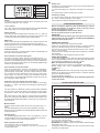
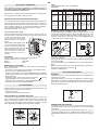
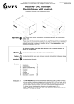
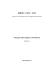
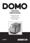
GB
Instructions booklet
mod. EKM 90410 X
EKM 90310 X
GB
GENERAL INFORMATION
RECOMENDATIONS AND PRECAUTIONS
ATTENTION:
The use of a gas cooking appliance results in the production of heat
and moisture in the room in which it is installed. Ensure that the kitchen
is well ventilated : keep natural ventilation holes open or install a
mechanical ventilation device (mechanical extractor hood).
Prolonged intensive use of the appliance may call for additional
ventilation, for example opening of a window, or more effective
ventilation, for example increasing the level of mechanical ventilation
where present.
Prior to installation, ensure that the local distribution conditions (nature
of the gas and gas pressure) and the adjustment of the appliance are
compatible.
- Before using the appliance, remember to remove the protective
plastic film present on some parts of the appliance (facia-panel,
parts in stainless steel, etc.)
- Do not use the appliance for the purpose of heating.
- When the appliance is not in use, we recommend you unplug it
from the mains electricity and shut the gas tap.
SAFEGUARDING THE ENVIRONMENT
Packaging disposal
Sort packaging into different materials (cardboard, polystyrene
etc.) and dispose of them in accordance with local waste
disposal laws.
This appliance complies with the following European Directives:
- 73/23/EEC regarding "Low Voltage".
- 89/336/EEC regarding "Electromagnetic Disturbances".
- 90/396/EEC regarding “Gas appliances”
- 89/109/EEC regarding "Materials in contact with food"
- Moreover the above mentioned Directives comply with Directive
93/68/EEC.
- This appliance must be installed in accordance with the regulations
in force and must only be used in well ventilated rooms. Consult
the instructions booklet before installing and using the appliance.
- This household appliance has been designed for cooking and it
must therefore be used for this purpose only.
IN THE EVENT OF FIRE:
• In the event of fire, immediately shut the main valve of the gas
supply, unplug the appliance from the mains. Never, under any
circumstances, pour water on burning oil.
• Do not store flammable products or aerosol containers near the
burners, and do not vaporize them near lighted burners.
This appliance is marked according to the Europeandirective
2002/96/EC on Waste Electricaland Electronic Equipment (WEEE).By
ensuring this product is disposed of correctly,you will help prevent
potential negativeconsequences for the environment and humanhealth,
which could otherwise be caused byinappropriate waste handling of
this product.
FOR YOUR SAFETY AND THAT OF YOUR CHILDREN.
• Do not store items that are attractive to children above or near the
appliance.
• Keep children well away from the appliance: bear in mind that some
parts of the appliance and the pans become dangerously hot during
use, and that they take a while to cool down.
• In order to avoid any unintentional accidents, pan handles should
be turned inwards to the rear of the cooker, not outwards into the
room or over adjacent burners.
• When cooking, do not use clothes with long, wide or flammable
sleeves; if they catch fire you may be seriously burned.
The symbol
on the product, or on thedocuments accompanying
the product, indicatesthat this appliance may not be treated
ashousehold waste. Instead it shall be handedover to the applicable
collection point for therecycling of electrical and electronic
equipment.Disposal must be carried out in accordance withlocal
environmental regulations for wastedisposal.For more detailed
information about treatment,recovery and recycling of this product,
pleasecontact your local city office, your householdwaste disposal
service or the shop where youpurchased the product.
WARNING - OVEN:
When the oven or grill are in use, accessible parts can become
very hot; keep children well away from the appliance.
- Never cook food on the very bottom of the oven.
- Carelessness in proximity of the oven door hinges can lead to injury.
- Do not let children sit down or play with the oven door. Do not use
the drop down door as a stool to reach cabinets above.
DEAR CUSTOMER,
• Carefully read these instructions before using the appliance and
keep them for future consultation.
• Keep potentially hazardous packaging (plastic bags, polystyrene
etc.) out of the reach of children.
WARRANTY
Your new appliance is covered by a warranty.
The warranty certificate is herewith enclosed. If it is missing, ask the
retailer for it, indicating date of purchase, model, and data plate
number which are printed on the data plate identifying the appliance
(fig. 9 * ).
Keep the part intended for the user, and show it upon request to the
After-sales Service, along with proof of purchase.
If you fail to do so, the after-sales service will be obliged to charge
you in full for any repair work carried out.
Original spare parts should be purchased only from our After-sales
Service and Spare Parts Authorised Centres.
INFERIOR DRAWER
Never place inflammable materials or plastic utensils in the inferior
drawer (housed below the oven).
AFTER-SALES SERVICE
Before leaving the factory, this appliance has been tested and set
up by skilled personal, in order to ensure optimum performance.
Any repair or intervention subsequently required must be carried out
with the utmost care and attention.
For this reason, we recommend you always contact the Sales Centre
or your nearest After-sales Service. Always specify the nature of the
problem and the appliance model.
2
GB
Fan oven cooking table
COOK-TOP USE
USING THE GAS BURNERS
The following symbols are found on the control panel next to each
knob:
- Circle
gas off
- Large flame
maximum setting
- Small flame
minimum setting
Dish
First courses
Lasagne
Oven-baked pasta
Creole rice
Pizza
Meat
Roast veal
Roast pork
Roast beef
Roast beef joint
Roast fillet beef (rare)
Roast lamb
Roast chicken
Roast duck
Roast goose
Roast turkey
Roast rabbit
Roast hare
Fish
Sweets (pastries)
Fruit flan
Plain sandwich cake
Sponge sandwich cake
Sponge cake
Currant cake
Buns
Strûdel
Cream slices
Apple fritters
Sponge finger pudding
Sponge finder biscuits
Toasted sandwiches
Bread
The minimum position is at the end of the anti-clockwise rotation of
the knob. Knob positions must be set between max. and min.; never
set the knobs between max. and off.
AUTOMATIC ELECTRIC IGNITION
To turn a burner on, press the knob corresponding to the selected
burner and turn it anticlockwise to the max position. Keeping the knob
pressed, the burner will automatically ignite.
In the event of a power failure, the burner can also be lit using a
match.
SAFETY VALVE
Follow the same procedure described above to ignite the burners.
In this case, however, once you have turned the knob to the open
setting, hold it pressed down for 10 seconds.
If for any reason the burner flame goes out, the safety valve
automatically shuts off the gas supply to the burner in question.
ENERGY SAVING TIPS
• The diameter of the pan bottom should be the same as that of the
burner. The burner flame must never exceed the pan’s diameter.
• Use flat-bottomed pans only.
• Whenever possible, keep a lid on the pan while cooking.
This allows you cook using less heat.
• Cook vegetables, potatoes, etc. with as little water as possible to
reduce cooking times.
BURNERS
RAPID
SEMIRAPID
AUXILIARY
TRIPLE CROWN
Temp. °C.
Minutes
Weight kg.
200-220
200-220
200-230
210-230
20-25
25-30
20-25
30-45
0,5
0,5
0,5
0,5
160-180
160-170
170-190
170-180
180-190
140-160
180
170-180
160-180
160-170
160-170
170-180
160-180
65-90
70-100
40-60
65-90
40-45
100-130
70-90
100-160
120-160
160-240
80-100
30-50
acc. to weight
1-1,2
1-1,2
1-1,2
1-1,2
1-1,5
1,5
1-1,2
1,5-2
3-3,5
5 approx.
2 approx.
2 approx.
180-200
160-180
200-220
200-230
230-250
170-180
160
180-200
180-200
170-180
150-180
230-250
200-220
40-50
35-45
40-45
25-35
30-40
40-60
25-35
20-30
18-25
30-40
50-60
7
40
MULTIFUNCTIONAL OVEN
The oven is fitted with:
• a lower heating element;
• an upper heating element;
• a circular heating element surrounding the fan.
N.B.: Always set the temperature on the thermostat knob before selecting
any of the functions.
PANS
Ø min.
Ø max
180 mm
220 mm
120 mm
200 mm
80 mm
160 mm
220 mm
260 mm
USING THE ELECTRIC OVEN
Oven thermostat knob
To obtain an oven temperature between 60°C and MAX°C, turn the knob
clockwise.
The first time the oven is used, it may give off an acrid smell, caused
by the first heating of insulating panels adhesive surrounding the oven
(heat the oven at the maximum temperature for about 30-40
minutes with closed door).
It is perfectly normal for the oven to smoke when first used; wait for
the smoke to stop before placing food into the oven.
The oven is fitted with: a grill shelf for cooking food in oven dishes
or for placing directly on the grill shelf itself, a drip-tray for cooking
sweets, biscuits, pizzas, etc., or for collecting juices and fats from
food cooked directly on the grill shelf.
Note: The following tables provide a guide for cooking some of the
most popular dishes. The cooking times recommended in these tables
are approximate. After a few attemps, we are sure that you will be
able to adjust the times to get the results you want.
60
200
17
5
0
10
225
80
m
ax
150
125
Oven function knob
It is possible to select one of the following functions turning the function
knob clockwise.
Conventional cooking table
Dish
Fish
Meat
Roast beef
Roast veal
Chicken
Duck and goose
Leg of mutton
Roast pork
Soufflés
Sweets (pastries)
Tea-cake
Sponge finger
Shortcrust pastry
Puff pastry
Fruit flan
Meringues
Quiches, etc.
Quick sponge
Buns
Temp. °C.
180-240
Minutes
acc. to size
250
200-220
200-240
220
250
250
200
30 per kg.
30 per kg.
50 about
acc. to weight
30 per kg.
60 per kg.
60 per kg.
160
160
200
250
200-220
100
220
120-140
160-180
50-60
30-50
15
15
30
60
30
60
45
Note:
All the functions mentioned above switch the oven internal light on. A
warning light on the control panel will remain lit until the temperature is
reached, after which it will light up intermittently.
Geat the oven 5 minutes before introducing the food.
Using the oven
Always use the oven with the oven door closed.
When the functions
are used, set the thermostat knob
between 180 ÷ 200°C as maximum temperature.
3
GB
ATTENTION:
The temperature shown on the control panel corresponds to the
temperature in the centre of the oven only when the functions selected
are
or
.
Fig. 3
R
P
When you turn the control knob to this position, the light will be on for
all the following operations.
F
L
G
Defrosting with fan
Ambient temperature air is distributed inside the oven, allowing you
to defrost food very quickly and without loss of protein.
TURNSPIT (mod. EKM 90410 X)
To use the turnspit follow the instructions below.
- Thread the chicken or cubes of meat for roasting on the spit L.
Ensure that it is secured properly between the two forks F and
balance it correctly to avoid unnecessary strain on the transmission
R (fig 3A).
- Rest the spit on the support G, after having fitted the opposite
end into socket P of the transmission R (fig 3A)
- Place the support G in the oven so that the bar I goes into the
socket H of the turnspit motor M (fig 3B).
- Place the drip-tray with some water under the turnspit, on the
lowest level
- Wear oven gloves to remove the spit and pull out support G.
Natural convection
Both the lower and upper heating elements operate together.
This is the traditional cooking function, which is ideal for roasting
joints, baking biscuits, making baked apples and crisping food.
This function gives excellent results when cooking on one shelf, with
the temperature set between 60 and MAX°C.
Fan oven
Both the fan and the circular heating element operate together.
The hot air, which can be set between 60 and MAX°C, is uniformly
distributed inside the oven. This function is ideal for cooking several
types of food (meat, fish), without affecting taste and smell.
It is also perfect for delicate pastries.
Fig. 3A
Fig. 3B
R
L
F
M
H
P
G
I
Medium grill (+ turnspit
according to the models)
This function is ideal for grilling small quantities of traditional food and
cooking au gratin dishes.
The thermostat knob must be set to the maximum temperature.
R
G
To operate the turnspit, turn the knob to position
(fig 3C).
Total grill (+ turnspit
according to the models)
This function is ideal for grilling traditional food and cooking au gratin
dishes.
Set the thermostat control knob to 200°C.
Fan assisted total grill (+ turnspit
according to the models)
The air is heated by the grill heating element and circulated by means
of the fan, which distributes the heat over the food.
The fan assisted grill is a perfect alternative to the turnspit. It also
gives excellent results also for large quantities of poultry, sausage
and red meat. Turn the thermostat control knob to 200°C.
Fig. 3C
INSTRUCTIONS FOR USING THE CONTROL DEVICE
MINUTES COUNTERS (Fig.4)
Turn the knob clockwise to set the desired cooking time.
The minutes minder can be adjusted from 1 to 60 minutes.
A sound signal will inform you that the chosen time is up.
Fan assisted lower heating element
The air is heated by the lower heating element and circulated by
means of the fan, which distributes the heat over the food.
This function can be used to sterilize food. Set the thermostat contol
knob between 60 and MAX°C
Fig. 4
USING THE TURNSPIT (according to the models)
“LED” PROGRAMMER (Fig. 4A)
TURNSPIT (mod. EKM 90310 X)
To use the turnspit follow the instructions below.
- Thread the chicken or cubes of meat for roasting on the spit L.
Ensure that it is secured properly between the two forks F and
balance it correctly to avoid unnecessary strain on the transmission
R (fig 3).
- Rest the spit on the support G, after having fitted the opposite
end into socket P of the transmission R (fig 3)
- Place the drip-tray with some water under the turnspit, on the
lowest level.
- Wear oven gloves to remove the spit.
To operate the turnspit, turn the knob to position
.
Features
24 hours clock with automatic timer and minute minder.
Functions
Cooking time, cooking end time, manual position, clock,
minute minder, maximum programmable time 23 hours 59 minutes.
Display
4-digit, 7-section display for cooking times and clock.
Cooking time and manual function
=
saucepan symbol
Automatic function
=
AUTO
Minutes minder
=
bell symbol
The symbols light up when the corresponding functions are selected.
4
GB
Fig. 4A
Setting error
A setting error is made if the time of day on the clock falls within the
cooking start and end times.
To correct the setting error, change the cooking time or cooking end
time.
The relays switch off when a setting error is made.
Minute minder
A
U
T
O
Cooking time
Cooking end
Manual
Decrease time
Cancelling a setting
To cancel a setting, press the cooking time button and then press
the - button until 00 00 appears on the display.
A set programme will automatically cancel on completion.
Increase time
Setting
To set, press and release the desired function, and within 5 seconds
set the time using the + and - buttons.
CARE AND MAINTENANCE
Before cleaning the appliance, turn off the mains gas tap and
unplug the appliance or disconnect power at the main circuit
breaker of the electrical system.
Do not clean appliance surfaces when still hot.
Do not use steam cleaners to clean the oven.
IMPORTANT
Periodically check the external gas connection hole and replace
it when it shows any sign of wear. Do not under any cincumstances
attempt to repair the gas hose.
+ and - buttons.
The + and - buttons increase and decrease the time respectively the
speed depending on how long the button is pressed.
Setting the time
Press any two buttons manual at the same time, and + or - button to
set the desired time. This deletes any previously set programme. The
contacts are switched off and the AUTO symbol flashes.
Manual use
When the manual button is pressed the relay contacts switch on, the
AUTO symbol switches off and the saucepan symbol lights up.
Manual operation can only be enabled after the automatic programme
is over it has been cancelled.
ENAMELLED SURFACES
Clean with a damp sponge using soap and water.
Grease can be easily removed using hot water or a specific cleansing
agent for enamelled surfaces. Do not use abrasive cleansers.
Do not leave any acid or alkaline substances (lemon juice, vinegar,
salt, etc.) on the enamel.
Clean the parts in stainless steel with specific cleansers for stainless
steel surfaces.
These detergents must be applied using a soft cloth.
GRIDS AND BURNERS
To clean the cooktop burners, remove by pulling upwards and soak
them for approximately 10 minutes in hot water with a little detergent.
After cleaning and washing them, dry them carefully.
Make sure that burner holes are not clogged.
Clean the burners once a week or more frequently if necessary.
MAKE SURE YOU HAVE ASSEMBLED THE BURNERS
CORRECTLY.
OVEN
Clean enamelled parts with a damp sponge using soap and water.
Grease can be easily removed using hot water or a specific cleansing
agent for enamelled surfaces.
Do not use abrasive cleansers.
Automatic function
Press the cooking time or end time button to switch automatically from
the manual to the automatic function.
Semi-automatic use to set cooking time
Press the cooking time button and set the desired time with + or -.
The AUTO and cooking time symbols light up continuously. The relay
switches on immediately. When the cooking end time is reached, the
relay and cooking time symbol switch off, the acoustic signal sounds
and the AUTO symbol flashes.
Semi-automatic use to set end time
Press the end time button. The time of day appears on the display.
Set the cooking end time with + button. The AUTO and cooking time
symbols light up continuously. The relay contacts switch on. When
the cooking end time is reached, the relay and the cooking time
symbol switch off. When the cooking time is finished, the AUTO
symbol flashes, the acoustic signal sounds and both the relay and
the cooking time button switch off.
Install shelves by locating them in the horizontal guide rails
on the oven walls.
Automatic use to set cooking time and end time
Press the cooking time button and select the duration of the cooking
time with + or - button. The AUTO and cooking time symbols light up
continuously.
INSTRUCTIONS FOR THE USER
895
Acoustic signal
The acoustic signal sounds at the end of a programme or of the
minutes minder function and it lasts for a maximum of 15 minutes.
To stop it, push any one of the functions buttons.
600
100
Minutes minder
Press the minute minder button and set the cooking time with + or button.
The bell symbol lights up when the minutes minder is operating
When the set time is finished, the acoustic signal sounds and the bell
symbol switches off.
910/960
1450/1500
The relay switches on. When the cooking end time button is pressed
the next cooking end time is shown on the display. Set the cooking
end time with + button. The relay and the cooking time symbol switch
off.
The symbol lights up again when the cooking start time is reached.
When the cooking time is finished, the AUTO symbol flashes, the
acoustic signal sounds and both the cooking time symbol and the
relay switch off.
850/900
OVERALL DIMENSIONS
WARNINGS
Do not use the oven door handle to move the appliance, for example
to remove it from the packaging.
The appliance is in class 1 or class 2 subclass 1.
IMPORTANT: Any adjacent furniture must be able to withstand high
temperatures (min. 90°C).
If the appliance is to be installed near units, leave the minimum gaps
specified in the table below.
Start programme and check
The programme starts 4 seconds after it has been set.
The programme can be verified at any time by pressing the
corresponding button.
5
GB
min.100 mm
"0" mm
"0" mm
min. 400 mm
min. 50 mm
min. 650 mm
min. 50 mm
The cooker must be installed by a qualified person in accordance with
the Gas Safety (Installation and Use) (Amendment) Regulations 1990
and the relevant building/I.E.E. Regulations.
Failure to install the appliance correctly could invalidate any
manufacturers warranty and lead to prosecution under the above
quoted regulations.
Provision for Ventilation
The room containing the cooker should have an air supply in accordance
with BS 5440: Part 2: 1989. The room must have an opening windows
or equivalent; some rooms may also require a permanent vent. If the
room has a volume between 5 and 10m3, it will require an air vent of
50cm2 effective area unless it has a door which opens directly to the
outside. If the room has a volume of less than 5m3, it will require an
air vent of 100cm2 effective area. If there are other fuel burning
appliances in the same room, BS 5440: Part 2: 1989 should be
consulted to determine air vent requirements. Ensure that the room
containing the cooker is well ventilated, keep natural ventilation holes
or install a mechanical ventilation device (mechanical cooker hood).
Prolonged intensive use of the appliance may call for
additionalventilation, for example opening of a window, or more
effective ventilation, for example increasing the level of mechanical
ventilation where present. This cooker is not fitted with a device for
discharging the products of combustion. Ensure that the ventilation
rules and regulations are followed. Excess steam from the oven, vents
out at the top back edge of the cooker, so make sure that the walls
behind and near the cooker are resistant to heat, steam and
condensation. Your cooker must stand on a flat surface so that when
it is in position the hob is level. When in position check that the cooker
is level by using a spirit level and adjust the 2 feet at the rear and the
2 feet at the front if necessary. It is important that the cooker is stable
and level for the overall cooking performance.
Remember that the quantity of air necessary for combustion must
never be less than 2m3/h for each kW of power (see total power in
kW on the appliance data plate fig. 9 ).
Location
Your cooker is heavy, so be careful when moving or positioning it.
Do not try to move the cooker by pulling on the doors, handles or
control panel. The cooker is designed to “slot in” between 600mm
deep cabinets, spaced approximately 1000mm apart. It can also be
used free-standing, with a cabinet to one side, in a corner setting or
with its back to a wall.
In case of installation between kitchen units, their sides must withstand
a temperature of at least 90 degrees C.
The wall behind the cooker and 450mm above and across the width
of the cooker, should be an incombustible material or easy clean
895 as ceramic tiles.
surface such
Any overhanging surface or cooker hood should be at least 650mm
(30”) above the cooker hob. We do not recommend positioning the
cooker below wall cupboards, as the heat and steam from the cooker
may cause damage to the cupboard and its contents.
The cooker may be located in a kitchen, or a bed-sitting room, but
not in a room containing a bath or shower. The cooker must not be
installed in a bed-sitting room of less than 20m3 .
LPG Models must not be installed in a room or internal space below
ground level, e.g. in a basement.
*
Gas Safety (Installation & Use) Regulations
It is the law that all gas appliances are installed by competent persons
in accordance with the current edition of the Installation & Use
Regulations. It is in your interest and that of safety to ensure
compliance with the law.
In the UK, CORGI registered installers work to safe standards of
practice.
The cooker must also be installed in accordance with BS 6172: 1990.
Failure to install the cooker correctly could invalidate the warranty
liability claims and could lead to prosecution.
The cooker is fitted with 4 legs for easy adjustment of height to suit
adjacent furniture. To assemble legs, lift the cooker up and screw the
four legs into the suitable threadings located at the corners on the
underside of the appliance ( fig 8).
OK
Gas Connection
Prior to installation, ensure that the local distribution conditions (nature
of the gas and gas pressure) and the adjustment conditions are
compatible. The adjustment conditions for this appliance are stated
on the rating plate which can be found on the inside of the front
appliance drawer.
This appliance is not designed to be connected to a combustion
products evacuation device. Particular attention should be given to
the relevant requirements regarding ventilation.
Connection to the cooker should be made with an approved appliance
flexible connection to BS 669. Models for use with LPG should be
fitted with a hose suitable for LPG and capable of withstanding 50mbar
pressure. A length of 0.9 to 1.25m is recommended. The length of
hose chosen should be such that when the cooker is in situ, the hose
does not touch the floor.
The temperature rise of areas at the rear of the cooker that are likely
to come in contact with the flexible hose do not exceed 700C.
Gas pressure may be checked on a semi-rapid hob burner. Remove
the appropriate injector and attach a test nipple. Light the other burners
and observe that the gas pressure complies with the gas standards
in force.
NO
Fig. 8
Fig. 9
CONNECTION
Certain models can be set for sypply both on the right or lefthand
side. In this case it is sufficient to reverse the position of the cad nipple
reducer. At the end make sure than there is no leakage of gas.
This appliance shall be installed in accordance whit the regulations
in force and only in a well-ventilated space. Read the instructions
before installing or using this appliance.
IMPORTANT
This cooker is supplied for use on gas specified on the data plate of
the appliance and cannot be used for any other gas without modification.
Conversion for use on other gases must only be undertaken by a
qualified person. For information for use on other gases contact your
local Service Centre.
INLET
6
STOP
GB
TAB. D
Values referred to Hs - 15°C - 1013,25mbar
Cat. II 2H3+
ELECTRICAL CONNECTION
This appliance must be installed by a qualified person in
accordance with the latest IEE Regulations and in compliance
with the manufacturer’s instructions.
TABELLA GENERALE INIETTORI
Kind of gas mbar Nozzle Burners
Power KW
Consum
N°
max. min. max.
min.
115 Rapide
3,00 0,75 286 l/h 72 l/h
NATURAL 20
97 Semi rapide 1,75 0,48 167 l/h 46 l/h
G 20
72 Auxiliary
1,00 0,33 95 l/h 31 l/h
128 Triple crown 3,30 1,30 315 l/h 124 l/h
Check that the voltage is the same as that stated on the rating plate.
The rating plate is located on the back cover.
WARNING! THIS APPLIANCE MUST BE EARTHED
BUTANE
G 30
If an fixed appliance is not equipped with supply cable and plug, the
power supply must be fitted with a disconnect switch in which the
distance between contacts permits total disconnection in accordance
with overvoltage category III, as required by installation regulations.
We recommend that the cooker circuit is rated to 13 amps.
Cable type HO5 RRF 3 X 1.5 mm2
PROPANE
G 31
28-30
37
85
65
50
93
Rapide
Semi rapide
Auxiliary
Triple crown
3,00
1,75
1,00
3,30
N°
By pass
reg.
reg.
reg.
reg.
0,75 219 g/h 55 g/h 42
0,48 128 g/h 35 g/h 31
0,33 73 g/h 24 g/h 27
1,30 241 g/h 95 g/h 60
MINIMUM FLOW ADJUSTMENT FOR COOKTOP TAPS
To adjust the minimum, proceed as follows: switch the burner on, and
turn the knob towards the minimum flow position . Remove the knob
from the tap, introduce a small screwdriver in to the tap rod (fig. 11).
Attention: in taps with security valve, the minimum adjustment screw
“Z” is placed outside the tap rod (fig. 12).
Connecting the mains cable
Open the mains terminal block cover as shown, unscrew screw “A”
the cable clamp, and loosen the screws in the mains terminal block
“L N E” which secure the three
wires of the mains cable. Fit the
cable and refit screw “A”, the cable
clamp.
Allow sufficient cable length for the
cooker to be pulled out for cleaning,
but do not let it hang lower than
50mm (2”) from the floor. The cable
can be looped if necessary, but
make sure that it is not kinked or
trapped when the cooker is in
position.
Z
Fig. 11
IMPORTANT
The wires in the mains cable are coloured as follows:
GREEN AND YELLOW........EARTH
BLUE....................................NEUTRAL
BROWN ...............................LIVE
Fig. 12
Loosen the adjustment screw in order to increase the flow or tighten
it to decrease the flow.
The proper adjustment is obtained when the flame is approximately
3 or 4 mm in length.
For butane/propane gas, the adjustment screw must be fully screwed
down.
Make sure that the flame does not go out when passing quickly from
the max. flow
to the minimum flow
.
Assemble the knob again.
REPLACING OF THE CABLE
If the cable becomes damaged or worn, replace it, observing the
following instructions:
- open the box of the supply board as shown in the diagram below;
- unscrew screw “A” that secures the cable;
- replace the cable with one of the same length and which corresponds
to the features described in the table; switch the appliance off, and
shut the gas tap;
- connect the ‘green-yellow” earth wire to the terminal “
“, leaving
it approximately 10 mm longer than the live wire;
- connect the “blue” neutral wire to the terminal marked “N”;
- connect the live wire to the terminal marked “L”.
APPLIANCE MAINTENANCE
WARNINGS
Isolate the cooker from the electricity supply before attempting to
replace the oven lamp.
The oven lamp is of a special type designed to withstand high
temperatures. To replace it, proceed as follows: remove the protective
glass (A) and replace the burnt-out bulb with one of the same type.
Re-fit the protective glass.
GAS ADJUSTMENT
Always isolate the cooker from the electricity supply, shut off the gas
supply temporarily and proceed as follows.
- change the injectors,
- adjust the minimum flow of the burners.
E 14
25 W - 230 V~
T300°C
REPLACEMENT OF COOKTOP INJECTORS
To change the cooktop injectors, proceed as follows: remove the
grids, remove burners and flame-spreaders (see fig.A), change the
injector (see fig.B) and replace it with another one suitable for the
new type of gas (see table D). Re-assemble everything in reverse
order, ensuring you position the flame-spreader correctly.
A
A
DISMANTLING THE COOKTOP
If it becomes necessary to repair or replace internal components,
proceed as follows: remove the glass lid from its position by sliding
off upwards.
Remove the grids, the burners and flame-spreaders (see fig. 13),
unscrew the visible screws “V” located on the cooktop (see fig. 14).
Dismantle the cooktop by unscrewing the 4 rear screws “A” (see fig.
15 ).
B
7
GB
For your safety
The product should only be used for its prescribed purpose, namely
for domestic cooking of foodstuffs.
Under no circumstances should any external covers be removed for
servicing or maintenance except by suitably qualified personnel.
V
Fig.14
A
TO RAISE AND TO
PUSH IN AHEAD
A
Fig. 15
GREASING THE TAPS
If a tap becomes hard to turn, grease it using specific grease designed
to withstand high temperatures. Proceed as follows: switch the
appliance off, shut the gas tap, open the cooktop and dismantle the
control panel as described in the previous paragraph. Unscrew the
two fixing screws from the burner body (see diagram) and remove
the cone.
Clean the cone and its slot using a cloth soaked with thinner. Lightly
grease the cone with the proper grease, fit it back in its slot, and turn
it several times. Remove the cone again, remove the excess grease,
making sure the gas apertures are not obstructed by residual grease.
Assemble everything carefully in reverse order, then check the
connection for leaks using soapy water.
TAP REPLACEMENT
Proceed as follows: switch the appliance off, shut the mains tap, open
the cooktop and dismantle also the control panel as described in the
previous paragraph. Unscrew screw nut D of the gas pipe supplying
the burner. Unscrew screw V that secures the tap to the bridle and
remove it (see diagram).
Note: Whenever a tap is replaced, make sure you also replace the
gasket and check the connection for leaks using soapy water (see
diagram).
D
NEVER
Never allow children near the cooker when in use as all surfaces will
become hot during and after cooking.
Never allow anyone to sit or stand on any part of the cooker.
Never heat up unopened food containers as pressure can build up
causing the container to burst.
Never store chemicals, food stuffs, pressurised containers in or on
the cooker, or in cabinets immediately above or next to the cooker.
Never fill a deep fat frying pan more than1/3 full of fat or oil and never
use a lid with this type of pan.
NEVER LEAVE PANS UNATTENDED WHILE COOKING.
Never place flammable or plastic items on or near the hob burners.
Never use proprietary spillage collectors on the hob burners.
Never use the cooker for the purpose of heating.
Never dry clothes or place other items over or near to the hob burners
or oven doors.
Never wear garments with long wide sleeves whilst cooking.
Never place flammable materials in the oven or the compartment
below the oven.
Never allow fat or oil to build up in the oven trays, grill pan or oven
base.
Never place cooking utensils or plates on the oven base.
Never grill food containing fat without using the grill rack.
Never cover the grill rack with aluminium foil.
Never place hot enamel parts in water, leave them to cool first.
Never allow vinegar, coffee, milk, saltwater, lemon or tomato juice
to remain in contact with enamel parts (inside the oven and oven
trays).
Never use abrasive cleaners or powders since these could scratch
the surface of the stainless steel and the enamel.
Tip. Montagnani - Italy - cod. 537115 0506
Fig. 13
ALWAYS
Always make sure you understand the controls before using the
cooker.
Always check that all controls on the cooker are turned off after use.
Always stand back when opening an oven door to allow heat to
disperse.
Always use dry, good quality oven gloves when removing items from
the oven.
Always take care when removing items from the oven, as they may
be dangerously hot.
Always keep the oven doors closed when the cooker is not in use.
Always place pans centrally over the burners and position them so
that the handles cannot accidentally be caught or knocked or become
heated by other burners.
Always keep the cooker clean, as a build up of grease or fat from
cooking can cause a fire.
Always allow the cooker to cool before cleaning.
Always follow the basic principles of food handling and hygiene to
prevent proliferation of bacteria.
Always keep ventilation grilles free from obstructions.
Always turn off the electricity before cleaning or replacing an oven
lamp.
15
V
7
0051