1
.0
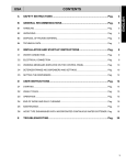
CONTENTS
A
SAFETY INSTRUCTIONS ................................................................................Pag.
4
B
GENERAL RECOMMENDATIONS ..................................................................Pag.
5
B1
HANDLING ................................................................................................................................ Pag.
5
B2
UNPACKING ............................................................................................................................. Pag.
5
B3
DISPOSAL OF PACKING MATERIAL....................................................................................... Pag.
6
B4
TECHNICAL DATA.................................................................................................................... Pag.
7
C
INSTALLATION AND START-UP INSTRUCTIONS ........................................Pag.
11
C1
WATER CONNECTION............................................................................................................. Pag.
11
C2
ELECTRICAL CONNECTION ................................................................................................... Pag.
11
C3
WARNING MESSAGES DISPLAYED ON THE CONTROL PANEL ......................................... Pag.
12
C4
DETERGENT/RINSE-AID DISPENSERS AND SETTINGS...................................................... Pag.
12
C5
SETTING THE DISPENSERS................................................................................................... Pag.
13
D
USER INSTRUCTIONS.....................................................................................Pag.
15
D1
STARTING................................................................................................................................. Pag.
15
D2
WASH CYCLES......................................................................................................................... Pag.
16
D3
OPERATION.............................................................................................................................. Pag.
16
D4
END OF WORK AND DAILY CLEANING.................................................................................. Pag.
18
D5
MAINTENANCE......................................................................................................................... Pag.
19
E
TROUBLESHOOTING ......................................................................................Pag.
22
3
ENGLISH
USA
A
SAFETY INSTRUCTIONS
To reduce the risk of fire, electrical shock, or injury when using your potwasher, please follow these basic precautions including the following:
•
Read all instructions before using your potwasher.
•
This Manual does not cover every possible condition and situation that may occur. Use common sense and caution
when installing, operating and maintaining this appliance.
•
Do not sit, stand or lean on the door or racks of a potwasher.
•
Store potwasher detergent and rinse agents in clearly marked packages with MSDS (Material Safety Data Sheets)
sheets in a safe place.
•
FOR YOUR SAFETY DO NOT STORE OR USE GASOLINE OR OTHER FLAMMABLE VAPORS AND LIQUID IN
THE VICINITY OF THIS OR ANY OTHER APPLIANCE.
•
Your potwasher uses hot water to clean and sanitize a variety of wares. Machine surfaces and wares become hot
during and immediately following normal operations. Operators should use caution when loading and unloading
wares from the machine.
•
Do not touch the heating element during or immediately after use.
•
The installation of this unit must conform to local codes or, in the absence of local codes, to all National Codes governing plumbing, sanitation, safety and good trade practices.
•
BEFORE SERVICING, DISCONNECT THE ELECTRICAL SERVICE AND PLACE A RED TAG AT THE DISCONNECT SWITCH TO INDICATE WORK IS BEING DONE ON THAT CIRCUIT.
•
NOTICE: CONTACT YOUR AUTHORIZED SERVICE COMPANY TO PERFORM MAINTENANCE AND REPAIRS.
•
NOTICE: Using any parts other than genuine factory manufactured parts relieves the manufacturer of all warranty
and liability.
•
NOTICE: Manufacturer reserves the right to change specifications at any time without notice.
•
WARNING: The equipment warranty is not valid unless the appliance is installed, started and demonstrated under
the supervision of a factory trained installer.
•
WARNING: The unit must be installed by Personnel who are qualified to work with electricity and plumbing. Improper
installation can cause injury to personnel and/or damage to the equipment. The unit must be installed in accordance
with applicable codes.
SAVE THESE INSTRUCTIONS
4
GENERAL RECOMMENDATIONS
WARNING
B1
CAREFULLY READ THE INSTALLATION OPERATING AND MAINTENANCE INSTRUCTIONS BEFORE
INSTALLING
THIS
APPLIANCE.
INCORRECT
INSTALLATION, ADAPTATIONS OR ALTERNATIONS
COULD CAUSE DAMAGE TO PROPERTY OR PERSONAL INJURY. FAILURE TO COMPLY WITH THESE
INSTRUCTIONS, ABUSE RESULTING IN DAMAGE
AND IMPROPER INSTALLATION WILL VOID WARRANTY AND RESPONSIBILITIES OF THE MANUFACTURER.
Use suitable means to move the appliance: a lift truck or
fork pallet trucks (the forks should reach more than halfway beneath the appliance).
1. Carefully read this instructions booklet, as it contains
important advice for safe installation, operation and
maintenance. Keep this booklet handy in a safe place
for future reference.
2. The installation instructons contained herein are
for the use of qualified installation and service
personnel only. Installation or service by other
than qualified personnel may result in damage to
the appliance and/or injury to the operator. FAILURE TO COMPLY WITH INSTALLATION
INSTRUCTION OR IMPROPER INTALLATION
WILL VOID WARRANTY AND RESPONSIBLITIES
OF THE MANUFACTURE.
3. The equipment warranty is not valid unless the unit is
installed, started and demonstrated under the supervision of a factory trained installer.
4. Switch off the appliance in the event of failure or malfunctioning at the main circuit breaker.
Only have the appliance repaired by an Authorized Service Center and be sure to ask for OEM original spare
parts.
NOTICE FOR SHIPPING DAMAGE
• The container should be examined for damage
before and during unloading.
• The freight carrier has assumed responsibility for its
safe transit and delivery.
• If damaged equipment is received, either apparent or
concealed, a claim must be made with the delivering
carrier. Apparent damage or loss must be noted on
the freight bill at the time of delivery.
• The freight bill must then be signed by the carrier
representative (Driver). If the bill is not signed, the
carrier may refuse the claim. The supply can supply
the necessary forms.
• A request for inspection must be made to the carrier
within 15 days if there is concealed damage or loss
that is not apparent until after the equipment is uncrated. The carrier should arrange an inspection.
• Be certain to hold all contents plus all packing material. Under no circumstances should a damaged
appliance be returned to the manufacturer without
prior notice and written authorization.
B2
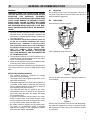
HANDLING
UNPACKING
Wear protective gloves to unpack.
Figure 1
Lift the appliance using a lift truck,
Figure 2
remove the base and position the appliance where it is
to be installed.
Figure 3
Remove the protective film and ensure that the packaging material is disposed of correctly in compliance withthe regulations in force in the country where the product
is to be used.
5
ENGLISH
B
B3
DISPOSAL OF PACKING MATERIAL
All the packaging materials are environmentally safe and
friendly. They maybe kept without fear or danger. They
may be recycled or burned in a special waste incineration plant. Recyclable plastic components are marked as
follows:
polyethylene
PE
PP
PS
polypropylene
polystyrene
foam
external wrapping film,
instruction bag.
top packaging panels,
straps.
protective surround elements.
Wood and cardboard components may be disposed of
according to local regulations in force. Appliances that
have reached the end of their service life should be suitably disposed of. The appliance should be dismantled
according to regulations in force. All metal parts are in
stainless steel (AISI 304) and are removable. Plastic
parts are marked with the symbol of the material.
6
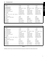
TECHNICAL DATA
MODEL
WT830M/PW1M
WT830H/PW1MH
WT850M/PW2M
Supply voltage:
208 V, 3 ph, 60 Hz 45 amp
208 V, 3 ph, 60 Hz 45 amp
208 V, 3 ph, 60 Hz 56 amp
Total Watts
14.8 kW
14.8 kW
17.5 kW
Boiler heating elements
12.0 kW
12.0 kW
12.0 kW
Tank heating elements
12.0 kW
12.0 kW
12.0 kW
Water supply pressure
7.25 - 101 psi/50 - 700 kPa
7.25 - 101 psi/50 - 700 kPa
7.25 - 101 psi/50 - 700k Pa
Water supply temperature
122°F/50°C
122°F/50°C
122°F/50°C
Water supply hardness
140 ppm/14°fH max
140 ppm/14°fH max
140 ppm/14°fH max
Rinse cycle water consumption
1.6 gallons/6.2 liters
1.6 gallons/6.2 liters
3.2 gallons/12 liters
Boiler capacity
4.8 gallons/18 liters
4.8 gallons/18 liters
4.8 gallons/18 liters
Tank capacity
25.1 gallons/95 liters
25.1 gallons/95 liters
39.6 gallons/150 liters
360/600/900 seconds
360/600/900 seconds
360/600/900 seconds
<70 dB
<70 dB
<70 dB
Standard cycle
122°F/50°C
time
with
water
supply
at
Legal noise level Leq
Minimum Supply - Circuit Ampacity
48 amp
48 amp
62 amp
Net weight
441 lb/200 kg
476 lb/216 kg
661 lb/300 kg
Shipping weight
606 lb/275 kg
628 lb/285 kg
849 lb/385 kg
Shipping width
44 1/16“ / 1120 mm
44 1/16“ / 1120 mm
70 7/8“ / 1800 mm
Shipping height
86 5/8“ / 2200 mm
94 1/2“ / 2400 mm
86 5/8“ / 2200 mm
Shipping depth
43 5/16“ /1100 mm
43 5/16“ /1100 mm
43 5/16“ /1100 mm
ENGLISH
B4
Table 1
MODEL
WT830M/PW1M
WT830H/PW1MH
WT850M/PW2M
Supply voltage:
240 V, 3 ph, 60 Hz 39 amp
240 V, 3 ph, 60 Hz 39 amp
240 V, 3 ph, 60 Hz 49 amp
Total Watts
14.8 kW
14.8 kW
17.5 kW
Boiler heating elements
12.0 kW
12.0 kW
12.0 kW
Tank heating elements
12.0 kW
12.0 kW
12.0 kW
Water supply pressure
7.25 - 101 psi/50 - 700 kPa
7.25 - 101 psi/50 - 700 kPa
7.25 - 101 psi/50 - 700k Pa
Water supply temperature
122°F/50°C
122°F/50°C
122°F/50°C
Water supply hardness
140 ppm/14°fH max
140 ppm/14°fH max
140 ppm/14°fH max
Rinse cycle water consumption
1.6 gallons/6.2 liters
1.6 gallons/6.2 liters
3.2 gallons/12 liters
Boiler capacity
4.8 gallons/18 liters
4.8 gallons/18 liters
4.8 gallons/18 liters
Tank capacity
25.1 gallons/95 liters
25.1 gallons/95 liters
39.6 gallons/150 liters
360/600/900 seconds
360/600/900 seconds
360/600/900 seconds
<70 dB
<70 dB
<70 dB
Standard cycle
122°F/50°C
time
with
water
Legal noise level Leq
supply
at
Minimum Supply - Circuit Ampacity
41 amp
41 amp
54 amp
Net weight
441 lb/200 kg
476 lb/216 kg
661 lb/300 kg
Shipping weight
606 lb/275 kg
628 lb/285 kg
849 lb/385 kg
Shipping width
44 1/16“ / 1120 mm
44 1/16“ / 1120 mm
70 7/8“ / 1800 mm
Shipping height
86 5/8“ / 2200 mm
94 1/2“ / 2400 mm
86 5/8“ / 2200 mm
Shipping depth
43 5/16“ /1100 mm
43 5/16“ /1100 mm
43 5/16“ /1100 mm
Table 2
Standard cycle time may vary should the inlet water temperature be different from that indicated above.
7
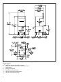
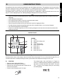
Figure 4 Installation diagram PW1M
Legend Figure 4
A - Water inlet pipe with 3/4”dia/19mm fittings
C - Outlet pipe 1 5/8” ID /40 mm (^) –11/16” ID /18 mm (*).
I - Power supply
S - Detergent connection
Q - Equipotential (Ground) screw
(^) - Only for model with free-fall drainage
(*) - Only for model with drain pump
8
ENGLISH
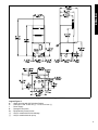
Figure 5 Installation diagram PW1MH
Legend Figure 5
A - Water inlet pipe with 3/4”dia/19mm fittings
C - Outlet pipe 1 5/8” ID /40 mm (^) –11/16” ID /18 mm (*).
I - Power supply
S - Detergent connection
Q - Equipotential (Ground) screw
(^) - Only for model with free-fall drainage
(*) - Only for model with drain pump
9
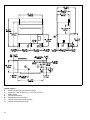
Figure 6 Installation diagram PW2M
Legend Figure 6
A - Water inlet pipe with 3/4”dia/19mm fittings
C - Outlet pipe 1 5/8” ID /40 mm (^) –11/16” ID /18 mm (*).
I - Power supply
S - Detergent connection
Q - Equipotential (Ground) screw
(^) - Only for model with free-fall drainage
(*) - Only for model with drain pump
10
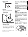
INSTALLATION AND START-UP INSTRUCTIONS
A fused disconnect switch or a main circuit breaker
(customer furnished) MUST be installed in the
electric supply line for the appliance. It is recommended that this switch/circuit breaker have
lockout/tagout capability. Before making any electrical connections to this appliance, check that the
power supply is adequate for the voltage, amperage,
and phase requirements on the rating plate.
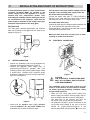
RATING PLATE
The rating plate contains identification and technical
data and is located on the right-hand side panel of the
appliance (Figure 7).
If the pressure is too high, install a suitable pressure
regulator on the incoming water supply to the unit.
On models with free-fall drainage:
connect the waste outlet pipe “C” (Figure 4/Figure 5/
Figure 6) to the main drain pipe, using a trap, or place
the outlet pipe over an “S” trap set into the floor.
On models with drain pump:
position the outlet pipe at a height anywhere between 29
1/2” to 39 3/8”/750 and 1000 mm from the floor.
Check that about 1 gallon/4 litres of water flow out of the
outlet pipe during the rinse cycle.
Make sure drain hose does not kink, pinch or twist,
resulting in a water flow restriction.
Model PW1M
PNC 9CGX 506029 05 Ser.N .123000001
AC 400V 3N
50Hz
Power Boiler
10500w
Power Tank
12000w
Power Max
22000w
Made in EU
Model PW1M
PNC 9CGX506029 05
Ser.N .123000001
C2
ELECTRICAL CONNECTION
Figure 7
C1
•
•
WATER CONNECTION
Position the potwasher and level the appliance by
adjusting the appropriate bullet feet (Figure 7).
Connect the appliance water supply pipe “A”
(Figure 4/Figure 5/Figure 6) (keeping with local
plumbing codes) to the incoming water supply. Install
a shutoff valve, Y-Strainer and a pressure gauge
between the appliance and the incoming water supply of the unit (Figure 8).
..
8..
AC
Figure 9
!
!
Figure 8
•
Check that the dynamic water supply pressure
measures between 7.25 - 101 psi/50 - 700kPa while
potwasher tank or boiler is filling with water.
20
CAUTION
THE ELECTRICAL CONNECTIONS MUST
MEET ALL NATIONAL AND ELECTRICAL
CODE REQUIREMENTS.
The installation of this unit must conform to local
codes or, in the absence of local codes, to all National Codes governing plumbing, sanitation, safety
and good trade practices.
• Check the over rating plate before making any
electric supply connections. Electric supply connections must agree with data on the unit rating plate.
• The earth wire at the terminal end must be
3/4”/20 mm (max.) longer than the phase wires.
• The appliance requires a ground connection to the
unit ground screw located at the rear of the unit
marked “Q” (Figure 4/Figure 5/Figure 6) in the
manual and marked with the symbol “ “ on the unit.
11
ENGLISH
C
The ground wire must have a cross section of AWG
6/13,3 mm2. Do not use the wiring conduit or other
piping for ground connections. If necessary, have the
electrician supply the ground wire.
WARNING
! Before servicing unit switch off power at
the main circuit breaker and place a red
tag on the breaker to indicate work is
being done on that circuit.
Power supply 208V 3ph or 240V 3ph
L1
Safety devices
• An automatic resettable thermally protectived device
incorporated in the windings of the electric pump cuts
off the electricity supply in the case of malfunctioning.
• In the event of water mains failure, a back-flow
device prevents water in the boiler from returning into
the mains.
• An overflow pipe, connected to the drainage outlet,
maintains the water in the tank at a constant level.
• On models with a drain pump, a supplementary level
control device activates if the main level control
device is faulty.
Failure to comply with safety rules and regulations
relieves the manufacturer of all liability.
L2
C3
WARNING MESSAGES DISPLAYED ON THE
CONTROL PANEL
L3
A1
Figure 10
Open the power supply terminal box and insert the jumpers provided as follows: one jumper between terminals 1
and 2, one between terminals 3 and 4 and another
between terminals 5 and 6. Using a suitable power supply cable, connect the three phases to terminals 1, 3, 5,
and the earth wire to the terminal
.
Connections provided for energy control
This appliance is designed for an external energy consumption control.
-
Check that the shutoff valve is open
Check that the water inlet filter is clean
Check the minimum main pressure is not less than
7.25 psi/50kPa
Check that the overflow pipe is inserted
-
B1
-
INSUFFICIENT DRAINAGE
Check if the overflow has been removed.
Check for obstruction on the waste outlet pipe and
the overflow aperture.
B2
11
12
NO WATER
TANK WATER LEVEL TOO HIGH
Check for obstruction on the waste outlet pipe and
the overflow aperture.
C1..C8 CALL THE AUTHORIZED SERVICE CENTER
E1..E8 CALL THE AUTHORIZED SERVICE CENTER
Figure 11
Connect the energy peak controller across terminals 11
and 12.
!
12
CAUTION
A normally open (n.o.) contact of the controller must be connected across terminals 11 and 12. When this contact closes
the boiler heating elements are disconnected. Using the potwasher in these conditions may increase the cycle time.
C4
The appliance continues to operate, but appropriate
checks by an authorized technician are recommended.
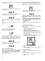
DETERGENT/RINSE-AID DISPENSERS AND
SETTINGS
All operations should be carried out with the appliance
switched on but no cycle selected.
MANUAL ACTIVATION
Whenever the detergent containers are replaced, it may
be necessary to activate the dispensers manually in
order to fill the hoses and eliminate any air.
Simultaneously press the buttons, as shown in the figures below.
1
2
1
3
DETERGENT DISPENSER
C5
2
Setting the activation time:
ENGLISH
If necessary, repeat this operation several times.
3
RINSE-AID DISPENSER
1
2
3
-
+
Initial amount of rinse-aid:
SETTING THE DISPENSERS
All operations should be carried out with the appliance
switched on, the door open and no cycle selected.
LEGEND
1
Increase
Decrease
1
2
-
+
2
3
1
2
3
-
+
3
Setting the activation time:
Confirm or select next parameter
SEQUENTIAL START
Press the indicated buttons simultaneously for 5
seconds:
Amount of detergent during the cycle:
1
2
3
1
2
3
1
2
3
-
+
Display of programming mode:
Setting the activation time:
1
2
3
Initial amount of detergent:
Amount of rinse-aid during the cycle:
1
2
3
1
2
3
13
Changing the detergent/rinse-aid type
If changing to a different detergent/rinse-aid type
(even one by the same manufacturer), you must rinse
the suction and pressure hoses with fresh water before
connecting the new detergent/rinse-aid container. Otherwise, the mixing of different types of detergent/rinse-aid
will cause crystallisation, which may result in a breakdown of the dosing pump. Failure to observe this condition will invalidate the warranty and product liability.
Setting the activation time:
1
2
-
+
3
Exit from programming mode:
1
2
3
Notes for external dispensers:
-
if dEt=181 the detergent dispenser only operates during wash pump operation; terminals 7 and 9
of the main terminal box are powered at the same
time.
-
if dEt=182 the detergent dispenser only operates during filling electrovalve operation for restoring the boiler level; terminals 7 and 9 of the main
terminal box are powered at the same time.
-
if rAi=61 the rinse-aid dispenser only operates
during filling electrovalve operation for restoring the
boiler level; terminals 8 and 9 of the main terminal
box are powered at the same time.
-
if rAi=62 the rinse-aid dispenser only operates
during wash pump operation; terminals 8 and 9 of
the main terminal box are powered at the same time.
For connections, see the wiring diagram.
Example:
Supposing that an external detergent dispenser has
been connected with a tank concentration measuring
sensor, a standard setting could be as follows:
dIn=0 the dispenser is not activated during filling of
the tank.
dEt=181 the dispenser is activated during wash
pump operation and, thanks to the concentration measured by the conduction sensor, the correct amount of
detergent is dispensed.
Suggestion: to check the effectiveness of the rinse-aid,
look at freshly washed glasses against the light. Drops of
water remaining on the glass indicate an insufficient
amount, while streaks on glass indicate an excess
amount.
14
NOTICE: This machine must be operated with an automatic detergent feeder and, if applicable, an automatic
chemical sanitizer feeder, including a visual means to
verify that detergents and sanitizers are delivered or a
visual or audible alarm to signal if detergents and sanitizers are not available for delivery to the respective
washing an sanitizing systems. Please see instructions
for electrical and plumbing connections located in this
manual and in the feeder equipment manual.
USER INSTRUCTIONS
Our appliances have been studied and optimized to give the highest performance. This appliance must be used exclusively for the purpose for which it has been designed, i.e. for washing pans with water and specific detergents. Any other
use will be considered “improper use” and will void the warranty and manufacturer liability.
This appliance will not carry out the rinse cycle should there be no supply water; it stops all functions and an error message “A1” will be displayed (also see “Warning Messages Displayed On The Control Panel”).
TIPS
•
•
•
•
•
•
•
•
Carry out a couple of cycles without pans to flush out any industrial grease which have remained in the tank
and piping.
Avoid washing decorated pans.
Do not allow pots and pans to come into contact with other metals.
Do not allow food to dry on the pots and pans.
Remove large food scraps from the pots and pans to prevent clogging the filters.
Pre-wash the pots and pans by spraying them with cold or lukewarm water, do not use any detergent.
Use automatic dispensers for the detergent.
If there is no automatic dispenser, pour a non-foaming detergent into the tank when the water has reached the
washing temperature.
CONTROL PANEL
A
B
LEGEND:
A = on/off
B = drain/self-cleaning cycle
K = display
D = “tank” indicator light
E = “boiler” indicator light
J = wash cycle 1
H = wash cycle 2
F = wash cycle 3
G = wash cycle infinite
D
K
E
J
1
2
3
H
G
F
Figure 12
The temperature shown on the display is that of the boiler if the indicator light “E” is on or of the tank if the light “D” is on.
The tank temperature is displayed during the wash cycle and the boiler temperature during the rinse cycle.
D1
•
•
•
•
STARTING
Open the water supply shutoff valve.
Switch unit on at the main circuit breaker.
Open the door and check that all the components are
in their correct position.
Close the door and press on/off “A” button.
The indicator light of the on/off button “A” (Figure 12)
comes on, indicating that the potwasher is powered and
that water is being introduced and heated. The word
“FILL” is shown on the display during the entire filling
and heating stage:
15
ENGLISH
D
If the door is opened during this stage the message
"CLOSE" will scroll on the display:
The cycle times and the temperature may be personalised (e.g. increase of the rinse time and temperature).
The cycle times should only be set by an Authorized
Service technician.
The filling and heating stage has finished when the
display shows the tank temperature:
D3
OPERATION
The filling and heating stage has finished when the display shows the tank temperature:
To display the boiler temperature during heating of the
tank, open the door and press “J” button (Figure 12).
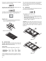
1
Supplied racks
• Tray rack: PW1M/WT830M/PW1MH/WT830MH =
1 piece; PW2M/WT850M = 2 pieces.
The appliance is then ready for use:
• Open the door.
• Pour the required amount of detergent into the tank.
• Insert the dirty pots and pans upside down on the
basket (Figure 13/ Figure 14).
• Tie pots and pans with supplied rubber bands “S” as
showed in Figure 13/ Figure 14.
CAUTION: Do not stack pots and pans one on top of
another as water must have free access to all sides of
every pot or pan. Leave a minimum gap of 4" / 101 mm
between pans and the edge of the rack (Figure 13/
Figure 14).
S
•
Basket for pots and pans.
10 4”
1m
m
4” m
1m
10
4” m
1m
10
10 4”
1m
m
Figure 13
D2
WASH CYCLES
S
The wash cycle includes one wash with hot water and
detergent (158°F/70°C min.) and one rinse with hot
water and rinse-aid (183°F/84°C min.).
Table of times
Standard cycle time with supply water at 122°F/50°C.
PW1M/WT830M
PW1MH/WT830MH
PW2M/WT850M
I
II
III
IV
360 sec
360 sec
360 sec
600 sec
600 sec
600 sec
900 sec
900 sec
900 sec
INFINITE
INFINITE
INFINITE
A device lengthens the cycle time if the water in the boiler has not reached the minimum temperature for correct
rinsing.
16
10 4”
1m
m
4” m
1m
10
4” m
1m
10
10 4”
1m
m
Figure 14
- Cycle II (recommended)
For normally dirty pots and pans: press “H” button
(Figure 12) (see table of times).
2
- Cycle III
For very dirty pots and pans: press “F” button (Figure 12)
(see table of times).
3
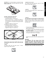
Figure 15
Increase / decrease the wash force
To wash lightweight pots and pans:
- unscrew the wing nut “X” (Figure 16);
- push the relief valve “Y” (Figure 16) inwards to
reduce pressure in the lower wash arm and increase
it in the upper arm, so that the pots and pans remain
in position;
- retighten the wing nut “X” (Figure 16).
To wash large, heavy pots and pans:
- unscrew the wing nut “X” (Figure 16);
- take out the relief valve “Y” (Figure 16);
- retighten the wing nut “X” (Figure 16).
- Cycle IV
For particularly dirty pots and pans with dried food residue, pans with a special shape or for other specific
needs of the user: press “G” button (Figure 12), which
initiates a continuous wash until the operator selects an
automatic cycle.
•
•
•
To stop the wash cycle, just press the selected cycle
button or open the door.
To continue the wash cycle, just press the selected
cycle button or close the door. The cycle starts again
from where it stopped.
At the end of the wash, the potwasher emits a series
of beeps and “END” blinks on the display:
X
Y
Figure 16
Close the door and select the suitable wash cycle; the
corresponding indicator light comes on and the wash
cycle starts:
- Cycle I
For lightly soiled pots and pans: press “J” button
(Figure 12) (see table of times).
lift the door and remove the rack containing the clean
pans.
WARNING
The appliance will not remove burnt food
deposits from pans. Pans with burnt-on food
deposits should be cleaned manually using
detergent before putting them in the potwasher.
Change the water in the tank at least twice a day.
1
17
ENGLISH
CAUTION: Do not allow handles to protrude through
bottom of rack, they may block wash and rinse arms
rotation (Figure 15).
D4
END OF WORK AND DAILY CLEANING
The appliance is designed to carry out an automatic
cleaning cycle to help flush out any residues and to
guarantee greater health and hygiene:
• Open the door and take out the rack containing the
clean pans.
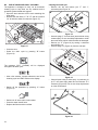
• Remove the tank filters “C”-”D”-”E” and the overflow
“W” to drain the water from the tank (Figure 17).
Cleaning the nozzle jets
• Remove the top and bottom jets “F” and “I”,
unscrewing the ring nut “H”.
H
L
I
F
E
Figure 18
D
W
C
Figure 17
•
•
•
•
•
Unscrew plugs “L” from the rinse jets and clean using
a water spray. Do not use sharp implements to clean
the nozzle holes, which could otherwise be damaged.
Remove jet “P” (Figure 19) by turning it clockwise
and pulling it out.
Unscrew plugs “R” (Figure 19) from the side jets.
Close the door.
Select the drain cycle by pressing “B” button
(Figure 12).
R
P
R
The message "CLE" ("CLEAN") will be displayed
throughout the drain cycle:
•
After a few minutes, 3 beeps indicate the end of the
cleaning cycle and “END” blinks on the display:
Figure 19
•
•
Switch off the potwasher by pressing “A” button
(Figure 12).
Clean all parts using a water spray. In particular, for
jet “P” use warm soapy water and a soft brush “Z” if
necessary (Figure 20). Do not use sharp implements
to clean nozzle holes.
Z
P
Z
Z
•
•
•
Switch unit off at the main circuit breaker.
Close the water shutoff valve.
Replace the filters and the overflow.
Z
Figure 20
18
M
Figure 21
Clean the tank
• Open the door for access to the tank (Figure 22):
- lift the lever “S” and pull the door outwards;
- gently lower the door.
• Clean the tank using a water spray to flush waste out
through the drain outlet.
S
S
S
U
Figure 22
Carry out the above operations in the reverse order to
re-assemble all the previously disassembled parts.
• Replace the door (Figure 22):
- Lift the door as far as movement permits (horizontal).
- gently push the door inwards to prevent it from tilting.
- Insert the levers “U” into their seats and push the
door until the slide blocks are no longer visible. Operations have been accomplished correctly if the
actual door closes properly.
• Close the door.
Cleaning the exterior surfaces
Before carrying out any cleaning operations, turn off the
power at the main circuit breaker.
Clean the stainless steel surfaces using warm soapy
water; never use detergents containing abrasive substances nor steel scrapers, common wire wool, brushes
or scrapers; rinse thoroughly using a wet cloth and carefully wipe dry.
Clean the control panel using a soft damp cloth and a
neutral detergent if necessary.
Do not wash the appliance using direct or high-pressure
water jets. To reduce the emission of pollutants into the
environment, clean the appliance (externally and where
necessary internally) with products having a biodegradability of over 90%.
Leave the door opened whenever the appliance is not in
use.
D5
MAINTENANCE
DELIMING
WARNING:
DELIMING
SOLUTION,
RINSE
AGENTS OR ANY OTHER KIND OF ACID MUST
NOT COME IN CONTACT WITH BLEACH OR
RINSE SOLUTION CONTAINING BLEACH USED
IN CHEMICAL-SANITIZING MACHINES. MIXING
MAY CAUSE HAZARDOUS GAS TO FORM. THIS
ENTIRE PROCEDURE MUST BE FOLLOWED
STEP BY STEP FOR SAFE AND SATISFACTORY
RESULTS.
DELIME THE POTWASHER ON A REGULAR BASIS
AS REQUIRED. The regurarity will depend on mineral
content of the supply water. Deliming should be done
when you can see clear signs of lime deposits (a white,
chalky substance) on the inside walls and on the wash
arms. If deliming is necessary, a deliming agent should
be used for best results.
Step 1 - Discarge tank dirty water
Open the door and remove any baskets that are in
chamber.
Remove tank filters “C”-”D”-”E” and overflow “W”
(Figure 23).
E
D
W
C
Figure 23
19
ENGLISH
Cleaning the pump filter
• Remove the pump filter “M” and clean any food trapped in filter.
Close the door and select the drain cycle by pressing the
“B” button (Figure 12).
Step 4 - Start the wash cycle and discarge the tank
Close the door and start the Cycle III by pressing “F”
button (Figure 12). The wash cycle duration is 6 minutes.
3
The message “CLE” ("CLEAN") will be displayed throughout the drain cycle.
At the end of the cycle the potwasher emits a series of
beeps and “END” blinks on the display.
After a few minutes, 3 beeps indicate the end of the cleaning cycle and “END” blinks on the display:
At the end of drain cycle, Open the door, replace the
tank filters “C”-”D”-”E”, the overflow “W” and close the
door.
Switch off the potwasher by pressing “A” button
(Figure 12)
Step 2 - Filling tank and heating water
Press on/off “A” button (Figure 12).
The indicator light of the on/off button “A” comes on, indicating the potwasher is powered and the water is being
introduced and heated. The word “FILL” scrolls across
display during the entire filling and heating stage.
CAUTION: observe chemicals producers instructions handling appliance where chemicals have
been used.
CAUTION: do not allow the deliming agent to remain
in the machine longer than recommended by the
deliming agent supplier.
7. Repeat the step 1.
To delime the boiler, call your authorized service company.
Prolonged period of inactivity
If the potwasher is not to be used for a long time, proceed as follows:
• Close the water supply shutoff valve.
• Completely drain the tank.
• Remove and carefully clean the filters.
• Completely drain the incorporated dispenser hoses,
removing them from the containers. Repeat the procedure described in the paragraph “Manual activation” at least 3 times.
• Completely drain the boiler by simultaneously pressing the buttons as shown in the figure.
1
2
3
The filling and heating stage has finished when the
display shows the tank temperature:
Step 3 - Pour the deliming agent
Open the door, pour the required amount of deliming
agent regarding agent concentration suggested by agent
supplier for 25.1 gallons/95 liters (for PW1M/WT830M/
PW1MH/WT830MH) or 39.6 gallons/150 liters (for
PW2M/WT850M) of water.
A buzzer indicates completion of drainage.
• Spread a thin film of petroleum jelly over all the stainless steel surfaces.
Preventive maintenance
The preventive maintenance message “CALL” may be
activated.
Upon reaching the set number of cycles (e.g. 20000),
appears on the display.
20
ENGLISH
This message advises calling a qualified authorized service technician for a general check-up on of the state of
the appliance.
NOTICE: CONTACT YOUR AUTHORIZED SERVICE
COMPANY TO PERFORM MAINTENACE AND
REPAIRS.
NOTICE: Using any parts other than genuine factory
manufactured parts relieves the manufacturer of all warranty and liability.
NOTICE: Manufacturer reserves the right to change specifications at any time without notice.
WARNING: The equipment warranty is not valid unless
the appliance is installed, started and demonstrated
under the supervision of factory trained installer.
WARNING: The unit must be installed by Personnel who
are qualified to work with electricity and plumbing.
Improper installation can cause injury to personnel
and/or damage to the equipment. The unit must be
installed in accordance with applicable codes.
21
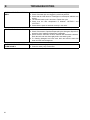
E
TROUBLESHOOTING
POTWASHER DOES NOT WASH
WELL
1. Check if the suction filter is dirty, if so clean it thoroughly.
2. Check if the wash jets are clogged by solid food particles.
3. Check that the initial amount of detergent or subsequent additions are
correct.
4. The selected wash cycle is too short. Repeat the cycle.
5. Check that the tank temperature is between 149°F/65°C and
158°F/70°C.
6. Check that the pans are stacked correctly in the racks.
EXCESSIVE FOAM IN THE TANK
1. Check that the wash water temperature is not less than 149°F/65°C.
2. Check if the amount of product dispensed by the detergent dispenser is
excessive (see “setting the dispensers” paragraph).
3. Ensure that the tank has not been cleaned with unsuitable cleaners.
Drain the tank and rinse thoroughly before new wash cycles.
4. If a foaming detergent has been used, drain and refill the tank with
water until the foam disappears.
THE WASH OR RINSE ARMS
TURN SLOWLY
1. Remove and thoroughly clean the arms.
2. Clean the wash pump suction filter.
22