1
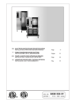
- GAS STEAM/CONVECTION OVENS
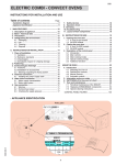
INSTALLATION, OPERATION AND MAINTENANCE
Page
- FORNI CONVEZIONE/VAPORE A GAS
INSTALLAZIONE, USO E MANUTENZIONE
Pagina
33
CDN
- FOURS À CONVECTION/VAPEUR À GAZ
INSTALLATION, UTILISATION ET ENTRETIEN
Page
57
ES
- HORNOS DE CONVECCIÓN/VAPOR DE GAS
INSTALACIÓN, USO Y MANTENIMIENTO
Pág.
81
USA
IT
DOC. NO.
EDITION 1
From the Electrolux Group
9
5938 036 01
E-Z-A 0802
LA-LC
SAFETY INSTRUCTIONS
USA
Do not store or use gasoline or other flammable vapors or liquids in the vicinity of this or any other appliance.
WARNING: Improper installation, adjustment, alteration, service or maintenance can cause property damage,
injury or death. Read the installation, operating and maintenance instructions thoroughly before installing or
servicing this equipment.
Danger! Explosion hazard.
In the event a gas odor is detected, shut down equipment at the main shut-off valve. Immediatly call the emergency phone number
of your gas supplier.
Read each section of this manual before installing and operating.
PER LA VOSTRA SICUREZZA
IT
Non immagazzinare o usare benzina o altri materiali infiammabili o liquidi nelle vicinanze di questa o qualsiasi
altra apparecchiatura.
AVVERTENZA:
Installazione impropria, adattamenti, modifiche o manutenzione possono causare danni alla
proprieta` o morte. Leggere attentamente le istruzioni per l'installazione, il funzionamento e la manutenzione prima di
installare questa apparecchatura.
Pericolo! Pericolo di esplosione.
Nel caso in cui venga avvertito odore di gas spegnere l'apparecchiatura chiudendo la valvola principale a monte della stessa. Immediatamente
telefonare al numero d'emergenza del vostro fornitore di gas.
Leggere tutte le parti di questo manuale prima di installare o mettere in funzione l'apparecchiatura.
POUR VOTRE SECURITE
CDN
Il ne faut pas emmagasiner ou utiliser l’essence ou d’autres matériaux inflammables ou liquides à côté de cet
appareil ou d’autres appareils.
AVERTISSEMENT:
L’installation, l’adaptation, la modification et l’entretien inadéquats peuvent causer des
dommages aux structures ou aux personnes et la mort. Lire attentivement les instructions d’installation, de fonctionnement
et d’entretien avant d’installer cet appareil.
Danger! Danger d’explosion.
Si l’on sent l’odeur de gaz, arrêter l’appareil en fermant la soupape principale en amont. Téléphoner immédiatement au numéro
d’urgence de votre fournisseur de gaz.
Lire toutes les parties de ce mode d’emploi avant d’installer ou mettre en fonction l’appareil.
PARA SALVAGUARDAR VUESTRA SEGURIDAD
ES
No almacenar o utilizar gasolina u otros materiales inflamables o líquidos cerca de este u otros aparatos.
ADVERTENCIA: Una
instalación indacuada, lo mismo que modificaciones y operaciones de mantenimiento
incorrectas pueden causar daños a la estructura y a las personas y provocar la muerte. Antes de instalar el aparato leer con
mucha atención las instrucciones de la instalación, del funcionamiento y del mantenimiento.
Peligro! Peligro de explosión.
En el caso que se sienta olor de gas, apagar inmediatamente el aparato cerrando la válvula principal colocada aguas arriba de
la misma. Llamar inmediatamente el número de teléfono de emergencia de la compañía erogadora del gas.
USA
IT
CDN
ES
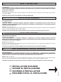
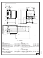
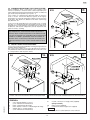
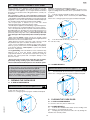
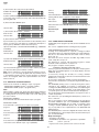
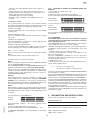
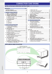
INSTALLATION DIAGRAM
SCHEMI DI INSTALLAZIONE
SCHEMAS D'INSTALLATION
ESQUEMA PARA LA INSTALACIÓN
2
5938 036 01
Leer todas las partes de este manual antes de llevar a cabo la instalación o de poner en marcha el aparato.
11
"
32
898 mm
35
7
"
32
920 mm
36
3
"
16
335 mm
13
5
1
"
8
308 mm
5
"
16
135 mm
2
12
3
5
"
16
84 mm
3
"
4
70 mm
7
"
8
200 mm
Ø 7
27
"
32
580 mm
22
5
"
16
1735 mm
68
5
"
16
440 mm
17
8
7
2 "
8
73 mm
1
"
4
159 mm
15
62
"
16
1598.5 mm
11
"
16
221 mm
6
I
9
"
32
1480 mm
58
4
17
"
32
115 mm
29
1
"
2
775 mm
30
3
6
"
32
155 mm
5
3
"
16
741.5 mm
H
C
19
"
32
142 mm
(A ^)
(B ^) B
3
C B D
(A ^) (A ^)
(B ^)
N
(A ^)
(B ^)
I
H
1
"
8
130 mm
5
13
"
16
935 mm
36
B (C ^)
15
"
16
100 mm
C
5
"
16
440 mm
17
1
"
4
159 mm
6
2
2
7
"
8
73 mm
5
"
32
55 mm
(A ^)
2
7
"
8
73 mm
8
D (A ^)
N (B ^)
I
5
"
16
516 mm
20
11
"
16
221 mm
27
"
32
580 mm
22
B (C ^)
23
"
32
1390 mm
54
H
17
4
"
32
115 mm
11
"
16
500 mm
19
cod. 597846800
3
15
"
16
100 mm
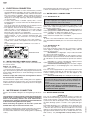
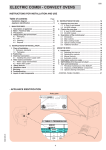
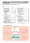
Mod.:
6 GN 1/1
USA
H - Gas connection
I - Power supply cable inlet
B - Water supply connection (0.5- 5 °F)
C - Water drain connection
N - Steam condens. water connection
D - Overflow drain pipe (AIR-BREAK)
( ^) FUNCTIONAL LEVEL
CDN
ø1/2" NPT gasline H - Entée gaz
I - Entrée câble électrique
ø3/4" NPT gasline B - Entrée eau (0,5 - 5 °F)
ø1"1/4 NPT gasline C - Collecteur évacuation eau
ø3/4" NPT gasline N - Entrée eau Conden.vapeurs
D - Évacuation de secours (AIR-BREAK)
(Do not connect)
( ^) NIVEAU FONCTIONNEL
5938 036 01
IT
H - Attacco gas
I - Entrata cavo elettrico
B - Attacco alim. acqua (0,5 - 5 °F)
C - Collettore scarico acqua
N - Attacco acqua Conden. fumane
D - Scarico di sicurezza (AIR-BREAK)
( ^) LIVELLO FUNZIONALE
ø1/2" NPT gasline
ø3/4" NPT gasline
ø1"1/4 NPT gasline
ø3/4" NPT gasline
(Ne pas raccorder)
ES
ø1/2" NPT gasline H - Conexión de gas
I - Ingreso cable eléctrico
ø3/4" NPT gasline B - Conexión de agua (0,5 - 5 °F)
ø1"1/4 NPT gasline C - Colector del desagüe
ø3/4" NPT gasline N - Entrada del agua de condensación
(Non collegare)
D - Desagüe de seguridad (AIR-BREAK)
( ^) NIVEL FUNCIONAL
ø1/2" NPT gasline
ø3/4" NPT gasline
ø1"1/4 NPT gasline
ø3/4" NPT gasline
(No conectar)
1a
3
9
"
16
1208 mm
47
11
"
32
364 mm
14
3
"
16
335 mm
13
7
"
8
200 mm
42 "
1067 mm
Ø 7
3
19
"
32
91 mm
5
5
"
16
135 mm
2
3
"
4
70 mm
13
28
"
16
732 mm
27
22
"
32
580 mm
1
"
4
362 mm
14
27
"
32
301 mm
11
15
"
32
62.5 mm
2
4
21
"
32
118 mm
23
5
"
32
145 mm
5
I
H
1
"
2
775 mm
30
5
29
9
"
62
"
58
"
16
32
32
1735 mm 1598 mm 1480 mm
1
"
8
130 mm
5
3
"
16
741 mm
29
C B
C
D
(A ^) (A ^)
(B ^)
68
N
(A ^)
(B ^)
I
H
13
"
16
935 mm
36
B (C ^)
23
"
32
145 mm
C
3
1
"
16
77.5 mm
3
1
3
"
16
77.5 mm
15
"
32
62.5 mm
2
4
21
"
32
118 mm
15
"
16
100 mm
27
"
32
301 mm
11
1
"
4
362 mm
14
27
"
32
580 mm
22
5
"
16
668 mm
26
13
"
16
732 mm
28
17
"
32
1715 mm
67
(A ^)
B (B ^)
D (A ^)
(A ^)
N (B ^)
I
B (C ^)
H
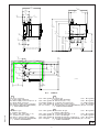
cod. 597847800
3
15
"
16
100 mm
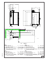
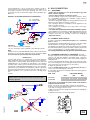
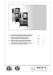
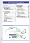
Mod.:
6 GN 2/1
USA
H - Gas connection
I - Power supply cable inlet
B - Water supply connection (0.5- 5 °F)
C - Water drain connection
N - Steam condens. water connection
D - Overflow drain pipe (AIR-BREAK)
( ^) FUNCTIONAL LEVEL
CDN
ø1/2" NPT gasline H - Entée gaz
I - Entrée câble électrique
ø3/4" NPT gasline B - Entrée eau (0,5 - 5 °F)
ø1"1/4 NPT gasline C - Collecteur évacuation eau
ø3/4" NPT gasline N - Entrée eau Conden.vapeurs
D - Évacuation de secours (AIR-BREAK)
(Do not connect)
( ^) NIVEAU FONCTIONNEL
IT
H - Attacco gas
I - Entrata cavo elettrico
B - Attacco alim. acqua (0,5 - 5 °F)
C - Collettore scarico acqua
N - Attacco acqua Conden. fumane
D - Scarico di sicurezza (AIR-BREAK)
( ^) LIVELLO FUNZIONALE
ø1/2" NPT gasline
ø3/4" NPT gasline
ø1"1/4 NPT gasline
ø3/4" NPT gasline
(Ne pas raccorder)
ES
ø1/2" NPT gasline H - Conexión de gas
I - Ingreso cable eléctrico
ø3/4" NPT gasline B - Conexión de agua (0,5 - 5 °F)
ø1"1/4 NPT gasline C - Colector del desagüe
ø3/4" NPT gasline N - Entrada del agua de condensación
(Non collegare)
D - Desagüe de seguridad (AIR-BREAK)
( ^) NIVEL FUNCIONAL
ø1/2" NPT gasline
ø3/4" NPT gasline
ø1"1/4 NPT gasline
ø3/4" NPT gasline
(No conectar)
1b
4
5938 036 01
11
"
16
500 mm
19
11
"
32
898 mm
35
7
"
32
920 mm
36
3
"
16
335 mm
13
5
1
12 "
8
308 mm
3
5
"
16
84 mm
5
"
16
135 mm
2
3
"
4
70 mm
7
"
8
200 mm
Ø 7
5
"
32
1985 mm
78
27
"
32
580 mm
22
5
"
16
440 mm
17
25
72
"
32
1848.5 mm
8
1
"
4
159 mm
11
"
16
221 mm
6
2
4
7
"
8
73 mm
I
17
"
32
115 mm
19
5
"
32
142 mm
5
1
"
8
1730 mm
68
3
"
16
741.5 mm
H
29
1
"
2
775 mm
30
C
19
"
32
142 mm
(A ^)
(B ^) B
3
C B D
(A ^) (A ^)
(B ^)
N
(A ^)
(B ^)
I
H
1
"
8
130 mm
5
13
"
16
935 mm
36
B (C ^)
15
"
16
100 mm
C
5
"
16
440 mm
17
1
"
4
159 mm
6
2
2
7
"
8
73 mm
5
"
32
55 mm
(A ^)
2
7
"
8
73 mm
8
D (A ^)
N (B ^)
I
5
"
16
516 mm
20
11
"
16
221 mm
27
"
32
580 mm
22
B (C ^)
23
"
32
1390 mm
54
H
17
4
"
32
115 mm
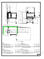
cod. 597847300
11
"
16
500 mm
19
3
15
"
16
100 mm
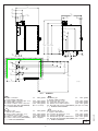
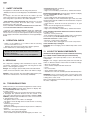
Mod. :
10 GN 1/1
USA
H - Gas connection
I - Power supply cable inlet
B - Water supply connection (0.5- 5 °F)
C - Water drain connection
N - Steam condens. water connection
D - Overflow drain pipe (AIR-BREAK)
( ^) FUNCTIONAL LEVEL
CDN
ø1/2" NPT gasline
ø3/4" NPT gasline
ø1"1/4 NPT gasline
ø3/4" NPT gasline
(Do not connect)
5938 036 01
IT
H - Attacco gas
I - Entrata cavo elettrico
B - Attacco alim. acqua (0,5 - 5 °F)
C - Collettore scarico acqua
N - Attacco acqua Conden. fumane
D - Scarico di sicurezza (AIR-BREAK)
( ^) LIVELLO FUNZIONALE
H - Entée gaz
I - Entrée câble électrique
B - Entrée eau (0,5 - 5 °F)
C - Collecteur évacuation eau
N - Entrée eau Conden.vapeurs
D - Évacuation de secours (AIR-BREAK)
( ^) NIVEAU FONCTIONNEL
ø1/2" NPT gasline
ø3/4" NPT gasline
ø1"1/4 NPT gasline
ø3/4" NPT gasline
(Ne pas raccorder)
ES
ø1/2" NPT gasline
ø3/4" NPT gasline
ø1"1/4 NPT gasline
ø3/4" NPT gasline
(Non collegare)
5
H - Conexión de gas
I - Ingreso cable eléctrico
B - Conexión de agua (0,5 - 5 °F)
C - Colector del desagüe
N - Entrada del agua de condensación
D - Desagüe de seguridad (AIR-BREAK)
( ^) NIVEL FUNCIONAL
ø1/2" NPT gasline
ø3/4" NPT gasline
ø1"1/4 NPT gasline
ø3/4" NPT gasline
(No conectar)
1c
9
"
16
1208 mm
47
11
"
32
364 mm
14
3
"
16
335 mm
13
7
"
8
200 mm
42 "
1067 mm
Ø 7
3
19
"
32
91 mm
5
5
"
16
135 mm
2
3
"
4
70 mm
U
P
13
"
16
732 mm
28
27
22
"
32
580 mm
1
14 "
4
362 mm
27
"
32
301 mm
11
15
2
"
32
62.5 mm
4
21
"
32
118 mm
23
5
"
32
145 mm
5
I
5
"
32
1985 mm
H
78
3
"
4
1848 mm
72
1
"
8
1730 mm
68
1
"
2
775 mm
30
1
"
8
130 mm
5
3
"
16
741 mm
29
C B D
N
(A ^) (A ^) (A ^)
(B ^)
(B ^)
C
I
H
13
"
16
935 mm
36
B (C ^)
23
"
32
145 mm
C
3
1
"
16
77.5 mm
3
1
"
16
77.5 mm
3
15
"
32
62.5 mm
2
21
4
"
32
118 mm
15
"
16
100 mm
27
"
32
301 mm
11
1
"
4
362 mm
14
27
"
32
580 mm
22
5
"
16
668 mm
26
13
"
16
732 mm
28
17
"
32
1715 mm
67
(A ^)
B (B ^)
D (A ^)
(A ^)
N (B ^)
I
B (C ^)
H
11
"
16
500 mm
19
3
15
"
16
100 mm
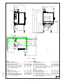
cod. 597848300
Mod.:
10 GN 2/1
USA
CDN
ø1/2" NPT gasline
ø3/4" NPT gasline
ø1"1/4 NPT gasline
ø3/4" NPT gasline
(Do not connect)
IT
H - Attacco gas
I - Entrata cavo elettrico
B - Attacco alim. acqua (0,5 - 5 °F)
C - Collettore scarico acqua
N - Attacco acqua Conden. fumane
D - Scarico di sicurezza (AIR-BREAK)
( ^) LIVELLO FUNZIONALE
H - Entée gaz
I - Entrée câble électrique
B - Entrée eau (0,5 - 5 °F)
C - Collecteur évacuation eau
N - Entrée eau Conden.vapeurs
D - Évacuation de secours (AIR-BREAK)
( ^) NIVEAU FONCTIONNEL
ø1/2" NPT gasline
ø3/4" NPT gasline
ø1"1/4 NPT gasline
ø3/4" NPT gasline
(Ne pas raccorder)
ES
ø1/2" NPT gasline
ø3/4" NPT gasline
ø1"1/4 NPT gasline
ø3/4" NPT gasline
(Non collegare)
6
H - Conexión de gas
I - Ingreso cable eléctrico
B - Conexión de agua (0,5 - 5 °F)
C - Colector del desagüe
N - Entrada del agua de condensación
D - Desagüe de seguridad (AIR-BREAK)
( ^) NIVEL FUNCIONAL
ø1/2" NPT gasline
ø3/4" NPT gasline
ø1"1/4 NPT gasline
ø3/4" NPT gasline
(No conectar)
1d
5938 036 01
H - Gas connection
I - Power supply cable inlet
B - Water supply connection (0.5- 5 °F)
C - Water drain connection
N - Steam condens. water connection
D - Overflow drain pipe (AIR-BREAK)
( ^) FUNCTIONAL LEVEL
1
"
8
994 mm
39
3
"
32
358 mm
14
3
"
16
335 mm
13
15
"
32
926 mm
36
7
"
8
200 mm
Ø 7
21
3
"
32
93 mm
5
5
"
16
135 mm
2
3
"
4
70 mm
22 "
559 mm
13
"
32
315 mm
12
9
8
7
"
32
234 mm
7
"
32
209 mm
1
21
1
"
70
"
66
"
16
32
32
1932 mm 1795 mm 1677 mm
76
H
7
6
15
"
16
176 mm
3
"
32
180 mm
8
C
C
3
15
"
16
100 mm
B
D
N
I
(A ^) (A ^) (A ^)
(B ^)
(B ^)
1
"
16
205 mm
B (C ^)
C
(A ^)
(B ^) B
8
29
2
"
32
74 mm
2
15
"
32
63 mm
6
2
D (A ^)
(A ^)
N (B ^)
15
"
16
176 mm
5
"
16
59 mm
7
"
32
13
12
"
32
234 mm
315 mm
1
"
16
586 mm
23
B (C ^)
I
23
"
32
1466 mm
57
3
23
"
32
145 mm
15
"
16
100 mm
Mod.:
cod. 597848800
20 GN 1/1
USA
H - Gas connection
I - Power supply cable inlet
B - Water supply connection (0.5- 5 °F)
C - Water drain connection
N - Steam condens. water connection
D - Overflow drain pipe (AIR-BREAK)
( ^) FUNCTIONAL LEVEL
CDN
ø1"
NPT gasline
H - Entée gaz
I - Entrée câble électrique
B - Entrée eau (0,5 - 5 °F)
C - Collecteur évacuation eau
N - Entrée eau Conden.vapeurs
D - Évacuation de secours (AIR-BREAK)
( ^) NIVEAU FONCTIONNEL
ø3/4" NPT gasline
ø1"1/4 NPT gasline
ø3/4" NPT gasline
(Do not connect)
IT
5938 036 01
9
22 "
559 mm
H
5
11
19
"
16
500 mm
7
"
32
209 mm
H - Attacco gas
I - Entrata cavo elettrico
B - Attacco alim. acqua (0,5 - 5 °F)
C - Collettore scarico acqua
N - Attacco acqua Conden. fumane
D - Scarico di sicurezza (AIR-BREAK)
( ^) LIVELLO FUNZIONALE
ø1"
NPT gasline
ø3/4" NPT gasline
ø1"1/4 NPT gasline
ø3/4" NPT gasline
(Ne pas raccorder)
ES
ø1"
NPT gasline
H - Conexión de gas
I - Ingreso cable eléctrico
B - Conexión de agua (0,5 - 5 °F)
C - Colector del desagüe
N - Entrada del agua de condensación
D - Desagüe de seguridad (AIR-BREAK)
( ^) NIVEL FUNCIONAL
ø3/4" NPT gasline
ø1"1/4 NPT gasline
ø3/4" NPT gasline
(Non collegare)
ø1"
NPT gasline
ø3/4" NPT gasline
ø1"1/4 NPT gasline
ø3/4" NPT gasline
(No conectar)
1e
7
13
"
16
1240 mm
48
9
"
32
363 mm
14
3
"
16
335 mm
13
15
"
32
1079 mm
42
7
"
8
200 mm
Ø 7
3
3 "
4
95 mm
5
5
"
16
135 mm
2
3
"
4
70 mm
25
"
32
731 mm
28
19
"
32
371 mm
14
1
"
8
308 mm
12
9
7
"
16
240 mm
1
21
1
"
70
"
66
"
16
32
32
1932 mm 1795 mm 1677 mm
76
7
6
15
"
32
164 mm
3
"
32
180 mm
8
C
3
D
C B
(A ^) (A ^)
(B ^)
15
"
16
100 mm
N
(A ^)
(B ^)
(A ^)
(B ^) B
2
9
5
"
16
59 mm
D (A ^)
(A ^)
N (B ^)
1
"
8
54 mm
2
6
7
"
16
62 mm
7
"
16
240 mm
23 "
32
628 mm
1
"
8
19
308 mm 14 32 "
371 mm
12
24
25
"
32
731 mm
28
B (C ^)
I
17
"
32
1766 mm
69
3
11
"
16
500 mm
1
"
16
205 mm
H
15
"
32
164 mm
19
I
B (C ^)
C
2
H
7
5
"
32
182 mm
15
"
16
100 mm
cod. 597849300
20 GN 2/1
Mod.:
USA
CDN
ø1"
NPT gasline
ø3/4" NPT gasline
ø1"1/4 NPT gasline
ø3/4" NPT gasline
(Do not connect)
IT
H - Attacco gas
I - Entrata cavo elettrico
B - Attacco alim. acqua (0,5 - 5 °F)
C - Collettore scarico acqua
N - Attacco acqua Conden. fumane
D - Scarico di sicurezza (AIR-BREAK)
( ^) LIVELLO FUNZIONALE
H - Entée gaz
I - Entrée câble électrique
B - Entrée eau (0,5 - 5 °F)
C - Collecteur évacuation eau
N - Entrée eau Conden.vapeurs
D - Évacuation de secours (AIR-BREAK)
( ^) NIVEAU FONCTIONNEL
ø1"
NPT gasline
ø3/4" NPT gasline
ø1"1/4 NPT gasline
ø3/4" NPT gasline
(Ne pas raccorder)
ES
ø1"
NPT gasline
ø3/4" NPT gasline
ø1"1/4 NPT gasline
ø3/4" NPT gasline
(Non collegare)
8
H - Conexión de gas
I - Ingreso cable eléctrico
B - Conexión de agua (0,5 - 5 °F)
C - Colector del desagüe
N - Entrada del agua de condensación
D - Desagüe de seguridad (AIR-BREAK)
( ^) NIVEL FUNCIONAL
ø1"
NPT gasline
ø3/4" NPT gasline
ø1"1/4 NPT gasline
ø3/4" NPT gasline
(No conectar)
1f
5938 036 01
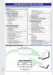
H - Gas connection
I - Power supply cable inlet
B - Water supply connection (0.5- 5 °F)
C - Water drain connection
N - Steam condens. water connection
D - Overflow drain pipe (AIR-BREAK)
( ^) FUNCTIONAL LEVEL
USA
ELECTRIC COMBI - CONVECT OVENS
INSTRUCTIONS FOR INSTALLATION AND USE
Table of contents
Page
- Installation diagram .......................................................... 2
- Appliance identification .................................................... 9
7. Safety devices ............................................................. 18
8. Operation check .......................................................... 18
9. Servicing ....................................................................... 18
10. Troubleshooting ........................................................... 18
11. Layout of main components ...................................... 18
I. MAIN FEATURES ............................................................. 10
1.
2.
3.
4.
Description of appliance ............................................. 10
Table 1: Technical data ................................................. 11
Precautions .................................................................. 12
Safeguarding the environment ................................... 13
4.1 Packaging .............................................................. 13
4.2 Use ......................................................................... 13
4.3 Cleaning ................................................................ 13
4.4 Disposal ................................................................. 13
III. INSTRUCTIONS FOR USE ............................................. 19
1. Opening the oven door ................................................ 19
1.1 6- and 10-grid models ........................................... 19
1.2 20-GRID models .................................................... 19
2. Closing the oven door ................................................. 19
2.1 6- and 10-GRID models ......................................... 19
2.2 20-GRID models .................................................... 19
3. Description of the control panel ................................. 20
3.1 Introduction ............................................................ 20
3.2 Main controls ......................................................... 20
3.3 Main cooking modes ............................................. 20
3.4 Special cooking modes ......................................... 20
3.5 Additional functions ............................................... 21
II. INSTRUCTIONS FOR INSTALLATION ............................ 14
1. Place of Installation ..................................................... 14
1.1 Ventilation ................................................................ 14
1.2 Reference standards ............................................... 14
1.3 Unpackaging ........................................................... 14
1.4 Immediately inspect for shipping damage .............. 14
2. Positioning ..................................................................... 14
3. Combusted gas discharge .......................................... 14
3.1 Foreword .................................................................. 14
3.2 Installation of accessories ................................15
3.3 Warnings regarding the fluimg system .................. 15
4. Electrical connection ................................................... 15
4.1 Installing the power supply cable .......................... 16
5. Water mains connection ............................................. 16
5.1 Water supply characteristics .................................. 16
5.2 Water drain system ................................................ 16
6. Gas connection ............................................................ 17
6.1 Warning .................................................................. 17
6.2 Nominal heat output .............................................. 17
6.3 Checking the supply pressure ............................... 17
USING THE OVEN ................................................................. 22
4. Introduction .................................................................. 22
4.1 Switching the oven on ........................................... 22
4.2 Selecting the controls ............................................ 22
4.3 Manual controls ..................................................... 22
4.4 Automatic controls ................................................. 26
5. Information and error codes ....................................... 29
6. SWITCHING off in the event of a fault ........................ 30
7. Care and maintenance ................................................ 30
7.1 Periodical maintenance of the BOILER ................. 31
7.2 Replacing CONSUMABLE components ............... 32
7.3 Special cleaning instructions ................................. 32
- CONTROL PANEL FIGURES .......................................... 105
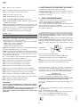
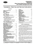
- APPLIANCE IDENTIFICATION
Rating plate
PNC 9PDX 260462 05
2. TABLE 1: TECHNICAL DATA
6GN1/1
5938 036 01
(AOS061E)
260450-260510
260462
260462
260456
26045
260451-260511
260463
260457
2604
°
**
400
3 N~
°
**
230
3~
°
**
200
3~
9
USA
I. MAIN FEATURES
This booklet describes a number of appliance models.
For more detailed information about the model in your possession,
refer to "Technical Data" table 1.
The appliance has the following features:
• Digital temperature controlle.
• Thermostatic probe for measuring the core temperature of products (core temperature probe).
• Automatic flush to drain every two hour to prevent the build-up of
lime-scale in the boiler.
• Periodic draining and automatic washing of the boiler to prevent
the build-up of lime-scale (only available on certain models).
• Boiler lime-scale level indicator (see corresponding paragraph).
• Oven chamber automatic fast steam drain device for gratins.
• Air-break (anti-backup drain) device to prevent backflows from
the drain system from entering the oven (only available on certain
models).
• Halogen lighting in the cooking chamber.
• Double-action door opening safety mechanism designed to
protect the user from scalding steam (only available on certain
models).
• Double-glazed oven door for reduced heat dispersion into the
kitchen and low temperatures on the exterior of the oven.
• Daily oven chamber cleaning cycle (CLEANING SYSTEM).
• Self-diagnostics system indicating oven faults using error codes
(see "Information and error codes ").
5938 036 01
1. DESCRIPTION OF APPLIANCE
10
USA
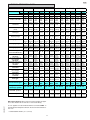
2. TABLE 1: TECHNICAL DATA
6 GN 1/1
GRIDS
PNC *
A^
267550
C^
CONVECTOR °
BOILER **
SUPPLY VOLTAGE
Total W atts
6 GN 2/1
267551
269550
10 GN 1/1
267552
269551
267553
269552
°
267554
269553
°
120V
1ph
60Hz
10amp
120V
1ph
60Hz
10amp
120V
1ph
60Hz
10amp
120V
1ph
60Hz
10amp
120V
120V
120V
120V
120V
120V
120V
120V
1ph
1ph
1ph
1ph
1ph
1ph
1ph
1ph
60Hz
60Hz
60Hz
60Hz
60Hz
60Hz
60Hz
60Hz
10amps 10amps 10amps 10amps 10amps 10amps 20amps 20amps
0,9 kW
0,9 kW
0,5 kW
1 kW
°
**
°
269555
°
**
1 kW
°
267555
269554
°
0,5 kW
°
**
20 GN 2/1
°
**
0,45 kW 0,45 kW
°
**
20 GN 1/1
0,85 kW 0,85 kW
°
**
2 kW
°
2 kW
Maxim um load capacities 66 lbs.
(food)
(30 kg)
66 lbs.
(30 kg)
122 lbs. 122 lbs. 110 lbs. 110 lbs. 220 lbs. 220 lbs. 220 lbs. 220 lbs. 440 lbs. 440 lbs.
(60 kg) (60 kg) (50 kg) (50 kg) (100 kg) (100 kg) (100 kg) (100 kg) (200 kg) (200 kg)
Net w eight
254 lbs.
(115 kg)
254 lbs.
(115 kg)
353 lbs.
(160 kg)
353 lbs.
(160 kg)
320 lbs
(145 kg)
320 lbs
(145 kg)
505 lbs
(229 kg)
505 lbs
(229 kg)
551 lbs.
(250 kg)
551 lbs.
(250 kg)
1058 lbs
(480 kg)
1058 lbs
(480 kg)
Shipping w eight
287 lbs.
(130 kg)
287 lbs.
(130 kg)
386 lbs.
(130 kg)
386 lbs.
(130 kg)
364 lbs.
(165 kg)
364 lbs.
(165 kg)
538 lbs
(244 kg)
538 lbs
(244 kg)
617 lbs.
(280 kg)
617 lbs.
(280 kg)
1080 lbs
(490 kg)
1080 lbs
(490 kg)
38
3/4"inch
(985 mm)
52
3/16"inch
(1325 mm)
37
5/8"inch
(955 mm)
38
3/4"inch
(985 mm)
52
3/16"inch
(1325 mm)
37
5/8"inch
(955 mm)
44
11/16"inch
(1135 mm)
52
3/16"inch
(1325 mm)
44
13/16"inch
(1265 mm)
44
11/16"inch
(1135 mm)
81
1/8"inch
(2060 mm)
51
3/16"inch
(1300 mm)
44
11/16"inch
(1135 mm)
81
1/8"inch
(2060 mm)
51
3/16"inch
(1300 mm)
1" M
1" M
Shipping w idth
Shipping height
Shipping depth
IS O 7/1 ga s
conne ctionDia m e te r
Nom ina l he a t output
NATURAL
Boile r unit nom ina l
he a t output
NATURAL
Convector unit nom inal
heat output
NATURAL
Nom ina l he a t output
P ROP ANE
Boile r unit nom ina l
he a t output
P ROP ANE
Convector unit nom inal
heat output
PROPANE
G as type
Construction type
Diagram of fumes
discharge syste m
44
44
38
38
3/4"inch 11/16"inch 11/16"inch
3/4"inch
(940 mm) (940 mm) (1135 mm) (1135 mm)
42
42
42
42
1/8"inch
1/8"inch
1/8"inch
1/8"inch
(1040 mm) (1040 mm) (1040 mm) (1040 mm)
44
44
37
37
5/8"inch 13/16"inch 13/16"inch
5/8"inch
(980 mm) (980 mm) (1265 mm) (1265 mm)
38
38
44
3/4"inch
11/16"inch 3/4"inch
(1135 mm) (985 mm) (985 mm)
81
81
52
1/8"inch
3/16"inch 1/8"inch
(1325 mm) (2060 mm) (2060 mm)
41
41
44
3/4"inch
13/16"inch 3/4"inch
(1265 mm) (1060 mm) (1060 mm)
1/2" M 1/2" M 1/2" M 1/2" M 1/2" M 1/2" M 1/2" M 1/2" M
68303.6
btu/h
(20 kW)
40982.1
btu/h
(12 kW)
40982.1
btu/h
(12 kW)
61473.2
btu/h
(18 kW)
35859.4
btu/h
(10.5 kW)
35859.4
btu/h
(10.5 kW)
40982.1
btu/h
(12 kW)
_
40982.1
btu/h
(12 kW)
35859.4
btu/h
(10.5 kW)
_
35859.4
btu/h
(10.5 kW)
122946
btu/h
(36 kW)
61473
btu/h
(18 kW)
78549
btu/h
(23 kW)
110993
btu/h
(32.5 kW)
54643
btu/h
(16 kW)
71719
btu/h
(21 kW)
78549 136607.2
btu/h
btu/h
(23 kW) (40 kW)
78549.1
_
btu/h
(23 kW)
78549
78549.1
btu/h
btu/h
(23 kW) (23 kW)
71719 126361.6
btu/h
btu/h
(21 kW) (37 kW)
71718.8
_
btu/h
(21 kW)
71719
71718.8
btu/h
btu/h
(21 kW) (21 kW)
78549.1 177589.3 105870.5
btu/h
btu/h
btu/h
(23 kW) (52 kW) (31 kW)
102455.4
_
btu/h
_
(30 kW)
78549.1 105870.5 105870.5
btu/h
btu/h
btu/h
(23 kW) (31 kW) (31 kW)
71718.8 160513.4 95625.0
btu/h
btu/h
btu/h
(21 kW) (47 kW) (28 kW)
88794.7
_
btu/h
_
(26 kW)
71718.8 95625.0 95625.0
btu/h
btu/h
btu/h
(21 kW) (28 kW) (28 kW)
1" M
232232.2
btu/h
(68 kW)
102455.4
btu/h
(30 kW)
160513.4
btu/h
(47 kW)
208325.9
btu/h
(61 kW)
88794.7
btu/h
(26 kW)
143437.5
btu/h
(42 kW)
1" M
160513.4 379084.9 218571.5
btu/h
btu/h
btu/h
(47 kW) (111 kW) (64 kW)
218571.5
_
btu/h
_
(64 kW)
160513.4 218571.5 218571.5
btu/h
btu/h
btu/h
(47 kW) (64 kW) (64 kW)
143437.5 334687.5 191250.0
btu/h
btu/h
btu/h
(42 kW) (98 kW) (56 kW)
191250.0
_
btu/h
_
(56 kW)
143437.5 191250.0 191250.0
btu/h
btu/h
btu/h
(42 kW) (56 kW) (56 kW)
NATURAL NATURAL NATURAL NATURAL NATURAL NATURAL NATURAL NATURAL NATURAL NATURAL NATURAL NATURAL
PROPANE PROPANE PROPANE PROPANE PROPANE PROPANE PROPANE PROPANE PROPANE PROPANE PROPANE PROPANE
A3
B13
A3
B13
1a-1b-1c
A3
B13
A3
B13
1a-1b-1c
A3
B13
A3
B13
1a-1b-1c
A3
B13
A3
B13
1a-1b-1c
A3
B13
A3
B13
1a-1b-1c
A3
B13
A3
B13
1a-1b-1c
NATURAL pre ssure
7"w c
7"w c
7"w c
7"w c
7"w c
7"w c
7"w c
7"w c
7"w c
7"w c
7"w c
7"w c
(17,4mbar) (17,4mbar) (17,4mbar) (17,4mbar) (17,4mbar) (17,4mbar) (17,4mbar) (17,4mbar) (17,4mbar) (17,4mbar) (17,4mbar) (17,4mbar)
P ROP ANE pre ssure
11"w c
11"w c
11"w c
11"w c
11"w c
11"w c
11"w c
11"w c
11"w c
11"w c
11"w c
11"w c
(27,4mbar) (27,4mbar) (27,4mbar) (27,4mbar) (27,4mbar) (27,4mbar) (27,4mbar) (27,4mbar) (27,4mbar) (27,4mbar) (27,4mbar) (27,4mbar)
Noise emission data: Noise emissions generated by the appliances described in this booklet do not exceed 70 dB (A).
5938 036 01
10 GN 2/1
appliance model is indicated in the box marked PNC on
*theYour
Identification dataplate affixed to the bottom left hand side of
the oven.
^ FUNCTIONAL LEVEL. (C = Convect)
11
USA
3. PRECAUTIONS
Important: The installation instructions contained herein
• The following terms alert you to potentially dangerous conditions
to the operator, service personnel or to the equipment.
• Danger! This term warns of immediate hazards which will result in
severe injury or death.
• Warning! This term refers to a potential hazard or unsafe
practice which could result in injury or death.
• Notice. This term refers to information that needs special
attention or must be fully understood, even though not dangerous.
are for the use of qualified installation and service
personnel only. Installation or service by other than
qualified personnel may result in damage to the appliance
and/or injury to the operator. FAILURE TO COMPLY
WITH INSTALLATION INSTRUCTION OR IMPROPER
INSTALLATION WILL VOID WARRANTY AND
RESPONSIBLITIES OF THE MANUFACTURE.
• Keep the appliance area free and clear from combustibles.
Warning Fire hazard.
For your safety, do not store or use gasoline or other
flammable, vapors and liquids in the vicinity of this or any other
appliance.
Keep area around appliances free and clear of combustibles
Warning!
Failure to properly vent the oven can be hazardous to the
health of the operator; and will result in operational problems,
unsatisfactory baking, and possible damage to the equipment.
Damage sustained as a direct result of improper ventilation will
not be covered by the Manufacturer's warranty.
NOTICE: INTENDED FOR COMMERCIAL USE ONLY. NOT
FOR HOUSEHOLD USE.
CAUTION HOT SURFACES
CAUTION RISK ELECTRIC SHOCK
CAUTION: Do not locate unit adjacent to any high heat or
grease producing piece of equipment, such as a range top,
griddle, fryer, etc., that could allow radiant heat to raise the
exterior temperature of the Oven.
• Our appliances have been studied and optimized to give the
highest performance. This appliance is intended for industrial use
only and is specifically designed to cook food. Any other use will be
considered “improper use” and will void the warranty and
manufacturer liability.
• This appliance is not intended for use by people (including
children) with limited physical, sensory or mental abilities or without
experience and knowledge of it, unless they are supervised or
instructed in its use by a person responsible for their safety.
WARNING: ANY POTENTIAL USER OF THE EQUIPMENT
SHOULD BE TRAINED IN SAFE AND CORRECT OPERATIONG
PROCEDURES.
WARNING: BEFORE SERVICING, DISCONNET THE
ELECTRICAL SERVICE AND PLACE A RED TAG AT THE
DISCONNECT SWITCH TO INDICATED WORK IS BEING DONE
ON THAT CIRCUIT.
NOTICE: Using any parts other than OEM original spare parts
relieves the manufacturer of all warranty and liability.
NOTICE: Manufacturer reserves the right to change specifications
at any time without notice.
Failure to comply with the above requirement may jeopardise
the safety of the appliance and invalidate the guarantee.
WARNING: DO NOT SPRAY THE OUTSIDE OF THE
APPLIANCE WITH WATER OR CLEAN WITH A WATER JET.
CLEANING WITH A WATER JET CAN IMPREGNAT
CHLORIDES INTO THE STAINLESS STEEL, CAUSING THE
ONSET OF CORROSION.
• Carefully read this instruction booklet, as it contains important
advice for safe installation, operation and maintenance.
• Keep this instruction booklet in a safe place for future reference.
WARNING: DO NOT USE PRODUCTS CONTAINING
CHLORINE (BLEACH, HYDROCHLORIC ACID ETC.) EVEN
DILUTED, TO CLEAN STEEL SURFACES.
WARNING: DO NOT USE CORROSIVE SUBSTANCES (E.G.
MURIATIC ACID) TO CLEAN THE FLOOR UNDER THE
APPLIANCE.
• The installation of this unit must conform to local codes or, in the
absence of local codes, to all National Codes governing plumbing,
sanitation, safety and good trade practices.
WARNING: The equipment warranty is not valid unless the
appliance is installed, started and demonstrated under the
supervision of a factory trained installer.
5938 036 01
WARNING: The unit must be installed by Personnel who are
qualified to work with electricity and plumbing. Improper installation
can cause injury to personnel and/or damage to the equipment.
The unit must be installed in accordance with applicable codes.
12
USA
4. SAFEGUARDING THE ENVIRONMENT
4.1 PACKAGING
• All the packaging materials used are environmentally safe and
friendly. They may be stored without fear or danger. They may be
recycled or burned in a special waste incineration plant. Recyclable
plastic components are marked as follows:
polyethylene : external wrapping film, instructions
booklet bag and gas injectors bag
PE
polypropylene: top packaging panels and straps
pp
expanded polystyrene: protective surround elements
PS
4.2 USE
• The appliance has been designed and perfected under laboratory
testing conditions to offer exceptional levels of performance.
However, to minimise energy consumption (electricity, gas and
water), do not leave the appliance in operation for long periods
without food in the oven chamber and avoid conditions that
reduce efficiency (e.g. door open). We also recommend preheating
the appliance immediately prior to use.
4.3 CLEANING
• To minimise the emission of pollutants into the environment,
clean the appliance (externally and, where necessary, internally)
with products that are at least 90% biodegradable.
4.4 DISPOSAL
5938 036 01
• Appliances that have reached the end of their service life should
be suitably disposed of.
• The appliance is made from more than 90% recyclable materials
(stainless steel, iron, aluminium, galvanised sheet steel, etc.).
These materials may therefore be scrapped in accordance with
local waste disposal regulations at a conventional recycling plant.
• Make the appliance unusable by cutting off the power cord. Also
remove any compartment or interior closure device fitted on the
appliance to prevent persons from becoming trapped inside.
13
USA
II. INSTRUCTIONS FOR INSTALLATION
1. PLACE OF INSTALLATION
1.1 VENTILATION
The necessity for a properly designed and installed ventilation
system cannot be over emphasized. The ventilation system will
allow the unit to function properly while removing unwanted vapors
and products of combustion from the operating area.
The appliance must be vented with a properly designed mechanically
driven exhaust hood. The hood should be sized to completely
cover the equipment plus an overhang of a least 6"/15.3cm on all
sides not adjacent to a wall. The capacity of the should be sized
appropriately and provisions for adequate makeup air.
Refer to your local ventilation codes. In the absence of local codes,
refer to the National ventilation code titled, “Standard for the
Installation of Equipment for the Removal of Smoke and Grease
Laden Vapors from Commercial Cooking Equipment”, NFPA-96Latest Edition.
It is recommended that the ventilation system and duct work be
checked at prevailing intervals as specified by the hood manufactured
• The appliance must only be installed in adequately ventilated
premises.
NOTICE: Proper ventilation is the owner's is responsibility. Any
problem due to improper ventilation will not be covered by the
warranty.
1.2 REFERENCE STANDARDS
Note: The electric supply installation must satisfy the requirements
of the appropriate statutory authority, such as the National
Electrical Code (NEC) ANSI/NFPA70, (U.S.A..): the Canadian
Electrical Code, CSA C22.2; or other applicable regulations.
Note: The electric supply connection must meet all national and
local electrical code requirements.
Note: The installation of this unit must conform to local codes or,
in the absence of local codes, to all National Codes governing
plumbing, sanitation, safety and good trade practices, and to the
National Gas Code ANSI Z223.1.
• Local codes regarding installation vary greatle from one area to
another. This equipment is to be installed to comply with the
applicable federal, state or local codes.
The installation instructions contained herein are for the use of
qualified installation and service personnel only. Installation or
service by other than qualified personnel may result in damage to
the appliance and/or injury to the operator.
FAILURE TO COMPLY WITH INSTALLATION INSTRUCTION
OR IMPROPER INSTALLATION WILL VOID WARRANTY AND
RESPONSIBLITIES OF THE MANUFACTURE.
The National Fire Protection Association, Inc states in its NFPA
96 latest edition that local codes are the "authority having
jurisdiction" when it comes to installation requirements for
equipment. Therefore, installations should comply with all local
codes.
1.3 UNPACKAGING
• Remove the appliance from the packaging and take away the
protective film that covers the appliance's external panels carefully to avoid leaving any trace of glue. If necessary remove the
glue using an a non-corrosive solvent, rinsing it off and drying
carefully.
• Dispose of packaging material in compliance with the regulations
in force in the country where the product is to be used.
1.4 IMMEDIATELY INSPECT FOR SHIPPING DAMAGE
The container should be examined for damage before and during
unloading. The freight carrier has assumed responsibility for its
safe transit and delivery. If damaged equipment is received,
either apparent or concealed, a claim must be made with the
delivering carrier. Apparent damage or loss must be noted on the
freight bill at the time of delivery. The freight bill must then be
signed by the carrier representative (Driver). If the bill is not
signed, the carrier may refuse the claim. The supply can supply
the necessary forms. A request for inspection must be made to
the carrier within 15 days if there is concealed damage or loss that
is not apparent until after the equipment is uncrated. The carrier
should arrange an inspection. Be certain to hold all contents plus
all packing material. Under no circumstances should a damaged
appliance be returned to the manufacturer without prior notice
and written authorization.
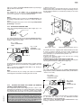
2. POSITIONING
• Refer to the installation diagrams at the beginning of this
booklet for the space requirements and connection dimensions of
the appliance.
• Clearance of approximately 23.62" (50cm) must be left between
the appliance’s left side panel and adjacent structures in order to
provide space for maintenance operations when needed; the
right side panel and the rear panel of the appliance must be at
least 1.97" (5cm) from adjacent structures.
• Place the appliance in the required position and level the oven
with a slight pitch toward the rear to help drain water from
chamber using the appropriate bullet feet.
• The appliance is not suitable for built-in installation.
Warning: The oven must be installed on an even (level) nonflammable flooring and any adjacent walls must be non-flammable.
Recommended minimum clearance are specified in this manaul.
Important:
Make sure steam from the oven’s drain or adjacent
appliances does not enter the aeration vents under the
appliance, designed to cool internal components
located at the bottom of the appliance.
3. COMBUSTED GAS DISCHARGE
3.1
FOREWORD
In relation to the combustion technology utilised, gas fired steam/
convection ovens are classified in accordance with their
"Construction Type". For each of these types of appliances
applicable regulations stipulate a specific type of combusted gas
discharge system.
Consequently, before installing the discharge system:
a) identify the "Construction type" of your model in Table 1
(technical data) or by checking the appliance identification
dataplate;
b) choose the diagram with the type of construction among
those shown as follows (fig. 1a-1b-1c), depending on how you
intend to exhaust the appliance fumes from the place of installation
(e.g. discharge under extraction hood, direct to the outside, or in
a central flue).
14
5938 036 01
Important: The oven outer panels must be removed to
perform the operations described in this chapter. Since the
appliance must be switched on to make certain
adjustments, exercise the utmost care when working in the
vicinity of live electrical parts.
USA
3.2 WARNINGS REGARDING THE FLUING SYSTEM
CONSTRUCTION TYPE
Before installation check, on the basis of the contents of the
reference standard, to ensure that the volume aspirated by the
fumes exhausting system is greater than the volume of combusted
gas produced by the appliance (see point 1.1).
B13
1b
If the solution of combusted gas discharge under an extractor
hood is chosen, observe the distance (shown in the figure)
between the top of the discharge pipe and the lowest point of the
hood filters. This distance is defined on the basis of discharge
pipe diameter "D".
In the case of discharge direction to the outside or into a central
flue (Fig. "1c"), the discharge ducts must NOT present an overall
length in excess of 762"(3 metres), must NOT have any reductions
in diameter, and must be subjected to periodic inspection and,
when necessary, cleaning.
Warning: Since combusted gas (see figure) can reach very
high temperatures, check the heat resistant properties of
extension ducts if fitted and the filters in the extractor hood
to ensure the materials are compatible with the temperature
conditions. In addition, periodically check the condition of
the filters which, if excessively fouled with fat and dirt, will
reduce the efficiency of the suction system and may catch
fire.
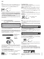
3.3 INSTALLATION OF ACCESSORIES
Accessories can be easily installed by following the figures below
together with the relative key.
The screw holes for fixing accessories "A" and "F" are 0.14"(3.5
mm) in diameter and they must be drilled in-situ on the oven cover
in correspondence with the punch marks.
CONSTRUCTION TYPE
A3
DISCHARGE WITH SHROUD UNDER EXTRACTOR HOOD
CONSTRUCTION TYPE
1a
B13
DIRECT UNDUCTED DISCHARGE UNDER EXTRACTOR HOOD
DISCHARGE TO THE OUTSIDE OR CENTRAL FLUE WITH SHROUD
LEGENDA:
5938 036 01
A:
B:
C:
E:
Cam / draught damper accessory
(to be ordered from manufacturer)
Boiler combusted gas discharge
Oven chamber convector combusted gas discharge
Adapter ring for commercial ducts
(to be ordered from manufacturer)
1c
F:
Conical connections for single outlet (supplied)
(always install)
G:
*:
Fixing screws (supplied);
Commercial extension pipes (not supplied)
SILICONE :
Apply silicone sealant between contact surfaces
15
USA
4. ELECTRICAL CONNECTION
• A fused disconnect switch or main circuit breaker (customer
furnished) MUST be installed in the electric supply line for the
appliance. It is recommended that this switch/circuit breaker
have lockout/tagout capability. Before making any electrical
connections to this appliance, check that the power supply is
adequate for the voltage, amperage, and phase requirements
on the rating plate.
• A safety cutout switch of suitable capacity with a contact
breaking distance of at least 3 mm must be fitted upstream of
the appliance.
The cutout switch must be installed near the appliance in the
permanent electrical system of the premises.
• The appliance must be electrically grounded in accordance
with local codes, or in the absence of local codes, with the
National Electrical Code, ANSI/NFPA 70, or the Canadian
Electrical Code, CSA C22.2, as applicable.
The grounding conductor must therefore be connected to the
terminal marked Gon the connection terminal board. The
appliance must also be connected to an earth grounding
system.
This connection is made using the stop screw marked E
located on the outside of the appliance near the power cable
inlet.
The grounding wire must have a minimum cross-section of
8 AWG (10 mm2).
RATING PLATE
4.1 INSTALLING THE POWER SUPPLY CABLE
To access the power supply cable connection terminal board,
proceed as follows:
Model 6 - 10 - 20 GN
• Remove the left side panel.
• Connect the power supply cable to the terminal board according to the instructions given in the wiring diagram and fasten the
power supply cable by means of strain-relief fitting (not furnished
with the oven).
Failure to comply with safety rules and regulations relieves
the manufacturer of all liability.
The manufacturer requires when stacking units each appliance
have its own branch circuit protection. An oven unit stacked with
an blast chiller unit should have a separate protection for the upper
and lower units.
Before fitting the filters allow the water to flow out for sufficient time
to flush any solid particles from the piping.
5.1 WATER SUPPLY CONNECTIONS
5.1.1 WATER INLET "N".
Attention
The water supply pipe (not supplied) must have a 3/4" dia (20
mm) pipe and must be without elbow fittings.
The steam condensation system must be connected to a cold
quality water supply in keeping with local plumbing codes, with
the following characteristics:
total hardness: total hardness: up to 400ppm (40°fH); in
ovens equipped with CLEANING SYSTEM it is advisable to use
water of hardness no higher than 50ppm (5°fH).
pressure: 22 to 36 psi (150-250 kPa); higher pressure
values result in increased water consumption.
Note:
To check correct water installation, make sure the rotating wash
arm (CLEANING SYSTEM) does not turn below 100 rpm (120
max).
5.1.2 WATER INLET "B".
(water pipe supplied)
The steam production system must be connected to a quality
water supply in keeping with local plumbing codes, with the
following characteristics:
total hardness: 5 - 50ppm (0.5 - 5 °fH) to reduce the buildup of lime-scale inside the boiler.
On request the oven is supplied with an optional water softener
with automatic regeneration which must be installed on inlet line
"B". This device can also be fitted with an optional resin sanitizer
kit.
pressure: 22 to 36 psi (150-250 kPa); higher pressure
values result in increased water consumption.
chlorine ion concentration (Cl -): not more than ~10 ppm
(acceptable value) to avoid damaging the oven's internal steel
parts.
pH: over 7.
The oven can be equipped with an optional special filtration unit
which is installed on inlet line "B". This unit also acts as a water
softener, reducing water hardness to less than 50ppm (5 °fH)
(optimum value).
electrical conductivity: 50 to 2000 µS/cm (68°F)(20°C).
Important: The use of water treatment systems featuring
technology that differs from that of the systems supplied by the
manufacturer is prohibited and will automatically invalidate the
warranty.
The use of dosing systems designed to prevent the buildup of lime-scale in pipes (i.e. polyphosphate dosing
systems) is also prohibited since such systems may impair
the performance of the appliance.
5. WATER MAINS CONNECTION
This equipment is to be installed to comply with the applicable
Federal, State, Local plumbing codes, or the Basic Plumbing
Code of the Building Officials and Code Administrators
International Inc. (BOCA) and Food Service Sanitation Manual
of the Food and Drug Administration (FDA).
When connecting the appliance to the water system with
flexible tubes they must be new and not used.
The appliance is fitted with two separate water inlets ("B" and "N").
The water lines supplying both inlets must be fitted with a
mechanical filter and shut-off valve (keeping with local plumbing
codes).
5.2 WATER DRAIN SYSTEM
- OVEN level A The oven is supplied with an air-break system to prevent any
backflow from the drainage system from reaching the oven’s internal circuits and the cooking chamber. The presence of this
system means that the drain pipe can be connected directly to
the mains drainage system or routed to a floor gulley with grating.
The flexible drainage hose or rigid pipe can be directed to the
side or rear of the appliance if the oven is not positioned against
a wall; this line must not be directed towards the front of the
appliance to prevent interference with roll-in grid racks. The drainage pipe internal diameter must be no smaller than the oven
drain outlet (1 1/4"), no longer than 3 feet (1 metre) and must
16
5938 036 01
(Refer to the installation diagrams at the beginning of this booklet).
USA
resist temperatures of up to at least 212°F (100°C). Avoid restrictions in the case of flexible hose pipes, do not fit elbows on
metal pipes anywhere along the drainage line. Also avoid
horizontal sections in which water might collect (minimum gradient 5%).
6. GAS CONNECTION
6.1 WARNINGS
• Make sure the appliance is set up for the type of gas with
which it will be supplied.
• The gas inlet connector is yellow in colour.
• Before installing consult your local gas utility company to check
the compatibility between the available supply and the
consumption of the appliance.
• Before hooking up the appliance to the gas pipeline remove the
plastic protective plug from the gas connector.
• Fit a rapid gas shut-off cock upline from the appliance in an
easily accessible position.
• On completion of installation, use soapy water to check gas
connections for leaks.
• It is not possible to adjust the combustion air ventilation capacity.
• If the appliance is hooked up to a supply with a different gas type
with respect to the factory setting, after making the necessary
changes check that it is working correctly (see heading 8
"Operation Check").
WARING: BLOCKING THE DRAIN IS HAZARDOUS.
C - Oven drain
C1 - Safety outlet
6.2 NOMINAL HEAT OUTPUT
For data concerning the nominal heat output refer to "Technical
Data" in Table 1.
This parameter is determined by the pressure of the gas supply
and the diameter of the gas valve diaphragm (nozzle).
The appliance nominal heat output must always be checked (by
the authorised installer or by the gas utility company), both in the
case of new installations or following maintenance work.
It is strictly prohibited to make changes to the nominal heat output.
Important:
- Do not obstruct the safety outlet C1.
- Do not connect the safety outlet C1 to the drainage system.
Note:
If water comes out of the AIR-BREAK (safety outlet C1) this means
the drain C is blocked. Any elimination of the obstruction must
be carried out by specialised technical personnel.
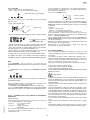
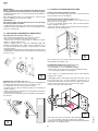
6.3 CHECKING THE SUPPLY PRESSURE (Fig. 2a)
The gas supply pressure must be measured upline from the gas
shut-off cock with the appliance operating, using a pressure
gauge with minimum resolution of 0.1 mbar and proceeding as
outlined below:
1) Remove the left hand side panel to gain access to the gas valve;
2) Loosen sealing screw "C" from the gas valve pressure test point
and connect the pressure gauge hose in its place;
3) Open the gas shut-off cock;
4) Start a mixed cooking cycle (see "Instructions for use") in
such a way that all the burners can be lit;
5) Check that the pressure reading is within the values given in
the following table:
- OVEN level C Connect drain fitting “C” to a drain pipe of the same diameter
which is between 0.5 and 3 metres in length and is resistant to
temperatures of at least 100°C. The drain pipe must be siphoned
(height 80 mm) to an open drain “O” (“Air-Break”) or floor grating
(see Fig. 12b) in order to prevent any back-flow from the sewage
system from reaching the piping inside the oven or oven chamber.
Check the hoses and elbows on metal pipes for kinks or pinching
along the entire drain line and make sure the drain line has a
minimum gradient of 5° to prevent water from collecting inside
the
system.
GAS TYPE
Nom.
Important: The drain system must be installed so that any
vapours from the open drain do not enter the aeration vents
under the appliance.
AIR-BREAK
max 3m
min 0,5m
PRESSURE (MBAR)
NATURAL
PROPANE
7"wc (17,4mbar)
11"wc (27,4mbar)
Min.
Max.
3"wc (8,7mbar) 10"wc (26,1mbar)
8"wc (19,9mbar) 13"wc (32,3,4mbar)
If the values are not within the values shown in the table the
appliance will not function.
In this case inform your gas utility company of the problem;
6) Once you have measured the supply pressure stop the cooking
cycle and close the gas shut-off cock.
7) Disconnect the pressure gauge and carefully refit and tighten
sealing screw "C";
8) Refit the previously removed side panel.
OK
C
min 5°
T max = 100°C
0,08 m
E1
O
AIR-BREAK
E
D
5938 036 01
C
KO
C
O
neywell_sigma
17
2a
USA
7. SAFETY DEVICES
The appliance is fitted with the following safety devices:
- Fuses (see electrical circuit diagram) located behind the control
panel.
To change a fuse unscrew and remove the retainer cap and
replace the blown fuse with an identically rated component; the
fuse rating value is specified on the relative dataplate.
- Oven chamber safety thermostat with manual reset, located
behind the control panel; when this device trips, convection
heating power is disconnected.
Notice: CONTACT YOUR AUTHORIZED SERVICE COMPANY
TO PERFORM MANINTENANCE AND REPAIRS.
- Automatic reset thermal protection inside the cavity fan
motor: this device trips in the event of overheating of the cavity
fan motor; this cut-out protects the appliance by disconnecting the
power supply to the main PC board and an error message is display
EFUN.
"Instructions for use" chapter 5).
- Temperature limiter trip.
- High room air humidity (condensation): ventilate the kitchen.
Burner flame extinguishes (message "burn" appears on display
TM, see "Instructions for use" chapter 5).
Possible causes:
- Power supply polarity (Phase/Neutral) inverted.
- Electrical supply to oven is "Phase/Phase" type. In this case fit the
special "Transformer Kit" available from the manufacturer on request.
- Faulty gas valve.
- Flame detector electrode incorrectly positioned or in open
circuit.
- Burner fan unit damaged (lockout situation).
- Flame control device damaged
- High room air humidity (condensation): ventilate the kitchen.
Oven chamber temperature thermostat control is incorrect.
Possible causes:
- Electronic control panel faulty.
- Oven chamber temperature probe is dirty, faulty, or interrupted,
see error EPt1 (see "Instructions for use" chapter 5).
8. OPERATION CHECK
Oven fails to turn on. Possible causes:
- Electronic control panel is damaged.
- Fuse F2 blown due to damaged control circuit components.
- Switch on the appliance in accordance with the following
section "Instructions for use".
- With the aid of the Instruction Booklet, explain operation,
routine maintenance, and cleaning to the user.
Oven chamber lamps damaged
CAUTION: Before changing oven chamber lamps switch off the
appliance.
Important:
- Exercise due care since certain areas of the oven exterior
become hot during use.
- Do not cover the exhaust outlets on top of the appliance.
11. LAYOUT OF MAIN COMPONENTS
(All work inside the appliance must be carried out exclusively
by a trained installer authorised by the manufacturer)
Removing the control panel provides access to the following
components:
9. SERVICING
Danger: Live voltage is present with panels removed and unit
switch on. Exercise extreme caution when work with live voltage.
All components requiring routine maintenance may be easily
reached by opening the control panel, removing the left side
panel, or removing the rear panel.
-
Danger: Live voltage is present with panels removed and unit
switch on. Exercise extreme caution when work with live voltage.
NOTICE: Using any parts other than OEM original spare parts
relieves the manufacturer of all warranty and liability.
Electronic circuit boards
Oven chamber temperature limit thermostat
Fuses
Door microswitch
Oven chamber lamp transformer
Geared motor for the oven chamber pressure relief butterfly valve.
WARNING: Before servicing unit switch off power at the main
circuit breaker and place a red tag on the breaker to indicate work
is being done on the circuit.
Remove the appliance left hand side panel to gain access to all
the other components.
10. TROUBLESHOOTING
Malfunctions may occur even when the appliance is used correctly.
5938 036 01
Burner fails to light (message "burn" appears on display TM ,
see "Instructions for use" chapter 5).
Possible causes:
- The ignition electrode is incorrectly positioned or the insulation
is damaged. The optimum distance from the outside of the
electrode to the boiler burner is approximately 5 mm(8mm Mod.
20 GN1/1), while the equivalent distance for the convector burner
is approximately 4.5 mm.
- The ignition / flame control device is damaged.
- The ignition electrode high tension lead is broken or shorting
to ground.
- Insufficient gas pressure.
- Faulty gas valve.
- Burner fan unit damaged, insufficient air pressure in combustion
chamber.
- Electronic control panel is damaged.
- Blown fuse, check electrical diagram.
- Oven chamber temperature probe damaged (error EPt1 - see
18
USA
III. INSTRUCTIONS FOR USE
Before switching on the appliance, read this instruction booklet
carefully because it contains important information concerning
correct use of the appliance. If you require further information
about the oven's features and cooking performance, consult your
local dealer.
ANY POTENTIAL USER OF THE EQUIPMENT SHOULD BE
TRAINED IN SAFE AND CORRECT OPERATING PROCEDURES.
• This appliance is intended for industrial use only and is specifically
designed to cook food. Any other use will be considered "improper
use" and will void the warranty and manufacturer liability.
• Do not place pans or utensils on top of the oven. Avoid
obstructing the fumes and steam exhaust outlets.
• Periodically the appliance should undergo a general inspection.
For this purpose we recommend taking out a service contract.
• The core temperature probe is a precision instrument and must
be handled with care. Avoid knocks, do not apply excessive force
when inserting the probe, and do not pull on the lead (take care
particularly when using roll-in racks). The warranty e does not
cover damage to the temperature probe caused by improper
use.
• When using the mixed cooking cycle, do not exceed cooking
temperatures of 392-410°F. Higher temperatures might impair the
performance of the oven chamber seals.
• When placing food in the oven leave a gap of at least 1.5"(40
mm) between each pan to facilitate circulation of hot air.
• If the oven is installed near appliances that produce greasy
fumes (e.g. fryer), make sure to use the air filter (not supplied),
to be placed under the control panel, to protect the internal
electronic components.
• During preheating of the oven 20 GN 1/1 or 2/1, insert the trolley
(without food) to close the bottom opening between the
compartment and door. This prevents steam from coming out
and into the control panel with consequent damage to the
electronic board.
MODELS with SAFETY SYSTEM (by request)
The oven is equipped with a safety system to protect the user
against scalding steam when the door is opened wide. Proceed
as follows:
a)
Turn the oven door handle clockwise as far as it will go.
The door opens slightly and is arrested by the door safety
device.
If there is a cooking program in progress it will be interrupted.
b)
Turn the handle all the way counter-clockwise to open
the oven door fully.
• Do not add salt to foods when inside the oven chamber,
particularly during cooking cycles with humidification.
• Do not cook with flammable liquids such as alcoholic spirits.
1.2 20-GRID MODELS
Attention
Cooking containers can not be inserted at a height greater than
63" (1.6m) from the level where the user operate.
If supporting accessories other than the original ones are to be
used, do not exceed the above specified height since this
could result a spill hazard caused by hot cooking liquids
(sauces, oil, melted fat, etc...) contained in the uppermost pans,
which are not visible during handling operations.
Important! Risk of burns.
Open the door with due care when the appliance is hot.
a)
Turn the handle 90° anticlockwise to open the door fully.
If there is a cooking program in progress it will be interrupted.
1. OPENING THE OVEN DOOR
1.1 6- AND 10-GRID MODELS
Important! Risk of burns.
Open the door with due care when the appliance is hot.
a) Turn the door handle all the way in either direction (indifferently)
to fully open the oven door.
If there is a cooking program in progress it will be interrupted.
2. CLOSING THE OVEN DOOR
2.1 6- AND 10-GRID MODELS
To close the oven door press it until it locks.
5938 036 01
2.2 20-GRID MODELS
a)
Turn the door handle anticlockwise as far as it will go and
press the door closed against the oven.
b)
Keeping the door pressed closed, lock it by turning the
handle to the vertical position.
19
USA
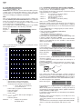
3. DESCRIPTION OF THE CONTROL PANEL
3.1 INTRODUCTION
To aid understanding of the operation of the oven, find the folding
double page showing the control panel for your model among
those included at the back of this handbook and then open it out
and keep it open while reading this section.
The following headings describe all the functions available on the
various models in the range.
Some functions are shared by all models, others are available
on specific models.
Timer to control cooking time.
Digital thermometer/thermostat: to control product core temperature.
3.2 MAIN CONTROLS
3.4 SPECIAL COOKING MODES
Main switch
Utilities
Functions useful for the type of cooking to be executed.
Cooking cycle/program start/stop.
Pause phase: set a time in this mode to delay the start of cooking
programs or to set a pause interval between two cooking cycles
(e.g. for dough proving).
3.3 MAIN COOKING MODES
Air-convection cycle: To roast and gratin with a maximum
temperature of 572°F(300°C)
Mixed cycle: superheated steam. Uses the oven chamber heaters
and steam generation system at the same time to keep food soft
(maximum temperature 482°F)(250°C).
Regeneration cycle: gives ideal humidity conditions for rapid
heating of products to be regenerated (maximum temperature
482°F)(250°C).
The regeneration program is composed of a single phase with the
following characteristics:
- a special cycle with controlled humidity of 20 % (adjustable if
required);
- preset temperature of 248°F (120°C)(can be altered if necessary);
- use of maximum power;
- a preset time of 30 minutes (adjustable if required) and once
started, remains active with door open or closed.
DANGER: CAVITY FAN AND STEAM WILL CONTINUE TO
OPERATE WHEN DOOR IS OPEN. WHEN IN
REGENERATION CYCLE. OPEN DOOR SLOWLY TO
AVOID THE RISK OF BURNS.
Alternatively to the set cooking time it can also accept Cont
cooking time or the core probe.
Steaming cycle: ideal for steam cooking (operating temperature
automatically set at 212°F)(100°C).
You can set low temperature steam for gentle cooking of foods
in vacuum packs and for thawing (temperature from 77°F to
210°F)(25° to 99°C).
HOLD
Cook and hold cycle: for long slow cooking, typically for meat
(large piece of meat for roasting).
It can be used in combination with convection, mixed, steam
and regeneration modes.
Displaying the humidity value: allows you to display the humidity
level of the air-convection, mixed and regeneration cycles.
HACCP: serves to record the cooking program in compliance with
HACCP standards (Hazard Analysis and Critical Control
Points). Depending on the system requested you can record
cooking data on a dedicated printer or directly on a PC.
Digital thermometer/thermostat: to control the temperature in
the oven chamber.
Clean Cycle: automatic or semiautomatic oven cleaning cycle
(see section 7. CARE AND MAINTENANCE).
20
5938 036 01
HACCP
USA
Low speed cycle (fan): for delicate cooking such as for baking
cakes. Can be combined with any other cycle.
Automatic sequence phases: to execute a 2-phase cooking
cycle switching from one phase to the other automatically
(LEVEL C ONLY).
Reduced power cycle (heating): for delicate cooking such as for
baking cakes. Can be combined with any other cycle.
3.5 ADDITIONAL FUNCTIONS
Cooking with ECO-DELTA: for cooking large pieces of food (5kg
and above, e.g. whole turkey, leg of pork, etc.).
In this cooking mode a temperature setting of between 1°C and
120°C is chosen.
In this case, cooking is moderate and long, because the CHAMBER temperature is automatically adjusted according to that
inside the food (CORE PROBE), maintaining a constant difference (ECO-DELTA) between them, from start to end of cooking.
E.g:
COOKING:
START
...... END
ECO-DELTA =
80°... 80...80...
80... 80°C (set)
CORE PROBE =
10°... 11...12...
40... 60°C (set)
CHAMBER
=
90°... 91...92...
120... 140°C
(result)
Set of controls for management of the programs library:
control keys to store, edit or delete cooking programs (LEVEL A
only).
Program selector : to find and select the cooking programs stored
in the memory (LEVEL A only).
Manual water injection into cooking chamber: serves to boost
humidity levels during the cooking cycle.
Air-convection cycle with oven chamber vent open: suitable
for very dry cooking cycles; allows evacuation of humidity when
necessary (maximum temperature 572°F)(300°C).
Boiler manual water draining: press this button to drain the water
from the boiler.
Door open indicator LED.
Important! To prevent the build-up of lime-scale inside the
boiler:
Make sure the water supply corresponds with the required
characteristics - see Installation.
Always empty the boiler at the end of each day.
Limescale LED: when this LED starts flashing the boiler needs to
be descaled. Follow the instructions in section 7.
Boiler status LED:
- LED off: boiler ready;
- LED flashing: boiler filling or no water. Make sure the oven
water supply is working!
Rapid oven cooling: useful for passing from one type of cooking to
another that requires a lower temperature; it allows the fan to run and
automatic water (TS < 356°F)(180°C) injection even when oven
door is open.
5938 036 01
Important! Risk of burns.
Open the door with due care when the appliance is hot.
Cooking parameter adjustment: allows adjustment of cooking
values (humidity, temperature and time).
Before using the oven check that:
- the external safety electric switch is on;
- the water and gas supply valve is open;
- the fumes and steam discharge outlets are not blocked.
21
USA
USING THE OVEN
OPERATING LEVEL
A and C
(C = Convect)
4.2 SELECTING THE CONTROLS
(MANUAL or AUTOMATIC)
The control panel is divided in two parts, one for MANUAL controls
and the other additional section for AUTOMATIC controls .
MANUAL controls
4. INTRODUCTION
AUTOMATIC controls
Cooking of food is carried out by heating it and can be achieved in
a specific MODE, at a specific TEMPERATURE, a specific TIME
and HUMIDITY level. Therefore these parameters must be set in
order to execute a COOKING CYCLE.
On this basis, the oven functions mainly by carrying out the
operations shown in the following headings:
--- SETTING THE COOKING CYCLE --- SELECTING COOKING MODE
- SETTING COOKING TEMPERATURE
- SETTING COOKING TIME
- SETTING AND USING THE PROBE
- SETTING COOKING HUMIDITY
- COOKING CYCLE START
There are also several other headings illustrating support functions
such as:
- MANUAL CYCLE (CONTINUOUS COOKING)
- UTILITIES
- COOKING PHASES IN AUTOMATIC SEQUENCE
Lastly there is a heading describing the storage of cooking cycles
as recipes (e.g. CHICKEN RECIPE) or programs, entitled:
- STORING RECIPES OR PROGRAMS
4.1 SWITCHING THE OVEN ON
To switch the oven on press button I of this switch:
Use one of the two control modes according to your cooking needs
in the level A oven.
The level C oven is equipped exclusively with MANUAL controls.
4.3 MANUAL CONTROLS
SETTING THE COOKING CYCLE
4.3.1 SELECTING COOKING MODE
After SWITCHING THE OVEN ON select one of the following
cooking modes by pressing the relative illuminated button (button
lights up):
steam
conv/steam air-conv.
Set the cooking parameters as indicated in the following paragraphs.
Note:
The temperature and time displays flash for 5 seconds awaiting
setting; if no value is set, the preset value (default value) will remain
stored, which stops flashing.
4.3.2 SETTING THE COOKING TEMPERATURE
Press the following illuminated button (button lights up) to select
cooking temperature:
The following will occur:
- the relative button lights up;
- the control panel switches on and various functions flash;
- the Thermometer/Thermostat TS display shows the oven chamber
temperature;
- the oven chamber lamp switches on;
- boiler in filling
phase
(flashing LED);
- boiler ready
(LED off)
TS
The relative DISPLAY will show the TEMPERATURE in the
CHAMBER (large numbers) and the TEMPERATURE TO BE SET
(small numbers - flash for 5 seconds).
E.g.: 93°F
CHAMBER
TEMPERATURE
E.g.: 392°F
COOKING
TEMPERATURE
Turn the knob clockwise (to increase the value) or counter clockwise
(to decrease the value) to set the desired COOKING
TEMPERATURE in the small DISPLAY.
22
5938 036 01
4.1.1 SWITCHING THE OVEN OFF
To switch the oven off press button O of this switch:
USA
After 5 seconds the COOKING TEMPERATURE stops flashing to
indicate that it has been SET.
1) Switch on the oven.
Remove the product core temperature probe "C" from its seat "D"
and insert it into the product without forcing it and making sure that
the tip (sensitive element) is located in the proximity of the centre
of the product.
Note 1
The temperature of the steam cycle is automatically set at
212°F(100°C). You can, however, set low temperature steam
from 77°F to 210°F(25° to 99°C) by turning the knob.
Note 2
With the COMBI cycle it is possible to do a dough proving cycle
by setting a temperature below 122°F(77 to 121°F), 50°C(25 to
49°C).
When the dough proving cycle is set as a first stage compartment
preheatingis excluded.
4.3.3 SETTING THE COOKING TIME
Press the following illuminated button (button lights up) to set
cooking time:
TM
The relative DISPLAY will show the TOTAL REMAINING TIME of
the cooking cycle (large numbers) and the TIME TO BE SET (small
numbers - flash for 5 seconds).
E.g. : 1 h 30'
TOTAL REMAINING
TIME
LEVEL C
probe with 1 sensor
E.g..: 1 h 30'
CURRENT
REMAINING TIME
LEVEL A
MULTIPOINT probe with 6 sensors
The LEVEL A oven is equipped with a MULTIPOINT probe with
6 sensors located at intervals along the wand, enabling the
correct temperature to be read in the centre of the product even
if the probe tip is not positioned at the product core.
Close the oven door.
2) Select the desired cooking cycle and set the cooking
temperature on thermostat TS.
Important: do not set the cooking time on Timer TM.
3) Set the TEMPERATURE of the CORE PROBE by pressing the
following illuminated button twice (button lights up):
time LED on
Turn the knob clockwise (to increase the value) or counter clockwise
(to decrease the value) to set the desired cooking TIME on the small
DISPLAY.
After 5 seconds the COOKING TIME display stops flashing to
indicate that it has been SET.
PRB
The relative DISPLAY will show the PROBE TEMPERATURE
(large numbers) and the TEMPERATURE TO SET (small numbers
- flash for 5 seconds).
Note:
In this case there is only one cooking cycle or phase so CURRENT
remaining time and TOTAL remaining time will coincide.
E.g.: 135°F
CURRENT PROBE
TEMPERATURE
E.g.: 176°F
REQUIRED
PROBE
TEMPERATURE
5938 036 01
4.3.4
SETTING AND USING THE PROBE (TO MONITOR
PRODUCT CORE TEMPERATURE)
This temperature probe allows high precision control of the
temperature reached at the core of the product being cooked so that
the desired value can be set and the cooking cycle stopped
automatically when the product core reaches the set temperature.
temperature probe
LED on
Im portant: The tem perature probe is a precision
instrum ent and m ust be handled w ith care. Avoid knocks,
do not apply excessive force when inserting the probe, and
do not pull on the lead (take care particularly w hen using
roll-in racks). The guarantee does not cover dam age to the
core tem perature probe caused by im proper use.
23
Turn the knob clockwise (to increase the value) or counter clockwise
(to decrease the value) to set the DESIRED PROBE
TEMPERATURE on the small DISPLAY.
After 5 seconds the DESIRED PROBE TEMPERATURE stops
flashing to indicate that it has been SET.
USA
Note:
Press the button again to switch from the PROBE function to the
TIME function: the relative LED on the DISPLAY will light up.
4) Start the cycle. Press the Cooking Start/Stop button.
5) Stop the cycle. When the required product core temperature
reaches the set temperature the oven stops automatically as
described in heading 4.3.7 STOPPING THE COOKING CYCLE
and elapsed cooking cycle time is shown on the large DISPLAY.
7) Deactivating core probe mode. (Possible only with no cooking
cycle active). Set a cooking time on Timer TM.
Probe cooking mode is also deactivated when the oven is switched off.
At the end of the cycle total cooking cycle TIME is shown on the
large DISPLAY.
The displays will show:
- HU humidity inside the compartment;
- TS automatic compartment preheating (PrEH). To skip preheating press the START button again.
- TM time remaining for end of cooking / PRB core probe temperature.
Note: In TIMED cooking, during preheating the set cooking
time remains unchanged (COUNT-DOWN not activated).
At the end of preheating the message LOAD appears on the
display TS:
- open the oven door and load the food.
- close the door, and the message Strt (START) appears on the
display TS
- press the start cooking luminous button again; it will light up
(FIXED light);
Start COOKING CYCLE
(light FIXED)
(COUNT-DOWN activated)
4.3.5 SETTING COOKING HUMIDITY
(Only in CONVECTION, MIXED and REGENERATION
cooking modes)
Attention
When switching on the oven after several hours in which it has
not been used, wait about 20 seconds (LAMBDA probe
stabilisation time) to ensure accurate reading of the HUMIDITY
value.
Note
To set humidity in AIR-CONVECTION cooking mode press the
relative cycle selection button twice.
After selecting AIR-CONVECTION or MIXED cooking mode the large
DISPLAY (LEVEL A only) will show OVEN CHAMBER HUMIDITY and
the small display (LEVEL A 1%...100% and C 1/10...10/10) will show the
humidity to be SET (flashes for 5 seconds).
E.g.: 60 %
OVEN CHAMBER
HUMIDITY
E.g.: 80 %
COOKING
HUMIDITY
Note:
- No cooking cycle will be available (steam, mixed, air-convection
or regeneration) until the boiler is ready (boiler LED switches off
- see heading 4.1).
During this interval the time count will not start and the Start
cooking button will flash (the same will occur when the oven door
is opened).
Important! Risk of burns.
Open the door with due care when the appliance is hot.
4.3.7 STOPPING THE COOKING CYCLE
When the set time has elapsed the cooking cycle will stop
automatically and the appliance's audible alarm will emit a
continuous beep.
Open the door and remove the product.
Important! Risk of burns.
Open the door with due care when the appliance is hot.
Note:
- The audible alarm can be muted by performing any operation on
the control panel or by opening the door.
To stop the cooking cycle manually press the cycle Start/Stop
button and keep it pressed for two seconds.
If this button is pressed for less than 2 seconds it will produce no
result.
To repeat the last cooking cycle with identical parameters press
the Start/Stop button again.
4.3.6 STARTING THE COOKING CYCLE
- make sure the oven door is closed;
- press the luminous start cooking button, which will light up
(light FLASHING), for COMPARTMENT PREHEATING;
PrEH
Start COMPARTMENT PREHEATING
(light FLASHING)
4.3.8 MANUAL CYCLE (CONTINUOUS COOKING)
Manual cooking cycles can be set by excluding the timer. Follow
the instructions in heading 4.3.2 SETTING THE COOKING TIME
until the display shows the word "cont", i.e. continuous cooking
mode.
In this case the cooking cycle must be stopped manually by
holding down the Start/Stop button for two seconds or by switching
off the oven.
24
5938 036 01
Turn the knob clockwise (to increase the value) or counter clockwise
(to decrease the value) to set the desired COOKING HUMIDITY on
the small DISPLAY.
After 5 seconds the COOKING HUMIDITY value stops flashing to
indicate that it has been SET.
USA
4.3.9 UTILITIES
- Switch on the oven by pressing button I.
- Set a cooking cycle for the following UTILITIES:
2) Set the desired cooking mode, oven chamber temperature,
and cooking time (or, alternatively, core probe temperature) as
described in this handbook.
3) Press the "PHASE" button:
UTILITIES with cycle presetting;
Phase 1 (I) LED
Phase 2 (II) LED
this is not necessary for the other utilities as they are already
specific cycles.
the phase 2 LED switches to RED (active phase) while the phase
1 LED is GREEN (inactive phase); at the same time the cooking
modes button LEDs start flashing again to request a new setting
for phase 2.
5) Select:
- phase 2 cooking mode;
- phase 2 oven chamber temperature;
- time (or core probe temperature) relative to phase 2;
6) The two-phase cooking cycle has now been set. Place the
product to be cooked in the oven and press the START/STOP
button to start the cooking cycle.
The cooking cycle will start from phase 1 (phase 1 LED RED) and
switch automatically to phase 2 (phase 2 LED RED) when the
first phase terminates.
When the oven switches from phase 1 to phase 2 the operator will
be alerted by a brief audible signal.
When phase 2 is terminated the cooking cycle will stop
automatically as already described.
- Press button U (UTILITY):
U (UTILITY)
- The green UTILITY LEDs will light up and one will be flashing.
E.g.:
UTILITY selected
(flashing GREEN LED)
- Turn the knob clockwise or counter clockwise to select the utility
required - the relative LED will flash (flashing GREEN color).
- Press button U until the flashing LED relative to the UTILITY
selected changes colour (flashing ORANGE color).
- Wait a further 5 seconds for the LEDs relative to the selected
utilities to illuminate steadily (steady ORANGE color).
- Finally, start the cycle by pressing the START/STOP button.
4.3.11 Delta Cooking
This is an advanced method of cooking, by which the oven
chamber temperature varies in function of the core temperature
of the food.
The operator is able to select a delta value between 1°C <
120°C, we recommend using between 20°C < 70°C. The chamber
temperature will be adjusted to automatically remain above the
rising core temperature exactly by the set value.
This type of cooking is ideally suited to large joints of meat.
A complete description of the different UTILITIES available is
included in heading 3.4 SPECIAL COOKING MODES (page 20).
Note:
If the UTILITIES are not used for 7 seconds they are
automatically cut out, signalled by the relative button switching
off.
How to use it: Manual cooking mode.
1) Select the cooking mode, Ex. Combi.
2) Set a target core temperature value,
3) Go into advanced utility functions (Bottom row on Control
Panel) and select
- To cancel one of the following preset UTILITIES (ORANGE
steady):
ECO - Delta.
At this point you will see on the oven temperature display 25 °C
which is a Delta value (you can change it by highlighting the
temp area and turning the dial to reach the desired Delta – for
example 50°C.)
Close the oven door and press the start button to activate the
cooking cycle.
The core temperature of the meat may be for example 14 °C
when the cooking cycle is started, the oven temperature will go
to 75°C, (50°C above core temp), and then keep rising as the
core temperature rises, maintaining a difference of 50°C(As the
core temperature of the meat rises by one degree so too does
the oven temperature). The two temperatures will displayed in
the lower line on the display.
If you selected a final core temperature of for ex. 67 °C, the final
oven
chamber temperature will be 117 °C at the end of the cooking
cycle.
This cooking method is much slower than the ‘normal ‘ way of
cooking but the benefits are higher yields and better quality.
press the U button and turn the knob to select it so that it flashes
(ORANGE flashing).
Press the U button again so that the UTILITY changes colour
(GREEN flashing) and is thus cancelled.
- To cancel the other UTILITIES set another cooking cycle.
In case of cycle already started, stop it, keeping the START/
STOP button pressed for 2 seconds before cancelling the UTILITY.
5938 036 01
4.3.10
COOKING WITH TWO PHASES IN AUTOMATIC
SEQUENCE
(LEVEL C ONLY)
Level B ovens allow the execution of cooking cycles composed
of two sequential phases. For example:
- Phase 1:
- air-convection 200°C
- probe 70°C
- Phase 2:
- mixed cycle 220°C
- 40 minutes
The oven switches automatically from phase 1 to phase 2. To set
a two-phase cycle proceed as follows:
1) Switch the oven;
25
USA
4.4 AUTOMATIC CONTROLS
SOLO LIVELLO A
Introduction: the automatic controls make it possible to perform
cooking cycles in special modes and also to store cycles after
manual setting. For information on manual setting procedures
refer first to heading 4.3 MANUAL CONTROLS.
Note:
If the oven is switched off after you have set up a cooking cycle
manually the data you have entered will be lost since, in manual
mode, the controller does not store the cooking cycle.
To store manually set cooking programs for future use proceed
as described in the following headings.
The cooking cycles (or RECIPES) and programs (e.g. CLEAN)
are managed by means of the following commands:
Recipes or
programs ---------Menu* ----------------
DISPLAY
^
<
>
v
* list of commands (items) necessary for executing the various
management functions:
00
06
03
07
09
17
18
10
17
18
11
13
02
14
02
15
16
04
01
05
12
17
18
19
20
21
22
M E N U
A D D
S K
A D D
C L E
C O
R E
C L E
C O
R E
M E M
S E
C
E D
C
S A
R E
S E A
C O
S E A
E X I
C O
R E
P A S
N E
C O
C H A
P
I P
D
A R
N F
T U
A R
N F
T U
O R
L E
O N
I T
O N
V E
T U
R C
N F
R C
T
N F
T U
S W
W
N F
N G
H A
P
E L
P
I R
R N
R
I R
R N
I Z
C T
F I
N
F I
R
R N
H
I R
H
S
H
A
H
M
I
R
O
P
I
E
M
R
N
R
A
R
E
A S E
Y
A S E
R
A
R
E
R E C I P E
N U M B E R
M
M E
M
C I P E
B Y
M
B Y
P H ASE
5) Press button P to confirm this option; the DISPLAY will now
show a flashing number 2 (phase 2) and some of the MANUAL
CONTROL functions will start flashing.
phase 2 flashing
1 2
P : M EN U
6) Set new values, as described in point 2), but this time with
reference to phase 2.
7) To set additional phases repeat steps 4, 5 and 6 up to a
maximum of 7 phases.
8) The multiple phase cooking program has now been set up.
Place the product to be cooked in the oven and press the Start
cycle button.
N U M B E R
D
S S W O R D
M
P A S S W O R D
P A S S W O R D
(^) (v)
= "arrow" buttons (up and down)
(or use the knob) to:
- select recipes, programs or relative names
- select menu items
- select the utilities
- set the values
(<) (>)
=
"arrow" buttons (left and right) to:
- return to menu
- select the phases
=
1
P : A DD
N A M E
P (Program) =
button to:
- open the list of recipes and programs
- open the menu of recipes or programs
- confirm the items selected from the menus
DISPLAY
selected item
selected item
E C I P E
M
E
phase 1 flashing
displays the operations
described above
The cooking cycle will start from phase 1 (value 1 flashes in
alternation with a dot on the relative DISPLAY) and, when phase
1 is terminated, it will advance automatically to phase 2 (value 2
flashes in alternation with a dot on the relative DISPLAY) and so
on until all set phases are completed.
phase 2 in progess
1 2
The transition from one phase to the next is signalled by a short
audible signal.
When the last phase is terminated the cooking cycle will stop
automatically as already described, and the appliance will emit a
double intermittent audible signal.
To repeat the same multiple phase cycle simply press the START/
STOP button again.
While the cooking cycle is in progress you can skip one or more
of the phases as follows:
- press the (>) button one or more times to select the successive
phases.
- press button P once and then press it again at the "SKIP PHASE"
option to confirm the selected phase and cause it to start.
26
5938 036 01
S
S
S
S
S
S
S
S
S
S
S
S
S
S
S
S
S
S
S
S
S
S
S
S
S
S
S
4.4.1 AUTOMATIC SEQUENTIAL MULTIPHASE COOKING
Food can be cooked using different temperatures during the
cooking cycle (i.e. in several different stages).
The oven allows the execution of programs composed of several
sequential phases. For example:
- Phase 1:
- air-convection cycle 392°F (200°C)
- core probe 158°F (70°C)
- Phase 2:
- mixed cycle 428°F(220°C)
- time 40 minutes
- Phase 3:
- air-convection cycle 482°F (250°C)
- time 15 minutes
and so on up to a maximum of 6 phases.
During the cooking cycle the oven advances from one phase to
the next one automatically until the cooking program is completed
and then stops automatically as soon as the last phase has been
terminated.
To set a multiple phase cooking program proceed as follows:
1) Switch on the oven.
2) Set (see heading 4.3 MANUAL CONTROLS):
- cooking mode for phase 1;
- oven chamber temperature for phase 1;
- cooking time (or core probe temperature) for phase 1.
3) Press button P and the DISPLAY will show the flashing value
1 (phase 1) and the description P:MENU.
4) Press button P to open the menu, the option P:ADD PHASE
appears on the DISPLAY (it is also possible to select another
option from the menu).
USA
4) Set the required START time (shown in small numbers on the
TM timer display) and press the START/STOP button.
The cycle will start at the time set in the DELAY START option and
the letter D will flash in alternation with a dot to remind the user that
this function is active.
4.4.2 SETTING THE TIME, DATE AND DELAY START
- TIME and DATE Proceed as follows to set the TIME and DATE:
1) Switch on the oven by pressing button I.
2) Hold down button TM until you hear a beep and the HOUR
digits start flashing.
4.4.3 EDITING THE SET PARAMETERS
With the cooking cycle blocked, started or stored, use the
relative commands to edit the following parameters:
1) cooking mode;
2) cooking temperature TS;
3) cooking time TM;
4) probe temperature PRB (in alternative to cooking time).
TM
3) Turn the knob (while the hour digits are flashing) clockwise or
counter clockwise to set the current hour.
4) Press button TM and set the MINUTES in the same way as for
the hours (step 3).
day
month
year
E.g.: 24-01-2002
CURRENT DATE
Note:
- When you edit the parameters of a STORED cooking program
(during a cooking cycle) an asterisk "*" will appear alongside the
program number.
- Editing the parameters of a STORED cooking program overwrites
the original parameters with the new ones.
E.g.: 9.25
DELAY START
(10 minutes)
Proceed as follows if the oven is performing a cooking cycle
composed of various phases and you wish to edit the parameters
of the next phase to be executed:
a) Press the START/STOP button to stop the current cooking
cycle.
b) Press the (>) button to display the phase you intend to edit, and
enter the new values.
c) Press the START/STOP button to resume the current cooking
cycle.
E.g.: 9.15
CURRENT TIME
hours minutes
timer LED
on
4.4.4 STORING RECIPES OR PROGRAMS
RECIPES or programs (cooking cycles) can be stored with a
sequential number and a descriptive name to assist in retrieval.
E.g.: -01-----(RECIPE n°)
CHICKEN
(RECIPE description)
-02-----POTATOES
Once a RECIPE (composed of one or more cooking phases) has
been set using the MANUAL or AUTOMATIC CONTROLS carry
out these operations:
5) Press button TM again to set the DATE (shown on the
TEMPERATURE DISPLAY) in the same way as the HOURS
(previous step 3).
6) Press button TM to set the MONTH and YEAR repeating the
procedure used to set the date.
- DELAY START- (delayed start of cooking cycle)
Once the TIME and DATE have been set (see previous heading)
carry out these operations:
1) Press button P (program) and select the required recipe or
program:
program
AO
selected
P: MENU
P reHeat
1) Press button P
phase 1 flashing
St e ami ng
selected item
1
P : M EN U
2) Press button P and select P: ADD DELAY.
AO
SELECTED ITEM
P reHeat
P: ADD
St e ami ng
>
DELAY
3) Press button P: a flashing letter D (Delay Start) will be displayed.
LETTER "D"
AO
FLASHING
P: MENU
2) Press button P again to open the menu and select the
MEMORIZE RECIPE option.
D1
phase 1 flashing
selected item
1
P : M E MO R I Z E R E C I P E
5938 036 01
3) Press button P to start saving data, the SELECT NUMBER
option is displayed.
A2
displayed item
27
1
P : S E L E C T NU M B E R
USA
4) Press button P to select the recipe number.
NUMBER OF RECIPE
SELECTED
01
flashing
P : C ON F I RM
5) Select (while flashing) the RECIPE number in which you want
to store the cycle you have just set up and confirm the number by
pressing button P.
N AM E
first recipe
desired recipe
7) Press button P, the dash "_" flashes.
DASH FLASH.
selected item
01
G
P : C O NF I R M
14
G A MM O N
P:MENU
Select the name of the desired recipe from those beginning with
the letter G.
01
P: ED I T
AO
Press the button P to confirm this letter, the first recipe or program
starting with the letter G appears on the display.
with letter G
6) Select the EDIT NAME option
selected item
letter G
selected
15
G OO S E
P:MENU
_
P : C ON F I RM
8) Select the first letter required.
10) Press button P to confirm the RECIPE NAME (e.g.: COOKING
CHICKEN).
NAME RECIPE
selected item
01
C OO K I N G
CHICKEN
P : C ON F I RM
11) Select the SAVE RECIPE option and press button P to save.
NAME OF RECIPE
selected item
01
C OO K I N G
P : SAVE
CHI CKEN
RECIPE
12) Press button P again for a few seconds to exit the programs
(or select the EXIT option and then confirm).
Note: it is not compulsory to save programs in sequence (e.g. 0102-03, etc..): you can assign programs with any number from 0
to 99. Numbers already used for another program are marked
with a dot alongside, while unnoccupied numbers are shown
without a dot. 0
4.4.5 RECIPE OR PROGRAM SEARCH
There are two methods for finding a recipe or program:
- SEARCH BY NUMBER (recipe or program number)
- SEARCH BY NAME (recipe or program name)
Note:
When setting a cooking cycle, press the P button twice and select
the menu item FIND BY NUMBER OR FIND BY NAME, or press
P, holding it down for a few seconds to exit cycle setting and
proceed a follows.
SEARCH BY NUMBER
Press button P and select the desired recipe or program.
SEARCH BY NAME
Press button P to open the list of recipes or programs.
program
selected
AO
C LE A N 1
P : ME N U
Press the button P and select the item SEARCH BY NAME
program
selected
AO
CLEAN 1
P : SE A R C H
BY
N AM E
Press button P to begin the search and select the first letter
of the name of the desired recipe, e.g. G (GOOSE).
4.4.6 USING PRESET PROGRAMS
Undeletable preset programs provide several standard service
functions.
The oven is supplied with the following preset programs:
LOW TEMPERATURE COOKING (EFS-LTC)
Cooking at low temperature is a specific cooking procedure
especially for beef, e.g. prime rib, beef fillet, top round, tenderloin,
but also for other meat items like veal, lamb, venison, turkey,
duck, pork, etc
The meat cuts can be: strip loin, shoulder, leg, saddle, T-bone
steak, rump, fillet, chops, etc.
The EFS-LTC is a preset, fully automatic program to obtain
matured, tender and uniform cooked food.
The program comprises 4 main phases:
PREHEAT, SEARING, MATURE, HOLD.
Set the program as indicated below for the pre-sorted programs.
When the word LOAD appears on the large display, after the
PREHEAT phase
(If necessary change the already set cooking chamber
temperature) PLACE the food in the oven and insert the 6 Point
Multi Sensor, core probe.
(If necessary change the already set probe temperature).
Close the door and start the cycle by pressing the START button
again.
The SEARING (sealing of the food by dry heat) phase starts,
followed by the suddenly Cool Down for subsequent slow
cooking; in the MATURE phase (responsible for tenderising the
meat) the relevant duration flashes on the large display of the
core probe (press any button and the duration disappears).
This is followed by the final HOLD phase to keep the food on a
certain temperature.
The entire LTC cycle (including the HOLD phase) can last for a
max. of 24 hours.
One or more phases can be skipped, going to the next phase
(see SKIP PHASE in par. 4.4.1 AUTOMATIC SEQUENTIAL
MULTIPHASE COOKING); this is useful, for example, when
cooking is started (SEARING phase) with another appliance
(e.g. fry top) and is to be completed in the oven (MATURE and
HOLD phases).
The MATURE phase cannot be skipped; this means that if only
the HOLD phase is to be used just set the relevant UTILITY (see
par. 4.3.10 UTILITIES).
Major advantages:
• Excellent food quality.
• Standardized procedure LTC guarantees repeatable
results
year-in - year-out.
• Typical roast aroma, juiciness from centre to the rim.
28
5938 036 01
9) Press button (>) to enter the next letter as described in point 8
and so on for the rest of the letters to complete the description of
the program (to DELETE a letter select the space).
USA
• Uniform colour and perfected evenness in the degree of
doneness.
• Fast maturing process - time saving and use of fresh cut.
• Significant less cooking shrinkage, 5-8 % (depend on food
quality and selected core temperature).
• Remarkable gain of portions for selling.
• Dramatic energy-saving due to the intelligent EFS - LTC
program.
4.4.7
DELETING A RECIPE OR PROGRAM FROM THE
MEMORY
1) Press button I to switch on the oven.
2) Press button P .
3) Select the recipe or the program to be deleted.
4) Press button P and select the CLEAR RECIPE option.
CLEANING SYSTEM
This system executes an automatic oven chamber cleaning
procedure using suitable detergents according to the level of soil
detected; the program has four different cleaning cycles.
CLEAN 4 X-Strong (super intensive)
For heavy grime resulting from very high fat foods (e.g. roasted
chicken, sausages) also with dry residues (baked-on food).
F00...---> F19... (recipes)
These are the 20 pre-stored recipes of the main international
dishes.
For further information see the relative recipe book.
Proceed as follows to use preset programs:
Note 1:
Before cleaning the compartment with the CLEANING SYSTEM
remove the grease filter (if present).
The CLEANING SYSTEM cycle will commence when the temperature automatically reaches 70°C in the oven chamber.
Before carrying out a CLEANING SYSTEM cycle make sure the
containers (located under the control panel) are supplied with
cleaning products of the required type: refer first to section 7.
CARE AND MAINTENANCE.
P : C LEA R
RE C I P E
RECIPE NAME
01
selected option
P : CO NF I RM
_*******
CO O K I NG P O T A T O E S
factory-set oven password
(8 characters formed of 8 empty spaces)
2) Press P (oven unlocked) and select CHANGE PASSWORD with
the arrow button “v” (down).
3) Press P, the item New PASSWORD appears, enter the password
(alphanumeric 8 characters or less) like entering the name of a
recipe (see par. 4.4.4 STORING RECIPES or PROGRAMMES).
4) Press P, the item CONFIRM PASSWORD requests confirmation
of the password entered by typing it again, then press P. After a short
beep signalling successful operation, or a long beep if failed, the
oven goes to the initial switching on status and is thus unlocked.
To lock it again, just switch it off.
To change a password repeat the previous operations from point 2).
To quit the menu, if the PASSWORD is not known, switch the oven
off and then on again.
Warning:
If the detergent and/or rinse aid containers are empty or the
relative supply lines are empty, before starting the CLEANING
SYSTEM cycle a preparatory cycle must be executed. This
allows the supply pipes to fill with the required liquids and ensures
the subsequent cleaning cycle is performed correctly.
Note 2:
When setting a cooking cycle, press the P button twice and select
the menu item FIND BY NUMBER OR FIND BY NAME, or press
P, holding it down for a few seconds to exit setting and proceed
as follows.
5. INFORMATION AND ERROR CODES
1) Press button P, program A0 flashes
selected
selected option
4.4.8 PASSWORD
The PASSWORD function must be enabled by changing
several parameters; for that purpose request the assistance
of our After-Sales Service.
The PASSWORD allows the following functions to be locked in
order to limit oven use (one or more by request):
- Disables the temporary modification of automatic programmes,
including the special PreHeat, Low Temperature cycles and
Recipes.
- Manual cooking cycles are made unusable.
- Prevents final modification, saving or cancellation of the
automatic programmes.
Once the PASSWORD is enabled, the oven is locked (after
switching on) against the use of the above functions; a password
must be entered to unlock it.
To enter a password:
1) press button P and select the item PASSWORD, press P
again, and the display shows:
CLEAN 3 Strong (intensive)
If the oven chamber is very dirty due to cooking of high fat foods
(e.g. roasted chicken, sausages).
P reHeat
CO O K I NG P O T A T O E S
6) Press button P again and hold it down for a few seconds to exit
the programs.
CLEAN 2 Medium (normal)
If the oven chamber is only moderately soiled and after cooking
fatty foods.
AO
01
5) Press button P to remove the recipe or program from the
memory.
CLEAN 1 Soft (light)
For fresh soil deriving from low fat cooking (e.g. after a STEAM
cooking cycle)
program
RECIPE NAME
St e ami ng
These codes may appear on the time display.
P: MENU
5938 036 01
INFORMATION codes
the message A0 P r e H e a t S t e a m i n g appears on the
DISPLAY.
2) Select the desired program or go to step 3).
3) Press START/STOP to start the A0 PRE-HEAT... cycle.
Codes indicating a value, function, or state.
To exit, edit, skip phase, see the paragraphs of the normal
programs.
cont - Unlimited time setting.
Cln - CLEANING SYSTEM program switched on.
Clnt - Semiautomatic cleaning program switched on.
cool - Oven cooling on.
29
USA
End - End of a cycle or function.
FILL - Boiler filling. (Ensure water supply tap/cock are open).
Hold - Cooking option, HOLD function active.
LOAd - Place the food in the oven.
6. SWITCHING OFF IN THE EVENT OF A FAULT
If the appliance malfunctions, switch off as follows:
• Disconnect the main circuit breaker of the appliance and close
the water and gas valve.
• Contact your authorized service company to perform
maintenance and repairs.
oPEn - Boiler discharge valve opening.
PrEH - (TIME TM / PRB DISPLAY)Boiler preheating.
PrEH -(COMPARTMENT TEMP. DISPLAY TS) Automatic
compartment preheating.
Soap - Detergent. Spray a suitable product on the surfaces to be
cleaned as indicated in point 4) of the semiautomatic chamber
cleaning cycle (see par. 7. CARE AND MAINTENANCE).
StArt - Press the START button to start the program.
7. CARE AND MAINTENANCE
• At the end of each day clean the oven interior with an oven
cleaner, following the product supplier's directions.
• Do not wash the appliance with water jets.
• Do not clean steel surfaces with products containing chlorine
(bleach, hydrochloric acid etc.) even diluted.
• Do not use corrosive substances (e.g. muriatic acid) to clean the
floor under the appliance.
Stby - CLEANING SYSTEM cleaning standby time.
ERROR codes
Codes indicating the need to call technical service
burn - Burner lockout with manual reset by pressing START/
STOP button momentarily. The small DISPLAY shows the
following reference to the type of burner:
- CAUP single convector (6-10 GN) or upper convector (20 GN)
- CADO lower convector (20 GN only)
- BOUP single boiler (6-10-20 GN)
- BODO lower boiler (20 GN2/1 only).
EH2O - Water supply pressure too low for CLEANING SYSTEM
(pressure requirements from 1.5 to 2.5 bar)
EFUN - Fan automatic reset thermal switch device. UP appears
on the small DISPLAY with reference to the single fan (6-10
GN) or upper fan (20 GN) of the chamber and DO in reference
to the lower fan (only 20 GN).
E—- - Non-compliance with a parameter requirement (number
of parameter appears in place of dashes “—”).
EPt1 - Chamber sensor interrupted or short-circuited.
EPt2 - Boiler sensor interrupted or short-circuited.
The appliance has an automatic compartment cleaning programme
called CLEANING SYSTEM; for its use see par. 1.4.3 USING
PRESTORED PROGRAMMES for LEVEL A, whereas for LEVEL
B and C see below.
The CLEANING SYSTEM program uses detergent and rinse aid.
Therefore, fill the DETERGENT container - max. 5 litres (on the
RIGHT with RED cap) and the RINSE AID container - max. 1,2
litres (on the LEFT with BLUE cap) located under the control
panel:
RINSE AID _______________
max. 1,2 litres
__________DETERGENT
max. 5 litres
Use the following cleaning products:
- ECOLAB "Oven Cleaner Power" detergent (not in Gel).
- ECOLAB "Oven Rinse Power" rinse aid (not in Gel).
NB:
Cleaning of the oven chamber is not ensured if a different type of
detergent or rinse aid from that specified above is used.
EPt3 - Probe sensor interrupted or short-circuited.
EPt4 - Bypass sensor interrupted or short-circuited.
ESCH - Malfunction of commands control circuit cooling devices.
Etub - Boiler overtemperature (257°F)(125°C) warning.
Etuc - Chamber overtemperature (608°F)(320°C) warning.
EFLP - Fault in chamber steam discharge motor-operated valve.
ETC - Tripping of chamber temperature limiter.
ETB - Tripping of boiler temperature limiter.
IMPORTANT!
If an error code is displayed during a cooking cycle, the oven
emits a continuous audible warning signal and the cooking
cycle is interrupted.
In this case the oven can be used only in cooking modes that
do not involve the conditions that generated the error.
Notify your Technical Service Center of the alarm code
displayed.
The oven features a UTILITY to perform a automatic or
semiautomatic oven chamber cleaning cycle. Proceed as follows.
In the level A oven, carry out the AUTOMATIC cleaning cycle by
following the instructions in par. 4.4.6 CLEANING SYSTEM.
-----------------
AUTOMATIC (C)
----------------and SEMIAUTOMATIC (A-C) cycle
1) - Remove any large food remnants using a water jet.
Do not use the spray shower or water jets to quickly cool the
compartment and the inside glass of the oven door.
2) - Set the following UTILITY as described in heading 4.3.9
UTILITIES:
3) - Select one of the following wash cycles by turning the knob
on the display TS:
CLNT (semiautomatic) (level A-C)
CLN1...2...3...4 (automatic) (level C) only for the description of
these cycles see CLEANING SYSTEM in par. 4.4.6.
4) - Press the following button to confirm the selection
30
5938 036 01
EPt8 - Electronic controller temperature sensor damaged.
USA
- Disconnect the electrical power supply and close the water and
gas valve;
- Using a cloth soaked in petroleum jelly, vigorously rub the
stainless steel surfaces to apply a light protective film;
- Periodically air the place of storage.
5) - Press the START/STOP button to start the cycle.
————— SEMIAUTOMATIC Cycle only (A-B-C) —————
The cycle will commence when the temperature automatically
reaches 100 °C in the oven chamber.
6) - The 1st cleaning phase (STEAM cycle) ends after 5 minutes,
as signalled by the audible alarm.
7) - Open the oven door and spray the surfaces to be cleaned with
a suitable cleaning product.
8) - Close the oven door. On the TS DISPLAY the 120 second
pass, to allow the degreasing agent to perform its action. At the
end of the degreasing phase the 2nd cleaning phase (STEAM
cycle) lasting 10 minutes starts, after which the alarm sounds
(cycle finished).
7.1 PERIODICAL MAINTENANCE OF THE BOILER
• The build-up of lime-scale inside the boiler is signalled by
illumination of the LED shown below.
9) - Open the oven door and rinse the interior of the chamber.
When this LED illuminates the boiler must be descaled.
The manufacturer declines all liability for failure to clean the
boiler when necessary. Moreover, the repair or replacement
of scale-damaged parts is not covered by the guarantee if the
characteristics of the water supply do not comply with those
stipulated (see corresponding paragraph).
To facilitate the oven chamber cleaning procedure, remove the
guides for roll-in racks located at the bottom of the cooking
chamber and open the air intake wall.
• To open the cooking chamber air intake wall A (Fig. 2) follow
these instructions:
- switch off the oven and disconnect the appliance from the
electrical power supply;
- insert the tip of a screwdriver in opening B and pry inwards
towards the oven (1) to open the side panel by disengaging it from
the pins B1 at the back.
The boiler may be descaled using either:
- pure vinegar (100%);
or
- a chemical descaler (as instructed below).
The oven must be switched on prior to descaling the boiler.
To remove the air intake wall completely follow these instructions:
- unscrew nut C1 with a hex wrench (2).
- lift (3) the air intake wall to disengage it (4) from the lower pin C
of the oven chamber;
- lower (5) the wall to disengage upper pin D and then withdraw
the wall completely (6).
7.1.2 VINEGAR CLEANING METHOD
1) Close the water supply valve.
2) Empty the boiler by pressing the drain button
3) Close the boiler drain after one minute by pressing the above
button.
4) Remove the plastic cap from the boiler filler pipe and pour in 8
litres (6-10gn) or 16 litres (20gn) approx. of pure vinegar.
5) Open the water cock.
6) Run a “steam” cycle for 20 minutes.
7) Switch off the oven and wait 60 minutes.
8) Restart the oven in steam mode for a further 10 minutes.
9) Switch off the oven again and wait 60 minutes.
10) With the water cock open, re-open the drain outlet and drain
off the vinegar (press the above button).
11) Switch off the oven.
12) Insert a rubber hose inside the boiler filler pipe and rinse
thoroughly until the water flowing out of the drain is clear.
13) Refit the filler plug and close the boiler drain (press the above
button).
2
To refit the air intake wall, repeat the steps in reverse order and
retighten nut C1.
5938 036 01
• If present, clean the oven compartment grease filter (not
supplied) at least every three cooking cycles.
• If present, clean the air filter (not supplied) at least once a
month, removing it from underthe control panel.
Failure to clean the filter may affect its performance and impair
cooking.
7.1.3 DESCALER CLEANING METHOD
If you decide to descale the boiler using a chemical product, follow
the directions provided by the product supplier.
For example, when using ECOLAB's “STRIP-A-WAY” descaler,
proceed as follows:
• Follow the instructions given in the previous paragraph and
supply the following product quantities via the boiler filler pipe:
- 2 litres of descaler liquid plus 6 litres of water (6-10gn).
- 4.5 litres of descaler liquid plus 11.5 litres of water (20gn).
• Run a “steam” cycle for 12 minutes.
• Switch off the oven and wait 40 minutes.
• Reopen the boiler drain outlet and proceed as described in the
paragraph above.
• Each day wash the stainless steel surfaces with lukewarm
soapy water and then rinse and dry thoroughly.
• When cleaning stainless steel, never use abrasive tools such as
steel wool, wire brushes or scrapers, since they may leave
ferrous particles which will promote rusting on the steel surfaces.
• If the appliance is not to be used for long periods, proceed as
follows:
31
USA
IMPORTANT - 1
Insert a rubber hose inside the boiler filler pipe and rinse
thoroughly with water to remove all traces of descaling agent.
• Refit the filler plug and close the boiler drain (by pressing the
relative button).
After descaling the boiler, it is good practice to execute a 30minute STEAM cycle with the oven empty.
IMPORTANT - 2
If the water supply cock cannot be easily accessed, to empty
the boiler proceed as follows:
1) Open the boiler discharge valve with the special pushbutton.
2) Wait 2 minutes and switch the oven off; the discharge valve
will close automatically.
7.3 SPECIAL CLEANING INSTRUCTIONS
Cleaning and checking the drain system
Periodically clean the drain pipe and check for obstructions that
may prevent the water from draining.
Cleaning the oven door glazing panels (Fig. 5)
Only clean the panels when the glass is cool and never use
abrasive cloths or detergents.
To access the double glazing cavity, open the internal panel,
which is hinged to the door.
• Open the oven door and press both upper and lower clips F to
release the internal glazing panel.
7.2 REPLACING CONSUMABLE COMPONENTS
Changing the oven chamber lamp (Fig. 3)
If the oven chamber lamp burns out, replace as follows:
• Disconnect the appliance from the power supply.
• Unscrew the four screws fixing flange "A" and remove glass
shield "V" together with seal "G".
• Remove halogen lamp "L" and fit an equivalent lamp with
identical characteristics (12V - 20W - 572°F). Important: do not
touch the new lamp with your fingers, wrap it in paper or a clean
cloth when fitting.
• Refit the glass shield with the seal in the lamp recess then smear
food grade silicone grease on the seal and secure the flange using
the four screws.
5
After cleaning close the internal panel ensuring it is properly
seated against the rubber stops.
CLEANING SYSTEM rotary spray arm (Fig. 6)
Clean the spray arm in the following cases:
- prolonged disuse of the CLEANING SYSTEM
- faulty rotation of the spray arm (nozzles probably blocked)
- use of the appliance with very hard water.
3
Replacing the oven door seal (Fig. 4)
N.B.: The oven door seal is prone to normal wear and aging and
should be replaced whenever it starts to harden or crack.
To change the oven door seal proceed as follows:
• prise the seal out of its seat and remove all traces of old silicone
from the channel.
• apply a bead of silicone sealant in point 1 along the internal frame
of the seal seating channel.
• insert the new seal, pressing it home along the entire length of
the channel.
If the nozzles are completely blocked, remove scale deposits
using the tip of a knife.
• Disengage (without removing) spring clip A from the central
block of the spray arm. For this operation, insert the tip of a
screwdriver in the position shown by the arrow and turn it from the
vertical to the horizontal position as shown in the figure.
• Remove the spray arm from its hub.
4
• Place the spray arm in a bowl full of descaling agent and leave
it to soak overnight, rinsing thoroughly before refitting.
• Refit the spray arm by inserting it over the hub and returning the
spring clip to its original position.
32
5938 036 01
6