1
Multimedia
Projector
Quick Reference Guide
MODEL
LC-X71
LC-X71L
I
Use this book as a reference guide when setting up the
projector. For detailed information about installation,
setup, and operation of the projector, refer to the owner's
manual on the CD-ROM.
READ THE SAFETY INSTRUCTIONS IN THE OWNER'S
MANUAL BEFOREUSINGTHE PROJECTOR.
Printed in Japan
Part No. 6103303871
(1AA6P1 P5214-
KE6BI
@2006 Eiki International. Inc.
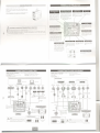
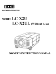
SETTING-UP
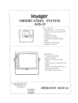
NAME OF EACH PART OF PROJECTOR
FRONTOF CABINET
..,
"", '...
~
h. CAUTION
.Op"",,"c.,m
ill
D? not tu,n on the p,oj..to,
withthe lenscap attached.High:~~
::perature
from light b..m\
y ~8m8ge the lens cap .nd;~~
resu"
on fo,. hezerd.
~
"'1:1:1-1:4::1:1.."
I
~~'II'
/
."h~.
~'~/
.
G
~-
'.
~. .
'
.
i i;~~HH.
'~~~~~iii'i
"'"'''''' .
11 ..
"if':;;;:e"
~.
A
_.:I~J.."'''''~
power system.
If you are not sure of the type of power being supplied,
consult your authorized dealer or service station.
Connect the projector
with all peripheral equipment
before
turning it on.
t:-... . .
I
~
P
!;/
11I1I
i111,
.,
~
CAUTION
For safety,
unplug
the AC power
cord when
is not in use. When the projector is connected
with the AC power
cord, it is in stand-by
~
~
*Option8l:LC-X71l
CORD
voltage.
It is designed
to work with single-phase
power
systems
having a grounded
neutral conductor.
To reduce
risk of electrical
shock, do not plug into any other type. of
,..
.
AC POWER
This projector
uses nominal input voltages of 100-120 V or
200-240
V AC and it automatically
selects
correct
input
- --- .
<
..,-.-
\
.
.
~
~/
PROJECTOR
CONNECTING
consumes
BACK OF CABINET
a little electric
the projector
to an outlet
mode and
power.
.2:t:""h'.''':I~I.
N
&. HOT AIR EXHAUSTED I
NOTE ON POWER CORD
Air blown from the exhaust vent is hot.
When using or Installing the projector.
the following precautions
should be
taken.
AC power cord must meet the requirements of the country where you use the
projector.
Confirm the AC plug type with the chart below and a proper AC power cord must
be used.
If the supplied AC power cord does not match your AC outlet, contact your sates
dealer.
. vent
Do not put a flammable
object
near this
. Keepthe reargrills at least 3.3' (1 m)
I
away from any object, especially from
heat-sensitive objects.
this area, especially
screws and metallic parts. This area will
become hot when the projector is in
use
This
projector
detects
internal
temperature
and automatically controls
operating power of the cooling fans.
AC Outlet
side
Projector
. Donot touch
For the U.S.A.and Canada
I..
..
BOTTOM OF CABINET
_.11:.ll'
Ground
If:
When attaching the Pj-to NetDirector
(optional) to the projector, remove these
parts. Refer to the owner's manual of the
optional PJ-toNetDirector.
I
1~4::a'..~I.'1.~...
side
For Continental Europe
ToPOWER
CORD
..r..
..r..
To the AC Outlet
1120 V AC)
CONNECTORon your
projector.
To the AC Outlet
(200 - 240 V AC)
This projector is equipped with the cooling fans for protecting
from overheating.
Pay attention
to the followings
to ensure
proper ventilation and avoid a possible risk of fire and malfunction.
. Do not cover the vent slots
. Keep this side dear of any objects. Obstructions
may block
coolingair
..'
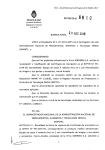
POSITIONING
.. .'
PROJECTOR
NOTE: The figures below are only for the Model LC-X71.
The projection lens is not provided with the Model LC-X71 L
.
.
.
\
This projector is designed to project on a flat projection surface.
Pro,ectorcan
be focused from 4.6' (1.4 m) - 48.2' (14.7 mI.
Refer to the figure below to adjust the screen size
ADJUSTABLE FEET
A ROOM
UGHT
Brightness
in a room
on the picture
influence
has a great
quality.
It is
recommended
to limit ambient lighting
in order to provide the best image.
Projection angle can be adjusted
ADJUSTABLE
FEET.
1
up to 10.5 degrees
Uft the front of the projector
and pull the
. ATCHES in each side of the projector.
2
Release
the
ADJUSTABLE
to a proper
3
LENS SHIFT ADJUSTMENT
Projection lens can be moved up and down with the motor-driven Lens shift function. This function makes it
Co)
to provide
projected
below).
image
HiGhest (10
where
you
want.
The U/D ratio can be adjusted
.
. 0)
10:0
-
To retract the ADJUSTABLE
FEET, lift the front of the
projector and pun and undo the FEET LOCK LATCHES.
Install the projector
properly.
lENS INSTALLATION
install
a projection
lens on
1. Before installation,
check the area where the projector
is
used and prepare a suitable lens. For the specifications
of
a projection
lens, contact
sales
dealer
where
you
purchased the projector.
2. For installation,
optional
refer
to the
installation
Improper
PROJECTOR
installation
IN PROPER
may reduce
POSITION
the lamp life and cause a fire hazard.
1: 1 (see the figure
00 not tilt the projector
more than 10 degrees
Do not put the projector
on either
from
side to side.
10'
~~"u~:
up the projector,
FEET LOCK
FEET LOCK
LATCHES
to lock the
FEET and rotate the ADJUSTABLE
FEET
~.
Before setting
the projector.
the
hight, and tilt.
INSTALLING
easy
with
manual
lens.
t/Note:
o\rV1leninstoJ/ingthe lens. reffiOl'e(he (CNefWP o((he ptOJe<tor.
of the
NO SIDEWAYS
side to project
an image
TERMINALS
MOVING PROJECTOR
Use the Carrying
Handle
when
moving
the projector
This projector
Replace the lens cap and retract the ADJUSTABLE
FEET
to prevent damages to the lens
when moving the projector
and cabinet.
has input
and output
COMPUTER AUDIO INPUT 11
AUDIO MONITOR OUTPUT
JACK
When this protector is not in use for an extended period. put
it into a suitable case (not supplied with this projector!.
This terminal
is switchable
and can be used as Computer
Audio
Input
1 or Audio
Monitor Output (variable).
Set up the terminal as either
Computer
Audio Input 1 or
Audio Monitor Output property
before using this terminal.
terminals
OF PROJECTOR
on its back for connecting
computers
and video
equipment
COMPUTER INPUT
TERMINAL (DIGITAL)
COMPUTER INPUT/MONITOR
OUTPUT TERMINAL (ANALOG)
Connect an audio
output (stereol from a
computer to this jack.
This terminal is switchable
and
can be used as Computer
Input
or Monitor Output.
Set up the
terminal
as either
Computer
Input or Monitor OutPUt properly
before using this terminal
Note: ThIs termin81 outputS from the
5 BNC type compuler input on
INPUT 2 ,acks only.
_'I."1:.IC.).~I.~I:"II']:"'.T.I"IF.I."I:t_
&
CAUTION
IN CARRYING
OR TRANSPORTING
A PROJECTOR
. Do not drop or bump the projector. otherwise damages or malfunctions may result.
. When canying the projector, use a suitable carrying case.
the projector by courier or any other transportservice in an unsuitabletransportcase.
This may cause damage to the projector. To transport the projector by courier or any other transport
service. consult your dealer for the best way.
When controlling
a computer
with the remote control of this
projector. connect USB terminal
of your personal
computer
to
this terminal.
. Donottransport
"12."1::8.:II'.I'h~
This
projector
uses
a micro
processor
to control the unit. and
only
occasionally.
this
micro
processor
may malfunction
and
need to be reset. This can be done
by pressing the RESET bunon with
a pen. which will shut down and
restart
the unit. 00 not use the
RESET function excessively.
:I~[..I.,I:.i...'.'.:..__
Connect component video
output IV.Cb. Cr or Y. Ph, Pr)
from video equipment to
VIDEO/Y, CblPb. and Cr/Pr
jacks or connect computer
output IS BNC Type (Green.
Blue. Red. Horiz. Sync, and
Vert. Sync.)}from computer to
G. B. R. 'rW. and Vjad:s.
.::t
411:::1"1."" ..,:.I::J.':i
:::1'.1 ::1.1...11..'.'.....
Connect external
these terminals.
speakers to
-CONNECTING
..
.
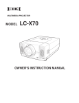
CONNECTING TO VIDEO EQUIPMENT
TO COMPUTERS
..
.
Cables used for connection
(* =:Cables or adapters not supplied with this prOtector.)
VGACable (HDB15 pin)
Control CablefOfPS2 Port e. or ADBPort e
DVI-Digital
Cable (for Single Unk T.M.D.S.!.
USBCable
BNCCable.
Audio
Cables
(Mini
Plug(stereol
)(2).
.
Control
Cable
for
Serial
IBM-rompatible
Port
computer
or Macintosh
computer
Cables
used
for connection
(... Cables not supplied with this prQt8C1orJ
..VideoCable
BNC
Cable
.(RCAI( 1 or RCAx 3) .
..AudioCable
IMiniPkJg(stereoll .
Scart Cablee
..
$-VIDEO Cable _
Audio Cable (RCA I( 2) .
NGAJ$VGAlXGAlSXGAJ$XGA+MlXGAlUXGA)
9
Video
Source
IExafT1)Iel
Video Cassene Recofder
L:
"'p'ootype
Ser1IIpon
\
PS/2pon
ADBpon
RGB Scan
21i*'1Output
Corr4JosAe
Video Output
VIdeoDISCP\ayer
~t
video output equipment
.uc:n..(Nt)~OI"~'oonTV~1
_I
Component Video
Outptrt
(Y, (b'Pb, Cr/Pl1
~Ie
Video Output
COfT'C)OfI8OtVIdeo
OutpUt
(Y, Cb'Pb, CrJPrl
Audio Output
Audio Output
5-VlDEO
Output
..
ControlCable ConvoICabie
fofSer18llPon fofPSnPone
ConwICabie
forADBPon.
,.. .,..
i.=.i -;;,;;:
~
W
~
'- I
.
. -'"
COMPUTER
AUDIO IN 1 or 2
~.
5-VlDEO
-1
I
CJ'I
VIDEO
AUDIOIN
I
S.VIDEO
CONTROL
POftT
COMPUTERIN ANAlOG
NOn:
ThosMt
SMupth8
"""""~
2.
iss...tc:h8b18 r
eott.-
'~-
OUTPut."IOI. "S'"G th,.
-
5:
....
""':"
AUDIO OUT
ggggg-
--=-== _
..~
,;iJC-~-~
~;;)qWl
Extema' Speaker Tennina's
(Front of the projector)
i
~
.
l
'''~'''. -
Tenninals
I
;
I i
of the Projector
.
NO"
ThosMt"""",$tWllc:h8b18
SMupth8I8fmns1........
~"'"ClUlOIMonrtor
o"tput "101. """lIth,.
--
Audio Input
&I
.
NOTE:
tkIpoltgfhepowet"cocJesofbodlrhepto:l!Ctor"awI
u!emol
eqUIpment (TOm the AC outle! before
contIKtIng cables. Turn 0 ptOJKtOf and penpherol
~ipmen[ on before computer is swo!Chedon.
E.xlemal Audro E~I
Audio
Audio
AmplIfier
Speaker!o
(stereo)
IiiI L-II
Exteme' Speaker Terminals
(Front of the projector)
L
REMOTE CONTROL OPERATION
".h'J.:tll...)~1
~
~.,
LeltSide
.
~
beamISemlnedfromthe
LaserligtltW'tfIdoN.
I
J!:
~
to the ~OW position.
I
11
.
.
I.II:8:'
g
:3.aQilE+~
I~1
WTf
Used to mute the sound,
r
~ONt'OFF posotlOf\.
~',~'-
VoIheoUSII'\Qtheremotecontrol,turn
thIS SWitch to .aN.- And turn It 10
'AlL .oFF- when ,t is not in use
.
.1:12...1111.:1
10'.
.
~~~.~e::
~~; ~::r~~iO~~
box
th,- '," acted v.reAn ob;ect
SlIde
the
91'14 tLASERONlOfF
swrtchl
-.oFF" poslt.on. The Laser
Pointer IUOCtionis notopfll8led,
... .1..,:I..:I...I.I~.
=~=~:s=~t~:
~~~~e~o,~~~:~:.~:e~:::~
!t~~;
=u:an~o
.
.
w
N
_
.
011
011 Q8,
011
Q81
011 _
011 Q81
011 _
_
Q8'
01' 011 (10 Q8.
_
011 _
Q81
,
OJ' 001' _
Q81
=
1...!::h.".:'
Used as a PC mouse in
WifelessMouseOperalion.
'
or pertormance
of plocedures
other
_
.
and INDICA TORS
.
The POINT LEFTIRIGHT
.
buttonsare
/.
- ~
--
r
)~.
Input
source (INPUT 1)
:tI'.'''I~.
Used to select
'
.1:
G G
16.4'
Used 10 se~ct an
I
a~ _
I
\Jill"""''''''
Used 10 seIecI me lens Shift
function
used
. as
.1~I:.Ih..:t
-
p.ftIER II'\fI"I
a
also
VOLUME+I-buttons
15m)
C_ _
an input
source
nNPUT 21
""J....
J
I~I:.I
:tI..I.]~.
Used to select an input
source (INPUT 31
.'.'jI'I::I,..t::l.."...=-f"II:18
60'
Whan uSIng as . Wired
Remote Control. connect.
remote control cable loptlOO8ll
to this jack.
Battery instalLation is required
when
using as . Wired
Remote
Control
REMOTE CONTROL
specified
herein
may result
BATTERIES INSTALLATION
3
~~;~~~~~t~~
"""'-.
~-~
_
""
.
~
"
~.
.
~..
in
'
Replace the companment
lid.
T_AAIiz.batt8ri8s
FOfCOl'rectpolanty(+
and -I. be SUfe bal18fY
t8flT'llnalsIfe in contact
~
Press the lid downwdfd
"
end
"'..
""
.~wllhpinsinthe
.
'. :jCOmpartmenl
To Insure safe operation. please observe following precautions:
. Use two (2) AA or LR6 type alkaline batteries.
. Always replace batteries in sets
. Do not use a new battery with an used battery
. Avoid contact with water or liquid
. Do not e)(pose the remote control to moisture, Ofheat.
. Do not drop the remote control.
. If a battery has leaked on the remote control. carefully wipe the case clean and install new
batteries
. Danger of explosion if battery is incorrect)y replaced.
. Dispose of used batteries according to batteries manufacturers instructions and local rules
TOP CONTROLS AND INDICATORS
(TOPCONTROLS)
"""
~~~I~~a~: ~e
\,
These caution Labels are P'Jt on the remote control
This projector has CONTROL BUTTONS
Used 10freeze the pICture
adjust a value 11'IOn-Screen
Menu, They are also
..I.I'h.,.:tll."I~. ~z!.c!!w!!~.I~I:.I
1
than those
\.
the
~sed-';
I~~pera:8
ThIS remote control emits laser beam from the Laser light Window when used as a Laser Pointer. When the lASER button
IS plessed.
the laser hght goes on. When the LASER button is being plessed
for more than one minute or when It is
released.
the light goes off. The lASER POINTER INDICATOR lights RED and the lASER IS emitted with RED light to
indicate the laser beam is being emitted
The laser emitted is the Cass II laser. 00 not loOk into the laser light Window or shine laser beam onto yourself or other
peopte. The three marks shown below are caution labels for the laser beam
Use of controls, adlustments,
hazardous radiation exposure.
I
-.
."
LASER POINTER FUNCTION
CAUTION:
."
;
Used to adtvst zoom.
0
Window) when
eu::~~
. §--.Q:
.
[
A ~
P.TIMER
function
,~
la
Receiver
pressing
any
button.
Ma)(imum
operating
range for the remote control is
about 16.4' !5 mJ and W in front
and rear of the pro;ector.
piCture
projector
- ~. .\. ., ,. .
'-.a_.
.
. Uoed10..''''I eo'.m '"
..
a..'WireJotss Mouse OperatlOf1.
<0.,
Used 10adjust focus
: MW
OperatIOn.
U"d.. . PCmo,,,'0
""""
'0
!!8 _
CS~_'
!~
Used 10
seIec1the MENU
.
keystone
Used 10 turn the .
the
fII&Zf
'
the
I...
Point the remote control toward
I':'
. ! YUTE ~:I'I::I:r"':II~tI
11);.0.)
II'Itoa blaCk wnage
)~.
~
execute
_,'.IIII...,:IItl.JI~:.
D..
U
(~J
t
POinter
10' mOle than one
.
mmUle. release this button
.ndpr8S$,tilQlln
::_-==
,
1~.
.
.
seleCtedltetn. Of expand/
compress
the Image
the DIGITA.L ZOOM+1-
mode
h..I:::II:tll...I...
Used to correct
distortIOn.
to
'
R.ng.
Oper.tlng
""-
1"- ~~fC~.
'"
.
;_INPIITI
'$1 let as the remote beam
emitted
when
presSing sth''>
button for
Of"
DIP SWITCH SETTflG
~
:t:aJo
- ---lASER
,..--
tO,the
Used
~::~toSelectthe.mage
,;.
...1
~
'M Remol8Co<>"~"""", the D'P P".. \hI. b,tloo eod the
SWItchesIOtothe binary c:ompartm'9ntmousepoIOler button to drag
"'1::1'::I".:I'I.I'h"
".
111::8:'
1...
~
,-
"
~~~ALt~~~t~~~
end I8SIl8 lhe 1ITI8Q8.
~~.,:r~~~~ AUTO PC
i
-.
-'::.-,.
t.
~;:p~~~~~~
.m
..a \
.""'1.
.
D.
~:,1iD~,j
I
~
FIUZE
;-mnnnnnnmmm-mnmmnn...
~
~':'I"I;OI~"'-"'on
a::.. 6-'" 1
oroft
o\IJTOPCCIK'II":'
!!!8 !
_
Lights green when dragged
!i
.. . 1
~-".
~
.~
ON-SCREEN
on its top
HOWTO
MENU
OPERATE ON-SCREEN
MENU
You can control and adjust this projector
with On-Screen
Menu. For details. refer to the owner's
manual
__lItoo"':I"".,."::I.'''8
Press the MENU button to display the On-Screen Menu.
"Il.,(I.'ICtI:I.lh.'..::I..
Move the pointer (* see below) or adjust a value of an
item by pressing the POINT buttons on the top control
or on the remote control.
. The Pointer is an
icon
an item. See figures
OPERA TIOW below
_..,.::1.,...:'
1.._
-""'::1.:".:"'.111.'_
.:.!t)'..I::I..'h'!!'I:l:ll:tI~. _1~I:I...:t"."I.'_
close the On-Screen
to e)(ecute the
selected item. It is also
Menu.
used
Used
to
open
or
_::I.III
~t
h'_~,
Uoedto adj"stfoc"s."'--
'
~~f~-;':"~
lhe Leos
QN.(W
~
~
j
w ~h~n :~e
reaches ItS
end of life.
.
Blinks yellow
when
.~-_.
0
_~'.
~
*.;,
.
fj
"..'~i'
<l
efJ
J
U -.n /
~rJI
J
..t... I.~/
e>,_C
.
.
. 0:::::
to select
source.
Menu
for
selecting
OF ON-SCREEN
MENU
-~"'::I'::I"."::I,'......
an
Select an item or set the selected function by pressing
the SELECTbutton.
.::0
'.
. ..
1.I.f'fS""'O-
d..' " OIllrl'lTOlC
...
the
. .,
""
:i.II~
~
"
,"
.
~
- ~
~~
,(.I..h...ZW.8!!l.:I...I'I~
U.ed 10ope'ale the Auto
PC Adjustment function
. .. ..:
_"'JNr!::8~I"."
Used
to
select
Becomes dim when the
projector IS turned on.
becomes
FLOW OF ON-SCREEN
OPERATION
MENUBAR~_
1
Press
Menu
the MENU button to display the On-Screen
(a MENU BARL A red frame is a POINTER.
2
Move
the
L ~M":'-J
LJ
~._
..
POINTER
(red frame)
to a MENU
ICON
that you want to select by pressing the POINT
RIGHTILEFTbuttons
IC
=.:::-"
3
""~,,,,.,.'''"''''''''the
Pfo;ectOf is ready to be
turned on. And it blinks
green
in the Power
management mode.
4
the
SELECT
Adjust the ITEM DATA by pressing the POINT
RIGHTILEFT
buttons.
_~
.
POINTERIredtramel
_
.__J
,
(~I~~I
Pressthe POINTUP,{)OVIJN
.~ITEM
Press the POINT UP/DOWN
buttons and move the
POINTER (red frame or red arrow) to an ITEM that
you want to adjust, and then press
button to show the ITEM DATA.
~~,
.:.. .~. J 4 "\
...
buttons to move the POINTER
bright
.'."".I.'II.'[t8I:1,'..:8h'I.II.,..'I'I.. lights green when
Used to select an item or adjust a Blinks red when the internal
value In On-Screen Menu. They are temperature of the projector
also used to pan the image in the is too high.
DIGITAL ZOOM +/- mode.
The POINT lEFT/RIGHT buttons are
also used as VOLUME +/- bunons
MENU
I~~
_"'1"'1=--1""1["'.'''1'_
it
L-
1
Uoedto conect
keystonedistortion.
And
I
the
LL---".n "'"".........
~r:t
.
prOf8Cl.IOI"I
lamp
/
0-1
.
..
~.'
i'.
Tu~~" t~ ~e;,o
Used
input
to expand/compress
DIGITAL
/
~\
Usedto adjustzoom.
turn the Pfo,ectOf
On-Screen
in HFlOW
the image in the
ZOOM mode.
"
___"'''lh',':III.''h'_
Used to
on or off
Used
in the
'
.'
l~tE=:EJf:
I~'
. L~
. ~::]!I,
I:~.I
I
'\
~:T~INTLEFTJRiGHT
buttons to aellust a v8Iue Of seta
t,O<1~
]
TURNING
ON / OFF PROJECTOR
TURNING ONTHE PROJECTOR
1
2
3
4
TURNING OFFTHE PROJECTOR
Complete peripheral connections. (with a computer,
VCR, etc.) before turning on the proJector.
1
Connect the projector's AC power cord into an AC
outlet. The LAMP indicator lights RED, and the READY
indicator lights GREEN.
2
Press the POWER ON-OFF bunoo o.n the top ~ontrol or
on the remote control. The LAMP mdicator dims. and
the cooling fans start to operate. The preparation
display appears on the screen and the countdown
starts.
After the countdown. the input source that was
selected the last time and the Lamp control status icon
appear on the screen.
If the prOjector is locked with a PIN code, a PIN code Input
DialogBox appears. Enter a PIN code as instructed below
The preparation
Selected
display
disappears
after
Press the POWER ON-OFF button on the top control or
on the remote
control, and "Power off?" appears on
the screen.
Press
30 seconds
F=
""
3
I
I tGI(/<C
Q «
00
Repeat this step to complete entering a four.(jigit number.
When the four-digit number is fixed, the pointer automatically
moves to "Set. ~ Press the SElECTbutton so that you can start to
operate the prOJector.
If you entered a wrong PIN code. UPIN code" and the number
(***.)
turn red and disappear. Enter a PIN code all over again.
What
is PIN code?
PIN (Personal Identification Number) code is a security code that
allows the person who knows it to operate the projector. Setting a
PIN code prevents unauthorized use of the projector.
A PIN code consists of a four digit number. Refer to PIN code lock
function in SETTING Menu in the owner's manual for locking the
operation of the projector with your PIN code.
CAUTION
ON HANDLING PIN CODe
If you forget your PIN code. the projector can no
longer be started. Take special care in setting a new
PIN code; write down the number in a column on
page 60 of the owner's manual and keep it at hand
Should the PIN code be missing or forgotten, consult
your dealer or service center
~'" ...,.
..
co...
button
again
t?
turn
off
the
Indicator lights GREEN agaIn and you can turn projector
on. After cooling
down completely,
unplug
the AC
power cord.
Lampcontrotstatus
c:::=::::J$
TO MAINTAIN THE LIFE OF LAMP, ONCE YOU TURN
THE PROJECTOR
ON, WAIT AT LEAST FIVE
MINUTES BEFORE TURNING IT OFF
DO NOT UNPLUG THE AC POWER CORD WHILE
COOLING FANS ARE RUNNING OR BEFORE THE
READY
INDICATOR
LIGHTS
GREEN
AGAIN.
OTHERWISE IT WILL RESULT IN SHORTENING THE
LAMP LIFE.
.
.
...L.Pointer
I
.. m. 0!CJ'" '"I
~
ON-OFF
When the projector has .cooled down, the READY
I
To Enter a PIN code
by pressing the POINT LEFTIRIGHT button and fix
the number with the SELECT button. The number changes to "*. ~
If you fixed a wrong number, move the pointer to "Set~ or ~Clear~
once by pressing the POINT DOWN button, then return to ~PIN
code. ~ Enter the correct number.
POWER
Input Source and Lamp control
PIN code Input Di.log Box
Select a number
the
projector. The lAMP Indicator lights brrght and the
READY Indicator turns off. After the projector is turned
off, the cooling tans operate (for 90 seconds). During
this "cooling down" period, the projector cannot be
turned on
After the OK icon
disappears, you can
operate the projector
"'Note:
.
The projector
connor be rumed on during the cooling period with the
READY indi<awwmed off. You can wrn it on agarn after the READY
indicator becomesGREENagain.
When the On srort funcrion is "On." rhis prOjector is turned on
.
.
.
.
O!Jromofically
Continuous
and
by connecting
use may resulr
the AC power
in shortening
resr ir for abour an hour.n
The running
speed
of cooling
every
24
con:J to an AC O<Jr1et
the lamp
life. Turn off the projectof-
hours.
fans is chonged
according
0 the
remperarure
inside the PR1j«ror.
If rhe WARNING TEMP indicator blinks RED. see 'WARNING TEMP
INDICATORHin the owners monoaf.