1
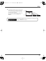
To resize thickness, move all items on the front cover
and center registration marks to left or right.
Information
EDIROL (Europe) Ltd.
Studio 3.4 114 Power Road
London W4 5PY
U. K.
TEL: +44 (0)20 8747 5949
FAX:+44 (0)20 8747 5948
http://www.edirol.com/europe
Deutschland
TEL: 0700 33 47 65 20
France
TEL: 0810 000 371
Italia
TEL: 02 93778329
U. S. A. / CANADA
EDIROL Corporation
North America
425 Sequoia Drive, Suite 114
Bellingham, WA 98226
U. S. A.
TEL: (360) 594-4273
FAX: (360) 594-4271
http://www.edirol.com/
HONG KONG
BARBADOS
PERU
IRELAND
CYPRUS
Parsons Music Ltd.
8th Floor, Railway Plaza, 39
Chatham Road South, T.S.T,
Kowloon, HONG KONG
TEL: 2333 1863
A&B Music Supplies LTD
12 Webster Industrial Park
Wildey, St.Michael, Barbados
TEL: (246)430-1100
Audionet
Distribuciones Musicales SAC
Juan Fanning 530
Miraflores
Lima - Peru
TEL: (511) 4461388
Roland Ireland
G2 Calmount Park, Calmount
Avenue, Dublin 12
Republic of IRELAND
TEL: (01) 4294444
Radex Sound Equipment Ltd.
17, Diagorou Street, Nicosia,
CYPRUS
TEL: (022) 66-9426
INDIA
Rivera Digitec (India) Pvt. Ltd.
409, Nirman Kendra
Mahalaxmi Flats Compound
Off. Dr. Edwin Moses Road,
Mumbai-400011, INDIA
TEL: (022) 2493 9051
INDONESIA
PT Citra IntiRama
J1. Cideng Timur No. 15J-150
Jakarta Pusat
INDONESIA
TEL: (021) 6324170
KOREA
Cosmos Corporation
1461-9, Seocho-Dong,
Seocho Ku, Seoul, KOREA
TEL: (02) 3486-8855
MALAYSIA/
SINGAPORE
Roland Asia Pacific Sdn. Bhd.
45-1, Block C2, Jalan PJU 1/39,
Dataran Prima, 47301 Petaling
Jaya, Selangor, MALAYSIA
TEL: (03) 7805-3263
AFRICA
EGYPT
Al Fanny Trading Office
9, EBN Hagar A1 Askalany
Street,
ARD E1 Golf, Heliopolis,
Cairo 11341, EGYPT
TEL: 20-2-417-1828
REUNION
Maison FO - YAM Marcel
25 Rue Jules Hermann,
Chaudron - BP79 97 491
Ste Clotilde Cedex,
REUNION ISLAND
TEL: (0262) 218-429
SOUTH AFRICA
Paul Bothner(PTY)Ltd.
17 Werdmuller Centre,
Main Road, Claremont 7708
SOUTH AFRICA
TEL: (021) 674 4030
PHILIPPINES
G.A. Yupangco & Co. Inc.
339 Gil J. Puyat Avenue
Makati, Metro Manila 1200,
PHILIPPINES
TEL: (02) 899 9801
TAIWAN
ROLAND TAIWAN
ENTERPRISE CO., LTD.
Room 5, 9fl. No. 112 Chung
Shan N.Road Sec.2, Taipei,
TAIWAN, R.O.C.
TEL: (02) 2561 3339
THAILAND
Theera Music Co. , Ltd.
330 Verng NakornKasem, Soi
2, Bangkok 10100, THAILAND
TEL: (02) 2248821
VIETNAM
Saigon Music
Suite DP-8
40 Ba Huyen Thanh Quan
Street
Hochiminh City, VIETNAM
TEL: (08) 930-1969
ASIA
CHINA
Roland Shanghai Electronics
Co.,Ltd.
5F. No.1500 Pingliang Road
Shanghai 200090, CHINA
TEL: (021) 5580-0800
Roland Shanghai Electronics
Co.,Ltd.
(BEIJING OFFICE)
10F. No.18 3 Section Anhuaxili
Chaoyang District Beijing
100011 CHINA
TEL: (010) 6426-5050
Roland Shanghai Electronics
Co.,Ltd.
(GUANGZHOU OFFICE)
2/F., No.30 Si You Nan Er Jie
Yi Xiang, Wu Yang Xin Cheng,
Guangzhou 510600, CHINA
TEL: (020) 8736-0428
AUSTRALIA/
NEW ZEALAND
AUSTRALIA/
NEW ZEALAND
Roland Corporation
Australia Pty.,Ltd.
38 Campbell Avenue
Dee Why West. NSW 2099
AUSTRALIA
For Australia
Tel: (02) 9982 8266
For New Zealand
Tel: (09) 3098 715
CENTRAL/LATIN
AMERICA
ARGENTINA
Instrumentos Musicales S.A.
Av.Santa Fe 2055
(1123) Buenos Aires
ARGENTINA
TEL: (011) 4508-2700
BRAZIL
Roland Brasil Ltda.
Rua San Jose, 780 Sala B
Parque Industrial San Jose
Cotia - Sao Paulo - SP, BRAZIL
TEL: (011) 4615 5666
CHILE
Comercial Fancy II S.A.
Rut.: 96.919.420-1
Nataniel Cox #739, 4th Floor
Santiago - Centro, CHILE
TEL: (02) 688-9540
COLOMBIA
Centro Musical Ltda.
Cra 43 B No 25 A 41 Bododega 9
Medellin, Colombia
TEL: (574)3812529
CURACAO
Zeelandia Music Center Inc.
Orionweg 30
Curacao, Netherland Antilles
TEL:(305)5926866
TRINIDAD
AMR Ltd
Ground Floor
Maritime Plaza
Barataria Trinidad W.I.
TEL: (868)638 6385
URUGUAY
Todo Musica S.A.
Francisco Acuna de Figueroa 1771
C.P.: 11.800
Montevideo, URUGUAY
TEL: (02) 924-2335
VENEZUELA
Instrumentos Musicales
Allegro,C.A.
Av.las industrias edf.Guitar
import
#7 zona Industrial de Turumo
Caracas, Venezuela
TEL: (212) 244-1122
DOMINICAN REPUBLIC
Instrumentos Fernando Giraldez
Calle Proyecto Central No.3
Ens.La Esperilla
Santo Domingo,
Dominican Republic
TEL:(809) 683 0305
EUROPE
ITALY
Roland Italy S. p. A.
Viale delle Industrie 8,
20020 Arese, Milano, ITALY
TEL: (02) 937-78300
IRAN
MOCO INC.
No.41 Nike St., Dr.Shariyati Ave.,
Roberoye Cerahe Mirdamad
Tehran, IRAN
TEL: (021) 285-4169
NORWAY
ISRAEL
Roland Scandinavia Avd.
Kontor Norge
Lilleakerveien 2 Postboks 95
Lilleaker N-0216 Oslo
NORWAY
TEL: 2273 0074
Halilit P. Greenspoon & Sons
Ltd.
8 Retzif Ha’aliya Hashnya St.
Tel-Aviv-Yafo ISRAEL
TEL: (03) 6823666
POLAND
AMMAN Trading Agency
245 Prince Mohammad St.,
Amman 1118, JORDAN
TEL: (06) 464-1200
MX MUSIC SP.Z.O.O.
UL. Gibraltarska 4.
PL-03664 Warszawa POLAND
TEL: (022) 679 44 19
PORTUGAL
Roland Iberia, S.L.
Portugal Office
Cais das Pedras, 8/9-1 Dto
4050-465, Porto, PORTUGAL
TEL: 22 608 00 60
ROMANIA
JORDAN
KUWAIT
EASA HUSAIN AL-YOUSIFI
& SONS CO.
Abdullah Salem Street,
Safat, KUWAIT
TEL: 243-6399
LEBANON
FBS LINES
Piata Libertatii 1,
535500 Gheorgheni,
ROMANIA
TEL: (266) 364 609
Chahine S.A.L.
Gerge Zeidan St., Chahine
Bldg., Achrafieh, P.O.Box: 165857
Beirut, LEBANON
TEL: (01) 20-1441
RUSSIA
OMAN
BELGIUM/FRANCE/
HOLLAND/
LUXEMBOURG
MuTek
3-Bogatyrskaya Str. 1.k.l
107 564 Moscow, RUSSIA
TEL: (095) 169 5043
TALENTZ CENTRE L.L.C.
P.O. BOX 37, MUSCAT,
POSTAL CODE 113
TEL: 931-3705
SPAIN
QATAR
Roland Central Europe N.V.
Houtstraat 3, B-2260, Oevel
(Westerlo) BELGIUM
TEL: (014) 575811
Roland Iberia, S.L.
Paseo García Faria, 33-35
08005 Barcelona SPAIN
TEL: 93 493 91 00
Badie Studio & Stores
P.O. Box 62,
Doha, QATAR
TEL: 423554
HONDURAS
CZECH REP.
SWEDEN
SAUDI ARABIA
Almacen Pajaro Azul S.A. de C.V.
BO.Paz Barahona
3 Ave.11 Calle S.O
San Pedro Sula, Honduras
TEL: (504) 553-2029
K-AUDIO
Kardasovska 626.
CZ-198 00 Praha 9,
CZECH REP.
TEL: (2) 666 10529
Roland Scandinavia A/S
SWEDISH SALES OFFICE
Danvik Center 28, 2 tr.
S-131 30 Nacka SWEDEN
TEL: (0)8 702 00 20
aDawliah Universal
Electronics APL
Corniche Road, Aldossary
Bldg., 1st Floor, Alkhobar,
SAUDI ARABIA
MARTINIQUE
DENMARK
SWITZERLAND
Musique & Son
Z.I.Les Mangle
97232 Le Lamantin
Martinique F.W.I.
TEL: 596 596 426860
Roland Scandinavia A/S
Nordhavnsvej 7, Postbox 880,
DK-2100 Copenhagen
DENMARK
TEL: 3916 6200
Roland (Switzerland) AG
Landstrasse 5, Postfach,
CH-4452 Itingen,
SWITZERLAND
TEL: (061) 927-8383
P.O.Box 2154, Alkhobar 31952
SAUDI ARABIA
TEL: (03) 898 2081
FINLAND
UKRAINE
Roland Scandinavia As, Filial
Finland
Elannontie 5
FIN-01510 Vantaa, FINLAND
TEL: (0)9 68 24 020
TIC-TAC
Mira Str. 19/108
P.O. Box 180
295400 Munkachevo,
UKRAINE
TEL: (03131) 414-40
ECUADOR
Mas Musika
Rumichaca 822 y Zaruma
Guayaquil - Ecuador
TEL:(593-4)2302364
GUATEMALA
Casa Instrumental
Calzada Roosevelt 34-01,zona 11
Ciudad de Guatemala
Guatemala
TEL:(502) 599-2888
Gigamusic SARL
10 Rte De La Folie
97200 Fort De France
Martinique F.W.I.
TEL: 596 596 715222
MEXICO
Casa Veerkamp, s.a. de c.v.
Av. Toluca No. 323, Col. Olivar
de los Padres 01780 Mexico
D.F. MEXICO
TEL: (55) 5668-6699
NICARAGUA
Bansbach Instrumentos
Musicales Nicaragua
Altamira D'Este Calle Principal
de la Farmacia 5ta.Avenida
1 Cuadra al Lago.#503
Managua, Nicaragua
TEL: (505)277-2557
AUSTRIA
Roland Elektronische
Musikinstrumente HmbH.
Austrian Office
Eduard-Bodem-Gasse 8,
A-6020 Innsbruck, AUSTRIA
TEL: (0512) 26 44 260
GERMANY
Roland Elektronische
Musikinstrumente HmbH.
Oststrasse 96, 22844
Norderstedt, GERMANY
TEL: (040) 52 60090
GREECE
STOLLAS S.A.
Music Sound Light
155, New National Road
Patras 26442, GREECE
TEL: 2610 435400
HUNGARY
Roland East Europe Ltd.
Warehouse Area ‘DEPO’ Pf.83
H-2046 Torokbalint,
HUNGARY
Owner’s Manual
EUROPE
When you need repair service, call your nearest EDIROL/Roland Service Center or authorized
EDIROL/Roland distributor in your country as shown below.
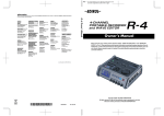
Owner’s Manual
201a
Before using this unit, carefully read the sections entitled: “USING THE UNIT SAFELY” and “IMPORTANT
NOTES” (p. 3– p. 6). These sections provide important information concerning the proper operation of the unit.
Additionally, in order to feel assured that you have gained a good grasp of every feature provided by your new
unit, Owner’s Manual should be read in its entirety. The manual should be saved and kept on hand as a
convenient reference.
SYRIA
Technical Light & Sound
Center
Rawda, Abdul Qader Jazairi St.
Bldg. No. 21, P.O.BOX 13520,
Damascus, SYRIA
TEL: (011) 223-5384
TURKEY
UNITED KINGDOM
Roland (U.K.) Ltd.
Atlantic Close, Swansea
Enterprise Park, SWANSEA
SA7 9FJ,
UNITED KINGDOM
TEL: (01792) 702701
MIDDLE EAST
Ant Muzik aletleri ithalat ve
ihracat Ltd Sti
Siraselviler Caddesi
Siraselviler Pasaji No:74/20
Taksim - Istanbul, TURKEY
TEL: (0212) 2449624
U.A.E.
Zak Electronics & Musical
Instruments Co. L.L.C.
Zabeel Road, Al Sherooq Bldg.,
No. 14, Grand Floor, Dubai,
U.A.E.
TEL: (04) 3360715
BAHRAIN
Moon Stores
No.16, Bab Al Bahrain Avenue,
P.O.Box 247, Manama 304,
State of BAHRAIN
TEL: 17 211 005
TEL: (23) 511011
As of January 15, 2005 (EDIROL-1)
Copyright © 2005 ROLAND CORPORATION
All rights reserved. No part of this publication may be reproduced in any form
without the written permission of ROLAND CORPORATION.
03783701
’05-2-1N
To resize thickness, move all items on the front cover
and center registration marks to left or right.
For the U.K.
For EU Countries
IMPORTANT: THE WIRES IN THIS MAINS LEAD ARE COLOURED IN ACCORDANCE WITH THE FOLLOWING CODE.
CAUTION
BLUE:
NEUTRAL
BROWN: LIVE
Danger of explosion if battery is
incorrectly replaced.
Replace only with the same or
equivalent type recommended by the
manufacturer.
Discard used batteries according to the
manufacturer’s instructions.
Apparatus containing
Lithium batteries
ADVARSEL!
As the colours of the wires in the mains lead of this apparatus may not correspond with the coloured markings identifying
the terminals in your plug, proceed as follows:
The wire which is coloured BLUE must be connected to the terminal which is marked with the letter N or coloured BLACK.
The wire which is coloured BROWN must be connected to the terminal which is marked with the letter L or coloured RED.
Under no circumstances must either of the above wires be connected to the earth terminal of a three pin plug.
VARNING
Lithiumbatteri - Eksplosionsfare ved
fejlagtig håndtering.
Udskiftning må kun ske med batteri af
samme fabrikat og type.
Levér det brugte batteri tilbage til
leverandøren.
Explosionsfara vid felaktigt batteribyte.
Använd samma batterityp eller en
ekvivalent typ som rekommenderas av
apparattillverkaren.
Kassera använt batteri enligt
fabrikantens instruktion.
ADVARSEL
For the USA
DECLARATION OF CONFORMITY
Compliance Information Statement
Model Name :
Type of Equipment :
Responsible Party :
Address :
Telephone :
VAROITUS
Eksplosjonsfare ved feilaktig skifte av
batteri.
Benytt samme batteritype eller en
tilsvarende type anbefalt av
apparatfabrikanten.
Brukte batterier kasseres i henhold til
fabrikantens instruks joner.
Paristo voi räjähtää, jos se on
virheellisesti asennettu.
Vaihda paristo ainoastaan
laitevalmistajan suosittelemaan
tyyppiin. Hävitä käytetty paristo
valmistajan ohjeiden mukaisesti.
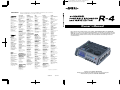
R-4
4-CHANNEL PORTABLE RECORDER and WAVE EDITOR
Edirol Corporation North America
425 Sequoia Drive, Suite 114, Bellingham, WA 98226
(360) 594-4276
For EU Countries
This product complies with the requirements of European Directive 89/336/EEC.
For the USA
FEDERAL COMMUNICATIONS COMMISSION
RADIO FREQUENCY INTERFERENCE STATEMENT
This equipment has been tested and found to comply with the limits for a Class B digital device, pursuant to Part 15 of the
FCC Rules. These limits are designed to provide reasonable protection against harmful interference in a residential
installation. This equipment generates, uses, and can radiate radio frequency energy and, if not installed and used in
accordance with the instructions, may cause harmful interference to radio communications. However, there is no guarantee
that interference will not occur in a particular installation. If this equipment does cause harmful interference to radio or
television reception, which can be determined by turning the equipment off and on, the user is encouraged to try to correct the
interference by one or more of the following measures:
– Reorient or relocate the receiving antenna.
– Increase the separation between the equipment and receiver.
– Connect the equipment into an outlet on a circuit different from that to which the receiver is connected.
– Consult the dealer or an experienced radio/TV technician for help.
This device complies with Part 15 of the FCC Rules. Operation is subject to the following two conditions:
(1) This device may not cause harmful interference, and
(2) This device must accept any interference received, including interference that may cause undesired operation.
204
*
Microsoft and Windows are registered trademarks of Microsoft Corporation.
206j
*
Windows® is known officially as: “Microsoft® Windows® operating system.”
207
*
Unauthorized changes or modification to this system can void the users authority to operate this equipment.
This equipment requires shielded interface cables in order to meet FCC class B Limit.
Apple and Macintosh are registered trademarks of Apple Computer, Inc.
209
*
Mac OS is a trademark of Apple Computer, Inc.
220
For Canada
*
All product names mentioned in this document are trademarks or registered trademarks of their respective owners.
234
NOTICE
This Class B digital apparatus meets all requirements of the Canadian Interference-Causing Equipment Regulations.
*
CompactFlash and
are trademarks of SanDisk Corporation and licensed by CompactFlash association.
235
*
Roland Corporation is an authorized licensee of the CompactFlash™ and CF logo (
236
AVIS
Cet appareil numérique de la classe B respecte toutes les exigences du Règlement sur le matériel brouilleur du Canada.
*
Fugue © 2005 Kyoto Software Research, Inc. All rights reserved.
fig.Fugue-logo.eps
) trademarks.
R-4_e.book 3 ページ 2005年2月10日
木曜日
午後3時36分
USING THE UNIT SAFELY
The
symbol alerts the user to important instructions
or warnings.The specific meaning of the symbol is
determined by the design contained within the
triangle. In the case of the symbol at left, it is used for
general cautions, warnings, or alerts to danger.
Used for instructions intended to alert
the user to the risk of death or severe
injury should the unit be used
improperly.
Used for instructions intended to alert
the user to the risk of injury or material
damage should the unit be used
improperly.
* Material damage refers
other adverse effects
respect to the home
furnishings, as well
animals or pets.
001
•
to damage or
caused with
and all its
to domestic
Before using this unit, make sure to read the
instructions below, and the Owner’s Manual.
................................................................................................
002c
•
The
symbol alerts the user to items that must never
be carried out (are forbidden). The specific thing that
must not be done is indicated by the design contained
within the circle. In the case of the symbol at left, it
means that the unit must never be disassembled.
Do not open (or modify in any way) the unit or its
AC adaptor.
The ● symbol alerts the user to things that must be
carried out. The specific thing that must be done is
indicated by the design contained within the circle. In
the case of the symbol at left, it means that the powercord plug must be unplugged from the outlet.
008e
•
................................................................................................
009
•
................................................................................................
003
•
Do not attempt to repair the unit, or replace parts
within it (except when this manual provides
specific instructions directing you to do so). Refer
all servicing to your retailer, the nearest Roland Service
Center, or an authorized Roland distributor, as listed on
the “Information” page.
Never use or store the unit in places that are:
• Subject to temperature extremes (e.g., direct
sunlight in an enclosed vehicle, near a heating
duct, on top of heat-generating equipment); or
are
• Damp (e.g., baths, washrooms, on wet floors); or are
• Humid; or are
• Exposed to rain; or are
• Dusty; or are
• Subject to high levels of vibration.
................................................................................................
007
•
Make sure you always have the unit placed so it is
level and sure to remain stable. Never place it on
stands that could wobble, or on inclined surfaces.
................................................................................................
008c
•
Be sure to use only the AC adaptor supplied with
the unit. Also, make sure the line voltage at the
installation matches the input voltage specified on
the AC adaptor’s body. Other AC adaptors may use a
different polarity, or be designed for a different voltage, so
their use could result in damage, malfunction, or electric
shock.
................................................................................................
Do not excessively twist or bend the power cord,
nor place heavy objects on it. Doing so can damage
the cord, producing severed elements and short
circuits. Damaged cords are fire and shock hazards!
................................................................................................
010
•
................................................................................................
004
•
Use only the attached power-supply cord. Also,
the supplied power cord must not be used with
any other device.
This unit, either alone or in combination with an
amplifier and headphones or speakers, may be
capable of producing sound levels that could cause
permanent hearing loss. Do not operate for a long period
of time at a high volume level, or at a level that is uncomfortable. If you experience any hearing loss or ringing in
the ears, you should immediately stop using the unit, and
consult an audiologist.
................................................................................................
011
•
Do not allow any objects (e.g., flammable material,
coins, pins); or liquids of any kind (water, soft
drinks, etc.) to penetrate the unit.
................................................................................................
012b
•
Immediately turn the power off, remove the AC
adaptor from the outlet, and request servicing by
your retailer, the nearest Roland Service Center, or an
authorized Roland distributor, as listed on the “Information” page when:
• The AC adaptor, the power-supply cord, or the plug has been
damaged; or
• If smoke or unusual odor occurs
• Objects have fallen into, or liquid has been spilled onto the unit;
or
• The unit has been exposed to rain (or otherwise has become
wet); or
• The unit does not appear to operate normally or exhibits a
marked change in performance.
................................................................................................
3
R-4_e.book 4 ページ 2005年2月10日
013
•
木曜日
午後3時36分
In households with small children, an adult should
provide supervision until the child is capable of
following all the rules essential for the safe operation of
the unit.
................................................................................................
014
•
Protect the unit from strong impact.
(Do not drop it!)
................................................................................................
015
•
Do not force the unit’s power-supply cord to share
an outlet with an unreasonable number of other
devices. Be especially careful when using extension
cords—the total power used by all devices you have
connected to the extension cord’s outlet must never
exceed the power rating (watts/amperes) for the
extension cord. Excessive loads can cause the insulation
on the cord to heat up and eventually melt through.
................................................................................................
016
•
Before using the unit in a foreign country, consult
with your retailer, the nearest Roland Service
Center, or an authorized Roland distributor, as listed on
the “Information” page.
................................................................................................
019
•
Batteries must never be recharged, heated, taken
apart, or thrown into fire or water.
108b
•
................................................................................................
109b
•
................................................................................................
•
................................................................................................
•
• Carefully follow the installation instructions for
batteries, and make sure you observe the correct
polarity.
2
• Avoid using new batteries together with used ones. In
addition, avoid mixing different types of batteries.
3
• Remove the batteries whenever the unit is to remain
unused for an extended period of time.
5
• If a battery has leaked, use a soft piece of cloth or paper
towel to wipe all remnants of the discharge from the
battery compartment. Then install new batteries. To
avoid inflammation of the skin, make sure that none of
the battery discharge gets onto your hands or skin.
Exercise the utmost caution so that none of the
discharge gets near your eyes. Immediately rinse the
affected area with running water if any of the discharge
has entered the eyes.
102c
6
................................................................................................
112
Always grasp only the plug on the AC adaptor
cord when plugging into, or unplugging from, an
outlet or this unit.
103b
•
At regular intervals, you should unplug the AC
adaptor and clean it by using a dry cloth to wipe
all dust and other accumulations away from its
prongs. Also, disconnect the power plug from the power
outlet whenever the unit is to remain unused for an
extended period of time. Any accumulation of dust
between the power plug and the power outlet can result in
poor insulation and lead to fire.
................................................................................................
104
•
Try to prevent cords and cables from becoming
entangled. Also, all cords and cables should be
placed so they are out of the reach of children.
................................................................................................
106
•
Never climb on top of, nor place heavy objects on
the unit.
................................................................................................
107c
•
Never handle the AC adaptor or its plugs with wet
hands when plugging into, or unplugging from, an
outlet or this unit.
................................................................................................
4
If used improperly, batteries may explode or leak
and cause damage or injury. In the interest of
safety, please read and observe the following
precautions (p. 25).
1
The unit and the AC adaptor should be located so
their location or position does not interfere with
their proper ventilation.
................................................................................................
Whenever you suspect the possibility of lightning
in your area, disconnect the AC adaptor from the
outlet.
111: Selection
101b
•
Before cleaning the unit, turn off the power and
unplug the AC adaptor from the outlet.
110b
................................................................................................
•
Before moving the unit, disconnect the AC adaptor
and all cords coming from external devices.
• Never keep batteries together with metallic objects such
as ballpoint pens, necklaces, hairpins, etc.
................................................................................................
•
Used batteries must be disposed of in compliance
with whatever regulations for their safe disposal
that may be observed in the region in which you
live.
................................................................................................
118a
•
Should you remove the ground terminal screw,
keep them in a safe place out of children’s reach, so
there is no chance of them being swallowed
accidentally.
................................................................................................
120
•
Always turn the phantom power off when
connecting any device other than condenser microphones that require phantom power. You risk causing
damage if you mistakenly supply phantom power to
dynamic microphones, audio playback devices, or other
devices that don’t require such power. Be sure to check
the specifications of any microphone you intend to use by
referring to the manual that came with it.
This instrument’s phantom power: 48V DC, 8 mA Max
(total of all channels must be 25 mA or less)
................................................................................................
R-4_e.book 5 ページ 2005年2月10日
木曜日
午後3時36分
Important Notes
291a
In addition to the items listed under “USING THE UNIT SAFELY” on page 3, please read and observe the following:
Power Supply: Use of Batteries
Maintenance
301
401a
• Do not connect this unit to same electrical outlet that is
being used by an electrical appliance that is controlled by
an inverter (such as a refrigerator, washing machine,
microwave oven, or air conditioner), or that contains a
motor. Depending on the way in which the electrical
appliance is used, power supply noise may cause this unit
to malfunction or may produce audible noise. If it is not
practical to use a separate electrical outlet, connect a power
supply noise filter between this unit and the electrical
outlet.
• For everyday cleaning wipe the unit with a soft, dry cloth
or one that has been slightly dampened with water. To
remove stubborn dirt, use a cloth impregnated with a mild,
non-abrasive detergent. Afterwards, be sure to wipe the
unit thoroughly with a soft, dry cloth.
302
• The AC adaptor will begin to generate heat after long
hours of consecutive use. This is normal, and is not a cause
for concern.
303a
• The use of an AC adaptor is recommended as the unit’s
power consumption is relatively high. Should you prefer to
use batteries, please use the alkaline or nickel metal
hydride type.
304a
• When installing or replacing batteries, always turn off the
power on this unit and disconnect any other devices you
may have connected. This way, you can prevent
malfunction and/or damage to speakers or other devices.
307
• Before connecting this unit to other devices, turn off the
power to all units. This will help prevent malfunctions
and/or damage to speakers or other devices.
Placement
351
• Using the unit near power amplifiers (or other equipment
containing large power transformers) may induce hum. To
alleviate the problem, change the orientation of this unit; or
move it farther away from the source of interference.
352a
• This device may interfere with radio and television
reception. Do not use this device in the vicinity of such
receivers.
352b
• Noise may be produced if wireless communications
devices, such as cell phones, are operated in the vicinity of
this unit. Such noise could occur when receiving or initiating a call, or while conversing. Should you experience
such problems, you should relocate such wireless devices
so they are at a greater distance from this unit, or switch
them off.
354a
• Do not expose the unit to direct sunlight, place it near
devices that radiate heat, leave it inside an enclosed
vehicle, or otherwise subject it to temperature extremes.
Excessive heat can deform or discolor the unit.
355b
• When moved from one location to another where the
temperature and/or humidity is very different, water
droplets (condensation) may form inside the unit. Damage
or malfunction may result if you attempt to use the unit in
this condition. Therefore, before using the unit, you must
allow it to stand for several hours, until the condensation
has completely evaporated.
402
• Never use benzine, thinners, alcohol or solvents of any
kind, to avoid the possibility of discoloration and/or deformation.
Repairs and Data
452
• Please be aware that all data contained in the unit’s
memory may be lost when the unit is sent for repairs.
Important data should always be backed up on a
CompactFrash, your computer, or written down on paper
(when possible). During repairs, due care is taken to avoid
the loss of data. However, in certain cases (such as when
circuitry related to memory itself is out of order), we regret
that it may not be possible to restore the data, and Roland
assumes no liability concerning such loss of data.
Memory Backup
501b
• The R-4 contains a battery that keeps the internal clock
running even when the power is turned off. When this
battery runs low, the message shown below will appear in
the display. Replace the battery as soon as possible, since
the clock will not keep the correct time if the battery is low.
To have the battery replaced, consult with your retailer, the
nearest Roland Service Center, or an authorized Roland
distributor, as listed on the “Information” page.
Int-Batt Low!
Additional Precautions
551
• Please be aware that the contents of memory can be
irretrievably lost as a result of a malfunction, or the
improper operation of the unit. To protect yourself against
the risk of loosing important data, we recommend that you
periodically save a backup copy of important data you
have stored in the unit’s memory on a CompactFrash or
your computer.
552
• Unfortunately, it may be impossible to restore the contents
of data that was stored on a hard disk, or a CompactFrash
once it has been lost. Roland Corporation assumes no
liability concerning such loss of data.
553
• Use a reasonable amount of care when using the unit’s
buttons, sliders, or other controls; and when using its jacks
and connectors. Rough handling can lead to malfunctions.
554
• Never strike or apply strong pressure to the display.
556
• When connecting / disconnecting all cables, grasp the
connector itself—never pull on the cable. This way you will
avoid causing shorts, or damage to the cable’s internal
elements.
5
R-4_e.book 6 ページ 2005年2月10日
木曜日
午後3時36分
Important Notes
558a
• To avoid disturbing your neighbors, try to keep the unit’s
volume at reasonable levels. You may prefer to use
headphones, so you do not need to be concerned about
those around you (especially when it is late at night).
559a
• When you need to transport the unit, package it in the box
(including padding) that it came in, if possible. Otherwise,
you will need to use equivalent packaging materials.
562
• Use a cable from Roland to make the connection. If using
some other make of connection cable, please note the
following precautions.
• Some connection cables contain resistors. Do not use
cables that incorporate resistors for connecting to this
unit. The use of such cables can cause the sound level to
be extremely low, or impossible to hear. For information on cable specifications, contact the manufacturer of the cable.
Before Using Cards
704
• Carefully insert the DATA card all the way in—until it is
firmly in place.
fig.M512-Insert
Precautions Regarding Setup and Use
812
• Certain hard disk setup procedures and usage conditions
may result in the corruption of recorded data, malfunctioning, or physical damage to the disk, so be sure to
observe the following precautions.
• Do not subject the hard disk to vibration or shock,
especially while the unit is in operation.
• Do not set up the unit in any location where it may be
affected by vibration from external sources, or on any
surface that is not stable and level.
• If the device includes a cooling fan, ensure that the fan
and the side panel air vents remain unobstructed.
• Do not leave the unit in any environment subject to
temperature extremes; for example, in a closed
automobile in summer or outdoors during winter.
• Do not use the unit in conditions of high temperature
and humidity or in any location subject to rapid
temperature changes.
• Do not unplug the power cord or switch off any circuit
breakers in the circuit to which the unit is connected
while the power is turned on.
Emergency Procedures
813
*
CompactFlash™
705
• Never touch the terminals of the DATA card. Also, avoid
getting the terminals dirty.
707
• This unit’s memory card slot accepts CompactFlash
memory cards. Microdrive storage media are not
compatible.
Handling Hard Disks
811
• Once a hard disk fails to function normally, all data that
has been stored on it could be destroyed.
All hard disks eventually wear out. We recommend that
you consider the hard disk not as a permanent storage site,
but as a place to store data temporarily. We also
recommend that you back up important performance and
image data that cannot be recorded again onto the external
media that is supported by your device. For instructions on
how to make such backups, refer to the owner’s manual for
your device.
Note that Roland assumes no liability whatsoever,
including monetary compensation, for the loss of any
recorded content in the event of the malfunction of, or
physical damage to the hard disk, or for any direct or
incidental damages resulting from the loss of such data.
The following procedures are to be used as emergency measures only, and are not recommended for normal operation.
• If the device fails to respond to operational commands or
does not complete operations, turn off the power. If the
power does not shut off following normal shutdown procedures, disconnect the power plug.
If the unit does not operate normally when the power is
turned on again, it may mean that the hard disk has been
damaged. In such instances, consult your dealer or the
nearest Roland Service Center. Note, however, that it may
not be possible to recover any data from the hard disk once
it has been lost.
Copyright
851
• Unauthorized recording, distribution, sale, lending, public
performance, broadcasting, or the like, in whole or in part,
of a work (musical composition, video, broadcast, public
performance, or the like) whose copyright is held by a third
party is prohibited by law.
852b
• When exchanging audio signals through a digital
connection with an external instrument, this unit can
perform recording without being subjected to some of the
restrictions of the Serial Copy Management System
(SCMS). This is because the unit is intended solely for
musical production, and is designed not to be subject to
restrictions as long as it is used to record works (such as
your own compositions) that do not infringe on the
copyrights of others. (SCMS is a feature that prohibits
second-generation and later copying through a digital
connection. It is built into MD recorders and other
consumer digital-audio equipment as a copyrightprotection feature.)
853
• Do not use this unit for purposes that could infringe on a
copyright held by a third party. We assume no responsibility whatsoever with regard to any infringements of
third-party copyrights arising through your use of this
unit.
6
R-4_e.book 7 ページ 2005年2月10日
木曜日
午後3時36分
Contents
Checking the included items ...... 8
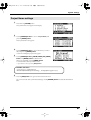
Application guide ....................75
Introducing the R-4 ................... 9
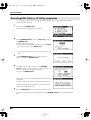
Connecting an external mic
for CD-quality stereo recording ...................75
Recording birdsongs outdoors .....................76
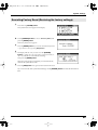
Recording audio while shooting video .......77
Recording audio memos using just the R-477
Simultaneously recording
environmental sounds (ambience)...............78
Simultaneously recording
at different input levels .................................78
The R-4’s controls and connectors .................9
Display.............................................................18
What is a project? ...........................................21
Getting ready to use the R-4 ... 23
Basic connection examples ...........................23
Connecting the AC adaptor and turning
the power on ...................................................24
Installing batteries and turning
the power on ...................................................25
Recording ............................... 27
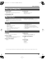
Messages ................................79
Troubleshooting.......................80
Computer-related problems .........................80
Recording-related problems .........................80
Playback-related problems ...........................82
Problems with the R-4’s operation...............83
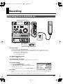
Recording from a connected mic .................27
Recording from the internal mics ................30
Recording digital audio from a digital device
..........................................................................31
Recording analog audio ................................32
Main specifications ..................84
Playing back........................... 34
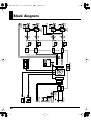
Block diagram .........................86
Connections before playback .......................34
Settings before playback ...............................36
Playing back....................................................38
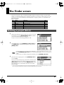
The Finder screen .................... 41
Deutsch.........................................................
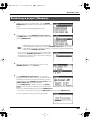
Selecting a project (Select).............................41
Deleting a project (Delete) ............................42
Renaming a project (Rename) ......................43
Copying a project (Copy)..............................44
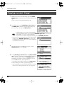
Moving a project (Move)...............................45
Creating a new folder (Make Folder)..........46
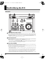
Beschreibung des R-4 ..............88
Editing .................................... 48
Editing procedure ..........................................48
Effects setting .......................... 55
Effects...............................................................56
Using effects....................................................58
Français ........................................................
Présentation du R-4 .................94
Italiano..........................................................
Presentazione dell’R-4 ...........100
Español .........................................................
Presentación del R-4 ..............106
System settings ....................... 60
System Menu ..................................................60
Example operations .......................................65
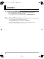
Appendix................................ 70
Handling memory cards ...............................70
Connection to a computer.............................72
Connecting a video device
that has a LANC connector ..........................74
Index ....................................112
7
R-4_e.book 8 ページ 2005年2月10日
木曜日
午後3時36分
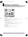
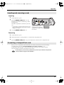
Checking the included items
The R-4 comes with the following items. Immediately after opening the package, please check that you have
all of these items. If any items are missing, please contact the dealer where you purchased the R-4.
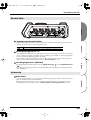
■ R-4
fig.R-4.eps_50
■ AC adaptor
This AC adaptor is designed specifically for the R-4. Do not attempt to use any other adaptor with the R-4.
“Connecting the AC adaptor and turning the power on” (p. 24)
■ USB cable (1 meter)
You can use this cable to connect the R-4 to the USB connector of your computer.
“Connection to a computer” (p. 72)
* If the AC adaptor or USB cable becomes damaged or if you need a replacement for any reason, please contact one of
the Service Centers listed in the “Information” section at the end of this manual.
* Don't remove the ferrite core that's attached to the USB cable.
■ Carrying case
You can use this case to protect the R-4 while it is being transported or stored.
■ Owner’s manual
This is the document you’re reading. Keep it at hand for easy reference.
8
R-4_e.book 9 ページ 2005年2月10日
木曜日
午後3時36分
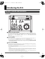
Introducing the R-4
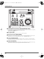
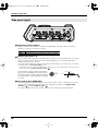
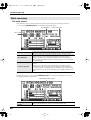
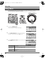
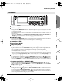
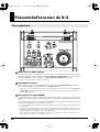
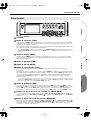
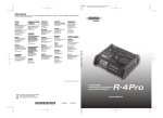
The R-4’s controls and connectors
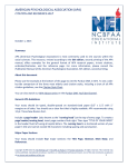
Top panel
fig.panel-1.eps_50
1
1
2
3
7
2
4
8
5
6
9
13
16
10
17
11
12
14
1
15
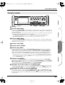
Internal mics [MIC-L, MIC-R]
These are stereo mics built into the R-4. The audio entering MIC-L is recorded on the 1L channel, while
audio picked up by MIC-R is recorded on the 1R channel. If you’re recording via the internal mics, set the
System Settings menu item Recording Setup to Int-Mic. For details, refer to “Recording from the internal
mics” (p. 30).
* Don’t connect anything to input jacks you’re not using.
2
Internal speakers
These are built-in speakers for monitoring. If you want sound to be heard from the internal speakers, set
the System Settings menu item Speaker to ON. For details, refer to “Playing back” (p. 34).
* No sound will be heard from the internal speakers if you’ve connected headphones to the Headphone jack ( 37 ).
Nor will sound be heard from the internal speakers while recording or in recording-standby mode; this prevents
acoustic feedback from occurring.
3
Power switch [POWER]
This turns the power on/off. To turn the power on or off, press and hold the power switch for about two
seconds. The power switch is lit green when the power is on.
Don’t turn the power off during recording or playback. Before you turn off the power, you must make sure
that recording or playback is stopped.
* If you accidentally turn off the power during recording, the data that was being recorded will not be stored on the
hard disk.
* The hard disk may be damaged if you turn off the power of the R-4 while data is being read from or written to the
hard disk (such as during recording or playback). You must also be careful not to turn off the power while data is
being transferred between the hard disk and the CompactFlash card.
* Never turn off the power while the R-4’s display indicates Now Connecting... or Now Processing! Doing so will
cause the R-4 to become unstable, and could even damage the internal hard disk.
9
R-4_e.book 10 ページ 2005年2月10日
木曜日
午後3時36分
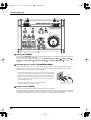
Introducing the R-4
fig.panel-1.eps_50
1
1
2
3
7
2
4
8
5
6
9
13
16
10
17
11
12
14
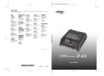
4
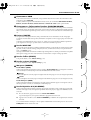
15
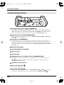
Hold switch [HOLD]
By selecting the HOLD ON position, you can disable the panel buttons so that unwanted operations will not
occur if a button is pressed accidentally.
However, even if this switch is set to HOLD ON, the phantom power switches 5 , limiter switch 6 ,
input level select switches 38 , Input level knobs 25 , and Monitor level knob 26 will still be
operable.
5
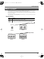
Phantom power switches [PHANTOM POWER]
These switch the phantom power on/off for the XLR type connectors of the combo input jacks located on
the right panel. Since separate switches are provided for channels 1/2 and channels 3/4, you can turn
phantom power on/off separately for these channels.
fig.jack-type
* Always turn the phantom power off when connecting any device other than
condenser microphones that require phantom power. You risk causing damage
if you mistakenly supply phantom power to dynamic microphones, audio
playback devices, or other devices that don’t require such power. Be sure to
check the specifications of any microphone you intend to use by referring to
the manual that came with it.
This instrument’s phantom power: 48 V DC, 8 mA Max
(total of all channels must be 25 mA or less)
6
XLR plug
TRS phone
Phone plug
plug
(unbalanced) (balanced)
Limiter switch [LIMITER]
This is an on/off switch for an input level limiter in the analog circuitry.
When the input level is too high, the limiter compresses the input level appropriately to prevent distortion.
The limiter switch turns limiting on/off for all channels 1–4 together. However, the input level is detected
separately for each channel. You cannot turn the limiter on/off separately for each channel.
10
R-4_e.book 11 ページ 2005年2月10日
木曜日
午後3時36分
Introducing the R-4
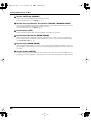
7
Wave edit button [WAVE EDIT]
This button takes you to Wave Edit mode, where you can edit the waveform using operations such as Trim,
Divide, Combine, and Merge. For details, refer to “Editing” (p. 48).
You won't be able to enter Wave Edit mode during playback or recording, or if the R-4’s hard disk contains
no files that the R-4 can handle.
WAV files are the only type of files that the R-4 can handle.
8
Effect button [EFFECTS]
This button takes you to Effect mode, where you can make effect settings.
For details, refer to “Effects setting” (p. 55).
9
System button [SYSTEM]
This button takes you to a mode where you can make various settings for the R-4.
For details, refer to “System settings” (p. 60).
10
Marker [MARKER]
Clear button [CLEAR]
This button deletes a marker you assigned using the Mark button. Markers will be deleted successively,
starting at the marker located immediately before the current location.
button
This button moves you to the marker that is immediately before the current location (the previous marker).
button
This button moves you to the marker that is immediately after the current location (the next marker).
Mark button [MARK]
By pressing this button you can assign a marker to a desired location in the project file. Markers are
numbered sequentially starting at the beginning of the project.
11
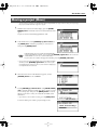
A-B Repeat button [A-B REPEAT]
This button lets you repeatedly play back the region between two points (A and B) in the project. Simply
assign marker A and marker B while the project is playing, and playback will repeat between markers A
and B.
fig.repeat-a
1. During playback, press the A-B Repeat button once.
That point becomes the beginning (marker A) of repeat playback.
A
fig.repeat-b
2. Press the A-B Repeat button once again. That point will be the end
(marker B) of repeat playback.
A
B
A
B
fig.repeat-ab
The region you specified in steps 1 and 2 will play repeatedly. To cancel repeat
playback, press the A-B Repeat button once again.
12
Display button [DISPLAY]
This button switches the contents of the R-4’s display.
For details, refer to “Display” (p. 18).
11
R-4_e.book 12 ページ 2005年2月10日
木曜日
午後3時36分
Introducing the R-4
fig.panel-1.eps_50
1
1
2
3
7
2
4
8
5
6
9
13
16
10
17
11
12
14
13
15
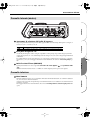
Cursor/Monitor Select buttons [CURSOR/MONITOR SELECT]
Use these buttons to select items shown in the display. When you’re in the main screen, you can press the
up/down buttons to select the channel that you want to monitor.
For details, refer to “Display” (p. 18).
14
Exit button [EXIT]
Use this button to return to the previous screen or to cancel an operation.
15
Enter/Finder button [ENTER/FINDER]
Use this button to confirm a setting or finalize a value. You can also press this when you want to use the
Finder function. For more about the Finder function, refer to “The Finder screen” (p. 41).
16
Scrub dial [SCRUB/VALUE]
Use this dial to select among items for which settings are made, or to modify a value. While stopped or
when playback is paused, you can turn the scrub dial to move the current location forward or backward.
17
Shuttle dial [SHUTTLE]
While the project is playing, turn this dial clockwise to play rapidly forward, or counterclockwise to play
rapidly backward. When the project is stopped, this dial advances the time counter.
12
R-4_e.book 13 ページ 2005年2月10日
木曜日
午後3時36分
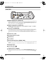
Introducing the R-4
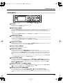
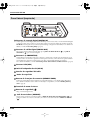
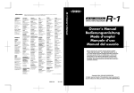
Front panel
fig.panel-2.eps_50
18
19
20
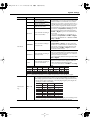
21
25
18
22
23
24
26
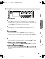
Display
This shows various information about the R-4’s status.
For details, refer to “Display” (p. 18).
19
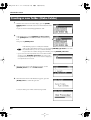
PREV button [PREV]
Pressing the PREV button while a project is playing or stopped will take you to the beginning of the project
(00:00:00). Pressing this button at the beginning of a project will take you to the preceding project.
You can also press and hold down this button to rewind. This is available both while playing and while
stopped.
* If the system setting Player Setup parameter Play Mode is set to Single, you can't move to the previous or next
project during playback.
20
NEXT button [NEXT]
Pressing the NEXT button will take you to the next project. You can also press and hold this button to fastforward. This is available both while playing and while stopped.
* If the system setting Player Setup parameter Play Mode is set to Single, you can't move to the previous or next
project during playback.
21
Stop button [STOP]
This button stops playback or recording. If you press the STOP button during playback, the counter will
maintain the time at which you pressed the STOP button.
22
Pause button [PAUSE]
This button pauses playback or recording.
23
Play button [PLAY]
This button starts playback. The PLAY button is lit blue during playback.
During playback, you can press the PLAY button once again to play at double-speed. During doublespeed playback, press the PLAY button once again to return to normal playback. During double-speed
playback, the lower part of the display will indicate PLAY X2. Double-speed playback will change the
pitch.
* If you want to turn off the double-speed playback feature, go to the System Settings menu and in Player Setup,
turn X2 Play OFF. For details, refer to “2 Player Setup” (p. 62).
24
Record button [REC]
Recording will begin immediately when you press the REC button. The REC button is lit red during
recording. If you hold down the PAUSE button and press the REC button, the REC button will blink
red, and the R-4 enters recording-standby mode. Recording will begin when you then press the REC
button or 22 PAUSE button.
25
Input level knobs 1–4 [INPUT GAIN]
These knobs adjust the input level of combo input jacks 1–4 ( 39 ). Input levels of the internal mics
( 1 ) are adjusted by knob 1 (MIC-L) and knob 2 (MIC-R).
26
Monitor level knob [MONITOR]
This adjusts the output volume of the internal speakers ( 2 ) and the headphone jack ( 37 ).
You can’t adjust the volume of the line output jacks ( 40 ). If you need to adjust the volume of the line
output jacks, adjust the controls of the external speakers or playback system connected to the line output
jacks.
13
R-4_e.book 14 ページ 2005年2月10日
木曜日
午後3時36分
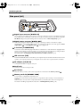
Introducing the R-4
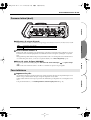
Side panel (left)
29
30
31
27
33
28
27
32
34
35
36
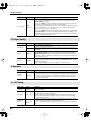
37
Digital input connector [DIGITAL IN]
If you want to record a digital signal, connect a coaxial-type cable to this connector. The digital input signal
is recorded in stereo on channels 1L and 1R. If you want to record in monaural, you’ll need to change the
Rec Mode setting in the System Settings menu. For details, refer to “1 Recording Setup” (p. 60).
28
Digital output connector [DIGITAL OUT]
This connector outputs a digital signal. You can use a coaxial-type cable to connect this to a digital
recording device such as a DAT or MD recorder. This connector provides the same audio signal as the line
output jacks ( 40 ) and headphone jack ( 37 ), but in digital form.
29
L connector [L-CONNECTOR]
You can use a stereo mini-mini-plug LANC cable to connect this to a video device that is equipped with a
LANC connector. When you begin recording on your video device, the R-4 will begin recording in tandem.
When you stop recording on your video device, the R-4 will also stop recording.
For details, refer to “Connecting a video device that has a LANC connector” (p. 74).
30
USB connector [USB]
Use the included USB cable to connect this to your computer. Projects recorded on the R-4 can be moved or
copied to your computer. Files from your computer can also be moved or copied to the R-4’s hard disk.
31
AC adaptor jack [DC IN]
Connect the included AC adaptor to this jack.
32
Cord hook
Use this to secure the AC adaptor cable.
33
Eject button
Press this when you want to remove the CompactFlash card inserted in the memory card slot 34 .
34
Memory card slot [MEMORY CARD]
You can insert a CompactFlash card into this slot.
Projects you record on the R-4 can be copied to a CompactFlash card for backup or to transfer them to a
computer.
The R-4 is able to use only TYPE 1 CompactFlash memory cards. Microdrive cards are not supported.
For details on handling CompactFlash cards, refer to “Handling memory cards” (p. 70).
14
R-4_e.book 15 ページ 2005年2月10日
木曜日
午後3時36分
Introducing the R-4
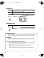
35
Grounding terminal
Depending on the circumstances of a particular setup, you may experience a discomforting sensation, or
perceive that the surface feels gritty to the touch when you touch this device, microphones connected to it,
or the metal portions of other objects. This is due to an infinitesimal electrical charge, which is absolutely
harmless. However, if you are concerned about this, connect the ground terminal (see figure) with an
external ground. When the unit is grounded, a slight hum may occur, depending on the particulars of your
installation. If you are unsure of the connection method, contact the nearest Roland Service Center, or an
authorized Roland distributor, as listed on the “Information” page.
Unsuitable places for connection
• Water pipes (may result in shock or electrocution)
• Gas pipes (may result in fire or explosion)
• Telephone-line ground or lightning rod (may be dangerous in the event of lightning)
36
Security Slot [
]
http://www.kensington.com/
37
Headphone jack [PHONES]
Connect a set of headphones to this jack. Use the monitor level knob ( 26 ) to adjust the volume. If you
connect headphones, sound will not be heard from the internal speakers ( 2 ).
15
R-4_e.book 16 ページ 2005年2月10日
木曜日
午後3時36分
Introducing the R-4
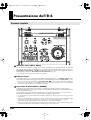
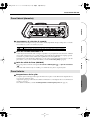
Side panel (right)
fig.panel-3.eps_50
40
38
38
39
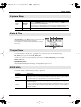
38
Input level select switches
Set these switches to either the MIC or LINE position depending on the type of device connected to
channels 1/L and 2/R or channels 3/L and 4/R.
MIC
LINE
39
If a mic is connected
If an audio device is connected via an analog connection
Combo input jacks 1–4
These are analog audio input jacks compatible with mic preamps. They accept either XLR or 1/4” phone
plugs; you can use whichever is most convenient for the equipment you’re connecting. Balanced or
unbalanced signals can be connected.
You can use combo input jacks 1–4 as four channels of monaural input or as two stereo pairs, 1/2 and 3/4.
For details, refer to “1 Recording Setup” (p. 60).
* The XLR type jacks can provide 48 V phantom power, allowing you to connect phantom-powered condenser mics.
In this case, turn on the phantom power switch ( 5 ).
fig.XLR-TRS
This instrument is equipped with balanced (XLR/
TRS) type jacks. Wiring diagrams for these jacks are
shown below. Make connections after first checking
the wiring diagrams of other equipment you intend
to connect.
40
GND(SLEEVE)
1:GND
2:HOT
3:COLD
HOT(TIP)
COLD(RING)
Line output jacks [LINE OUT]
These jacks output an analog audio signal. You can use RCA phono cables to connect them to powered
speakers, audio equipment, a mixer, etc. These jacks output the same signal as the digital output
connector ( 29 ) and the headphone jack ( 37 ).
The nominal output level is fixed at -10 dBV, and the volume of these jacks cannot be adjusted.
16
R-4_e.book 17 ページ 2005年2月10日
木曜日
午後3時36分
Introducing the R-4
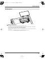
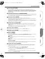
Bottom panel
41
41
Battery compartment
Install batteries here if you want to operate the R-4 on battery power.
The orientation in which you must insert the batteries is shown on the side of the battery compartment.
Be sure to observe the correct polarity when installing the batteries.
If you’re using the AC adaptor, there’s no need to install batteries.
Make sure to switch off the R-4’s power before you change from AC adaptor operation to battery operation,
or vice versa.
For details, refer to “Installing batteries and turning the power on” (p. 25).
17
R-4_e.book 18 ページ 2005年2月10日
木曜日
午後3時36分
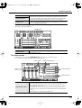
Introducing the R-4
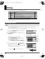
Display
While playing or stopped
The main screen
The R-4’s main screen provides information about the project and the operational status of the R-4.
You can press the [DISPLAY] button to switch the contents of the display.
fig.play-disp.eps
Project name
Progress bar
Total time
Time
counter
Level scale
dBFS
Sampling frequency
Channel
names
Sample size
(bit depth)
Marker indicators
Clip level indicators
Output
assignments
Power source
Channel level meters
Status indication
Project name
Time counter
Progress bar
Total time
Level scale
Clip level indicators
Channel level meters
Channel names
Output assignments
Sampling frequency
Sample size
Marker indicators
18
Date and time
Output level meters
Clip level indicators
Indicates the name of the project. If you copy WAV files from your computer
via USB to the R-4’s internal hard disk, this will show the file name. File names
containing double-byte characters (e.g., Japanese) will not be displayed correctly, but they can be played.
Indicates the time that has elapsed from the beginning of the project to the
current location. Indicated in terms of hours: minutes: seconds.
Indicates the current playback location relative to the entire project.
Indicates the total time of the entire project.
Shows the audio level of each channel in real time. The markings are relative
to 0 dBFS (Full Scale) of the digital signal. For example, 12 means -12 dBFS. C
is clipping level (0 dBFS).
This area shows up to four channel names. If you’re using one stereo channel,
this will indicate 1L and 1R. If you’re using two stereo channels, this will indicate 1L, 1R, 2L, 2R.
For a monaural project, this area will show 1, 2, 3, and 4 according to the number of channels.
These show how the audio of each channel is assigned to the L/R output
channels. L means that the audio is assigned to the left channel, R to the right
channel, and LR to both left and right channels. Channels for which no indication appears will not be output. When you're in the main screen, you can
press the [CURSOR] up/down buttons to select the channel that you want to
monitor.
The output is sent to the PHONES jack, line output jacks, and digital output
connector.
Indicates the sampling frequency and sample size (bit depth) of the currently
selected project.
The number at the left indicates the marker located immediately before the
current time counter value. The number at the right indicates the total number
of markers assigned in the currently selected project.
R-4_e.book 19 ページ 2005年2月10日
木曜日
午後3時36分
Introducing the R-4
Output level meters
Clip level indicators
Power source
These are the output level meters. They show the final output levels of the L
and R channels, to which the various channels have been mixed. You can use
the monitor level sliders of the mixer screen to adjust the level of each channel.
From the left, the level meter is calibrated at -36, -24, -12, and -6 dBFS.
Indicates how power is being supplied to the R-4. The plug icon is shown if
power is being supplied by the AC adaptor, and the battery icon is shown if
power is being supplied by batteries.
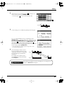
In the main screen, you can press the [DISPLAY] button to switch the progress bar area so it shows the
remaining project time (REMAIN).
fig.play-disp2.eps
Remaining time
Remaining time
During playback, this indicates the remaining time from the current location
to the end of the project.
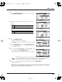
The mixer screen
From the main screen, press the [DISPLAY] button twice to move to the Mixer screen.
This screen lets you adjust the volume balance for monitoring.
fig.play-disp3.eps
Channel names
Channel level
sliders
Monitor output indicators
Channel level meters
Output level meters
Channel level sliders
Use these to adjust the playback level of each channel. Use the left/right
[CURSOR/FINDER] buttons to select a slider, and turn the [SCRUB/VALUE]
dial to adjust the value. Each slider provides adjustment within the range 0–
120. The default value is 100.
* The settings are not stored in the project; they are remembered by the R-4
itself. When you turn off the power, the settings will revert to their default
values.
* These settings do not affect the recording levels.
19
R-4_e.book 20 ページ 2005年2月10日
木曜日
午後3時36分
Introducing the R-4
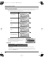
While recording
The main screen
The R-4’s main screen provides information about the project and the operational status of the R-4.
You can press the [DISPLAY] button to switch the contents of the display.
Recordable time
Total recording time
Time counter
Time counter
Recordable time
Total recording time
Indicates the elapsed time from the beginning of the project you’re recording
until the current location. Indicated in terms of hours: minutes: seconds.
During recording, this indicates the remaining time that recording to the hard
disk can take place. The remaining time will depend on the sampling
frequency (Sample Freq.), sample size (Rec Bit), and recording mode (Rec
Mode) settings. The indication shows how much longer you can record with
the current settings.
Indicates the total time from the beginning of recording to the current
location.
* Even if you record continuously, another new project will be created
automatically when the project reaches 2 GB in size, and recording will
continue. Even for a recording that spans multiple projects in this way, the
elapsed time since you first pressed the [REC] (record) button will be shown
here.
* For an explanation of the other indications, refer to “While playing or stopped” (p. 18).
From the main screen, you can press the [DISPLAY] button to make the recordable time area show the
remaining hard disk capacity instead.
Remaining hard disk capacity
Remaining hard disk
capacity
20
Indicates the remaining free capacity on the internal hard disk.
R-4_e.book 21 ページ 2005年2月10日
木曜日
午後3時36分
Introducing the R-4
What is a project?
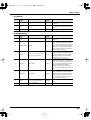
On the R-4, the data that you record and play back is handled as “projects.” On the hard disk, each project
actually consists of a folder with one or more files, in the structure shown below.
If you connect the R-4 to your computer, you’ll be able to see how these folders and files are organized.
However, if you change, delete, or rename the files within a project, the R-4 may be unable to play back that
project. Please use caution.
In the system settings, the Recording Setup parameter Rec Mode (p. 61) lets you specify the type of project
you want to record.
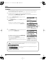
Monaural projects
Type
Structure
If there is only one channel, a monaural WAV file will be created with a name consisting of the project name plus an extension of .wav.
If there are 2–4 channels, a folder will be created with a name consisting of the project
name plus an extension of .pjt, and within that folder will be created monaural WAV
files with names consisting of the channel number plus an extension of .wav.
MONOx1
MONOx2
MONOx3
MONOx4
fig.project-M1.eps
Project Name
ABC-1.wav
ABC-1.
wav
(MONO)
ABC-2.pjt
1.wav
2.wav
(MONO)
(MONO)
MONOx2
MONOx1
Project Name
ABC-4.pjt
ABC-3.pjt
1.wav
2.wav
3.wav
(MONO)
(MONO)
(MONO)
MONOx3
1.wav
2.wav
3.wav
4.wav
(MONO) (MONO) (MONO) (MONO)
MONOx4
21
R-4_e.book 22 ページ 2005年2月10日
木曜日
午後3時36分
Introducing the R-4
Stereo projects
Type
STEREOx1
STEREOx2
Structure
If there is only one channel, a stereo WAV file will be created with a name consisting
of the project name plus an extension of .wav.
If there are two channels, a folder will be created with a name consisting of the project
name plus an extension of .pjt, and within that folder will be created stereo WAV files
with names consisting of the channel number plus an extension of .wav.
fig.project-S1.eps
Project Name
ABC-2.pjt
ABC-6.pjt
ABC-5.wav
ABC-5
.wav
1.wav
2.wav
(STEREO)
(STEREO)
(STEREO)
STEREOx1
STEREOx2
Four-channel projects
Type
4CH
ABC-7.wav
Structure
A four-channel WAV file will be created with a name consisting of the project name
plus an extension of .wav.
Project Name
ABC-7.
wav
* If you want to load such files into your computer, make sure
that your waveform editing software supports four-channel
files.
(4CH)
4CH
Limitations on file size
The R-4 can handle files up to 2 GB in size. If the file size reaches 2 GB during recording, the file will be
closed. Then, a new file will be created and recording will continue. When you finish recording, these files
will appear as separate projects.
About BWF
Each WAV file within a project is in BWF format. In addition to the conventional WAV data, the file
contains information about the recording time, recorder (EDIROL R-4), and marker data. Of course, these
files can be loaded into players or waveform editing software in the same way as conventional WAV files.
Caution when copying files from your computer
Please note the following cautions when copying files from your computer into the R-4’s internal hard disk.
• The R-4 can only record linear PCM WAV files at sampling frequencies of 44.1, 48, or 96 kHz and bit
depths of 16 or 24 bits. It cannot play back any other type of file.
• File names and folder names containing double-byte characters (e.g., Japanese) will not be displayed
correctly.
• Any files other than WAV files cannot be recognized by the R-4, and will be ignored.
• Files beginning with “.” (dot) will be ignored.
• You must not copy files larger than 2 GB into the R-4’s internal hard disk. Doing so will make the R-4’s
operation unstable, and in the worst case might even damage the files in the internal hard disk.
22
R-4_e.book 23 ページ 2005年2月10日
木曜日
午後3時36分
Getting ready to use the R-4
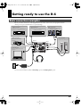
Basic connection examples
Before you make connections to other equipment, turn down the volume of all your equipment and turn
off the power to prevent malfunctions or speaker damage.
fig.basic.eps
Digital connections
Equipment that has a digital input jack
Digital connection
Analog connection
Equipment that has a digital output jack
Equipment that has a line input jack
MD player for recording/Amplified speakers, etc.
DIGITAL IN
Amplified speakers/Mixers
CD/MD player for playback
DIGITAL OUT
LINE IN
LANC connection
Video camera with a LANC
connector
Mic connection
Dynamic mic/Condenser mic
DIGITAL IN
LINE OUT
LANC
DIGITAL OUT
L-CONNECTOR
USB
USB connection
Personal computer with a USB
connector
USB
DC IN
PHONES
Headphones
AC outlet
AC adaptor
For more about connections, refer to “Recording” (p. 27) and “Playing back” (p. 34).
23
R-4_e.book 24 ページ 2005年2月10日
木曜日
午後3時36分
Getting ready to use the R-4
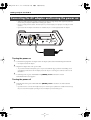
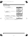
Connecting the AC adaptor and turning the power on
* After you’ve made connections correctly, you must turn on the power using the steps below. If you don’t follow the
correct order, you may cause malfunctions or damage your speakers.
* Due to a circuitry protection feature, this unit requires a few moments after power-up before it is ready for normal
operation.
* If you connect the AC adaptor when batteries are installed, the power will be supplied from the AC adaptor.
fig.adaptor.eps
Turning the power on
1
Connect the DC plug of the AC adaptor to the AC adaptor jack located on the left side panel of the R-4.
* Use only the included AC adaptor.
2
Plug the AC adaptor into an AC power outlet.
* To prevent the inadvertent disruption of power to your unit (should the plug be pulled out accidentally), and to
avoid applying undue stress to the AC adaptor jack, anchor the power cord using the cord hook, as shown in the
illustration.
3
To turn the power on, press and hold the R-4’s [POWER] switch for about two seconds.
Wait until the main screen appears.
Turning the power off
1
From the main screen, press and hold the R-4’s [POWER] switch for about two seconds to turn the
power off.
* If you disconnect or reconnect the AC adaptor, the power will turn off even if batteries are installed. Please turn off
the power on the R-4 itself before you change between AC adaptor power and battery power.
24
R-4_e.book 25 ページ 2005年2月10日
木曜日
午後3時36分
Getting ready to use the R-4
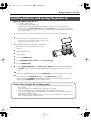
Installing batteries and turning the power on
Types of batteries you can use
• AA alkaline batteries (LR6)
• AA nickel metal-hydride (HR15/51)
(The R-4 cannot recharge nickel metal-hydride batteries. You’ll need to use a separate charger.)
* You must set the R-4’s System Settings menu item “5 System Setup” (p. 63) to specify the type of batteries
you’ve installed. The R-4 will not operate correctly if you’ve specified a battery type that does not match the batteries
you’ve actually installed.
1
2
Make sure that the R-4 is turned off, and disconnect the AC adaptor from the AC adaptor jack.
Detach the battery cover from the bottom panel of the R-4.
* When turning the unit upside-down, handle with care to avoid
dropping it, or allowing it to fall or tip over.
3
4
5
6
7
8
9
10
11
Insert eight AA batteries into the battery compartment,
making sure to observe the correct polarity (+ and symbols).
Replace the battery cover.
Turn on the R-4.
Press the [SYSTEM] button.
Use the [CURSOR] up/down buttons to select 5 System Setup.
Press the [ENTER] button.
Using the [SCRUB/VALUE] dial, set the Battery Type to Alkaline if you’ve installed alkaline batteries,
or to Ni-MH if you’ve installed nickel metal-hydride batteries. The setting is activated as soon as you
select it.
When you’ve finished making settings, press the [EXIT] button.You’re returned to the previous screen.
When you’re back in the System Menu screen, press the [EXIT] button once again.
Although the indication [ENTER] will be blinking in the display, if you don’t need to make additional
settings, press the [EXIT] button to return to the main screen.
Caution when using the R-4 on battery power
• If you operate on battery power for an extended time, the batteries will become hot. Be careful not to
burn yourself.
• We recommend that you use alkaline batteries, which have a longer life.
• Don’t mix new batteries with used batteries, and don’t mix batteries of differing types.
• If you won’t be using the R-4 for an extended time, we recommend that you remove the batteries to
prevent leakage or other accidents.
• When using a USB cable to connect the R-4 to your computer, you must use the AC adaptor to prevent
the loss of power while the connection is active.
25
R-4_e.book 26 ページ 2005年2月10日
木曜日
午後3時36分
Getting ready to use the R-4
Battery status indication
If you’re using the R-4 on battery power, a battery icon is shown in the lower right of the display. As the
battery runs down, the battery icon will change as follows.
Remaining amount
Display
Level 4 (sufficient)
Level 3
Level 2
Level 1
Level 0 (little remaining)
fig.bat-caution.eps
When the battery reaches Level 0, the message shown will appear.
Replace the batteries as soon as possible.
If you continue using the R-4 when the batteries have run low, the
screen shown here will appear, and then the power will
automatically turn off shortly thereafter.
Battery life
(When using alkaline batteries, 44.1 kHz, 16-bit, stereo, phantom power off)
Continuous playback
Continuous recording
approximately 3.5 hours
approximately 2 hours
* The values for battery life shown above are only approximate; they will vary depending on your system and
conditions of use.
* The life of the battery will be shortened if you leave the display backlighting turned on or if you make heavy use of
effects. There is a System setting that allows you to specify the length of time that the backlight is to remain on. For
details, refer to “4 LCD Setup” (p. 62).
26
R-4_e.book 27 ページ 2005年2月10日
木曜日
午後3時36分
Recording
Recording from a connected mic
Here’s how to record an audio source from a mic connected to the R-4’s combo input jack.
fig.mic-1.eps
Turn this ON
if you're using a
condenser mic.
Set to MIC
Adjust the
input level
● Connections
Connect your mic to the combo input jack.
If you’re monitoring through external speakers, acoustic feedback (a screech or whine) may occur,
depending on the position of the mic relative to the speakers. If this occurs, take the following actions.
1. Point the mic in a different direction
2. Move the mic away from the speakers
3. Lower the monitoring volume
● Input level select switch
Set this to the MIC position.
● Phantom power switch
If you’ve connected a phantom-powered condenser mic, turn this ON.
fig.input-analog.eps
● System settings
Press the R-4's [SYSTEM] button.
In 1 Recording Setup, set Input Select to Analog.
Set the other items in 1 Recording Setup as appropriate for the
recording you want to make.
* For more about system settings, refer to “System settings” (p. 60).
● Limiter
Turn this ON if you want to prevent unexpectedly loud sounds or strong attacks from producing clipping
noise.
The limiter threshold is -10 dB relative to digital full scale, and the compression ratio is 1:3.
27
R-4_e.book 28 ページ 2005年2月10日
木曜日
午後3時36分
Recording
● Input level knobs
These knobs adjust the input levels.
If you’re recording in stereo, these knobs control the following signals.
Channel 1
Channel 2
Channel 3
Channel 4
STEREO 1 L-channel
STEREO 1 R-channel
STEREO 2 L-channel
STEREO 2 R-channel
INPUT GAIN 1 knob
INPUT GAIN 2 knob
INPUT GAIN 3 knob
INPUT GAIN 4 knob
Adjusting the input level
1. Hold down the [PAUSE] button and press the [REC] (record) button.
The R-4 will enter recording-standby mode. In recording-standby mode, the [REC] (record) button will
blink, and the display will indicate REC STANDBY.
2. Play sound into the microphone at the actual volume that you expect to record.
3. Gradually turn the input level knob toward the right.
4. Adjust the level so that the level meter shown in the display
reaches a point slightly before C (clip level). If the recording
level is too low, quiet sounds will not be recorded. If the
recording level is too high, soft sounds will be distorted,
producing a crackling noise in the recording.
* The level meter indicates the clip level (C) at 0 dBFS (FS = full scale). For
example, 12 indicates -12 dBFS.
level meter (dBFS)
● Record button [REC]
If you want to begin recording immediately, press the [REC] (record) button. Recording will begin.
Recording-standby
If you want to put the R-4 in recording-standby mode so that
you can prepare for recording, hold down the [PAUSE]
button and press the [REC] (record) button.
Recording-standby
In recording-standby mode, the [REC] (record) button will blink
and the display will indicate REC PAUSE.
Recording will begin immediately when you press the [REC]
(record) button or the [PAUSE] button in recording-standby
mode or while paused.
28
R-4_e.book 29 ページ 2005年2月10日
木曜日
午後3時36分
Recording
● Other settings
If you want to monitor the sound that’s being recorded, connect headphones to the PHONES jack and use
the monitor level knob to adjust the volume.
Adjusting the monitor level knob won’t affect the level of the sound that’s actually being recorded.
To play back the recorded sound, refer to “Playing back” (p. 34).
Caution regarding placement and handling while recording
The internal hard disk is a precision device. If you subject the hard disk to impacts such as the
following, the data may not be read or written successfully, causing recording or playback to be
unsuccessful. In the worst case, irreparable damage may occur.
Please be careful not to subject the R-4 to strong impact or continued vibration while using it.
The following actions will cause malfunctions
• Subjecting the unit to impact, such as dropping it from a table onto a hard floor.
• Subjecting the unit to continuous vibration, such as by leaving it on an uncushioned surface like
the floor of a moving automobile.
29
R-4_e.book 30 ページ 2005年2月10日
木曜日
午後3時36分
Recording
Recording from the internal mics
Here’s how to record an audio source via the R-4’s internal mics.
● Phantom power switch
Turn this OFF.
fig.input-intmic.eps
● System settings
Press the R-4's [SYSTEM] button.
In 1 Recording Setup, set Input Select to Int-Mic.
Set the other items in 1 Recording Setup as appropriate for the
recording you want to make.
* For more about system settings, refer to “System settings” (p. 60).
● Input level knobs
Adjust the input level.
Refer to “Adjusting the input level” (p. 28).
Input levels of the internal mics are adjusted by knob 1 (MIC-L) and knob 2 (MIC-R).
● Record button [REC]
Press the [REC] (record) button to begin recording.
For details on recording-standby, refer to “Recording-standby” (p. 28).
● Other settings
If you want to monitor the sound that’s being recorded, connect headphones to the PHONES jack and use
the monitor level knob to adjust the volume.
Adjusting the monitor level knob won’t affect the level of the sound that’s actually being recorded.
To play back the recorded sound, refer to “Playing back” (p. 34).
30
R-4_e.book 31 ページ 2005年2月10日
木曜日
午後3時36分
Recording
Recording digital audio from a digital device
Here’s how to record from a digital device connected to the R-4’s digital input jack.
fig.digital.eps
CD/MD player for playback
DIGITAL IN
DIGITAL OUT
● Connections
Connect your digital device to the digital input jack. You’ll need a separately available coaxial-type cable
to connect your device to the R-4’s digital input jack.
fig.input-digital.eps
● System settings
Press the R-4's [SYSTEM] button.
In 1 Recording Setup, set Input Select to Digital.
Set the other items in 1 Recording Setup as appropriate for the
recording you want to make.
* For more about system settings, refer to “System settings” (p. 60).
* The R-4 is not able to synchronize to the clock signal of the digital input connector. Regardless of the sampling
frequency that is being input, the incoming digital audio data will be converted to the sampling frequency (Rec
Freq.) and sample size (Rec Bit) that are specified in Recording Setup.
● Record button [REC]
Press the [REC] (record) button to begin recording.
For details on recording-standby, refer to “Recording-standby” (p. 28).
● Other settings
If you want to monitor the sound that’s being recorded, connect headphones to the PHONES jack and use
the monitor level knob to adjust the volume.
Adjusting the monitor level knob won’t affect the level of the sound that’s actually being recorded.
* If you’re recording the digital input, you can’t use the input level knob to adjust the input level.
To play back the recorded sound, refer to “Playing back” (p. 34).
31
R-4_e.book 32 ページ 2005年2月10日
木曜日
午後3時36分
Recording
Recording analog audio
Here’s how to record from an audio device connected to the R-4’s combo input jacks.
fig.LINE-1.eps
Audio playback system
(CD player, record player, etc.)
Phantom power
is not required,
so turn this OFF
R
L
Set to LINE
Adjust the input level
Raise slowly
Set to minimum
if not used
● Connections
Connect your audio device to the combo input jacks.
You’ll need to use phone-jack audio cables (sold separately).
* When connection cables with resistors are used, the volume level of equipment connected to the combo input jacks
may be low. If this happens, use connection cables that do not contain resistors, such as those from the Roland PCS
series.
● Input level select switch
Set to LINE.
● Phantom power switch
Turn this OFF.
fig.input-analog.eps
● System settings
Press the R-4's [SYSTEM] button.
In 1 Recording Setup, set Input Select to Analog.
Set the Rec Mode to STEREOx1.
Set the other items in 1 Recording Setup as appropriate for the
recording you want to make.
* For more about system settings, refer to “System settings” (p. 60).
32
R-4_e.book 33 ページ 2005年2月10日
木曜日
午後3時36分
Recording
● Input level knobs
Adjust the input level 1 (L) and 2 (R) knobs. If there are channels to which you have not connected anything,
turn their input level knobs to the minimum position.
Refer to “Adjusting the input level” (p. 28).
● Record button [REC]
Press the [REC] (record) button to begin recording.
For details on recording-standby, refer to “Recording-standby” (p. 28).
● Limiter
Turn this OFF if you’re recording an audio source whose levels have already been regularized (in contrast
to a live audio source whose levels might change unpredictably), or if you have already checked the
maximum volume levels that are going to occur.
Turn this ON if you need to prevent clipping (distortion) that might be caused by unexpectedly loud
volumes or strong attacks.
● Other settings
If you want to monitor the sound that’s being recorded, connect headphones to the PHONES jack and use
the monitor level knob to adjust the volume.
Adjusting the monitor level knob won’t affect the level of the sound that’s actually being recorded.
To play back the recorded sound, refer to “Playing back” (p. 34).
33
R-4_e.book 34 ページ 2005年2月10日
木曜日
午後3時36分
Playing back
This section explains various procedures and methods by which you can play back the projects in the R-4’s
internal hard disk and the audio material you recorded on the R-4. \Make the correct settings and
connections before you play anything back.
• Connections before playback .............................. (p. 34)
• Settings before playback ...................................... (p. 36)
• Playing back ............................................................. (p. 38)
Connections before playback
Connecting headphones
Headphones are a convenient way to monitor while you’re recording or immediately after recording.
1. Turn the [MONITOR] level knob all the way to the left to minimize the volume.
2. Connect your headphones to the PHONES jack.
3. Slowly turn the [MONITOR] level knob toward the right to adjust the volume.
Connecting amplified speakers
Here’s how to connect amplified speakers that have line input jacks or a digital input jack.
1. Switch off the power on the R-4.
2. Minimize the volume of the speakers you want to connect, and turn off their power.
3. Depending on the type of speakers you are using, connect the R-4’s [LINE OUT] line input jacks or
[DIGITAL OUT] digital output jack to your amplified speakers.
4. Switch on the R-4’s power.
5. Next, switch on your speakers, and gradually increase the volume to the desired level.
* The R-4 does not provide a way to adjust the volume of the audio that is output from its line output jacks.
Connecting a mixer or other analog device
(analog connection: line output jacks)
Here’s how to connect a mixer or other audio device that has line input jacks.
1. Switch off the power on the R-4.
2. Minimize the volume of the mixer or other device you’re going to connect.
3. Connect the R-4’s [LINE OUT] line input jacks to your mixer.
You’ll need separately available audio cables (not included) for connecting to the R-4’s line output
jacks.
4. Switch on the R-4’s power.
5. Next, switch on your mixer, and gradually increase the volume to the desired level.
* The R-4 does not provide a way to adjust the volume of the audio that is output from its line output jacks.
34
R-4_e.book 35 ページ 2005年2月10日
木曜日
午後3時36分
Playing back
Connecting an MD recorder or other digital recording device
(digital connection: digital output connector)
You can connect an MD recorder or other device that has a digital input connector, and use it to record the
sound played back by the R-4.
fig.basic-disp.eps
The sampling frequency of the project you’re playing back will
be the sampling frequency of the audio that’s output from the
digital output connector.
1. Switch off the power on the R-4.
2. Switch off your MD recorder.
3. Connect the R-4’s [DIGITAL OUT] jack to the digital input jack of your MD recorder.
*
You’ll need a separately available coaxial-type cable (not included) for connecting the R-4’s digital output
jack to your digital device.
4. Switch on the R-4’s power.
5. Next, switch on your MD recorder.
*
The R-4 does not provide a way to adjust the volume of the digital audio signal.
35
R-4_e.book 36 ページ 2005年2月10日
木曜日
午後3時36分
Playing back
Settings before playback
Player Setup
fig.recording-1.eps
1
Press the R-4’s [SYSTEM] button.
The system menu screen appears in the display.
fig.player-setup2.eps
2
Use the [CURSOR] buttons to choose 2 Playing Setup, and
press the [ENTER] button.
The Recording Setup screen appears.
3
Use the [SCRUB/VALUE] dial to choose the Play Mode value.
* The setting is applied as soon as you select it. You don’t need to press
the [ENTER] button.
Make settings for the following items as well.
Menu
Player Setup
settings
Single
Play Mode
Sequential
Repeat
OFF, ON
X2 Play
OFF, ON
Playback method
Selects the playback mode.
Only the selected project will play.
The projects in the folder containing the currently selected project will
play consecutively.
Selects whether playback will repeat.
If Play Mode is Single, only that project will play repeatedly. If it is
Sequential, the projects in the folder containing the currently selected project will play consecutively, and then the projects in the same
folder will again play consecutively from the beginning.
This enables/disables the function that provides double-speed playback when you press the [PLAY] button a second time during playback (i.e., when you press [PLAY] twice).
The indication PLAY X2 will appear in the lower part of the display.
Normal playback will resume when you press the [PLAY] button
once again.
* For more about system settings, refer to “System settings” (p. 60).
36
R-4_e.book 37 ページ 2005年2月10日
木曜日
午後3時36分
Playing back
Speaker
You can use the R-4’s built-in speakers to monitor the sound without having to connect headphones or
other equipment.
fig.recording-1.eps
1
Press the R-4’s [SYSTEM] button.
The system menu screen appears in the display.
fig.speaker-on.eps
2
Use the [CURSOR] buttons to choose 3 Speaker Switch, and
press the [ENTER] button.
The Speaker screen appears.
Speaker Switch setting
ON
OFF
Output destination
Internal speakers
Line output jacks
Digital output jack
Line output jacks
Digital output jack
* You can’t monitor via the internal speakers while recording. You’ll need to monitor through headphones. Note that
sound will not be output from the speakers if headphones are connected. If you want to use the internal speakers,
you must disconnect the headphones.
* For more about system settings, refer to “System settings” (p. 60).
37
R-4_e.book 38 ページ 2005年2月10日
木曜日
午後3時36分
Playing back
Playing back
Normal playback
After you’ve performed the steps described in “Connections before playback” (p. 34) and “Settings
before playback” (p. 36), proceed as follows.
1
Select the project that you want to play.
In the main screen, press the [ENTER/FINDER] button. In the Finder screen that appears, use the up/
down [CURSOR] buttons and the [SCRUB] dial to select a project. For more about the Finder screen,
refer to “The Finder screen” (p. 41).
Alternatively, you can use the front panel’s [PREV] button or [NEXT] button to select the project you
want to play. The projects are in alphabetical order.
2
Press the [PLAY] button.
The selected project will play.
3
Slowly raise the [MONITOR] level knob to the desired volume for listening.
* Projects with names beginning with “.” are ignored, and will not be shown.
* The project name will not be displayed correctly if the project name contains double-byte characters (e.g., Japanese).
To ensure that you can view the file name correctly, don’t use double-byte characters in the filename.
* Projects whose filename extension is other than .pjt or .wav will be ignored, and will not be shown.
38
R-4_e.book 39 ページ 2005年2月10日
木曜日
午後3時36分
Playing back
Mark
You can assign markers at desired locations in a project. Then you can use the
button to move backward or forward to the location of a marker.
You can use the Mark function either while playing or while recording.
1
button or
Use the [NEXT] button or the [SHUTTLE] dial to find the location at which you want
to assign a marker.
Play, fast-forward, or rewind the project to the location at which you want to assign a marker.
fig.mark-1.eps
2
Press the [MARK] button at the location at which you
want to assign a marker.
You can assign markers while playing, recording, or
stopped.
The display indicates the number of markers as shown at
right. Marks are numbered sequentially starting at the
beginning of the project.
You can assign up to 99 markers.
Repeat steps 1 and 2 to assign markers as desired.
3
Number of markers
in the project
Marker information
Number of markers
you’ve passed
When you’ve assigned one or more markers, proceed as follows.
You can use these operations either while playing or while stopped.
button
Moves to the marker immediately before the current location (previous marker).
button
Moves to the marker immediately following the current location (next marker).
CLEAR button
Deletes the marker you specified using the [Mark] buttons. Marks are deleted consecutively, starting
with the marker immediately before the current location.
39
R-4_e.book 40 ページ 2005年2月10日
木曜日
午後3時36分
Playing back
Repeat playback (A-B REPEAT)
You can repeatedly play back between two points (A-B) in the project. Simply assign points A and B during
playback, and the playback will repeat between points A and B.
fig.repeat-a
1
Play back the project.
During playback, press the [A-B REPEAT] button once. The [A-B REPEAT]
button will blink, and that location will be remembered as the starting point
(A) for repeat playback.
A
* If, after assigning point A, you press the STOP button before assigning point B,
point A will be cleared.
fig.repeat-b
2
Press the [A-B REPEAT] button once again. The [A-B REPEAT] button will
change from blinking to solidly lit, and that location will be remembered as
the end point (B) for repeat playback.
A
B
A
B
fig.repeat-ab
Playback will automatically repeat between the points you specified in steps 1
and 2.
To cancel repeat playback, press the [A-B REPEAT] button when points A and
B have already been assigned. The [A-B REPEAT] button will go out, and
repeat playback will be cancelled.
Please note
* If, after assigning point A, you press the STOP button before assigning point B, point A will be cleared.
* If the song plays all the way to the end after you’ve assigned point A, playback will repeat between point A and the
end of the song.
* If you press the [STOP] button during repeat playback, playback will stop and the repeat region (A-B) settings
will be cleared.
40
R-4_e.book 41 ページ 2005年2月10日
木曜日
午後3時36分
The Finder screen
The R-4 saves projects as files on its internal hard disk. If there are numerous folders or projects within
folders, you can use the Finder screen to select the project that you want to play. In this screen you can also
perform operations such as deleting an unwanted project or copying a project to a CompactFlash card.
Finder functions
No.
1
2
3
4
5
6
Menu
Select
Delete
Rename
Copy
Move
Make Folder
Operation
Select and load a project.
Delete a project.
Rename a project.
Copy the selected project.
Move the selected project to a different folder.
Create a new folder.
See
p. 41
p. 42
p. 43
p. 44
p. 45
p. 46
Selecting a project (Select)
fig.finder-1.eps
1
With project playback stopped and the main screen (p. 18) shown
in the display, press the [ENTER/FINDER] button. The Finder
screen shown in the illustration will appear.
Projects are shown in descending alphabetical order.
fig.finder-select.eps
2
In the Finder screen, use the [CURSOR] up/down buttons or
the [SCRUB] dial to select the desired project. Then press the
[ENTER] button.
If the desired project is in a folder, the hard disk (HD), or the CompactFlash card (CF), you can
press the [CURSOR] right button to move into the selected folder (i.e., move to a lower-level
folder).
If you want to move back to the upper-level folder, press the [CURSOR] left button.
fig.finder-select2.eps
3
When the screen at right appears, use the [CURSOR] buttons to
choose 1 Select.
The project will be selected, and you will return to the main screen.
Alternatively, with a project selected (step 2), you can press the
[PLAY] button (instead of pressing the [ENTER] button) to play
the selected project. You will return to the main screen when
playback begins.
* Since you cannot directly play back projects from the CompactFlash card, you won’t be able to select them. You will
have to copy the desired project to the R-4’s internal hard disk before you can select it.
41
R-4_e.book 42 ページ 2005年2月10日
木曜日
午後3時36分
The Finder screen
Deleting a project (Delete)
fig.finder-1.eps
1
With the main screen shown in the display, press the [ENTER/
FINDER] button. The Finder screen shown in the illustration will
appear.
Projects are shown in descending alphabetical order.
fig.finder-select.eps
2
In the Finder screen, use the [CURSOR] up/down buttons or
the [SCRUB] dial to select the project you want to delete. Then
press the [ENTER] button.
If the desired project is in a folder, the hard disk (HD),
or the CompactFlash card (CF), you can press the [CURSOR] right button to move into the
selected folder (i.e., move to a lower-level folder). If you want to move back to the upper-level
folder, press the [CURSOR] left button.
fig.finder-cf.eps
* If you want to select the CompactFlash card, select the hard disk (HD)
and then press the [CURSOR] right button; the contents of the
CompactFlash card will appear. However, this will not be displayed if
no CompactFlash card is inserted.
fig.finder-delete1.eps
3
When the screen shown in the illustration appears, use the
[CURSOR] buttons to choose 2 Delete.
fig.finder-delete2.eps
4
The screen shown in the illustration will appear. Press the
[ENTER] button to execute the Delete operation.
* If you decide to cancel without executing, press the [EXIT] button
before you press the [ENTER] button.
fig.finder-delete3.eps
Don’t turn off the power while a project is being deleted.
42
R-4_e.book 43 ページ 2005年2月10日
木曜日
午後3時36分
The Finder screen
Renaming a project (Rename)
fig.finder-1.eps
1
With the main screen shown in the display, press the [ENTER/
FINDER] button. The Finder screen shown in the illustration will
appear.
Projects are shown in descending alphabetical order.
fig.finder-select.eps
2
In the Finder screen, use the [CURSOR] up/down buttons or
the [SCRUB] dial to select the project you want to rename. Then
press the [ENTER] button.
If the desired project is in a folder, the hard disk (HD),
or the CompactFlash card (CF), you can press the [CURSOR] right button to move into the
selected folder (i.e., move to a lower-level folder). If you want to move back to the upper-level
folder, press the [CURSOR] left button.
fig.finder-cf.eps
* If you want to select the CompactFlash card, select the hard disk (HD)
and then press the [CURSOR] right button; the contents of the
CompactFlash card will appear. However, this will not be displayed if
no CompactFlash card is inserted.
fig.finder-rename1.eps
3
When the screen shown in the illustration appears, use the
[CURSOR] buttons to choose 3 Rename.
fig.finder-rename2.eps
4
Use the [CURSOR] left/right buttons to move the cursor
through the characters of the project name or folder name shown
in the display. Place the cursor at the character that you want to
change, and then use the [CURSOR] up/down buttons or the
[SCRUB/VALUE] dial to change the character.
Use the [CLEAR] button to delete a character, or the [Mark]
button to insert a character. Use these buttons to edit the name as
desired.
When you’ve finished editing the name, press the [ENTER] button.
* If you decide to cancel without renaming, press the [EXIT] button before you press the [ENTER] button.
fig.finder-rename3.eps
Don’t turn off the power while a project is being renamed.
43
R-4_e.book 44 ページ 2005年2月10日
木曜日
午後3時36分
The Finder screen
Copying a project (Copy)
fig.finder-1.eps
1
With the main screen shown in the display, press the [ENTER/
FINDER] button. The Finder screen shown in the illustration will
appear.
Projects are shown in descending alphabetical order.
fig.finder-select.eps
2
In the Finder screen, use the [CURSOR] up/down buttons or
the [SCRUB] dial to select the copy-source project (the project
you want to copy). Then press the [ENTER] button.
If the desired project is in a folder, the hard disk (HD),
or the CompactFlash card (CF), you can press the [CURSOR] right button to move into the
selected folder (i.e., move to a lower-level folder).
If you want to move back to the upper-level folder, press the [CURSOR] left button.
fig.finder-cf.eps
* If you want to select the CompactFlash card, select the hard disk (HD)
and then press the [CURSOR] right button; the contents of the
CompactFlash card will appear. However, this will not be displayed if
no CompactFlash card is inserted.
fig.finder-copy1.eps
3
When the screen shown in the illustration appears, use the
[CURSOR] buttons to choose 4 Copy.
fig.finder-copy2.eps
4
Use the [CURSOR] up/down buttons or the [SCRUB/VALUE]
dial to select the copy-destination folder (the folder to which you
want to copy the project). Then press the [ENTER] button to
execute the Copy operation. As the copy destination, you may
also select HD (hard disk) or CF (CompactFlash).
* If you decide to cancel without executing, press the [EXIT] button.
fig.finder-copy3.eps
Don’t turn off the power while a project is being copied.
* If the copy destination contains an identically named project, a number
such as -1 or -2. will be appended to the name of the copied project.
44
R-4_e.book 45 ページ 2005年2月10日
木曜日
午後3時36分
The Finder screen
Moving a project (Move)
* You can’t move a project between the hard disk and the CompactFlash card. If you need to do this, you can first copy
the project, and then delete the copy-source project.
fig.finder-1.eps
1
With the main screen shown in the display, press the [ENTER/
FINDER] button. The Finder screen shown in the illustration will
appear.
Projects are shown in descending alphabetical order.
fig.finder-select.eps
2
In the Finder screen, use the [CURSOR] up/down buttons or
the [SCRUB] dial to select the project that you want to move.
Then press the [ENTER] button.
If the desired project is in a folder, the hard disk (HD),
or the CompactFlash card (CF), you can press the [CURSOR] right button to move into the
selected folder (i.e., move to a lower-level folder).
If you want to move back to the upper-level folder, press the [CURSOR] left button.
fig.finder-cf.eps
* If you want to select the CompactFlash card, select the hard disk (HD)
and then press the [CURSOR] right button; the contents of the
CompactFlash card will appear. However, this will not be displayed if
no CompactFlash card is inserted.
fig.finder-move1.eps
3
When the screen shown in the illustration appears, use the
[CURSOR] buttons to choose 5 Move.
fig.finder-move2.eps
4
Use the [CURSOR] up/down buttons or the [SCRUB/VALUE]
dial to select the destination folder (the folder to which you want
to move the project). Then press the [ENTER] button to execute
the Move operation. You may also select HD (hard disk) as the
destination.
* If you decide to cancel without executing, press the [EXIT] button.
fig.finder-move3.eps
Don’t turn off the power while a project is being moved.
45
R-4_e.book 46 ページ 2005年2月10日
木曜日
午後3時36分
The Finder screen
Creating a new folder (Make Folder)
fig.finder-1.eps
1
With the main screen shown in the display, press the [ENTER/
FINDER] button. The Finder screen shown in the illustration will
appear.
Projects are shown in descending alphabetical order.
fig.finder-make1.eps
2
In the Finder screen, use the [CURSOR] up/down buttons
or the [SCRUB] dial to select HD (hard disk) located at the top
level.
Then press the [ENTER] button.
If the desired project is in a folder, the hard disk
(HD), or the CompactFlash card (CF), you can press the [CURSOR] right button to move into
the selected folder (i.e., move to a lower-level folder).
If you want to move back to the upper-level folder, press the [CURSOR] left button.
fig.finder-cf.eps
* If you want to select the CompactFlash card, select the hard disk (HD)
and then press the [CURSOR] right button; the contents of the
CompactFlash card will appear. However, this will not be displayed if
no CompactFlash card is inserted.
fig.finder-make2.eps
3
When the screen shown in the illustration appears, use the
[CURSOR] buttons to choose 2 Make Folder.
fig.finder-make3.eps
4
When the screen shown in the illustration appears, press the
[ENTER] button to confirm the operation.
fig.finder-make4.eps
Don’t turn off the power while a folder is being created.
46
R-4_e.book 47 ページ 2005年2月10日
木曜日
午後3時36分
The Finder screen
fig.new-folder.eps
5
A folder named NewFolder will be created.
Projects are shown in alphabetical order, and folders are shown in
alphabetical order after the projects.
Use the [CURSOR] up/down or the [SCRUB] dial to verify that
the new folder was created.
If an identically named folder already exists, a number will be
added to the name of the newly created folder; e.g., NewFolder-1,
NewFolder-11, NewFolder-111, etc.
47
R-4_e.book 48 ページ 2005年2月10日
木曜日
午後3時36分
Editing
Projects you record using the R-4 can be edited directly on the R-4.
No.
Editing
command
1
Trim
2
Divide
3
Combine
4
Merge
Result
See
Specify two points in the waveform, extract the region, and create a new
project using that region.
Specify one point in the waveform, and divide the project at that point.
Two new projects will be created.
Append another project following the end of the currently selected
project. The two files will be joined to create a single new file.
A project consisting of multiple files will be merged into a single channel.
p. 48
p. 50
p. 52
p. 54
* Executing any of these editing commands will leave the original project file unchanged.
* There is no Undo function.
Editing procedure
Trim
This command extracts the region between the two points you specify in the waveform, and creates a new
project using this extracted region.
You can perform playback, stop, or operate the scrub dial and shuttle dial even while using this command.
However, you cannot perform A-B Repeat or marker-related operations.
fig.wave-1.eps
1
2
Press the R-4’s [WAVE EDIT] button. The Wave Edit Menu
screen appears in the display.
Use the [CURSOR] buttons to choose 1 Trim, and press the
[ENTER] button.
fig.wave-2.eps
The editing screen shown at the right will appear.
Waveform level
zoom
Time axis zoom
Time axis zoom (1/1–1/65536)
Use the [CURSOR] left/right buttons to adjust this
Elapsed
time
Total time
Waveform level zoom (x1–x64)
Use the [CURSOR] up/down buttons to adjust this
1
* If you decide not to adjust the settings, press the [EXIT] button.
fig.wave-3.eps
3
While playing or fast-forwarding, press the [ENTER] button
when you reach the beginning (point 1 ) of the region you want
to extract.
Alternatively, you can use the scrub dial or shuttle dial to specify
the point instead of doing so during playback.
fig.wave-trim1.eps
* The value of point [ 1 ] is shown in terms of samples (data).
1
Project
48
R-4_e.book 49 ページ 2005年2月10日
木曜日
午後3時36分
Editing
fig.wave-4.eps
4
In the same way, move to the end (point 2 ) of the region you
want to extract, and press the [ENTER] button.
* The value of point 2 is shown in terms of samples (data).
2
fig.wave-trim2.eps
1
2
Project
fig.wave-5.eps
5
A screen asking you to confirm the specified points will appear.
fig.wave-6.eps
If you are satisfied with the points you specified, press the
[ENTER] button to confirm the settings. If you decide to try again,
you can press the [EXIT] button once and re-specify the end of the
region (point 2 ). You can then press the [EXIT] button once
again and re-specify the beginning of the region (point 1 ).
Even when the screen shown at the right is displayed, you can halt
execution by pressing the [EXIT] button.
* Don’t turn off the power while a project is being saved or while
processing is being performed.
fig.wave-trim2.eps
6
The extracted region will be saved as a
new project with the same name as the
original project but with “-1” appended
to it. The original project will remain
unchanged.
For example, if the original project is
named Project, the new project will be
named Project-1.
1
2
Project
1
Project
2
Project-1
fig.media-full.eps
If the internal hard disk does not have enough space to save the project, a
message of “Media Full!” will appear.
49
R-4_e.book 50 ページ 2005年2月10日
木曜日
午後3時36分
Editing
Divide
This command divides the project at the point you specify in the waveform. Two new projects will be
created.
You can perform playback, stop, or operate the scrub dial and shuttle dial even while using this command.
However, you cannot perform A-B Repeat or marker-related operations.
fig.wave2-1.eps
1
2
Press the R-4’s [WAVE EDIT] button. The Wave Edit Menu
screen appears in the display.
Use the [CURSOR] buttons to choose 2 Divide, and press the
[ENTER] button.
The editing screen shown at the right will appear.
fig.wave2-2.eps
Time axis zoom (1/1–1/65536)
Use the [CURSOR] left/right buttons to adjust this
Time axis zoom
Waveform level zoom (x1–x64)
Use the [CURSOR] up/down buttons to adjust this
* If you decide not to adjust the settings, press the [EXIT] button.
Waveform level
zoom
Elapsed
time
Total time
Specified
point
fig.wave2-3.eps
3
While playing or fast-forwarding, press the [ENTER] button
when you reach the point at which you want to divide the project.
Alternatively, you can use the scrub dial or shuttle dial to specify
the point instead of doing so during playback.
fig.wave2-4.eps
4
A screen asking you to confirm the specified point will appear.
fig.wave2-5.eps
To execute the Divide operation at the point you specified, press
the [ENTER] button.
If you decide not to execute the Divide operation, press the [EXIT]
button.
Even when the screen shown at the right is displayed, you can halt
execution by pressing the [EXIT] button.
* Don’t turn off the power while a project is being saved or while processing is being performed.
* It may take some time to save the project if it contains a large amount of data.
50
R-4_e.book 51 ページ 2005年2月10日
木曜日
午後3時36分
Editing
fig.wave-divide.eps
5
The divided project will be saved as two new projects
with the same name as the original project but with
“-1” and “-2” appended to the names. The original
project will remain unchanged.
Project
For example, if the original project is named Project,
the new projects will be named Project-1 and
Project-2.
Project
Project-1
Project-2
fig.media-full.eps
If the internal hard disk does not have enough space to save the project, a
message of “Media Full!” will appear.
51
R-4_e.book 52 ページ 2005年2月10日
木曜日
午後3時36分
Editing
Combine
This command appends another project (of the same format) onto the end of the currently selected project.
The two files will be joined to create a single new file.
You cannot perform playback, stop, or operate the scrub dial or shuttle dial while using this command.
1
Select the project (the “base project”) to which you want to append another project.
In the main screen, use the [NEXT] button or [PREV] button to select the desired project. Alternatively,
you can use the cursor buttons in the Finder screen.
fig.wave3-1.eps
2
3
Press the R-4’s [WAVE EDIT] button. The display shows the
Wave Edit Menu screen.
Use the [CURSOR] buttons to choose 3 Combine, and press the
[ENTER] button.
fig.wave3-2.eps
The display shows an editing screen like the one at right.
Base project
* If you decide to cancel the operation, press the [EXIT] button.
Project
to append
fig.wave3-3.eps
4
Use the [CURSOR] buttons to select the project that you want to
append, and press the [ENTER] button.
fig.wave3-4.eps
If you decide to cancel the operation, press the [EXIT] button.
Even when the screen shown at right is displayed, you can halt
execution by pressing the [EXIT] button.
* Don’t turn off the power while a project is being saved or while
processing is being performed.
* It may take some time to save the project if it contains a large amount
of data.
The “base project” and the “project to be appended” must have the same sampling frequency,
sample size (bit depth), and number of channels.
fig.wave3-error.eps
If you select a project that cannot be appended, the message shown
here will appear.
52
R-4_e.book 53 ページ 2005年2月10日
木曜日
午後3時36分
Editing
fig.wave-combine.eps
5
The combined projects will be saved as a new project with
the same name as the original project but with “-1”
appended to it. The original project will remain unchanged.
Project-1
Project-2
For example, if the original project is named Project, the
new project will be named Project-1.
Project
fig.media-full.eps
If the internal hard disk does not have enough space to save the project, a
message of “Media Full!” will appear.
53
R-4_e.book 54 ページ 2005年2月10日
木曜日
午後3時36分
Editing
Merge
If the currently selected project consists of multiple files (MONO x2, MONO x3, MONO x4, STEREO x2),
this command merges them into a single channel.
How Rec Mode will change
Before Merge
MONOx2
MONOx3
MONOx4
STEREOx2
After Merge
MONOx1
STREOx1
* Since MONO x1, STEREO x1, or 4 ch. projects cannot be merged, the Merge command will not appear in the menu
if you’ve selected this type of project.
fig.merge-1.eps
1
2
Press the R-4’s [WAVE EDIT] button. The Wave Edit Menu
screen will appear.
Use the [CURSOR] buttons to choose 4 Merge, and press the
[ENTER] button.
fig.merge-2.eps
The editing screen shown at right will appear.
If you want to adjust the level (Mix Level) of the channels in the
project, you can do so. Use the [CURSOR] up/down buttons or
the [SCRUB] dial to specify the value.
For example, in a stereo two-channel project (STEREO x2), you
might set the Mix Level to -6.0 dB so that the level of each channel
will be lowered by 6 dB when they are merged.
* If you decide to cancel, press the [EXIT] button.
fig.merge-3.eps
3
To execute, press the [ENTER] button.
If you decide not to use the Merge command, press the [EXIT]
button.
Even when the screen shown at the right is displayed, you can halt
execution by pressing the [EXIT] button.
* Don’t turn off the power while a project is being saved or while
processing is being performed.
* It may take some time to save the project if it contains a large amount of data.
fig.media-full.eps
If the internal hard disk does not have enough space to save the project, a
message of “Media Full!” will appear.
54
R-4_e.book 55 ページ 2005年2月10日
木曜日
午後3時36分
Effects setting
The R-4 provides five types of effects. You can apply an effect to the incoming sound as it’s being recorded,
or you can apply an effect to the playback. You can also change the effect settings for each channel.
* Effects are not available when the R-4 is operating at 96 kHz.
Effect types provided on the R-4
No.
Effect name
0
No Effect
1
2
3-Band EQ
Graphic EQ
3
Noise Gate
4
Enhancer
5
Comp&DeEsser
Effect
No effect will be applied.
Use this setting if you want to preserve the effect on/off setting of each
channel, but don’t want an effect to be applied.
Three-band equalizer.
You can adjust the gain of six fixed-frequency bands.
This effect minimizes the noise that might be heard in silent regions, as
well as low-frequency noise.
By adding a phase-shifted sound to the direct sound, this effect sharpens
the definition of the sound and pushes it toward the foreground.
This cuts the sibilance that can be obtrusive in a vocal, making the sound
smoother. It also reduces the difference between loud and soft sounds,
making the level more consistent.
A compressor evens out the level differences between loud and soft
sounds.
A de-esser reduces the unpleasant sibilance (exaggerated “s” sound) that
is sometimes present in a vocal.
If you apply an effect while recording, the volume and tone of the recorded sound will be different than the
original sound.
Before applying an effect aggressively during recording, it’s a good idea to monitor the sound through
headphones in recording-standby mode to make sure that the sound is not clipping or distorting. It’s also
a good idea to make a test recording beforehand with those settings.
For details on the procedure, refer to “Using effects” (p. 58).
What is an effect?
On the R-4, an “effect” is a process that digitally transforms the sound, giving it greater clarity or impact.
Effects can also make the sound more intelligible, or reduce undesired noise.
What is clipping?
Applying an effect or boosting the level may increase the audio level (volume) beyond the maximum that
a device can handle; this occurrence is called clipping. Clipping is occurring when you notice that loud
sounds are distorted or crackly.
55
R-4_e.book 56 ページ 2005年2月10日
木曜日
午後3時36分
Effects setting
Effects
1: 3-Band EQ
No.
Parameter
name
Range of values
Default
values
Explanation
1
LOW GAIN
-12dB–0dB–+12dB
0dB
Adjusts the gain of the low-range
equalizer.
MID FREQ.
200Hz, 250Hz, 315Hz,
400Hz, 500Hz, 630Hz,
800Hz, 1kHz, 1.25Hz,
1.6kHz, 2kHz, 2.5kHz,
3.15kHz, 4kHz, 5kHz,
6.3kHz
1kHz
Specifies the center frequency of the
mid-range equalizer.
2
3
MID Q
0.5, 1.0, 2.0, 4.0, 8.0
2.0
4
MID GAIN
-12dB–0dB–+12dB
0dB
5
HIGH GAIN
-12dB–0dB–+12dB
0dB
6
LEVEL
0 - 120
100
Specifies the width of the region centered on the Mid Freq for which the
gain will change. Higher Q settings
will narrow the region in which the
change occurs.
Adjusts the gain of the mid-range
equalizer.
Adjusts the gain of the high-range
equalizer.
Adjusts the overall volume.
2: Graphic EQ
No.
1
2
3
4
5
6
7
Parameter
name
125Hz
250Hz
500Hz
1kHz
2kHz
4kHz
Level
Range of values
-12dB–0dB–+12dB
-12dB–0dB–+12dB
-12dB–0dB–+12dB
-12dB–0dB–+12dB
-12dB–0dB–+12dB
-12dB–0dB–+12dB
0–120
Default
values
0dB
0dB
0dB
0dB
0dB
0dB
100
Explanation
Adjusts the gain at 125 Hz.
Adjusts the gain at 250 Hz.
Adjusts the gain at 500 Hz.
Adjusts the gain at 1 kHz.
Adjusts the gain at 2 kHz.
Adjusts the gain at 4 kHz.
Adjusts the overall volume.
3: Noise Gate
Parameter
name
Range of values
Default
values
Explanation
1
LO-CUT
OFF, 40Hz, 55Hz, 63Hz,
80Hz, 100Hz, 125Hz, 160Hz,
200Hz, 250Hz, 315Hz,
400Hz, 500Hz, 630Hz,
800Hz, 1kHz
100Hz
Cuts unwanted low-frequency noise
such as wind.
2
THRESHOLD
OFF,1–100
20
3
LEVEL
0–120
100
No.
56
Specifies the volume threshold below which the sound will be cut.
Adjusts the overall volume.
R-4_e.book 57 ページ 2005年2月10日
木曜日
午後3時36分
Effects setting
4: Enhancer
No.
Parameter
name
Range of values
Default
values
1
SENSE
0–100
50
2
MIX
0–100
50
3
LEVEL
0–120
100
Range of values
Default
values
OFF, ON
ON
Explanation
Adjusts the sensitivity of the enhancer effect.
Adjusts the amount of phase-shifted
sound that is to be mixed with the input.
Adjusts the overall volume.
5: Comp&DeEsser
No.
1
Parameter
name
DE-ESSER
SW.
2
THRESHOLD
0–100
50
3
RATIO
1.0:1, 1.2:1, 1.5:1, 2.0:1, 2.8:1,
4.0:1, 8.0:1, 16.0:1, Inf:1
4.0:1
4
ATTACK
0.25–100ms
10ms
5
RELEASE
50–5000ms
100ms
6
GAIN
7
LEVEL
-6.0dB–+18.0dB
(The value will change in
steps of 0.5dB)
0–120
Explanation
Turn this ON to reduce unpleasant
sibilance.
Specifies the volume (threshold level) at which the compressor will begin to operate. Compression will be
applied to the input when it exceeds
this level. Lower threshold settings
mean that the compressor will be applied even at lower levels.
Adjusts the ratio at which the sound
will be compressed when the input
exceeds the threshold level. Higher
ratios mean that the sound will be
compressed more strongly.
Adjusts the time over which the
amount of compression specified by
Ratio will be reached once compression is triggered by the input exceeding the threshold level. Higher
settings of Attack mean that compression will be applied more slowly.
Adjusts the time over which compression will be removed once the
input falls below the threshold level.
Higher settings of Release mean that
the sound will revert to its uncompressed state more slowly.
0.0dB
Adjusts the gain following compression.
100
Adjusts the overall volume.
57
R-4_e.book 58 ページ 2005年2月10日
木曜日
午後3時36分
Effects setting
Using effects
You can adjust the R-4’s effects not only while standing-by for recording or playback, but also while you
listen to the sound during actual playback or recording.
This section explains how to adjust the effect settings while playing back or in recording-standby mode.
fig.effect-set.eps
1
3
6
2
fig.effect-1.eps
1
Press the R-4’s [EFFECTS] button.
The effect setting screen will appear in the display.
fig.effect-type.eps
2
Use the [SCRUB/VALUE] dial to select the desired effect type.
For details on each effect type, refer to “Effects” (p. 56).
fig.effect-link.eps
3
Press the [CURSOR] down button. The cursor will move to the
“Link” setting.
CH1 CH2 CH3 CH4
CH1+2 CH3+4
CH1+2+3+4
58
The effect on/off setting and effect parameter settings will be independent for
each channel.
The effect on/off setting and effect parameter settings will be linked for channels 1 and 2, and for channels 3 and 4.
Choose this setting if the project uses channels 1 and 2 and channels 3 and 4
as stereo pairs.
The effect on/off setting and effect parameter settings will be linked for all
channels.
R-4_e.book 59 ページ 2005年2月10日
木曜日
午後3時36分
Effects setting
fig.effect-link2.eps
4
Use the [SCRUB/VALUE] dial to specify the channels for which
effect settings will be linked.
fig.effect-play2.eps
5
In the same way, make the desired settings for “PLAY” and
“REC”
PLAY
OFF
ON
The effect will not be applied during playback
The effect will be applied during playback
fig.effect-rec.eps
REC
OFF
ON
The effect will not be applied during recording
The effect will be applied during recording
fig.effect-para.eps
6
Press the [DISPLAY] button.
The effect parameter screen will appear.
* The effect parameter screen won’t appear if you’ve selected 0: No Effect
as the Type.
7
Use the [CURSOR] buttons and the [SCRUB/VALUE] dial to
set each effect parameter.
fig.effect-para2.eps
8
If you selected “CH1 CH2 CH3 CH4” or “CH1+2 CH3+4” as the
“Link” setting, press the [DISPLAY] button.
The next channel (or pair of channels) will appear in the display.
While setting effect parameters, you can return to the previous screen by pressing the [EXIT]
button. The effect settings you make are remembered until you change them. However, if you
change the Type of effect, the settings you made will revert to the default values.
9
When you’ve finished making the desired effect settings, press the [EXIT] button to
return to the main screen.
Each effect has various settings (“parameters”) that you can adjust to alter the character of the effect. The
settings you make are remembered even while the R-4’s power is switched off. However, if you change the
effect type, these settings will be reset to the default values.
59
R-4_e.book 60 ページ 2005年2月10日
木曜日
午後3時36分
System settings
Here you can make various settings that apply to the entire system of the R-4 as a whole, such as basic
settings for recording or playback.
No.
1
2
3
4
5
Menu item
Recording Setup
Player Setup
Speaker
LCD Setup
System Setup
6
Date & Time
7
Project Name
8
HDD Utility
9
CF Utility
10
Factory Reset
Summary
Make various settings related to recording.
Make various settings related to playback.
Turn the speaker on/off.
Make settings related to the display.
Make settings to specify how the R-4 operates.
Set the date and time of the R-4’s internal calendar. You can specify
the year, month, and date (day of the week).
The R-4 can automatically assign a name to a project file that is created by recording. You can specify how this name will be assigned.
Perform various utility commands with respect to the R-4’s internal
hard disk.
Perform various utility commands with respect to a CompactFlash
card inserted in the R-4.
Return the R-4 to the factory-set state.
Refer to
p. 65
p. 65
p. 65
p. 65
p. 65
p. 66
p. 67
p. 68
p. 68
p. 69
System Menu
1 Recording Setup
The values in boldface are the default values.
* You can’t change the Recording Setup settings during recording or playback.
Menu item
Value
Analog
Input Select
Int-Mic
Digital
60
Rec Freq.
44.1 kHz,
48.0 kHz,
96 kHz
Rec Bit
16 bit,
24 bit
Function
This selects the type of input that is to be recorded.
Choose this setting if you want to record the analog input. This is the most common setting. Connect your mic or analog audio device to the combo input jacks.
With this setting, any input from the internal mics or the digital input jack will
be ignored.
Choose this setting if you want to record via the internal mics.
Choose this setting if you want to record via the digital input. The signal from a
digital device connected to the digital input jack will be recorded. With this setting, any input from the internal mics or the line input jacks will be ignored.
The sampling frequency is specified by the Rec Freq. setting, and the bit depth
by the Rec Bit setting.
This selects the sampling frequency for recording.
Higher sampling frequencies allow higher-quality recording but will produce a
larger project file, meaning that there will be less available recording time on the
hard disk.
The 44.1 kHz setting is sufficient when recording audio that falls within the normally audible range. This is also the most suitable frequency to use if you’re going to load the recorded file into your computer and create a music CD from it.
You can use the 48 kHz or 96 kHz settings when recording audio that contains
a significant amount of high-frequency content, from instruments such as cymbals, or when you want to capture the brightness and transparency of a natural
environment.
This selects the sample size (bit depth) for recording. A larger sample size allows
the sound to be captured in greater detail but will produce a larger project file,
meaning that there will be less available recording time on the hard disk.
Use the 16-bit setting for normal recording. This allows the broadest compatibility when loading the recorded file into your computer for playback.
Use the 24-bit setting if you want to capture the tonal character and ambience in
greater detail, such as when recording an instrumental or vocal performance.
R-4_e.book 61 ページ 2005年2月10日
木曜日
午後3時36分
System settings
Menu item
Value
Function
One-channel recording to
one monaural file
Two-channel recording to
two monaural files
Three-channel recording to
three monaural files
MONOx1
MONOx2
MONOx3
MONOx4
Four-channel recording to
four monaural files
STEREOx1
Two-channel recording to
one stereo file
STEREOx2
Four-channel recording to
two stereo files
4CHx1
Four-channel recording to
one four-channel file
Rec Mode
This selects the structure of the project file that is
created when you record. A monaural WAV file
will be created for each channel. Choose these
settings if you’re using a separate mic for the vocal and performance or each speaker in a conversation, so that a separate file will be created for
each channel. These settings will create monaural
WAVE files. If Input Select is Analog, up to four
monaural files will be created. If Input Select is
Int-Mic or Digital, up to two monaural files will
be created.
* You can’t select MONO x3, or MONO x4, or
STEREO x2 if Input Select is Int-Mic or Digital.
* You can’t select MONO x3 or MONO x4 if Rec
Freq. is 96 kHz.
Two channels will be recorded as L and R in a stereo WAV file.
If Input Select is Analog, one stereo file with
channel 1 as L and channel 2 as R will be created.
The inputs of channels 3 and 4 will be ignored.
If Input Select is Int-Mic or Digital, one stereo
WAV file will be created.
If Input Select is Analog, a stereo file with channel 1 as L and channel 2 as R will be created, and
another stereo file with channel 3 as L and channel 4 as R will also be created.
* You can’t select STEREO x2 if Input Select is IntMic or Digital.
Channels 1–4 will be recorded as a single WAVE
file. Be aware that not all computer software is
able to handle four-channel WAV files.
* You can’t select 4CH x1 if Int-Mic is set to Digital.
MONOx1 MONOx2 MONOx3 MONOx4 STEREOx1 STEREOx2
✽
✽
44.1kHz
48kHz
96kHz
✽
✽
✽
✽
✽
4CH
✽
✽
✽
The “*” symbol means that this is not available if Input Select is set to Int-Mic or Digital.
You can specify the length of time that the sound will be captured “retroactively,” starting from before the moment you pressed the [REC] (record) button.
This setting specifies the number of seconds that will be captured retroactively.
* The maximum time will depend on the sampling frequency, the sample size
(bit depth), and the mode setting.
Pre Recording
OFF, 1–29
sec
Rec Freq.
Rec Bit
Rec Mode
44.1
44.1
48
48
48
48
96
96
16
16
16
16
24
24
24
24
STEREO x1
STEREO x2
STEREO x1
STEREO x2
STEREO x1
STEREO x2
STEREO x1
STEREO x2
Pre Recording
29
14
27
13
18
9
9
4
* The R-4 consumes power even during pre-recording. If you’re running on batteries, you’ll need to pay attention to the remaining battery amount.
61
R-4_e.book 62 ページ 2005年2月10日
木曜日
午後3時36分
System settings
Menu item
Value
Project Name
Date,
Name1–8
Function
This specifies how names will be assigned to the project files that are recorded.
You can specify that the name will be based on the date and time, or on the
Project Name you specify.
If you choose Date, a project recorded at one twenty-three (and 45 seconds) a.m.
on January 1, 2005 will be given a name of “050101012345”.
If you use the Date setting, the name of the project will tell you the time at which
it was recorded; this is convenient when you’ve recorded a large number of
projects and are looking for a specific one.
If you use the Name setting, the project name will be the name you specified in
“7 Project Name” (p. 63) plus an ascending serial number. If you specify a clearly identifiable project name, the names will follow an easily recognizable order,
such as : SCENE001, SCENE002, ... etc.
2 Player Setup
Menu item
Value
Single
Play Mode
Sequential
Repeat
OFF, ON
X2 Play
OFF, ON
Function
This selects the playback mode.
Only the selected project will play.
All projects in the folder that contains the currently selected project will play sequentially.
This selects whether playback will repeat.
If Play Mode is Single, only that project will be played repeatedly. If Play
Mode is Sequential, each project in the folder that contains the currently selected project will play sequentially, and then the projects in that same folder will
play sequentially again.
This enables/disables the double-speed playback function that is activated by
pressing the [PLAY] button twice. An indication of PLAY x2 will appear at the
bottom of the display.
Press the [PLAY] button once again to return to normal playback.
3 Speaker
Menu item
Value
Speaker
Switch
OFF, ON
Function
This switches the internal speaker on/off.
* Even if this setting is on, no sound will be produced by the internal speakers
during recording-standby or recording if the Recording Setup parameter Input Select is set to Int-Mic; the speakers also will remain silent while headphones are being used.
4 LCD Setup
62
Menu item
Value
Contrast
1–5–10
BackLight
OFF, 1–10
BackLight
Timer
OFF, 2 sec,
5 sec, 10 sec,
20 sec
Function
This adjusts the contrast of the LCD. Higher settings will emphasize the white
areas of the display.
This adjusts the brightness of the LCD backlight.
The OFF setting turns the backlight off.
Higher settings will make the backlight brighter, and will consume more power.
If you’re operating the R-4 on battery power, pay attention to the remaining
amount of battery capacity.
Specifies the time after which the display backlight will be turned off when the
R-4 has not been operated for a certain length of time.
If you’re operating the R-4 on battery power, use this setting to conserve battery
life.
R-4_e.book 63 ページ 2005年2月10日
木曜日
午後3時36分
System settings
5 System Setup
Menu item
Value
Battery
Time
Alkaline,
Ni-MH
L-Connector
Disable,
Enable
Function
Set this to the type of batteries you’re using.
Choose the Alkaline setting if you’re using alkaline batteries, or Ni-MH if you’re
using nickel metal-hydride batteries.
* If you choose a setting that does not match the type of batteries that are actually installed, the remaining battery power indication will not be correct.
This setting Enables or Disables the function that lets the R-4 be controlled by a
device connected to the L-connector.
6 Date & Time
fig.date-1a.eps
Here you can specify the date and time.
Year
Month
Date (Weekday)
If Project Name is set to Date, the time you specify here will
be used to specify the date in the project name.
This setting is also used for the date and time shown in the
main screen.
Time
7 Project Name
You can use Name 1–8 to specify eight different names. The project name will consist of this name plus a
consecutive number of 001, 002, 003 ... appended to it. For example, in the case of the default setting
R4_Scene1, the project name will be R4_Scene1_001.
In order to use a name you’ve specified here, you’ll need to set the Recording Setup parameter Project
Name to Name 1–8.
Available characters
(space) !#$%&'()+,-.01234546789;=@
ABCDEFGHIJKLMNOPQRSTUVWXYZ[]^_` abcdefghijklmnopqrstuvwxyz{}
8 HDD Utility
Here you can execute various utility commands with respect to the R-4’s internal hard disk. You can’t
execute HDD Utility commands during recording or playback.
Command
Format
Check
Explanation
Formats the internal hard disk.
All projects and folders in the internal hard disk will be erased; afterwards, the hard disk
will be empty.
* Be sure to back up your projects before you execute this command.
Checks the internal hard disk, and after reorganization, frees up any hard disk space not
used by R-4 projects.
* There is no guarantee that this command will restore the internal hard disk to a normal
operating state. Since this command directly affects the storage area of the hard disk, it
is possible that projects may be affected. Be sure to back up your projects before you execute this command.
63
R-4_e.book 64 ページ 2005年2月10日
木曜日
午後3時36分
System settings
9 CF Utility
Here you can execute various utility commands with respect to a CompactFlash card inserted on the R-4.
You can’t execute CF Utility commands during recording or playback.
Command
Format
Check
Explanation
Formats the CompactFlash card. All projects and folders on the CompactFlash card will
be erased; afterwards, the card will be empty.
* Be sure to back up your projects before you execute this command.
Checks the CompactFlash card, and after reorganization, frees up any space on the card
not used by R-4 projects.
* There is no guarantee that this command will restore the CompactFlash card to a normal operating state. Since this command directly affects the storage area of the CompactFlash card, it is possible that projects may be affected. Be sure to back up your
projects before you execute this command.
10 Factory Reset
This command resets the following settings to their factory-set state. You can’t execute Factory Reset during
recording or playback.
Recording Setup
Player Setup
Speaker
LCD Setup
System Setup
Project Name
HDD Utility
Effects (Type, Link, Play, Rec, Parameters)
64
R-4_e.book 65 ページ 2005年2月10日
木曜日
午後3時36分
System settings
Example operations
Recording Setup settings
You can use the same procedure to make the settings listed below. As an example, we’ll show how to make
Recording Setup settings.
Recording Setup
Player Setup
Speaker
LCD Setup
System Setup
fig.recording-1.eps
1
Press the R-4’s [SYSTEM] button.
The system menu screen appears in the display.
fig.recording-2.eps
2
Use the [CURSOR] buttons to choose 1 Recording Setup, and
press the [ENTER] button.
The Recording Setup screen appears.
3
Use the [SCRUB/VALUE] dial to choose the Input Select value.
The setting is applied as soon as you select it.
You don’t need to press the [ENTER] button.
fig.recording-3.eps
4
5
6
7
Use the [CURSOR] buttons to choose Rec Freq.
Use the [SCRUB/VALUE] dial to select the Rec Freq. value.
In the same way, use the [CURSOR] buttons and the [SCRUB/
VALUE] dial to choose and set the remaining items.
When you’ve finished making settings, press the [EXIT] button.
You’re returned to the System Menu screen.
8
Press the [EXIT] button once again to return to the main screen.
If you want to make other system-related settings, use the [CURSOR] buttons to select the desired menu
item.
65
R-4_e.book 66 ページ 2005年2月10日
木曜日
午後3時36分
System settings
Date & Time settings
fig.recording-1.eps
1
Press the R-4’s [SYSTEM] button.
The system menu screen appears in the display.
fig.data-1.eps
2
Use the [CURSOR] buttons to choose 6 Date & Time, and press
the [ENTER] button.
The Date & Time screen appears.
fig.data-2.eps
3
Use the [CURSOR] buttons and the [SCRUB/VALUE] dial to
specify the date and time.
When you’ve finished making settings, press the [EXIT] button.
You’re returned to the System Menu screen.
* If you decide to cancel, press the [EXIT] button.
4
Press the [EXIT] button once again to return to the main screen.
If you want to make other system-related settings, use the [CURSOR] buttons to select the desired menu
item.
66
R-4_e.book 67 ページ 2005年2月10日
木曜日
午後3時36分
System settings
Project Name settings
fig.pj-name1.eps
1
Press the R-4’s [SYSTEM] button.
The system menu screen appears in the display.
fig.pj-name2.eps
2
Use the [CURSOR] buttons to choose 7 Project Name, and
press the [ENTER] button.
The Project Name screen appears.
fig.pj-name3.eps
3
Use the [CURSOR] buttons to choose the Name you want to
edit, and press the [ENTER] button.
A screen for editing the project name appears.
4
Use the [CURSOR] buttons, [SCRUB/VALUE] dial, [CLEAR]
button, and [MARK] button to edit the name.
When you’re finished, press the [ENTER] button.
You’re returned to the Project Name screen.
* If you decide to cancel, press the [EXIT] button.
Available characters
(space) !#$%&'()+,-.01234546789;=@
ABCDEFGHIJKLMNOPQRSTUVWXYZ[]^_` abcdefghijklmnopqrstuvwxyz{}
5
Press the [EXIT] button once again to return to the main screen.
If you want to make other system-related settings, use the [CURSOR] buttons to select the desired menu
item.
67
R-4_e.book 68 ページ 2005年2月10日
木曜日
午後3時36分
System settings
Executing HDD Utility or CF Utility commands
As an example, we’ll show how to execute HD Utility commands. You can also use the same procedure to
execute CF Utility commands.
fig.hd-uti1.eps
1
Press the R-4’s [SYSTEM] button.
The system menu screen appears in the display.
fig.hd-uti2.eps
2
Use the [CURSOR] buttons to choose 8 HDD Utility, and press
the [ENTER] button.
The HDD Utility screen appears.
If you want to execute a CF Utility command, choose 9 CF Utility.
* If you decide to cancel, press the [EXIT] button.
format
fig.NO-CF.eps
* If no CompactFlash card is inserted, the message shown at right will
appear.
3
Use the [CURSOR] buttons to choose either “Format” or
“Check,” and press the [ENTER] button.
fig.hd-uti3.eps
4
The display will ask “Are you sure?” Use the [CURSOR]
buttons to select “Yes” if you are sure you want to execute (or
“No” if you decide to cancel without executing).
Then press the [ENTER] button.
fig.hd-uti4.eps
The message shown at right will appear while processing is being
performed.
Don’t turn off the power while processing is being performed.
When processing has been completed, you will automatically
return to the System Menu screen.
5
Press the [EXIT] button once again to return to the main screen.
If you want to make other system-related settings, use the [CURSOR] buttons to select the desired menu
item.
68
R-4_e.book 69 ページ 2005年2月10日
木曜日
午後3時36分
System settings
Executing Factory Reset (Restoring the factory settings)
fig.Fact-uti1.eps
1
Press the R-4’s [SYSTEM] button.
The system menu screen appears in the display.
fig.fact-reset.eps
2
Use the [CURSOR] buttons to choose 10 Factory Reset, and
press the [ENTER] button.
The Factory Reset screen appears.
3
Press the [ENTER] button if you want to execute Factory Reset.
* If you decide to cancel, press the [EXIT] button.
fig.fact-reset2.eps
4
The display will ask “Are you sure?” Use the [CURSOR]
buttons to select “Yes” if you are sure you want to execute (or
“No” if you decide to cancel without executing).
Then press the [ENTER] button.
When processing has been completed, you will automatically
return to the System Menu screen.
5
Press the [EXIT] button once again to return to the main screen.
If you want to make other system-related settings, use the [CURSOR] buttons to select the desired menu
item.
69
R-4_e.book 70 ページ 2005年2月10日
木曜日
午後3時36分
Appendix
Handling memory cards
You can use CompactFlash memory cards to transfer project files from the R-4’s internal hard disk to your
computer, or WAV files from your computer to the R-4’s hard disk.
* You can also transfer files directly via a USB connection. For details, refer to “Connecting the R-4 to your
computer” (p. 72).
* You cannot record directly onto a CompactFlash card, or play back files from a CompactFlash card.
Types of CompactFlash card you can use
• You can use CompactFlash cards of up to 2 GB (gigabytes) in capacity.
• Some models or makes of CompactFlash card may not work correctly with the R-4.
• Microdrives cannot be used.
* Don’t insert or remove a CompactFlash card while it is being accessed. Doing so may damage the data in the R-4
or in the CompactFlash card, and may damage the card itself.
* Carefully insert the CompactFlash card all the way in-until it is firmly in place.
70
R-4_e.book 71 ページ 2005年2月10日
木曜日
午後3時36分
Appendix
Inserting and removing a card
fig.CFslot.eps
Inserting
1
2
Switch off the R-4’s power.
Open the [MEMORY CARD] slot cover, and
insert the CompactFlash card with its top surface
facing upward.
Insert the CompactFlash card all the way into the
slot.
* If you attempt to forcibly insert the card in the wrong
direction, the R-4 and the CompactFlash card may be
damaged. Use caution.
3
With the surface of the
CompactFlash card facing
upward, insert it all the way
into the slot
Close the [MEMORY CARD] slot cover.
Removing
1
2
3
Switch off the R-4’s power.
Make sure that data is not being written to or read from the CompactFlash card.
Open the [MEMORY CARD] slot cover, press the eject button, and remove the CompactFlash card.
Formatting a CompactFlash card
Before you use a CompactFlash card with the R-4, you’ll need to format the card. For the formatting
procedure, refer to page 68 of “Executing HDD Utility or CF Utility commands” (p. 68).
CompactFlash cards formatted on a device other than the R-4 may not work correctly on the R-4.
The CompactFlash card must be formatted in FAT16 format.
As an exception, you should use your Macintosh (not the R-4) to format the CompactFlash
card if you will be using the card in Mac OS 9.
71
R-4_e.book 72 ページ 2005年2月10日
木曜日
午後3時36分
Appendix
Connection to a computer
Connecting the R-4 to your computer
A project you recorded on the R-4 can be moved or copied to your computer. Likewise, files from your
computer can be moved or copied to the R-4’s hard disk.
Using battery power will not cause a malfunction, but we recommend that you always use the AC adaptor
to prevent damage to the contents of the hard disk, which could occur if the batteries fail while the R-4 is
connected to your computer.
1
2
Turn on the R-4’s power switch.
Use a USB cable to connect the R-4 to your computer.
The computer will detect the R-4, and the screen shown at right
will appear.
It may take several seconds for detection to occur.
* If you see a dialog box asking you to “Windows can perform the same action each time you insert a disk
or connect a device with this kind of file,” click [Cancel].
The computer will detect the R-4 as follows.
Windows
Mac OS
3
When viewed from My Computer or Explorer, the R-4 will appear as EDIROL R-4.
The R-4 will appear as EDIROL R-4 on the desktop.
You can copy WAV files from the R-4 to your computer, or from your computer to the R-4.
To copy a file, drag and drop it.
72
R-4_e.book 73 ページ 2005年2月10日
木曜日
午後3時36分
Appendix
Disconnecting the R-4 from your computer
Here’s how to close the connection between your computer and the R-4. You must use the procedure
described below to close the connection before you disconnect the USB cable.
Don’t disconnect the USB cable or power down the R-4 while it’s connected to your computer.
Windows
1
Close all software and windows (such as Explorer) that are referencing the R-4’s hard disk.
* If any software or windows (such as Explorer) that are referencing the R-4’s hard disk are open when you close the
USB connection between your computer and the R-4, an error will occur and the connection will not be closed
correctly.
2
In the Windows task tray, double-click the Safely Remove Hardware icon(
).
The Safely Remove Hardware dialog box will appear.
3
Select the item that indicates the R-4.
Item indicating the R-4
Windows XP, 2000
Windows Me
4
5
6
USB Mass Storage Device
USB Disk
In the dialog box, click [Stop].
When the Stop a Hardware Device dialog box appears, select the item that indicates the R-4, and click
[OK].
When your computer indicates “Safe To Remove Hardware,”
you can disconnect the USB cable between the R-4 and your
computer. Alternatively, you can switch off power to the R-4.
When you disconnect the cable, the screen shown at right will
appear.
* Never switch off the R-4’s power or disconnect the USB cable before
you have closed the connection. Doing so may damage the internal
hard disk.
Macintosh
1
Cancel the connection with the R-4 displayed on the desktop.
If you’re using Mac OS X, drag the EDIROL R-4 icon into
in the dock.
Normally, when you drag to the trash can located at the right edge of the dock, the indication will change
from the trash can to
allowing you to cancel the connection.
If you’re using Mac OS 9, drag the EDIROL R-4 icon into the trash.
2
When the icon has disappeared from the desktop, you can disconnect the USB cable between the R-4 and
your computer. Alternatively, you can switch off power to the R-4.
73
R-4_e.book 74 ページ 2005年2月10日
木曜日
午後3時36分
Appendix
Connecting a video device that has a LANC connector
You can connect the R-4’s L connector to a video device that has a LANC connector, and make the R-4
operate in synchronization with the video device.
* The R-4 does not record or synchronize to time code. Also, the recording time on the video device and the recording
time on the R-4 may drift during long recordings.
LANC connection settings
fig.recording-1.eps
1
Press the R-4’s [SYSTEM] button.
The System Menu screen appears.
fig.system-1.eps
2
Use the [CURSOR] buttons to choose 5 System Setup, and
press the [ENTER] button.
fig.system-2.eps
3
The System Setup screen appears.
Use the [CURSOR] buttons to choose L-Connector.
4
Use the [SCRUB/VALUE] dial to select Enable.
The setting is applied when you select it. You don’t need to press
the [ENTER] button.
5
Press the [EXIT] button.
You’re returned to the System Menu screen. Press the [EXIT] button once again to return to the main
screen.
In this state, the R-4 will operate in synchronization with your video device. For details on settings and
operation for your video device, refer to the manual of your video device.
Using the LANC connection
1
2
3
4
74
Use the special cable to connect the LANC connector of your video device to the R-4’s [L-CONNECTOR].
Power up your video device.
When your video device enters recording-standby mode, the R-4 will also enter recording-standby mode.
When you begin (or stop) recording on your video device, the R-4 will also begin (or stop) recording.
R-4_e.book 75 ページ 2005年2月10日
木曜日
午後3時36分
Application guide
Before you record using the R-4, you’ll need to make a variety of settings so it’s set up in a way that’s
appropriate for your recording situation and purposes.
This section gives several actual examples of applications. For details on connections refer to “Recording”
(p. 27). Here we will explain the settings you’ll need to make on the R-4.
Connecting an external mic for CD-quality stereo
recording
This is a basic form of recording.
■ Panel settings
Input level select switch
Phantom power switch
MIC
ON if you’re using a condenser mic that requires phantom power; otherwise
OFF
■ Recording Setup
Input Select
Rec Freq.
Rec Bit
Rec Mode
Pre Recording
Project Name
Analog
44.1 kHz
16 bit
STEREOx1
OFF
Date
75
R-4_e.book 76 ページ 2005年2月10日
木曜日
午後3時36分
Application guide
Recording birdsongs outdoors
Here are basic settings for recording birdsongs or similar sounds outdoors. Since you’ll need to run on
batteries outdoors, the settings take power conservation into account.
■ Panel settings
Input level select switch
Phantom power switch
MIC
ON if you’re using a condenser mic that requires phantom power; otherwise
OFF
■ Recording Setup
Input Select
Rec Freq.
Analog
44.1 kHz
Rec Bit
16 bit
Rec Mode
STEREOx1,
MONOx1
Pre Recording
4 sec
Project Name
Date
By lowering the sampling frequency (Rec Freq.) and
limiting the number of tracks, you can minimize the
size of the file to be written. This will decrease the
amount of access to the hard disk, thereby conserving
power.
Set to match the mics that are connected.
The pre-recording setting lets you press the record
button when you hear birdsong; sounds that occurred several seconds earlier will be captured retroactively. If you’re trying to capture birdsong, a
setting of four seconds will be sufficient. In comparison to allowing recording to continue, this method
will minimize the number of accesses to the internal
hard disk.
However, with any pre-recording setting other than
OFF, recording will always be occurring internally.
Using the Date setting will make it easy to tell the
date and time that the recording was made.
■ LCD Setup
BackLight Timer
5 sec
■ System Setup
Battery Type
76
Set to the type of batteries you’ve installed
R-4_e.book 77 ページ 2005年2月10日
木曜日
午後3時36分
Application guide
Recording audio while shooting video
Here are the basic settings for using the R-4 to record audio while you’re shooting video. If you’re recording
outdoors, the settings for “Recording birdsongs outdoors” (p. 76) can be used in this case as well, but
other settings specific to video will also be necessary.
■ Panel settings
Input level select switch
Phantom power switch
MIC
ON if you’re using a condenser mic that requires phantom power; otherwise
OFF
■ Recording Setup
Input Select
Rec Freq.
Rec Bit
Rec Mode
Pre Recording
Project Name
The number of mics will depend on the video you’re
shooting. If you’re simply recording the background
sound, use two mics and record in stereo. If you’re reAnalog
cording a play or an instrumental performance,
you’ll probably want to set up one mic for each actor
or instrument. You can record up to four mics simultaneously.
If you’re going to shoot video with a video camera,
and later use a video editing system to bring in the
48 kHz
audio tracks recorded by the R-4, it’s a good idea to
record at 48 kHz.
If you’re capturing audio for use in a production in
which the video is the main element, 16-bit recording
16 bit
provides sufficient quality.
Set this to match the mic(s) you’re using. Choose the MONO setting if each
mic is assigned to a different actor or instrument.
With the MONO setting, a separate WAV file will be created for each mic. In
other cases you will generally use the STEREO setting.
Turn this OFF, since you’ll be synchronizing to the
OFF
video device.
It’s convenient to assign a unique name to the project
so that each recorded project will be easily identifiName
able; e.g., SCENE001, SCENE002, ... etc.
■ System Setup
L-Connector
Enable
Set this to Enable if you’re synchronizing the R-4 with
a video camera that is equipped with a LANC connector.
Recording audio memos using just the R-4
You can use the internal mics to record on just the R-4 without needing any external equipment. However,
the recording quality will be unavoidably less than when using good-quality external mics. The sound of
the R-4’s button operations or internal mechanism may also be present in the recording.
Input Select
Rec Freq.
Rec Bit
Rec Mode
Pre Recording
Project Name
Int-Mic
44.1 kHz
16 bit
STEREOx1
OFF
Date
77
R-4_e.book 78 ページ 2005年2月10日
木曜日
午後3時36分
Application guide
Simultaneously recording environmental sounds (ambience)
You can take advantage of the R-4’s ability to record four channels simultaneously. You might use channels
1 and 2 to record the stage performance via line inputs, and channels 3 and 4 to record the sounds of the
room or audience via mics.
■ Panel settings
Input level select switch
Phantom power switch
LINE (CH1 and 2), MIC (CH3 and 4)
ON if you’re using a condenser mic that requires phantom power; otherwise
OFF
■ Recording Setup
Input Select
Analog
Set this to Analog since you’re recording from the combo input jacks.
Rec Freq.
Rec Bit
44.1 kHz
16 bit
If you’ll be using a computer to edit the waveforms after recording, you may wish to use a higher sampling frequency.
Rec Mode
STEREOx2
Pre Recording
OFF, 1–29 sec
Project Name
Date, Name
Choose the STEREO x2 setting so that you can record two stereo pairs; one pair is the line feed from the stage and the other
pair is the ambience mics.
Specify the pre-recording time as desired.
Specify a name that will help you manage the projects when
you’ve finished recording.
Date... Using the Date setting will make it easy to tell the date
and time that the recording was made.
Name... Assigning a unique project name, so that the projects
have names such as SCENE001, SCENE002, and so forth, will
make it easy to see which projects belong together.
Simultaneously recording at different input levels
These settings are useful when you cannot afford mistakes, such as when recording an event or other nonrepeatable occasion. Even if you’ve set the input levels appropriately, there may be cases in which an
unexpectedly loud sound causes clipping to occur; or conversely, in which the sound stays at an
unexpectedly low level.
In such cases, you can use two pairs of mics and channels, each set to differing input levels, and record them
simultaneously. Afterward, you can choose the best pair.
■ Panel settings
Input level select switch
Phantom power switch
Input level knobs
MIC
ON if you’re using a condenser mic that requires phantom power; otherwise
OFF
Set channels 1 and 2 to appropriate levels. Set channels 3 and 4 to slightly lower input levels; for example, about -12 dB lower than channels 1 and 2.
■ Recording Setup
Input Select
Rec Freq.
Rec Bit
Rec Mode
Pre Recording
Project Name
78
Analog
44.1 kHz
16 bit
STEREOx2
OFF
Date
R-4_e.book 79 ページ 2005年2月10日
木曜日
午後3時36分
Messages
This section explains the most important messages that may appear in the R-4’s display
Message
Status
Int-Batt Low!
The internal battery has run low.
The internal battery must be replaced. If it runs low, the internal clock
will become inaccurate. Please contact one of the service locations listed on the warranty card to have the battery replaced.
Battery Low!
The batteries have run low.
Install fresh batteries, or use the AC adaptor.
HDD Slow!
Data could not be written to the hard disk fast enough. This message
may be encountered after you’ve repeatedly written and erased
project files, and have thus caused the files on the hard disk to become
fragmented, slowing down the access speed.
Media Full!
There is insufficient free space on the hard disk or CompactFlash
card.
Transfer project files to your computer to free up more space.
Over 2GB
The project is too large.
This message will appear if the project newly created by appending
an existing project exceeds 2 GB.
The R-4 can handle files up to 2 GB in size.
Project exists!
An identically named project already exists.
Create the project using a different name.
File-Sys Error!
A problem has occurred with the file system.
Name too long!
The project name is too long.
This message will appear if the project name newly created when you
use Trim, Combine, or copy a project is too long.
You’ll need to shorten the name of the source project.
Improper Proj.
The R-4 cannot handle this project.
HOLD ON
The HOLD switch is on.
This message will appear if you attempt to operate the R-4 while the
HOLD switch is on.
Now Recording
The R-4 is recording now.
This message will appear if you attempt to operate the R-4 during recording. If you need to perform an operation, you must first stop recording.
Now Playing
The R-4 is playing now.
This message will appear if you attempt to operate the R-4 during
playback. If you need to perform an operation, you must first stop recording.
LANC Offline
The connection with the L connector has been broken.
This message will appear if signals from the L connector are interrupted, or if the cable is disconnected.
79
R-4_e.book 80 ページ 2005年2月10日
木曜日
午後3時36分
Troubleshooting
If you experience difficulties, read this section first. It contains tips on how to resolve various problems.
Computer-related problems
Can’t close the connection with the R-4
If you’re using Windows, and Explorer or any other software that is referencing the R-4’s hard disk is open
when you attempt to close the USB connection between the R-4 and your computer, the error message “An
error occurred while removing USB mass storage device – Unable to close device ‘unspecified volume’.
Please execute Stop Device again later.” will appear, and you will be unable to disconnect the R-4.
Close all software or windows that are referencing the R-4’s hard disk. Then execute “Safely remove hard
disk” once again.
CompactFlash card inserted in the R-4 is not visible from the computer
The CompactFlash card inserted in the R-4 will not be directly visible from the computer. This means that
you won’t be able to manipulate projects within the CompactFlash.
Recording-related problems
Can’t record
You won’t be able to record correctly if the input level you specified using the input level knob is too low.
Please set the input level correctly.
Refer to: “Adjusting the input level” (p. 28)
Nor will you be able to record correctly if the input level select switch is set incorrectly. Please set the input
level switch correctly.
Refer to: “Input level select switches” (p. 16)
If you’re recording from a connected mic, make sure that the mic is correctly connected to the combo input
jack.
Also check the setting of the input level select switch and the phantom power switch.
Refer to: “Phantom power switches [PHANTOM POWER]” (p. 10)
“Input level select switches” (p. 16)
You also won’t be able to record correctly if the system setting Input Select is wrong.
Refer to: “System settings” (p. 60)
Strange sounds are heard during the recording
If you’ve recorded via the internal mics, you may hear metallic, mechanical clicks in the recording. These
sounds are the operating noises of the R-4’s internal hard disk. Due to how the R-4 is constructed, the hard
disk operating sounds may affect the recording.
You can alleviate this somewhat by using the Graphic EQ effect on the REC side to lower the 2 kHz and 4
kHz levels.
Recorded sound is distorted
The sound will be distorted if the input level is too high. Refer to “Adjusting the input level” (p. 28), and
use the input level knob to adjust the level appropriately.
In some cases, the sound may be distorted because you’ve applied an effect while recording. You should
adjust the input level with the effect applied. Adjust the effect parameters so that distortion does not
appear.
80
R-4_e.book 81 ページ 2005年2月10日
木曜日
午後3時36分
Troubleshooting
Pan (stereo image) is not recorded correctly
If the limiter is turned on, it will respond to the levels of each channel, meaning that when the level of a
sound located toward the right (or left) side increases, the limiter for that channel will limit the volume. If
you’re recording in stereo, the result will be that the left and right volume difference will diminish, causing
the pan (stereo image) to move toward the center.
The limiter cannot be applied to multiple channels as a group.
If you’re using the Comp&DeEsser effect with channel linking (LINK) set separately for CH1, CH2, CH3,
and CH4, and the compressor begins to operate on CH1 (left), this will eliminate the level difference with
CH2 (right), causing the pan (stereo image) to move toward the center.
In this case, set the LINK setting to CH1+2 or CH3+4 so that whenever compression starts being applied to
CH1 (left), it will be applied to CH2 (right) at the same time.
Also, the stereo image will not be recorded correctly if the input level knob settings differ significantly
between L and R, so that the levels are not balanced correctly.
Even though you’ve set the recording levels, the sound is distorted when you turn
on an effect
Since some effects work by emphasizing a portion of the sound, this may increase the volume of the overall
song, thereby causing clipping (distortion). You may take either of the following two actions.
• Lower the level (LEV) values for each effect parameter
The overall volume will decrease, but the character of the effect will be maintained.
Refer to:“Effects setting” (p. 55)
• Lower the input level to decrease the volume before applying the effect
This adjustment is easy to make, but may change the resulting character of the effect.
A message of HDD Slow! appears
Writing access to the hard disk has slowed down.
As you repeatedly write and delete project files, the files on the hard disk will become fragmented, and this
will slow down the processing speed.
If you are making important recordings, you should consistently delete all projects together when you’re
finished with them. Repeated deletion of smaller pieces of data will cause the disk to become fragmented,
possibly causing recording to fail.
81
R-4_e.book 82 ページ 2005年2月10日
木曜日
午後3時36分
Troubleshooting
Playback-related problems
No sound
If the monitor level knob is turned too far down, the volume may be too low for you to hear. Gradually raise
the monitor level knob.
Refer to: “Monitor level knob [MONITOR]” (p. 13)
Make sure that your headphones or speakers are connected correctly.
No sound from the internal speakers
In the system settings for Speaker, make sure that Speaker Switch is ON. No sound is output from the
internal speakers if this setting is OFF.
No sound is output from the internal speakers if headphones are connected.
To prevent acoustic feedback, no sound is output from the internal speakers during recording or recordingstandby.
The CompactFlash card contains a file, but the R-4 won’t play it
The R-4 can’t directly play files from the CompactFlash card.
In order to play a file located on the CompactFlash card, use the Finder screen to copy the file onto the R4’s hard disk, and then play it.
Refer to: “Copying a project (Copy)” (p. 44)
A skip of several seconds occurs in the project playback
If the R-4 is subjected to vibration or impact, writing to the hard disk may not occur in time, meaning that
that portion of sound will not be recorded. When you listen to the recorded project, the time count during
playback will not skip, but there will be a skip of several seconds in the sound of the project.
During recording, please be careful that the R-4 is not subjected to impact.
The sound skips when you play back through the internal speakers
Vibration produced by the internal speakers may cause reading from the hard disk to fail, and this may
cause skips in the sound.
Try turning the monitor level knob toward the left to lower the volume of the internal speakers.
Alternatively, you can monitor through headphones.
Skips occur in the sound
As you repeatedly write and delete project files, the files on the hard disk will become fragmented, and this
will slow down the processing speed. If you continue recording in this state, a message of “HDD Slow!”
will appear, and skips may occur in the recorded project.
If you are making important recordings, you should consistently delete all projects together when you’re
finished with them. Repeated deletion of smaller pieces of data will cause the disk to become fragmented,
possibly causing recording to fail.
82
R-4_e.book 83 ページ 2005年2月10日
木曜日
午後3時36分
Troubleshooting
Problems with the R-4’s operation
Power does not turn on
Make sure that the AC adaptor is correctly connected.
If you’re using batteries, make sure that each battery is securely in place and in the correct orientation. It’s
also possible that the batteries have run down, so you should obtain a new set of batteries.
Refer to: “Connecting the AC adaptor and turning the power on” (p. 24)
“Installing batteries and turning the power on” (p. 25)
Make sure that the HOLD switch is turned off. If it is on, the panel buttons and the scrub and shuttle dials
will be inoperable.
Refer to: “Hold switch [HOLD]” (p. 10)
Finder operation is sluggish
If a folder contains a large number of files, operation will be sluggish when you open the Finder, and the
screen will not scroll easily.
If there is a large number of files, operations in the Finder will take more time. Try moving projects in the
folder to a different folder so that the folder contains fewer projects.
Device connected to the L connector does not work correctly
The R-4’s L connector is only for reception. You cannot connect it to a controller that requires transmission
functionality or power supply, and use it to operate the R-4.
Backlight turns off
The Backlight setting in LCD Setup may be set to turn off the backlight when the unit has not been operated
for a while.
Refer to: “4 LCD Setup” (p. 62)
Settings you made have disappeared
If effect settings or system settings you made have reverted to their original state, it’s possible that you
inadvertently reset the R-4 to its factory-set condition.
Refer to: “Executing Factory Reset (Restoring the factory settings)” (p. 69)
Effect parameters you set have been initialized
Effect parameter values will be remembered as long as you don’t change the effect type; they will return to
the default values if you change the effect type. If you’ve made precise settings, it’s a good idea to make a
note of those settings if you want to use them again.
Refer to: “Effects setting” (p. 55)
Can’t operate the panel
Make sure that the HOLD switch is turned off.
If this is on, the panel buttons and the scrub and shuttle dials will be inoperable.
Refer to: “Hold switch [HOLD]” (p. 10)
Project names and folder names in the main switch or Finder are garbled
WAVE file or folder names that contain double-byte characters (e.g., Japanese) are not displayed correctly.
In some cases, it will not be possible to Rename them successfully.
Refer to: “Available characters” (p. 63)
83
R-4_e.book 84 ページ 2005年2月10日
木曜日
午後3時36分
Main specifications
Recorder Part
● Channels
● Media
4
Internal Hard Disk Drive (40 GB)
CompactFlash (supports 32 MB–2 GB)
● Signal Processing
AD/DA Conversion:
Sampling Frequency:
24 bits
44.1/48/96 kHz
● Recording Time
16 bit/44.1 kHz (Stereo):
16 bit/48 kHz (Stereo):
24 bit/48 kHz (Stereo):
16 bit/96 kHz (Stereo):
● Data Type
Format:
Sampling Frequency:
Bit Depth:
WAV
44.1/48/96 kHz
16/24 bits
58 hours
53 hours
35 hours
17 hours
* These recording times are approximate. Your actual results
may vary somewhat.
* If more than one recorded file exists, the total recordable time
will be less than these.
Audio Input and Output Part
● Analog Inputs
Channel 1–4:
XLR type (phantom powered),
1/4 inch TRS phone type (balanced/unbalanced)
Internal Microphone (Stereo)
● Analog Outputs
LINE Out:
1/4 inch phone type (L, R),
RCA phono type (L, R)
Headphones:
Stereo 1/4 inch phone type
● Digital Input/Output
Coaxial type (conforms to IEC60958)
● Input Impedance
4 k ohms
● Nominal Input Level (Variable)
Line Level:
MIC Level:
-33– +4 dBu
-60– -23 dBu
● Output Impedance
LINE Out:
Headphones:
950 ohms
10 ohms
● Output Level:
LINE Out:
Headphones:
84
-10 dBV
40 mW + 40 mW
● Limiter threshold level
-10 dB (relative to digital full-scale),
maximum compression ratio 1:3
● Residual Noise Level
LINE Out:
-85 dBu
Digital Data: -90 dBFS
(fs = 96 kHz, Input: 1 k ohms terminated,
Level Switch: MIC,
Input Level Knob: Min. Input: 4 channels simultaneously)
● Total Harmonic Distortion (THD + N)
0.03 %
(fs = 96 kHz, Input: 1 k ohms terminated, Level Switch:
LINE, Input Level Knob: Min. Input: 4 channels
simultaneously, Band Width: 22 kHz)
● Recommended Load Impedance for
Headphones
32 ohms
● Frequency Response
10 Hz–40 kHz (0– -3 dB)
● Phantom Power
48+/-2 V / 8 mA
Available 4 Channels simultaneously
(total of all channels must be 25 mA or less)
* 0 dBu = 0.775 Vrms
R-4_e.book 85 ページ 2005年2月10日
木曜日
午後3時36分
Main specifications
Other Input/Output Part
● USB Interface
B Type Connector
Supports USB 1.1 and 2.0 Mass Storage Device Class.
● CompactFlash Slot
● L Connector
Receiving only.
Supports Start/Stop Sync only.
Not Supports Timecode.
Supports Type I only.
Effect Unit Part
Effect Type:
3-BAND SHELVING EQ, 6-BAND GRAPHIC EQ, NOISE
GATE, ENHANCER, COMPRESSOR AND DE-ESSER, NO
EFFECT
* Available to either recording or playing
* Not available to recording in 96 kHz sampling frequency.
Control
•
•
•
•
•
Power Switch
Hold Switch
Input Gain Knobs: CH1–CH4
Monitor Level knob
Input Level Switches:
CH1/2, CH3/4 (LINE/MIC Level)
• Phantom Power Switches: CH1/2, CH3/4
• Limiter Switch
• Scrub (Value)/Shuttle Dial
• Transport Buttons:
PREV, NEXT, STOP, PLAY, PAUSE, REC
• Marker Buttons: CLEAR, PREV, NEXT, MARK
• Function Buttons: WAVE EDIT, EFFECTS, SYSTEM
• A-B Repeat Button
• Display Button
Others
● Display
128 x 64 dots Graphic LCD (backlit LCD)
● Power Supply
AC Adaptor, Alkaline dry battery LR6 (AA) type x 8, or
Nickel Hydrogen battery (HR15/51) x 8
● Power Consumption
2000 mA
● Dimensions
240 (W) x 217.4 (D) x 77.1 (H) mm
9-1/2 (W) x 8-9/16 (D) x 3-1/16 (H) inches
● Weight (with batteries)
1.7 kg
3 lbs 12 oz
● Accessories
Owner’s Manual
AC Adaptor
USB cable
Carrying Case
* In the interest of product improvement, the specifications and/or appearance of this unit are subject to change without prior notice.
85
INPUT1/L
INPUT2/R
Built-in MIC
INPUT3/L
INPUT4/R
DIGITAL IN
(Coaxial)
MIC/LINE
LEVEL
MIC/LINE
LEVEL SW
L
R
GAIN
GAIN
GAIN
GAIN
LIMITER
LIMITER
LIMITER
LIMITER
A/D
A/D
A/D
A/D
DSP
HDD
SAMPLE RATES
44.1
48
96
EFFECTS
EDIT
L
LINE OUT
D/A
USB 2.0/1.1
DIGITAL OUT
(Coaxial)
R
L
Built-in
SPEAKER
PHONES
R
MONITOR
LEVEL
D/A
L
R
USB MASS STORAGE DEVICE
CF
COMPACTFLASH
86
午後3時36分
木曜日
R-4_e.book 86 ページ 2005年2月10日
Block diagram
R-4_e.book 87 ページ 2005年2月10日
木曜日
午後3時36分
Deutsch
Beschreibung des R-4 ........................... p. 88
Français
PrésentatioFrancaisn du R-4 ............. p. 94
Italiano
Presentazione dell’R-4 ......................... p. 100
Español
Presentación del R-4 ............................. p. 106
87
R-4_e.book 88 ページ 2005年2月10日
木曜日
午後3時36分
Beschreibung des R-4
Oberseite
fig.panel-1.eps_50
1
1
2
3
7
2
4
8
5
6
9
13
16
10
17
11
12
14
1
15
Interne Mikrofone (MIC-L, MIC-R)
Sounds vom MIC-L werden auf dem 1L-Kanal aufgenommen und Sounds vom MIC-R auf dem 1R-Kanal.
Wenn Sie Aufnahmen mit den internen Mikrofonen machen, stellen Sie in den Systemeinstellungen Recording Setup auf Int-Mic. Weitere Details finden Sie unter “Recording from the internal mics” (S. 30).
* Schließen Sie nichts an die Eingänge an, die Sie nicht verwenden.
2
Interne Lautsprecher
Wenn die Wiedergabe über die internen Lautsprecher erfolgen soll, stellen Sie in den Systemeinstellungen
Speaker auf ON. Weitere Details finden Sie unter “Playing back” (S. 34). (S. 54).
* Wenn Sie Kopfhörer an die Kopfhörerbuchse ( 37 ) angeschlossen haben, sind die internen Lautsprecher abgeschaltet. Bei der Aufnahme oder bei Aufnahmebereitschaft (Standby-Modus) erfolgt ebenfalls keine Wiedergabe
über die internen Lautsprecher, um Rückkopplungen zu vermeiden.
3
Netzschalter (POWER)
Schaltet das Gerät an und aus. Hierzu drücken Sie die Taste und halten Sie etwa zwei Sekunden lang gedrückt. Wenn das Gerät eingeschaltet ist, leuchtet die Taste grün.
Bei Aufnahme oder Wiedergabe darf das Gerät nicht ausgeschaltet werden. Vergewissern Sie sich vor dem
Ausschalten, dass Wiedergabe oder Aufnahme gestoppt sind.
* Falls Sie das Gerät während einer Aufnahme versehentlich ausschalten, werden die aufgenommenen Daten nicht
auf der Festplatte gespeichert.
* Die Festplatte kann beschädigt werden, wenn Sie das R-4 ausschalten, während Daten auf der Festplatte gespeichert oder von ihr gelesen werden (wie dies bei Aufnahme oder Wiedergabe der Fall ist). Außerdem darf das R-4
während der Datenübertragung von der Festplatte auf die CompactFlash-Karte nicht ausgeschaltet werden.
* Das R-4 darf nicht abgeschaltet werden, wenn das Display “Now Connecting...” oder “Now Processing” anzeigt!
Hierdurch wird das R-4 instabil, außerdem kann dadurch die interne Festplatte beschädigt werden.
88
R-4_e.book 89 ページ 2005年2月10日
木曜日
午後3時36分
Beschreibung des R-4
4
Hold-Schalter (HOLD)
Durch Stellen des Schalters auf HOLD ON werden die Tasten des Bedienfeldes gesperrt, damit durch versehentliches Drücken keine unerwünschten Operationen ausgelöst werden.
In der Schalterposition HOLD ON sind die folgenden Bedienelemente jedoch immer noch in Funktion, also
nicht gesperrt: Phantomspannungsschalter, Begrenzer-Schalter, Eingangswahlschalter , Eingangspegel und Ausgangspegel.
5
Phantomspannungsschalter (PHANTOM POWER)
6
Deutsch
Diese Schalter schalten die Phantomspannung für die XLR-Anschlüsse der Combo/Eingangsbuchsen an
der rechten Seite ein und aus. Es gibt separate Schalter für die Kanäle 1/2 und die Kanäle 3/4, Sie können
die Phantomspannung für die Kanäle also separat wählen.
Begrenzer-Schalter (LIMITER)
Dieser Schalter schaltet einen Eingangspegelbegrenzer für den analogen Schaltkreis ein und aus.
Wenn der Eingangspegel zu hoch ist, komprimiert der Begrenzer den Eingangspegel, um Verzerrungen
vorzubeugen.
Der Schalter schaltet den Begrenzer für alle Kanäle 1 bis 4 gemeinsam ein und aus. Der Eingangspegel wird
jedoch für jeden einzelnen Kanal separat ermittelt. Sie können den Begrenzer nicht separat für jeden Kanal
ein- und ausschalten.
Wave-Edit-Taste (WAVE EDIT)
Français
7
Mit dieser Taste aktivieren Sie den Wave-Edit-Modus, in dem Sie Operationen wie Trim (Trimmen), Divide
(Teilen), Combine (Kombinieren) und Merge (Zusammenführen) ausführen können. Details hierzu finden
Sie unter “Editing” (S. 48).
Sie können den Wave-Edit-Modus nicht aufrufen, wenn auf der Festplatte des R-4 keine Dateien gespeichert sind, die das R-4 verarbeiten kann. WAV-Dateien sind die einzigen Dateitypen, die das R-4 verarbeiten kann.
8
Effekt-Taste (EFFECTS)
Details finden Sie unter “Effects setting” (S. 55)
9
Systemtaste (SYSTEM)
10
Italiano
Details finden Sie unter “System settings” (S. 60).
Marker (MARKER)
Löschtaste (CLEAR)
Mit dieser Taste löschen Sie einen Marker, den Sie mit der Mark-Taste gesetzt haben. Die Marker werden
nacheinander gelöscht, und zwar beginnend mit dem Marker, der sich unmittelbar vor der aktuellen Position befindet.
Taste
Mit dieser Taste kommen Sie zu dem Marker, der sich unmittelbar vor der aktuellen Position befindet (der
vorangegangene Marker).
Español
Taste
Mit dieser Taste kommen Sie zu dem Marker, der sich unmittelbar hinter der aktuellen Position befindet
(der nächste Marker).
Mark-Taste (MARK)
Durch Drücken dieser Taste können Sie an einer gewünschten Position in der Projektdatei einen Marker
setzen. Die Marker werden vom Startpunkt des Projekts an nacheinander durchnummeriert.
11
A-B Wiederholtaste (A-B REPEAT)
Mit dieser Taste können Sie wiederholt Teile des Projekts zwischen zwei Punkten (A und B) wiedergeben.
Hierzu weisen Sie einfach Marker A und Marker B beim Abspielen des Projekts zu. Die Wiedergabe erfolgt
dann zwischen den Markern A und B.
1. Drücken Sie während der Wiedergabe einmal die A-B Repeat-Taste.
Dieser Punkt (Marker A) wird der Startpunkt der wiederholten Wiedergabe.
2. Drücken Sie nochmals die A-B Repeat-Taste. Dieser Punkt wird der Endpunkt B (Marker B) der
wiederholten Wiedergabe.
Der in den Schritten 1 und 2 festgelegte Abschnitt wird wiederholt abgespielt. Zum Stornieren der Abspielwiederholung drücken Sie nochmals die A-B Repeat-Taste.
89
R-4_e.book 90 ページ 2005年2月10日
木曜日
午後3時36分
Beschreibung des R-4
12
Display-Taste (DISPLAY)
Mit dieser Taste wird der Anzeigeinhalt des R-4 gewechselt.
Details hierzu finden Sie unter “Display” (S. 18).
13
Cursor/Monitor Auswahltasten (CURSOR / MONITOR SELECT)
Mit diesen Tasten wählen Sie, was im Display angezeigt wird. Wenn Sie sich in der Hauptanzeige befinden,
können Sie mit den Tasten AUF/AB den Kanal wählen, den Sie sehen möchten.
Details hierzu finden Sie unter “Display” (S. 18).
14
Exit-Taste (EXIT)
Mit dieser Taste gehen Sie zur vorangegangenen Anzeige zurück oder stornieren Sie eine Operation.
15
Enter/Finder-Taste (ENTER/FINDER)
Mit dieser Taste bestätigen Sie eine Einstellung oder schließen Sie eine Eingabe ab. Die Taste dient auch zur
Nutzung der Finder-Funktion. Informationen zur Finder-Funktion finden Sie unter “The Finder screen”
(S. 41).
16
Drehregler (SCRUB/VALUE)
Mit diesem Drehregler wählen Sie Teile aus, für die Einstellungen vorgenommen werden sollen. Er dient
auch zum Verändern eines Wertes. Wenn die Wiedergabe gestoppt oder unterbrochen ist, können Sie mit
dem Drehregler die aktuelle Position nach vorn oder nach hinten verschieben.
17
Shuttle-Regler (SHUTTLE)
Beim Abspielen wird durch Drehen des Reglers im Uhrzeigersinn schneller vorwärts und durch Drehen
gegen den Uhrzeigersinn schneller rückwärts abgespielt. Wenn das Projekt gestoppt ist, stellt dieser Regler
den Zeitzähler vor.
90
R-4_e.book 91 ページ 2005年2月10日
木曜日
午後3時36分
Beschreibung des R-4
Vorderseite
fig.panel-2.eps_50
19
20
21
25
18
Anzeige
19
PREV-Taste (PREV)
22
23
24
Deutsch
18
26
Français
Durch Drücken der PREV-Taste während des Abspielens oder Stopps eines Projekts gelangen Sie an den
Anfang des Projekts (00:00:00). Wenn Sie diese Taste am Anfang eines Projekts drücken, gelangen Sie zum
vorangegangenen Projekt.
Mit kontinuierlichem Druck auf diese Taste können Sie zurückspulen. Dies gilt sowohl beim Abspielen als
auch beim Stopp.
* Wenn unter Player Setup in den Systemeinstellungen (Settings), der Abspielmodus (Play Mode) auf
Single eingestellt wurde, kommen Sie nicht zum vorangegangenen oder nächsten Projekt.
20
NEXT-Taste (NEXT)
21
Stopp-Taste (STOP)
22
Pause-Taste (PAUSE)
23
Italiano
Durch Drücken der NEXT-Taste kommen Sie zum nächsten Projekt. Mit kontinuierlichem Druck auf diese
Taste können Sie vorspulen. Dies gilt sowohl beim Abspielen als auch beim Stopp.
Play-Taste (PLAY)
Diese Taste startet die Wiedergabe. Die PLAY-Taste ist bei der Wiedergabe blau erleuchtet.
Bei der Wiedergabe können Sie die PLAY-Taste erneut drücken, um mit doppelter Geschwindigkeit abzuspielen. Wenn Sie die PLAY-Taste button beim Abspielen mit doppelter Geschwindigkeit erneut drücken, wird wieder mit normaler Geschwindigkeit abgespielt. Beim Abspielen mit doppelter
Geschwindigkeit wird im unteren Teil des Displays PLAY X2 angezeigt. Die Widergabe mit doppelter Geschwindigkeit verändert die Tonhöhe.
* Wenn Sie die Option des Abspielens mit doppelter Geschwindigkeit ausschalten möchten, stellen Sie in den Systemeinstellungen unter Player Setup X2 Play OFF ein. Weitere Details finden Sie unter “2 Player Setup” (S. 62).
Aufnahmetaste (REC)
Español
24
Die Aufnahme erfolgt unmittelbar nachdem Sie die REC-Taste gedrückt haben. Die REC-Taste leuchtet
bei der Aufnahme rot. Wenn Sie die PAUSE-Taste gedrückt halten und gleichzeitig die REC-Taste drücken, blinkt die REC-Taste rot und zeigt die Aufnahmebereitschaft des R-4 an. Die Aufnahme erfolgt unmittelbar, wenn Sie dann die REC-Taste oder die PAUSE-Taste drücken.
25
Eingangspegel-Regler 1–4 (INPUT GAIN)
Mit diesen Drehknöpfen werden die Eingangspegel der Combo-Eingangsbuchsen 1–4 ( 39 ) eingestellt. Die Eingangspegel der internen Mikrofone ( 1 ) werden mit Drehknopf 1 (MIC-L) und Drehknopf 2 (MIC-R) eingestellt.
26
Monitor-Lautstärkeregler (MONITOR)
Mit diesem Drehknopf wird die Lautstärke der internen Lautsprecher ( 2 ) und der Ausgangspegel
der Kopfhörerbuchse ( 37 ) geregelt.
Der Ausgangspegel der Line-Ausgangsbuchsen ( 40 ) ist nicht regelbar. Wenn Sie die Lautstärke der
Line-Ausgangsbuchsen verändern wollen, müssen Sie diese Einstellung an der Lautstärkeregelung der externen Lautsprecher oder am Wiedergabesystem vornehmen.
91
R-4_e.book 92 ページ 2005年2月10日
木曜日
午後3時36分
Beschreibung des R-4
Linke Seite
30
29
31
27
33
32
28
27
34
35
36
37
Digitale Eingangsbuchse (DIGITAL IN)
Wenn Sie ein digitales Signal aufzeichnen wollen, schließen Sie ein Koaxialkabel an diese Buchse an. Das
digitale Eingangssignal wird in Stereo auf den Kanälen 1L und 1R aufgezeichnet. Wenn Sie in Mono aufzeichnen wollen, müssen Sie in der Systemeinstellung den Rec Mode (Aufzeichnungsmodus) ändern.
Weitere Details finden Sie unter “1 Recording Setup” (S. 60).
28
Digitale Ausgangsbuchse (DIGITAL IN)
Diese Buchse liefert dasselbe Audiosignal wie die Line-Ausgangsbuchsen (
erbuchse ( 37 ), allerdings in digitaler Form.
29
40
) und die Kopfhör-
L-Anschluss (L-CONNECTOR)
Mit einem Mini-Stereokabel können Sie diesen Anschluss mit einem Videogerät verbinden, dass einen
LANC-Anschluss hat. Wenn Sie mit dem Videogerät aufzeichnen, nimmt das R-4 parallel ebenfalls auf.
Wenn Sie die Aufzeichnung am Videogerät anhalten, stoppt das R-4 ebenfalls die Aufnahme.
Detaillierte Informationen finden Sie unter “Connecting a video device that has a LANC connector” (S.
74).
30
USB-Anschluss (USB)
31
AC-Netzgerätbuchse (DC IN)
32
Kabelklemme
33
Auswurftaste
34
Speicherkartenaufnahme (MEMORY CARD)
Das R-4 kann nur CompactFlash Speicherkarten TYPE 1 verwenden. Microdrive-Karten werden nicht unterstützt.
Details zur Handhabung von CompactFlash-Karten finden Sie unter “Handling memory cards” (S. 70).
35
Erdungsanschluss
36
Sicherheitsschlitz (
)
http://www.kensington.com/
37
Kopfhörerbuchse (PHONES)
Schließen Sie Ihre Kopfhörer an diese Buchse an. Mit dem Monitor-Lautstärkeregler ( 26 ) stellen Sie
die Lautstärke ein. Wenn Sie Kopfhörer angeschlossen haben, sind die internen Lautsprecher ( 2 ) ausgeschaltet.
92
R-4_e.book 93 ページ 2005年2月10日
木曜日
午後3時36分
Beschreibung des R-4
Rechte Seite
Deutsch
fig.panel-3.eps_50
40
38
38
39
38
Eingangspegel-Auswahlschalter
MIC
LINE
39
Français
Stellen Sie diese Schalter entweder auf MIC oder LINE, je nachdem welcher Gerätetyp an die Kanäle 1/L
und 2/R oder die Kanäle 3/L und 4/R angeschlossen ist.
Wenn ein Mikrofon angeschlossen ist.
Wenn ein Audiogerät über eine analoge Verbindung angeschlossen ist.
Combo-Eingangsbuchsen 1–4
Dies sind Buchsen mit Mikrofon-Vorverstärkern für analogen Audioeingang. Sie können sowohl XLR als
auch 1/4” Stecker verwenden, je nachdem welche Ausrüstung Sie anschließen. Es können Signalquellen
mit oder ohne Balanceregelung angeschlossen werden.
Sie können die Combo-Eingangsbuchsen 1–4 als vier Mono-Eingänge oder als zwei Stereoeingänge 1/2
und 3/4 nutzen. Hinweise hierzu finden Sie unter “1 Recording Setup” (S. 60).
Line-Ausgangsbuchsen (LINE OUT)
Italiano
40
Diese Buchsen geben dasselbe Signal aus wie der digitale Ausgang ( 29 ) und die Kopfhörerbuchse
( 37 ).
Der nominale Ausgangspegel ist fest auf -10 dBV eingestellt, die Lautstärke dieser Ausgangsbuchsen ist
nicht veränderbar.
Unterseite
Batteriefach
Legen Sie hier bitte Batterien ein, wenn Sie das R-4 netzunabhängig nutzen möchten. Wenn Sie das Netzgerät anschließen, benötigen Sie keine Batterien.
Bitte schalten Sie das R-4 aus, bevor Sie von Netzbetrieb zu Batteriebetrieb oder umgekehrt wechseln.
Detaillierte Informationen finden Sie unter “Installing batteries and turning the power on” (S. 25).
Español
41
93
R-4_e.book 94 ページ 2005年2月10日
木曜日
午後3時36分
PrésentatioFrancaisn du R-4
Face supérieure
fig.panel-1.eps_50
1
1
2
3
7
2
4
8
5
6
9
13
16
10
17
11
12
14
1
15
Micros internes (MIC-L, MIC-R)
La source audio sur MIC-L est enregistrée sur le canal 1L et la source MIC-R, sur le canal 1R. Pour les enregistrements par micros internes, régler le paramètre Paramètres d’enregistrement du menu Paramètres
Système sur Int-Mic. Pour plus de détails, voir “Recording from the internal mics” (p. 30).
* Ne rien connecter à des prises jack d’entrées inutilisées.
2
Haut-parleurs internes
Pour reproduire du son via les haut-parleurs internes, régler le paramètre Haut-parleur du menu Paramètres Système sur ON. Pour plus de détails, voir “Playing back” (p. 34).
* Aucun son ne sera reproduit par les haut-parleurs internes si un casque d’écoute est connecté sur la Prise pour
casque ( 37 ). De même, les haut-parleurs internes ne produiront aucun son pendant l’enregistrement ou en
mode pause enregistrement.
3
Interrupteur principal (POWER)
Cet interrupteur met l’appareil sous tension et hors tension. Pour allumer ou éteindre l’appareil, appuyer
pendant environ deux secondes sur l’interrupteur. Celui-ci est éclairé en vert lorsque l’appareil est sous tension.
Ne pas mettre l’appareil hors tension pendant l’enregistrement ou la lecture. Interrompre impérativement
la lecture et l’enregistrement avant toute mise hors tension.
* En cas de mise hors tension accidentelle en cours d’enregistrement, les données enregistrées ne sont pas mémorisées
sur le disque dur.
* La mise hors tension du R-4 pendant une phase d’accès au disque dur (par exemple pendant l’enregistrement ou la
lecture) est susceptible d’endommager celui-ci. Veiller également à ne pas mettre l’appareil hors tension pendant le
transfert de données entre le disque dur et la carte CompactFlash.
* Pour ne pas créer d’instabilité ou d’endommager le disque dur, ne jamais mettre le R-4 hors tension lorsque son
écran affiche Connexion en cours ou Traitement en cours !
94
R-4_e.book 95 ページ 2005年2月10日
木曜日
午後3時36分
PrésentatioFrancaisn du R-4
4
Commutateur HOLD
Pour éviter toute manœuvre accidentelle, il est possible de désactiver les touches de commande en sélectionnant la position HOLD ON.
Toutefois, même lorsque la commande HOLD ON est activée, les commandes alimentation fantôme,
limiteur, sélecteur d’entrée, volume d’entrée et volume de sortie restent opérationnelles.
5
Commutateurs d’alimentation fantôme (PHANTOM POWER)
6
Deutsch
Ces commutateurs commandent la mise sous/hors tension de l’alimentation fantôme pour les connecteurs
type XLR des prises jack d’entrée combo situés sur le panneau de droite. L’alimentation fantôme peut être
mise sous/hors tension séparément pour les canaux 1/2 et 3/4, ceux-ci étant dotés de commutateurs séparés.
Limiteur (LIMITER)
Il s’agit ici d’un interrupteur marche/arrêt pour limiteur de niveau d’entrée des circuits analogiques.
Lorsque le niveau d’entrée est trop élevé, le limiteur le comprime à un niveau approprié pour éviter la distorsion.
Le limiteur agit simultanément sur les canaux 1–4. Toutefois, le niveau d’entrée est détecté séparément
pour chaque canal. Il n’est pas possible d’activer ou désactiver le limiteur par canal.
Touche WAVE EDIT
Français
7
Cette touche active le mode Wave Edit qui permet de modifier la courbe d’onde à l’aide d’opérations telles
que Trim, Divide, Combine et Merge (compenser, diviser, combiner et fusionner). Pour plus d’informations, voir “Editing” (p. 48).
Il est impossible d’entrer en mode Wave Edit lorsque le disque dur ne contient pas de fichiers susceptibles
d’être pris en charge par le R-4. Seuls les fichiers au format WAV sont pris en charge par le R-4.
8
Touche d’effets (EFFECTS)
Pour plus de détails, voir le “Effects setting” (p. 55).
9
Touche système (SYSTEM)
10
Italiano
Pour plus de détails, voir le “System settings” (p. 60).
Marqueur (MARKER)
Touche Effacer (CLEAR)
Cette touche supprime un marqueur inséré à l’aide de la touche Marqueur. Les marqueurs sont effacés
successivement, en commençant par celui situé immédiatement devant le curseur.
touche
Cette touche déplace le curseur jusqu’au marqueur situé devant la plage en cours (le marqueur précédent).
touche
Cette touche déplace le curseur jusqu’au marqueur situé derrière la plage en cours (le marqueur suivant).
11
Español
Touche Marqueur (MARK)
Cette touche permet d’insérer un marqueur à un endroit précis du fichier projet. Les marqueurs sont numérotés par ordre croissant, en commençant au début du projet.
Touche Répétition A-B (A-B REPEAT)
Cette touche permet de reproduire en boucle la plage située entre deux points (A et B) du projet. Il suffit
d’insérer un marqueur A et un marqueur B pendant la lecture du projet ; la plage ainsi délimitée sera lue
en boucle.
1. En cours de lecture, appuyer une fois sur la touche A-B REPEAT
Ce point (marqueur A) correspond au début de la plage de lecture en boucle.
2. Appuyer une nouvelle fois sur la touche A-B REPEAT pour définir la fin (marqueur B) de la lecture
en boucle.
La zone sélectionnée lors des étapes 1 et 2 se répétera indéfiniment. Une troisième pression sur la touche
A-B Repeat annule la lecture en boucle.
95
R-4_e.book 96 ページ 2005年2月10日
木曜日
午後3時36分
PrésentatioFrancaisn du R-4
12
Touche d’affichage (DISPLAY)
Cette touche commute les différents menus de l’écran du R-4.
Pour plus d’informations, voir “Display” (p. 18).
13
Touches Curseur/Sélection du moniteur (CURSOR / MONITOR SELECT)
Ces touches permettent de sélectionner les éléments affichés. Dans le menu principal, une pression sur les
touches haut/bas permet de sélectionner le canal à monitorer.
Pour plus d’informations, voir “Display” (p. 18).
14
Touche Retour (EXIT)
Cette touche permet de retourner au menu précédent ou d’annuler une opération.
15
Touche Entrée/Recherche (ENTER/FINDER)
Cette touche permet de confirmer un paramètre ou de finaliser une valeur. Vous pouvez également appuyer sur cette touche pour utiliser la fonction Recherche. Pour en savoir plus sur la fonction Recherche,
voir “The Finder screen” (p. 41).
16
Touche Scrub (SCRUB/VALUE)
Cette touche permet de modifier une valeur ou de naviguer parmi les éléments paramétrés. Lorsque l’appareil est arrêté ou que la lecture est sur pause, la touche Scrub permet de déplacer le curseur vers l’avant
ou l’arrière.
17
Touche Shuttle (SHUTTLE)
Lorsque le projet est en cours de lecture, tourner la touche vers la droite pour avancer rapidement ou vers
la gauche pour reculer rapidement. Lorsque le projet est à l’arrêt, cette touche agit sur le compteur horaire.
96
R-4_e.book 97 ページ 2005年2月10日
木曜日
午後3時36分
PrésentatioFrancaisn du R-4
Face avant
fig.panel-2.eps_50
19
20
21
22
25
18
Écran d’affichage
19
Touche PREV
23
24
Deutsch
18
26
Français
Pour retourner au début du projet (00:00:00) lorsque celui-ci est en cours de lecture ou à l’arrêt, appuyer sur
la touche PREV. Une pression sur cette touche au début d’un projet renvoie au projet précédent.
Il est également possible de retourner en arrière en gardant cette touche enfoncée. Cette commande est disponible tant pendant la lecture qu’à l’arrêt.
* Lorsque dans le sous-menu Paramètres du lecteur du menu Paramètres Système, le Mode Lecture est
paramétré sur Single, il n’est pas possible de passer au projet précédent ou suivant.
20
Touche NEXT
21
Touche STOP
22
Touche PAUSE
23
Touche Lecture (PLAY)
Italiano
Une pression sur le bouton NEXT permet d’accéder au projet suivant. Une pression prolongée sur cette
touche permet l’avance rapide. Cette commande est disponible tant pendant la lecture qu’à l’arrêt.
Cette touche permet de lancer la lecture, La touche PLAY est éclairée en bleu pendant la lecture.
En cours de lecture, une seconde pression sur la touche PLAY déclenche la lecture à double vitesse. Pendant la lecture à double vitesse, une nouvelle pression sur la touche PLAY permet de revenir au mode de
lecture normale. Pendant la lecture à double vitesse, la partie inférieure de l’écran affiche PLAY X2. Pendant la lecture à double vitesse, la tonalité est modifiée.
* Pour désactiver la fonction de lecture à double vitesse, ouvrir le menu Paramétrage Système et sélectionner X2 Play
OFF dans le menu Paramètres de lecture. Pour plus de détails, voir “2 Player Setup” (p. 62).
24
Bouton d’enregistrement (REC)
25
Español
L’enregistrement débute dès que la touche REC est enfoncée. La touche REC devient rouge durant l’enregistrement. En appuyant sur la touche PAUSE et sur la touche REC, la touche REC devient rouge et
le R-4 passe en mode pause. Pour reprendre l’enregistrement, appuyer sur la touche REC ou la touche
PAUSE .
Boutons de niveau d’entrée 1–4 (INPUT GAIN)
Ces boutons permettent de régler le niveau des jacks d’entrée combo 1–4 ( 39 ). Le niveau d’entrée des
micros internes ( 1 ) se règle au moyen du bouton 1 (MIC-L) et du bouton 2 (MIC-R).
26
Bouton niveau du moniteur (MONITOR)
Il permet de régler le volume de sortie des haut-parleurs internes ( 2 ) et de la prise casque ( 37 ).
Il n’est pas possible de régler le volume des prises de sortie de ligne ( 40 ). Si ce type de réglage s’avère
malgré tout nécessaire, régler les haut-parleurs internes ou le système de lecture connectés aux prises de
sortie de ligne.
97
R-4_e.book 98 ページ 2005年2月10日
木曜日
午後3時36分
PrésentatioFrancaisn du R-4
Panneau latéral (gauche)
29
30
31
27
33
32
28
27
34
35
36
37
Connecteur d’entrée numérique (DIGITAL IN)
Pour enregistrer un signal numérique, brancher un câble de type coaxial sur ce connecteur. Le signal d’entrée numérique est enregistré en stéréo sur les canaux 1L et 1R. Pour enregistrer en mode mono, modifier
le paramètre de Mode Rec dans le menu Paramètres Système. Pour plus de détails, voir “1 Recording Setup” (p. 60).
28
Connecteur de sortie numérique (DIGITAL OUT)
Le connecteur produit le même signal audio que les prises de sortie de ligne (
( 37 ), mais sous forme numérique.
29
40
) et prise casque
Connecteur L (L-CONNECTOR)
Un câble de type mini stéréo peut être utilisé pour brancher cet équipement à un équipement vidéo disposant d’un connecteur LANC. Le R-4 se met à enregistrer en tandem au moment où l’équipement vidéo débute l’enregistrement. De même, le R-4 arrête l’enregistrement en même temps que l’équipement vidéo.
Pour plus d’informations, voir “Connecting a video device that has a LANC connector” (p. 74).
30
Connecteur USB
31
Prise adaptateur AC (DC IN)
32
Réducteur de tension
33
34
Touche EJECT
Fente carte mémoire (MEMORY CARD)
Le R-4 n’est compatible qu’avec les cartes mémoire CompactFlash TYPE 1. Les cartes Microdrive ne sont
pas prises en charge.
Pour plus d’informations sur les cartes CompactFlash, voir “Handling memory cards” (p. 70).
35
Borne de mise à la terre
36
Verrouillage (
)
http://www.kensington.com/
37
Prise casque (PHONES)
Cette prise permet de connecter un casque audio. Le volume se règle au moyen du bouton de niveau de
monitorage ( 26 ). Lorsqu’un casque est branché, les haut-parleurs internes ( 2 ) ne produisent
aucun son.
98
R-4_e.book 99 ページ 2005年2月10日
木曜日
午後3時36分
PrésentatioFrancaisn du R-4
Panneau latéral (droit)
Deutsch
fig.panel-3.eps_50
40
38
38
39
38
Sélecteurs de niveau d’entrée
Régler ces sélecteur sur MIC ou LINE selon le type d’appareil connecté aux canaux 1/L et 2/R ou 3/L et 4/R.
39
Si un micro est connecté
Si un équipement audio est connecté de manière analogique
Français
MIC
LINE
Prises d’entrée combo 1-4
Entrées jacks audio analogiques avec préampli micro, adaptées pour les fiches XLR ou téléphone 1/4"et se
branchant sur de nombreux équipements. Possibilité de connexion de signaux symétriques ou asymétriques.
Il est également possible d’utiliser des prises jack d’entrée combo 1–4 comme quatre canaux d’entrée mono
ou comme deux paires stéréo, 1/2 et 3/4. Pour plus de détails, voir “1 Recording Setup” (p. 60).
40
Prises de sortie de ligne (LINE OUT)
Italiano
Ces prises produisent le même signal que le connecteur de sortie numérique ( 29 ) et la prise casque
( 37 ).
Le niveau de sortie nominale est fixé à –10 dBV. Le volume de ces prises n’est pas réglable.
Face inférieure
Logement des piles
Si le R-4 doit fonctionner sans être branché sur le secteur, insérer les piles dans le compartiment prévu à cet
effet. Il n’est pas utile d’installer des piles lorsqu’un adaptateur AC est utilisé.
Veiller à mettre le R-4 hors tension pour passer d’une alimentation par adaptateur AC au mode piles et vice
versa.
Pour plus d’informations, voir “Installing batteries and turning the power on” (p. 25).
Español
41
99
R-4_e.book 100 ページ 2005年2月10日
木曜日
午後3時36分
Presentazione dell’R-4
Pannello frontale
fig.panel-1.eps_50
1
1
2
3
7
2
4
8
5
6
9
13
16
10
17
11
12
14
1
15
Microfoni interni (MIC-L, MIC-R)
I suoni che arrivano al MIC-L sono registrati sul canale 1L, mentre i suoni captati dal MIC-R sono registrati
sul canale 1R. Nel caso in cui la registrazione sia eseguita mediante i microfoni interni, impostare la voce
Impostazioni di registrazione su Int-Mic nel menu Impostazioni del sistema. Per maggiori informazioni
fare riferimento alla sezione “Recording from the internal mics” (p. 30).
* Non effettuare connessioni ai jack di ingresso non utilizzati.
2
Diffusori interni
Se si desidera che il suono venga emesso dai diffusori interni, impostare la voce Speaker su ON nel menu
Impostazioni del sistema. Per maggiori informazioni fare riferimento alla sezione “Playing back” (p. 34).
* Nel caso in cui siano collegate delle cuffie al jack delle cuffie ( 37 ), non verrà emesso alcun suono dai diffusori
interni. Non verrà emesso alcun suono dai diffusori interni neanche durante la registrazione o in modo standby di
registrazione, al fine di impedire un eventuale ritorno acustico.
3
Interruttore di alimentazione (POWER)
Accende/spegne l’apparecchio. Per accendere o spegnere l’apparecchio, premere e tenere premuto
l’interruttore di alimentazione per due secondi circa. L’interruzione di alimentazione si illumina di verde
quando l’apparecchio è acceso.
Non spegnere l’apparecchio durante la registrazione o la riproduzione. È necessario assicurarsi che la
riproduzione o la registrazione siano terminate prima di spegnere l’apparecchio.
* Se l’apparecchio viene spento accidentalmente durante la registrazione, i dati in registrazione non vengono salvati
sul disco fisso.
* Il disco fisso potrebbe risultare danneggiato nel caso in cui l’R-4 sia spento durante la lettura o la scrittura di dati
sul disco fisso (come durante la registrazione o la riproduzione). Fare inoltre attenzione a non spegnere
l’apparecchio durante il trasferimento dei dati tra il disco fisso e la scheda CompactFlash.
* Non spegnere l'apparecchio quando il display dell'R-4 indica Now Connecting... oppure Now Processing! Questa
operazione potrebbe rendere l’R-4 instabile e anche danneggiare il disco fisso interno.
100
R-4_e.book 101 ページ 2005年2月10日
木曜日
午後3時36分
Presentazione dell’R-4
4
Interruttore Hold (HOLD)
Impostando HOLD in posizione ON è possibile disattivare i pulsanti del pannello in modo che non si
verifichino operazioni non desiderate nel caso venisse premuto accidentalmente un pulsante.
Anche se questo interruttore HOLD è impostato su ON, sarà comunque possibile azionare gli interruttori
phantom power, l’ interruttore limiter, l’ interruttore input select, il volume di ingresso e il
volume di uscita.
5
Interruttori phantom power (PHANTOM POWER)
6
Deutsch
Questi interruttori accendono e spengono il phantom power per i connettori di tipo XLR della serie jack di
ingresso sul pannello destro. Dal momento che vengono forniti interruttori distinti per i canali 1/2 e i canali
3/4, è possibile accendere e spegnere il phantom power separatamente per questi canali.
Interruttore limiter (LIMITER)
È un interruttore on/off per il limiter del livello di ingresso nei circuiti analogici.
Quando il livello di ingresso è troppo elevato, il limiter comprime in modo opportuno il livello di ingresso
in modo da impedire che si verifichino distorsioni.
L’interruttore limiter attiva e disattiva la funzione di limiting per tutti i canali 1-4 contemporaneamente. Il
livello di ingresso viene comunque rilevato separatamente per ciascun canale. Non è possibile accendere o
spegnere il limiter separatamente per ciascun canale.
Pulsante wave edit (WAVE EDIT)
Français
7
Questo pulsante attiva il Wave Edit mode, in cui è possibile modificare la forma d’onda mediante
operazioni quali Trim, Divide, Combine e Merge. Per maggiori informazioni fare riferimento alla sezione
“Editing” (p. 48).
Non è possibile attivare il Wave Edit mode se il disco fisso dell’R-4 non contiene nessun file compatibile
con l'R-4. I file WAV sono l’unico tipo di file compatibili con l’R-4.
8
Pulsante effects (EFFECTS)
Per maggiori informazioni fare riferimento alla sezione “Effects setting” (p. 55).
9
Pulsante system (SYSTEM)
10
Italiano
Per maggiori informazioni fare riferimento alla sezione “System settings” (p. 60).
Marker (MARKER)
Pulsante clear (CLEAR)
Questo pulsante cancella un marker assegnato mediante il pulsante mark. I marker saranno cancellati in
successione, iniziando dal marker posto immediatamente prima della posizione attuale.
pulsante
Questo pulsante consente di passare al marker immediatamente precedente alla posizione attuale (il
marker precedente).
Español
pulsante
Questo pulsante consente di passare al marker immediatamente successivo alla posizione attuale (il marker
successivo).
Pulsante mark (MARK)
Premendo questo pulsante è possibile assegnare un marker alla posizione desiderata nel file del progetto.
I marker sono numerati in sequenza a cominciare dall'inizio del progetto.
11
Pulsante A-B repeat (A-B REPEAT)
Questo pulsante consente di riprodurre ripetutamente una parte tra due punti (A e B) nel progetto. È
sufficiente assegnare un marker A e un marker B durante la riproduzione del progetto, e la parte tra i
marker A e B sarà ripetuta.
1. Durante la riproduzione, premere una volta il pulsante A-B repeat.
Questo punto sarà l’inizio (marker A) della riproduzione ripetuta.
2. Premere ancora una volta il pulsante A-B repeat. Questo punto sarà la fine (marker B) della
riproduzione ripetuta.
La parte specificata nelle fasi 1 e 2 sarà riprodotta ripetutamente. Per annullare la riproduzione ripetuta,
premere di nuovo il pulsante A-B repeat.
101
R-4_e.book 102 ページ 2005年2月10日
木曜日
午後3時36分
Presentazione dell’R-4
12
Pulsante display (DISPLAY)
Questo pulsante cambia il contenuto di ciò che viene visualizzato sul display dell’R-4.
Per maggiori informazioni fare riferimento alla sezione “Display” (p. 18).
13
Pulsanti cursor/monitor select (CURSOR / MONITOR SELECT)
Utilizzare questi pulsanti per selezionare le voci visualizzate sul display. Dalla schermata principale è
possibile premere i pulsanti su/giù per selezionare il canale che si desidera controllare.
Per maggiori informazioni fare riferimento alla sezione “Display” (p. 18).
14
Pulsante exit (EXIT)
Utilizzare questo pulsante per tornare alla schermata precedente o per annullare un’operazione.
15
Pulsante enter/finder (ENTER/FINDER)
Utilizzare questo pulsante per confermare un’impostazione o un valore. È anche possibile premere questo
pulsante per utilizzare la funzione finder. Per maggiori informazioni sulla funzione finder, fare riferimento
alla sezione “The Finder screen” (p. 41).
16
Potenziometro scrub (SCRUB/VALUE)
Utilizzare questo potenziometro per selezionare le voci da impostare o per modificare un valore. In fase
inattiva o quando la riproduzione è in pausa, è possibile ruotare il potenziometro scrub per spostare avanti
o indietro la posizione attuale.
17
Potenziometro shuttle (SHUTTLE)
Durante la riproduzione del progetto, ruotare questo potenziometro in senso orario per l’avanzamento
rapido oppure in senso antiorario per il riavvolgimento rapido. Quando il progetto è in fase inattiva, questo
potenziometro fa avanzare il contatore.
102
R-4_e.book 103 ページ 2005年2月10日
木曜日
午後3時36分
Presentazione dell’R-4
Pannello frontale
fig.panel-2.eps_50
19
20
21
22
23
25
18
Display
19
Pulsante PREV (PREV)
24
Deutsch
18
26
Français
La pressione del pulsante PREV quando il progetto è in riproduzione o in fase inattiva consente di passare
all’inizio del progetto (00:00:00). La pressione di questo pulsante all’inizio del progetto consente di passare
al progetto precedente.
È anche possibile premere questo pulsante e tenerlo premuto per il riavvolgimento rapido. Questa funzione
è disponibile sia durante la riproduzione sia in fase inattiva.
* Se la Modalità di riproduzione è impostata su Single nelle Impostazioni del riproduttore delle
Impostazioni del sistema, non sarà possibile passare al progetto precedente o successivo.
20
Pulsante NEXT (NEXT)
21
Pulsante stop (STOP)
22
Pulsante pause (PAUSE)
23
Italiano
La pressione del pulsante NEXT consente di passare al progetto successivo. È anche possibile premere
questo pulsante e tenerlo premuto per l’avanzamento veloce. Questa funzione è disponibile sia durante la
riproduzione sia in fase inattiva.
Pulsante play (PLAY)
Questo pulsante avvia la riproduzione. Il pulsante PLAY si illumina di blu durante la riproduzione.
Durante la riproduzione è possibile premere di nuovo il pulsante PLAY per avviare la riproduzione a
doppia velocità. Durante la riproduzione a doppia velocità premere di nuovo il pulsante PLAY per
tornare alla riproduzione normale. Durante la riproduzione a doppia velocità, nella parte inferiore del
display verrà visualizzata la scritta PLAY X2. La riproduzione a doppia velocità modificherà il tono.
24
Español
* Per disattivare la funzione di riproduzione a doppia velocità, passare alle Impostazioni del riproduttore nel
menu Impostazioni del sistema e impostare X2 PLAY su OFF. Per maggiori informazioni fare riferimento alla
sezione “2 Player Setup” (p. 62).
Pulsante record (REC)
Quando si preme il pulsante REC, verrà avviata immediatamente la registrazione. Il pulsate REC si
illumina di rosso durante la registrazione. Se si tiene premuto il pulsante PAUSE e si preme il pulsante
REC, il pulsante REC si illumina di rosso e l'R-4 entra in modo standby di registrazione. La registrazione
verrà avviata alla pressione del pulsante REC oppure del pulsante PAUSE.
25
Manopole del livello di ingresso 1-4 (INPUT GAIN)
Queste manopole regolano il livello di ingresso della serie jack di ingresso 1-4 ( 39 ). I livelli di ingresso
dei microfoni interni ( 1 ) sono regolati dalla manopola 1 (MIC-L) e dalla manopola 2 (MIC-R).
26
Manopola del livello di controllo (MONITOR)
Questa manopola regola il volume di uscita dei diffusori interni ( 2 ) e del jack delle cuffie ( 37 ).
Non è possibile regolare il volume dei jack di uscita di linea ( 40 ). Se si desidera regolare il volume dei
jack di uscita di linea, regolare i controlli dei diffusori esterni o del sistema di riproduzione collegato ai jack
di uscita di linea.
103
R-4_e.book 104 ページ 2005年2月10日
木曜日
午後3時36分
Presentazione dell’R-4
Pannello laterale (sinistro)
29
30
31
27
33
28
27
32
34
35
36
37
Connettore dell’ingresso digitale (DIGITAL IN)
Se si desidera registrare un segnale digitale, collegare un cavo di tipo coassiale a questo connettore. Il
segnale di ingresso digitale viene registrato in stereo sui canali 1L e 1R. Se si desidera effettuare una
registrazione monofonica, è necessario modificare l’impostazione Rec Mode nel menu Impostazioni del
sistema. Per maggiori informazioni fare riferimento alla sezione “1 Recording Setup” (p. 60).
28
Connettore di uscita digitale (DIGITAL OUT)
Questo connettore fornisce lo stesso segnale audio dei jack di uscita di linea (
cuffie ( 37 ), ma in formato digitale.
29
40
) e del jack delle
Connettore L (L-CONNECTOR)
È possibile utilizzare un cavo stereo tipo mini per il collegamento ad un dispositivo video dotato di
connettore LANC. Quando si avvia la registrazione sul dispositivo video, l’R-4 avvierà la registrazione in
serie. Quando si termina la registrazione sul dispositivo video, anche l’R-4 terminerà la registrazione.
Per maggiori informazioni fare riferimento alla sezione “Connecting a video device that has a LANC
connector” (p. 74).
30
Connettore USB (USB)
31
Jack dell’adattatore AC (DC IN)
32
Fermo del cavo
33
Pulsante Eject
34
Alloggiamento per la scheda di memoria (MEMORY CARD)
L’R-4 supporta solamente schede di memoria CompactFlash TYPE 1. Le schede Microdrive non sono
supportate.
Per maggiori informazioni sulla gestione delle schede CompactFlash, fare riferimento alla sezione
“Handling memory cards” (p. 70).
35
Terminale di messa a terra
36
Fessura di Sicurezza (
)
http://www.kensington.com/
37
Jack delle cuffie (PHONES)
Collegare delle cuffie al questo jack. Utilizzare la manopola del livello di controllo ( 26 ) per regolare
il volume. Se si collegano delle cuffie, non verrà emesso alcun suono dai diffusori interni ( 2 ).
104
R-4_e.book 105 ページ 2005年2月10日
木曜日
午後3時36分
Presentazione dell’R-4
Pannello laterale (destro)
Deutsch
fig.panel-3.eps_50
40
38
38
39
38
Interruttori di selezione del livello di ingresso
MIC
LINE
39
Français
Impostare questi interruttori in posizione MIC oppure LINE a seconda del tipo di dispositivo collegato ai
canali 1/L e 2/R o ai canali 3/L e 4/R.
Se è collegato un microfono
Se è collegato un dispositivo audio mediante una connessione analogica
Serie jack di ingresso 1-4
Si tratta di jack di ingresso audio analogici compatibili con mic preamp. È possibile collegarvi jack XLR
oppure phone jack da 1/4” a seconda dei dispositivi da collegare. Possono essere collegati segnali bilanciati
o sbilanciati.
È possibile utilizzare la serie jack di ingresso 1-4 come quattro canali di ingresso monofonico o come due
coppie stereo, 1/2 e 3/4. Per maggiori informazioni fare riferimento alla sezione “1 Recording Setup” (p.
60).
Jack di uscita di linea (LINE OUT)
Italiano
40
Questi jack trasmettono lo stesso segnale del connettore di uscita digitale ( 29 ) e del jack delle cuffie
( 37 ).
Il livello nominale di uscita è fissato a -10 dBV e il volume di questi jack non può essere regolato.
Pannello inferiore
Vano batterie
Inserire le batterie in questo vano se si desidera alimentare l’R-4 mediante batterie. Se si utilizza l’adattatore
AC, non è necessario inserire le batterie.
Assicurarsi di avere spento l’R-4 prima di passare dall’alimentazione con l’adattatore AC all’alimentazione
a batterie o viceversa.
Per maggiori informazioni fare riferimento alla sezione “Installing batteries and turning the power on”
(p. 25).
Español
41
105
R-4_e.book 106 ページ 2005年2月10日
木曜日
午後3時36分
Presentación del R-4
Panel superior
fig.panel-1.eps_50
1
1
2
3
7
2
4
8
5
6
9
13
16
10
17
11
12
14
1
15
Micrófonos internos (MIC-L, MIC-R)
El audio que entra a través de MIC-L se graba en el canal 1L, mientras que el audio que recoge el micrófono
MIC-R se graba en el canal 1R. Si está realizando una grabación a través de los micrófonos internos, ajuste
la opción Recording Setup (configuración de la grabación) del menú System Settings (configuración del
sistema) en Int-Mic (micrófono interno). Para obtener más detalles, consulte “Recording from the internal
mics” (pág. 30).
* No conecte nada a las clavijas de entrada que no utilice.
2
Altavoces internos
Si desea que el sonido se escuche desde los altavoces internos, establezca la opción Speaker (altavoz) del
menú System Settings (configuración del sistema) en ON (activado). Para obtener más detalles, consulte
“Playing back” (pág. 34).
* No se escuchará sonido de los altavoces internos si ha conectado unos auriculares al jack de auriculares ( 37 ).
Tampoco se escuchará ningún sonido de los altavoces internos mientras se está grabando o se encuentre en modo de
grabación interrumpida: de este modo se evita que se produzca retorno acústico.
3
Interruptor de alimentación (POWER)
Este interruptor se utiliza para encender y apagar la unidad. Para encender o apagar la alimentación,
mantenga pulsado este interruptor durante dos segundos aproximadamente. El interruptor de
alimentación se encenderá en verde cuando la unidad esté encendida.
No apague la alimentación durante una grabación o una reproducción. Antes de apagar la unidad, debe
asegurarse de que la reproducción o la grabación se han detenido.
* Si, de forma accidental, apaga la unidad durante la grabación, los datos que se estaban grabando no se guardarán
en el disco duro.
* El disco duro puede sufrir daños si apaga la alimentación del R-4 mientras se están leyendo datos del disco duro o
bien se están escribiendo datos en él (como durante la grabación o la reproducción). También deberá tener cuidado
para no apagar la alimentación mientras se están transfiriendo datos entre el disco duro y la tarjeta CompactFlash.
* No apague nunca la alimentación mientras la pantalla del R-4 indique Now Connecting... (conexión en curso...) o
Now Processing (proceso en curso). De lo contrario, el R-4 podría sufrir problemas de estabilidad e incluso podría
dañarse el disco duro interno.
106
R-4_e.book 107 ページ 2005年2月10日
木曜日
午後3時36分
Presentación del R-4
4
Interruptor de bloqueo (HOLD)
Al seleccionar la posición HOLD ON (bloqueo activado), puede desactivar los botones del panel para que
no se produzcan operaciones no deseadas si se pulsa un botón accidentalmente.
Sin embargo, incluso si este interruptor está seleccionado en HOLD ON (bloqueo activado), los
interruptores de alimentación fantasma, el interruptor Limiter (limitador), el interruptor de
selección de entrada, el volumen de entrada, y el volumen de salida continúan estando
operativos.
Interruptores de alimentación fantasma (PHANTOM POWER)
Deutsch
5
Estos interruptores encienden y apagan la alimentación fantasma en los conectores tipo XLR de los jacks de
entrada combinados situados en el panel derecho. Como se incluyen interruptores separados para los
canales 1/2 y los canales 3/4, puede activar y desactivar la alimentación fantasma por separado en estos
canales.
6
Interruptor del limitador (LIMITER)
7
Français
Se trata de un interruptor de encendido y apagado de un limitador de nivel de entrada en los circuitos
analógicos.
Cuando el nivel de entrada es demasiado alto, el limitador comprime el nivel de entrada cuanto sea
necesario para evitar la distorsión.
El interruptor Limiter (limitador) activa y desactiva la limitación para todos los canales, del 1 a 4. Sin
embargo, el nivel de entrada se detecta por separado en cada canal. No puede activar y desactivar el
limitador por separado en cada canal.
Botón de modificación de onda (WAVE EDIT)
Con este botón, accede al modo Wave Edit (modificación de onda), en el que puede modificar la forma de
onda mediante operaciones como Trim (adornar), Divide (dividir), Combine (combinar) y Merge
(fusionar). Para obtener más detalles, consulte “Editing” (pág. 48).
No podrá acceder al modo Wave Edit (modificación de onda) si el disco duro del R-4 no contiene archivos
que admita el R-4. Los archivos WAV son el único tipo de archivo que admite el R-4.
8
Botón de efectos (EFFECTS)
Para obtener más detalles, consulte “Effects setting” (pág. 55).
9
Botón de sistema (SYSTEM)
10
Italiano
Para obtener más detalles, consulte “System settings” (pág. 60).
Marcador (MARKER)
Botón de borrado (CLEAR)
Este botón borra un marcador que haya asignado mediante el botón Mark (marcar). Los marcadores se
borrarán sucesivamente, comenzando con el marcador situado inmediatamente antes de la ubicación
actual.
botón
Con este botón se desplaza hasta el marcador que se encuentra inmediatamente antes de la ubicación actual
(el marcador anterior).
Español
botón
Con este botón se desplaza hasta el marcador que se encuentra inmediatamente después de la ubicación
actual (el siguiente marcador).
Botón para marcar (MARK)
Al presionar este botón, puede asignar un marcador a la ubicación que desee en el archivo del proyecto.
Los marcadores se numeran secuencialmente, comenzando al principio del proyecto.
11
Botón de repetición A-B (A-B REPEAT)
Con este botón puede reproducir repetidamente un fragmento entre dos puntos (A y B) en el proyecto.
Simplemente asigne un marcador A y un marcador B mientras se esté reproduciendo el proyecto, y la
reproducción se repetirá entre los marcadores A y B.
1. Durante la reproducción, pulse una vez el botón A-B Repeat (repetición A-B).
Ese punto será el comienzo (marcador A) del fragmento de la reproducción repetida.
2. Pulse de nuevo el botón A-B Repeat (repetición A-B). Ese punto constituirá el final (marcador B)
del fragmento de la reproducción repetida.
El fragmento que ha especificado en los pasos 1 y 2 se reproducirá repetidamente. Para cancelar la
repetición de la reproducción, pulse de nuevo el botón A-B Repeat (repetición A-B).
107
R-4_e.book 108 ページ 2005年2月10日
木曜日
午後3時36分
Presentación del R-4
12
Botón de la pantalla (DISPLAY)
Con este botón se cambia el contenido de la pantalla de la unidad R-4.
Para obtener más detalles, consulte “Display” (pág. 18).
13
Botones de selección del cursor y del monitor (CURSOR / MONITOR SELECT)
Utilice estos botones para seleccionar elementos que aparezcan en la pantalla. Cuando se encuentre en la
pantalla principal, puede pulsar los botones de arriba/abajo para seleccionar el canal que desea controlar.
Para obtener más detalles, consulte “Display” (pág. 18).
14
Botón de salida (EXIT)
Utilice este botón para volver a la pantalla anterior o para cancelar una operación.
15
Botón Intro y de búsqueda (ENTER/FINDER)
Utilice este botón para confirmar un ajuste o aceptar un valor. También puede pulsarlo cuando desee
utilizar la función Finder (búsqueda). Para obtener más información sobre la función Finder (búsqueda),
consulte “The Finder screen” (pág. 41).
16
Mando de selección (SCRUB/VALUE)
Utilice este mando para realizar selecciones entre los elementos de una configuración o para modificar un
valor. Cuando la reproducción se ha detenido o se ha interrumpido, puede girar este mando para avanzar
o retroceder desde la ubicación actual.
17
Mando de avance o retroceso rápido (SHUTTLE)
Mientras se está reproduciendo el proyecto, gire este mando hacia la derecha para reproducir rápidamente
hacia delante o hacia la izquierda para reproducir rápidamente hacia atrás. Cuando el proyecto se detiene,
este mando hace que avance el contador de tiempo.
108
R-4_e.book 109 ページ 2005年2月10日
木曜日
午後3時36分
Presentación del R-4
Panel frontal
fig.panel-2.eps_50
19
20
21
22
25
18
Pantalla
19
Botón de retroceso (PREV)
23
24
Deutsch
18
26
20
Français
Al pulsar el botón PREV (retroceso) mientras se está reproduciendo un proyecto o mientras está detenido,
se desplazará al comienzo del proyecto (00:00:00). Si se pulsa este botón al comienzo de un proyecto, se
desplazará hasta el proyecto anterior.
Para retroceder, pulse y mantenga pulsado este botón. Esta función se encuentra disponible cuando se está
reproduciendo y cuando se ha detenido la reproducción.
* Sin en Player Setup (configuración del reproductor) en System Settings (configuración del sistema), se ha
establecido Play Mode (modo de reproducción) en Single (único), no podrá desplazarse al proyecto anterior ni al
siguiente.
Botón de avance (NEXT)
21
Botón de parada (STOP)
22
Botón de pausa (PAUSE)
23
Italiano
Al pulsar el botón NEXT (avance), se desplazará al siguiente proyecto. Para avanzar, pulse y mantenga
pulsado este botón. Esta función se encuentra disponible cuando se está reproduciendo y cuando se ha
detenido la reproducción.
Botón de reproducción (PLAY)
24
Español
Este botón inicia la reproducción. El botón PLAY (reproducción) se enciende en azul durante la
reproducción.
Durante la reproducción, puede pulsar de nuevo el botón PLAY (reproducción) para reproducir a doble
velocidad. Durante la reproducción a doble velocidad, pulse de nuevo el botón PLAY (reproducción) para
volver a la reproducción normal. Durante la reproducción a doble velocidad, en la parte inferior de la
pantalla aparecerá PLAY X2 (reproducción a doble velocidad). La reproducción a doble velocidad
cambiará el tono.
* Si desea desactivar la función de reproducción a doble velocidad, vaya al menú System Settings (configuración del
sistema) y en Player Setup (configuración del reproductor), desactive X2 Play (reproducción a doble velocidad).
Para obtener más detalles, consulte “2 Player Setup” (pág. 62).
Botón de grabación (REC)
La grabación comenzará inmediatamente cuando pulse el botón REC (grabar). El botón REC (grabar)
permanece encendido en rojo durante la grabación. Si mantiene pulsado el botón PAUSE (pausa) y pulsa
el botón REC (grabar), el botón REC (grabar) parpadeará en rojo, y el R-4 pasa al modo de grabación
interrumpida. La grabación comenzará cuando pulse el botón REC (grabar) o el botón PAUSE (pausa).
25
Botones de ajuste del nivel de entrada 1–4 (INPUT GAIN)
Con estos botones se ajusta el nivel de entrada de los jacks de entrada combinados 1–4 ( 39 ). Los
niveles de entrada de los micrófonos internos ( 1 ) se ajustan con el botón 1 (MIC-L) y con el botón
2 (MIC-R).
26
Botón de ajuste del nivel del monitor (MONITOR)
Este botón ajusta el volumen de salida de los altavoces internos ( 2 ) y el jack de auriculares ( 37 ).
No puede ajustar el volumen de los jacks de salida de línea ( 40 ). Si tiene que ajustar el volumen de
los jacks de salida de línea, ajuste los controles de los altavoces externos o del sistema de reproducción
conectado a los jacks de salida de línea.
109
R-4_e.book 110 ページ 2005年2月10日
木曜日
午後3時36分
Presentación del R-4
Panel lateral (izquierda)
29
30
31
27
33
28
27
32
34
35
36
37
Conector de entrada digital (DIGITAL IN)
Si desea grabar una señal digital, conecte un cable de tipo coaxial a este conector. La señal de entrada digital
se graba en estéreo en los canales 1L y 1R. Si desea grabar en monoaural, tendrá que cambiar el ajuste de
Rec Mode (modo de grabación) en el menú System Settings (configuración del sistema). Para obtener más
detalles, consulte “1 Recording Setup” (pág. 60).
28
Conector de salida digital (DIGITAL OUT)
Este conector ofrece la misma señal de audio que los jacks de salida de línea (
auriculares ( 37 ), pero en formato digital.
29
40
) y el jack de
Conector L (L-CONNECTOR)
Puede utilizar un cable estéreo mini para conectarlo a un dispositivo de vídeo que esté equipado con un
conector LANC. Al comenzar la grabación en el dispositivo de vídeo, el R-4 comenzará a grabar también.
Cuando detenga la grabación en el dispositivo de vídeo, el R-4 también detendrá la grabación.
Para obtener más detalles, consulte “Connecting a video device that has a LANC connector” (pág. 74).
30
Conector USB (USB)
31
Jack del adaptador de CA (DC IN)
32
Gancho de seguridad del cable
33
34
Botón de expulsión
Ranura de la tarjeta de memoria (MEMORY CARD)
El R-4 sólo puede utilizar tarjetas de memoria CompactFlash de tipo 1. No admite tarjetas Microdrive.
Para obtener más detalles sobre la utilización de tarjetas CompactFlash, consulte “Handling memory
cards” (pág. 70).
35
Terminal de toma de tierra
36
Ranura de seguridad (
)
http://www.kensington.com/
37
Jack de auriculares (PHONES)
En este jack se conectan los auriculares. Utilice el botón de ajuste del nivel del monitor ( 26 ) para
ajustar el volumen. Si conecta los auriculares, el sonido no se escuchará desde los altavoces internos
( 2 ).
110
R-4_e.book 111 ページ 2005年2月10日
木曜日
午後3時36分
Presentación del R-4
Panel lateral (derecha)
Deutsch
fig.panel-3.eps_50
40
38
38
39
38
Interruptores de selección de entrada
MIC
LINE
39
Français
Establezca estos interruptores en la posición MIC o LINE, dependiendo del tipo de dispositivo conectado
a los canales 1/L y 2/R o a los canales 3/L y 4/R.
Si está conectado un micrófono
Si está conectado un dispositivo de audio a través de una conexión analógica
Jacks de entrada combinados 1–4
Se trata de jacks de entrada de audio analógico compatibles con preamplificadores de micrófono. Admiten
clavijas XLR o telefónicas de 1/4” y puede utilizar la que resulte de más utilidad para el equipo que esté
conectando. Se pueden conectar señales tanto equilibradas como desequilibradas.
Puede utilizar los jacks de entrada combinados 1–4 como cuatro canales de entrada monoaural o como dos
pares estéreo, 1/2 y 3/4. Para obtener más detalles, consulte “1 Recording Setup” (pág. 60).
Jacks de salida de línea (LINE OUT)
Italiano
40
Estos jacks producen la misma señal que el conector de salida digital ( 29 ) y el jack de auriculares
( 37 ).
El nivel de salida nominal se fija en -10 dBV, y el volumen de estos jacks no se puede ajustar.
Panel inferior
Compartimento de las pilas
Coloque las pilas en este lugar si desea que el R-4 funcione con pilas. Si está utilizando el adaptador de CA,
no es necesario instalar las pilas.
Asegúrese de que apaga el R-4 antes de cambiar la alimentación con el adaptador de CA a la alimentación
con pilas y viceversa.
Para obtener más detalles, consulte “Installing batteries and turning the power on” (pág. 25).
Español
41
111
R-4_e.book 112 ページ 2005年2月10日
木曜日
午後3時36分
Index
Numerics
3-Band EQ ................................................................................ 56
4CH ........................................................................................... 22
A
A-B REPEAT ...................................................................... 11, 40
A-B Repeat button ................................................................... 11
AC adaptor .......................................................................... 8, 24
AC adaptor jack ....................................................................... 14
Adjusting the input level ....................................................... 28
Alkaline .............................................................................. 25, 63
amplified speakers .................................................................. 34
Analog ................................................................................ 60, 76
analog device ........................................................................... 34
B
BackLight ................................................................................. 62
BackLight Timer ................................................................ 62, 76
batteries .................................................................................... 25
Battery compartment .............................................................. 17
Battery life ................................................................................ 26
Battery Low .............................................................................. 79
Battery Time ............................................................................. 63
Battery Type ............................................................................. 76
Block diagram .......................................................................... 86
Bottom panel ............................................................................ 17
BWF ........................................................................................... 22
C
Carrying case ............................................................................. 8
CF Utility ............................................................................ 64, 68
Channel level meters .............................................................. 18
Channel level sliders .............................................................. 19
Channel names ........................................................................ 18
Check .................................................................................. 63–64
CLEAR ...................................................................................... 11
Clear button ............................................................................. 11
Clip level indicators .......................................................... 18–19
Combine ................................................................................... 52
Combo input jacks .................................................................. 16
Comp&DeEsser ....................................................................... 57
CompactFlash .................................................................... 68, 70
computer .................................................................................. 72
Contrast .................................................................................... 62
Copy .......................................................................................... 44
Cord hook ................................................................................ 14
CURSOR/MONITOR SELECT ............................................. 12
Cursor/Monitor Select buttons ............................................. 12
D
Date ........................................................................................... 62
Date & Time ....................................................................... 63, 66
DC IN ........................................................................................ 14
Delete ........................................................................................ 42
Digital ....................................................................................... 60
digital device ........................................................................... 31
112
DIGITAL IN ............................................................................. 14
Digital input connector .......................................................... 14
DIGITAL OUT ......................................................................... 14
Digital output connector ........................................................ 14
digital recording device ......................................................... 35
DISPLAY .................................................................................. 11
Display ............................................................................... 13, 18
Display button ......................................................................... 11
Divide ....................................................................................... 50
E
Effect button ............................................................................ 11
EFFECTS .................................................................................. 11
effects .................................................................................. 55, 58
Eject button .............................................................................. 14
Enhancer .................................................................................. 57
ENTER/FINDER .................................................................... 12
Enter/Finder button ............................................................... 12
EXIT .......................................................................................... 12
Exit button ............................................................................... 12
F
Factory Reset ..................................................................... 64, 69
File-Sys Error ........................................................................... 79
Format .................................................................... 63–64, 68, 71
Four-channel projects ............................................................. 22
Front panel ............................................................................... 13
G
Graphic EQ .............................................................................. 56
Grounding terminal ............................................................... 15
H
HDD Slow .......................................................................... 79, 81
HDD Utility ....................................................................... 63, 68
Headphone jack ...................................................................... 15
headphones .............................................................................. 34
HOLD ....................................................................................... 10
HOLD ON ................................................................................ 79
Hold switch ............................................................................. 10
I
Improper Proj. ......................................................................... 79
INPUT GAIN ........................................................................... 13
Input level knobs ............................................ 13, 28, 30, 33, 78
Input level select switch ................................. 16, 27, 32, 75–78
Input Select .................................................................. 60, 75–78
Inserting ................................................................................... 71
Int-Batt Low ............................................................................. 79
Internal mics .............................................................................. 9
Internal speakers ....................................................................... 9
Int-Mic ...................................................................................... 60
R-4_e.book 113 ページ 2005年2月10日
木曜日
午後3時36分
Index
L
P
L connector ............................................................................... 14
LANC ........................................................................................ 74
LANC Offline .......................................................................... 79
LCD Setup ................................................................................ 62
L-CONNECTOR ..................................................................... 14
L-Connector ....................................................................... 63, 77
Level .......................................................................................... 18
Level scale ................................................................................ 18
LIMITER ................................................................................... 10
Limiter ................................................................................ 27, 33
Limiter switch .......................................................................... 10
LINE OUT ................................................................................ 16
Line output jacks ..................................................................... 16
PAUSE ...................................................................................... 13
Pause button ............................................................................ 13
PHANTOM POWER .............................................................. 10
Phantom power switch ............................ 10, 27, 30, 32, 75–78
PHONES .................................................................................. 15
pjt .............................................................................................. 22
PLAY ........................................................................................ 13
Play button ............................................................................... 13
Play Mode .......................................................................... 36, 62
Player Setup ....................................................................... 36, 62
POWER ................................................................................ 9, 24
Power source ........................................................................... 19
Power switch ............................................................................. 9
Pre Recording .............................................................. 61, 75–78
PREV ......................................................................................... 13
PREV button ............................................................................ 13
Progress bar ............................................................................. 18
Project exists ............................................................................ 79
Project Name ............................................. 18, 62–63, 67, 75–78
M
Macintosh ................................................................................. 73
main screen ........................................................................ 18, 20
Make Folder ............................................................................. 46
MARK ................................................................................. 11, 39
Mark button ............................................................................. 11
MARKER .................................................................................. 11
Marker ...................................................................................... 11
Marker indicators .................................................................... 18
Media Full ........................................................ 49, 51, 53–54, 79
MEMORY CARD .................................................................... 14
Memory card slot .................................................................... 14
Merge ........................................................................................ 54
MIC ........................................................................................... 27
MIC-L .......................................................................................... 9
MIC-R ......................................................................................... 9
mixer screen ............................................................................. 19
Monaural projects ................................................................... 21
MONITOR ............................................................................... 13
Monitor level knob ................................................................. 13
MONOx1 .................................................................................. 21
MONOx2 .................................................................................. 21
MONOx3 .................................................................................. 21
MONOx4 .................................................................................. 21
Move ......................................................................................... 45
N
Name ................................................................................... 62, 79
Name too long ......................................................................... 79
NEXT ........................................................................................ 13
NEXT button ............................................................................ 13
nickel metal-hydride .............................................................. 25
Ni-MH ...................................................................................... 63
Noise Gate ................................................................................ 56
Now Playing ............................................................................ 79
Now Recording ....................................................................... 79
O
Output assignments ............................................................... 18
Output level meters ................................................................ 19
Over 2GB .................................................................................. 79
R
REC ........................................................................................... 13
Rec Bit ........................................................................... 60, 75–78
Rec Freq. ....................................................................... 60, 75–78
Rec Mode ..................................................................... 61, 75–78
Record button .................................................. 13, 28, 30–31, 33
Recordable time ...................................................................... 20
Recording Setup ...................................................................... 65
Recording-standby ................................................................. 28
Remaining hard disk capacity .............................................. 20
Remaining time ....................................................................... 19
Removing ................................................................................. 71
Rename ..................................................................................... 43
Repeat ................................................................................. 36, 62
S
Sample size .............................................................................. 18
Sampling frequency ............................................................... 18
Scrub dial ................................................................................. 12
SCRUB/VALUE ...................................................................... 12
Security Slot ............................................................................. 15
Select ......................................................................................... 41
Sequential ................................................................................. 62
SHUTTLE ................................................................................. 12
Shuttle dial ............................................................................... 12
Side panel ........................................................................... 14, 16
Single ........................................................................................ 62
Speaker ............................................................................... 37, 62
Speaker Switch ........................................................................ 62
Stereo ........................................................................................ 22
Stereo projects ......................................................................... 22
STEREOx1 ................................................................................ 22
STEREOx2 ................................................................................ 22
STOP ......................................................................................... 13
Stop button .............................................................................. 13
SYSTEM .................................................................................... 11
System button .......................................................................... 11
System settings ...................................................... 27, 30–32, 60
System Setup ........................................................................... 63
113
R-4_e.book 114 ページ 2005年2月10日
木曜日
午後3時36分
Index
T
Time counter ...................................................................... 18, 20
Top panel ................................................................................... 9
Total recording time ............................................................... 20
Total time ................................................................................. 18
Trim ........................................................................................... 48
U
USB ............................................................................................ 14
USB cable .................................................................................... 8
USB connector ......................................................................... 14
W
wav ............................................................................................
WAVE EDIT .............................................................................
Wave edit button .....................................................................
Windows ..................................................................................
22
11
11
73
X
X2 Play ................................................................................ 36, 62
114
To resize thickness, move all items on the front cover
and center registration marks to left or right.
For the U.K.
For EU Countries
IMPORTANT: THE WIRES IN THIS MAINS LEAD ARE COLOURED IN ACCORDANCE WITH THE FOLLOWING CODE.
CAUTION
BLUE:
NEUTRAL
BROWN: LIVE
Danger of explosion if battery is
incorrectly replaced.
Replace only with the same or
equivalent type recommended by the
manufacturer.
Discard used batteries according to the
manufacturer’s instructions.
Apparatus containing
Lithium batteries
ADVARSEL!
As the colours of the wires in the mains lead of this apparatus may not correspond with the coloured markings identifying
the terminals in your plug, proceed as follows:
The wire which is coloured BLUE must be connected to the terminal which is marked with the letter N or coloured BLACK.
The wire which is coloured BROWN must be connected to the terminal which is marked with the letter L or coloured RED.
Under no circumstances must either of the above wires be connected to the earth terminal of a three pin plug.
VARNING
Lithiumbatteri - Eksplosionsfare ved
fejlagtig håndtering.
Udskiftning må kun ske med batteri af
samme fabrikat og type.
Levér det brugte batteri tilbage til
leverandøren.
Explosionsfara vid felaktigt batteribyte.
Använd samma batterityp eller en
ekvivalent typ som rekommenderas av
apparattillverkaren.
Kassera använt batteri enligt
fabrikantens instruktion.
ADVARSEL
For the USA
DECLARATION OF CONFORMITY
Compliance Information Statement
Model Name :
Type of Equipment :
Responsible Party :
Address :
Telephone :
VAROITUS
Eksplosjonsfare ved feilaktig skifte av
batteri.
Benytt samme batteritype eller en
tilsvarende type anbefalt av
apparatfabrikanten.
Brukte batterier kasseres i henhold til
fabrikantens instruks joner.
Paristo voi räjähtää, jos se on
virheellisesti asennettu.
Vaihda paristo ainoastaan
laitevalmistajan suosittelemaan
tyyppiin. Hävitä käytetty paristo
valmistajan ohjeiden mukaisesti.
R-4
4-CHANNEL PORTABLE RECORDER and WAVE EDITOR
Edirol Corporation North America
425 Sequoia Drive, Suite 114, Bellingham, WA 98226
(360) 594-4276
For EU Countries
This product complies with the requirements of European Directive 89/336/EEC.
For the USA
FEDERAL COMMUNICATIONS COMMISSION
RADIO FREQUENCY INTERFERENCE STATEMENT
This equipment has been tested and found to comply with the limits for a Class B digital device, pursuant to Part 15 of the
FCC Rules. These limits are designed to provide reasonable protection against harmful interference in a residential
installation. This equipment generates, uses, and can radiate radio frequency energy and, if not installed and used in
accordance with the instructions, may cause harmful interference to radio communications. However, there is no guarantee
that interference will not occur in a particular installation. If this equipment does cause harmful interference to radio or
television reception, which can be determined by turning the equipment off and on, the user is encouraged to try to correct the
interference by one or more of the following measures:
– Reorient or relocate the receiving antenna.
– Increase the separation between the equipment and receiver.
– Connect the equipment into an outlet on a circuit different from that to which the receiver is connected.
– Consult the dealer or an experienced radio/TV technician for help.
This device complies with Part 15 of the FCC Rules. Operation is subject to the following two conditions:
(1) This device may not cause harmful interference, and
(2) This device must accept any interference received, including interference that may cause undesired operation.
204
*
Microsoft and Windows are registered trademarks of Microsoft Corporation.
206j
*
Windows® is known officially as: “Microsoft® Windows® operating system.”
207
*
Unauthorized changes or modification to this system can void the users authority to operate this equipment.
This equipment requires shielded interface cables in order to meet FCC class B Limit.
Apple and Macintosh are registered trademarks of Apple Computer, Inc.
209
*
Mac OS is a trademark of Apple Computer, Inc.
220
For Canada
*
All product names mentioned in this document are trademarks or registered trademarks of their respective owners.
234
NOTICE
This Class B digital apparatus meets all requirements of the Canadian Interference-Causing Equipment Regulations.
*
CompactFlash and
are trademarks of SanDisk Corporation and licensed by CompactFlash association.
235
*
Roland Corporation is an authorized licensee of the CompactFlash™ and CF logo (
236
AVIS
Cet appareil numérique de la classe B respecte toutes les exigences du Règlement sur le matériel brouilleur du Canada.
*
Fugue © 2005 Kyoto Software Research, Inc. All rights reserved.
fig.Fugue-logo.eps
) trademarks.
To resize thickness, move all items on the front cover
and center registration marks to left or right.
Information
EDIROL (Europe) Ltd.
Studio 3.4 114 Power Road
London W4 5PY
U. K.
TEL: +44 (0)20 8747 5949
FAX:+44 (0)20 8747 5948
http://www.edirol.com/europe
Deutschland
TEL: 0700 33 47 65 20
France
TEL: 0810 000 371
Italia
TEL: 02 93778329
U. S. A. / CANADA
EDIROL Corporation
North America
425 Sequoia Drive, Suite 114
Bellingham, WA 98226
U. S. A.
TEL: (360) 594-4273
FAX: (360) 594-4271
http://www.edirol.com/
HONG KONG
BARBADOS
PERU
IRELAND
CYPRUS
Parsons Music Ltd.
8th Floor, Railway Plaza, 39
Chatham Road South, T.S.T,
Kowloon, HONG KONG
TEL: 2333 1863
A&B Music Supplies LTD
12 Webster Industrial Park
Wildey, St.Michael, Barbados
TEL: (246)430-1100
Audionet
Distribuciones Musicales SAC
Juan Fanning 530
Miraflores
Lima - Peru
TEL: (511) 4461388
Roland Ireland
G2 Calmount Park, Calmount
Avenue, Dublin 12
Republic of IRELAND
TEL: (01) 4294444
Radex Sound Equipment Ltd.
17, Diagorou Street, Nicosia,
CYPRUS
TEL: (022) 66-9426
INDIA
Rivera Digitec (India) Pvt. Ltd.
409, Nirman Kendra
Mahalaxmi Flats Compound
Off. Dr. Edwin Moses Road,
Mumbai-400011, INDIA
TEL: (022) 2493 9051
INDONESIA
PT Citra IntiRama
J1. Cideng Timur No. 15J-150
Jakarta Pusat
INDONESIA
TEL: (021) 6324170
KOREA
Cosmos Corporation
1461-9, Seocho-Dong,
Seocho Ku, Seoul, KOREA
TEL: (02) 3486-8855
MALAYSIA/
SINGAPORE
Roland Asia Pacific Sdn. Bhd.
45-1, Block C2, Jalan PJU 1/39,
Dataran Prima, 47301 Petaling
Jaya, Selangor, MALAYSIA
TEL: (03) 7805-3263
AFRICA
EGYPT
Al Fanny Trading Office
9, EBN Hagar A1 Askalany
Street,
ARD E1 Golf, Heliopolis,
Cairo 11341, EGYPT
TEL: 20-2-417-1828
REUNION
Maison FO - YAM Marcel
25 Rue Jules Hermann,
Chaudron - BP79 97 491
Ste Clotilde Cedex,
REUNION ISLAND
TEL: (0262) 218-429
SOUTH AFRICA
Paul Bothner(PTY)Ltd.
17 Werdmuller Centre,
Main Road, Claremont 7708
SOUTH AFRICA
TEL: (021) 674 4030
PHILIPPINES
G.A. Yupangco & Co. Inc.
339 Gil J. Puyat Avenue
Makati, Metro Manila 1200,
PHILIPPINES
TEL: (02) 899 9801
TAIWAN
ROLAND TAIWAN
ENTERPRISE CO., LTD.
Room 5, 9fl. No. 112 Chung
Shan N.Road Sec.2, Taipei,
TAIWAN, R.O.C.
TEL: (02) 2561 3339
THAILAND
Theera Music Co. , Ltd.
330 Verng NakornKasem, Soi
2, Bangkok 10100, THAILAND
TEL: (02) 2248821
VIETNAM
Saigon Music
Suite DP-8
40 Ba Huyen Thanh Quan
Street
Hochiminh City, VIETNAM
TEL: (08) 930-1969
ASIA
CHINA
Roland Shanghai Electronics
Co.,Ltd.
5F. No.1500 Pingliang Road
Shanghai 200090, CHINA
TEL: (021) 5580-0800
Roland Shanghai Electronics
Co.,Ltd.
(BEIJING OFFICE)
10F. No.18 3 Section Anhuaxili
Chaoyang District Beijing
100011 CHINA
TEL: (010) 6426-5050
Roland Shanghai Electronics
Co.,Ltd.
(GUANGZHOU OFFICE)
2/F., No.30 Si You Nan Er Jie
Yi Xiang, Wu Yang Xin Cheng,
Guangzhou 510600, CHINA
TEL: (020) 8736-0428
AUSTRALIA/
NEW ZEALAND
AUSTRALIA/
NEW ZEALAND
Roland Corporation
Australia Pty.,Ltd.
38 Campbell Avenue
Dee Why West. NSW 2099
AUSTRALIA
For Australia
Tel: (02) 9982 8266
For New Zealand
Tel: (09) 3098 715
CENTRAL/LATIN
AMERICA
ARGENTINA
Instrumentos Musicales S.A.
Av.Santa Fe 2055
(1123) Buenos Aires
ARGENTINA
TEL: (011) 4508-2700
BRAZIL
Roland Brasil Ltda.
Rua San Jose, 780 Sala B
Parque Industrial San Jose
Cotia - Sao Paulo - SP, BRAZIL
TEL: (011) 4615 5666
CHILE
Comercial Fancy II S.A.
Rut.: 96.919.420-1
Nataniel Cox #739, 4th Floor
Santiago - Centro, CHILE
TEL: (02) 688-9540
COLOMBIA
Centro Musical Ltda.
Cra 43 B No 25 A 41 Bododega 9
Medellin, Colombia
TEL: (574)3812529
CURACAO
Zeelandia Music Center Inc.
Orionweg 30
Curacao, Netherland Antilles
TEL:(305)5926866
TRINIDAD
AMR Ltd
Ground Floor
Maritime Plaza
Barataria Trinidad W.I.
TEL: (868)638 6385
URUGUAY
Todo Musica S.A.
Francisco Acuna de Figueroa 1771
C.P.: 11.800
Montevideo, URUGUAY
TEL: (02) 924-2335
VENEZUELA
Instrumentos Musicales
Allegro,C.A.
Av.las industrias edf.Guitar
import
#7 zona Industrial de Turumo
Caracas, Venezuela
TEL: (212) 244-1122
DOMINICAN REPUBLIC
Instrumentos Fernando Giraldez
Calle Proyecto Central No.3
Ens.La Esperilla
Santo Domingo,
Dominican Republic
TEL:(809) 683 0305
EUROPE
ITALY
Roland Italy S. p. A.
Viale delle Industrie 8,
20020 Arese, Milano, ITALY
TEL: (02) 937-78300
IRAN
MOCO INC.
No.41 Nike St., Dr.Shariyati Ave.,
Roberoye Cerahe Mirdamad
Tehran, IRAN
TEL: (021) 285-4169
NORWAY
ISRAEL
Roland Scandinavia Avd.
Kontor Norge
Lilleakerveien 2 Postboks 95
Lilleaker N-0216 Oslo
NORWAY
TEL: 2273 0074
Halilit P. Greenspoon & Sons
Ltd.
8 Retzif Ha’aliya Hashnya St.
Tel-Aviv-Yafo ISRAEL
TEL: (03) 6823666
POLAND
AMMAN Trading Agency
245 Prince Mohammad St.,
Amman 1118, JORDAN
TEL: (06) 464-1200
MX MUSIC SP.Z.O.O.
UL. Gibraltarska 4.
PL-03664 Warszawa POLAND
TEL: (022) 679 44 19
PORTUGAL
Roland Iberia, S.L.
Portugal Office
Cais das Pedras, 8/9-1 Dto
4050-465, Porto, PORTUGAL
TEL: 22 608 00 60
ROMANIA
JORDAN
KUWAIT
EASA HUSAIN AL-YOUSIFI
& SONS CO.
Abdullah Salem Street,
Safat, KUWAIT
TEL: 243-6399
LEBANON
FBS LINES
Piata Libertatii 1,
535500 Gheorgheni,
ROMANIA
TEL: (266) 364 609
Chahine S.A.L.
Gerge Zeidan St., Chahine
Bldg., Achrafieh, P.O.Box: 165857
Beirut, LEBANON
TEL: (01) 20-1441
RUSSIA
OMAN
BELGIUM/FRANCE/
HOLLAND/
LUXEMBOURG
MuTek
3-Bogatyrskaya Str. 1.k.l
107 564 Moscow, RUSSIA
TEL: (095) 169 5043
TALENTZ CENTRE L.L.C.
P.O. BOX 37, MUSCAT,
POSTAL CODE 113
TEL: 931-3705
SPAIN
QATAR
Roland Central Europe N.V.
Houtstraat 3, B-2260, Oevel
(Westerlo) BELGIUM
TEL: (014) 575811
Roland Iberia, S.L.
Paseo García Faria, 33-35
08005 Barcelona SPAIN
TEL: 93 493 91 00
Badie Studio & Stores
P.O. Box 62,
Doha, QATAR
TEL: 423554
HONDURAS
CZECH REP.
SWEDEN
SAUDI ARABIA
Almacen Pajaro Azul S.A. de C.V.
BO.Paz Barahona
3 Ave.11 Calle S.O
San Pedro Sula, Honduras
TEL: (504) 553-2029
K-AUDIO
Kardasovska 626.
CZ-198 00 Praha 9,
CZECH REP.
TEL: (2) 666 10529
Roland Scandinavia A/S
SWEDISH SALES OFFICE
Danvik Center 28, 2 tr.
S-131 30 Nacka SWEDEN
TEL: (0)8 702 00 20
aDawliah Universal
Electronics APL
Corniche Road, Aldossary
Bldg., 1st Floor, Alkhobar,
SAUDI ARABIA
MARTINIQUE
DENMARK
SWITZERLAND
Musique & Son
Z.I.Les Mangle
97232 Le Lamantin
Martinique F.W.I.
TEL: 596 596 426860
Roland Scandinavia A/S
Nordhavnsvej 7, Postbox 880,
DK-2100 Copenhagen
DENMARK
TEL: 3916 6200
Roland (Switzerland) AG
Landstrasse 5, Postfach,
CH-4452 Itingen,
SWITZERLAND
TEL: (061) 927-8383
P.O.Box 2154, Alkhobar 31952
SAUDI ARABIA
TEL: (03) 898 2081
FINLAND
UKRAINE
Roland Scandinavia As, Filial
Finland
Elannontie 5
FIN-01510 Vantaa, FINLAND
TEL: (0)9 68 24 020
TIC-TAC
Mira Str. 19/108
P.O. Box 180
295400 Munkachevo,
UKRAINE
TEL: (03131) 414-40
ECUADOR
Mas Musika
Rumichaca 822 y Zaruma
Guayaquil - Ecuador
TEL:(593-4)2302364
GUATEMALA
Casa Instrumental
Calzada Roosevelt 34-01,zona 11
Ciudad de Guatemala
Guatemala
TEL:(502) 599-2888
Gigamusic SARL
10 Rte De La Folie
97200 Fort De France
Martinique F.W.I.
TEL: 596 596 715222
MEXICO
Casa Veerkamp, s.a. de c.v.
Av. Toluca No. 323, Col. Olivar
de los Padres 01780 Mexico
D.F. MEXICO
TEL: (55) 5668-6699
NICARAGUA
Bansbach Instrumentos
Musicales Nicaragua
Altamira D'Este Calle Principal
de la Farmacia 5ta.Avenida
1 Cuadra al Lago.#503
Managua, Nicaragua
TEL: (505)277-2557
AUSTRIA
Roland Elektronische
Musikinstrumente HmbH.
Austrian Office
Eduard-Bodem-Gasse 8,
A-6020 Innsbruck, AUSTRIA
TEL: (0512) 26 44 260
GERMANY
Roland Elektronische
Musikinstrumente HmbH.
Oststrasse 96, 22844
Norderstedt, GERMANY
TEL: (040) 52 60090
GREECE
STOLLAS S.A.
Music Sound Light
155, New National Road
Patras 26442, GREECE
TEL: 2610 435400
HUNGARY
Roland East Europe Ltd.
Warehouse Area ‘DEPO’ Pf.83
H-2046 Torokbalint,
HUNGARY
Owner’s Manual
EUROPE
When you need repair service, call your nearest EDIROL/Roland Service Center or authorized
EDIROL/Roland distributor in your country as shown below.
Owner’s Manual
201a
Before using this unit, carefully read the sections entitled: “USING THE UNIT SAFELY” and “IMPORTANT
NOTES” (p. 3– p. 6). These sections provide important information concerning the proper operation of the unit.
Additionally, in order to feel assured that you have gained a good grasp of every feature provided by your new
unit, Owner’s Manual should be read in its entirety. The manual should be saved and kept on hand as a
convenient reference.
SYRIA
Technical Light & Sound
Center
Rawda, Abdul Qader Jazairi St.
Bldg. No. 21, P.O.BOX 13520,
Damascus, SYRIA
TEL: (011) 223-5384
TURKEY
UNITED KINGDOM
Roland (U.K.) Ltd.
Atlantic Close, Swansea
Enterprise Park, SWANSEA
SA7 9FJ,
UNITED KINGDOM
TEL: (01792) 702701
MIDDLE EAST
Ant Muzik aletleri ithalat ve
ihracat Ltd Sti
Siraselviler Caddesi
Siraselviler Pasaji No:74/20
Taksim - Istanbul, TURKEY
TEL: (0212) 2449624
U.A.E.
Zak Electronics & Musical
Instruments Co. L.L.C.
Zabeel Road, Al Sherooq Bldg.,
No. 14, Grand Floor, Dubai,
U.A.E.
TEL: (04) 3360715
BAHRAIN
Moon Stores
No.16, Bab Al Bahrain Avenue,
P.O.Box 247, Manama 304,
State of BAHRAIN
TEL: 17 211 005
TEL: (23) 511011
As of January 15, 2005 (EDIROL-1)
Copyright © 2005 ROLAND CORPORATION
All rights reserved. No part of this publication may be reproduced in any form
without the written permission of ROLAND CORPORATION.
03783701
’05-2-1N