1
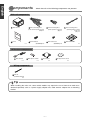
English
DVD Navigation System with 6.5" Wide TFT Display and DVD Multi-Source Receiver
MODEL
INSTALLATION MANUAL
Installation
2
3
5
Names and functions of terminals
Connecting the vehicle speed pulse, parking brake, and reverse wires
System connection example
6
10
12
Installing the GPS antenna
Installing the main unit
13
16
Nederlands
Connections
Components
For your safety in using the AVN51D
Installation Diagram
Italiano
Before
installation
Français
Contents
Español
Be sure to read this installation manual thoroughly prior to installation and making connections. If
installation methods or non-standard parts not specified in this installation manual are used, accidents
or injury may result.
Professional installation is recommended, contact the place of purchase to schedule an appointment.
After reading the owner's manual and the installation manual thoroughly, keep them in a safe place for
later reference.
To dealers:
Give this installation manual to the customer after installation and all connections have been
completed.
Svenska
English
Components
Check that all of the following components are present
Main unit components
English
1 Main unit x 1
2 Interconnecting wires
3 Interconnecting wires
(Power and front speaker connector)
(10P) x 1
Español
6 Hex-head bolt
5 Panel
(Rear speaker connector)
(6P) x 1
7 Flat head screw
(Red:M5x8) x 8
x1
4 Interconnecting wires
(Steering remote control
connector)
(8P) x 1
8 MAP DVD-ROM
x1
(Red:M5x8) x 8
GPS antenna components
Français
9 GPS antenna
10 Waterproof cushion
11 Ground plate
12 Body protective sheet
x1
x1
x1
x1
Wiring components
Italiano
13 Wire tie
(for GPS antenna)
x4
Tip
Nederlands
When installing the main unit, some vehicle models may require the use of items that need to be
obtained separately such as a power supply adaptor wire, radio antenna adaptor wire or mounting
bracket.
Svenska
-2-
Warnings and caution signs, illustrated bellow, are posted throughout this manual as well as on the AVN51D.
They show safe and correct ways to handle the main unit to prevent personal injury to you and others and
avoid damage to property.
Before reading through the manual, take time to read through and learn the important information listed in
this section.
English
For y our safety in using the AVN51D
This "Warning" sign indicates a situation in which incorrect handling may
result in death or serious personal injury.
This "Caution" sign indicates a situation in which incorrect handling may
result in personal injury or may result solely in damage to property.
This section contains information that can help to prevent problems and
damage to the main unit, and also contain other useful information.
• Never supply power to another electrical appliance
by splicing or tapping into this main unit's power wire.
Otherwise, the current capacity of the wire will be
exceeded, resulting in a fire or electric shock.
• Do not install this main unit in locations where it may
interfere with the operation of the steering wheel,
shift lever, brake pedal, etc. Otherwise, an accident
or injury may result.
• Never attempt to disassemble or modify the main
unit. Otherwise, an accident, fire, or electric shock
may result.
• When making holes (example: drilling) be sure to
wear protective eyewear. Otherwise, an injury such
as loss of eyesight may result.
• Exposed wires must be insulated with electrical tape.
Otherwise, a short circuit, fire, or electric shock may
result.
• To prevent a short circuit from occurring, disconnect
the battery's negative terminal before installing this
main unit. Otherwise, an electric shock or injury may
result.
• Bundle wires and harnesses with electrical tape or
wire ties to prevent them from interfering with moving
parts. If they should entangle with the steering wheel,
shift lever, or brake pedal, an accident may result.
• This main unit is intended for operation in DC 12volt,
negative-grounded vehicles only. Never use it in 24volt vehicles such as heavy trucks or diesel vehicle
with cold-region specifications.
-3-
Svenska
• When using an existing nut and/or bolt from the
vehicle to ground this main unit, do not use any that
secure parts of the steering or braking systems.
Otherwise, an accident may result.
• Do not modify this system for use other than that
specified herein. Also, do not deviate from the
installation procedures described herein; Eclipse will
not be held liable for damages including, but not
limited to serious injury, death, or property damage
resulting from installations that enable unintended
operation.
Nederlands
• When installing this main unit, never use the existing
nuts or bolts that secure parts of the fuel tank, or the
steering, or braking systems. Otherwise, improper
steering, or braking or a fire may result.
Italiano
• When installing the main unit into a vehicle with a
passenger side air bag, do not secure it to the air
bag's cover or in places where it may impede air bag
deployment. Otherwise, proper air bag operation may
not be ensured in the event of an accident, causing
injury or death.
• To prevent damage to the vehicle, confirm the
locations of hoses, electrical wiring, and the fuel tank
prior to drilling holes to install this main unit. Also,
take precautions so that the main unit does not
interfere, nor come in contact with them. Otherwise,
a fire may result.
Français
• Do not install this main unit in locations where it may
obstruct the driver's view, or where it may endanger
passengers in the vehicle. Otherwise, an accident or
injury may result.
Español
Tip
English
• Do not place the vinyl storage bag over a person's
head. It may cause a serious accident or death by
suffocation.
• Do not operate the main unit in a malfunctioning
condition, for instance, when the audio does not play.
Doing so may result in an accident, fire, or electrical
shock.
• Do not disassemble or rebuild this main unit. Doing
so may cause an accident, fire, or electrical shock.
English
• If an abnormal situation occurs, such as foreign
matter entering or liquid splashing on the main unit,
or smoke or a strange odor emitting from the main
unit, shut off the main unit immediately and consult
the dealer from whom you purchased it. Continued
operation may cause an accident, fire, or electrical
• When it is necessary to replace the fuse, always use
a fuse of the correct rating (number of amperes). Use
of fuses with higher amperage ratings may cause a
fire.
Español
• This main unit must be operated only as on-board
main unit, or it may cause electrical shock or injury.
• For best results, this main unit should be installed by
a professional installer.
Contact the dealer whom you purchased the main
unit for an appointment.
• Do not play distorted sounds for long periods of time;
the speakers may overheat and cause a fire.
Français
• When installing this main unit, be sure to use the
supplied mounting hardware. If parts other than
those supplied are used, the main unit may be
damaged internally, or may not be held in place
securely and become dislodged.
• Once installation and wiring have been completed,
return the brakes and electrical equipment such as
lights, horn, hazard warning lights and turn signal
lights to their original places, and check that they
operate correctly. If you use the vehicle while any of
this equipment is not working correctly, fire, electric
shocks or accidents may occur.
• Avoid installing this main unit in places where it may
get wet, such as near windows, or in places that are
moist or dusty. Presence of liquid, moisture, or dust
inside this main unit can cause short circuiting
resulting in smoke or fire.
Italiano
• Use supplied wire harness with this main unit. Other
manufacturers may use a similar wire harness
connector but pin configurations are incorrect for use
with Eclipse main units and can damage the main
unit. Prior to powering up the main unit, please make
sure the main unit is properly grounded with the
vehicle chassis. If no ground is available to the
chassis, add a ground strap from the main unit to the
vehicle chassis to improve the ground.
• If this main unit is not connected properly, a short
circuit, fire, or accident may occur.
• When routing wires, use precautions to prevent
contact of sharp metal parts such as brackets or
screw tips. Otherwise, a short circuit, electric shock,
fire, or accident may result.
Nederlands
• Do not use with speakers having 1 to 3 ohms
impedance. This main unit is designed to be used
with high-powered speakers rated above 50w with
impedance rating between 4 and 8 ohms.
• Play the audio at a moderate volume level that
permits you to hear sounds from outside the vehicle.
Driving without being able to hear outside sounds
may result in an accident.
Svenska
-4-
9 GPS antenna
(When installing inside the vehicle)
English
Installation Diag r am
Tip
9 GPS antenna
(When installing outside the vehicle)
Italiano
• If installing the GPS antenna inside the vehicle, the location and the slope of the vehicle's windshield
will determine the accuracy of the GPS antenna to receive the GPS signal. If the GPS antenna
location inside the vehicle is hindering the accuracy of the GPS antenna, then you may want to install
the antenna outside of the vehicle.
• The materials used in front and rear vehicle windows can cause GPS reception sensitivity to drop
significantly. If this happens, install the GPS antenna on the outside of the vehicle.
Français
Tip
Español
1 Main unit
Nederlands
Svenska
-5-
English
Name and functions of ter minals
• Never cut the insulation on the power wire or use it to power any other equipment. If the rated current capacity of the power wire
is exceeded, fire and electric shocks may result.
• The wires should be secured with tape or a similar securing method to prevent any obstructions while driving. If they get wound
English
or entangled around components such as the steering wheel, shifting lever, or brake pedal, accidents may result.
• If removing the end of the wire to connect to another wire, be sure to wrap PVC tape or a similar wire insulating method around
the connection to insulate it. If the connection is not insulated, fire or accidents may result.
• Use supplied wire harness with this main unit. Other manufacturers may use a similar wire harness connector but pin
Español
configurations are incorrect for use with Eclipse main units and can damage the main unit. Prior to powering up the main unit,
please make sure the main unit is properly grounded with the vehicle chassis. If no ground is available to the chassis, add a
ground strap from the main unit to the vehicle chassis to improve the ground.
• Do not use with speakers having 1 to 3 ohms impedance. This main unit is designed to be used with high-powered speakers
rated above 50w with impedance rating between 4 and 8 ohms.
9
GPS ANTENNA
D
Français
1
MAIN UNIT
1P
8P
ANTENNA PLUG
4
INTERCONNECTING WIRES
Italiano
※ If installing video main unit such
as a VTR, replace the wire with
the one that is sold separately.
10
11
C
12
20P
10P
13
B
1
A
Nederlands
2
13P
3
4
6P
5
6
9
7
2
INTERCONNECTING WIRES
(Power and front speaker
connector)
8
3
Svenska
INTERCONNECTING WIRES
(Rear speaker connector)
Tip
• Refer to page 7 for details on the wire colors and connection points for Interconnecting wires
3 and 4 .
• Refer to page 8 for details on connection points
A
and terminals.
-6-
,
B
, and
D
2
, and
for the main unit wires
Caution
1
2
and
3
and
4
Never connect the power supply to the speaker wires (No.6 and No.7),
otherwise it will cause damage to the main unit.
English
Wire colors and connection points for connection wires
B+ (Yellow)
Connect where power is constantly available, regardless of the ignition key's position.
2
ACC (Red)
Connect where the power comes on when the ignition is in the ACC position.
3
Illumination power supply (Orange/White)
Connect to where power comes on when the vehicle light switch is turned on.
4
Antenna power supply (Blue)
5
Español
Connect to the automatic-antenna control terminal of the vehicle.
Control power supply (Blue/White)
Connect the control terminal for the external amplifier, etc.
6
Front speaker output wires
Connect to the front speakers.
Left +
Right +
White/black:
Gray/Black:
Left Right -
Green/black:
Purple/Black:
Left Right -
Rear speaker output wires
Connect to the rear speakers.
8
No connection (Pink)
9
Ground (Black)
Green: Left +
Purple: Right +
C
Genuine steering remote control terminal
Connect to the vehicle steering remote control.
※ Compatible vehicle models for installation : Vehicles with voltage detection-type steering remote control.
Ask your dealer for details.
Italiano
Connect where good body grounding is available.
Français
7
White:
Gray:
Nederlands
Svenska
-7-
English
Main unit connections
10 ACC
ON/OFF power supply terminal (blue/white)
If you use this terminal to connect main unit such as an external amplifier, you can still hear the audio guidance
from the navigation system even when audio is turned off. Connect it to the control terminal for the external
amplifier or other main unit.
※ A popping noise may be heard when the engine is being started or the ignition switch is at the ON position, but
this is normal and is not the sign of a malfunction.
English
11 Vehicle
speed pulse signal wire (Purple/White)
Connect to the vehicle speed pulse signal terminal.
12 Parking
brake signal wire (Red/White)
Connect to the parking brake signal terminal.
13 Reverse
signal wire (Green)
Español
Connect the reverse signal output of the vehicle to this terminal.
A
E-LAN terminal (13P)
Connect to the E-LAN terminal of the CD changer, etc.
B
VTR output terminal (Yellow)
Connect to the monitor with video input.
Français
D
Back-eye camera external input terminal (4P)
Used with the Eclipse back-eye camera (sold separately).
Italiano
Nederlands
Svenska
-8-
Tip
• You will need to purchase the necessary vehicle component adapter wire for the vehicle so that the
power supplies can be utilized. (Contact the dealer for further details.)
English
- Vehicle connections -
• Be sure to wrap the connection wires with electrical tape or another insulation method to insulate them.
- Example of using vehicle adapter wires -
Vehicle harness
Español
Power supplies
for combined
equipment
From main unit
Français
Vehicle component adapter wires
Italiano
Nederlands
Svenska
-9-
English
Connecting the vehicle speed pulse , par king
br ak e , and reverse wires
Notes on installation
English
• Check the vehicle speed pulse signal, parking brake signal, and reverse signal carefully before making
the connections. If the wires are incorrectly connected, accidents or problems with correct operation
may result.
• The label on the vehicle speed pulse signal wire contains a protection circuit, so do not cut the wire or
remove the protective circuit, otherwise problems with operation may result.
• Bind the wires together with tape so that they do not cause an obstruction while driving. If they become
Español
wound or entageled around parts such as the steering wheel, shifting lever, or brake pedal, accidents
may result.
Tip
The locations where the vehicle speed pulse signal wire, parking brake signal wire, and reverse wire may
vary depending on the vehicle model and grade. Ask the car dealer or your nearest Eclipse dealer for
details.
Français
- A connecting point for the vehicle speed pulse signal (example) -
Tip
Italiano
Always be sure to connect the vehicle speed
pulse, otherwise the measurement precision will
be greatly reduced.
Vehicle speed pulse
signal wire (vehicle harness)
Nederlands
Vehicle speed pulse
signal wire
(purple/white) of
connection wire
Engine computer
Splicing connector
(sold separately)
Contains a protective circuit
so never remove.
Svenska
- 10 -
English
- A connecting the point for parking brake (example) Hand-operated
Parking brake
Attach a splicing
connector at this location.
Parking brake
Signal Wire
Parking brake
signal wire
Foot-operated
Parking brake
Tip
• Be sure to connect the reverse signal wire. If it is
not connected, the vehicle position may be
incorrect when the vehicle is reversed.
Attach a splicing
connector at this location.
Reverse lamp
Español
- A connecting point for the reverse signal (example) -
Français
• Use a circuit tester to confirm that a sensing
voltage of 6 V or higher is generated when the
vehicle is reversed.
Reverse signal wire
Italiano
Reverse signal wire
Nederlands
Svenska
- 11 -
English
System connection example
English
• Never cut the insulation on the power wire or use it to power any other main unit. If the rated current
capacity of the power wire is exceeded, fire and electric shocks may result.
• The wires should be secured with tape or a similar securing method to prevent any obstructions while
driving. If they get wound or entangled around components such as the steering wheel, shifting lever,
or brake pedal, accidents may result.
•If removing the end of the wire to connect to another wire, be sure to wrap PVC tape or a similar wire
insulating method around the connection to insulate it. If the connection is not insulated, fire or
accidents may result.
Tip
Español
• Install and connect all of the peripheral units before connecting them to the main unit.
• Do not remove any of the protective caps (RCA, etc.) unless in use.
• Be sure to wrap the connection wires with tape (PVC tape) to insulate them.
BEC105 (sold separately)
9
4P
GPS ANTENNA
8P
Français
1
MAIN UNIT
4
INTERCONNECTING WIRES
(Steering remote control connector)
1P
TO STEERING REMOTE CONTROL
20P
Italiano
Nederlands
ANTENNA PLUG
L
NA
I
RM
TE
)
AL
11
N
G
N
I
ge
pa
ES
TIO
o
S
C
t
L
E
fer
PU
NN
Re
ED
CO
L(
PE
A
1)
S
N
NO
E 0)
e1
SIG
ICL ge 1
ag
p
H
E
to
VE pa
AK
e
fer
TO fer to
BR
hit
Re
(Re
e/W
L(
ING
u
A
K
l
N
R
B
hite
PA
SIG
/W
TO
SE
rple
or)
R
u
10P
e
E
P
nit
hit
EV
mo
W
l
R
/
a
d
n
TO
Re
ter
llow
n
ex
Ye
ree
ing
d
G
s
e
u
R
en
2V
wh
hite
+1
)
e/W
RY pply
ers
g
v
E
n
o
Su
TT
ly)
Ora
ec
e
pp
BA ent
ov
Blu
Su
TO rman
rem
e
er
)
t
(
)
i
w
e
+
h
3 INTERCONNECTING WIRES
(P
n(
Po
OR
e/W
C(
atio
NIT
(Rear speaker connector)
Blu
AC
ly)
min
MO
pp
Illu
TO
u
(
O
S
T
H
ly)
Y(
p
TC
A
I
p
L
SW
(Su
RE
HT
NT
NA
13P
LIG
EN
ME
6P
ck
T
P
D
I
A
Bla
AN
QU
HE
R
E
E
W
TO
CH
PO
EA
TO
OF
E
FRONT
IR
TO GROUND
NW
SPEAKERS
-O
N
k
R
Pin
TU
2 INTERCONNECTING WIRES
TO
N
IO
(Power and front speaker connector)
CT
NE
REAR SPEAKERS
ON
C
NO
Svenska
POWER CONNECTOR WIRE
(Supplied with CD changer)
TO BATTERY+12V
(Permanent Supply)
CH3083
(sold separately)
13P
2P
llow
Ye
DIN WIRE
k
c
Bla
(Supplied with CD changer)
TO GROUND
- 12 -
Notes on installation
English
Installing the GPS antenna
• The wires should be bound together with tape or a similar securing method (example: wire ties) so that
they do not interfere with driving. If it becomes wound or entangled around parts such as the steering
wheel, shifting lever, or brake pedal, accidents may result.
• Do not install the GPS antenna where it will obstruct the driver's vision or where it will be an obstacle
while driving, otherwise traffic accidents may result.
• If the vehicle glass is a special type of glass such as
heat-reflective glass or bullet-proof glass, be sure to
install the GPS antenna outside of the vehicle. If the
GPS antenna is installed inside of the vehicle, the
reception sensitivity will severely drop and will affect
the accuracy of the position measurement.
• If installing the GPS antenna inside the vehicle, the
location and the slope of the vehicle's windshield will
determine the accuracy of the GPS antenna to
receive the GPS signal. If the GPS antenna location
inside the vehicle is hindering the accuracy of the
GPS antenna, then you may want to install the
antenna outside of the vehicle.
• Hold the main antenna unit when removing the
antenna. Do not pull on the wire, otherwise it may
become damaged and result in problems with correct
operation.
• If installing the GPS antenna outside the vehicle,
remove the main antenna unit when washing the
vehicle. (If you wash the vehicle with the main
antenna unit still attached, avoid spraying the wire
section directly with water so that no water gets
inside the vehicle.)
• The magnet that is attached to the GPS antenna is
extremely strong. Be sure to note the following when
installing the antenna.
• Wipe the installation surface thoroughly so that it is
clear of any dirt, moisture, or grease before installing
the antenna.
• Route the GPS antenna wire as far away as possible
from TV and radio antennas, and wires, otherwise, it
may cause interference with video and audio signals.
- 13 -
• Keep tway from watches and he antenna
amagnetic cards, otherwise they may be
damaged and/or rendered unusable.
Svenska
• Do not apply any coatings to the GPS antenna,
otherwise it may cause a drop in the reception
sensitivity of the antenna.
• Do not put the antenna down on the ground or on
dirty or dusty surfaces. If iron filings become
attached to the magnet, they may cause damage
to the vehicle's body.
Nederlands
• If the attachment surface is a non-plastic surface
such as genuine leather, wood panel, or cloth,
attaching the antenna may damage the surface
finish. Do not attach the ground plate to such
surfaces.
• If installing the GPS antenna outside the vehicle,
remove the main antenna unit if leaving the vehicle
unattended for long periods in order to prevent theft
or malicious damage to the antenna.
Italiano
• The materials used in front and rear vehicle windows
can cause GPS reception sensitivity to drop
significantly. If this happens, install the GPS antenna
on the outside of the vehicle.
• The GPS antenna should be installed in a level
position where the signals will be as unobstructed as
much as possible, such as on the vehicle's roof.
Satellite signals cannot be received if the antenna is
obscured or obstructed.
Français
• If installing the GPS antenna inside the vehicle, be
sure it is mounted to the ground plate.
• Do not install the antenna in places (such as front
pillars and roof panel) that are shielded from the sky.
Español
Tip
English
- Installation inside the vehicle (example) 1
Choose an installation location on the dashboard
which is flat and has a clear view of the sky.
Tip
11 Ground plate
9 GPS antenna
English
• Select a location that is at least 20 in. away from
the main unit. If this is not done, the GPS
measurement precision will drop.
• Be sure to use the ground plate when installing
the GPS antenna. If the ground plate is not used,
the reception sensitivity will drop and will affect
the accuracy of the position measurement.
2
Install the ground plate to the dashboard.
3
Install the GPS antenna to the ground plate.
Español
Tip
Front of vehicle
Tip
Français
If installing the GPS antenna inside the vehicle, the installation location and the shape of the vehicle's
body will determine GPS accuracy. Accuracy is usually lower when the GPS antenna is installed
inside the vehicle.
4
Secure the GPS antenna wire .
5
Route the GPS antenna wire along the crevice
between the front windshield and the dashboard.
Tip
Tape
Italiano
Tip
9 GPS antenna
If the GPS antenna wire protrudes from the
dashboard, wind tape around it so that it stays
securely fixed in the crevice between the front
windshield and the dashboard.
6
9 GPS antenna wire
Nederlands
Route the GPS antenna to the main unit's
installation location.
Front of vehicle
Tape
Svenska
- 14 -
1
Choose an installation location where the GPS
antenna can be attached securely.
2
Remove the backing paper from the body
protective sheet and attach the sheet to the
vehicle.
3
9 GPS antenna
English
- Installation outside the vehicle (example) -
12 Body protective
sheet (clear)
Install the GPS antenna on top of the body
protective sheet.
Front of vehicle
5
Route the GPS antenna wire inside the vehicle's
trunk and secure it with tape.
Tape
10 Waterproof cushion
Attach the waterproof cushion so that the GPS
antenna wire is flat against the weatherstrip when
the trunk lid is closed.
To aid in sliding the waterproof cushion in finding
the desired mounting location, apply plain or
soapy water to the waterproof cushion.
Route the GPS antenna wire while securing it
with wire ties.
7
Route the GPS antenna wire to the main unit
while securing it with tape.
13 Wire tie
Weatherstrip
Italiano
6
Front of vehicle
Français
Tip
Español
4
Front of vehicle
Route to
main unit
Nederlands
Tape
Svenska
- 15 -
English
Installing the main unit
- Installation angle -
Tip
English
To maintain proper function, the main unit must be
mounted less than 30 degrees. If the angle is in
excess of 30 degrees, DVD/CD skipping and
improper DVD/CD ejection may occur.
Front
30˚ or less
Level (reference)
Español
- Mounting the main unit -
Tip
Center cluster panel
Français
• Carefully bind any excess length of wire that
is connected to the main unit and secure it
to an area of empty space in the vehicle so
that it does not dislodge or interfere with the
main unit or vehicle-side equipment. If the
wires are not handled correctly, operating
problems or short-circuits may occur, and
this may result in the danger of fire or other
accidents.
• Connect all wires before installing the main
unit.
Italiano
1
Remove the pocket and any other accessories
from the center cluster to make room for the main
unit.
2
Remove the mounting brackets for the pocket.
3
Attach the brackets to the main unit.
Pocket, etc
Mounting bolts
1
Main unit
Tip
Nederlands
Be sure to use the supplied accessory mounting
screws (Red: M5 x 8) as the mounting screws. If
any other screws are used, they may damage the
inside of the main unit.
4
Install the main unit in the vehicle.
6 Hex-head bolt
(Red:M5 x 8) x 8
Tip
Svenska
Be careful not to forcefully push on the main unit's
display or buttons during installation. This may
result in damage to the main unit.
Mounting bracket
Hex-head bolt
6 (Red:M5 x 8) x 8
Flathead
7 screw
(Red:M5x8) x 8
Select the screws in accordance with the shapes
of the screw holes in the mounting bracket.
- 16 -