1
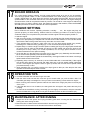
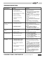
1/5 SCALE DUCATI 999R NITRO POWERED R/C MOTORBIKE
Official Product under license of Ducati Motor Holding S.p.A.
NO.6301-F
Please ensure you read and fully understand all the instructions before operation.
The contents are subject to change without prior notice due to product improvements and specification changes.
INSTRUCTION MANUAL
WARRANTY
Thunder Tiger Corporation guarantees this model kit to be free from defects in both material and workmanship.
The total monetary value under warranty will in no case exceed the cost of the original kit purchased. This warranty
does not cover any components damaged by use or modification. Part or parts missing from this kit must be
reported within 60 days of purchase. No part or parts will be sent under warranty without proof of purchase. To
receive part or parts under warranty, the service center must receive a proof of purchase and/or the defective part
or parts. Should you find a defective or missing part, contact the authorized Thunder Tiger Service/Distributor
nearest you. Under no circumstances can a dealer or distributor accept return of a kit if assembly has started.
CAUTION
Thank you for purchasing a Thunder Tiger Product.
Please read all instructions and familiarize yourself with the products and controls before operation.
1. This product is not a toy. It is a high performance model product. It is important to familiarize yourself
with the model, its manual, and its construction before assembly or operation. A child operating under
the supervision of the adults is necessary.
2. Always keep this instruction manual ready at your hand for your assembling and operating reference,
even after completing the assembly.
3. Make sure all the screws are properly tightened and all the parts are checked after running the car for a
long period of time.
4. For the best performance, it is important to make sure all the moveable parts work free without binding.
5. Do not operate model products in rain, on public roads, near crowds, near airport, or near areas with
restricted radio operation.
6. Always keep fuel away from heat and open flame. Only operate in open, well-ventilated area. Store fuel
in cool, dry area. Keep the fuel bottle cap tightly closed. Clean up any leak or excess fuel before starting
the engine.
7. This product, its parts, and its construction tools can be harmful to your health. Always exercise extreme
caution when assembling and/or operating this product. Do not touch any part of the model that rotates.
8. Check your radio frequency with the proper operating frequency of the area or country. Always check to
see if there are any modelers operating on the same frequency as yours. Also, check your radio for
proper operation before operating a model.
ITEMS INCLUDED
Side-guards
Motorbike chassis (w/
DUCATI999R body,
rider & PRO-12BK
engine Pre-Installed)
2 high torque
servos.
2ch Transmitter
Pistol Grip or Dual Stick
For Choice
Quick fill
fuel bottle
TOOLS INCLUDED
1.5mm, 2mm, 2.5mm, 3mm
Hex wrench set
Glow plug wrench
5-5.5mm wrench
7-10mm wrench
Double sided tape
Hex - Starter shaft
ITEMS REQUIRED FOR OPERATION
Power drill or a
hand held starter.
Philips screwdriver
0.5mm/1/8"Flathead screwdriver.
Air filter oil
Glow plug starter and charger
Fuel
RECOMMENDED ITEMS
These items are not required for your operation but are a good idea for safety.
● Protective gloves ● Safety glasses ● Thread Lock / Screw Cement
1
RX battery pack and
battery charger
IMPORTANT NOTES AND WARNING
FUEL SELECTION
1. Choose a fuel from a reputable, brand name company that is approved for car/truck use. Do not
use airplane or boat fuels in your car/truck. Choose methanol based model engine glow fuel that
has a nitro content in the range 10%-30% and 5% to 18% caster/synthetic oil content for
lubrication. Lower nitro percentages will generally result in a cooler engine running temperature
and therefore last longer before needing a rebuild; cooler-running engines also generally
produce less power. 20% nitro is the most widely used fuel.
2. Fuel color is for identification purpose only and is not important to performance or durability of
your engine.
3. Be careful. If the tank overflows it might get on your radio gear or on your brakes and it may
create an unsafe driving situation. Always keep your fuel bottle closed when not in use.
4. Do not dispose of fuel or empty fuel containers in a fire. It may possibly cause fire or explosion.
ENGINE
1. For proper engine break-in procedure, please refer to the manual of your engine.
2. Never run your vehicle without the air filter .If the vehicle will be operated in an area with fine
dust, use filter oil or caster oil instead of fuel. It is important that the foam is only moist to trap dirt
and allow air passage. With the foam too wet, limited air can pass through; therefore, limiting
engine performance.
3. The parts around engine could be dangerously hot after operation. Do not touch it without any
protection!
RADIO OPERATION
1. When turning radio on, first turn on the transmitter and extend the transmitter antenna.
2. Then, turn on the receiver. When turning off, first turn the receiver off, then the transmitter off.
FIRST AID
1. If you drink nitro fuel by accident, immediately drink large quantities of water and try to induce
vomiting. Consult with physician right after then.
2. If the nitro fuel gets into your eyes, rinse them well with water. Consult with physician right after
then.
3. If the fuel gets onto your skin, wash it well with soap and water.
WARNING
1. Improper operations may cause personal and/or property damage. Thunder Tiger and its
distributor have no control over damage resulting from shipping, improper construction, or
improper usage.
2. Thunder Tiger assumes and accepts no responsibility for personal and/or property damages
resulting from the use of improper building materials, equipment and operations. By the act of
assembling or operating this product, the user accepts all resulting liability. If the buyer is not
prepared to accept this liability, then he/she should return this kit in new, unassembled, and
unused condition to the place of purchase.
2
1
INSTALLING THE RADIO GEAR
Skip if already assembled in RTR version
a
b
c
d
e
f
g
h
a. Install the receiver switch onto the servo mount beside the steering servo with 2 tap screws.
b. Install the steering servo onto the servo mount with four tap screws. (Note the output shaft
should be centered between the chassis frames.)
c. Install the throttle servo onto the servo mount with 4 tap screws. The mounting position is shown
in this manual.
d. Install the receiver above the space between two frame posts using supplied double-sided tape.
e. Install the receiver battery pack on the bottom of the chassis. Then secure the battery pack with
large zip tie.
f. Ensure all wires are securely connected to the receiver:
steering servo connector plug - into the channel 1 slot
throttle servo connector plug - into the channel 2 slot
battery switch connector plug - into battery slot.
Then thread the receiver antenna/wire through the antenna mount.
g. Thread the receiver antenna/wire all the way through the antenna tube and install the antenna
tube onto the mount. Place the supplies antenna tip over the top of the antenna tube to secure
the antenna/wire.
h. Then, use a small cable-tie or zip tie to organize the excess wiring from any high temperature or
moving parts.
3
2
INSTALLING STEERING SERVO LINKAGE
Skip if already assembled in RTR version
a
c
b
109 mm
13 mm
a. Build the oil-filled steering damper & servo linkage as shown on the diagram. The initial factory
setting of the steering servo linkage (with damper) is 109mm without pressing or extending
between each two ends. Any time the damper is removed or dissembled, this distance should be
checked to ensure proper operation of the steering damper. Measure the length of the outer
spring within 13mm from the adjustable collar to the bottom of the damper when finished.
b. Pop the cap of the damper onto the standoff ball on the steering servo horn.
c. Pop the tie-end onto the standoff ball on to the steering mount to complete the steering system.
Low Speed Handling Setting
If the bike will not run straight at low speed, reset the length of the steering turnbuckle to 109mm or
re-fill the oil inside the damper with lower grade oil (Initial set up of oil: #400)
High Speed Handling Setting
If you find the front wheel is getting vibration or unstable at high speed, re-fill the damper oil with
higher grade oil (Initial set up: #400), this will improve the high speed handling, but may effect the
low speed cornering or stability.
Optional Steering Servo Linkage
a. The original damper has to be removed from the motorbike.
b. Build the steering damper as shown in the diagram.
c. Fill the aluminum damper with silicon shock oil (Suggested silicon oil : #400) up to the top of the
damper body.
d. Slowly move the piston up and down to release the air bubbles. Let the damper sit for a while to
allow any remaining air bubbles to surface.
e. Slowly thread the upper cap with shock bladder onto the damper body. And then tread the
aluminum shaft adjust mount into the plastic tie-end
f. With the servo at neutral, loosen the aluminum shaft adjust mount with a 1.5mm hex wrench.
Insert the damper shaft into the adjust mount. Then, manually move the shaft to keep length of
the whole damper with tie end within the 109mm length with the spring slightly compressed
when finished. Set the screw tight on the aluminum shaft adjust mount.
g. Repeat 2a, 2b, and 2c.
4
3
INSTALLING THROTTLE/BRAKE LINKAGE
Skip if already assembled in RTR version
b
a
d
c
a. Build the throttle/brake linkages as shown in the diagram.
b. Install the kinked linkage end onto the carburetor lever, and secure the disc brake wire onto the
pivoting linkage collar with 1.5mm set screw.
c. Install the throttle servo horn onto throttle servo output shaft.
d. Secure the disc brake wire onto the brake lever on the rear disc brake with a 1.5mm set screw.
Optional Front Disc Brake (Purchase separately)
a
Apply CA Glue
on the outer brake pad
Apply CA Glue
on the inner brake pad
b
c
a. Build the front disc brake as shown in the diagram. Use a 3 mm hex wrench to detach the right
front plastic disc brake off the front forks.
b. Mount the disc brake and brake pad where the plastic disc brake is mounted. Sandwich the brake
disc between the brake pads. Secure the disc brake wire onto the pivoting linkage collar with
1.5mm set screw.
c. Route the disc brake wire through the supplied steel spring tubing and the vented window section
on the chassis frame. Secure the disc brake wire onto the brake lever and a linkage collar on the
front disc brake with a 1.5mm set screw.
5
4
INSTALLING THE SIDE GUARD WIRE AND
ADJUSTING THE STABILITY
a
c
b
a. Use a hex driver to loosen the screws of the mount on the side of the body frames.
b. Install the supplied side guard wire into the mounts and re tighten the screws..
c. If you are unable to run the motorbike straight l, it may caused by improper set-up of the steering
servo linkage or the rear wheel may not be parallel to the front. To re-adjust the steering servo
linkage, repeat step 2a . To get the rear wheel parallel and achieve correct tension of the rear
drive chain, detach the 2.5mm screw on the rear end of the swing arm. Use you finger tip to feel
the best set-up of the tension of drive chain. The ideal set-up is around 2 mm range of
movement up and down. (Note: The rear tire and the swing arm must be parallel, if not, loosen
the 2.5mm screw on the right side of swing arm to parallel the rear wheel with the rear swing
arm.)
Detach the 2.5mm screw on the
rear end of the swing arm
Leave 2mm range of movement
up and down
Not Parallel
Parallel
Loosen the 2.5mm screw on the
right side of swing arm
After adjusting, tighten the
screw again.
6
5
CHARGING THE GLOW PLUG STARTER
a
c
b
a. Plug the charger into an AC outlet, and then pull on the igniter lever to accept the charging
adapter.
b. At this point, the small red LED indicator on the charger should light up indicating the charging
sequence is in progress.
c. When the charging complete, pull on the glow plug igniter lever to unplug the glow igniter.
Charge the new glow plug igniter for 16 to 24 hours on the first charge. For subsequent
charges, charge it about 12 hours before next use.
NOTE:
If the igniter gets warm or hot during the charge, unplug the igniter from charger immediately. A
warm / hot igniter means the igniter is overcharged. Overcharging can damage the internal battery
in the igniter; thus, shortening its life.
6
PREPARING THE RADIO
a
c
b
a. Install the antenna into your transmitter.
b. Check the frequency printed on the transmitter crystal.
c. Check the frequency printed on the receiver crystal, and make sure it matches with the
transmitter crystal. Make sure no one is operating on the same frequency as you when switching
your model on and during use. When there is a radio glitch, it will most likely be caused by
improper crystals installed, damaged crystal, or people operating on the same frequency
causing interference.
7
RADIO BATTEY INSTALLATION
a
a. Install 8 AA-size alkaline
batteries into transmitter.
Ensure polarities are correct
as per the '+' & '-' markings
inside the battery
compartment.
b. Re-secure the RX battery
pack back onto the battery
bracket with the large zip-tie.
b
7
8
CHARGING THE RECEIVER BATTERIES
9
RADIO OPERATION
The RX battery pack and charger must be purchased seperately
The RX battery pack must be fully charged before running the
motorbike.
For best results, let the RX battery pack cool before charging.
Heat may prevent the batteries from charging to full capacity and
also decreases the performance of the batteries.
Once the batteries are ready to be charged, first plug the A/C
charger into the outlet of AC power source, then plug your RX
battery pack in the charger.(The charging time is about 10-hours.
For fast charging, you may purchase one peak detection fast
charger in the hobby shop for your convenient use.)
Continue to monitor the battery as it is being charged. As soon as
the battery is fully charged, disconnect the charging jack from the battery.
Warring: NiMh battery pack must be recycled or disposed of properly. Do not short circuit the RX
batter pack. This may cause burns and damages to your battery pack. Never leave charging
batteries unattended.
a
c
b
a. When using your model, always ensure the transmitter is switched on first.
b. Then, turn on the receiver. When turning off, first turn the receiver off, then the transmitter.
c. To reverse the functions of servos, use the small, white servo reverse switches located on top of
the pistol transmitter (or the inset servo reverse switches located at the center of the stick
transmitter). To trim the servos on pistol transmitter, use the large, trim levers on top and side of
the steering wheel (the top trims steering, and the side trims throttle/brake). On a stick
transmitter, the trim levers are located accordingly around the sticks
10
OPERATING RADIO - STEERING FUNCTION
a
c
b
Due to its unique steering system, the following advises for the controlling should be noted,
a. First, flip the steering servo reverse switch (see 9c). The steering is basically accomplished by
changing the center of body gravity, not the turning of the forks. With the radio transmitter and
receiver on, turn the steering wheel/stick to the right. The body leans towards the right side (The
front tire/wheel should turn left ), the chassis follows, leaning to the same side. If not, flip the
steering servo reverse switch again
b. Return the steering wheel/stick to neutral. The front tire/wheel should point straight forward. If
not, use the steering trim lever to correct it.
c. Turn the steering wheel/ stick to the left. The front tire/wheel should turn right.
8
11
OPERATING RADIO - THROTTLE/BRAKE FUNCTION
a
b
about 1mm
c
about 1mm
a. Check the radio throttle/brake functions. With the radio transmitter and receiver on, pull the
trigger/push the stick forward. The carburetor should be fully opened and the brake disengaged.
To check the brake is not engaged, simply spin the wheel whilst pulling the trigger/pushing the
stick forward. To reverse this function, flip the throttle/brake servo reverse switch.
b. Return the trigger/stick to neutral. The carburetor should be closed to a point where the idle has
been set (see step for ADJUSTING THROTTLE/BRAKE LINKAGE), and the brake still
disengaged. If not, use the throttle/brake trim lever to correct it.
c. Push the trigger/pull the stick backward. The carburetor opening should still be the same at
neutral, throttle spring compressed slightly, and the brake engaged.
9
12
ADJUSTING THROTTLE/BRAKE LINKAGE
a
b
d
c
d
e
The DUCATI 999R GP motorbike is equipped with a rear disc brake that bolts on between the rear
wheel and the rear swing arm. The rear brake system is preset at the factory. As the brake material
wears, you may need to replace the brake pad (see spares list) and future adjustments may be
necessary.
a. To set the throttle/brake linkage, first the radio should be on and set to neutral; thus, the servo is
at neutral position.
b. With the servo at neutral, adjust the tension of the brake wire to a point where the brake lever
almost engages the brake system.
c. With the servo at neutral, loosen the throttle lever collars with a 1.5mm hex wrench. Then,
manually close the carburetor, and set the collar (next to the spring) with the spring slightly
compressed. Then, set the other collar next to the linkage pivot.
Replacing the rear brake pads
d. If the brake pads are worn or damaged and need replacing, loosen the two bolts on the rear
brake pads using a 2mm hex wrench. Carefully detach the brake pads from rear brake mount.
Please note that there are very small retaining springs between the pads that will be needed
when rebuilding.
e. Re-mount the new pads with the tiny retaining springs between the pads onto the rear brake
mount.Sandwich the brake disc between the brake pads. Push the inner rear brake pad firmly
against the brake disc and tighten the brake bolts until just barely touch the brake pads. The gap
between the two brake pads and the disc should be 0.3mm.
10
13
ADJUSTING THE CARBURETOR
a
b
b
c
c
d
a. Idle adjustment screw: To set the carburetor idle (smaller needle sticking out from the
carburetor body), you can remove the lower body or just insert a 0.5mm/1/8inch Flat-head
screwdriver from the opened front end to turn the screw as pictured. Initial idle setting should
leave 1mm carburetor gap. Clockwise turn will provide higher idle (larger carburetor opening),
and counterclockwise turn will provide lower idle (smaller carburetor opening).
b. High speed needle valve: Insert a 0.5mm/1/8inch Flat-head screwdriver into the adjusting hole
on the right side of lower carb body. To set the high speed needle (large needle sticking out from
the carburetor body), turn the screw as pictured. Initial high speed needle setting should be 2.5
turns (close the needle completely, then back out 2.5 turns). Clockwise turn will provide leaner
setting (lower fuel to air mixture), and counterclockwise turn will provide richer setting (higher
fuel to air mixture). Please refer to ENGINE BREAK-IN/SETTING procedures to properly set the
engine.
c. Low speed needle: Remove the upper car body. To set the low speed needle (The low-speed
mixture screw is located in the end of the carburetor).turn the screw as pictured. Initial low speed
needle setting should be 6 1/2 turns (close the needle completely, then back out 6.5 turns). This
screw controls how much fuel enters the engine at idle and low throttle. This adjustment will
smooth the idle and improve the acceleration to mid speed. Make this adjustment with the
throttle closed, after setting the idle. Turn the screw clockwise gently until it stops. DO NOT over
tighten.
d. Air filter set up: This model is provided with a foam air filter. It is recommended that a few drops
of oil be applied to the foam to ensure no dust can get into the carburetor. However, too much oil
will reduce the airflow into the carb and affect the engines performance. Ensure the air filter is
sercurely in place by fixing it in place with a small 'zip tie' at the base of the rubber mount.
11
14
FUELLING
a
c
b
a. Squeeze the air out of the bottle, then insert the fuel tubing into fuel container and draw fuel into
the fuel bottle. The fuel used should be methanol based model engine glow fuel (available at
hobby shops) with 10% to 20% nitro content and 5% to 18% caster/synthetic oil content for
lubrication.
b. Pull up the fuel tubing mounting on the steering pivot. (Green tubing-Transferring fuel to the fuel
tank). Then connect with the nozzle of the fuel tubing of the fuel bottle.
c. Squeeze the fuel bottle to fill fuel tank with glow fuel. When finish, re-mount the green fuel tubing
onto the long set screw on the steering pivot.
Installing optional PRECISION FUELER VALVE : No 1115 (Purchase separately)
a
b
c
d
e
f
g
h
i
a. Take off the upper Lexan body.
b. Use a body reamer to drill a ø9.5mm hole on the place where is shown on the diagram.
c. Screw the fueler valve onto the upper body shell clockwise stop when there are 1-2mm threads
appearing on the surface of the upper body.
d. Take off the protective cap on the side nozzle, plug the green fuel tubing onto the nozzle, then
use a small nylon strip to fasten the protective cap tight on the lower nozzle. (Note: The green
fuel tubing is the one connecting with the nozzle on the fuel tank)
e. Reinstall the upper body.
f. Use the dual function fuel filter to connect the fuel tubing.
g. Insert the nozzle of the fuel filter into the fueler valve. Squeeze the fuel bottle to fill fuel tank with
glow fuel.
h. You can observe the status of the fueling from the see-through window underneath the lower
body.)
i. When finish, pull the nozzle out of the fueler valve.
12
15
PREPARING THE ENGINE
a
b
c
d
e
f
a. To start an engine, remove the red glow plug wire, then use the supplied glow plug wrench to
remove the glow plug and gasket from the engine.
b. Check the glow plug by plugging it into the glow plug igniter. The glow plug element should light
up brightly. If it lights up dimly, then the glow plug igniter is low (and it needs recharging). If it
does not light up or the plug element looks distorted, then the glow plug is bad (replace with new
one). After checking, reinstall the glow plug. Reconnect the glow plug wire onto the glow plug.
c. With the radio off, manually turn the servo to open the carburetor (open throttle).
d. Plug the tuned pipe exhaust tip.
e. Keeping the exhaust tip plugged, start the engine. Keep doing it until fuel reaches engine's
carburetor, then keep on rotating the hex shaft 2 more seconds to prime the engine.
f. Manually return the servo back to neutral.
16
STARTING THE ENGINE
a
c
b
d
a. Turn on the radio (transmitter first, then receiver).
b. Clip the glow plug igniter onto engine's dummy glow plug.
c. Press on the engine shaft starter until the engine starts. Throttle maybe required to be opened
momentarily, but release throttle back to neutral immediately after the engine starts. Remove the
glow plug igniter from dummy glow plug after engine has started and warmed up. If the engine
stops right after the igniter is removed, the carburetor setting is too rich. Please refer to engine
setting section.
UNFLOOD AN ENGINE
d. If engine shaft starter becomes hard to rotate, then the engine maybe flooded. To un flood an
engine, flip the motorbike upside down, then use a hex wrench (2mm) to insert into the hex
screw upon the clutch bell and rotate the engine crank clockwise 3-5 turns(or manually rotate
the clutch bell) to blow the excess fuel from the tuned pipe. (Note: Detaching the glow plug is
unnecessary.) Use the hex shaft to start engine again following the engine starting procedure.
13
17
ENGINE BREAK-IN
For a new engine (break-in setting), the high speed needle needs to be set as rich as possible.
Turn the high speed needle 1/4 turn counterclockwise from initial setting (2.5 turns from fully
closed). Repeat step 17b. Keep doing this until the engine stalls at full throttle, then turn the high
speed needle 1/4 turn clockwise. Run the car in an open parking lot with this rich engine setting for
at least 5 tanks of fuel to complete the break-in process. It is normal for a new engine to stall during
this due to the rich setting. When it does, just restart the engine. After break-in, follow the ENGINE
SETTING procedure to set the carburetor for normal operations.
ENGINE SETTING
Due to different fuel formula, operating elevation, humidity . . . etc., the engine may/may not
operate properly at initial setting. Please follow the following procedure to achieve proper
carburetor setting. Do not perform this procedure until the engine has been properly broken in.
a. Start the engine.
b. With a running engine, run the bike back and forth in a straight line (full throttle achieved in each
pass) in an open parking lot. Repeat and note the sound of the exhaust. Do not hold the throttle
open with the bike of the ground as this may cause the con rod to break.
c. If the exhaust does not reach a high pitch note, turn the high speed needle (long needle,
extending from carburetor body, pointing up) 1/4 turn clockwise, and repeat step 17b.
d. Repeat step 17c until the engine reaches optimum setting (turning in the high speed needle will
no longer have an effect at full throttle and turning out the needle will cause the engine's full
throttle rpm to drop a little). For normal operations, turn the high speed needle 1/4 turn
counterclockwise from the optimum setting.
e. To set the idle, turn the idle screw in (higher rpm) or out (lower rpm). Basically, the idle needs to
be set at the lowest possible point before the engine stalls.
f. To set the low speed needle (inside the throttle lever), the engine needs to be broken in and high
speed needle needs to be set first.
g. Repeating step 17b every 10 seconds (1 second full throttle and 10 seconds idle). If the engine
rpm at idle drops after a few seconds and stalls, then turn in the low speed needle (clockwise)
1/4 turn. If the engine rpm stays the same or goes up at idle, then turn out the low speed needle
(counterclockwise) 1/4 turn.
h. Keep repeating step 17g until the engine rpm drops (goes to idle rpm, then drops a few more
rpm after a few seconds) but does not stall.
18
OPERATION TIPS
19
MAINTENANCE AFTER RUNING
a. Hold the transmitter with one hand, finger on throttle.
b. With the other hand hold the bike. And then give it throttle while you push the bike a little. The
motorbike goes away in a straight line. Then you reach for the steering control and the fun begins.
c. When cornering, slow down the speed to make the turn easier then re-apply the power on the way out
of the curve.
d. If the bike falls due to loss of balance, the side guard wire will support and prevent the body from
scraping.
e. To continue the motorbike's running, technically give it a slightly more throttle to help the motorbike
back to the balanced running.(Note: Do not give the throttle too much as this will create a spin.)
1. Always turn off the radio system and unplug the battery pack when not using the bike. Remove the
battery pack when storing the bike
2. Ensure the bike is cleaned down before the bike is stored for any period of time.
3. Ensure all fuel is removed from the fuel tank before bike is stored away.
14
TROUBLESHOOTING
Description
Cause
Solution
Engine does not start
1. Fuel tank is empty
2. Contaminated fuel
3. Glow plug does not work
1.Add fuel the bike
2.Replace with new fuel
3.Replace the glowplug and see Step15
"PREPARING THE ENGINE" section.
4.Recharge the igniter
5. See Step16 "UNFLOOD AN ENGINE"
section.
6. Allow engine to cool, richen the "Fuel
Mixture"
7. Re-adjust carburetor, see
Step13"ADJUSTING CARBURETOR"
section
8. Check exhaust, remove blockage.
9. Check air cleaner, remove blockage
4. Glow plug igniter is not charged
5. Engine is flooded
6. Engine is overheating
7. Carburetor is incorrectly
adjusted.
8. Exhaust blocked
9. Air cleaner blocked
Engine star ts, but
then stalls.
1. Idle speed set too slow
2. Air bubbles in fuel line.
3. Glow plug is fouled
Shaft starter will not
rotate.
1. Engine is flooded
2. Engine is seized
No brake control
1. Brake setting is incorrect
2. Worn out of brake pad
Motorbike is difficult
to control
1. Transmitter and/or receiver
batteries are dead or weak.
2. Transmitter has low range
3. Servo linkage not adjusted
properly.
4. Rear wheel and rear swing arm
are not parallel.
5. Steering Trim not adjust in the
neutral.
THUNDER TIGER CORPORATION
1.Adjust idle speed screw, see
Step13"ADJUSTING CARBURETOR"
section.
2.Check for leaks in fuel line.
3.Replace glow plug, see Step15
"PREPARING THE ENGINE" section.
1. See Step16 "UNFLOOD AN ENGINE"
section.
2. Examine engine for damage
1. See Step12 "ADJUSTING
THROTTLE/BRAKE LINKAGE" section.
2. See Step 3 "INSTALLING
THROTTLE/BRAKE LINKAGE" section
to replace brake pad.
1. Replace the batteries or recharge.
2. Fully extend transmitter and receiver
antenna.
3. See Step2 "INSTALLING STEERING
SERVO LINKAGE" section to re-build
and re-adjust the steering servo linkage.
4. See Step 4 "INSTALLING THE SIDE
GUARD WIRE AND ADJUSTING THE
STABILITY" section to adjust the rear
wheel.
5. See Step 10 "OPERATING RADIOSTEERING FUNCTION" section to
adjust neutral position.
http://www.thundertiger.com
JD6599