1
HY13-1518-M1/USA
Hydraulics
TK Series
Service Procedure
Effective:
July, 2001
Low Speed High Torque,
Hydraulic Motors
Low Speed High Torque, Hydraulic Motors
TK Series
HY13-1518-M1/USA
WARNING
FAILURE OR IMPROPER SELECTION OR IMPROPER USE OF THE PRODUCTS AND/OR SYSTEMS DESCRIBED HEREIN OR
RELATED ITEMS CAN CAUSE DEATH, PERSONAL INJURY AND PROPERTY DAMAGE.
This document and other information from Parker Hannifin Corporation, its subsidiaries and authorized distributors provide product and/or
system options for further investigation by users having technical expertise. It is important that you analyze all aspects of your application
and review the information concerning the product or system in the current product catalog. Due to the variety of operating conditions and
applications for these products or systems, the user, through its own analysis and testing, is solely responsible for making the final selection
of the products and systems and assuring that all performance, safety and warning requirements of the application are met.
The products described herein, including without limitation, product features, specifications, designs, availability and pricing, are subject to
change by Parker Hannifin Corporation and its subsidiaries at any time without notice.
Offer of Sale
The items described in this document are hereby offered for sale by Parker Hannifin Corporation, its subsidiaries or its authorized distributors.
This offer and its acceptance are governed by the provisions stated in the "Offer of Sale".
Copyright 2001 Parker Hannifin Corporation, All Rights Reserved
2
Hydraulics
Parker Hannifin Corporation
Hydraulic Pump/Motor Division
Greeneville, TN 37745 USA
Low Speed High Torque, Hydraulic Motors
TK Series
HY13-1518-M1/USA
Table of Contents
Definitions ............................................................................................................................................................... 3
Design Features ...................................................................................................................................................... 4
Introduction ............................................................................................................................................................. 5
Troubleshooting Guide ............................................................................................................................................. 6
Troubleshooting Checklist ....................................................................................................................................... 7
Tools and Material Required for Servicing ................................................................................................................ 8
Bolt Torque .............................................................................................................................................................. 9
Exploded Assembly View ...................................................................................................................................... 10
TK Service Parts List Chart .................................................................................................................................. 11
Disassembly & Inspection ............................................................................................................................... 12-19
Torqmotor Assembly ........................................................................................................................................ 20-27
Final Checks ......................................................................................................................................................... 28
Hydraulic Fluid ...................................................................................................................................................... 28
Filtration ................................................................................................................................................................ 28
Oil Temperature ..................................................................................................................................................... 28
Tips for Maintaining the System ............................................................................................................................ 29
Offer of Sale ......................................................................................................................................................... 31
Definitions
NOTE:
CAUTION:
WARNING:
A NOTE provides key information to make a procedure easier or quicker to complete.
A CAUTION refers to procedure that must be followed to avoid damaging the Torqmotor or other system
components.
A WARNING REFERS TO PROCEDURE THAT MUST BE FOLLOWED FOR THE SAFETY OF THE
EQUIPMENT OPERATOR AND THE PERSON INSPECTING OR REPAIRING THE TORQMOTOR.
Disclaimer
This Service Manual has been prepared by Parker Hannifin for reference and use by mechanics who have been trained to
repair and service hydraulic motors and systems on commercial and non-commercial equipment applications. Parker
Hannifin has exercised reasonable care and diligence to present accurate, clear and complete information and instructions
regarding the techniques and tools required for maintaining, repairing and servicing the complete line of Parker TK
Torqmotor Units. However, despite the care and effort taken in preparing this general Service Manual, Parker makes no
warranties that (a) the Service Manual or any explanations, illustrations, information, techniques or tools described herein
are either accurate, complete or correct as applied to a specific Torqmotor unit, or (b) any repairs or service of a particular
Torqmotor unit will result in a properly functioning Torqmotor unit.
If inspection or testing reveals evidence of abnormal wear or damage to the Torqmotor unit or if you encounter circumstances
not covered in the Manual, STOP – CONSULT THE EQUIPMENT MANUFACTURER’S SERVICE MANUAL AND WARRANTY. DO NOT TRY TO REPAIR OR SERVICE A TORQMOTOR UNIT WHICH HAS BEEN DAMAGED OR INCLUDES ANY
PART THAT SHOWS EXCESSIVE WEAR UNLESS THE DAMAGED AND WORN PARTS ARE REPLACED WITH ORIGINAL
PARKER REPLACEMENT AND SERVICE PARTS AND THE UNIT IS RESTORED TO PARKER SPECIFICATIONS FOR THE
TORQMOTOR UNIT.
It is the responsibility of the mechanic performing the maintenance, repairs or service on a particular Torqmotor unit to (a)
inspect the unit for abnormal wear and damage, (b) choose a repair procedure which will not endanger his/her safety, the
safety of others, the equipment, or the safe operation of the Torqmotor, and (c) fully inspect and test the Torqmotor unit and
the hydraulic system to insure that the repair or service of the Torqmotor unit has been properly performed and that the
Torqmotor and hydraulic system will function properly.
3
Hydraulics
Parker Hannifin Corporation
Hydraulic Pump/Motor Division
Greeneville, TN 37745 USA
Low Speed High Torque, Hydraulic Motors
TK Series
HY13-1518-M1/USA
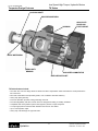
Torqmotor Design Features
COUPLING SHAFT
HIGH PRESSURE SEAL
HOUSING
HEAVY DUTY
DRIVE LINK
TOOTH SPLINE
DIRT & WATER SEAL
HEAVY DUTY
BEARING
HIGH SPEED COMMUTATOR
MATCHED ROTOR SET
TK Series features include:
• The roller vane rotor set design offers low-friction and wear compensation which maximizes the useful performance
life of the motor.
• Zero leak commutation valve provides greater, more consistent volumetric efficiency.
• Heavy duty spline geometry.
• Flow thru lubrication provides cooling extending motor life.
• Full interchangeability with other motors which are designed according to industry standards.
• Compatible with most hydraulic systems with regard to pressure, torque and speed.
• A unique high-pressure shaft seal that eliminates the need for case drains.
• Up to 73 horsepower output.
• Heavy duty roller bearings for high side loads.
4
Hydraulics
Parker Hannifin Corporation
Hydraulic Pump/Motor Division
Greeneville, TN 37745 USA
Low Speed High Torque, Hydraulic Motors
TK Series
HY13-1518-M1/USA
Introduction
This service manual has one purpose: to guide you in
maintaining, troubleshooting, and servicing the TK
Torqmotor (low-speed, high-torque hydraulic motor).
Material in this manual is organized so you can work on
the Torqmotor and get results without wasting time or
being confused. To get these results, you should read
this entire manual before you begin any work on the
Torqmotor.
This manual also contains troubleshooting information
and checklist. If you must service the Torqmotor, the
checklist will help you to determine where the problem
may be.
The three-column format of the Disassembly and
Inspection, and Assembly sections will make it easier
for you to conduct major work on the Torqmotor. Column
1 gives a brief key for each procedure. Column 2
explains in detail the procedure you should follow.
Column 3 illustrates this procedure with photographs.
Read all material carefully and pay special attention to
the notes, cautions, and warnings.
A page with the Torqmotor exploded assembly view is
provided several places in this manual. The component
part names and item numbers assigned on this exploded assembly view correspond with names and item
numbers (in parentheses) used in the disassembly and
assembly procedures set forth in this manual.
Service part list charts are also provided in this manual
with the part names and exploded view item numbers
cross referenced to Parker service part numbers.
Service parts are available through the Original Equipment Manufacturer or Parker approved TK Distributors.
As you gain experience in servicing the Torqmotor, you
may find that some information in this manual could be
clearer or more complete. If so, let us know about it. Do
not try to second guess the manual. If you are stuck,
contact us. Servicing the Torqmotor should be a safe and
productive procedure, in order for the unit to deliver the
reliable, long-life operation engineered into it.
5
Hydraulics
Parker Hannifin Corporation
Hydraulic Pump/Motor Division
Greeneville, TN 37745 USA
HY13-1518-M1/USA
Troubleshooting Guide
Low Speed High Torque, Hydraulic Motors
TK Series
NOTE: Before troubleshooting any system problem, check service literature published by the equipment and/or
component manufacturers. Follow their instructions, if given, for checking any component other than the Torqmotor
unit.
Preparation
Hydraulic Components
Make your troubleshooting easier by preparing as
follows:
• work in a clean, well-lighted place;
• have proper tools and materials nearby;
• have an adequate supply of clean petroleum-based
solvent.
If you think the problem is caused by a hydraulic
component, start by checking the easy-to-reach items.
Check all hoses and lines for cracks, hardening, or
other signs of wear. Reroute any usable hoses that are
kinked, severely bent, or that rest against hot engine
parts. Look for leaks, especially at couplings and
fittings. Replace any hoses or lines that don’t meet
system flow and pressure ratings.
Next, go to the reservoir and filter or filters. Check fluid
level and look for air bubbles. Check the filter(s). A filter
with a maximum 50 micron filtration is recommended for
the Torqmotor system.
Visually check other components to see if they are
loosely mounted, show signs of leaks, or other damage
or wear.
Excessive heat in a hydraulic system can create
problems that can easily be overlooked. Every system
has its limitation for the maximum amount of temperature. After the temperature is attained and passed, the
following can occur:
• oil seal leaks
• loss of efficiency such as speed and torque
• pump loss of efficiency
• pump failure
• hoses become hard and brittle
• hose failure
WARNING: SINCE SOLVENTS ARE FLAMMABLE, BE
EXTREMELY CAREFUL WHEN USING ANY SOLVENT, EVEN A SMALL EXPLOSION OR FIRE COULD
CAUSE INJURY OR DEATH.
WARNING: WEAR EYE PROTECTION AND BE SURE
TO COMPLY WITH OSHA AND OTHER MAXIMUM AIR
PRESSURE REQUIREMENTS.
Preliminary Checks
Hydraulic systems are often trouble-free. Hence, the
problem an operator complains of could be cause by
something other than the hydraulic components.
Thus, once you have determined that a problem exists,
start with the easy-to-check items, such as:
• parts damaged from impact that were not properly
repaired, or that should have been replaced; and
• improper replacement parts used in previous
servicing
• mechanical linkage problems such as binding,
broken, or loose parts or slipping belts
A normal temperature range means an efficient hydraulic system. Consult the manuals published by equipment and/or component manufacturers for maximum
allowable temperature and hydraulic tests that may be
necessary to run on the performance of the hydraulic
components. The Torqmotor is not recommended for
hydraulic systems with maximum temperatures above
200°F (93.3°C).
6
Hydraulics
Parker Hannifin Corporation
Hydraulic Pump/Motor Division
Greeneville, TN 37745 USA
Low Speed High Torque, Hydraulic Motors
TK Series
HY13-1518-M1/USA
Troubleshooting Checklist
Trouble
Cause
Remedy
Oil Leakage
1. Hose fittings loose, worn or
damaged.
Check & replace damaged
fittings or “O” Rings. Torque to
manufacturers specifications.
2.Oil seal rings (5) deteriorated by
excess heat.
Replace oil seal rings by disassembling
Torqmotor unit.
3.Special bolt (1)
loose or its sealing area
deteriorated by corrosion.
(a) Loosen then tighten single bolt to
torque specification.
(b) Replace bolt.
Significant loss of
speed under load
4.Internal shaft seal (18) worn or
damaged.
Replace seal. Disassembly of Torqmotor unit
necessary.
5.Worn coupling shaft (14) and
internal seal (18).
Replace coupling shaft and seal by
disassembling Torqmotor unit.
1. Lack of sufficient oil supply
(a) Check for faulty relief valve and
adjust or replace as required.
(b) Check for and repair worn pump.
(c) Check for and use correct oil for
temperature of operation.
Low mechanical
efficiency or undue
high pressure
required to operate
Torqmotor unit
2.High internal motor leakage
Replace worn rotor set by disassembling
Torqmotor unit.
3.Severely worn or damaged
internal splines.
Replace rotor set, drive link and coupling
shaft by disassembling Torqmotor unit.
4.Excessive heat.
Locate excessive heat source (usually a
restriction) in the system and correct the
condition.
1. Line blockage
Locate blockage source and repair or
replace.
2.Internal interference
Disassemble Torqmotor unit, identify and
remedy cause and repair, replacing parts as
necessary.
3.Lack of pumping pressure
Check for and repair worn pump.
4.Excessive binding or loading in
system external to Torqmotor
unit.
Locate source and eliminate cause.
CAUTION: If the hydraulic system fluid becomes overheated [in excess of 200°F (93.3°C)], seals in the system
can shrink, harden or crack, thus losing their sealing ability.
7
Hydraulics
Parker Hannifin Corporation
Hydraulic Pump/Motor Division
Greeneville, TN 37745 USA
Low Speed High Torque, Hydraulic Motors
Tools and Materials Required for Servicing TK Series
HY13-1518-M1/USA
•
•
•
•
•
•
•
•
•
•
•
•
•
•
•
•
Clean, petroleum-based solvent
Emery paper
Vise with soft jaws
Air pressure source
Arbor press
Screw driver
Masking tape
Breaker bar
Torque wrench-ft. lbs. (N m)
Sockets: 1/2 or 9/16 inch thin wall, 1 inch
Allen Sockets: 3/16, 3/8 inch
Adjustable crescent wrench or hose fitting wrenches
SAE 10W40 SE or SF oil
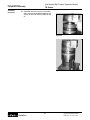
Special bearing mandrel for TK Torqmotor (SEE FIGURE 1)
Feeler gage .005 inch (.13 mm)
TK Torqmotor requires blind hole bearing puller for a 1.750 inch dia. (44.45 mm) and 2.750 inch dia. (69.85 mm)
bearings.
• Clean corrosion resistant grease. Part #406018 is included in each seal kit. Recommended grease is Parker
Specification #045236 or Mobil Mobilith SHC® 460
NOTE: The available service seal kits include the recommended grease as a grease pack #406018
CAUTION: Mixing greases that have different bases can be detrimental to bearing life.
8
Hydraulics
Parker Hannifin Corporation
Hydraulic Pump/Motor Division
Greeneville, TN 37745 USA
Low Speed High Torque, Hydraulic Motors
TK Series
HY13-1518-M1/USA
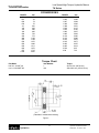
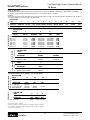
Technical Information
CONVERSIONS
INCHES
.020
.021
.029
.030
.111
.119
.152
.160
.296
.304
.460
.470
.500
.585
.595
.660
.675
1.058
mm
.51
.53
.74
.76
2.81
3.02
3.86
4.06
7.52
7.72
11.68
11.94
12.70
14.86
15.11
16.76
17.15
26.87
INCHES
1.060
1.295
1.297
1.396
1.398
1.620
1.622
1.983
1.985
2.120
2.122
2.233
2.235
2.483
2.485
2.500
2.88
mm
26.92
32.89
32.94
35.46
35.51
41.15
41.20
50.37
50.42
53.85
53.90
56.72
56.77
63.07
63.12
63.5
73.2
Torque Chart
Part Name
bolt 3/8 24 UNF 2A
nut 1-1/4 18 UNEF 2B
Item Number
1
14b
Torque
45-55 ft. lbs. (60-76 N m)
350-450 ft. lbs. (475-610 N m)
2.988
2.986
1.748
1.746
2.748
2.746
3.60
3.122
3.120
.420"
.410"
.150
.130
(Fabricate if considered necessary)
Figure 1
9
Hydraulics
Parker Hannifin Corporation
Hydraulic Pump/Motor Division
Greeneville, TN 37745 USA
Low Speed High Torque, Hydraulic Motors
TK Series
HY13-1518-M1/USA
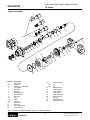
Exploded View
Typical Assembly
11
5
14b
13
14a
12
14
1
15
16
17
20
19
18
16
4
9a
5
9b
21
3
6
22
5
23
9c
9
Matched
Set
8
7
5
10
Item No.
1
2
3
4
5
6
7
8
9
9a
9b
9c
10
11
12
13
Description
Special Bolt
Endcover
Seal Ring - Commutator
Commutator
Seal Ring
Manifold
Retaining Ring
Rotor Washer
Rotor Set
Rotor
Stator
Vane (9)
Wear Plate
Drive Link
Retaining Washer
Thrust Bearing
14
14a
14b
15
16
17
18
19
20
21
22
23
Coupling Shaft
Key
Nut
Radial Bearing
Thrust Washer
Thrust Bearing
Shaft Seal
Back Up Washer
Back Up Ring
Housing
Radial Bearing
Dirt & Water Seal
Note: See “Service Parts List Chart” page 11 for all part numbers.
10
Hydraulics
Parker Hannifin Corporation
Hydraulic Pump/Motor Division
Greeneville, TN 37745 USA
2
Low Speed High Torque, Hydraulic Motors
TK Series
HY13-1518-M1/USA
Service Parts List Chart
SERIES
Chart Use Example:
TK0200K5320AAAB Torqmotor includes part numbers listed to the right of TK (SERIES), 0200 (DISP.), K (MOUNTING), 5 (PORTING),
32 (SHAFT), 0 (ROTATION), and AAAB (OPTION) shown in the left hand column of the chart.
Caution:
The charted component service information is for the Torqmotors listed only. Refer to the original equipment manufacturer of the equipment
using the Torqmotor for assembly numbers not listed below.
EXPLODED VIEW
ITEM #
4
6
10
13
15
16
17
19
20
22
23
DESCRIPTION
TK-Service Part #
MANIFOLD WEAR
COMMUTATOR (SEE NOTE) PLATE
TK014000
TK015000 477983 070029
Mounting Code
KT-
1
073007 069033 (2)
8
STATOR
THICKNESS
.6882
.8601
1.0836
1.3761
1.7199
2.1668
2.7522
3.4398
BOLT (7)
021472
021378
021366
021394
021473
021474
021388
021475
THRUST BACKUP
BEARING WASHER
BACKUP
RING
OUTER DIRT & WATER
BEARING
SEAL
070028
032851
070027
028549
DRIVE
DRIVE LINK
LINK
L DIM
TK02003000
5.520
TK02503000
5.692
TK03153000
5.916
TK04003000
6.209
TK05003000
6.553
TK06303000
7.000
TK08003000
7.585
TK10003000
8.273
DESCRIPTION
21
SERVICE
HOUSING
HOUSING
ASSEMBLY
SAE CC (4 Bolt)
Wheel Mt. (4 Bolt)
TK012002
TK012001
TK012002A1
TK012001A1
EXPLODED VIEW
ITEM #
478082
11
ROTOR
SET
TK02007003
TK02507003
TK03157003
TK04007003
TK05007003
TK06307003
TK08007003
TK10007003
EXPLODED VIEW
ITEM #
2
END
COVER
Porting Code
REAR HOUSING*
FRONT HOUSING
DISPLACEMENT GROUP
EXPLODED VIEW
ITEM #
DISPLACEMENT
(in3/rev)
0200- 12.2
0250- 15.3
0315- 19.2
0400- 24.4
0500- 30.5
0630- 38.4
0800- 48.8
1000- 61.0
THRUST
INNER
THRUST
BEARING BEARING WASHER(2)
DESCRIPTION
54-
Rear Port (1 5/16" O-Ring; Radial)
Rear Port (Manifold; Radial)
TK016000
TK016001
OPTION GROUP
Shaft Code
COUPLING SHAFT GROUP
*TK Series Motors only available in rear ported option.
EXPLODED VIEW
ITEM #
14
14b
KEY
039040
NUT
039049
039050
025133
COUPLING
DESCRIPTION
32- 1-1/2" Straight Key
36- 17 Tooth Spline
63- 1-3/4" Tapered Shaft
64- 40mm Straight Key
SHAFT
TK019002
TK019003
TK019001
TK019004
EXPLODED VIEW
ITEM #
AAAA
14a
DESCRIPTION
Black Paint
3
4
16
COMMUTATOR SEAL
INNER
SEAL
RING (5) SEAL
032852 032807 032850
For reverse timed manifold, use TK015001.
Standard seal kit SK000167 includes five #032807 seal rings, #032852 commutator seal, #032850
inner seal, #028549, #032851 backup washer, backup ring, #478082 dirt & water seal, #406018
grease pack and bulletin #050034.
11
Hydraulics
Parker Hannifin Corporation
Hydraulic Pump/Motor Division
Greeneville, TN 37745 USA
HY13-1518-M1/USA
Disassembly and Inspection
Low Speed High Torque, Hydraulic Motors
TK Series
Preparation Before Disassembly
• Before you disassemble the Torqmotor unit or any of its components read this entire manual. It provides important
information on parts and procedures you will need to know to service the Torqmotor.
• Refer to “Tools and Materials Required for Services” section for tools and other items required to service the
Torqmotor and have them available.
• Thoroughly clean off all outside dirt, especially from around fittings and hose connections, before disconnecting
and removing the Torqmotor. Remove rust or corrosion from coupling shaft.
• Remove coupling shaft connections and hose fittings and immediately plug port holes and fluid lines.
• Remove the Torqmotor from system, drain it of fluid and take it to a clean work surface.
• Clean and dry the Torqmotor before you start to disassemble the unit.
• As you disassemble the Torqmotor clean all parts, except seals, in clean petroleum-based solvent, and blow them
dry.
WARNING: petroleum-base solvents are flammable. Be extremely careful when using any solvent. Even a small
explosion or fire could cause injury or death.
WARNING: WEAR EYE PROTECTION AND BE SURE TO COMPLY WITH OSHA OR OTHER MAXIMUM AIR
PRESSURE REQUIREMENTS.
CAUTION: Never steam or high pressure wash hydraulic components. Do not force or abuse closely fitted parts.
• Keep parts separate to avoid nicks and burrs.
• Discard all seals and seal rings as they are removed from the Torqmotor. Replace all seals, seal rings and any
damaged or worn parts with genuine Parker or OEM approved service parts.
CAUTION: Special lifting aids may be required to handle/service the TK motor due to it’s large size and weight.
Take steps necessary to ensure that handling/service can be done safely.
12
Hydraulics
Parker Hannifin Corporation
Hydraulic Pump/Motor Division
Greeneville, TN 37745 USA
Low Speed High Torque, Hydraulic Motors
TK Series
HY13-1518-M1/USA
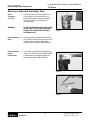
Disassembly and Inspection
Reference Exploded Assembly View
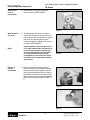
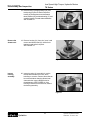
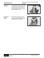
Place
Torqmotor
in a vise
1. Place the Torqmotor in a soft jawed vice or
similar support, with coupling shaft (14)
pointed down and the vise jaws clamping
firmly on the sides of the housing (21)
mounting flange.
WARNING
IF THE TORQMOTOR IS NOT FIRMLY HELD
IN THE VISE, IT COULD BE DISLODGED
DURING THE SERVICE PROCEDURES,
CAUSING INJURY.
Figure 2
Scribe alignment 2. Scribe an alignment mark down and across
mark
the Torqmotor components from end cover (2)
to housing (21) to facilitate reassembly
orientation where required. SEE FIGURE 2.
Remove special
bolts &
inspect bolts
3. Remove the nine special hex head bolts (1)
using a 9/16 inch size socket. SEE FIGURE
3. Inspect bolts for damaged threads. Replace damaged bolts. SEE FIGURE 4.
Figure 3
Figure 4
13
Hydraulics
Parker Hannifin Corporation
Hydraulic Pump/Motor Division
Greeneville, TN 37745 USA
HY13-1518-M1/USA
Disassembly and Inspection
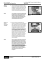
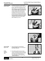
Remove end
cover &
inspect bolts
Low Speed High Torque, Hydraulic Motors
TK Series
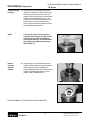
4. Remove end cover (2) and seal ring (5).
Discard seal ring. SEE FIGURE 5.
Figure 5
Wash & inspect
end cover
NOTE
Remove &
inspect
commutator
6. Thoroughly wash end cover (2) in proper
solvent and blow dry. Be sure the end cover
flow areas, are free of contamination. Inspect
end cover for cracks and the bolt head
recesses for damage. Replace end cover as
necessary. SEE FIGURE 6.
A polished pattern (not scratches) on the
cover from rotation of the commutator (4)
is normal. Discoloration would indicate
excess fluid temperature, thermal shock,
or excess speed and require system
investigation for cause and close inspection of end cover, commutator, manifold,
and rotor set.
Figure 6
8. Remove commutator (4) and seal ring (3)
Remove seal ring from commutator, using an
air hose to blow air into ring groove until seal
ring is lifted out and discard seal ring. Inspect
commutator for cracks or burrs, wear, scoring,
spalling or brinelling. If any of these conditions
exist, replace commutator. SEE FIGURE 7 &
8.
Figure 7
Figure 8
14
Hydraulics
Parker Hannifin Corporation
Hydraulic Pump/Motor Division
Greeneville, TN 37745 USA
Low Speed High Torque, Hydraulic Motors
TK Series
HY13-1518-M1/USA
Disassembly and Inspection
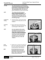
Remove
manifold
NOTE
Remove &
inspect
rotor set &
wearplate
NOTE
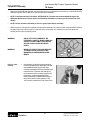
9. Remove manifold (6) and inspect for cracks
surface scoring, brinelling or spalling. Replace
manifold if any of these conditions exist. SEE
FIGURE 9. A polished pattern on the ground
surface from commutator or rotor rotation is
normal. Remove and discard the seal ring (5).
The manifold is constructed of plates bonded
together to form an integral component not
subject to further disassembly for service.
Compare configuration of both sides of the
manifold to ensure that same surface is
reassembled against the rotor set.
10. Remove rotor set (9) and wearplate (10),
together to retain the rotor set in its assembled
form, maintaining the same rotor vane (9c) to
stator (9b) contact surfaces. SEE FIGURE 10.
The drive link (11) may come away from the
coupling shaft (14) with the rotor set, and
wearplate. You may have to shift the rotor set
on the wearplate to work the drive link out of
the rotor (9a) and wearplate. Inspect the rotor
set in its assembled form for nicks, scoring, or
spalling on any surface and for broken or worn
splines. If the rotor set component requires
replacement, the complete rotor set must be
replaced as it is a matched set. Inspect the
wearplate for cracks, brinelling, or scoring.
Discard seal rings (5) between the rotor set,
and the wearplate.
Figure 9
Figure 10
The rotor set (9) components may become
disassembled during service procedures.
Marking the surface of the rotor and stator
that is facing UP, with etching ink or grease
pencil before removal from Torqmotor will
ensure correct reassembly of rotor into
stator and rotor set into Torqmotor. Marking
all rotor components and mating spline
components for exact repositioning at
assembly will ensure maximum wear life
and performance of rotor set and
Torqmotor.
15
Hydraulics
Parker Hannifin Corporation
Hydraulic Pump/Motor Division
Greeneville, TN 37745 USA
HY13-1518-M1/USA
Disassembly and Inspection
Low Speed High Torque, Hydraulic Motors
TK Series
NOTE
Series TK Torqmotor may have a rotor set
with two stator halves (9B) with a seal ring
(5) between them. Discard seal ring only if
stator halves become disassembled during
the service procedures.
NOTE
A polished pattern on the wear plate from
rotor rotation is normal.
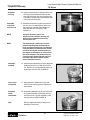
Check rotor,
vane clearance
NOTE
Remove &
inspect
drive link
Remove thrust
bearing
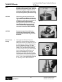
11. Place rotor set (9) and wear plate (10) on a
flat surface and center rotor (9a) in stator (9b)
such that two rotor lobes (180 degrees apart)
and a roller vane (9c) centerline are on the
same stator centerline. Check the rotor lobe
to roller vane clearance with a feeler gage at
this common centerline. If there is more than
.005 inches (0.13 mm) of clearance, replace
rotor set. SEE FIGURE 11.
Figure 11
If rotor set (9) has two stator halves (9b),
check the rotor lobe to roller vane clearance at both ends of rotor.
12. Remove drive link (11) from coupling shaft
(14) if it was not removed with rotor set and
wear plate. Inspect drive link for cracks and
worn or damaged splines. No perceptible lash
(play) should be noted between mating spline
parts. SEE FIGURE 12. Remove and discard
seal ring (5) from housing (21).
Figure 12
13. Remove rear thrust bearing (13) and retaining
washer (12) from top of coupling shaft (14).
Inspect for wear, brinelling, corrosion and a
full complement of retained rollers. SEE
FIGURE 13.
Figure 13
16
Hydraulics
Parker Hannifin Corporation
Hydraulic Pump/Motor Division
Greeneville, TN 37745 USA
Low Speed High Torque, Hydraulic Motors
TK Series
HY13-1518-M1/USA
Disassembly and Inspection
Check coupling
shaft for rust
or corrosion
14. Check exposed portion of coupling shaft (14)
to be sure you have removed all signs of rust
and corrosion which might prevent its
withdrawal through the seal and bearing.
Crocus cloth or fine emery paper may be
used. Remove any key (14A), nut (14B),
washer, bolt, or lock washer still attached to
the shaft.
Remove &
inspect
coupling shaft
15. Remove coupling shaft (14), by pushing on
the output end of shaft. SEE FIGURE 14.
Inspect coupling shaft bearing and seal
surfaces for spalling, nicks, grooves, severe
wear or corrosion and discoloration. Inspect
for damaged or worn internal and external
splines or keyway. SEE FIGURE 15. Replace
coupling shaft if any of these conditions
exist.
NOTE
Minor shaft wear in seal area is
permissible. If wear exceeds .020 inches
(0.51 mm) diametrically, replace coupling
shaft.
NOTE
A slight “polish” is permissible in the
shaft bearing areas. Anything more would
require coupling shaft replacement.
Figure 14
Figure 15
17
Hydraulics
Parker Hannifin Corporation
Hydraulic Pump/Motor Division
Greeneville, TN 37745 USA
HY13-1518-M1/USA
Disassembly and Inspection
Low Speed High Torque, Hydraulic Motors
TK Series
18. Remove seal (18), backup washer (19), and
backup ring (20) from TK Series Torqmotor
housing by working them around unseated
thrust washers (16) and thrust bearing (17) and
out of the housing. Discard seal and washers.
SEE FIGURE 16.
Figure 16
Remove dirt
& water seal
19. Remove housing (21) from vise, invert it and
remove and discard seal (23). A blind hole
bearing or seal puller is required.
SEE FIGURE 17.
Figure 17
Inspect
housing
assembly
20. Inspect housing (21) assembly for cracks,
the machined surfaces for nicks, burrs,
brinelling or corrosion. Remove burrs that can
be removed without changing dimensional
characteristics. Inspect tapped holes for
thread damage. SEE FIGURE 18. If the
housing is defective in these areas, discard
the housing assembly.
Figure 18
18
Hydraulics
Parker Hannifin Corporation
Hydraulic Pump/Motor Division
Greeneville, TN 37745 USA
Low Speed High Torque, Hydraulic Motors
TK Series
HY13-1518-M1/USA
Disassembly and Inspection
Inspect housing
bearings
NOTE
21. If the housing (21) assembly has passed
inspection to this point, inspect the housing
bearings (22) and (15) and since they are
captured in the housing cavity, the two thrust
washers (16) and thrust bearing (17). The
bearing rollers must be firmly retained in the
bearing cages, but must rotate and orbit
freely. All rollers and thrust washers must be
free of brinelling and corrosion.
The depth or location of bearing (15) in
relation to the housing wear plate surface
should be measured and noted before
removing the bearings. This will facilitate
the correct reassembly of new bearings.
SEE FIGURE 19.
Figure 19
Remove
bearings
& thrust
washers
22. If the bearings, or thrust washers must be
replaced use a suitable size bearing puller to
remove bearing (15) from housing (21)
without damaging the housing. Remove thrust
washers (16) and thrust bearing (17) and
replace. SEE FIGURES 20 & 21.
Figure 20
THE DISASSEMBLY OF TORQMOTOR IS NOW COMPLETE.
Figure 21
19
Hydraulics
Parker Hannifin Corporation
Hydraulic Pump/Motor Division
Greeneville, TN 37745 USA
HY13-1518-M1/USA
Torqmotor Assembly
Low Speed High Torque, Hydraulic Motors
TK Series
•
Replace all seals and seal rings with new ones each time you reassemble the Torqmotor unit. Lubricate all seals
and seal rings with SAE 10W40 oil or clean grease before assembly.
•
NOTE: Complete seal kits are available. SEE FIGURE 22. The parts should be available through most
OEM parts distributors or Parker approved Torqmotor distributors. (Contact your local dealer for availability).
•
NOTE: Unless otherwise indicated, do not oil or grease parts before assembly.
•
Wash all parts in clean petroleum-based solvents before assembly. Blow them dry with compressed air. Remove
any paint chips from mating surfaces of the end cover, commutator set, manifold rotor set, wear plate and
housing and from port and sealing areas.
WARNING
WARNING
SINCE THEY ARE FLAMMABLE, BE
EXTREMELY CAREFUL WHEN USING ANY
SOLVENT. EVEN A SMALL EXPLOSION
OR FIRE COULD CAUSE INJURY OR
DEATH.
WEAR EYE PROTECTION AND BE SURE
TO COMPLY WITH OSHA OR OTHER
MAXIMUM AIR PRESSURE REQUIREMENTS.
5
23
3
20
19
18
Figure 22 Seal Kit
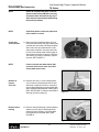
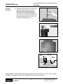
Press in outer
bearing
1. If the housing (21) bearing components were
removed for replacement, thoroughly coat and
pack a new outer bearing (22) with clean
corrosion resistant grease recommended in the
material section. Press the new bearing into
the counterbore at the mounting flange end of
the housing, using the appropriate sized
bearing mandrel such as described in figure 1
which will control the bearing depth to .410/
.420” from the outside face of the counter bore.
Figure 23
20
Hydraulics
Parker Hannifin Corporation
Hydraulic Pump/Motor Division
Greeneville, TN 37745 USA
Low Speed High Torque, Hydraulic Motors
TK Series
HY13-1518-M1/USA
Torqmotor Assembly
NOTE
Bearing mandrel must be pressed against
the lettered end of bearing shell. Take care
that the housing bore is square with the
press base and the bearing is not cocked
when pressing a bearing into the housing.
CAUTION
If the bearing mandrel specified in the
“Tools and Materials Required for Servicing” section is not available and alternate
methods are used to press in bearing (15)
or (22) be careful to ensure that the
bearing depths specified are achieved to
insure adequate bearing support and
correct relationship to adjacent components when assembled. SEE FIGURE 24.
CAUTION
Figure 24
Because bearings (15) and (22) have a
press fit into the housing they must be
discarded when removed. They must not
be reused.
Figure 25
Press in inner
bearing
2. The Large Frame TK Series Torqmotor
housing (21) requires that you assemble a
new backup washer (19), new seal (18), with
the lip facing to the inside of Torqmotor (see
figure 45), new thrust washer (16), new
thrust bearing (17) and a new second thrust
washer (16) in that order before pressing in
the inner housing bearing (15). SEE FIGURE
25 & 26. When these components are in
place, press new bearing (15) into the
housing (21) to a depth of .130/.150 inches.
Use the opposite end of the bearing mandrel
used to press in outer bearing (22). Reference
figure 1, in the “Tools and Materials Required
for Servicing” section. SEE FIGURE 27.
Figure 26
Figure 27
21
Hydraulics
Parker Hannifin Corporation
Hydraulic Pump/Motor Division
Greeneville, TN 37745 USA
HY13-1518-M1/USA
Torqmotor Assembly
Press in dirt &
water seal
Low Speed High Torque, Hydraulic Motors
TK Series
3. Press a new dirt and water seal (23) into the
housing (21) outer bearing counterbore. The
dirt and water seal (23) must be pressed in
with the lip facing out and until the seal is
flush to .020 inches (.51 mm) below the end
of housing. SEE FIGURE 28.
Figure 28
Place housing
assembly
into vice
4. Place housing (21) assembly into a soft
jawed vise or similar support with the coupling shaft bore down, clamping against the
mounting flange. SEE FIGURE 29.
Figure 29
22
Hydraulics
Parker Hannifin Corporation
Hydraulic Pump/Motor Division
Greeneville, TN 37745 USA
Low Speed High Torque, Hydraulic Motors
TK Series
HY13-1518-M1/USA
Torqmotor Assembly
Assemble backup
washers & seal
Housings (21) that did not require replacement of the bearing package will require that
the two “captured” thrust washers (16) and
thrust bearing (17) be unseated and vertical
to the counterbore and the new backup ring
(20), new backup washer (19), and new seal
(18) be worked around the thrust bearing
package and placed into their respective
counterbores. The seal lip must face out of
the seal counterbore and toward the inside of
Torqmotor (see figure 45). Be sure the thrust
bearing package is reseated correctly after
assembly of the seal and backup washer.
SEE FIGURES 30, 31 & 32.
Figure 30
Figure 31
Figure 32
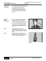
Apply masking
tape to shaft
7. Apply masking tape around splines or
keyway on shaft (14) to prevent damage to
seal. SEE FIGURE 33.
Install
coupling
shaft
8. Be sure that a generous amount of clean
corrosion resistant grease has been applied to
the lower (outer) housing bearing (22). Install
the coupling shaft (14) into housing (21),
seating it against the second thrust washer
(16). SEE FIGURE 33.
23
Hydraulics
Figure 33
Parker Hannifin Corporation
Hydraulic Pump/Motor Division
Greeneville, TN 37745 USA
HY13-1518-M1/USA
Torqmotor Assembly
Low Speed High Torque, Hydraulic Motors
TK Series
CAUTION
The outer bearing (22) is not lubricated by the
system’s hydraulic fluid. Be sure it is thoroughly
packed with the recommended grease, Parker Gear
grease specification #045236, E/M Lubricant #K70M or Mobil Mobilith SHC ® 460 A packet of
grease (P/N 406018) is included in each seal kit.
NOTE
The coupling shaft (14) will be approximately .10 inch (2.54 mm) below the
housing wear plate surface when correctly
installed to allow the assembly of thrust
bearing (13) and retaining washer (12). The
coupling shaft must rotate smoothly on the
thrust bearing package.
Install thrust
bearing
9. Install thrust bearing (13) and retaining washer
(12) onto the end of coupling shaft (14). SEE
FIGURE 34.
Insert seal
ring
10. Apply a small amount of clean grease to a
new seal ring (5) and insert it into the housing
(21) seal ring groove. SEE FIGURE 35.
NOTE
One or two alignment studs screwed
finger tight into housing (21) bolt holes,
approximately 180 degrees apart, will
facilitate the assembly and alignment of
components as required in the following
procedures. The studs can be made by
cutting off the heads of 3/8-24 UNF 2A
bolts that are over .5 inch (12.7 mm)
longer than the bolts (1) used in the
Torqmotor.
Figure 34
Figure 35
Install
drive link
NOTE
11. Install drive link (11) with the long splined end
down into the coupling shaft (14) and engage
the drive link splines into mesh with the
coupling shaft splines. SEE FIGURE 36.
Use any alignment marks put on the
coupling shaft and drive link before
disassembly to assemble the drive link
splines in their original position in the
mating coupling shaft splines.
Figure 36
24
Hydraulics
Parker Hannifin Corporation
Hydraulic Pump/Motor Division
Greeneville, TN 37745 USA
Low Speed High Torque, Hydraulic Motors
TK Series
HY13-1518-M1/USA
Torqmotor Assembly
Assemble
seal ring
Assemble
wear plate
and rotor set
12. Apply a small amount of clean grease to new
seal rings (5) and assemble them into the
seal ring grooves on the rotor set side of the
wear plate (10) and on the manifold plate side
of the rotor set stator (9B).
13. Assemble wear plate (10) with rotor set over
the drive link (11) and alignment studs onto
the housing (21) and the rotor splines into
mesh with the drive link splines. SEE
FIGURE 37.
NOTE
It may be necessary to turn one
alignment stud out of the housing (21)
temporarily to assemble rotor set (9)
over the drive link.
NOTE
The manifold (6) is made up of several
plates bonded together permanently to
form an integral component. The manifold
surface that must contact the rotor set has
it’s series of irregular shaped cavities on
the largest circumference or circle around
the inside diameter. The polished impression left on the manifold by the rotor set
is another indication of which surface
must contact the rotor set.
Assemble
manifold
16. Assemble the manifold (6) over the alignment
studs and drive link (11) and onto the rotor
set. Be sure the correct manifold surface is
against the rotor set. SEE FIGURE 38.
Insert a seal
in manifold
17. Apply grease to a new seal ring (5) and
insert it in the seal ring groove exposed on
the manifold.
Assemble
seal &
commutator
19. Assemble a new seal ring (3) into commutator (4) and assemble commutator over the
end of drive link (11) onto manifold (6) with
seal ring side up. SEE FIGURE 39.
Note
Figure 37
Figure 38
Remove alignment studs (if used) prior to
assembly of end cover.
Figure 39
25
Hydraulics
Parker Hannifin Corporation
Hydraulic Pump/Motor Division
Greeneville, TN 37745 USA
HY13-1518-M1/USA
Torqmotor Assembly
Assemble
end cover
Low Speed High Torque, Hydraulic Motors
TK Series
22. Assemble end cover over the commutator
and in line with the alignment marks on the
exterior of the motor. SEE FIGURE 40 and
41.
Figure 40
Figure 41
26
Hydraulics
Parker Hannifin Corporation
Hydraulic Pump/Motor Division
Greeneville, TN 37745 USA
Low Speed High Torque, Hydraulic Motors
TK Series
HY13-1518-M1/USA
Torqmotor Assembly
Assemble
cover bolts
23. Assemble the 9 special bolts (1) and screw in
finger tight. Remove and replace the two
alignment studs with bolts after the other
bolts are in place. Alternately and progressively tighten the bolts (SEE FIGURE 44),to
pull the end cover and other components into
place with a final torque of 44-55 ft. lbs. on
each bolt. SEE FIGURE 42 & 43.
Figure 42
Figure 43
2
9
4
7
6
5
8
1
3
Figure 44
Thrust
Washers
Housing
Backup
Washer
Seal
Backup
Ring
Thrust
Bearing
Not To Scale
Figure 45
Shaft
Large Frame
THE ASSEMBLY OF THE TORQMOTOR IS NOW COMPLETE EXCEPT FOR KEY (14A), NUT (14B), or OTHER
EXTERNAL HARDWARE IF APPLICABLE. PROCEED TO FINAL CHECKS SECTION.
27
Hydraulics
Parker Hannifin Corporation
Hydraulic Pump/Motor Division
Greeneville, TN 37745 USA
HY13-1518-M1/USA
Final Checks
Low Speed High Torque, Hydraulic Motors
TK Series
Final Checks
•
Pressurize the Torqmotor with 100 p.s.i. dry air or nitrogen and submerge in solvent to check for
external leaks.
•
Check Torqmotor for rotation. Torque required to rotate coupling shaft should not be more than
50 ft. lbs. (68 N m)
•
On TK Series Torqmotor, pressure port with “A” cast under it on endcover (2) is for clockwise
coupling shaft rotation as viewed from the output end of coupling shaft. Pressure port with “B” cast under
it is for counter clockwise coupling shaft rotation.
•
Use test stand if available, to check operation of the Torqmotor.
Hydraulic Fluid
Keep the hydraulic system filled with one of the following:
•
10W40 SE or SF manufacturers suggested oil.
•
Hydraulic fluid as recommended by equipment manufacturer, but the viscosity should not drop below 50 SSU or
contain less than .125% zinc anti-wear additives.
CAUTION: Do not mix oil types. Any mixture, or an unapproved oil, could deteriorate the seals. Maintain
the proper fluid level in the reservoir. When changing fluid, completely drain old oil from the system. It
is suggested also that you flush the system with clean oil.
Filtration
Recommended filtration 20-50 micron.
Oil Temperature
Maximum operating temperature 200°F (93.3° C).
28
Hydraulics
Parker Hannifin Corporation
Hydraulic Pump/Motor Division
Greeneville, TN 37745 USA
Low Speed High Torque, Hydraulic Motors
TK Series
HY13-1518-M1/USA
Tips
Tips for Maintaining the Torqmotor Hydraulic System
•
Adjust fluid level in reservoir as necessary.
•
Encourage all operators to report any malfunction or accident that may have damaged the hydraulic system
or component.
•
Do not attempt to weld any broken Torqmotor component. Replace the component with original equipment only.
•
Do not cold straighten, hot straighten, or bend any Torqmotor part.
•
Prevent dirt or other foreign matter from entering the hydraulic system. Clean the area around and the filler caps
before checking oil level.
•
Investigate and correct any external leak in the hydraulic system, no matter how minor the leak.
•
Comply with manufacturer’s specifications for cleaning or replacing the filter.
CAUTION: Do not weld, braze, solder or any way alter any Torqmotor component.
CAUTION: Maximum operating pressure must not exceed recommended Torqmotor pressure capacity.
CAUTION: Always carefully inspect any system component that may have been struck or damaged
during operation or in an accident. Replace any component that is damaged or that is questionable.
CAUTION: Do not force any coupling onto the Torqmotor coupling shaft as this could damage the unit
internally.
Parker extends close technical cooperation and assistance. If problems occur which you cannot solve, please
contact your local Parker approved Distributor or Parker Technical Support. Our phone number and fax number
and address are on the back cover of this manual.
29
Hydraulics
Parker Hannifin Corporation
Hydraulic Pump/Motor Division
Greeneville, TN 37745 USA
HY13-1518-M1/USA
Notes
Low Speed High Torque, Hydraulic Motors
TK Series
30
Hydraulics
Parker Hannifin Corporation
Hydraulic Pump/Motor Division
Greeneville, TN 37745 USA
Low Speed High Torque, Hydraulic Motors
TK Series
HY13-1518-M1/USA
Offer of Sale
The items described in this document and other documents or descriptions provided by Parker Hannifin Corporation, its subsidiaries and its authorized
distributors are hereby offered for sale at prices to be established by Parker Hannifin Corporation, its subsidiaries and its authorized distributors. This
offer and its acceptance by any customer ("Buyer") shall be governed by all of the following Terms and Conditions. Buyer’s order for any such items,
when communicated to Parker Hannifin Corporation, its subsidiary or an authorized distributor ("Seller") verbally or in writing, shall constitute acceptance
of this offer.
1. Terms and Conditions of Sale: All descriptions, quotations, proposals,
offers, acknowledgments, acceptances and sales of Seller’s products are
subject to and shall be governed exclusively by the terms and conditions
stated herein. Buyer’s acceptance of any offer to sell is limited to these
terms and conditions. Any terms or conditions in addition to, or inconsistent with those stated herein, proposed by Buyer in any acceptance of
an offer by Seller, are hereby objected to. No such additional, different
or inconsistent terms and conditions shall become part of the contract
between Buyer and Seller unless expressly accepted in writing by Seller.
Seller’s acceptance of any offer to purchase by Buyer is expressly
conditional upon Buyer’s assent to all the terms and conditions stated
herein, including any terms in addition to, or inconsistent with those
contained in Buyer’s offer, Acceptance of Seller’s products shall in all
events constitute such assent.
2. Payment: Payment shall be made by Buyer net 30 days from the date
of delivery of the items purchased hereunder. Amounts not timely paid
shall bear interest at the maximum rate permitted by law for each month
or portion thereof that the Buyer is late in making payment. Any claims
by Buyer for omissions or shortages in a shipment shall be waived unless
Seller receives notice thereof within 30 days after Buyer’s receipt of the
shipment.
3. Delivery: Unless otherwise provided on the face hereof, delivery shall
be made F.O.B. Seller’s plant. Regardless of the method of delivery,
however, risk of loss shall pass to Buyer upon Seller’s delivery to a carrier.
Any delivery dates shown are approximate only and Seller shall have no
liability for any delays in delivery.
4. Warranty: Seller warrants that the items sold hereunder shall be free
from defects in material or workmanship for a period of 18 months from
date of shipment from Parker Hannifin Corporation. THIS WARRANTY
COMPRISES THE SOLE AND ENTIRE WARRANTY PERTAINING TO
ITEMS PROVIDED HEREUNDER. SELLER MAKES NO OTHER WARRANTY, GUARANTEE, OR REPRESENTATION OF ANY KIND WHATSOEVER. ALL OTHER WARRANTIES, INCLUDING BUT NOT LIMITED
TO, MERCHANTABILITY AND FITNESS FOR PURPOSE, WHETHER
EXPRESS, IMPLIED, OR ARISING BY OPERATION OF LAW, TRADE
USAGE, OR COURSE OF DEALING ARE HEREBY DISCLAIMED.
NOTWITHSTANDING THE FOREGOING, THERE ARE NO WARRANTIES WHATSOEVER ON ITEMS BUILT OR ACQUIRED WHOLLY OR
PARTIALLY, TO BUYER’S DESIGNS OR SPECIFICATIONS.
5. Limitation Of Remedy: SELLER’S LIABILITY ARISING FROM OR IN
ANY WAY CONNECTED WITH THE ITEMS SOLD OR THIS CONTRACT
SHALL BE LIMITED EXCLUSIVELY TO REPAIR OR REPLACEMENT OF
THE ITEMS SOLD OR REFUND OF THE PURCHASE PRICE PAID BY
BUYER, AT SELLER’S SOLE OPTION. IN NO EVENT SHALL SELLER
BE LIABLE FOR ANY INCIDENTAL, CONSEQUENTIAL OR SPECIAL
DAMAGES OF ANY KIND OR NATURE WHATSOEVER, INCLUDING
BUT NOT LIMITED TO LOST PROFITS ARISING FROM OR IN ANY WAY
CONNECTED WITH THIS AGREEMENT OR ITEMS SOLD HEREUNDER,
WHETHER ALLEGED TO ARISE FROM BREACH OF CONTRACT,
EXPRESS OR IMPLIED WARRANTY, OR IN TORT, INCLUDING WITHOUT LIMITATION, NEGLIGENCE, FAILURE TO WARN OR STRICT
LIABILITY.
6. Changes, Reschedules and Cancellations: Buyer may request to
modify the designs or specifications for the items sold hereunder as well
as the quantities and delivery dates thereof, or may request to cancel all
or part of this order, however, no such requested modification or
cancellation shall become part of the contract between Buyer and Seller
unless accepted by Seller in a written amendment to this Agreement.
Acceptance of any such requested modification or cancellation shall be
at Seller’s discretion, and shall be upon such terms and conditions as
Seller may require.
7. Special Tooling: A tooling charge may be imposed for any special
tooling, including without limitation, dies, fixtures, molds and patterns,
acquired to manufacture items sold pursuant to this contract. Such special
tooling shall be and remain Seller’s property notwithstanding payment of
any charges by Buyer. In no event will Buyer acquire any interest in
apparatus belonging to Seller which is utilized in the manufacture of the
items sold hereunder, even if such apparatus has been specially
converted or adapted for such manufacture and notwithstanding any
charges paid by Buyer. Unless otherwise agreed, Seller shall have the
right to alter, discard or otherwise dispose of any special tooling or other
property in its sole discretion at any time.
8. Buyer’s Property: Any designs, tools, patterns, materials, drawings,
confidential information or equipment furnished by Buyer or any other
items which become Buyer’s property, may be considered obsolete and
may be destroyed by Seller after two (2) consecutive years have elapsed
without Buyer placing an order for the items which are manufactured using
such property, Seller shall not be responsible for any loss or damage to
such property while it is in Seller’s possession or control.
9. Taxes: Unless otherwise indicated on the face hereof, all prices and
charges are exclusive of excise, sales, use, property, occupational or like
taxes which may be imposed by any taxing authority upon the manufacture, sale or delivery of the items sold hereunder. If any such taxes must
be paid by Seller or if Seller is liable for the collection of such tax, the amount
thereof shall be in addition to the amounts for the items sold. Buyer agrees
to pay all such taxes or to reimburse Seller therefore upon receipt of its
invoice. If Buyer claims exemption from any sales, use or other tax imposed
by any taxing authority, Buyer shall save Seller harmless from and against
any such tax, together with any interest or penalties thereon which may
be assessed if the items are held to be taxable.
10. Indemnity For Infringement of Intellectual Property Rights: Seller
shall have no liability for infringement of any patents, trademarks,
copyrights, trade dress, trade secrets or similar rights except as provided
in this Part 10. Seller will defend and indemnify Buyer against allegations
of infringement of U.S. Patents, U.S. Trademarks, copyrights, trade dress
and trade secrets (hereinafter ‘Intellectual Property Rights’). Seller will
defend at its expense and will pay the cost of any settlement or damages
awarded in an action brought against Buyer based on an allegation that
an item sold pursuant to this contract infringes the Intellectual Property
Rights of a third party. Seller’s obligation to defend and indemnify Buyer
is contingent on Buyer notifying Seller within ten (10) days after Buyer
becomes aware of such allegations of infringement, and Seller having sole
control over the defense of any allegations or actions including all
negotiations for settlement or compromise. If an item sold hereunder is
subject to a claim that it infringes the Intellectual Property Rights of a third
party, Seller may, at its sole expense and option, procure for Buyer the
right to continue using said item, replace or modify said item so as to make
it noninfringing, or offer to accept return of said item and return the
purchase price less a reasonable allowance for depreciation. Notwithstanding the foregoing, Seller shall have no liability for claims of infringement based on information provided by Buyer, or directed to items
delivered hereunder for which the designs are specified in whole or part
by Buyer, or infringements resulting from the modification, combination or
use in a system of any item sold hereunder. The foregoing provisions of
this Part 10 shall constitute Seller’s sole and exclusive liability and Buyer’s
sole and exclusive remedy for infringement of Intellectual Property Rights.
If a claim is based on information provided by Buyer or if the design for
an item delivered hereunder is specified in whole or in part by Buyer, Buyer
shall defend and indemnify Seller for all costs, expenses or judgments
resulting from any claim that such item infringes any patent, trademark,
copyright, trade dress, trade secret or any similar right.
11. Force Majeure: Seller does not assume the risk of and shall not be
liable for delay or failure to perform any of Seller’s obligations by reason
of circumstances beyond the reasonable control of Seller (hereinafter
‘Events of Force Majeure’). Events of Force Majeure shall include without
limitation, accidents, acts of God, strikes or labor disputes, acts, laws, rules
or regulations of any government or government agency, fires, floods,
delays or failures in delivery of carriers or suppliers, shortages of materials
and any other cause beyond Seller’s control.
12. Entire Agreement/Governing Law: The terms and conditions set
forth herein, together with any amendments, modifications and any
different terms or conditions expressly accepted by Seller in writing, shall
constitute the entire Agreement concerning the items sold, and there are
no oral or other representations or agreements which pertain thereto. This
Agreement shall be governed in all respects by the law of the State of Ohio.
No actions arising out of the sale of the items sold hereunder or this
Agreement may be brought by either party more than two (2) years after
the cause of action accrues.
9/91-P
31
Hydraulics
Parker Hannifin Corporation
Hydraulic Pump/Motor Division
Greeneville, TN 37745 USA
Hydraulics
Parker Hannifin Corporation
2745 Snapps Ferry Road
Greeneville, TN 37745 USA
Tel:
(423) 639-8151
Fax:
(423) 787-2418
Web Site: http://www.parker.com/pumpmotor
Pinnacle Printing, 3M, 7/2001