1
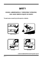
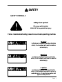
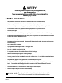
Operator's Manual
3000 SERIES
ZTR® MOWERS
2001
IMPORTANT: READ CAREFULLY
The Dixon® ZTR® Mower is both easy and fun to operate. However,
any power mower must be operated properly to be safe.
It is not a toy or a recreational vehicle.
Before you start to use the mower: read the operator's manual carefully,
and become completely familiar with the controls.
The information in this operator's manual applies to all
Dixon® ZTR® 3000 Series Model Mowers.
Your Dixon dealer will gladly answer any questions.
See your dealer for warranty service, parts and repairs.
DIXON INDUSTRIES, INC.
A BLOUNT International Inc. Co.
PO BOX 1569
COFFEYVILLE KS 67337 0945
316 251 2000
Page 2
INDEX
SAFETY ..................................................................
WARRANTY POLICY............................................
SPECIFICATIONS .................................................
SEAT ADJUSTMENT ............................................
CONTROLS ...........................................................
OPERATION INSTRUCTIONS ...........................
CARE AND MAINTENANCE ...............................
STANDARD PARTS LIST .....................................
TROUBLESHOOTING .........................................
4- 9
10
11 - 13
14
15 - 17
18 - 23
24 - 31
32
33 - 35
3000 Series
Part No. 13086-0700
Page 3
SAFETY
RIDING LAWNMOWERS, IF IMPROPERLY OPERATED,
CAN CAUSE SERIOUS INJURY OR DEATH
The most common causes of injury to the operator or bystander...
BLADE CONTACT
RUN-OVER
TIP-OVER
BACK-OVER
...read and understand this manual to prevent injuries.
Page 4
SAFETY
SAFETY SYMBOLS
Safety Alert Symbol
When you see this symbol,
BE ALERT to the potential for injury.
Follow recommended safety precautions and safe operating practices.
Danger
indicates an imminently hazardous situation
which, if not avoided, will result in death or
serious injury.
Warning
indicates a potentially hazardous situation
which, if not avoided, could result in death or
serious injury.
Caution
indicates a potentially hazardous situation
which, if not avoided, may result in minor or
moderate injury. It may also be used to alert
against unsafe practices.
Page 5
SAFETY
This cutting mower is capable of amputating hands & feet,
and throwing objects.
Failure to observe the following safety instructions could result in
serious injury or death.
GENERAL OPERATION:
•
Read, understand, and follow all instructions in the manual and on the mower before starting.
•
Only allow responsible adults, who are familiar with the instructions, to operate the mower.
•
Clear the area of objects such as rocks, toys, wire, etc., which could be picked up and thrown by the blade.
•
Be sure the area is clear of other people before mowing. Stop mower if anyone enters the area.
•
Never carry passengers.
•
Do not mow in reverse unless absolutely necessary. Always look down and behind before and while backing.
•
Be aware of the mower discharge direction and do not point it at anyone. Do not operate the mower without either
the entire grass catcher or the deflector in place.
•
Slow down before turning.
•
Never leave a running mower unattended. Always turn off blades, set parking brake, stop engine, and remove key
before dismounting.
•
Turn off blades when not mowing.
•
Stop engine before removing grass catcher or unclogging chute.
•
Mow only in daylight or good artificial light.
•
Do not operate the mower while under the influence of alcohol or drugs.
•
Watch for traffic when operating near or crossing roadways.
•
Use extra care when loading or unloading the mower into a trailer or truck. Do not ride the mower when loading &
unloading.
•
Always wear safety goggles or safety glasses with side shields when operating mower.
•
Data indicates that operators, age 60 years and above, are involved in a large percentage of riding mower-related
injuries. These operators should evaluate their ability to operate the riding mower safely enough to protect
themselves and others from serious injury.
•
Follow the manufacturer's recommendation for wheel weights or counterweights.
•
Maintain or replace safety and instruction labels as necessary.
engine exhaust from this product contains chemicals known to the
WARNING: The
State of California to cause cancer, birth defects or other reproductive harm.
Page 6
SAFETY
SLOPE OPERATION:
Slopes are a major factor related to loss-of-control and tip-over accidents,
which can result in severe injury or death.
All slopes require extra caution.
If you cannot back up the slope or if you feel uneasy on it, do not mow it!
DO
Mow across the slope with your Dixon ZTR - never up or down.
Remove obstacles such as rocks, tree limbs, etc.
Watch for holes, ruts or bumps. Uneven terrain could overturn the mower. Tall grass
can hide obstacles.
Use slow speed. Tires may lose traction on slopes even though the brakes are functioning
properly.
Use extra care with grass catchers or other attachments. These can change the stability
of the mower.
Keep all movement on the slopes slow and gradual. Do not make sudden changes in
speed or direction.
Avoid starting or stopping on a slope. If tires lose traction, disengage the blades and
proceed slowly down the slope.
If front wheels lift off the ground, pull the levers back to stabilize the mower.
DO NOT
Do not turn on slopes unless necessary, and then, turn slowly and gradually downhill,
if possible.
Do not mow near drop-offs, ditches, or embankments. The mower could suddenly turn
over if a wheel is over the edge of a cliff or ditch, or if an edge caves in.
Do not mow on wet grass. Reduced traction could cause sliding.
Do not try to stabilize the mower by putting your foot on the ground.
Do not use grass catcher on steep slopes.
Page 7
SAFETY
CHILDREN:
Tragic accidents can occur if the operator is not alert to the
presence of children.
Children are attracted to lawn mowers and the mowing activity.
NEVER assume children will stay where they were last seen.
Be alert to avoid accidents.
• Keep children out of the mowing area and under the watchful care of another responsible
adult.
• Be alert and turn mower off if a child enters the area.
• Before and during backing, look behind and DOWN for small children.
• Never carry children. They may fall off and be seriously injured or interfere with safe
mower operation.
• Never allow children to operate the mower.
• Use extra care when approaching blind corners, shrubs, trees, or other objects that
may obscure vision.
Page 8
SAFETY
SERVICE:
•
Use extra care in handling gasoline and other fuels. They are flammable and vapors are explosive.
Use only an approved container.
Never remove gas cap or add fuel with the engine running. Allow engine to cool before refueling. Do
not smoke.
Never refuel the mower indoors.
Never store the mower or fuel container inside a building where there is an open flame,
If fuel is spilled on clothing, change clothing immediatley.
To prevent fire and explosion caused by static electricity:
Never fill containers inside a vehicle or on a truck or trailer bed with a plastic liner. Always
place containers on the ground away from your vehicle before filling.
When practical, remove gas-powered equipment from the truck or trailer and refuel it on the
ground. If this is not possible, then refuel such equipment on a trailer with a portable
container, rather than from a gasoline dispenser nozzle.
If a gasoline dispenser nozzle must be used, keep the nozzle in contact with the rim of the fuel
tank or container opening at all times until fueling is complete. Do not use a nozzle lock-open
device.
•
Never run a mower inside a closed area. The exhaust fumes are toxic.
•
Keep nuts and bolts tight, especially blade attachment bolts, and keep equipment in good condition.
•
Never tamper with safety devices. Check their proper operation regularly.
•
Keep mower free of grass, leaves, or other debris buildup. Clean up oil or fuel spillage. Allow mower to
cool before storing.
•
Stop and inspect the equipment if you strike an object. Repair, if necessary, before restarting.
•
Never make adjustments or repairs with the engine running.
•
Grass catcher components are subject to wear, damage, and deterioration, which could expose moving
parts or allow objects to be thrown. Frequently check components and replace with original equipment
parts, when necessary.
•
Mower blades are sharp and can cut. Wrap the blade(s) or wear gloves, and use extra caution when
servicing them.
•
Batteries contain sulfuric acid. To prevent burns avoid contact with skin, eyes and clothing. To prevent
a fire or explosion keep sparks and open flames away from battery.
•
Before disconnecting the negative (-) ground cable, make sure all switches are OFF.
•
Check to assure that the drive chains are properly adjusted. A loose chain may come off causing loss of
control.
Page 9
DIXON INDUSTRIES, INC.
a BLOUNT company
AIRPORT INDUSTRIAL PARK
PO BOX 1569
COFFEYVILLE KS 67337 0945
316 251 2000
FAX 316 251 4117
DIXON LIMITED WARRANTY POLICY - 3000 & 4000 SERIES
WARRANTY: Home Owner Application: This Dixon Warranty term is for a period of two (2) years from date of
purchase. Commercial Application: Dixon mowers used for commercial application are warranted for 30 days from the
date of purchase. Commercial use is specified as use other than, or in addition to, mowing at owner's primary place of
residence.
DIXON ZTR MOWERS ARE WARRANTED AGAINST DEFECTS IN MATERIALS
AND WORKMANSHIP AND PROVIDES FOR REPLACEMENT OR REPAIR OF PARTS INCLUDING
LABOR COSTS. THIS WARRANTY IS SUBJECT TO THE FOLLOWING CONDITIONS
AND LIMITATIONS:
1.
Warranty applies only to original retail purchaser of new and unused mowers and accessories.
2.
All Dixon warranty must be accomplished by authorized Dixon dealers and in accordance with Dixon
warranty policy and allowances. All warranty claims must be approved by Dixon Industries, Inc.
3.
Battery warranty: Limited to 90 days from date of purchase.
4.
Accessories Warranty (Grass Catchers, Snow Blades, Covers, etc.): Limited to 90 days from date of purchase.
5
Warranty does not apply to damage in transit or incidents of misuse, negligence, accidents, or alteration. The
use of parts or components other than those supplied by Dixon Industries, Inc. VOIDS ALL WARRANTY.
6.
The following items are not covered by this warranty policy:
(a) Pick up and delivery charges for transportation of mower to and from an Authorized Dixon dealer's place
of business.
(b) Transaxle adjustments.
(c) Belts/chains/sprockets/cutting blades.
(d) Engines -- All engines used on Dixon ZTR mowers are warranted by each individual engine
manufacturer.
(e) Any costs or expense of providing substitute equipment while repair work is being performed on a
warranted mower.
7.
There is no other express warranty. Implied warranties, including those of merchantability and fitness for a
particular purpose, are limited to the same duration of the express warranty, and to the extent permitted by law
any and all implied warranties are excluded. Liabilities for consequential damages under any and all warranties
are excluded.
Blue/Customer
Yellow/Dealer
White/Dixon Ind.
WARRANTY VALIDATION: At the time of sale, selling dealer must review each portion of this warranty document,
complete the information section below, secure customer's signature and send copy to Dixon Industries, Inc.
DATE OF PURCHASE______________________Model _______________S/N__________________________
Owner's Name
Dealership
Address
Address
Owner's Signature
Dealer's Signature
Page 10
SPECIFICATIONS
Model ZTR 3303
CHASSIS:
Twin 12 gauge side frames and 7 gauge transmission and engine base plate.
BODY:
All body parts are made of rotational molded polyethylene. Front body contains
access panel for battery service. Seat tilts forward to allow transmission service.
MOWER DECK:
11 GA stamped steel construction.
Single 30" cut blade.
Cut height approximately 1" to 4" via 7 position lift handle.
BLADE DRIVE:
Mechanical; hand lever engagement.
TRANSMISSION:
Each rear wheel is independently driven by chain and sprockets through a
friction mechanical drive.
ENGINE:
10.5 HP I/C Briggs & Stratton, 4-Cycle, Single Cylinder, Air-Cooled, Gasoline,
Vertical Shaft, Aluminum Head and Block.
STARTING SYSTEM:
Electric by key switch operation with safety interlocks on parking brake and
blade drive.
TIRES:
Front
Rear
11 X 4.00-5 ribbed tread.
16 X 6.50 X 8 Turf Trac R/S tread.
RECOMMENDED
TIRE PRESSURE:
Front
Rear
16-21 PSI
8-14 PSI
CAPACITIES:
Fuel
Engine
2.0 gallons total.
1.25 quarts oil.
DIMENSIONS:
Width
Height
Length
Weight
32.5" outside rear wheel measurement.
32.0" to top edge of seat.
65.5" hitch tab to front bumper.
430 lbs.
NOTE:
Additional information provided in service instructions under the individual
component.
SPECIFICATIONS SUBJECT TO CHANGE WITHOUT NOTICE.
Page 11
SPECIFICATIONS
Model ZTR 3304
CHASSIS:
Twin 12 gauge side frames and 7 gauge transmission and engine base plate.
BODY:
All body parts are made of rotational molded polyethylene. Front body contains
access panel for battery service. Seat tilts forward to allow transmission service.
MOWER DECK:
11 GA stamped steel construction.
Single 30" cut blade.
Cut height approximately 1" to 4" via 7 position lift handle.
BLADE DRIVE:
Mechanical; hand lever engagement.
TRANSMISSION:
Each rear wheel is independently driven by chain and sprockets through a
friction mechanical drive.
ENGINE:
14.5 HP Briggs & Stratton I/C Quiet, 4-Cycle, Single Cylinder, Air-Cooled,
Gasoline, Vertical Shaft, Cast Iron Cylinder, Synchro-Balanced, Laminated
Shroud
STARTING SYSTEM:
Electric by key switch operation with safety interlocks on parking brake and
blade drive.
TIRES:
Front
Rear
11 X 4.00-5 ribbed tread.
16 X 6.50 X 8 Turf Trac R/S tread.
RECOMMENDED
TIRE PRESSURE:
Front
Rear
16-21 PSI
8-14 PSI
CAPACITIES:
Fuel
Engine
2.0 gallons total.
1.25 quarts oil.
DIMENSIONS:
Width
Height
Length
Weight
32.5" outside rear wheel measurement.
32.0" to top edge of seat.
65.5" hitch tab to front bumper.
440 lbs.
NOTE:
Additional information provided in service instructions under the individual
component.
SPECIFICATIONS SUBJECT TO CHANGE WITHOUT NOTICE.
Page 12
SPECIFICATIONS
Model ZTR 3014
CHASSIS:
Twin 12 gauge side frames and 7 gauge transmission and engine base plate.
BODY:
All body parts are made of rotational molded polyethylene. Front body contains
access panel for battery service. Seat tilts forward to allow transmission service.
MOWER DECKS:
36" Deck: 11 GA Laser Cut Fabricated - 36" Cut Width
42" Deck: 13 GA Stamped Steel Construction - 42" Cut Width
Cut height approximately 1" to 4" via 7 position lift handle.
BLADE DRIVE:
Electric clutch.
TRANSMISSION:
Each rear wheel is independently driven by chain and sprockets through a
friction mechanical drive.
ENGINE:
14.5 HP Briggs & Stratton OHV I/C Quiet, 4-Cycle, Single Cylinder, AirCooled, Gasoline, Vertical Shaft, Cast Iron Cylinder, Synchro-Balanced,
Laminated Shroud.
STARTING SYSTEM:
Electric by key switch operation with safety interlocks on parking brake and
blade drive.
TIRES:
Front
Rear
11 X 4.00 -5 ribbed tread.
18 X 8.50 X 8 Multi Trac tread.
RECOMMENDED
TIRE PRESSURE:
Front
Rear
16-21 PSI
8-10 PSI
CAPACITIES:
Fuel
Engine
2.0 gallons total.
1.25 quarts oil.
DIMENSIONS:
Width
Height
Length
Weight
43.0" outside rear wheel measurement.
36.0" to top edge of seat.
65.5" hitch tab to front bumper.
36" Deck: 500 lbs.
42" Deck: 520 lbs.
NOTE:
Additional information provided in service instructions under the individual
component.
SPECIFICATIONS SUBJECT TO CHANGE WITHOUT NOTICE.
Page 13
SEAT ADJUSTMENT
INSTRUCTIONS
Models ZTR 3303 - ZTR 3304 - ZTR 3014
1.
Raise and push seat assembly forward.
2.
Loosen five nuts, P/N 3205, and slide seat forward or backward to desired
position.
3.
Re-tighten nuts, P/N 3205. DO NOT operate mower without seat adjustments
properly tightened.
4.
Push seat assembly back to closed position.
Page 14
CONTROLS
The Dixon ZTR has a unique transaxle that requires only two drive levers to control
braking, turning, speed, and direction.
On initial operation, set throttle speed on slow. Operate with mower blade "OFF".
To avoid "over-controlling" the mower, use a light touch on the drive levers.
Slight movements using fingertip control is all that is necessary.
PARKING BRAKE:
The parking brake is designed to hold the mower from moving and is
not intended for use in stopping the mower while it is in motion.
CAUTION
Engage parking brake before starting engine.
TO SET PARKING BRAKE:
The hand operated parking brake is located on the right end of the
mower.
To engage brake, pull lever up (to the rear).
To release brake, move lever forward (down).
NOTE:
Always set parking brake before dismounting.
Release parking brake before moving mower.
TRANSMISSION DRIVE SYSTEM:
Allows the mower to turn on its own axis
"Zero Turning Radius"
Each lever controls one side of the mower.
NOTE:
The pressure required to operate the mower is very light.
Page 15
CONTROLS
(Left turn opposite)
TO GO FORWARD:
From neutral position, gently push both drive levers forward.
To increase speed, move levers farther forward.
TO GO BACKWARD:
From neutral position, gently pull both drive levers toward you.
TURNING:
Turning is controlled by moving one drive lever slightly forward or rearward of the other.
To turn left, move left lever rearward of the right lever.
To turn "square corners" move lever of desired direction to neutral.
To turn on mower's own axis (zero turning radius) stop and move one lever to reverse
position and the other to forward position.
BRAKING:
To brake mower, move both levers in direction opposite of travel, release levers to neutral,
set parking brake. Park only on level surfaces.
THROTTLE CONTROL LEVER:
Located on control panel to operators right.
Throttle control for engine speed.
Choke for engine starting.
Throttle Control should be set to the MAXIMUM or wide open setting to insure adequate
cooling of the engine and to maintain mower deck blade speed while mowing.
Page 16
CONTROLS
BLADE DRIVE:
Models ZTR 3303 & 3304
Located to left of operator.
To engage the mower blade, turn lever on floor
slowly to the "ON" position.
To disengage mower blade, turn lever to the
"OFF" position.
BLADE DRIVE:
Model ZTR 3014
Located on control panel, on operator's right.
To engage the mower blades, pull up on the
switch.
To disengage blades, push down.
CIRCUIT BREAKER:
Protection of the electrical system is by
(1) 15 amp circuit breaker.
If circuit breaker trips, push button to reset.
If this condition repeats, consult dealer for inspection
and repair.
MOWER DECK CUT HEIGHT LIFT LEVER:
Located to left of operator.
Controls the cutting height.
Seven positions of adjustment.
Move lever in and forward to lower.
Move lever in and back to raise.
NOTE: Always use high for transport.
Page 17
OPERATION INSTRUCTIONS
Safe and successful operation will depend upon the operator having the correct knowledge of all controls
used on the mower and making good judgements about the terrain to be mowed.
NEVER allow anyone to operate the mower without complete knowledge of all controls and their functions.
During initial operation, "learning to drive", set throttle at slow speed.
Sound judgement by the operator will prevent accidents.
TOWING
Towing a trailer or other attachment that is too heavy could damage the drive or cause the mower to
become unstable. Limit loads to 250 pounds or less on this mower.
BEFORE OPERATING MOWER:
1. Read engine manufacturer's operating and maintenance instructions.
2. Discuss proper maintenance with your dealer.
3. Read and observe all safety instructions on your mower and in the manual.
4. Check engine oil.
5. Be sure gas cap is in place.
6. Be sure parking brake is on.
7. Be sure mower blade drive is off.
8. Know how to stop engine. (Turn key to off position)
Page 18
OPERATION INSTRUCTIONS
TESTING OF SAFETY INTERLOCK SYSTEMS:
PARKING BRAKE SWITCH TEST:
a)Place Parking Brake in OFF position
b)Turn ignition switch to START
Engine should not turn over or attempt to start.
BLADE DRIVE SWITCH TEST:
a)Place Parking Brake in ON position
b)Engage blade drive switch
c)Turn ignition switch to START
Engine should not turn over or attempt to start.
SEAT SWITCH TEST:
a)In a SAFE AREA away from bystanders, start the engine
b)Engage blade drive switch
c) Raise slightly off seat
Engine should stop!
If Any Safety Check FAILS: Do Not Operate The Mower until
the system has been checked and repaired
by an Authorized Dixon ZTR Dealer!
Page 19
OPERATION INSTRUCTIONS
STARTING INSTRUCTIONS:
1. Parking brake must be on, and blade drive disengaged.
2. Move throttle control to "Choke" position if engine is cold, full throttle
if warm.
3. Insert ignition key and turn to "Start" position. When engine starts,
release ignition key. Key will return to "Run" position.
4. Move throttle from "Choke" to desired speed position.
5. Release parking brake.
6. Operate the mower per the "CONTROL" instructions on Page 16.
NOTE: While mowing, "blade(s) engaged", throttle control must be
set to the MAXIMUM or wide open setting to insure adequate
cooling of the engine and to maintain mower deck blade
speed.
36" - 42"
Page 20
30"
OPERATION INSTRUCTIONS
MOWING WITH A MULCHING ATTACHMENT:
Mulching or recycling the grass clippings requires a totally different mowing approach than would be normal
when side discharging or bagging the grass. There may be instances or conditions where it is not possible
to hide all of the recycled or mulched clippings.
In order to achieve the best results, please read and follow the mulching tips listed below:
1.
Set the engine speed control to the wide open or full setting.
2.
Place the mower deck cut height selector in either the top or second notch. Never cut more than
3/4" to 1" off the grass at any one time. Attempting to cut more grass will result in the deck
plugging and cause the engine to stall.
3.
It may be necessary to cut the lawn twice to achieve acceptable mulching performance especially
on first cuttings or if the lawn is heavily fertilized.
4.
Do Not Attempt To Cut Grass When It Is Wet. Mulching performance will be very poor under
wet grass conditions.
5.
Maintain Sharp Blade(s) Throughout The Cutting Season. This is very important. Optimal
mulching performance cannot be obtained with a dull or nicked up blade.
6.
Keep The Underside Of The Mower Deck Clean. Remove all grass and dirt buildup from the
underside of the pan, the baffles and deflectors after each use.
7.
Alternate mower direction. This will evenly disperse the mulched grass clippings over the lawn
for even fertilization.
If the mulching quality of the mower does not seem to be satisfactory, try one or more of the
following tips:
1.
Raise the height-of-cut setting on your mower.
2.
It may be necessary to cut your grass more frequently.
3.
Operate the mower at a slower ground speed.
4.
Overlap cutting swaths instead of cutting a full swath with each pass.
5.
Mow across the marginal areas a second time.
6.
CUT HIGH - MOW OFTEN!
Page 21
OPERATION INSTRUCTIONS
MOWING WITH A GRASS CATCHER ATTACHMENT:
In order to achieve optimum performance when mowing with a grass catching attachment, please read and
follow the tips listed below.
1.
Set engine speed control to the wide open or full setting.
2.
Do Not Attempt To Cut Grass When It Is Wet. Wet grass will clog both the underside of the deck and
the attachment chutes. Empty bags often to prevent plugging.
3.
If the grass is tall, place the mower deck cut height selector in the top or second notch. "Initially" overlap
cutting swaths instead of a full swath with each pass.
4.
Keep The Underside Of The Mower Deck Clean. Frequent removal of dried grass and dirt will greatly
assist in bagging of the clippings.
5.
Use only the correct blade(s). Some grass catching attachments require a "high-lift" blade. See your
dealer for advice on the type of blade(s) needed for your mower.
6.
Maintain Sharp Blade(s) Throughout The Cutting Season.
7.
Operate the mower at a slower ground speed than when mowing without a grass catching attachment.
8.
Some mowing applications/use of grass catchers may require that an optional weight box be fitted to
the mower to counter the weight of grass in the bags. Please consult with your dealer for more
information regarding installation and adding weight to the box.
CAUTION
•
Watch for low hanging branches or other obstacles which might hit the catcher top while turning or
backing the mower.
•
Use care when backing to avoid pushing the grass bags into the frame or "hot" exhaust muffler of the
engine.
•
Disengage blade and stop engine prior to clearing grass from either the discharge chute or grass catcher
components.
•
Keep all attachment bolts tight.
•
Do Not operate the mower with the grass catching attachment partially removed.
•
Important:
• Do not leave clippings in the bags while the mower is stored.
• Damp grass clippings are a fire hazard if left in the bags.
Page 22
OPERATION INSTRUCTIONS
SIDE DISCHARGE OF THE CLIPPINGS:
In order to achieve optimum performance when side discharging the grass clippings, please read and
follow the tips listed below.
Additional information can be found in the troubleshooting guide.
CAUTION
Be sure that deflector is properly installed on the
discharge chute.
1. Set engine speed control to the wide open or full setting.
2. Do Not Attempt To Cut Grass When It Is Wet. Wet grass will clog the underside of the deck and
discharge area.
3. If the grass is tall, place the mower deck cut height lever in the top or second notch. "Initially"
overlap cutting swaths instead of a full swath with each pass. Some applications may require a
second cutting.
4. Keep The Underside Of The Mower Deck Clean. Frequent removal of dried grass and dirt will allow
the clippings to discharge correctly.
5. Maintain Sharp Blade(s) Throughout The Cutting Season.
GRASS HEIGHT SUGGESTIONS:
Correct mowing height can reduce weeds and disease by 50 to 80%
The following grass cut heights are based on adequate moisture conditions and normal thatch buildup
in a healthy lawn. Some locations and applications may require slightly different cut heights. If in
doubt, consult your local lawn professional for assistance.
Grass Types:
Zoysia
Blue Grass
Fescue Blends
St. Augustine (Mid South)
St. Augustine (Deep South)
Tifton Bermuda
Centipede
Common Bermuda
Bahia/Argentina/Pensacola
Best Cut Heights
2" - 2 1/2"
1 1/2" - 3"
1 1/2" - 3"
1 1/2" - 2"
3" - 4"
1 1/2"
1 1/2" - 2"
1 1/2" - 2"
2"
Page 23
CARE AND MAINTENANCE
This portion of the owners manual deals with normal service items which can be performed by the owner.
Please remember that if you are in doubt as to the correct service procedures to be followed, these and other
service situations can be handled by a Dixon ZTR dealer who is familiar with the service of your mower.
MAINTENANCE SCHEDULE:
To insure a long and trouble free service life of all components used on the, a regular and
thorough maintenance schedule should be followed. The following items should be checked
after the first (10) hours of operation and on a weekly basis, or each (40) hours of use:
1.
2.
3.
4.
5.
6.
7.
Drive Chain
Drive system, belts and controls.
Mower deck belts.
Tire pressures.
Tightness of all nuts and bolts.
Battery fluid level.
Engine Oil.
CAUTION
Before performing any maintenance,
shut off engine, allow to cool.
ENGINE:
For engine operating and maintenance information, refer to the engine operating and
maintenance instructions furnished by the engine manufacturer, supplied with each
mower.
BATTERY:
Check the fluid in the battery at frequent intervals.
Keep fluid level above the plates in each cell, using distilled water.
OFF-SEASON BATTERY STORAGE:
Identify each cable so cables can be reconnected to correct terminals.
Disconnect cables from terminals
ALWAYS disconnect ground cable first and reconnect last
Charge battery.
DO NOT remove battery from mower.
Clean top of battery and terminals with baking soda and water.
Page 24
CARE AND MAINTENANCE
CUTTER BLADE MAINTENANCE:
NOTE: Observe proper blade position prior to removal.
1. Safely raise front of mower.
2. Hold or block blade from turning.
3. Loosen blade nut and remove blade.
4. When replacing blade, tighten blade nut securely. Refer to diagram.
CAUTION
Wear heavy, thick gloves when holding onto cutter blade, avoid the
sharp edge of the blade.
NOTE: Be sure blade is centered on pilot before tightening nut to 60 ft. lbs.
torque.
(No trash guard on 30" machines.)
Page 25
CARE AND MAINTENANCE
BELT TENSION:
Model ZTR 3303 & 3304: Manual Clutch-- No Adjustment
Model ZTR 3014-42" Deck: Belt tension maintained via spring loaded idler pulley.
Model ZTR 3014-36"Deck: Electric Clutch--Adjust idler shock mount per diagram.
DECK REMOVAL-MANUAL CLUTCH-MODELS 3303 & 3304:
1. Place cut height lever in lowest cut position.
2. Loosen belt keepers.
3. Remove deck drive belt from engine pulley.
4. Using a slight upward twisting motion, remove link from engagement handle.
5. Turn handle fully to the left until handle clears stop on mower deck pan. Lift and
remove handle through hole in lower body.
6. Remove hair pin cotter and washer from one end of deck support cross shaft. Note
location of remaining shim washers used between chassis and mower deck pan
arms. Slide shaft from chassis and mower deck.
7. Remove hair pin cotter and washer from each deck adjustment rod. Carefully push
each link toward the inside of the mower chassis. At this point, deck will drop
down.
8. Carefully raise and support front of chassis. Slide mower deck to either side for
removal. (Reverse procedure to reinstall deck assembly).
Page 26
CARE AND MAINTENANCE
DECK REMOVAL - ELECTRIC CLUTCH
MODEL ZTR 3014
1. Place cut height lever in lowest cut position.
2. For 36" decks, loosen nut on belt idler shock mount until belt can be removed from
electric clutch pulley on the bottom of the engine. Refer to illustration below.
For 42" decks, pull belt idler back to allow belt to be removed from idler pulley and
electric clutch pulley.
3. Remove hair pin cotter and washer from one end of deck support cross shaft. Note
location of remaining shim washers used between chassis and mower deck pan
arms. Slide shaft from chassis and mower deck.
4. Remove hair pin cotter and washer from each deck adjustment rod. Carefully push
each link toward the inside of the mower chassis. At this point, deck will drop
down.
5. Carefully raise and support front of chassis. Slide mower deck to either side for
removal. (Reverse procedure to reinstall deck assembly).
Page 27
CARE AND MAINTENANCE
FUEL SHUT OFF VALVE:
The fuel shut off valve is located at the bottom rear of the fuel tank.
Always turn the valve to the "OFF" position when the mower is stored or not in use.
LUBRICATION:
CHASSIS:
Number of grease zerks used: (5) for 30"
(6) for 36"
(7) for 42"
LOCATIONS:
(1) each front wheel caster and each front wheel hub.
(1) each mower deck hub
SERVICE INTERVALS:
Every 50 hours of operation.
RECOMMENDED GREASE:
Name brand wheel bearing or multi-purpose grease.
Once per season or 50 hours of operation (3 pumps each).
Page 28
CARE AND MAINTENANCE
HOT oil may cause burns.
Allow engine to cool before draining oil.
CAUTION
CHANGING THE ENGINE OIL:
1. The "Dapco" oil drain valve is located on the left side of the engine crankcase.
2. Place a suitable container under the drain valve. The fitting of a short piece of hose
will help direct the oil.
3. To drain turn hex head valve stem counter clockwise with 10mm wrench or socket.
Open to full open (approximately 7 turns).
4. After engine is drained tighten hex stem.
NOTE:
Refer to engine manufacturer's recommendations for frequency of oil
changes.
Hex Head Valve Stem
OIL FILL:
1. Drain oil.
2. Clean any spilled oil from engine and chassis.
3. Refill engine with type, and quantity of oil recommended by the engine
manufacturer in engine literature.
PLEASE DISPOSE OF USED OILS AT PROPER COLLECTION CENTERS.
PROTECT YOUR ENVIRONMENT
Page 29
CARE AND MAINTENANCE
DRIVE SYSTEM ADJUSTMENTS:
Due to both the complex nature of the transmission and the number of special
tools required for service, adjustments should be entrusted to your dealer.
There are a number of simple owner service items which greatly influence the
performance of the drive system.
1.
Front and rear tires must be inflated to proper specifications.
2.
Rear drive chain tension.
3.
Tightness of all controls and linkages pertaining to the drive levers.
4.
Lubrication of both primary and final drive chains. The use of a high quality chain
lubricant is highly recommended.
REAR CHAIN ADJUSTMENT:
Proper tension for the rear drive chains is accomplished through the use of an "automatic" adjuster located at
mid-point of each rear chain.
Maintenance:
Periodically remove any build up of grass, mud or other debris from both the spring loaded roller and
the upper guide rod. The use of a penetrating lubricant on the springs and rod is recommended as a
rust preventative.
Page 30
CARE AND MAINTENANCE
WHEELS AND TIRES:
Correct tire pressure is important for correct operation of mower.
Models ZTR 3303-ZTR 3304
Front Tires
Rear Tires
11 X 4.00-5
16 X 650 X 8
16-21 PSI
8-14 PSI
Model ZTR 3014
Front Tires
Rear Tires
11 X 4.00-5
18 X 850 X 8
16-21 PSI
8-14 PSI
NOTE: Check lug nuts periodically for tightness.
ELECTRICAL SYSTEMS:
Keep all connections clean and tight.
CLEANING THE MOWER:
Wash mower periodically.
Clean above and below deck.
NOTE:
Allow mower to cool before washing. If bearings
are hot, they will draw moisture inside as they dry
and cause corrosion.
MOWER DECK PLATES:
Check periodically. Replace bolted-on wear plates before
shaft wears into mower deck plates. See illustration.
SERIAL NUMBERS:
The serial number is located on frame at rear of engine, it will
begin with DM.
WARRANTY:
Refer to Warranty Registration Form (P/N 8288).
PARTS/SERVICE:
See your Dixon dealer for replacement parts, warranty or
service.
PLEASE HELP PROTECT THE ENVIRONMENT BY AVOIDING ALL
CHEMICALS WHICH MAY DAMAGE OR CAUSE HARM TO PLANTS AND
ANIMALS IN YOUR AREA.
Page 31
STANDARD SERVICE PARTS LIST
MODELS ZTR 3303 & ZTR 3304
BLADES:
Standard:
Hi-Lift:
P/N 2483
P/N 2484
BELTS:
Engine To Mower Deck:
Engine To Transmission:
P/N 7725
P/N 7650
MODEL ZTR 3014
36" Deck
42" Deck
Standard
P/N 1324 Lo-lift
P/N 1351 Hi-lift(R)
P/N 1352 Hi-lift(L)
P/N 8688 Hi-lift
P/N 6236 Lo-lift
Engine To Mower Deck:
Engine To Transmission:
Serpentine Blade Drive Belt:
P/N 7835
P/N 7650
P/N 7725
P/N 7650
P/N 6109
BLADES:
BELTS:
BRIGGS & STRATTON AIR/OIL FILTER PART NUMBERS:
Please refer to Briggs & Stratton Engine Operator's Manual for correct service intervals for engine oil
changes and air filter maintenance.
Protect your engine investment, use only original equipment filters.
Model ZTR 3303:
10.5HP
Air Filter & Pre-Cleaner Kit: P/N 79001
Oil Filter:
P/N 79006
Model ZTR 3304:
14.5HP
Air Filter & Pre-Cleaner Kit: P/N 79002
Oil Filter:
P/N 79006
Model ZTR 3014:
14.5HP
Air Filter & Pre-Cleaner Kit: P/N 79002
Oil Filter:
P/N 79006
Page 32
TROUBLESHOOTING
MOWER CUT QUALITY:
There are many variables that can effect the cut quality of any riding mower. Type and conditions of grass,
cut height setting, engine RPM and ground speed are some of the variables that interact creating differences
in cut quality. Examination of one or more of the above will generally produce a quality cut.
The Troubleshooting Chart suggests practices and adjustments that may be helpful in improving cut quality.
Your Dixon ZTR dealer is also available to provide assistance to you.
SITUATION
CAUSES
REMEDY
Poor cut quality
Ground speed
Reduce mowing speed
Poor cut quality
Loose engine to
mower deck belt
Refer to Page 26
Poor cut quality
Engine RPM too low
Increase engine RPM to maximum
Poor cut quality
Dull or bent blade
Sharpen or replace as required
Poor cut quality
Un-level mower deck
Consult your dealer
Poor cut quality
Grass buildup under
mower deck
Clean out underside of mower deck
Poor cut quality
Improper blades
Replace with original equipment
blade designed for the 3000 Series
Models
Poor cut quality
Uneven tire pressures
Check and adjust as required per
operator's manual
Page 33
TROUBLESHOOTING
DRIVE SYSTEM:
SITUATION
CAUSES
REMEDY
Mower pulls to one
side or the other
Drive adjustment
Consult your dealer for repair
Poor driving
performance
Operation of mower
Review operator's section
of owner's manual
Page 34
TROUBLESHOOTING
ELECTRICAL SYSTEM:
SITUATION
CAUSES
REMEDY
Starter will not
turn engine over
Circuit breaker engaged
Push button to reset
Consult your dealer for repair
Starter will not
turn engine over
Dead battery
Charge battery
Battery discharge
Poor connections on
battery
Battery water low
Wrong battery installed
in mower
Tighten or replace as required
Battery discharge
Engine electrical system
not functioning correctly
Have electrical system checked by
your dealer
Battery discharge
Engine being operated
at too low an RPM
Increase engine RPM
Contact your dealer for information
NOTE:
Electrical system failures are generally simple in nature, always check the obvious first and then
move onto the more complicated parts used. Poor battery service, loose connections, corrosion,
frayed or broken wiring, are more likely than component failure.
Page 35
NOTES
Page 36
NOTES
Page 37
NOTES
Page 38
OWNER
INFORMATION
DIXON INDUSTRIES, INC.
A BLOUNT International Inc. Co.
PO BOX 1569
COFFEYVILLE KS 67337 0945
316 251 2000
FAX 316 251 4117
DATE PURCHASED
MOWER MODEL NUMBER
MOWER SERIAL NUMBER
DM-
PURCHASED FROM
Name
Address
DATE OIL CHANGED:
DATE ENGINE TUNED:
engine exhaust from this product contains chemicals known to the State of California
WARNING: The
to cause cancer, birth defects or other reproductive harm.
Dixon® and ZTR® are registered trademarks of Dixon Industries, Inc.
DIXON INDUSTRIES, INC.
A BLOUNT International Inc. Co.
PO BOX 1569
COFFEYVILLE KS 67337 0945
316 251 2000
3000 Series
3303-3304-3014
Part No. 13086-0700