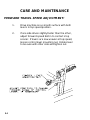
1
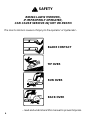
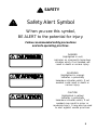
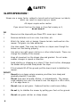
OPERATOR’S MANUAL
5000 SERIES
ZTR®
2002
IMPORTANT - READ CAREFULLY
The Dixon® ZTR® Mower is both easy and fun to operate.
However, any power mower must be operated properly to be
safe. It is not a toy or a recreational vehicle. Before you
start to use the mower, read the operator’s manual carefully
and become completely familiar with the controls.
The information contained in this manual applies to all
Dixon® ZTR® 5000 Series Mowers. Your Dixon dealer
will gladly answer any questions.
See your dealer for warranty service, parts and repairs.
INDEX
Page
Safety. . . . . . . . . . . . . . . . . . . . . . . . . . . . . . . . . . . . . 4-11
Warranty Policy. . . . . . . . . . . . . . . . . . . . . . . . . . . . . . .12
Specifications. . . . . . . . . . . . . . . . . . . . . . . . . . . . . . . . .13-14
Seat Adjustment Instructions. . . . . . . . . . . . . . . . . . . . . . . . .15
Controls. . . . . . . . . . . . . . . . . . . . . . . . . . . . . . . . . .16-20
Operation Instructions. . . . . . . . . . . . . . . . . . . 21-32
Care & Maintenance. . . . . . . . . . . . . . . . . . . . . .33-54
Standard Service Parts List. . . . . . . . . . . . . . . . . . . .55
Troubleshooting. . . . . . . . . . . . . . . . . . . . . . . . . . 56-57
5000 Series
Part No. 13089-0601
3
SAFETY
RIDING LAWN MOWERS,
IF IMPROPERLY OPERATED,
CAN CAUSE SERIOUS INJURY OR DEATH.
The most common causes of injury to the operator or bystander...
BLADE CONTACT
TIP OVER
RUN OVER
BACK OVER
...read and understand this manual to prevent injuries.
4
SAFETY
Safety Alert Symbol
When you see this symbol,
BE ALERT to the potential for injury.
Follow recommended safety precautions
and safe operating practices.
DANGER
(highlighted in red)
indicates an imminently hazardous
situation which, if not avoided, will
result in death or serious injury.
WARNING
(highlighted in orange)
indicates a potentially
hazardous situation which, if not
avoided, could result in death or
serious injury.
CAUTION
(highlighted in yellow)
indicates a potentially
hazardous situation which, if not
avoided, may result in minor or
moderate injury. It may also be used
to alert against unsafe practices.
5
SAFETY
Failure to observe the following safety
instructions could result in serious injury or death.
GENERAL OPERATION:
•Read, understand, and follow all instructions in the manual
and on the mower before starting.
•Only allow responsible adults, who are familiar with the
instructions, to operate the mower.
•Clear the area of objects such as rocks, toys, wire, etc.,
which could be picked up and thrown by the blade.
•Be sure the area is clear of other people before mowing.
Stop mower if anyone enters the area.
•NEVER carry passengers.
•Do not mow in reverse unless absolutely necessary. Always
look down and behind before and while backing.
•Be aware of the mower discharge direction and do not point
it at anyone.
•Do not operate the mower without either the entire grass
catcher or the deflector in place.
•Slow down before turning.
•Never leave a running mower unattended. Always turn off
blades, set parking brake, stop engine and remove key before
dismounting.
6
SAFETY
GENERAL OPERATION (continued):
•Turn off blades when not mowing.
•Stop engine before removing grass catcher or unclogging
chute.
•Mow only in daylight or good artificial light.
•Do not operate the mower while under the influence of
alcohol or drugs.
•Watch for traffic when operating near or crossingroadways.
•Use extra care when loading or unloading the mower into a
trailer or truck. Do not ride the mower when loading and
unloading.
•Always wear safety goggles or safety glasses with side
shields when operating mower.
•Data indicates that operators, age 60 years and above, are
involved in a large percentage of riding mower-related
injuries. These operators should evaluate their ability to
operate the riding mower safely enough to protect
themselves and others from serious injury.
•Follow the manufacturer’s recommendation for wheel
weights and counterweights.
•Maintain or replace safety & instruction labels as needed.
WARNING:
The engine exhaust from this product contains chemicals known to the
State of California to cause cancer, birth defects or other reproductive
harm.
7
SAFETY
SLOPE OPERATION:
Slopes are a major factor related to loss-of-control and tip-over accidents,
which can result in severe injury or death.
All slopes require extra caution.
If you cannot back up the slope or if you feel uneasy on it,
do not mow it!
DO
•
Mow across the slope with your Dixon ZTR - never up or down.
•
Remove obstacles such as rocks, tree limbs, etc.
•
Watch for holes, ruts or bumps. Uneven terrain could overturn the
mower. Tall grass can hide obstacles.
•
Use slow speed. Tires may lose traction on slopes even though the
brakes are functioning properly.
•
Use extra care with grass catchers or other attachments. These can
change the stability of the mower.
•
Keep all movement on the slopes slow and gradual. Do not make
sudden changes in speed or direction.
•
Avoid starting or stopping on a slope. If tires lose traction, disengage
the blades and proceed slowly down the slope.
•
If front wheels lift off the ground, pull the levers back to stabilize the
mower.
DO NOT
•
Do not turn on slopes unless necessary, and then, turn slowly and
gradually downhill, if possible.
•
Do not mow near drop-offs, ditches, or embankments. The mower
could suddenly turn over if a wheel is over the edge of a cliff or ditch,
or if an edge caves in.
•
Do not mow on wet grass. Reduced traction could cause sliding.
•
Do not try to stabilize the mower by putting your foot on the ground.
•
Do not use grass catcher on steep slopes.
8
SAFETY
CHILDREN:
Tragic accidents can occur if the operator is
not alert to the presence of children.
Children are attracted to lawn mowers and the mowing activity.
NEVER assume children will stay where they were last seen.
Be alert to avoid accidents.
•
Keep children out of the mowing area and under the
watchful care of another responsible adult.
•
Be alert and turn mower off if a child enters the area.
•
Before and during backing, look BEHIND and DOWN for
small children.
•
Never carry children. They may fall off and be seriously
injured or interfere with safe mower operation.
•
Never allow children to operate the mower.
•
Use extra care when approaching blind corners, shrubs,
trees, or other objects that may obscure vision.
9
SAFETY
SERVICE:
•
Use extra care in handling gasoline and other fuels. They are
flammable and vapors are explosive.
Use only an approved container.
Never remove fuel cap or add fuel with engine running.
Allow engine to cool before refueling.
Do not smoke while refueling.
Never refuel the mower indoors.
Never store the mower or fuel container inside a building
where there is an open flame.
If fuel is spilled on clothing, change clothing immediately.
To prevent fire and explosion caused by static electricity:
Never fill containers inside a vehicle or on a truck
or trailer bed with a plastic liner. Always place
containers on the ground away from your vehicle
before filling.
When practical, remove fuel-powered equipment
from the truck or trailer and refuel it on the
ground. If this is not possible, then refuel such
equipment on a trailer with a portable container,
rather than from a fuel dispenser nozzle.
If a fuel dispenser nozzle must be used, keep the
nozzle in contact with the rim of the fuel tank or
container opening at all times until fueling is
complete. Do not use a nozzle lock-open device.
10
SAFETY
SERVICE (continued):
•
Never run a mower inside a closed area. The exhaust fumes are
toxic.
•
Keep nuts and bolts tight, especially blade attachment bolts, and
keep equipment in good condition.
•
Never tamper with safety devices. Check their proper operation
regularly.
•
Keep mower free of grass, leaves, or other debris buildup. Clean
up oil or fuel spillage. Allow mower to cool before storing.
•
Stop and inspect the equipment if you strike an object. Repair,
if necessary, before restarting.
•
Never make adjustments or repairs with the engine running
unless otherwise specified.
•
Grass catcher components are subject to wear, damage and
deterioration, which could expose moving parts or allow objects
to be thrown. Frequently check components and replace with
original equipment parts, when necessary.
•
Mower blades are sharp and can cut. Wrap the blade(s) or wear
gloves, and use extra caution when servicing them.
•
Batteries contain sulfuric acid. To prevent burns avoid contact
with skin, eyes and clothing. To prevent a fire or explosion keep
sparks and open flames away from battery.
•
Before disconnecting the negative (-) ground cable, make sure all
switches are OFF.
11
DIXON INDUSTRIES, INC.
a BLOUNT company
Airport Industrial Park
P.O. Box 1569
Coffeyville, Ks 67337- 0945
620-251-2000
Fax 620-251-4117
DIXON LIMITED WARRANTY POLICY - ESTATE MODELS
5000 Series
WARRANTY: Home Owner Application: This Dixon Warranty term is for
from date of purchase. Commercial Application: Dixon mowers used for
are warranted for one (1) year from the date of purchase or 400 hours
Commercial use is specified as use other than, or in addition to, mowing
place of residence.
a period of two (2)years
commercial application
whichever comes first.
at owner’s primary
DIXON ZTR MOWERS ARE WARRANTED AGAINST DEFECTS IN MATERIALS
AND WORKMANSHIP AND PROVIDES FOR REPLACEMENT OR REPAIR
OF PARTS INCLUDING LABOR COSTS. THIS WARRANTY IS SUBJECT
TO THE FOLLOWING CONDITIONS AND LIMITATIONS:
1. Warranty applies only to original retail purchaser of new & unused mowers and accessories.
2. All Dixon warranty must be accomplished by authorized Dixon dealers and in accordance with Dixon
warranty policy and allowances. All warranty claims must be approved by Dixon Industries, Inc.
3. Battery warranty: Limited to 90 days from date of purchase.
4. Accessories Warranty (Grass Catchers, Snow Blades, Covers, etc.): Limited to 90 days from date of
purchase.
5. Warranty does not apply to damage in transit or incidents of misuse, negligence, accidents, or
alteration. The use of parts or components other than those supplied by Dixon Industries,
Inc. VOIDS ALL WARRANTY.
6. The following items are not covered by this warranty policy:
a.
Pick up and delivery charges for transportation of mower to and from an authorized Dixon
dealer’s place of business.
b.
Routine maintenance or adjustments.
c.
Belts/cutting blades/Hydro-Gear filters.
d.
Engines - All engines used on Dixon ZTR mowers are warranted by the individual engine
manufacturer.
e.
Any costs or expense of providing substitute equipment while repair work is being
performed on a warranted mower.
7. There is no other express warranty. Implied warranties, including those of merchantability and fitness
for a particular purpose, are limited to the same duration of the express warranty, and to
the extent permitted by law any and all implied warranties are excluded. Liabilities for
consequential damages under any and all warranties are excluded.
Blue/Customer
Yellow/Dealer
White/Dixon Ind.
WARRANTY VALIDATION: At the time of sale, selling dealer must review each portion of this
warranty document, complete the information section below, secure customer’s signature and
send copy to Dixon Industries, Inc.
DATE OF PURCHASE____________________MODEL___________________S/N_______________
_____________________________________
______________________________________
Owner’s Name
Dealership
_____________________________________
______________________________________
Address
Address
______________________________________
_______________________________________
_____________________________
______________________________
Owner’s Signature
Dealer’s Signature
12
SPECIFICATIONS
Model ZTR 5020
CHASSIS:
11 GA - rectangular tube
BODY:
Two piece-made of rotational molded polyethylene. Front
body contains access panels for battery service & engine
to mower deck belt removal. Rear body tilts up to allow
service on the entire drive system.
SEAT:
Designed for operator comfort by use of high-density
closed cell foam padded back rest and arm rests,
upholstered with CorduraTM water-repellent fabric. Seat
is adjustable fore and aft.
MOWER DECK:
Two decks are available. The 60” is made of stamped
steel. The 50” is made of 11 GA fabricated welded
construction with external reinforcement ribs. Three
blades combine for either a 50” or 60” cut width. Cut
height approximately 1.5” to 4.5” via 7 position lift handle.
BLADE DRIVE:
Electric clutch
DRIVE SYSTEM:
Each rear wheel is independently driven by a HydroGear
BDU-10L Series 70 hydrostatic transmission. The hydrostatic
transmissions power a fully enclosed HydroGear gearbox.
ENGINE:
20HP Briggs & Stratton ELS, overhead valves, replaceable
oil filter, full pressure lube system, dual element air cleaner,
integral fuel pump.
STARTING SYSTEM: Electric by key switch operation with safety interlocks on
parking brake and blade drive clutch.
TIRES:
Front
Rear
11 X 4-5 ribbed tread
20 X 10-8 Multi-Trac
RECOMMENDED
TIRE PRESSURE:
Front
Rear
16 - 21 lbs.
8 - 14 lbs.
CAPACITIES:
Fuel - 4.8 gallons total (dual tanks)
Oil tank - 3 quart with in-line 40 micron filter
Engine - 2 qts. SAE 30 (with filter)
DIMENSIONS:
Width
Height
Length
Weight
60” (50” Deck), 73” (60” Deck)
45”
72:
668 lbs, (50” Deck, 685 lbs (60” Deck)
Additional information provided in service instructions under the individual component.
SPECIFICATIONS SUBJECT TO CHANGE WITHOUT NOTICE
13
SPECIFICATIONS
Model ZTR 5023
CHASSIS:
11 GA - rectangular tube
BODY:
Two piece - made of high-density polyethylene. Front body contains
access panels for battery service and engine to mower deck belt
removal. Rear body tilts up to allow service on the entire drive
system.
SEAT:
Designed for operator comfort by use of high density closed cell
foam padded back and arm rests, upholstered with CorduraTM
water-repellent fabric. Seat is adjustable fore and aft.
MOWER DECK:
Two decks are available. The 60" is made of stamped steel. The
50" is made of 11 GA fabricated welded construction with external
reinforcement ribs. Three blades combine for a 50" or 60" cut
width. Cut height approximately 1.5" to 4.5" via 7 position lift
handle.
BLADE DRIVE:
Electric clutch
DRIVE SYSTEM:
Each rear wheel is independently driven by a HydroGear BDU-10L
Series 70 hydrostatic transmission.The hydrostatic
transmissions, in turn, power a fully enclosed HydroGear gearbox.
ENGINE:
23HP Kohler Command, 4-Cycle, V-Configuration, Overhead Valve,
Air-Cooled, Gasoline, Vertical Shaft, Aluminum Head, and Crankcase
with Cast Iron Liners, Full Pressure Lubrication/Full Flow Filter,
Pulse-type Fuel Pump, Fixed Jet Carburetor w/Smart-Choke,
Electronic Ignition, In-Line Fuel Filter, Dual Element Air Cleaner.
STARTING SYSTEM:
Electric by key switch operation with safety interlocks on parking
brake and blade drive clutch.
TIRES:
Front
Rear
11 X 4-5 Ribbed Tread
20 X 10-8 Multi Trac
RECOMMENDED
TIRE PRESSURE:
Front
Rear
16 - 21 lbs.
8 - 14 lbs.
CAPACITIES:
Fuel - 4.8 gallons total (dual tanks)
Hydrostat oil tank - 3 quart with in-line 40 micron filter
Engine - 2 qts. SAE 10W30 (with filter)
DIMENSIONS:
Width
60"(50" Deck), 72"(60" Deck)
Height 45"
Length 72"
Weight 680 lbs.(50" Deck), 685 lbs.(60" Deck)
Additional information provided in service instructions under the individual component.
SPECIFICATIONS SUBJECT TO CHANGE WITHOUT NOTIFICATION
14
SEAT ADJUSTMENT INSTRUCTIONS
5000 Series Models
1.
Grasp seat slide adjuster and move
it into adjustment position.
2.
Slide seat forward or backward.
3.
Release seat slide adjuster.
15
CONTROLS
CONTROL LEVERS
Note:
For access to the seat, move control levers to neutral position and
swing them outward.
TO GO FORWARD:
•From neutral position, gently push both control levers forward.
•To increase speed, move levers further forward.
TO GO BACKWARD:
•From neutral position, gently pull both control levers toward you.
TURNING:
•Turning is controlled by moving one control lever slightly forward or
rearward of the other.
•To turn left, move left lever rearward of the right lever.
•To turn right, move right lever rearward of the left lever.
•To turn on mower’s own axis (zero turning radius), stop and move one
lever to reverse position and the other to forward position.
BRAKING:
•To brake mower, move both levers in direction opposite of travel.
LEFT TURN OPPOSITE
Note: The pressure required to operate the mower is very light.
16
CONTROLS
CHOKE CONTROL LEVER:
•Located on control panel to operator’s right.
•Used to start a cold engine.
THROTTLE CONTROL LEVER:
•Located on control panel to operator’s right.
•Controls engine speed, slow to maximum.
•While moving, throttle control should be set to
MAXIMUM for wide open setting to insure
adequate cooling of the engine and to maintain
mower deck blade speed.
17
CONTROLS
PARKING BRAKE:
The parking brake is designed to hold the mower from moving and is
not intended for use in stopping the mower while it is in motion.
CAUTION
Engage parking brake before
starting engine.
TO SET PARKING BRAKE:
The hand operated brake is located at
the left hand side of the mower.
To engage brake, pull lever up (to the
rear).
To release brake, move lever forward
(down).
Note: Always set parking brake
before dismounting. Release
parking brake before moving
mower.
HYDRO GEAR SYSTEM:
•Allows the mower to turn on its own
axis (zero turning radius).
•Each lever controls one side of the
mower.
•Note: The pressure required to operate
the mower is very light.
18
CONTROLS
BLADE DRIVE:
•Located on control panel to
operator’s right.
To engage blade: Pull up on switch.
To disengage blade: Push down.
CIRCUIT BREAKER:
•Located on control panel to
operator’s right.
•Protection of the electrical system
is by (1) 15 amp circuit breaker.
•If circuit breaker trips, push button
to reset.
•If this condition repeats, consult
dealer for inspection and repair.
MOWER DECK CUT HEIGHT LIFT LEVER:
•Located to the right and front of
operator.
•Controls the cutting height.
•Seven positions of adjustment.
•Depress trigger and move lever forward
to lower deck.
•Depress trigger and pull lever back to
raise deck.
NOTE: Always use high position for transport.
19
CONTROLS
TO FREEWHEEL MACHINE (UNLOCK TRANSMISSION):
Move end of by-pass keepers to depress plunger at rear
of each hydro pump. Release parking brake.
To engage the transmission, move by-pass keepers so
plungers return to their normal positions.
NOTE: Before pushing or towing tractor, transmission
must be unlocked, and parking brake released.
The tractor should never be pulled at more than
2 miles per hour or for any appreciable distance.
20
OPERATION INSTRUCTIONS
The safe and successful operation of the 5000
Series will depend upon the operator having the
correct knowledge of all controls used on the
mower and making good judgements about the
terrain to be mowed.
NEVER allow anyone to operate the mower without
complete knowledge of all the controls and their
functions.
During initial operation, “learning to drive”, set
throttle at slow speed.
TOWING:
Towing a trailer or other attachment that is too
heavy could damage the drive or cause the mower
to become unstable. Limit loads to 500 pounds
or less with this mower.
21
OPERATION INSTRUCTIONS
BEFORE OPERATING MOWER:
22
1.
Read and observe all safety instructions on your
mower and in the manual.
2.
Read engine manufacturer’s operating and
maintenance instructions.
3.
Discuss proper maintenance with your dealer.
4.
Check engine oil.
5.
Check fuel cap to be sure it is in place.
6.
Be sure parking brake is on.
7.
Be sure mower blade drive is off.
8.
Know how to stop engine. (Turn key to off position).
OPERATION INSTRUCTIONS
TESTING OF SAFETY INTERLOCK SYSTEMS:
Do not operate mower if safety switches are not operating properly.
PARKING BRAKE SWITCH TEST:
a) Place parking brake in OFF position.
b) Turn ignition switch to START.
ENGINE SHOULD NOT TURN OVER
OR ATTEMPT TO START!
BLADE DRIVE SWITCH TEST:
a) Place parking brake in ON position.
b) Engage blade drive switch.
c) Turn ignition switch to START.
ENGINE SHOULD NOT TURN OVER
OR ATTEMPT TO START!
SEAT SWITCH TEST:
a) In a SAFE AREA away from bystanders,
start the engine.
b) Engage blade drive switch.
c) Raise slightly off seat.
ENGINE SHOULD STOP!
If any safety check fails: Do not operate the mower
until the system has been checked and repaired
by an authorized Dixon ZTR dealer!
23
OPERATION INSTRUCTIONS
SIDE DISCHARGE OF THE CLIPPINGS:
In order to achieve optimum performance when side discharging the
grass clippings, please read and follow the tips listed below.
Additional information can be found in the troubleshooting guide.
CAUTION
24
Be sure that the deflector is properly
installed on the discharge chute.
1,
Set engine speed control to the wide open or full
setting.
2.
Do Not Attempt To Cut Grass When It Is Wet.
Wet grass will clog the underside of the deck
and discharge area.
3.
If the grass is tall, place the mower deck cut
height lever in the top or second notch. “Initially”
overlap cutting swaths instead of a full swath
with each pass. Some applications may
require a second cutting.
4.
Keep The Underside Of The Mower Deck Clean.
Frequent removal of dried grass and dirt will
allow the clippings to discharge correctly.
5.
Maintain Sharp Blade(s) Throughout The Cutting
Season.
OPERATION INSTRUCTIONS
GRASS HEIGHT AND CUTTING SUGGESTIONS:
Do not attempt to cut grass when it is wet.
If the grass is tall, place the mower deck cut height lever
in the top or second notch. “Initially” overlap cutting swaths
instead of a full swath with each pass. Some applications
may require a second cutting.
Keep the underside of the mower deck clean.
Maintain sharp blades throughout the cutting season.
As a rule of thumb, never cut off more than 1/3 of the total
grass blade length.
Correct mowing height can reduce weeds and disease by
50% to 80%.
The following grass cut heights are based on adequate
moisture conditions and normal thatch build-up in a healthy
lawn. Some locations and applications may require slightly
different cut heights. If in doubt, consult your local lawn
professional for assistance.
Grass Types
Bermudagrass
Bluegrass
Buffalograss
Ryegrass
Tall Fescue
Zoysiagrass
Best Cut Heights
1 - 2”
2 - 3”
11/2 -3”
2 - 3”
3-31/2”
1 - 3”
25
OPERATION INSTRUCTIONS
STARTING INSTRUCTIONS
(engine has been operated):
1.
Move throttle control to 1/4
to 1/2 setting.
2.
Insert ignition key and turn to
“start” position. When engine
starts, release ignition key.
Key will return to “run” position.
3.
Move throttle control to
“fast” position.
Note: Model 5023 may
require partial choke
setting to start even if
the engine has been
operated for a period
of time.
4.
26
Engine must be operated with
throttle control in the “fast”
position, or maximum setting
to insure adequate lubrication
and cooling of the engine, and
cut quality of the mower deck.
OPERATION INSTRUCTIONS
STARTING INSTRUCTIONS
(cold engine):
1.
Position choke control in “on”
position.
2.
Position throttle control at
1/2 speed setting.
3.
Insert ignition key and turn to
“start” position. When
engine starts, release
ignition key. Key will return
to “run” position.
4.
Once engine starts to warm
up, slowly move choke
control to “off” position.
5.
Move throttle control to the
“fast” position.
6.
Engine must be operated
with throttle control in the
“fast” position, or maximum
setting to insure adequate
lubrication and cooling of the
engine, and cut quality of the
mower deck.
CAUTION
Do not operate the engine in an enclosed area
due to the harmful exhaust gas produced.
27
OPERATION INSTRUCTIONS
MOWING WITH A MULCHING ATTACHMENT:
Mulching or recycling the grass clippings requires a totally different
mowing approach than would be normal when side discharging or
bagging the grass. There may be instances or conditions where it is
not possible to hide all of the recycled or mulched clippings.
In order to achieve the best results, please read and follow the
mulching tips listed below:
28
1.
Set the engine speed control to the wide open
or full setting.
2.
Place the mower deck cut height selector in
either the top or second notch. Never cut more
than 3/4” to 1” off the grass at any one time.
Attempting to cut more grass will result in the
deck plugging and cause the engine to stall.
3.
It may be necessary to cut the lawn twice to
achieve acceptable mulching performance
especially on first cuttings or if the lawn is
heavily fertilized.
4.
Do Not Attempt To Cut Grass When It Is Wet.
Mulching performance will be very poor under
wet grass conditions.
5.
Maintain Sharp Blade(s) Throughout The Cutting
Season. This is very important. Optimal mulching
performance cannot be obtained with a dull or
nicked-up blade.
OPERATION INSTRUCTIONS
MOWING WITH A MULCHING ATTACHMENT
(continued):
6.
Keep the Underside Of The Mower Deck Clean.
Remove all grass and dirt build-up from the
underside of the pan, the baffles and deflectors
after each use.
7.
Alternate mower direction. This will evenly
disperse the mulched grass clippings over the
lawn for even fertilization.
If the mulching quality of the mower does not seem to be satisfactory,
try one or more of the following tips:
1.
Raise the height-of-cut setting on your
mower.
2.
It may be necessary to cut your grass
more frequently.
3.
Operate the mower at a slower ground
speed.
4.
Overlap cutting swaths instead of cutting
a full swath with each pass.
5.
Mow across the marginal areas a second
time.
6.
CUT HIGH - MOW OFTEN!
29
OPERATION INSTRUCTIONS
MOWING WITH A GRASS CATCHER ATTACHMENT:
In order to achieve optimum performance when mowing with a grass
catching attachment, please read and follow the tips listed below.
30
1.
Set engine speed control to the wide open or
full setting. Allow engine, mower deck and
blower to reach full RPM before attempting
to mow.
2.
Do Not Attempt To Cut Grass When It Is Wet.
Wet grass will clog both the underside of the
deck and the attachment chutes. Empty bags
often to prevent plugging.
3.
If the grass is tall, place the mower deck cut
height selector in the top or second notch.
“Initially” overlap cutting swaths instead of a
full swath with each pass.
4.
Keep The Underside Of The Mower Deck Clean.
Frequent removal of dried grass and dirt will
greatly assist in bagging of the clippings.
5.
Use only the correct blade(s). Some grass
catching attachments require a “high-lift” blade.
See your dealer for advice on the type of blade(s)
needed for your mower.
6.
Maintain Sharp Blade(s) Throughout The Cutting
Season.
OPERATION INSTRUCTIONS
MOWING WITH A GRASS CATCHER ATTACHMENT
(continued):
7.
Operate the mower at a slower ground speed than
when mowing without a grass catching attachment.
8.
Some mowing applications/use of grass catchers
may require that an optional weight box be fitted to
the mower to counter the weight of grass in the bags.
Please consult with your dealer for more information
regarding installation and adding weight to the box.
CAUTION
•
Watch for low hanging branches or other obstacles
which might hit the catcher top while turning or
backing the mower.
•
Use care when backing to avoid pushing the grass
bags into the frame or “hot” exhaust muffler of the
engine.
•
Disengage blade and stop engine prior to clearing
grass from either the discharge chute or grass
catcher components.
•
Keep all attachment bolts tight.
•
Do Not operate the mower with the grass catching
attachment partially removed.
•
Important:
Do Not leave clippings in the bags while
the mower is stored.
Damp grass clippings are a fire hazard
if left in the bag.
31
OPERATION INSTRUCTIONS
DECK ROLLERS (60” deck):
Purpose:
Height:
Adjustment:
Lubrication:
32
The spring loaded deck rollers located
at the front corners of the 60” mower
deck are designed as an aid to limit turf
scalping when mowing on uneven ground.
Normal height settings as installed at
the factory allows each roller to ride
slightly above the turf. This setting
should prove ideal under most mowing
conditions.
Some mowing applications may require
lowering of each front roller. To lower
the roller, remove the pin, spring,
washers and spacer (P/N 9789) from
the top of roller bracket tube. Remove
roller bracket from tube. Slide spacer
P/N 9789 on roller bracket shaft and
reassemble using washer, spring and
pin at the top.
The use of a penetrating oil or light
grease on the roller bracket shafts
will keep roller moving freely.
CARE AND MAINTENANCE
CAUTION
Bef
ore perf
or
ming an
n off engine
Before
perfor
orming
anyy maintenance
maintenance,, tur
turn
engine,,
allow to cool & remo
ve
key
.
remove key.
Use extreme care when working on machiner
machineryy.
Do not wear wa
tch or jewelr
watch
jewelryy. Do not wear loose ffitting
clothes,,
itting clothes
and obser
ve all common safety practices with tools
observe
tools..
MAINTENANCE SCHEDULE
• Adjust traction drive idler........................................after 5 hours break-in
• Check deck serpentine belt...........................................after 20 hours break-in
(adjust bumper to approximately 1/2” thick)
• Check crankcase oil level..........................................................before each use
• Clean grass from hydrostat fans...........................................before each use
•Clean grass & debris from muffler & manifold area..........before each use
• Clean grass under deck...............................................................after each use
• Check tire pressure......................................................................every 10 hours
• Inspect blades for sharpness......................................................every 10 hours
•Check hydrostatic transmission fluid...........................................every 25 hours
•Clean air filter element....................................................................every 25 hours
•Check traction drive idler adjustment................................every 50 hours (see page 48)
•Grease all zerks.....................................................................................every 50 hours
•Check all belts..........................................................................................every 50 hours
•Change engine crankcase oil and filter...........(5 hours break-in) every 50 hours
•Replace air filter elements..........................................annually or every 100 hours
•Replace spark plugs.....................................................annually or every 100 hours
•Change hydrostat oil and oil filter................(100 hours break-in) every 500 hours
33
CARE AND MAINTENANCE
ENGINE:
For complete maintenance and operating information of the engine,
please refer to the maintenance instructions furnished by the engine
manufacturer and included in your Zero Turn Radius mower information packet.
BATTERY:
CAUTION
Battery contains sulfuric acid electrolyte which is
poisonous and corrosive.
•This is a maintenance-free battery and the fluid level cannot
be checked.
•Charge battery if required.
OFF SEASON BATTERY STORAGE:
•DO NOT remove battery from mower.
•Clean top of battery and terminals with baking soda and
water.
•Identify each cable so they can be reconnected to the
correct terminal.
•Disconnect cables from terminals. ALWAYS disconnect
ground cable first and reconnect last.
•Charge battery.
TIRES:
Correct tire pressure is essential for efficient operation of the
mower. Check tire pressure periodically. Inflate tires to the
pressure listed below.
Front Tires
11 x 4.00-5 16-21 lbs. PSI
Rear Tires
20 x 10.50-8 8-14 lbs. PSI
Lug nuts or lug bolts should be checked regularly for tightness.
34
CARE AND MAINTENANCE
CUTTER BLADE MAINTENANCE:
CAUTION
Stop engine and remove ignition key for safety.
Wear heavy, thick gloves when holding onto
cutter blade, avoid the sharp edge of the blade.
Check sharpness of mower blades after every 10 hours of operation.
Observe proper blade position prior to removal.
1.
Safely raise front of mower.
2.
Hold or block blade from
turning.
3.
Loosen blade nut and
remove blade.
4.
When replacing blade,
tighten blade nut securely.
Refer to diagram. Be sure
blade is centered on pilot
before tightening nut to 60
ft. lbs.
Blades should be discarded when worn excessively.
DANGEROUS!
DO NOT USE
BLADE IN
THIS
CONDITION!
New Blade
When notch starts,
discard blade
35
CARE AND MAINTENANCE
BELTS:
Check belts every 50 hours. Replace any belts found to be in
poor condition.
BELT TENSION:
Engine to Mower Deck Belt:
P/N 6111 (50”)
P/N 6938 (60”)
The engine to mower deck drive belts are automatically held
in proper tension by springs which push the deck assembly
forward and do not require any additional adjustment to be
made.
Mower Deck Serpentine Belt:
P/N 1300 (50”)
P/N 6939 (60”)
Refer to illustration for adjustment procedure.
Idler Weldment
Idler Shock Mount
“L” Rod
Hex Nut
5/8”
Tighten or
loosen hex
nut to
achieve this
demension
Note:
36
Belt deflection or movement should be approximately 1/4” when
measured at mid-point between pulleys. Periodically inspect both belt
and idler systems.
CARE AND MAINTENANCE
FUEL SHUT OFF VALVE:
The fuel shut off valve is located at the bottom rear of the
fuel tank.
Always turn the valve to the “OFF” position when the mower
is stored or not in use.
LUBRICATION:
CHASSIS:
(5) grease zerks used
LOCATIONS:
(1) each front wheel caster tube
(1) each mower deck hub
SERVICE INTERVALS:
Every 50 hours of operation
RECOMMENDED GREASE:
Name brand wheel bearing or
multi-purpose grease. Once
per season or 50 hours of
operation (3 pumps each).
Note: Adequate lubrication of the caster tubes and mower deck
hubs will help dispel moisture from within the bearing
retention areas. Bearings are of a sealed variety.
37
CARE AND MAINTENANCE
CAUTION
Hot oil may cause burns. Allow
engine to cool before draining oil.
CHANGING THE ENGINE OIL:
1.
The “Dapco” oil drain valve is located on the left
side of the engine crankcase.
2.
Place a suitable container under the drain valve.
The fitting of a short piece of hose will help direct
the oil.
3.
To drain, turn hex head valve stem counter-clockwise with 10mm wrench or socket. Open
to full open (approximately 7 turns).
4.
After engine is drained, tighten hex stem.
NOTE: Refer to engine manufacturer’s recommendations
for frequency of oil changes.
Hex Head Valve Stem
38
CARE AND MAINTENANCE
OIL FILL:
1.
Drain oil.
2.
Clean any spilled oil from engine and chassis.
3.
Refill engine with type, and quantity of oil
recommended by the engine manufacturer in
engine literature.
OIL FILTERS:
1.
Replace filter each time the oil is changed.
2.
These filters can be obtained from your
authorized engine dealer.
Briggs & Stratton (P/N 492 932)
Kohler (P/N 12-050-01-5).
3.
The use of any other oil filter may cause damage
to the engine.
PLEASE DISPOSE OF USED OILS AT PROPER COLLECTION CENTERS.
PROTECT YOUR ENVIRONMENT.
39
CARE AND MAINTENANCE
HYDROSTATIC TRANSMISSION OIL & FILTER SERVICE:
If transmission is to be serviced, proper air
purging procedures must be followed, or
damage will occur.
40
1.
Remove oil filter from chassis allowing
oil to drain into container. Clean
impurities from inside of reservoir,
if necessary.
2.
Fill new filter with oil (not doing so can
cause air pocket in system and possible
hydro damage). Install new oil filter to
chassis. Use only genuine Dixon
replacement oil filter. (Using any other
brand of oil filter may not be internally
compatible and could cause damage to
hydrostat transmission.)
3.
Put fresh oil in reservoir. Fill reservoir
to full mark.
4.
Remove two oil return hoses from top
of oil reservoir and direct these hoses
into a container for oil draining.
CARE AND MAINTENANCE
HYDROSTATIC TRANSMISSION OIL & FILTER SERVICE
(continued):
5.
Depress by-pass valve on both hydros.
6.
Start engine and move throttle to
mid-range setting.
7.
Release parking brake.
8.
Dirty oil, filled with air bubbles, will
start to drain from oil return hoses
into container. When oil flowing from
hoses is clear and contains no
bubbles, stop the engine.
9.
Re-attach oil return hoses to top of
reservoir.
10.
Release by-pass valve on both hydros.
11.
Add sufficient oil to reservoir to
return oil level to full mark.
41
CARE AND MAINTENANCE
HYDROSTATIC TRANSMISSION OIL & FILTER SERVICE:
Dirt or water in oil can ruin the hydrostatic transmissions.
SERVICE INTERVALS:
1. Initial filter service - 50 hours
2. Every 250 hours or once a year thereafter.
OIL REQUIREMENTS:
Any high quality engine oil with an API classification
of SG/CD is recommended.
RECOMMENDED OIL WEIGHT:
Normal operation temperatures - 20W50
Cold climate usage - 10W40
Another alternative that will provide excellent allclimate performance and extended time between
oil changes is a 15W50 synthetic engine oil.
OIL FILTER:
P/N 7252 - IMPORTANT
The oil filter is a special design for use on “vacuum
or suction” oil flow systems.
DO NOT:
Use automotive engine oil filters. These filters
require a “pressure” to allow oil flow. Usage will
result in an “air-lock” condition with possible
damage.
42
CARE AND MAINTENANCE
ELECTRICAL SYSTEMS:
Keep all connections clean and tight.
CLEANING THE MOWER:
Wash mower periodically. Clean above and below deck.
Note: Allow mower to cool before washing. If bearings
are hot, they will draw moisture inside as they
dry and cause corrosion.
SERIAL NUMBERS:
The serial number is located on frame at rear of engine.
WARRANTY:
See Warranty Registration Form-P/N 8288
(sample on page 12).
PARTS/SERVICE:
See your Dixon dealer for replacement parts, warranty or
service.
PLEASE HELP PROTECT THE ENVIRONMENT BY AVOIDING ALL
CHEMCIALS WHICH MAY DAMAGE OR CAUSE HARM TO
PLANTS AND ANIMALS IN YOUR AREA.
43
CARE AND MAINTENANCE
MOWER DECK LEVELING PROCEDURE:
There are a total of (4) threaded adjusters which will
control the attitude or pitch of the mower deck. The
adjusters have locknuts on the bottom which can be
turned up or down to raise or lower the front and rear
of the mower deck. Deck should be level or pitched
slightly higher in rear.
A. Place the mower on a smooth level
surface, check tire pressures to insure
the mower has a correct stance. Inflate
tires as required:
Front: 16 - 21 lbs maximum
Rear : 8 -14 lbs maximum
NOTE: To insure accuracy of leveling
procedure, mower deck drive belt must be
installed prior to leveling deck.
B. Wear heavy gloves. Turn each outer blade
tip to align with the deck or in a side-to-side
manner.
C. Measure from the floor surface up to the
bottom of the blade tip on the discharge
side of the mower deck. Retain this
measurement. Move to the opposite side,
check that measurement is the same. If
adjustment is required, turn the nut on the
bottom of the front threaded adjuster up or
down until both side-to-side measurements
are equal. Retain measurement.
44
CARE AND MAINTENANCE
MOWER DECK LEVELING PROCEDURE (continued):
D. Turn both outer blades to align with the
deck in front-to-rear manner. Turn left rear
adjuster nut up or down until rear of mower
deck is positioned level to 1/8” higher in the
rear than the side-to-side measurement. At
this time, the mower deck will be suspended
on (3) points (both front adjusters and the
left rear adjuster). Move the right rear
adjuster and take out the slack which will be
present by turning adjuster locknut up.
E. Confirm measurements once again. Blade
tips should be level in a side-to-side manner.
In the rear, blade tips should be level to 1/8"
higher than side-to-side measurement. In
the front, blade tips should be level to 1/8"
lower than side-to-side measurement.
NOTE: This will place the mower deck in a
base measurement position. Additional
adjustment may be required to achieve
desired cut for the type of grass or
conditions being mowed.
Front
Adjusters
Left Rear
Adjuster
Deck Leveling Adjustment Points
45
CARE AND MAINTENANCE
MOWER DECK REMOVAL:
1.
Remove mower deck drive belt. To relieve belt
tension, insert 5283 link (at front of lift frame)
into tab illustrated below. Move lift handle into
the lowest cut position. Belt can now be
removed from mower deck pulley.
Insert end of
link here
5283
Link
Front of
lift frame
46
2.
Remove front and rear deck hanger pins, as
illustrated below.
3.
Slide deck from beneath chassis.
4.
Reverse procedure to re-install deck to chassis.
CARE AND MAINTENANCE
Adjustment of the drive system is limited to the actual function of the
hydrostatic transmissions as outlined below.
T-BOX TO HYDROSTAT BELT ADJUSTMENT:
Tighten the (2) J-bolts on the T-box mounting plate until
each belt has 1/8th to 1/4th” of free play or movement at a mid-point between the pulleys on the
hydrostats and T-Box.
Each hydrostat has a bypass relief pin located at the
rear of the hydrostatic unit. A bypass keeper is
provided to allow the mower to be rolled around without
engine running. To accomplish this, the bypass keeper
spring must be positioned to depress the bypass relief
pins. Remove bypass keeper springs prior to actual
operation of the mower.
47
CARE AND MAINTENANCE
PARKING BRAKE CABLE ADJUSTMENT:
Make necessary adjustments to the T-Box to Hydrostat
belt, as shown on page 47.
Position parking brake lever in the off or disengaged
position.
This will allow the belt idler used on the engine to T-Box
to swing fully and apply tension to the belt.
At this time, check that the cable has approximately
1-1/2 to 2” of free play.
If adjustment is required, turn the lock nut, illustrated
below, to achieve a recommended 1-1/2 to 2” of free
play.
NOTE: Cable must have the recommended 1-1/2 to 2”
of free play with parking brake released or drive
belt may slip, causing loss of power.
48
CARE AND MAINTENANCE
REAR WHEELS:
The rear wheels of all 5000 Series models are of an
“offset” center design to allow “reversed” installation
for using snow chains or to gain increased stability
when mowing on sloped ground.
Slopes are a major factor related to loss-of-control and
tip-over accidents, which can result in severe injury or
death. All slopes require extra caution. If you cannot
back up the slope or if you feel uneasy on it, do not
mow it.
WHEEL REVERSAL:
*Installation instructions marked with an * asterisk are
particularly important.
1.
2.
3.
4.
5.
Raise rear of mower and place suitable supports
at the rear of the chassis.
Remove rear wheel lug nuts and rear wheels.
Reinstall rear wheels with valve stems inward.
Install lug nuts.
*Tighten lug nuts to a minimum torque factor
of 50 ft. lbs.
49
CARE AND MAINTENANCE
NEUTRAL ADJUSTMENT:
1.
Engage parking brake and raise rear of frame with
jack or blocks so that rear tires do not contact the
ground.
2.
Swing out the control levers, start the engine, and
release the paking brake.
3.
Raise the upper body to access hydro control linkage.
If right wheel creeps, adjust right side linkage and
vice-versa. Use procedure below.
a. loosen, but do not remove, the bolt in
the control tube (5540)
b. loosen jam nuts on ends of the control
rod (9067)
c. turn control rod in or out until neutral
is achieved
d. tighten jam nuts on control rod
e. tighten bolt in control tube
9067 CONTROL ROD
ADJUST IN STEP C
5540 CONTROL
TUBE
JAM NUTS
LOOSEN IN
STEP B TIGHTEN IN STEP
D
CONTROL TUBE BOLT
LOOSEN IN STEP A
TIGHTEN IN STEP E
50
CARE AND MAINTENANCE
NEUTRAL ADJUSTMENT(continued):
4. Engage parking brake and lower the body.
Release parking brake and swing control levers in. If
wheel creeps, repeat step 3.
5. Stop engine and remove rear of machine from jack or
blocks.
6. Drive machine with both levers in top speed position.
If one side now drives slightly faster than the other
adjust forward speed bolt in to contact stop sooner.
If levers are now uneven at top speed, loosen control
lever mounting nut. Rotate lever to be even with other
side and tighten nut.
51
CARE AND MAINTENANCE
PROCEDURE FOR ELECTRIC CLUTCH ADJUSTMENT:
Electric clutches require periodic Air Gap adjustments for extended
life. Listed below is both an Air Gap adjustment procedure and an
Ohms test to check for a faulty coil within the clutch. No replacement
parts are available to repair a faulty assembly. The entire clutch must
be replaced.
A. AIR GAP ADJUSTMENT
1. It is not necessary to remove the clutch from the motor.
2. Locate the three holes in the brake plate, one near each
adjustment nut. (Figure 1)
3. Insert a .012” feeler gauge into one of the three windows.
Be careful to position the feeler gauge between the rotor
and armature faces. (Figure 2)
4. Tighten the adjustment nut adjacent to the window with
the feeler gauge inserted until the gauge fits snugly
between the rotor and armature. The gap should not be
so tight that the feeler gauge cannot be reinserted after
removal.
5. Repeat steps 5 and 6 at the other two windows.
6. Re-check the air gap at each window and make minor
adjustments as necessary to achieve a consistent .012”
air gap.
Figure 1
52
CARE AND MAINTENANCE
PROCEDURE FOR ELECTRIC CLUTCH ADJUSTMENT
(CONTINUED):
B. OHMS TEST
1.
Disconnect clutch from mower wiring harness.
2.
Attach the two leads on multi-meter to the two
wires coming from the electric clutch.
3.
The reading you receive should be between 2.5
to 4.0 OHMS.
4.
If the resistance is outside this range, the clutch
coil is faulty.
5.
If the clutch coil is faulty, the clutch must be
replaced.
Figure 2
53
CARE AND MAINTENANCE
FORWARD TRAVEL SPEED ADJUSTMENT:
54
1.
Drive machine on a smooth surface with both
levers in top speed position.
2.
If one side drives slightly faster than the other,
adjust forward speed bolt in to contact stop
sooner. If levers are now uneven at top speed,
loosen control lever mounting nut. Rotate lever
to be even with other side and tighten nut.
STANDARD SERVICE PARTS LIST
50” Deck
Blades:
Hi-Lift - P/N 9444 (Standard)
Lo-Lift - P/N 9443
Belts:
Engine to Mower Deck - P/N 6111
Serpentine - P/N 1300
Engine to T-Box - P/N 7253
T-Box to Hydros - P/N 1765
Grass Blower Belt - P/N 4983
60” Deck
Blades:
P/N 9445 (Hi-Lift)
Belts:
Engine to Mower Deck - P/N 6938
Serpentine Belt - P/N 6939
Engine to T-Box - P/N 7253
T-Box to Hydros - P/N 1765
BRIGGS & STRATTON AND KOHLER AIR & OIL FILTER
PART NUMBERS:
Refer to engine manufacturers manual for correct service
intervals for engine oil changes and air filter maintenance.
Protect your engine investment, use only original equipment
filters.
Kohler (5023)
Air Filter & Pre-Cleaner Kit - P/N 78002
Engine Oil Filter - P/N 78006
B&S (5020)
Air Filter & Pre-Cleaner Kit - P/N 79003
Engine Oil Filter - P/N 79006
55
TROUBLESHOOTING
1.
ENGINE WON’T TURN OVER
Mower blades engaged- - - - - - - - - - - - - - - - - - - - - - -disengage blades
Drive not in neutral - - - - - - -move control levers to neutral “OUT”
Circuit breaker trips- - - - - - - - - - - - - - - - - - - - - - - - - - -- - - - - reset breaker
Dead battery- - - - - - - - - - - - - - - - - - - - - - - - - - - - - - - - charge or replace
Solenoid- - - - - - - - - - - - - - - - - - - - - - - - - - - - - - - - - - - - - - - - -consult dealer
Ignition switch- - - - - - - - - - - - - - - - - - - - - - - - - - - - - - - - - - -consult dealer
Starter- - - - - - - - - - - - - - - - - - - - - - - - - - - - - - - - - - - - - - - - - -consult dealer
Parking brake not on- - - - - - - - - - - - - - - - - - - - -engage parking brake
2.
ENGINE WILL TURN OVER BUT WON’T START
No fuel- - - - - - - - - - - - - - - refuel and/or clean or replace fuel filters
3.
HARD TO START ENGINE
Fuel line clogged- - - - - - - - - - - - - clean fuel line and check fuel filter
Faulty fuel pump- - - - - - - - - - - - - - - - - - - - - - - - - - - - - - - - -consult dealer
4.
ENGINE STARTS BUT CUTS OUT
Water in fuel- - - - - - - - - - - - - - - -drain old fuel-replace with new fuel
Clogged fuel line- - - - - - - - - - - - - - - - - - - - - - - - - - - - - - - -check fuel filter
Fuel tank vent plugged- - - - - - - - - - - - - - - - - - - - - - - - - - - -clean fuel vent
Faulty fuel pump- - - - - - - - - - - - - - - - - - - - - - - - - - - - - - - - - - - - check vent
5.
ENGINE OVERHEATED
Air intake screen or fins clogged- - - - - -clean intake screen and fins
Oil level too low or too high- - - - - - - - - - - - - - - - - - - - - - - - - adjust oil level
Running engine too slow - - - - - - - - - - - - - - - - - - - - - - - -run engine faster
56
TROUBLESHOOTING
6.
ENGINE RUNS BUT MOWER WON’T MOVE FORWARD
Drive belt broken or slipping- - - - - - - - - - - - - - - - - - - - replace drive belt
Transmission oil low- - - - - - - - - - - - - - - - - - - - - - - - - - - - - - - - - -- - -add oil
Transmission locks in free-wheel position- - - - lock position(see pg.20)
Hydrostat oil filter plugged- - - - - - - - - - - - - - - - - - - - - - - - - - -replace filter
Bad transmission- - - - - - - - - - - - - - - - - - - - - - - - - - - - - - - - - - consult dealer
Gear mating transmission/gearbox disconnected- - - consult dealer
7.
MOWER LOSES POWER OR TRANSMISSION OVERHEATS
Hydrostat belt loose. . . . . . . . . . . . . . . . . . . . . . . . adjust (see page 48)
Hydrostat transmission oil too low or high- - - - - - -add or drain oil
Transmission damage- - - - - - - - - - - - - - - - - - - - - - - - - - - - - -consult dealer
Transmission blowing oil out cap- -overfilled or water contaminated
8.
ENGINE STALLS WHEN BLADES ARE ENGAGED
Operator not on seat- - - - - - - - - - - - - - - - - - - - - - - - - - - - - - - - - - sit on seat
Faulty interlock system- - - - - - - - - - - - - - - - - - - - - - - - - - - - - consult dealer
Bad Blade spindle bearing- - - - - - - - - - - - - - - - - - - - - - - - - consult dealer
Deck drive belt not properly routed- - - - - - - - - - - - - - - - - - - - - - - -reroute
Blades blocked by foreign material- - - - - - - - - - - - - - clean under deck
9.
DRIVE SYSTEM
Low on power- - - - - - - - - - - - - - - - - - - - - - - - - - - - - - - - - - -check belt tension
Mower pulls to side- - - - -check tire inflation/adjust control linkage
Mower creeps in neutral- - - - - - - - - - - - - - - - - - - -adjust control linkage
10.
CUT QUALITY
Skips in spots- - - - - - - - - - - - check for loose belt/slow ground speed
Cut uneven left to right- - - - - - - - - -check tire inflation/level the deck
Poor dispersal of grass- - - - - - - - - - -clean deck/check for loose belt
Ends of grass blades are ragged- - - - - - - - - - - - - - - - - -sharpen blades
57
NOTES
58
OWNER
INFORMATION
DIXON INDUSTRIES, INC.
a BLOUNT International Inc. Co.
P.O. Box 1569
Coffeyville, Ks 67337-0945
620-251-2000
FAX 620-251-4117
Date Purchased _________________________________
Mower Model Number ____________________________
Mower Serial Number ____________________________
Purchased From ________________________________
Name
________________________________
Address
________________________________
DATE OIL CHANGED:
___________________
___________________
___________________
___________________
___________________
___________________
___________________
___________________
___________________
___________________
___________________
DATE ENGINE TUNED:
___________________
___________________
___________________
___________________
___________________
___________________
___________________
___________________
___________________
___________________
___________________
59
ZTR®Mowers
WARNING:
The engine exhaust from this product contains chemicals known
to the State of California to cause cancer, birth defects or other
reproductive harm.
Dixon® and ZTR® are registered trademarks of Dixon Industries, Inc.
DIXON INDUSTRIES, INC.
a BLOUNT International Inc. Co.
P.O. Box 1569
Coffeyville, Ks 67337-0945
620-251-2000
5000 Series
5020 & 5023
Part No. 13089-0601