1
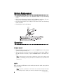
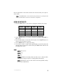
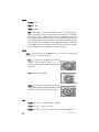
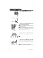
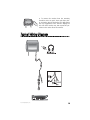
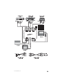
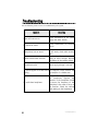
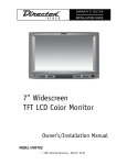
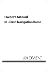
OWNER’S GUIDE INSTALLATION GUIDE 7” Widescreen TFT LCD Color Monitor Owner’s/Installation Manual MODEL HVM 702A © 2004 Directed Electronics, Inc. N81702A 12-04 NON-TRANSFERABLE LIMITED CONSUMER WARRANTY Directed Electronics, Inc. (Directed) promises to the original purchaser that the automotive video monitor and/or source unit(s) (the Product), excluding accessories, purchased and installed from a Directed authorized dealer within ninety (90) days after purchase of the new vehicle, in which the Product is installed, will be free from defects in materials or workmanship under normal use and conditions for a period of three (3) years from date of purchase or the first 36,000 miles as registered on the new vehicle's odometer reading at time of delivery of the Product for warranty service, whichever occurs first. Product purchased or installed more than ninety (90) days after the new vehicle is purchased are warranted for a period of one (1) year from date of purchase of the Product. Directed promises to the original purchaser that all video accessories will be free from defects in materials and workmanship under normal use and condition for a period of ninety (90) days after the date of purchase. A sales receipt and/or warranty registration card is required to provide proof of date of purchase of the Product or accessories. Should the Product prove to be defective during the applicable warranty period, the Product will be repaired or replaced with a new or comparable reconditioned part(s), at Directed's election. To obtain warranty service, the Product must be returned to a Directed authorized dealer along with proof of purchase and proof of installation by an Authorized Directed Dealer. This warranty is non-transferable and does not apply to any Product that has been modified or used in a manner contrary to its intended purpose, and does not cover damage to the Product caused by installation or removal of the Product. This warranty is VOID if the product has been damaged by accident or unreasonable use, negligence, acts of God, neglect, improper service or other causes not arising out of defect in materials or construction. This warranty does not cover the elimination of externally generated static or noise, or the correction of antenna problems or weak television reception, damage to tapes, video games, software, camcorders, discs, speakers, accessories or vehicle electrical systems, cosmetic damage or damage due to negligence, misuse, abuse, failure to follow operating instructions, accidental spills or customer applied cleaners, damage due to environmental causes such as floods, airborne fallout, chemicals, salt, hail, windstorms, lightning or extreme temperatures, damage due to accidents, road hazards, fire, theft, loss or vandalism, damage due to improper connection to equipment of another manufacturer, modification of existing equipment, use of a faulty tape cartridge or cleaning of the VCR head, or Product which has been opened or tampered with for any reason or which has been damaged due to alteration or service performed by anyone other than Directed Electronics, Inc. ALL WARRANTIES INCLUDING BUT NOT LIMITED TO EXPRESS WARRANTY, IMPLIED WARRANTY, WARRANTY OF MERCHANTABILITY, FITNESS FOR PARTICULAR PURPOSE, AND WARRANTY OF NON-INFRINGEMENT OF INTELLECTUAL PROPERTY ARE EXPRESSLY EXCLUDED TO THE MAXIMUM EXTENT ALLOWED BY LAW, AND DIRECTED NEITHER ASSUMES NOR AUTHORIZES ANY PERSON TO ASSUME FOR IT ANY LIABILITY IN CONNECTION WITH THE SALE OF THE PRODUCT. DIRECTED HAS ABSOLUTELY NO LIABILITY FOR ANY AND ALL ACTS OF THIRD PARTIES INCLUDING ITS LICENSED DEALERS OR INSTALLERS. IN NO EVENT WILL DIRECTED ELECTRONICS, INC. BE LIABLE FOR ANY INCIDENTAL, SPECIAL OR CONSEQUENTIAL DAMAGES (INCLUDING LOSS OF PROFITS), BY PURCHASING THIS PRODUCT, THE CONSUMER AGREES AND CONSENTS THAT ALL DISPUTES BETWEEN THE CONSUMER AND DIRECTED SHALL BE RESOLVED IN ACCORDANCE WITH CALIFORNIA LAWS IN SAN DIEGO COUNTY, CALIFORNIA. Some states do not allow limitation on how long an implied warranty lasts. In such states, the limitations or exclusions of this Limited Warranty may not apply. Some states do not allow the exclusion or limitation of incidental or consequential damages. In such states, the exclusion or limitation of this Limited Warranty may not apply to you. This Limited Warranty gives you specific legal rights, and you may have other rights which vary from state to state. 920-0002 Directed Video, 3 year Warranty Rev 11-04 2 Directed Video 3 year Automate RSE warranty 11-17-04.doc © 2004 Directed Electronics, Inc. Table of Contents Non-Transferable Limited Consumer Warranty . . . . . . . . . . . . . . . . . . . . . . . . .2 Important Notes . . . . . . . . . . . . . . . . . . . . . . . . . . . . . . . . . . . . . . . . . . . .4 Introduction . . . . . . . . . . . . . . . . . . . . . . . . . . . . . . . . . . . . . . . . . . . . . . .5 Features . . . . . . . . . . . . . . . . . . . . . . . . . . . . . . . . . . . . . . . . . . . . . . . . . .5 What is Included . . . . . . . . . . . . . . . . . . . . . . . . . . . . . . . . . . . . . . . . . . . .6 System Description . . . . . . . . . . . . . . . . . . . . . . . . . . . . . . . . . . . . . . . . . .6 Remote Control . . . . . . . . . . . . . . . . . . . . . . . . . . . . . . . . . . . . . . . . . . . . .7 Battery Replacement . . . . . . . . . . . . . . . . . . . . . . . . . . . . . . . . . . . . . . . . .8 Operation . . . . . . . . . . . . . . . . . . . . . . . . . . . . . . . . . . . . . . . . . . . . . . . . .8 Power On/Off ........................................................................................8 Mute....................................................................................................8 Menu (Adjustments) ...............................................................................9 Headrest Housing/Bezel Installation . . . . . . . . . . . . . . . . . . . . . . . . . . . . . .11 Headrest Installation . . . . . . . . . . . . . . . . . . . . . . . . . . . . . . . . . . . . . . . .12 Typical Wiring Diagram . . . . . . . . . . . . . . . . . . . . . . . . . . . . . . . . . . . . . . .13 Multiple A/V Input Selector . . . . . . . . . . . . . . . . . . . . . . . . . . . . . . . . . . . .14 Connecting a monitor to multiple sources................................................14 Troubleshooting . . . . . . . . . . . . . . . . . . . . . . . . . . . . . . . . . . . . . . . . . . . .16 Specifications . . . . . . . . . . . . . . . . . . . . . . . . . . . . . . . . . . . . . . . . . . . . .17 Notes . . . . . . . . . . . . . . . . . . . . . . . . . . . . . . . . . . . . . . . . . . . . . . . . . . .19 © 2004 Directed Electronics, Inc. 3 Important Notes 1. 2. 3. 4. 5. 6. 7. 8. 9. 10. 11. 12. 13. 14. 15. 16. 17. 18. 4 Before operating your LCD Monitor system, please read these instructions carefully. Retain this manual for future reference. Do not remove any WARNING stickers on the unit. Do not use any chemical solvent, cleaning agent or corrosive detergent to clean away dirt on the surface of the screen. Doing so may cause irreversible damage to the surface of the LCD screen. To clean off dirt or fingerprints, it is recommended that a soft-damp lens-cleaning cloth be used. Using spare parts from another manufacturer may cause permanent damage to the unit. Avoid installing the monitor screen in a position that is exposed to direct sunlight and hot air vents. Install the unit in a dry location, avoid condensation. Ensure that all wiring is properly connected before operating the unit. Should the LCD panel break, avoid contact with the broken glass or fluid leaking out from the enclosure. If you come into contact, flush and clean the affected areas with plenty of water. Seek medical attention immediately. When operating the monitor, avoid touching or pressing on the LCD screen. Excessive force will damage the LCD screen. When installing this unit in a vehicle, ensure that the installation and use of this unit is in compliance with local vehicle rules and regulations. Before replacing a blown fuse, turn the unit off and disconnect all power. Ensure the replacement fuse is of the same rating (5A) of the fuse being replaced. If during operation the unit overheats or malfunctions, turn off the power and contact your dealer. Do NOT disassemble the unit, there are no user serviceable parts in the unit. Ensure that no foreign objects are in the unit when the LCD screen is closed. The battery (CR2025) in the remote control has a useful lifetime of approximately 6-months. To ensure proper and reliable operation, replace the battery in a timely manner. When the unit is used in conjunction with a radio/TV tuner, reception quality will vary depending on the geographic location and weather conditions. The rated operating temperature range of the unit is 32º–92º F. Cool or warm the vehicle to within this temperature range prior to unit operation. The picture viewing quality of this LCD is dependent on the installed location. Adjust the brightness control and/or the angle of the screen to achieve the optimum visual quality. © 2004 Directed Electronics, Inc. Introduction Congratulations on your purchase of the world’s finest video entertainment system. At Directed we are committed to bringing you the most technologically advanced products available. We are pleased that you chose a Automate Video product. Through years of critical testing and hand craftsmanship, we have created a wide range of video entertainment products for your viewing pleasure. This system incorporates the use of on screen display menu controls that allows you to configure the system to suit your own personal preferences. For your listening flexibility, audio can be heard by optional infrared (wireless) headphones. To view other great products from Directed Electronics, please visit Automate at www.automatecarsecurity.com. Features z High definition, low reflection TFT LCD screen – 1440 (W) X 234 (H) z 16:9 wide screen ratio (full, 4:3, or wide selectable) z All functions can be operated from the remote control (power, volume, source select, etc.) z Picture noise eliminated by implementation of Blue screen z OSD (On Screen Display) of all functions z Brightness, color, and tint controls provided z Invert image control (Up/Down, Left/Right) z One-touch dimmer control z Low power consumption (750 mA at 12VDC) z Input voltage tolerance (9VDC–16VDC) z External A/V input z 2-ch IR wireless transmitter z Front headphone stereo output z PAL/NTSC manual select © 2004 Directed Electronics, Inc. 5 What is Included 7” TFT LCD Color Monitor Mounting hardware package Headrest housing EV sponge Headrest bezel DIN to RCA cable (for A/V input) Remote Control Unit/battery System Description MONITOR REMOTE CONTROL 19 8 18 17 9 10 16 11 12 1 2 3 4 5 6 15 14 13 7 MONITOR 1. 2. 3. 4. 5. 6. 7. Headphone jack Volume up/down buttons Wireless headphone IR transmitter Menu—changes the viewing aspect ratio (Full, 4:3, or Wide) Power On/Off button Remote control IR sensor receiver DIN jack for external audio/video input REMOTE CONTROL 8. Power On/Off button 9. SEL MUTE button—selects item on menu and serves as the mute On/Off button 6 © 2004 Directed Electronics, Inc. 10. Volume control—if the OSD is active, these allow scrolling through menu options 11. Menu On/Off—press the menu button to go back to the previous selection 12. Scan—used in conjunction with a TV tuner 13. A/M—used in conjunction with a TV tuner 14. TX—not used 15. DIM—dims the LCD screen 16. Up/down button for menu 17. MODE—changes the viewing aspect ratio (Full, 4:3, or Wide) 18. SOURCE—used in conjunction with a TV tuner 19. Remote IR LED—IR LED used to transmit commands to the monitor Remote Control 1. (S/T)—use these buttons to adjust the selected setting on the MENU screen. 2. SOURCE—press this button to select the video source (AV1/AV2). 3. MENU—press this button to display the MENU screen. Continue to press this button additional times to scroll through the MENU selections. 4. POWER—press this button to turn power on or off to the unit. © 2004 Directed Electronics, Inc. 7 Battery Replacement 1. Follow the instructions given in the illustration below to open the battery holder. 2. Remove the old battery and replace it with a CR2025 or equivalent. The positive (+) side of the battery must be facing upward in the clip. 3. Push the battery holder into the body of the remote control until the battery holder is locked. 4. Properly dispose of the old battery. 2 1 Operation POWER ON/OFF 1. Press any button on the LCD screen, or press the POWER button on the remote control to turn the monitor on. 2. To turn power off to the LCD screen press and hold the power button (PWR) on the LCD screen for 2-seconds, or press the POWER button on the remote control. NOTE: When using this monitor with a multiple A/V input selector (AV102); with power on, momentarity press the power button on the LCD screen to select AV1 or AV2 signal source. MUTE Press the power on/off button on the monitor to mute the audio, press again to restore the audio. NOTE: The power on/off button on the monitor does not mute the audio when there is an A/V input selector (VS102), in which case the button selects the A/V input. 8 © 2004 Directed Electronics, Inc. Press the SEL button on the remote control to the mute the audio, press again to restore audio. NOTE: If the MENU button on the remote has been pressed prior to pressing the SEL button, the SEL button now selects a menu item to be adjusted. MENU (ADJUSTMENTS) 1. Press the MENU button on the remote to display the following four groups: VIDEO Bright Color Tint Dimmer Reset AUDIO Volume Bass Mute H/P MODE Full 4:3 Wide DISP PAL/NT UP/DN LET/RIT 2. Use the S/T buttons on the remote to highlight the VIDEO, AUDIO, MODE, or DISP groups. 3. Press the SEL button to select the desired group. Use the S/T buttons to select the desired setting to change. 4. Use the W/X buttons to change the setting. 4. If no entry or action is taken within approximately 8-seconds the Menu will disappear and any changes are saved. Pressing the MENU button will also exit the adjustments screen. VIDEO BRIGHT(ness): 0–15 COLOR: 0–15 TINT: 0–15 DIMMER: ON–OFF (In the ON position the LCD screen is dimmed, which offers better veiwing at night or in dimly lighted envirorments.) RESET : YES–NO (This resets the unit back to the factory default settings for the above adjustments.) © 2004 Directed Electronics, Inc. 9 AUDIO VOLUME: 0–15 BASS: ON OFF MUTE: ON OFF H/P: A-CH B-CH — This setting allows the use of 2 headphones on different frequencies. If two video units are installed and; for example, each unit is playing a different video, using two headphones set at the same frequency may result in interference of the audio signal between the two headphones. One of the video units should be set to A-CH and the other to B-CH. A-CH is 2.3MHz left and 2.8MHz right, B-CH is 3.2MHz left and 3.8MHz right. Ensure that the headphones being used are of different receive frequencies, or are capable of 2-channel reception. MODE NOTE: In the Mode selection use the S/T buttons to select the desired setting and press SEL to set the selected video mode. FULL — A 4:3 picture is enlarged in the horizontal direction only, enabling viewing of a 4:3 picture (standard picture) without any clipping of the picture. 4:3 — Standard picture mode. WIDE — A 4:3 picture is enlarged in the same proportion both vertically and horizontally. This setting is ideal for cinema-sized pictures (wide-screen). DISP PAL/NT: PAL NT — video format (PAL or NTSC) UP/DN: UP DN — picture is inverted LET/RIT: LET RIT — picture is mirrored imaged (left-right swapped) 10 © 2004 Directed Electronics, Inc. Headrest Housing/Bezel Installation 1. Remove the cover from the headrest. 2. Using the headrest housing as a template, position the housing over the backside of the headrest and mark the foam with a felt tip pen. Cut the marked portion of foam and pull out the cut portion. 3. Insert the headrest housing into the headrest and secure the the headrest. Usually wire ties attached to the headrest posts is sufficient. NOTE: Ensure that the UP arrow on the headrest housing is pointing up. 4. Replace the cover over the headrest. Mark 11/2” from the inside of the headrest housing and cut the material away. 5. Optional Step: Glue the material to the inside of the headrest housing. Take care not to use excessive glue so that the headrest bezel is not glued to the headrest housing. NOTE: Glue is not required if the material of the headrest covering is of sufficient thickness to be tensioned by the headrest bezel. 6. Insert the headrest bezel into the headrest housing and secure the assembly using the provided hardware. NOTE: Ensure that the UP arrow on the headrest bezel is pointing up. © 2004 Directed Electronics, Inc. 11 Headrest Installation 1. Unplug the DIN cable from the monitor. 8-pin main DIN cable 5-pin adapter cable 2. Connect the LCD screen’s 8-pin DIN plug into the 8-pin DIN plug of the headrest. NOTE: When assembling the cable, match the arrows at each end of the connector. NOTE: Feed and orient the connector assembly behind the shroud mount in the lower right hand corner. You may have to feed some of the DIN cable up into the headrest to accomplish this positioning. 3. Position the monitor over the mounting shroud and apply even pressure to each corner of the monitor until the internal clips lock the monitor in place. NOTE: Do not press on the LCD screen as this will damage the screen. 4. Tape the end of the DIN plug to prevent damage to the pins. Then feed this cable from the hollow post of the headrest down through the seat back and connect it to the cable from the DVD player. NOTE: Ensure the cable does not entangle or interfere with the seat positioning/adjusting mechanism. 12 © 2004 Directed Electronics, Inc. 5. To remove the monitor from the mounting shroud for service or repair, insert and slide a plastic card at the edge of the monitor. This will remove the clip engagement of the monitor. Slightly lift this side of the monitor out, then repeat this procedure on the other side of the monitor. Typical Wiring Diagram © 2004 Directed Electronics, Inc. 13 Multiple A/V Input Selector Refer to diagram on the next page for the discussion that follows: CONNECTING A MONITOR TO MULTIPLE SOURCES When the monitor(s) power is turned on the input source will appear in the upper right hand corner (AV1, AV2, etc.). Press the SOURCE button on the remote to switch between the available sources for that monitor. NOTE: If PARKING is displayed on the screen, it means that this monitor(s) will not display video until the parking brake is set (vehicle parked). NOTE: You cannot change sources on video output 3 using the source selector, Only the remote will switch #3 output between the 3 video inputs. For operating convienence, when the system is connected to several other devices which have their own remotes, you can use those remotes through the HVM702a to operate the other devices. This is done by connecting the Remote Eye IR interface cable from the other devices to the R(emote) Sensor Input at the VS102 video selector. 14 © 2004 Directed Electronics, Inc. VS102 © 2004 Directed Electronics, Inc. 15 Troubleshooting Use the following chart to assist in troubleshooting the system. PROBLEM SOLUTION Power will not turn on Check connections to the power supply and other devices. No picture or sound Check connections of external device. Have picture, but no sound Remote control does not work Intermittent audio Check if the volume is set to low. If in A/V mode, check audio connections. Avoid using the product under strong & direct sunlight. Replace the battery in the remote control. Power supply voltage is too low. TV picture appear to shakes while Bad reception. Check antenna and driving try reception in a better area. No audio from headphone 16 Ensure the Power is switched on at the headphone. Replace the batteries in the headphone. Check to ensure the frequency of the headphone is the same as set up in the monitor. Check the volume level setting on the headphone. © 2004 Directed Electronics, Inc. Specifications Power 12VDC (9–16VDC) Power consumption 750mA Maximum @ 12VDC Power consumption (stand-by) 50mA Video type PAL/NTSC Video input level 1Vp-p, 75 ohm (composite) A-ch 2.3 MHz/2.8MHz IR frequency (left/right) B-ch 3.2 MHz/3.8MHz 1m ±30º IR range 1m ±15º Headphone stereo output 0.5 watts - 16 ohms/channel Actual screen size 155 (W) X 880 (H) mm Dimensions 189.4 (W) X 126.5 (H) X 35 (D) mm Weight 536 ±3 grams Remote control battery lithium battery CR2025, 3V NOTE: Specifications are subject to change without notice. © 2004 Directed Electronics, Inc. 17 18 © 2004 Directed Electronics, Inc. Notes ______________________________ ______________________________ ______________________________ ______________________________ ______________________________ ______________________________ ______________________________ ______________________________ ______________________________ ______________________________ ______________________________ ______________________________ ______________________________ ______________________________ ______________________________ ______________________________ ______________________________ ______________________________ ______________________________ © 2004 Directed Electronics, Inc. 19 The company behind this system is Directed Electronics, Inc. Since its inception, Directed has had one purpose, to provide consumers with the finest vehicle security, car stereo products, rear seat entertainment, and accessories available. The recipient of more than 20 patents in the field of advanced electronic technology, Directed is ISO 9001 registered. Quality Directed Electronics products are sold and serviced throughout North America and around the world. Call (800) 274-0200 for more information about our products and services. Directed® is committed to delivering world-class quality products and services that excite and delight our customers. Directed Electronics, Inc. Vista, CA 92081 www.directed.com © 2004 Directed Electronics, Inc.—All rights reserved N81702A 12-04