1
Warning
For your protection, please read the following:
Water and Moisture: Appliances should not be used near water
(e.g. near a bathtub, washbowl, kitchen sink, laundry tub, in a wet
basement, or near a swimming pool, etc.) Care should be taken so
that objects do not fall and liquids are not spilled into the enclosure
through openings.
These symbols are internationally accepted symbols that warn of potential
hazards with electrical products.The lightning flash means that there are
dangerous voltages present within the unit.The exclamation point indicates
that it is necessary for the user to refer to the owners manual.
These symbols warn that there are no user serviceable parts inside the unit.
Do not open the unit. Do not attempt to service the unit yourself. Refer all
servicing to qualified personnel. Opening the chassis for any reason will void
the manufacturer’s warranty. Do not get the unit wet. If liquid is spilled on
the unit, shut it off immediately and take it to a dealer for service.
Disconnect the unit during storms to prevent damage.
U.K. Mains Plug Warning
A molded mains plug that has been cut off from the cord is unsafe.
Discard the mains plug at a suitable facility. Never under any circumstances should you insert a damaged or cut mains plug into a 13
amp power socket. Do not use the mains plug without the fuse cover
in place. Replacement fuse covers can be obtained from your local retailer. Replacement fuses are 13 amps and MUST be ASTA approved to
BS1362.
Grounding or Polarization: Precautions should be taken so that
the grounding or polarization means of an appliance is not defeated.
Power Cord Protection: Power supply cords should be routed so
that they are not likely to be walked on or pinched by items placed
upon or against them, paying particular attention to cords at plugs,
convenience receptacles, and the point where they exit from the
appliance.
Servicing: To reduce the risk of fire or electrical shock, the user
should not attempt to service the appliance beyond that described in
the operating instructions. All other servicing should be referred to
qualified service personnel.
For units equipped with externally accessible fuse receptacle: Replace fuse with same type and rating only.
Safety Instructions
Electromagnetic Compatibility
Notice for customers if your unit is equipped with a power cord.
Operation is subject to the following conditions:
•This device may not cause harmful interference.
•This device must accept any interference received, including
interference that may cause undesired operation.
•Use only shielded interconnecting cables.
•Operation of this unit within significant electromagnetic fields
should be avoided.
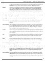
Warning:This appliance must be earthed.
The cores in the mains lead are colored in accordance with the following
code:
Green and Yellow - Earth Blue - Neutral
Brown - Live
As colors of the cores in the mains lead of this appliance may not correspond with the colored markings identifying the terminals in your plug, proceed as follows:
•The core which is colored green and yellow must be connected to the
terminal in the plug marked with the letter E, or with the earth symbol, or colored green, or green and yellow.
•The core which is colored blue must be connected to the terminal
marked N, or colored black.
•The core which is colored brown must be connected to the terminal
marked L, or colored red.
This equipment may require the use of a different line cord, attachment
plug, or both, depending on the available power source at installation. If the
attachment plug needs to be changed, refer servicing to qualified service
personnel who should refer to the table below.The green/yellow wire shall
be connected directly to the unit’s chassis.
CONDUCTOR
L
LIVE
WIRE COLOR
Normal
Alt
BROWN
BLACK
N
NEUTRAL
BLUE
WHITE
E
EARTH GND
GREEN/YEL
GREEN
Warning: If the ground plug is defeated, certain fault conditions in the unit
or in the system to which it is connected can result in full line voltage
between chassis and earth ground. Severe injury or death can then result if
the chassis and earth ground are touched simultaneously.
I
Power Sources: The appliance should be connected to a power
supply only of the type described in the operating instructions or as
marked on the appliance.
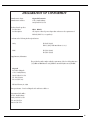
DECLARATION OF CONFORMITY
Manufacturer’s Name:
Manufacturer’s Address:
declares that the product:
Product Name:
Product Options:
Digitech Electronics
8760 S. Sandy Parkway
Sandy, Utah 84070, USA
RP21, RP21D
All (requires a Class II power adapter that conforms to the requirements of
EN60065, EN60742, or equivalent.)
conforms to the following Product Specifications:
Safety:
EN 60065 (1993)
IEC 65 (1985) with Amendments 1, 2 & 3
EMC:
EN 55013 (1990)
EN 55020 (1991)
Supplementary Information:
The product herewith complies with the requirements of the Low Voltage Directive
73/23/EEC and EMC Directive 89/336/EEC as amended by Directive 93/68/EEC.
Digitech
President of Digitech
8760 S. Sandy Parkway
Sandy, Utah 84070, USA
Tel: 801.566.8800
Fax: 801.566.7005
Effective February 10, 1999
European Contact: Your Local Digitech Sales and Service Office or
International Sales Office
8760 S. Sandy Parkway
Sandy, Utah 84070, USA
Tel. 801-568-7638
Fax 801-568-7642
II
We at Digitech are very proud of our products and back-up each one we sell with the following warranty:
1. The warranty registration card must be mailed within ten days after purchase date to validate this warranty.
2. Digitech warrants this product, when used solely within the U.S., to be free from defects in materials and workmanship under
normal use and service.
3. Digitech liability under this warranty is limited to repairing or replacing defective materials that show evidence of defect,
provided the product is returned to Digitech WITH RETURN AUTHORIZATION, where all parts and labor will be covered up to a
period of one year. A Return Authorization number may be obtained from Digitech by telephone. The company shall not be liable
for any consequential damage as a result of the product's use in any circuit or assembly.
4. Proof-of-purchase is considered to be the burden of the consumer.
5. Digitech reserves the right to make changes in design, or make additions to, or improvements upon this product without
incurring any obligation to install the same on products previously manufactured.
6. The consumer forfeits the benefits of this warranty if the product's main assembly is opened and tampered with by anyone other
than a certified Digitech technician or, if the product is used with AC voltages outside of the range suggested by the
manufacturer.
7. The foregoing is in lieu of all other warranties, expressed or implied, and Digitech neither assumes nor authorizes any person to
assume any obligation or liability in connection with the sale of this product. In no event shall Digitech or its dealers be liable
for special or consequential damages or from any delay in the performance of this warranty due to causes beyond their control.
Digitech™, S-DISCII™, Whammy™, and Silencer II™ are registered trademarks of the Harman Music Group Incorporated.
NOTE: The information contained in this manual is subject to change at any time without notification. Some information contained in this
manual may also be inaccurate due to undocumented changes in the product or operating system since this version of the manual was
completed. The information contained in this version of the owner's manual supersedes all previous versions.
III
Table of Contents
Safety Information....................................................................................................I
Declaration of Conformity ......................................................................................II
Warranty ..................................................................................................................III
Table of Contents ....................................................................................................IV
Section One - Introduction
Congratulations........................................................................................................1
Included Items ........................................................................................................1
Product Features ......................................................................................................1
Quick Start................................................................................................................2
A Guided Tour of the RP21 ..................................................................3
The Front Panel......................................................................................3
The Rear Panel ......................................................................................4
Getting Started ....................................................................................................5
Making Connections ..............................................................................5
Mono ....................................................................................................5
Stereo ....................................................................................................6
Direct to Console ..................................................................................6
Digital Output ........................................................................................6
Powering................................................................................................7
About the RP21 ......................................................................................7
Program Mode ......................................................................................7
The Display ............................................................................................7
The Programs ........................................................................................8
The Footswitches....................................................................................8
The Expression Pedal ............................................................................8
The Effects..............................................................................................8
Preamp/Analog Modules ........................................................................9
Digital Effects Modules ..........................................................................9
Section Two - Editing Functions
Selecting a Program ..............................................................................10
Creating Programs..................................................................................10
Preamp Defaults......................................................................................10
Editing the Preamp ................................................................................10
The Preamp Effects ................................................................................10
Compressor............................................................................................11
Wah........................................................................................................13
Tube Distortion ......................................................................................13
Saving a Distortion Default ....................................................................14
Solid State Distortion..............................................................................15
10 Band Graphic EQ ..............................................................................16
Noise Gate ..............................................................................................17
Master Preamp Setting ..........................................................................19
Storing a User Preamp Default ............................................................21
Naming a Default ....................................................................................21
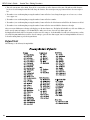
Default List ..............................................................................................22
Digital Effects ..........................................................................................24
Configuration Chart................................................................................24
Changing Effects......................................................................................25
Effect Types ..............................................................................................28
Choruses & Flangers ..............................................................................28
Chorus ..................................................................................................28
Flanger ..................................................................................................30
Phaser....................................................................................................31
Pedal Phaser ..........................................................................................31
Rotary Speaker ......................................................................................32
Trmolo and Panner ................................................................................32
Temolo ..................................................................................................33
Panner ..................................................................................................33
Delays ....................................................................................................33
Multi Effects Modules ............................................................................35
Reverse Delay ........................................................................................36
Time Warp ............................................................................................36
Samplers ................................................................................................36
Reverb....................................................................................................37
Gated Reverb..........................................................................................38
Detuners ................................................................................................40
Pitch Shifters and Harmony....................................................................41
Whammy Effects ....................................................................................43
Auto Wah................................................................................................43
Equalizers ..............................................................................................44
Graphic Equalizers ................................................................................44
Parametric Equalizers ............................................................................45
Master Mix ..............................................................................................46
Cabinet Emulator ..................................................................................46
Storing/Copying Programs ....................................................................47
Section Three - Advanced Topics
Footcontroller Fuctions ........................................................................48
Assigning Programs................................................................................48
Assigning on/off Functions ....................................................................48
Expression Pedal Assignments ............................................................49
Assigning the Wah ..................................................................................50
Assigning Morph or Volume ..................................................................50
Modifiers..................................................................................................51
Dynamic Filters ......................................................................................51
Low Frequency Oscillators ....................................................................51
MIDI CC’s ..............................................................................................51
Assigning a Modifier ..............................................................................51
Viewing, Changing, or Deleting Assignments ....................................52
Tuner ........................................................................................................53
Section Four - Utilities
Output Mode............................................................................................54
Cabinet Emulator ....................................................................................54
MIDI Channels ........................................................................................54
Program Receive Map ............................................................................55
Program Transmit Map ..........................................................................55
SysEx Channel and MIDI Merge ..........................................................56
SysEx Dump ............................................................................................56
Program Dump........................................................................................57
User Defalut Dump ................................................................................57
Assigning a MIDI CC to Pedals ............................................................58
Bank Names ....................................................................................59
Volume Pedal Update ............................................................................59
Factory Reset ..........................................................................................59
Recalibrating the Expression Pedal ....................................................60
Section Five - Appendix
Factory Program List ..................................................................................61
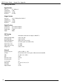
Specifications ..........................................................................................62
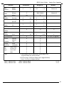
MIDI Implementation Chart..................................................................63
IV
RP21D User’s Guide
Section One - Introduction
Section-1 Introduction
Congratulations on your purchase of the Digitech RP21D!
The DigiTech RP21D is one of the most powerful preamp processors in the world. The exclusive dual preamp paths, and palette of great
digital effects, combined with the flexible routing and a digital output make the RP21D an extremely versatile sound shapingtool for your
music in the studio or on stage. This user’s guide is your key to understanding how to get the most out of the RP21D. Please read it carefully
and familiarize yourself with the controls.
Your RP21D was carefully assembled and packaged at the factory. Before you proceed any further, make sure the following items are
included:
• (1) User’s Guide
• (1) RP21D Preamp Processor
• (1) DigiTech Warranty Card
• (1) PS0940 or PS0920 Power Supply
Please take a moment to fill out the warranty registration card, and be sure to save all packing materials. The warranty is your safeguard in
the unlikely event that the unit requires servicing, and the packing materials should be used to return the unit.
Once again, thank you for your purchase, and enjoy your RP21D.
RP21D Features:
• Dual Preamp Path
• Built-in Expression Pedal
• Tube Preamp (12AX7)
• Full Band Width Effects (20 Hz-20 kHz)
• 24-bit Signal Path, 48-bit Internal Data Path
• Up to 4 Digital Effects at once
• Flexible Effect Routing
• S-DISC II Processing
• Programmable Speaker Cabinet Emulator
• Chromatic Tuner
• Full MIDI Implementation
• S/PDIF Digital Outputs
• Continuous Control of All Effects and Parameters
• Simple User Interface
1
RP21D User’s Guide
Section One - Introduction
Quick Start
The RP21D comes with 128 pre-programmed factory presets, and 128 user presets. You will find that from the factory, the user presets are
exact duplicates of the factory presets. This allows you to experiment without running the risk of losing any of the original sounds contained
in the RP21D.
For those of you who prefer to burn now and read later, we’ve included this Quick Start section to get you up and running.
Making Connections:
Connect your instrument to the input jack on the rear panel. Connect from the Left Output (for mono operation), or the Left and Right
Outputs (for stereo operation) to the input(s)of your amplifier(s) or power amp.
Apply Power:
Turn the Output knob on the rear panel of the RP21D all the way down (fully counter clockwise). Connect the plug of the PS0940 power
supply to the power jack on the RP21D. Connect the other end of the PS0940 power supply to an AC outlet. Begin playing your instrument
and adjust the Input Level knob until the Input Clip LED flashes with strongest signal, then slightly reduce the Input Level. Turn the power of
your amplifier(s) to the on position. Gradually increase the Output knob to achieve the desired volume.
Select Program:
Use the Footswitches or the Data Wheel to scroll through the different programs. Once you have found some Programs that suit your taste,
you can alter the sounds to your specific needs. By pressing the Effects button, you can roll the Data Wheel to access any of the effects
contained within your selected Program. The 1-4 buttons will select the specified parameters related to each effect. The Next Page, and
Previous Page buttons will display all of the pages of related effect parameters. Once a parameter has been selected, you may increase or
decrease the parameter value with the Data Wheel. You can adjust any of these parameters to your liking, and remember that you are not at
risk of losing any sounds so, don’t be afraid to experiment.
2
RP21D User’s Guide
Section One - Introduction
A Guided Tour of the RP21D
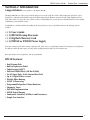
The Front Panel
D
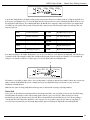
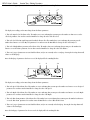
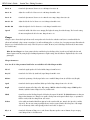
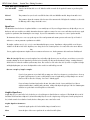
1. Footswitches - The footswitches are used to call up Programs, change banks, access the tuner, bypass all effects, turn individual effects
on and off, or change the value of a specific parameter.
2 Display - The display provides all information regarding the current Program, parameter edit functions, utility set up, and tuning
indications.
3. Store Button- The Store button is used to save your custom edits to the user Programs. This button will light when changes have been
made to any Program, indicating that to retain these changes, they must be stored.
4. Program Button- The Program button lights to indicate that you are in the Program mode as opposed to edit mode. While in Program
mode, the RP21D provides access to all Programs, and the ability to turn effects on or off. You cannot modify your
Programs in the Program mode. This button can act as an escape key taking you out of edit mode, or if you are
already in Program mode, you can toggle from factory to user Programs by pressing and holding this button.
5. 1-4 Buttons - These buttons will access the parameters shown in the display. Each parameter in the display will have a number next to
the parameter. The parameters can be accessed by pressing the button corresponding to the the numbered parameters.
6a. Preamp Button - The Preamp button will provide direct access to the effect modules in the Preamp section of the RP21D. This button
will light when you are editing modules in the Preamp section.The modules in the Preamp section include the
Compressor, Analog Wah, Tube Distortion, 10 band Graphic EQ for the Tube Distortion, Solid State Distortion, 10
band Graphic EQ for the Solid State Distortion, and Noise Gate. Successive presses of the preamp button will
advance to the next effect module in the Preamp section.
6b. Effects Button - The Effects button provides direct access to the effect configurations as well as the individual digital effect modules.
This button will light while you are editing effects in the digital section of the RP21D.Successive presses of the Effects
button will advance to the next digital effect module in the current configuration.
3
RP21D User’s Guide
Section One - Introduction
6c. Utility Button - This button will provide access to the utility functions in the RP21D. This button will light when you are in the Utility
menu.Once in the Utility menu, you may use the Previous Page and Next Page buttons to select any of the 15 pages of
Utilities. The Utility menu includes Output mode, MIDI functions, System Exclusive dumps, Bank Names,
Reinitialization menu, and Expression Pedal Calibration menu.
6d. Previous Page Button - The RP21D may have several “pages” of parameters or menus for a particular section of programing. The
Previous Page button will allow you to step backwards through these pages of menus or parameters.
Successive presses of the Previous Page button will back step by one page for each press. This button will
light when an effect or menu contains more than one page.
6e. Next Page Button - The RP21D may have several “pages” of parameters or menus for a particular section of programing. The Next
page button will allow you to advance forward through the pages or menus. Successive presses of the Next Page
button will advance forward by one page for each press. This button will light when an effect or menu contains
more than one page.
6f. Assign Button - The Assign button is used to assign Programs, effect on/off functions, or parameters to the expression pedal,
footswitches, or MIDI CC’s. It is also used for viewing pedalboard assignments, or adjusting minimum/maximum
values of assigned parameters. This button will light while in the assignment menu. Making assignments is as easy as
selecting the Program or parameter that you wish to assign, pressing the assign button once, and selecting the
footswitch or pedal that you wish to use to access the Program or parameter. See page 48 for more on assigning
functions to the pedalboard.
7. Data Wheel - This rotary knob is used to scroll through Programs, adjust parameter values, or change the status of any function
currently selected in the display.
8. Expression Pedal - The Expression Pedal is used for real time control of parameters during performance. This pedal may control
volume in one Program, wah in another Program, morph between the tube and solid state preamp in another
Program, or vary the delay time in yet another Program. Individual boundaries may be set up for the minimum and
maximum parameter values that will be accessed by the Expression Pedal. See page 49 for more on making
expression pedal assignments.
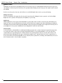
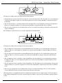
Rear Panel
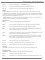
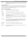
1. Input Jack - This is where your signal enters the RP21D. Connect from the output of your instrument to this jack.
2. Input Level - This knob adjusts the strength of the signal as it enters the RP21D. Set this level so that the clip LED lights occasionally
with strong signals.
3. Clip LED - This LED will light when the input signal is overdriving the input of the RP21D. The Input Level knob should be adjusted in
conjunction with watching this LED. The Clip LED should light occasionally with strong signal.
4. Output Level - This knob controls the level of signal coming out of the RP21D.
5. Right Output - This jack should be used for stereo applications. Connect from this output to the input of a second amplifier, or the
right input of a stereo power amp.
4
RP21D User’s Guide
Section One - Introduction
6. Left/Mono Output - This output should be used for all stereo and mono applications. Connect from this jack to the input of your
amplifier, or the left input of a stereo power amp. If the RP21D is to be used in a mono application, set the Output
Mode to mono in the utility menu.
7. Headphone Output - This jack delivers a speaker compensated, stereo signal. Connect stereo headphones to this jack. Do not connect
a mono jack here as doing so may damage the output driver.
8. Power Input - This connector is used to power the RP21D. Use only the DigiTech PS0940 power supply provided.
9. MIDI In - This jack is used to receive all incoming MIDI data intended to control the RP21D. Connect from this jack to the MIDI out of
a sequencer, MIDI controller, or MIDI storage device.
10. MIDI Out/Thru - This jack is used for all MIDI data being sent out of the RP21D. Connect from this jack to the MIDI input of any
external MIDI devices that you wish to control. The MIDI Thru function of this jack simply sends out the same
information that is received at the MIDI In of the RP21D.
11. S/PDIF Output - This is the digital output from the RP21D. The signal at this output is in a digital format, and is to be connected to a
digital S/PDIF input such as those found on digital recorders.
Getting Started
Making Connections
Before connecting the RP21D, make sure that the power to your amplifier is turned off, and that the power to the RP21D is disconnected.
There is no power switch on the RP21D. To turn the RP21D on, simply plug the power supply in to an AC outlet. To turn the RP21D off,
unplug the power supply from the AC outlet.
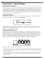
There are several different amplification options available when using the RP21D. You may run mono into an amp or power amp, stereo into
two amps or a stereo power amp, direct into a mixing console, or a combination of amp(s) and mixing console. The following diagrams
show the connections for some of these options.
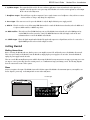
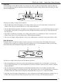
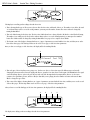
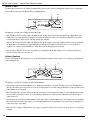
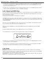
Mono
Connect your guitar to the input of the RP21D. Connect the Left Mono output of the RP21D to the instrument input on your amplifier, or to
the line input of a power amp. Set the Output Mode to mono in the utility menu.
Left Mono output
Input
D
5
RP21D User’s Guide
Section One - Introduction
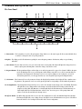
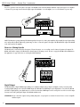
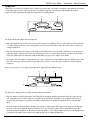
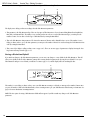
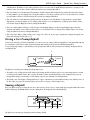
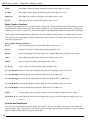
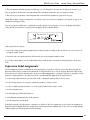
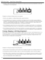
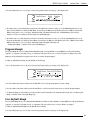
Stereo
For stereo operation connect the guitar to the input of the RP21D. Connect from the RP21D’s Left/Mono output to the input of one amplifier
or channel of a power amp. Connect from the Right output of the RP21D to a second amplifier, or to a second channel of a power amp.
Input
D
Right output
Left Mono output
Right input
Left input
Stereo 100 Power Amp
NOTE: The RP21D is a preamp. Running The RP21D signal into the input of a combo guitar amplifier will preamplify the signal again adding
noise and possibly feedback. When using a guitar amp, it is best to connect the guitar to the input of the RP21D and the output of the RP21D
to the effect return of the amplifier.
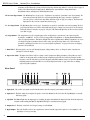
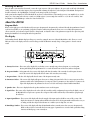
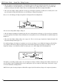
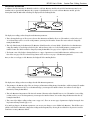
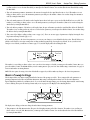
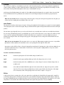
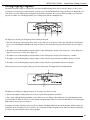
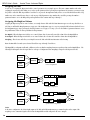
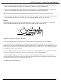
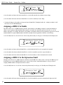
Direct to a Mixing Console
The RP21D can be connected directly to the inputs of a house PA system, or to a recording console. Connect the guitar to the input of the
RP21D, and from the outputs of the RP21D to the channel inputs of the mixing console. Be sure to engage the RP21D’s Cabinet Emulator in
this application. See page 46 for more on selecting the Cabinet Emulator.
Input
D
Right Output
Left (Mono) Output
4
6
4
2
6
4
8 2
0
6
0
6
0
0
+2
0
-2
0
0
-2
0
-2
0
-2
0
-2
+2
Pan
Mute
+10
+10
+10
+10
+5
+5
+5
+5
+5
0
0
0
0
0
0
0
0
-5
-5
-5
-5
-5
-5
-5
-5
-10
-10
-10
-10
-10
-10
-10
-10
-20
-20
-20
-20
-20
-20
-20
-20
-30
-°
-30
-°
-30
-°
-30
-°
-30
-°
-30
-°
-30
-°
-30
-°
6
+5
L/R
+10
+5
5
Pan
Mute
L/R
+10
+5
4
+2
+3
+10
3
+1
+4
-5
+5
+5
2
0
-2
+3 -3
+4 -4
-5
+5
+10
1
10
Aux 2
-1
+1
+3 -3
L/R
6
8
0
10
Aux 2
-1
+2
Pan
10
Aux 1
4
+4 -4
-5
Mute
L/R
0
+1
+3 -3
+5
6
8
6
8 2
10
Aux 2
-1
+2
Pan
4
0
10
Aux 1
4
+4 -4
-5
Mute
L/R
0
+1
+3 -3
+5
6
8 2
6
8 2
10
Aux 2
-1
+2
Pan
4
0
10
Aux 1
4
+4 -4
-5
Mute
L/R
0
+1
+3 -3
+5
6
8 2
6
8 2
10
Aux 2
-1
+1
+2
Pan
4
0
10
Aux 1
4
+4 -4
-5
Mute
L/R
L/R
0
-2
+3 -3
+5
6
8 2
6
8 2
10
Aux 2
-1
+2
Pan
4
0
10
Aux 1
4
+4 -4
-5
+5
Mute
Mute
0
+1
+3 -3
Pan
6
8 2
10
Aux 2
-1
+1
+4 -4
-5
6
8 2
0
10
Aux 1
4
8 2
10
Aux 2
-1
-2
-4
4
8 2
0
10
Aux 1
4
8 2
-3
6
8 2
0
10
Aux 1
4
2
7
8
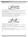
Digital Output
The RP21D includes a digital S/PDIF output enabling you to eliminate multiple analog to digital, and digital to analog conversions when
recording digitally. Simply connect from the S/PDIF output of the RP21D to the S/PDIF input on your digital mixer or recorder. The RP21D
will deliver a digital signal to your digital mixer or recorder. You must have S/PDIF inputs on the receiving device in order to use this output.
You may use the analog and digital outputs of the RP21D simultaneously.
ATTENTION: Do not connect this output to analog auxilary, CD, phono, or tape inputs on consumer electronic devices. It is not compatible
with these inputs.
6
RP21D User’s Guide
Section One - Introduction
Powering the RP21D
Once the audio connections have been made, connect the 4 pin connector of the power adapter to the power jack on the back of the RP21D
and the other end to an AC outlet. Begin to play your guitar while adjusting the Input Level on the back panel of the RP21D. The Input Level
should be adjusted so the clip LED lights occasionally on the strongest peaks of your signal.
At this point, turn the Output Level of the RP21D all the way down (counterclockwise). Then turn the power to your amplifier(s) on. Set the
amp(s) to a clean setting and set the tone controls to a flat EQ response (on most amps, this would be 0 or 5 on the tone controls). Turn
the Output Level of the RP21D up to achieve the desired volume level.
About the RP21D
Program Mode
When you first apply power to the RP21D, it will power up in Program mode. Program mode is indicated when the Program button is lit and
is the mode used while you are performing. Using the footswitches while in Program mode allows you to access different Programs, turn
effects on and off, access the tuner, bypass all effects, change banks, or adjust the values of any parameters assigned to the expression pedal.
Rotating the Data Wheel selects Programs in the Program mode.
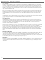
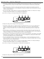
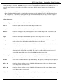
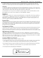
The Display
Understanding what the RP21D’s display is telling you is crucial to getting the most out of what the RP21D has to offer. There are several
different sections to the display, and each section is telling you what the RP21D is currently doing, or listing options to alter the current
sound.
B
D
C
%kHz
msdB
LINK CHANGED
LINK CHANGED
COMP
A
USER
BANK
PAGE
OF
H
%kHz
msdB
WAH
TUBE
G
LINK CHANGED
LINK CHANGED
GATE
EQ
#
b
%kHz
msdB
%kHz
msdB
L/R OUTS
E
CLIP
F
A. Factory/User Icon - This section of the display tells you whether you are currently using a factory Program, or a user Program.
Pressing and holding the Program button for 2 seconds will switch between the factory and user Programs.
B. Program Number - In Program mode, this section of the display will show the number of the currently selected Program. In tuner
mode, this section of the display will show the name of the note that you are tuning.
C. Program Name - This line of the display will show the name of the Program currently active.
D. Parameter Values - This section of the display will appear when you are editing a Program. Each of the 4 sections represent an effect
parameter and the value of that parameter. Accessing any of these 4 parameters is done with the 1-4 buttons to the
right of the display. Once the parameter has been accessed, the value may be adjusted with the Data Wheel.
E. Speaker Icon - This icon is displayed when the speaker simulator is active in the Program.
F. Signal Flow - This section of the display shows the order of the effect modules and the configuration being used in the digital section of
the RP21D. Each box represents a separate effect. A bypassed effect will be indicated by a horizontal line going through
the effect box.
G. Input Signal/Tuner - This section of the display will show the strength of the input signal to the Effects section. This section of the
display also functions as a tuning indicator. While in the tuner mode, the Program number will show the note you
are tuning, and this line will provide indications as to whether you are sharp, flat, or in tune.
H. Bank/Page Number - This section of the display will show the Bank number that is currently active when you are in Program mode.
While in edit mode, this section will show how many pages of parameters are associated with a particular editing
function, and which page you are currently on.
7
RP21D User’s Guide
Section One - Introduction
The Programs
Programs are named and numbered locations of sounds that have been programmed into the RP21D. Programs can be recalled with the
footswitches or the Data Wheel. The RP21D comes with 128 factory and 128 user Programs available. The factory Programs will not allow
you to store any changes to them. The user Programs are locations where your creations may be stored. You will notice that the 128 user
Programs are exact duplicates of the 128 factory Programs. This allows you to make your own Programs without worrying about losing any
of the sounds that the RP21D came with.
When you select a Program, the name and number of the Program will be shown in the display. An icon directly beneath the number of the
Program will indicate whether the Program is a factory Program or a user Program. Depending on whether or not you have changed any
footswitch assignments, the top row of footswitches may have one or more LEDs lit, indicating the status of the effects assigned to those
switches.
The RP21D includes a variety of different Programs. Go ahead and audition several of the Programs. Once you have found some sounds that
are close to what you are looking for, you can edit those Programs until they are exactly what you want.
The Footswitches
The RP21D includes 12 footswitches which can be assigned to perform different functions. The footswitches can call up Programs, turn
effects on or off within a Program, change banks, bypass the Program, or access the tuner. Other functions can also be performed with the
footswitches such as setting up a delay time by tapping your foot on a switch in time with the tempo of a song. You can also use the
footswitches to change a parameter to a specific value.
From the factory, the footswitches have been set up to call up Programs with the bottom row (switches 1-5), and turn effects on and off with
the top row (switches 6-0). You may change assignments to any of these ten switches to suit your needs. For more on assigning the
switches, see page 48. The top and bottom switches on the far right (next to the expression pedal) cannot be reassigned. These switches are
permanently assigned to advance banks with the top switch, or decrement banks with the bottom switch. The top right switch will also
bypass the current Program by pressing and holding the switch. The bottom right switch will access the tuner by pressing and holding the
switch.
The Expression Pedal
As you go through the different Programs that came in the RP21D, you will find that the expression pedal has different functions. This pedal
can be assigned to control any parameter of any effect in the RP21D. Rocking the pedal back and forth will change the value of the
parameter that the pedal has been assigned to control. You may assign minimum and maximum values (stop points) for each parameter that
you control with the pedal. For more on assigning the expression pedal, see page 49.
The Effects
Creating your own signature sound with the RP21D is easy and intuitive. The RP21D is divided into two sections of effect modules: the analog
or preamp modules, and the digital effect modules. Each section may be accessed individually for the purpose of modifying the available
effect modules.
8
RP21D User’s Guide
Section One - Introduction
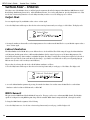
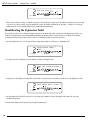
Preamp/Analog Modules
Access to all of the preamp modules is accomplished by pressing the Preamp button. Once pressed, an effect module in the preamp section
of the display will begin to flash indicating which module you have accessed. Successive presses of the Preamp button will advance to the
next module in the preamp section. Each module will have various parameters available for editing. Each parameter will be preceded by a
highlighted number between 1 and 4. Use of the 1-4 buttons will select the corresponding numbered parameter. There may be more than
one page of parameters associated with the effect module. This will be indicated by the Next and Previous Page buttons being lit. The bottom
left corner of the display will show which page you are on, and how many pages are associated with that effect. When you have selected the
parameter to be edited, rotating the Data Wheel will change the value of the parameter. You will be able to hear your changes in real time.
100
Edge of the Earth
1
%kHz
%kHz
%kHz
%kHz
50msdB 2 60
msdB 3 70 msdB 4 100 msdB
LINK CHANGED
LINK CHANGED
COMP
WAH
LINK CHANGED
TUBE
EQ
LINK CHANGED
GATE
L/R OUTS
DIST
USER
BANK
PAGE
10 OF1 1
Preamp Effect Modules
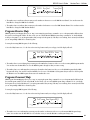
Digital Effects Modules
Access to all of the digital effects modules is accomplished by pressing the Effect button. The first press of the Effect button will take you to
the configuration menu of the digital section. The RP21D includes 15 different configuration to choose from. Each configuration will change
the signal routing through the digital effects, the number of effect modules, and the processing power available to each of the effect modules.
Every time that you change configurations, you will start out with a “blank slate” of digital effect modules. In other words, changing the
configuration will cause all digital effect modules to default to “thru modules,” meaning that you will have to choose the effect for each
module. Once you have selected the desired configuration, press the Effects button again and the first module in the selected configuration
will begin to flash indicating which module you are about to edit. Successive presses of the Effects button will advance to the next module in
the digital section of the RP21D. After you have selected the module that you wish to edit, use the 1-4 buttons to select the parameter that
you want to modify. There may be more than one page of parameters associated with the effect module. This will be indicated by the Next
and Previous Page buttons being lit. The Bank/Page section of the display will show which page you are on, and how many pages are
available. When you have selected the parameter to be edited, rotate the Data Wheel to change the value of the parameter. You will be able to
hear your changes in real time.
100
USER
Edge of the Earth
1
%kHz
%kHz
%kHz
%kHz
50msdB 2 60
msdB 3 70 msdB 4 100 msdB
LINK CHANGED
LINK CHANGED
COMP
WAH
TUBE
LINK CHANGED
EQ
LINK CHANGED
GATE
L/R OUTS
DIST
BANK
PAGE
10 OF1 1
Digital Effect Modules
9
RP21D User’s Guide
Section Two - Editing Functions
Section Two - Editing Functions
Selecting a Program
When creating or editing a sound, you must first start by choosing a Program. The Program number does not necessarily need to be the
location which you intend to have the sound reside, as you can save your creation to any user Program number during the store process.
You do have to start with one of the user or factory Programs. It is not possible to start with a completely empty Program. Pick a Program
which will be your starting point.
Creating Programs
The RP21D lets you create your own Programs, or fine tune the original settings to suit your needs. Editing and creating is a very simple
process that doesn’t require a lot of time dedicated to learning the menus. Once a Program has been edited to your liking, you may store
those settings to any of the 128 user Programs. Remember that the user Programs are duplicates of the factory Programs so, you are not at
risk of losing any of the sounds that the RP21D came with.
Preamp Defaults
Once you have selected the Program, press the Preamp button once. All of the modules in the Preamp section will begin flashing in the
display. This is the default page of the Preamp. A default is a way of quickly getting several effects and/or parameters set up without having to
Program each one individually. It remembers the settings of all of the preamp effect modules and will set all parameters to the values stored
in the default. There are 30 factory and 30 user preamp defaults in the RP21D. You can choose one of the factory preamp defaults that suits
your needs, or tailor your basic sound to get a custom preamp tone that you will want to use for several other Programs. You can then store
your custom default to a user default location. Then when you create a new Program in which you wish to use that same preamp tone, all
you have to do is select the same default setting. This saves you the time and hassle of reprograming the preamp every time you create a
Program.
Editing the Preamp
Let’s suppose that you are not going to use a default for the preamp, or that you are going to create a custom default setting. This means that
you will need to edit all the effects in the preamp individually. To access the effects within the preamp, press the preamp button twice. The
Compressor box will begin to flash indicating that you are about to edit the compressor module. Successive presses of the preamp button
will advance through all of the effect modules in the preamp section. Once you reach the end of the preamp modules, the RP21D will “loop
around” and start at the beginning again. Every module will have parameters associated with that effect available for editing. These
parameters will be shown in the 1-4 positions of the display. To adjust any of these parameters, press any of the 1-4 buttons and an arrow
will appear next to the corresponding parameter. Rotate the Data Wheel to change the value of that parameter.
When the preamp has been edited to suit your requirements, you may store the settings to a user default for use in other Programs, or move
on to editing your digital effects within the current Program.
The Preamp Effects
The preamp contains a total of 7 different effects. The effects were laid out in the most logical and best sounding order and cannot be
changed. The guitar signal can go through any or all of the modules. The first effect that your guitar goes through is the compressor. The
output of the compressor is then fed to the Wah. After the Wah effect, the signal can be split and run through two discrete Distortion paths.
Each Distortion path has a dedicated Equalizer. The expression pedal can be assigned to morph between the two Distortion paths (see page
50 for more information on morphing). The outputs of the Equalizers are sent into a Noise Gate which is the end of the Preamp effect
modules. Each effect in the preamp (except for the Wah) includes a default menu exclusive to that effect.
10
RP21D User’s Guide
Section Two - Editing Functions
Compressor
Compression is a tool that sets boundaries for the strength of your guitars signal. A bi-product of containing a signal within these boundaries
is long lasting sustain, as well as a tight, smooth texture. Selecting the Compressor is done by pressing the Preamp button until the
Compressor module is flashing in the display. The display will look something like this:
1
4
FACTORY
USER
BANK
PAGE
OF
1
3
2
Compressor
1 On %kHz
msdB 2 LINK CHANGED
Heavy
%kHz
msdB
%kHz
msdB
LINK CHANGED
COMP
WAH
SEAMLESS
4 F 5%kHz
msdB
LINK
TUBE
EQ
DIST
EQ
b
LINK
GATE
#
DIGITAL
CLIP
L/R OUTS
3
The display will show three things about the Compressor.
1. This is showing that the type of effect you are about to edit is a Compressor, and that the effect is on. The number 1 icon before the word
“on” indicates that in order to access the on/off parameter, you need to press the number 1 button. The status can then be changed by
rotating the Data Wheel.
2. This is the default setting for the Compressor. The Compressor default shown here is factory default 5 (F5)which is a heavy Compression
setting. The number 4 which precedes the F5 value, indicates that in order to access the default parameter, you must press the number 4
button. The default can then be changed by rotating the Data Wheel. See page 22 for a complete list of defaults.
3. The bottom corner of the display is showing that there are 3 pages of parameters associated with the Compressor, and that you are on the
first of these three pages. The next and previous page button can be used to access the other pages of parameters associated with the
Compressor.
When you access page two of the compression parameters, the display will look something like this:
1
4
4
FACTORY
USER
BANK
PAGE
OF
2
3
3
ThreshRatio AttackMedium
%kHz
%kHz
1 -14
msdB 22 9.00
msdB 3
LINK CHANGED
SEAMLESS
b
2
LINK CHANGED
COMP
WAH
LINK
TUBE
EQ
DIST
EQ
2
%kHz
msdB
4
%kHz
msdB
LINK
GATE
#
DIGITAL
CLIP
L/R OUTS
The display it now telling you four more things about the Compressor parameters
1. This is the Compressors Threshold parameter. The Threshold is the strength the incoming signal must be before the compression will
start. A signal above this level will be compressed, a signal below this level will not. The number 1 icon is telling you that in order to
access the Threshold parameter, you must press the number 1 button. Then you can adjust the Threshold value by rotating the Data
Wheel.
2. This is the Compressors Ratio parameter. The Ratio is the amount of compression that will be applied to the signal once the Threshold
has been exceeded. In the display shown above, the Ratio is 9 to 1 (the 1 is implied). A Ratio of 9 to 1 means that for every 9 dB of
incoming signal, there will only be a 1 dB increase in output. The number 2 icon is telling you that in order to access the Ratio parameter,
you must press the number 2 button. Then you can adjust the Ratio value by rotating the Data Wheel.
11
RP21D User’s Guide
Section Two - Editing Functions
3. This is the Compressors Attack Time parameter. The Attack Time parameter adjusts the length of time that it takes the compressor to
reach the full Ratio once the Threshold has been exceeded. The number 3 icon is telling you that in order to access the Attack Time
parameter, you must press the number 3 button. Then you can adjust the Attack Time value by rotating the Data Wheel.
4. This section of the display is telling you that there are three pages of Compression parameters, and that you are currently on the second
page. Pressing the Next Page button will advance you to the third page of Compression parameters.
Once you access the third page of Compression parameters the display will look something like this:
1
2
4
FACTORY
USER
BANK
PAGE
OF
3
3
Level
%kHz
msdB
%kHz
1 15.0
msdB 2 LINK CHANGED
LINK CHANGED
COMP
WAH
SEAMLESS
LINK
TUBE
EQ
DIST
EQ
b
LINK
GATE
#
DIGITAL
CLIP
L/R OUTS
There are now two things that the display is telling you:
1. This is the Compressors Output Level parameter. Since there are no other parameters on this page, you do not need to press any buttons
to access the parameter. The number 1 button will default as the selected parameter. You can use the Data Wheel to adjust the Compressors
Output Level.
2. This section of the display is telling you that you are on page 3 of 3. There are no more pages of parameters to display. Pressing the Next
Page button will wrap around to page 1 of 3.
If you made any changes to the Compressor’s parameters, you can save your changes to a user default for the Compressor. This will allow
you to quickly recall all of these Compression settings when creating another Program just by choosing the user default. To save your
Compression settings to a user default, you will have to return to page 1 of 3, and the display will look something like this:
1
4
FACTORY
USER
BANK
PAGE
OF
1
3
1 On %kHz
msdB 2 LINK CHANGED
SEAMLESS
b
Custom Compressor
%kHz
msdB
%kHz
3 Sto%kHz
msdB 4 --sdB
LINK CHANGED
COMP
WAH
LINK
TUBE
EQ
DIST
EQ
LINK
GATE
#
DIGITAL
CLIP
L/R OUTS
The number 3 icon is telling you that in order to store your Compressor settings to a default, you must press the number 3 button. Once you
press the number 3 button, the RP21D will take you into a naming menu to give your compressor default setting a custom name. See page
21 for more information on naming functions.
NOTE: The Store option for saving a Compressor default will not appear if you did not make any changes to the compressors parameters.
12
RP21D User’s Guide
Section Two - Editing Functions
Wah Wah
The RP21D includes an analog Wah effect which can be assigned to the expression pedal and controlled just like a stand alone Wah pedal.
You access the Wah by pressing the Preamp button until the Wah module in the display is flashing. With the Wah module flashing, the display
will look something like this:
1
4
4
FACTORY
USER
BANK
PAGE
OF
1
1
2
Wah
3
Pedal
2 8
1 On %kHz
msdB
LINK CHANGED
Toe Heavy
%kHz
msdB
%kHz
msdB
LINK CHANGED
COMP
WAH
SEAMLESS
LINK
TUBE
EQ
DIST
EQ
b
4
LINK
1
%kHz
msdB
GATE
#
DIGITAL
CLIP
L/R OUTS
The display is now telling you 4 things about the Wah effect:
1. This is the Wah on/off parameter. The number 1 icon is telling you that in order to access the on/off parameter, you must press the
number 1 button. Then you can turn the Wah effect on or off by rotating the Data Wheel.
2. This is the Wah Pedal Position parameter. The number 2 icon is telling you that in order to access the Pedal Position parameter, you must
press the number 2 button. Then you can assign the wah effect to the Expression Pedal by pressing Assign once, and rocking the Pedal
back and forth once.
3. This parameter is the Wah Type. The number 4 icon is telling you that in order to access the Wah curve response, you must press the
number 4 button. Then you can select the different curves of Wah by rotating the Data Wheel.
4. This section of the display is telling you that there is only one page of Wah parameters. Pressing the Next Page button will have no affect.
Tube Distortion
The RP21D contains a real 12AX7 tube capable of creating a wide variety of clean and distorted tones. The flexibility of the distortions
created by the tube are entirely up to you, and the way you set the distortion up. To access the Tube Distortion module, press the Preamp
button until the Tube module is flashing. The display will look something like this:
1
3
4
FACTORY
USER
BANK
PAGE
OF
1
2
Tube Distort
1 On %kHz
msdB 2 LINK CHANGED
SEAMLESS
b
2
Dirty 1
%kHz
msdB
%kHz
msdB
LINK CHANGED
COMP
WAH
LINK
TUBE
EQ
DIST
EQ
4 F 7%kHz
msdB
LINK
GATE
#
DIGITAL
CLIP
L/R OUTS
The display is now telling you three things about the Tube Distortion parameters:
1. This is showing that the type of effect you are about to edit is Tube Distortion, and that the effect is on. The number 1 icon before the
word “on” indicates that in order to access the on/off parameter, you must press the number 1 button. The status can then be changed by
rotating the Data Wheel.
2. This is the default setting for the Tube Distortion. The Tube Distortion default shown here is factory default 7 (F7)which is a Dirty
Distortion setting. The number 4 icon which precedes the F7 value, indicates that in order to access the default parameter, you must press
the number 4 button. The default can then be changed by rotating the Data Wheel. See page 22 for a complete list of defaults
3. The bottom corner of the display is showing that there are 2 pages of parameters associated with the Tube Distortion, and that you are on
the first of these two pages. The Next or Previous Page buttons can be used to access page 2 of the Tube Distortion parameters.
13
RP21D User’s Guide
Section Two - Editing Functions
Once you have accessed page 2 of the Tube Distortion, the display will look something like this:
1
3
4
FACTORY
USER
BANK
PAGE
OF
2
2
2
Type: Dirty Tube
1
%kHz
msdB
LINK CHANGED
%kHz
32 %kHz
msdB
3msdB
LINK CHANGED
COMP
WAH
SEAMLESS
TUBE
EQ
DIST
EQ
b
LINK
Gain
4 45
%kHz
msdB
LINK
GATE
#
DIGITAL
CLIP
L/R OUTS
The display it now telling you three more things about the Tube Distortion parameters.
1. This parameter is the Tube Distortion Type. There are four types of Tube Distortion to choose from including Warm Clean, Bright Clean,
Dirty Tube, and Saturated Tube. The number 2 icon is telling you that in order to access the Tube Distortion Type, you must press the
number 2 button. You can then select the Type of Tube Distortion by rotating the Data Wheel.
2. This is the Tube Distortion Gain parameter. The Gain is the amount of distorion and is adjustable from 0 to 100. The number 4 icon is
telling you that in order to access the Gain parameter, you must press the number 4 button. You can then change the Tube Distortion Gain
value by rotating the Data Wheel.
3. This section of the display is telling you that you are on page 2 of 2. There are no more pages of parameters to display. Pressing the Next
Page button will wrap around to page 1 of 2.
Saving a Distortion Default
If you made any changes to the Tube Distortion parameters, you can save your changes to a user default for the Tube Distortion. This will
allow you to quickly recall all of these Distortion settings when creating another Program just by choosing the user default. To save your
Tube Distortion settings to a user default, you will have to return to page 1 of 2, and the display will look something like this:
1
4
FACTORY
USER
BANK
PAGE
OF
1
2
1 On %kHz
msdB 2 LINK CHANGED
SEAMLESS
b
Custom Tube Distort
%kHz
msdB
%kHz
3 Sto%kHz
msdB 4 --sdB
LINK CHANGED
COMP
WAH
LINK
TUBE
EQ
DIST
EQ
LINK
GATE
#
DIGITAL
CLIP
L/R OUTS
The number 3 icon is telling you that in order to store your Tube Distortion settings to a default, you must press the number 3 button. Once
you press the number 3 button, the RP21D will take you into a naming menu to give your Tube Distortion default setting a custom name. See
page 21 for more information on naming functions.
NOTE: The Store option for saving a Tube Distortion default will not appear if you did not make any changes to the Tube Distortion
parameters.
14
RP21D User’s Guide
Section Two - Editing Functions
Solid State Distortion
In addition to the Tube Distortion, the RP21D also includes a solid state Distortion. Both the tube and solid state Distortions may be run
simultaneously or separately. Each Distortion has a separate 10 band Equalizer. To access the solid state Distortion module, press the
Preamp button until the Dist module is flashing. The display will look something like this:
1
3
4
FACTORY
USER
BANK
PAGE
OF
1
2
2
Distort
%kHz
msdB
1 On %kHz
msdB 2 LINK CHANGED
COMP
WAH
LINK
TUBE
EQ
DIST
EQ
SEAMLESS
Low Fuzz
%kHz
msdB
LINK CHANGED
b
4 F 4%kHz
msdB
LINK
GATE
#
DIGITAL
CLIP
L/R OUTS
The display is now telling you three things about the Distortion parameters:
1. This is showing that the type of effect you are about to edit is Distortion, and that the effect is on. The number 1 icon before the word
“on” indicates that in order to access the on/off parameter, you must press the number 1 button. The status can then be changed by
rotating the Data Wheel.
2. This is the default setting for the Distortion. The Distortion default shown here is factory default 4 (F4)which is a Low Fuzz Distortion
setting. The number 4 icon which precedes the F4 value, indicates that in order to access the default parameter, you must press the
number 4 button. The default can then be changed by rotating the Data Wheel. See page 22 for a complete list of defaults.
3. The bottom corner of the display is showing that there are 2 pages of parameters associated with the Distortion, and that you are on the
first of these two pages. The Next or Previous Page buttons can be used to access page 2 of the Distortion parameters.
Once you have accessed page 2 of the Distortion, the display will look something like this:
1
3
4
FACTORY
USER
BANK
PAGE
OF
2
2
Type: Fuzz
1
%kHz
msdB
LINK CHANGED
SEAMLESS
b
2
32 %kHz
COMP
WAH
TUBE
EQ
DIST
EQ
Gain
%kHz
msdB
2msdB
LINK CHANGED
LINK
4 15
%kHz
msdB
LINK
GATE
#
DIGITAL
CLIP
L/R OUTS
The display it now telling you three more things about the Tube Distortion parameters.
1. This parameter is the Distortion Type. There are four types of Distortion including Grunge, Fuzz,Overdrive, and Heavy Sustain. The number
2 icon is telling you that in order to access the Distortion Type, you must press the number 2 button. You can then select the Type of
Distortion by rotating the Data Wheel.
2. This is the Distortion Gain parameter. The Gain is the amount of distortion and is adjustable from 0 to 100. The number 4 icon is telling
you that in order to access the Gain parameter, you must press the number 4 button. You can then change the Distortion Gain value by
rotating the Data Wheel.
3. This section of the display is telling you that you are on page 2 of 2. There are no more pages of parameters to display. Pressing the Next
Page button will wrap around to page 1 of 2.
If you made any changes to the Distortion parameters, you can save your changes to a user default for the Distortion. This will allow you to
quickly recall all of these Distortion settings when creating another Program just by choosing the user default. See the previous section for
instructions on saving a Distortion default .
15
RP21D User’s Guide
Section Two - Editing Functions
10 Band Graphic Equalizer
The RP21D includes two 10 band Graphic Equalizers in the preamp section, one for each of the distortion paths. To access either one of the
Graphic Equalizer modules, press the Preamp button until the desired EQ module is flashing. The display will look something like this:
1
3
4
FACTORY
USER
BANK
PAGE
OF
1
5
2
Tube GEQ 10
LINK CHANGED
Punch
%kHz
msdB
1 On %kHz
msdB 2 %kHz
msdB
LINK CHANGED
COMP
WAH
SEAMLESS
LINK
TUBE
EQ
DIST
EQ
b
4 F10%kHz
msdB
LINK
GATE
#
DIGITAL
CLIP
L/R OUTS
The display is now telling you three things about the Graphic EQ module:
1. This is showing that the type of effect you are about to edit is the 10 Band Graphic EQ, and that the effect is on. The number 1 icon before
the word “on” indicates that in order to access the on/off parameter, you must press the number 1 button. The status can then be
changed by rotating the Data Wheel.
2. This is the default setting for the Graphic EQ. The default shown here is factory default 10 (F10)which is a Punch setting. The number 4
icon which precedes the F10 value, indicates that in order to access the default parameter, you must press the number 4 button. The
default can then be changed by rotating the Data Wheel.See page 22 for a complete list of defaults.
3. The bottom corner of the display is showing that there are 5 pages of parameters associated with the Graphic EQ, and that you are on the
first of these five pages. The Next button can be used to access page 2 of the Graphic EQ parameters.
Once you have accessed page 2 of the Graphic EQ, the display will look something like this:
1
3
4
FACTORY
USER
BANK
PAGE
OF
2 5
Level
Phase 1 100 %kHz
2
msdB
LINK CHANGED
SEAMLESS
b
2
3
LINK CHANGED
COMP
WAH
LINK
TUBE
EQ
DIST
EQ
In 4
%kHz
msdB
LINK
GATE
#
DIGITAL
CLIP
L/R OUTS
The display it now telling you three more things about the Graphic EQ parameters.
1. This parameter is the volume Level of the Graphic EQ. The number 1 icon is telling you that in order to access the Graphic EQ Level, you
must press the number 1 button. You can then adjust the Level by rotating the Data Wheel.
2. This is the Phase parameter of the Graphic EQ. The phase options are in phase and 180 degrees out of phase. The number 3 icon is
telling you that in order to access the Phase parameter, you must press the number 3 button. You can then change the Phase by rotating
the Data Wheel.
3. This section of the display is telling you that there are 5 pages of EQ parameters, and that you are currently on the second page. Pressing
the Next Page button will advance you to the third page of EQ parameters.
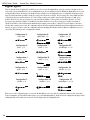
Pages 3, 4, and 5 of the Graphic EQ are all similar, each displaying the center frequencies available. Pages 3, 4, and 5 will look something
like this:
16
RP21D User’s Guide
4
FACTORY
USER
BANK
PAGE
OF
3 5
80Hz
1
140Hz 250Hz 450Hz
%kHz
msdB 2 0%kHz
3msdB 3
LINK CHANGED
LINK CHANGED
COMP
Section Two - Editing Functions
WAH
SEAMLESS
%kHz
2%kHz
msdB 4
msdB
LINK
TUBE
EQ
DIST
EQ
b
LINK
1
%kHz
%kHz
msdB
msdB
GATE
#
DIGITAL
CLIP
L/R OUTS
As in all other editing functions, the display is telling you that each parameter shown is accessable by using the 1-4 buttons which will select
the frequency corresponding to the 1-4 icons in the display. Once the frequency has been selected, rotating the Data Wheel will boost or cut
the gain applied to that frequency. The 10 Band Graphic EQ on the RP21D can be compared to having 10 tone knobs on an amplifer. Each
one adjusts a specific segment of the spectrum of frequencies that a guitar generates. The following list outlines the tonal range that each
frequency represents.
80 Hz
Low Bass Frequency
1.5 kHz
High Mid Range Frequency
140 Hz
Mid Bass Frequency
2.5 kHz
Low Treble Frequency
250 Hz
High Bass Frequency
4.5 kHz
Mid Treble Frequency
450 Hz
Low Mid Range Frequency
8 kHz
High Treble Frequency
800 Hz
Mid Range Frequency
15 kHz
Highest Treble Frequency
If you made any changes to the Graphic EQ parameters, you can save your changes to a user default for the Graphic EQ. This will allow you
to quickly recall all of these Equalizer settings when creating another Program just by choosing the user default. To save your Graphic EQ
settings to a user default, you will have to return to page 1 of 5, and the display will look something like this:
1
4
FACTORY
USER
BANK
PAGE
OF
1
5
1 On %kHz
msdB 2 LINK CHANGED
SEAMLESS
b
Custom Tube GEQ 10
%kHz
msdB
%kHz
3 Sto%kHz
msdB 4 --sdB
LINK CHANGED
COMP
WAH
LINK
TUBE
EQ
DIST
EQ
LINK
GATE
#
DIGITAL
CLIP
L/R OUTS
The number 3 icon is telling you that in order to store your EQ settings to a default, you must press the number 3 button. Once you press the
number 3 button, the RP21D will take you into a naming menu to give your EQ default setting a custom name. See page 21 for more
information on naming functions.
NOTE: The Store option for saving an EQ default will not appear if you did not make any changes to the EQ parameters.
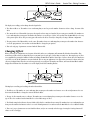
Noise Gate
A noise gate is an effect which prevents background noise from being heard while you are not playing. A noise gate has a threshold setting
which determines the strength or volume of the incoming signal required to open or close the gate. When your signal exceeds the
threshold, the gate will open allowing sound to be heard. When your signal falls below the threshold, the gate closes allowing nothing to
come through. The ideal setting for the threshold is to have it open as soon as you strike a string, and close when you stop playing. To
access the Noise Gate parameters, press the Preamp button until the Gate box is flashing. The display will look something like this:
17
RP21D User’s Guide
Section Two - Editing Functions
1
3
4
FACTORY
USER
BANK
PAGE
OF
1
3
2
Noise Gate
LINK CHANGED
LoThresh
%kHz
msdB
1 On %kHz
msdB 2 %kHz
msdB
LINK CHANGED
COMP
WAH
SEAMLESS
LINK
TUBE
EQ
DIST
EQ
b
4 F 1%kHz
msdB
LINK
GATE
#
DIGITAL
CLIP
L/R OUTS
The Display is now telling you three things about the Noise Gate
1. This is showing that the type of effect you are about to edit is the Noise Gate, and that the effect is on. The number 1 icon before the word
“on” indicates that in order to access the on/off parameter, you must press the number 1 button. The status can then be changed by
rotating the Data Wheel.
2. This is the default setting for the Noise Gate. The Noise Gate default shown here is factory default 1 (F1)which is a Low Threshold setting.
The number 4 icon which precedes the F1 value, indicates that in order to access the default parameter, you must press the number 4
button. The default can then be changed by rotating the Data Wheel. See page 22 for a complete list of defaults.
3. The bottom corner of the display is showing that there are 3 pages of parameters associated with the Noise Gate, and that you are on the
first of these three pages. The Next Page button can be used to access page 2 of the Noise Gate parameters.
Once you have accessed page 2 of the Noise Gate, the display will look something like this:
1
2
4
FACTORY
USER
BANK
PAGE
OF
2
3
Type:Silencer2
4%kHz
msdB 3 S
msdB 2
2 %kHz
1
LINK CHANGED
LINK CHANGED
COMP
WAH
SEAMLESS
LINK
TUBE
EQ
DIST
EQ
b
Post T&D
%kHz
msdB
%kHz
1to4
3msdB
LINK
GATE
#
DIGITAL
CLIP
L/R OUTS
1. This is the type of Noise Gate that you are going to use. You have two choices of Noise Gate types. The different types are basically
changing the plascement of the Gate in the signal path. Silencer 1 puts the Noise Gate detector at the input of the RP21D before the signal
enters the Preamp. Silencer 2 places the gate detector at the end of the Preamp after the Preamp modules. Silencer 2 is also more
sensitive to the signal that is present, and not as likely to shut while you are playing. Press the number one button and rotate the Data
Wheel to change the type of Gate.
2. This section of the display is showing that there are 3 pages of parameters associated with the Noise Gate, and that you are on the second
of these three pages. The Next Page button can be used to access page 3 of the Noise Gate parameters.
After you have accessed the third page of the Noise Gate parameters, the display will look something like this:
1
5
4
FACTORY
USER
BANK
PAGE
OF
3
3
4%kHz
msdB 3
%kHz
1 -60
msdB 2
LINK CHANGED
LINK CHANGED
COMP
WAH
LINK
TUBE
EQ
DIST
EQ
%kHz
msdB
1 4
LINK
%kHz
3msdB
GATE
#
DIGITAL
CLIP
The display it now telling you five more things about the Noise Gate parameters.
18
4
ThreshAtten AttackRelse
SEAMLESS
b
3
2
L/R OUTS
RP21D User’s Guide
Section Two - Editing Functions
1. This parameter is the Gate Threshold which adjusts the signal strength required to open or close the gate. The number 1 icon is telling
you that in order to access the GAte Threshold, you must press the number 1 button. You can then adjust the Gate Threshold by rotating
the Data Wheel.
2. This is the Attenuation parameter. Attenuation is the amount of cut applied to the signal when the Gate is closed. The number 2 icon is
telling you that in order to access the Attenuation parameter, you must press the number 2 button. You can then change the Attenuation
value by rotating the Data Wheel.
3. This is the Attack parameter. The Attack sets the length of time it takes for the gate to open once the Threshold has been exceeded. The
number 3 icon is telling you that in order to access the Attack parameter, you must press the number 3 button. You can then change the
Attack value by rotating the Data Wheel.
4. This is the Release parameter. The Release is the length of time the gate will remain open after the signal has fallen below the Threshold.
The number 4 icon is telling you that in order to access the Release parameter, you must press the number 4 button. You can then change
the Release value by rotating the Data Wheel.
5. This section of the display is telling you that you are on page 3 of 3. There are no more pages of parameters to display. Pressing the Next
Page button will wrap around to page 1 of 3.
If you made any changes to the Noise Gate parameters, you can save your changes to a user default for the Noise Gate. This will allow you to
quickly recall all of these Noise Gate settings when creating another Program just by choosing the user default. To save your Noise Gate
settings to a user default, you will have to return to page 1 of 2, and the display will look something like this:
1
4
FACTORY
USER
BANK
PAGE
OF
1
2
Noise Gate
1 On %kHz
msdB 2 LINK CHANGED
Custom
%kHz
msdB
%kHz
3 Sto%kHz
msdB 4
msdB
---
LINK CHANGED
COMP
WAH
SEAMLESS
LINK
TUBE
EQ
DIST
EQ
b
LINK
GATE
#
DIGITAL
CLIP
L/R OUTS
The number 3 icon is telling you that in order to store your Noise Gate settings to a default, you must press the number 3 button. Once you
press the number 3 button, the RP21D will take you into a naming menu to give your Noise Gate default setting a custom name. See page 21
for more information on naming functions.
NOTE: The Store option for saving a Noise Gate default will not appear if you did not make any changes to the Noise Gate parameters.
Master Preamp Settings
The Preamp includes some master settings that affect the function of the preamp as a whole. These setting include such parameters as
panning assingments for the Tube and Solid State Distortions, Mix settings, and independent volume levels for the active Distortions,
bypassed Distortions, DSP Levels, and Master Levels. To access the Master Preamp Settings, press the Preamp button until the entire Preamp
section is flashing. Then press the Next Page button until you are on page two. The Display looks something like this:
1
4
4
FACTORY
USER
BANK
PAGE
OF
2
4
TUBEPan
1
LINK CHANGED
SEAMLESS
b
DISTPan
%kHz
msdB 2 0
%kHz
msdB
3
LINK CHANGED
COMP
3
2
WAH
LINK
TUBE
EQ
DIST
EQ
Mix
%kHz
0%kHz
msdB 4 100 msdB
LINK
GATE
#
DIGITAL
CLIP
L/R OUTS
The display it now telling you four more things about the Master Preamp parameters.
1. This parameter is the Tube Distortion Pan. The pan is the left/right positioning of the Tube distortion. The number 1 icon is telling you
that in order to access the Tube Distortion Pan, you must press the number 1 button. You can then adjust the Pan of the Tube Distortion
by rotating the Data Wheel.
19
RP21D User’s Guide
Section Two - Editing Functions
2. This parameter is the Distortion Pan. The pan is the left/right positioning of the Distortion. The number 2 icon is telling you that in order
to access the Distortion Pan, you must press the number 2 button. You can then adjust the Pan of the Distortion by rotating the Data
Wheel.
3. This is the Mix parameter. It controls the overall strength of signal being fed into the digital effects from both distortion paths. The
number 4 icon indicates that in order to access the mix parameter, you must press the number 4 button. The mix parameter can then be
adjusted by rotating the Data Wheel.
4. This section of the display is telling you that there are four pages of Preamp parameters, and that you are currently on the second page.
Pressing the Next Page button will advance you to the third page of Preamp parameters.
Once you have accessed page 3 of the Preamp, the display will look something like this:
1
5
4
FACTORY
USER
BANK
PAGE
OF
3 4
2
3
4
Tube:On Lvl DSPLvl Mstr
%kHz
1 On%kHz
msdB 2 95 msdB 3
LINK CHANGED
LINK CHANGED
COMP
WAH
SEAMLESS
LINK
TUBE
EQ
DIST
EQ
b
%kHz
%kHz
%kHz
80%kHz
msdB
msdB
msdB 4 100
msdB
LINK
GATE
#
DIGITAL
CLIP
L/R OUTS
The display it now telling you five more things about the Preamp parameters.
1. This parameter is telling you that you are editing the parameters of the Tube distortion when it is on. You can also edit the bypassed
parameters of the Tube distortion. The number 1 icon is telling you that in order to access the status of editable Tube Distortion
parameters, you must press the number 1 button. You can then select the bypassed Tube Distortion parameters by rotating the Data
Wheel.
2. This is the Volume Level of the Tube Distortion. This parameter should be adjusted while watching the bar graph in the bottom of the
display. Use this parameter to prevent clipping from occuring. The number 2 icon is telling you that in order to access the Volume Level,
you must press the number 2 button. You can then change the Level value by rotating the Data Wheel.
3. This is the Volume Level of the Tube Distortion signal being fed into the digital section of the RP21D. Use this parameter to prevent digital
clipping from occuring. The number 3 icon is telling you that in order to access the Digital Level, you must press the number 3 button.
You can then change the Digital Level value by rotating the Data Wheel.
4. This is the combined Master Volume Level of the Program. Should digital clipping occur while using the Digital output, reduce this
parameter. The number 4 icon is telling you that in order to access the Master Level, you must press the number 4 button. You can then
change the Master Level value by rotating the Data Wheel.
5. This section of the display is telling you that there are four pages of Preamp parameters, and that you are currently on the third page.
Pressing the Next Page button will advance you to the fourth page of Preamp parameters.
Once you have accessed page 4 of the Preamp parameters, the display will look something like this:
1
5
4
FACTORY
USER
BANK
PAGE
OF
4 4
3
%kHz
%kHz
%kHz
%kHz
%kHz
%kHz
1 Byp
msdB 2 msdB
msdB 4 100
msdB
100 msdB 3 100msdB
LINK CHANGED
LINK CHANGED
COMP
WAH
LINK
TUBE
EQ
DIST
EQ
LINK
GATE
#
The display it now telling you five more things about the Preamp parameters.
20
4
Dist:BypLvl DSPLvl Mstr
SEAMLESS
b
2
DIGITAL
CLIP
L/R OUTS
RP21D User’s Guide
Section Two - Editing Functions
1. This parameter is telling you that you are editing the parameters of the Distortion when it is bypassed. You can also edit the on parameters
of the Distortion. The number 1 icon is telling you that in order to access the status of editable Distortion parameters, you must press the
number 1 button. You can then select the on Distortion parameters by rotating the Data Wheel.
2. This is the Volume Level of the Distortion. This parameter should be adjusted while watching the bar graph in the bottom of the display.
Use this parameter to prevent clipping from occuring The number 2 icon is telling you that in order to access the Volume Level, you must
press the number 2 button. You can then change the Level value by rotating the Data Wheel.
3. This is the Volume Level of the Distortion signal being fed into the digital section of the RP21D. Use this parameter to prevent digital
clipping from occuring. The number 3 icon is telling you that in order to access the Digital Level, you must press the number 3 button.
You can then change the Digital Level value by rotating the Data Wheel.
4. This is the combined Master Volume Level of the Program. Should digital clipping occur while using the Digital output, reduce this
parameter. The number 4 icon is telling you that in order to access the Master Level, you must press the number 4 button. You can then
change the Master Level value by rotating the Data Wheel.
5. This section of the display is telling you that you are on page 4 of 4. There are no more pages of parameters to display. Pressing the Next
Page button will wrap around to page 1 of 4.
Storing a User Preamp Default
You have now reached the end of the Preamp Effects. You can now save your settings of all the Preamp Effects to a Preamp Default. That way
you can quickly recall all of these settings in another Program without having to reProgram each individual Preamp Effect.
To store your preamp settings to a User Default, press the preamp button until the entire preamp section is flashing. The display will look
something like this:
1
2
4
FACTORY
USER
BANK
PAGE
OF
1
4
PreAmp:
1 %kHz
msdB
2
LINK CHANGED
Custom
%kHz
msdB
%kHz
3 Sto%kHz
msdB 4
msdB
---
LINK CHANGED
COMP
WAH
SEAMLESS
LINK
TUBE
EQ
DIST
EQ
b
LINK
GATE
#
DIGITAL
CLIP
L/R OUTS
The Display is now telling you two things about the Preamp Section.
1. The number 3 icon is telling you have made changes in the Preamp modules and that in order to store your Preamp settings to a default,
you must press the number 3 button. Once you press the number 3 button, the RP21D will take you into a naming menu to give your
Preamp default settings a custom name. See the following section for more information on naming functions.
2. The bottom corner of the display is showing that there are 4 pages of parameters associated with the Preamp section, and that you are on
the first of these two pages. The Next Page buttons can be used to access page 2 of the Preamp section.
Naming a Default
Every user default can be given a name that you choose. After you have chosen to store a custom default by pressing the number three button
from the default page, the RP21D will take you into a naming mode. The display will look something like this:
1
4
FACTORY
USER
BANK
PAGE
OF
3 4
Name:User 1
%kHz
%kHz
1 CAP
msdB 2 nbr msdB 3
LINK CHANGED
LINK CHANGED
COMP
SEAMLESS
WAH
LINK
TUBE
EQ
DIST
EQ
b
%kHz
%kHz
%kHz
%kHz
DeL
msdB
msdB
msdB 4 Ins
msdB
LINK
GATE
#
DIGITAL
CLIP
2
3
L/R OUTS
4
5
The display is now showing you 5 things that pertain to naming a default.
21
RP21D User’s Guide
Section Two - Editing Functions
1. This is the current name of the default. There will be a cursor under one of the characters of the name. This indicates which character
has been selected. Rotating the Data Wheel will change the character. The next and previous page buttons will move the cursor right or
left.
2. The number 1 icon is indicating that pressing the number 1 button will select a letter, change from upper case to lower case, or lower
case to upper case.
3. The number 2 icon is indicating that pressing the number 2 button will select a number.
4. The number 3 icon is indicating that pressing the number 3 button will select the delete function and will delete the characters to the left.
5. The number 4 icon is indicating that pressing the number 4 button will select insert and shift the characters to the right.
After your custom default name is showing in the display, press the Store button once. The display will ask which one of the user defaults you
wish to store the name and settings to. Use the Data Wheel to make your selection. Press the store button again, and
the Display will ask which of the User Programs you wish to store the settings to. Use the Data Wheel to make your selection. Once you have
selected the Program number that you want to store the settings to, press the Store button again. Your User Preamp Default has been saved.
To abort the naming function, press the Program button.
Default List
The Following is a list of Factory Preamp Defaults:
22
RP21D User’s Guide
Section Two - Editing Functions
23
RP21D User’s Guide
Section Two - Editing Functions
Digital Effects
There are literally dozens of digital effects available for you to choose from. The Digital Effects can be placed in any order that you choose,
and you may even run redundant effects. Up to four Digital Effects can be used simultaneously in the RP21D. The Digital Effects are accessed
by using the Effects button. The first press of the Effects button will take you to the Configuration page. A configuration determines how the
signal is routed from module to module, and the processing power allocated to each effect. The processing power of the S-DISC II modules
is divided into 4th power modules which use 25% of the total processing power available (represented by the number 4), HLF power
modules which use 50% of the processing power (represented by the number 2), three quarter power modules which use 75% of the
procesing (represented by the number 3), and FUL power modules which use 100% of the processing power. A full power module is
capable of much more control and fine tuned adjustments than a quarter power module is. A full power reverb for instance, will sound
smoother than a quarter power reverb. The configuration will also affect the way that the RP21D responds when morphing between the two
Preamps. See page 50 for more on how the configuration affects the morphing. The RP21D contains 15 different configurations for you to
choose from. The following is a list of configurations available.
Configuration 1
Configuration 6
Configuration 11
(Series -Full)
(Split Parallel- 2, 2)
(Parallel - 4, 4, 2)
L/R OUTS
Configuration 2
(Series - 3, 4)
L/R OUTS
L/R OUTS
L/R OUTS
L/R OUTS
Configuration 7
(Series - 4, 4, 2)
L/R OUTS
L/R OUTS
Configuration 12
(Parallel/Split - 4, 4, 2)
L/R OUTS
L/R OUTS
Configuration 3
Configuration 8
Configuration 13
(Series - 4, 3)
(Series - 2, 4, 4)
(Series - 4, 4, 4, 4)
L/R OUTS
L/R OUTS
L/R OUTS
L/R OUTS
Configuration 4
Configuration 9
Configuration 14
(Series - 2, 2)
(Series - 4, 2, 4)
(Parallel - 4, 4, 4, 4)
L/R OUTS
L/R OUTS
L/R OUTS
L/R OUTS
Configuration 5
Configuration 10
Configuration 15
(Parallel - 2, 2)
(Parallel - 4, 4, 2)
(Parallel/Split - 4, 4, 4, 4)
L/R OUTS
L/R OUTS
L/R OUTS
L/R OUTS
When you access the configuration page, you can rotate the Data Wheel to select one of the 15 configurations. Once you have selected the
desired configuration, press the Effects button again to access and edit the Digital Effects. The first box in the configuration will begin to flash
indicating that this is the module you are about to edit. The display may look something like this:
24
RP21D User’s Guide
1
4
4
FACTORY
USER
BANK
PAGE
OF
1
1
2
3
FX:Thru Module
%kHz
1 On %kHz
2 4thmsdB
msdB 2
LINK CHANGED
WAH
SEAMLESS
TUBE
EQ
DIST
EQ
b
Center
%kHz
msdB
LINK CHANGED
COMP
Section Two - Editing Functions
LINK
4 F 1%kHz
msdB
LINK
GATE
#
DIGITAL
CLIP
L/R OUTS
The display is now telling you four things about the digital effect.
1. The effect module is on. The number 1 icon is indicating that you need to press the number 1 button in order to change the status of the
effect.
2. The current effect is a Thru module (just passes dry signal) and it is using one fourth of the processing power available. The number two
icon is indicating that you must press the number two button to access the type of effect. You can then rotate the Data Wheel to select any
of the quarter power effects. The processing power allocated to the effects can only be changed by selecting a different configuration.
3. The pan position of the Thru module is in the center. The number four icon is indicating that you must press the number four button to
access the pan parameter. You can then use the Data Wheel to change the pan position.
4. This is the only page of parameters associated with the Thru module.
Changing Effects
When you change the configuration on a Program, all modules in the new configuration will automatically default as thru modules. This
means that you will not have any digital effects processing until you select the type of effects that you want to use. Choosing the type of effect
is accomplished by pressing the number 2 button and rotating the Data Wheel until the desired type of effect is shown above the number two
icon. Then you can edit the parameters associated with the effect to suit your application. Let’s suppose that you wanted a chorus as the first
effect in your digital chain. From the screen shown previously, you would press the number two button, and rotate the Data Wheel until the
display showed Chorus above the number 2 icon. The display would look something like this:
1
4
4
FACTORY
USER
BANK
PAGE
OF
1
5
2
3
FX: Dual Cho
Medium
%kHz
1 On %kHz
2 4thmsdB
msdB 2
LINK CHANGED
%kHz
msdB
LINK CHANGED
COMP
SEAMLESS
b
WAH
TUBE
EQ
DIST
EQ
LINK
4 F 1%kHz
msdB
LINK
GATE
#
DIGITAL
CLIP
L/R OUTS
The Display is now telling you four things about the Chorus Effect.
1. The Effect is on. The number one icon is indicating that you must press the number one button to access the on/off parameter. You can
then rotate the Data Wheel to change the status of the Chorus Effect.
2. The type of effect currently active is a Chorus. The number two icon is indicating that you must press the number 2 button to access the
type of effect. You can then rotate the Data Wheel to select a different type of effect.
3. The default setting for the Chorus is Factory default 1 (F1) which is a medium chorus setting. The number four icon is indicating that you
must press the number four button in order to access the default parameter. You can then rotate the Data Wheel to select a different default.
4. There are 5 pages of parameters associated with the Chorus, and you are currently on the first page. Pressing the Next Page button will
advance to the second page.
25
RP21D User’s Guide
Section Two - Editing Functions
Once the second page of parameters has been accessed, the display will look something like this:
1
4
4
FACTORY
USER
BANK
PAGE
OF
2
5
2
FX:Lvl
Dry:Lvl Balance
%kHz
msdB
1 50 %kHz
2 msdB 2
LINK CHANGED
3 100%kHz
msdB 4
LINK CHANGED
COMP
3
WAH
SEAMLESS
LINK
TUBE
EQ
DIST
EQ
b
LINK
0
%kHz
msdB
GATE
#
DIGITAL
CLIP
L/R OUTS
The display is now telling you four more things about the Chorus parameters.
1. This is the input level of the Chorus effect. The number one icon is indicating that you must press the number one button to access the
effect level parameter. You can then rotate the Data Wheel to change the value of the effect level.
2. This is the level of the Dry signal being mixed in with the Chorus effect. The number three icon is indicating that you must press the
number three button to access the Dry level parameter. You can then rotate the Data Wheel to change the value of the Dry level.
3. This is the left/right Balance parameter of the Chorus effect. The number four icon is indicating that you must press the number four
button to access the Balance parameter. You can then rotate the Data Wheel to change the value of the Balance.
4. There are 5 pages of parameters associated with the Chorus, and you are currently on the second page. Pressing the Next Page button will
advance to the third page.
Once the third page of parameters has been accessed, the display will look something like this:
1
4
4
FACTORY
USER
BANK
PAGE
OF
3 5
3
Speed Depth
1 0.30
22 4
.0
WvFrm
%kHz
msdB
%kHz
msdB
LINK CHANGED
SEAMLESS
b
2
%kHz
%kHz
3 100o
msdB 4 Sin msdB
LINK CHANGED
COMP
WAH
TUBE
EQ
DIST
EQ
LINK
LINK
GATE
#
DIGITAL
CLIP
L/R OUTS
The display is now telling you four more things about the Chorus parameters.
1. This is the Speed of the Chorus effect. The number one icon is indicating that you must press the number one button to access the Speed
parameter. You can then rotate the Data Wheel to change the value of the Speed.
2. This is the Depth of the Chorus effect. The number two icon is indicating that you must press the number two button to access the Depth
parameter. You can then rotate the Data Wheel to change the value of the Depth.
3. This is the Wave Form parameter of the Chorus effect. The number four icon is indicating that you must press the number four button to
access the Wave Form parameter. You can then rotate the Data Wheel to select a different Wave Form.
4. There are 5 pages of parameters associated with the Chorus, and you are currently on the third page. Pressing the Next Page button will
advance to the fourth page.
Once the fourth page of parameters has been accessed, the display will look something like this:
26
RP21D User’s Guide
1
3
4
FACTORY
USER
BANK
PAGE
OF
4 5
Section Two - Editing Functions
2
DlyA
DlyB Balance
1 50 %kHz
2 msdB 2
LINK CHANGED
%kHz
msdB
3 100%kHz
msdB 4
LINK CHANGED
COMP
WAH
SEAMLESS
LINK
TUBE
EQ
DIST
EQ
b
LINK
0
%kHz
msdB
GATE
#
DIGITAL
CLIP
L/R OUTS
The display is now telling you three more things about the Chorus parameters.
1. The Dual Chorus has two delay circuits. This is the delay time of the first delay in the Chorus effect. The number one icon is indicating that
you must press the number one button to access the Delay A parameter. You can then rotate the Data Wheel to change the Delay time of
the first Delay.
2. This is the delay time of the second delay in the Chorus effect. The number three icon is indicating that you must press the number three
button to access the Delay B parameter. You can then rotate the Data Wheel to change the Delay time of the second Delay.
4. There are 5 pages of parameters associated with the Chorus, and you are currently on the fourth page. Pressing the Next Page button will
advance to the fifth page.
Once the fifth page of parameters has been accessed, the display will look something like this:
5
4
FACTORY
USER
BANK
PAGE
OF
5
5
1
2
3
4
OutA
PanA
OutB
PanB
%kHz
%kHz
%kHz
1 100%kHz
2 L99msdB 3 100msdB 4 r99 msdB
msdB 2
LINK CHANGED
SEAMLESS
b
LINK CHANGED
COMP
WAH
LINK
TUBE
EQ
DIST
EQ
LINK
GATE
#
DIGITAL
CLIP
L/R OUTS
The display is now telling you five more things about the Chorus parameters.
1. This is the Output Level of the first Chorus circuit in the Dual Chorus effect. The number one icon is indicating that you must press the
number one button to access the Output Level A parameter. You can then rotate the Data Wheel to change the Output Level of the first
Chorus circuit.
2. This is the Pan position of the first Chorus circuit in the Dual Chorus effect. The number two icon is indicating that you must press the
number two button to access the Pan A parameter. You can then rotate the Data Wheel to change the Pan position of the first Chorus
circuit.
3. This is the Output Level of the second Chorus circuit in the Dual Chorus effect. The number three icon is indicating that you must press
the number three button to access the Output Level B parameter. You can then rotate the Data Wheel to change the Output Level of the
second Chorus circuit.
4. This is the Pan position of the second Chorus circuit in the Dual Chorus effect. The number four icon is indicating that you must press the
number four button to access the Pan B parameter. You can then rotate the Data Wheel to change the Pan position of the second Chorus
circuit.
5. There are 5 pages of parameters associated with the Chorus, and you are currently on the fifth page. There are no more parameters
associated with the Chorus effect. Pressing the Next Page button will return to the first page.
Like the Preamp effects, every Digital effect includes user defaults which can hold your favorite settings for quick recall. The procedure for
storing defaults to the Digital effects is the same as for the Preamp effects defaults. See page 21 for more information on storing a default to
an effect.
27
RP21D User’s Guide
Section Two - Editing Functions
Effect Types
Pressing the Effects button will advance you to the next module in the Digital Effect chain. The procedure for editing each module will be
the same as the procedure previously described with the chorus. The only exception being that different effects will have different
parameters, and some may have a different number of pages. The following is a list of the types of effects available with the RP21D, and a
definition of the parameters.
Choruses and Flangers
Both choruses and flangers use a Low Frequency Oscillator (LFO) to produce their rich, swirling effects. When you change the speed and
depth Parameters of modulation effects, you're actually controlling the frequency and amplitude of the LFO. These settings determine the rate
and intensity of the modulation effect.
5 cents
0
-5 cents
10
P I T C H
10
In general, here's how a chorus works: after entering the Module, the source signal is split into two paths. One is allowed to pass through
the Module unaltered, while the other is delayed and pitch modulated with an LFO. The modified sound is then sent to the output, along
with the original. In the following figure, a sine wave is used to modulate the pitch of the split sound source. The Dual Chorus creates two
different pitch “voices”, while the Octal Chorus creates eight voices for extremely full, rich sounds.
1 sec
2 sec
3 sec
Modulated Sound
Original Sound
T I M E
The only difference between choruses and flangers is that flangers use less delay and have a feedback Parameter that sends a portion of the
effected signal back to the input of the selected module. When the effected signal reaches the input, it is sent through the Module again,
building thickness and depth. If you increase the feedback enough, the source begins to lose its own original pitch to the dramatic pitch
modulation of the feedback loop.
SINE LFO
SP1 LFO
FREQUENCY (SPEED)
SP2 LFO
AMPLITUDE (DEPTH)
FREQUENCY (SPEED)
AMPLITUDE (DEPTH)
FREQUENCY (SPEED)
TRIANGLE LFO
AMPLITUDE (DEPTH)
FREQUENCY (SPEED)
AMPLITUDE (DEPTH)
AMPLITUDE (DEPTH)
LFO Waveforms: There are four LFO waveforms available for Choruses, Flangers, Phasers, Tremolos, Auto Panners. They include SINe,
TRIangle, SPecial-1, SPecial-2, and SPecial-3. The following examples show what these waveforms look like.
FREQUENCY (SPEED)
SP3 LFO
(Modifiers only)
Chorus
Chorus is probably the most basic modulation effect. It is really just a very small delay whose time is always changing. As the time is varied,
the delayed signal's pitch changes (just like a tape recordings pitch raises when you play it faster). By moving the time back and forth, you
hear a sound that goes in and out of tune. When combined with the original sound, it almost sounds like more than one instrument is
playing. The RP21D uses several choruses at once to make huge rich sounds. For example, the octal chorus uses eight chorus voices at once
28
RP21D User’s Guide
Section Two - Editing Functions
to create an incredible ensemble of sound. Aside from the more obvious speed and depth parameters (which adjust respectively how fast
and far the sound goes out of tune), the RP21D allows you to use different waveforms. The waveform defines how it will move in and out of
tune. The triangle waveform is very popular for slow, shallow chorus settings, while the sine waveform works nicely for faster, deeper
settings.
When do I use Chorus? The Chorus effect is so vast in applications, an easier question would probably be “When can’t I use a
Chorus. When playing the Blues, turn the Speed and Depth parameters up to produce an almost Leslie-Type effect When trying to obtain
“Big” rock guitar tone, use the Chorus to thicken-up and add depth to your sound. And, any time your using a clean tone Program, the
guitar is always much more lush sounding when Chorus is added.
Chorus Parameters:
Note: not all parameters listed below are available in all Chorus modules.
FX: Lvl
Controls the signal input level fed to the module. Ranges from Off to 100%.
Dry: Lvl
Controls the level of the dry (uneffected) signal. Ranges from Off to 100%.
Balance
Controls the left/right positioning of the dry signal in the stereo soundfield. Ranges from -99 (all left) to 99 (all
right).
Speed
Controls the Low Frequency Oscillator (LFO) speed of the chorus. Ranges from 0.06 to 16.0 Hz.
Depth
Adjusts the intensity of the chorus effect. High settings produce dramatic modulation, while lower settings can be
used to produce a more subtle, ambient swirling. Ranges from 0 to 30 milliseconds.
Depth 1 - 2
DEPTH1 adjusts the intensity of chorus voices 1-4. DEPTH2 adjusts the intensity of chorus voices 5-8. Ranges from 0
to 30 milliseconds.
Wander Speed
Controls the secondary LFO speed of chorus voices 5-8. This is a secondary oscillator for voices 5-8 that causes
deviations from the oscillation path set by DEPTH2. This control can produce radical new textures when used
creatively. Try setting it slightly faster or slower than SPEED. Ranges from 0.06 to 2.0 Hz.
Wander Depth
Adjusts the intensity of the oscillation deviations produced by WANDER SPEED. WANDER DEPTH produces dramatic
psycho-acoustic swirling effects when set higher than DEPTH2. Ranges from 0 to 10 milliseconds.
WvFrm
Selects which waveform the LFO follows. Options: sine, triangle, SP1 (special 1), and SP2 (special 2). See figure 3-4
Dly A - B
Controls the delay time of chorus voices A and B. Higher delay time settings produce a more dramatic sweeping
sound. Ranges from 0 to 60 milliseconds.
Dly C - D
Controls the delay time of chorus voices C and D. Higher delay time settings produce a more dramatic sweeping
sound. Ranges from 0 to 60 milliseconds
Dly E - H
Controls the delay time of chorus voices E through H. Higher delay time settings produce a more dramatic sweeping
sound. Ranges from 0 to 60 milliseconds
Out A - B
Adjusts the overall level of chorus voice A or B. Ranges from Off to 100%.
29
RP21D User’s Guide
Section Two - Editing Functions
Pan A - B
Controls the placement of chorus voice A or B. Ranges from -99 to 99.
Out C - D
Adjusts the overall level of chorus voice C or D. Ranges from Off to 100%.
Pan C - D
Controls the placement of chorus voice C or D in the stereo image. Ranges from -99 to 99.
Out LA - LB
Adjusts the left-side level of chorus voice A or B. Ranges from Off to 100%.
Out RA - RB
Adjusts the right-side level of chorus voice A or B. Ranges from Off to 100%.
Spread
Controls the width of the effect’s stereo imaging. The higher the setting, the wider the image. The lower the setting,
the more monophonic the effect becomes. Ranges from 1 to 10.
Flanger
A flanger is just a chorus that loops back into itself, causing what can be described as a tubular sound (since it sounds much like the
reflections heard inside a large cement or metal pipe). It is still a modulating effect, so you hear a lot of sweeping movement. This makes the
flanger a very colorful effect that can be easily overused if you're not careful. The more you feed the flanger back to itself, the more intense
the sound becomes.
When do I use Flanger? An electric guitar is the first sound that begs for the flanger effect. It works very well with both clean and
distorted guitar sounds. By setting the Speed and Depth parameters to higher settings, this will add more depth and body to the overall
guitar signal.
Flanger Parameters
Note: Not all of of the parameter listed below are available in all of the Flanger modules.
FX: Lvl
Controls the signal input level fed to the Module. Ranges from Off to 100%.
Dry: Lvl
Controls the level of the dry (uneffected) signal. Ranges from Off to 100%.
Balance
Controls the positioning of the dry signal in the stereo soundfield. Ranges from -99 (all left) to 99 (all right).
Speed
Controls the Low Frequency Oscillator (LFO) speed of the flanger. Ranges from 0.06 to 16.0 Hz.
Depth
Controls the intensity of the flange effect. High settings of DEPTH combined with high settings of FDBCK produce
dramatic, synth-like textures. Ranges from 0 to 30 milliseconds.
FdBck
Controls how much of the flanged signal is fed back to the input of the Module. The FDBACK Parameter is what gives
flangers their distinctive voice. Flangers are capable of both positive and negative feedback loops, so experiment to
find the sound you like best. Ranges from -99% to 99%.
Selects which waveform the LFO follows. Options for this control include sine, triangle, SP1 (Special 1), and SP2
(Special 2). The sine wave setting is probably the most easily recognized, but the smooth response of the triangle
wave or the intensity of SP1 or SP2 typically produce better results. See figure 4-2.
WvFrm
Dly A - B
30
Controls the delay time of flange voice A or B. Shorter delay times produce a more dramatic, deeper sweeping
sound. Ranges from 0 to 60 milliseconds.
RP21D User’s Guide
Section Two - Editing Functions
Out A - B
Adjusts the overall level of flange voice A or B. Ranges from Off to 100%.
Pan A - B
Controls the stereo soundfield placement of flange voice A or B. Ranges from -99 to 99.
Out L - R
Controls the output level of the left or right side of the flanger. Ranges from Off to 100%.
Phasers
The Phaser or “Phase Shifter” as it is sometimes called, is a classic effect from the 70's that uses phase cancellation to create a warm
sweeping effect. The effect is created by making a copy of a signal and moving it in and out of phase while mixing it with the original signal.
As it moves, different frequencies are cancelled out creating a smooth curling sound. There is also a feedback control that sends the shifting
signal back into the phaser's input. This intensifies the sound even more.
When do I use a Phaser? A great example of this can be heard most when you listen to music of the 70’s. Guitarist of the day loved
their Phasers. A Phaser is a great effect to use when playing clean and funky rhythms.
Phaser Parameters:
Dry: Lvl
Controls the level of the dry (uneffected) signal. Ranges from Off to 100%.
Balance
Controls the positioning of the dry signal in the stereo soundfield. Ranges from -99 (all left) to 99 (all right).
Speed
Controls the Low Frequency Oscillator (LFO) speed of the phaser. Ranges from 0.06 to 16.0 Hz.
Depth
Controls the intensity of the phaser effect. High settings of DEPTH combined with high settings of FDBCK produce
dramatic, synth-like textures. Ranges from 0 to 30 milliseconds.
FdBck
Controls how much of the flanged signal is fed back to the input of the Module. The FDBACK Parameter is what gives
phasers their distinctive resonating sound. Ranges from -99% to 99%.
WvFrm
Selects which waveform the LFO follows. Options for this control include sine, triangle, SP1 (Special 1), and SP2
(Special 2). The sine wave setting is probably the most easily recognized, but the smooth response of the triangle
wave or the intensity of SP1 or SP2 typically produce better results. See figure 4-2.
Out A - B
Adjusts the overall level of phaser voice A or B. Ranges from Off to 100%.
Pan A - B
Controls the stereo soundfield placement of phaser voice A or B. Ranges from -99 to 99.
Out L - R
Controls the output level of the left or right side of the flanger. Ranges from Off to 100%.
Pedal Phaser
The Pedal phaser is a phaser that can be controlled by an expression pedal to control the depth and feedback of the effect
Pedal Phaser Parameters
FX and Dry Level
Controls the FX and Dry level of the Pedal Phaser module. Ranges from Off to 100%.
Balance
Sets the Balance of the effect. Ranges from L 100 to R 100.
Pedal
This parameter is used to be controlled by the expression pedal to control Depth and Feedback. Range: 0 to 100.
31
RP21D User’s Guide
Section Two - Editing Functions
Depth
This parameter controls the amount of modulation depth in the phaser. Range is 0 to 100%.
Feedback
This parameter controls amount of feedback in the phaser effect. Range is 0 to 100%.
Output A-B
This parameter sets output of the pedal phaser effect. Range is from 0 to 100%.
Pan A-B
This parameter sets pan of the pedal Phaser Range is from 0 to 100%.
Rotary Speaker Simulator
The Rotary Speaker Simulator allows you to emulate the classic rotating speaker sound, without the chiropractic problems that come with
moving bulky speaker cabinets. The Rotary speaker is directly responsible for some of the most unique sounds in music. The applications
for this effect are so diverse, it can be used to achieve sounds ranging from the Allman Brothers Band to the legendary Stevie Ray Vaughan.
A unique parameter in the Rotating Speaker simulation is the Acceleration parameter. This parameter is used emulate the the time that it
takes to get the Speaker up and spinning at full speed. The parameter can be assigned to a footswitch or the expression pedal so you can
control the acceleration speed.
Rotary Speaker Simulator Parameters:
FX: Lvl
Controls the signal input level fed to the Module. Ranges from Off to 100%.
Dry: Lvl
Controls the level of the dry (uneffected) signal. Ranges from Off to 100%.
Balance
Controls the positioning of the dry signal in the stereo soundfield. Ranges from -99 (all left) to 99 (all right)
Mode
Selects which speed mode the Rotor and Horn are in. Settings are fast or slow.
Spread
Sets the horn stereo microphone spread. Ranges from 0 to 100%.
H - R: Level
Sets the overall level of the Rotor or Horn. Ranges from Off to 100%.
Slo - Fast Hrn Speed Controls the Low Frequency Oscillator (LFO) speed of the Horn. Ranges from 0.06 to 16.0 Hz.
Slo - Fast Hrn Depth Controls the intensity of the rotating effect. Ranges from 0 to 30 milliseconds.
Slo - Fast Hrn Doppler Sets the amount of shifted pitch heard in the Horn. Ranges from 0 to 50 milliseconds.
Slo - Fast Rtr Speed Controls the Low Frequency Oscillator (LFO) speed of the Rotor. Ranges from 0.06 to 16.0 Hz.
Slo - Fast Rtr Depth Controls the intensity of the rotating effect. Ranges from 0 to 30 milliseconds.
X-Over
Selects the frequency where the signal is split between the Horn and Rotor. Ranges from 25Hz to 20kHz.
Acceleration: H - R Sets the amount of time that the Rotor and Horn take to come up to their full rotating speed. Ranges from 0 to 10
seconds.
Tremolo and Auto-Panner
Look out, because the popular Tremolo and Auto panner effects of the 50’s and 60’s are back with a vengeance. These effects that revolutionized “Surf-Style” music can be heard all over the air waves in the 90’s. Tremolos and auto panners are similar to one another in that they
both use an LFO to modulate input levels to produce vibrato effects.
32
RP21D User’s Guide
Section Two - Editing Functions
Tremolo
The word tremolo actually has several definitions in the music world. It basically means that a sound is being modulated in amplitude (the
volume is beating or pulsing). It could be emulated by turning a volume knob up and down. But you probably have better things to do than
turn a volume control up and down throughout a whole song, so let the RP21D do it for you.
Aside from speed and depth parameters, the tremolo also has an LFO waveform that determines the way a signal's volume is increased and
decreased. While the Sine wave is probably the most common to the ear, the Triangle and Special 2 waveforms are progressively more
intense.
When do I use Tremolo? Tremolo is truly a vintage sound for the guitar, electric piano and organ. Most pronounced on the guitar, you
can hear it used on everything from sweet ballads to blues rock 'n roll.
Auto Panner
The auto panner is really just a dual version of a tremolo. It changes the amplitude of the left signal just as a tremolo does, but the amplitude
of the right signal is inverse to that of the left signal. This gives the illusion that the signal is moving back and forth between the left and right
speakers.
The Auto Panner's Speed typically doesn't get set as fast as the Tremolo since you usually want a sound to move smoothly back and forth in
the stereo image. The RP21D auto panner is especially flexible since it can be used for either mono or stereo input sources. When used with
a mono source, the signal pans back and forth as described earlier. When a stereo sound source is used, the original stereo image is
maintained by moving the volume of the left signal exactly opposite of the right signal. The stereo image fades back and forth between the
stereo extremes.
When do I use an auto panner? The auto panner can be a very creative tool. When running your guitar rig in a stereo set-up with the
right amount of cabinet separation, the Auto-Panner creates a stereo panning effect that is right out of this world.
Auto panners can also add life to delays or choruses by moving them around instead of just sitting in one place in the mix. Simply place an
auto panner module after a delay or chorus module. You don't need to set the auto panner's depth parameter too deep since you just
want some gentle movement.
Tremolo & Auto Panner Parameters:
FX: Lvl
Controls the signal input level fed to the Module. Ranges from Off to 100%.
Speed
Controls the Low Frequency Oscillator (LFO) speed of the effect. Ranges from 0.06 to 16.0 Hz.
Depth
Controls the intensity of the effect. As DEPTH increases, volume changes become more dramatic. Ranges from 0 to
30 milliseconds.
WvFrm
Selects which waveform the LFO follows. Options for this control include sine, triangle, SP1 (Special 1), and SP2
(Special 2). The sine wave setting is probably the most easily recognized, but the smooth response of the triangle
wave or the intensity of SP1 or SP2 typically produce better results. See figure 4-2 on page 41.
Delays
A delay produces discrete, repeating echoes of the source material at a specified interval. In digital delays, the input signal is "sampled" or
recorded into memory, where it is held for the amount of time you specify with the delay time setting, after which the sample is replayed at
the output. The RP21D delays have a feedback meter that is used to send a portion of the delayed signal back to the input to be re-recorded
along with new source material. The feedback setting determines how long the delay repeats take to decay to inaudibility.
33
RP21D User’s Guide
Section Two - Editing Functions
When do I use delay? When you’re the lone guitarist in a band, the Delay can be your best friend. The Delay repeats can create the
illusion that there is more than one guitar being played. One trick to using delays effectively is setting the delays to fall in time with the
music. This used to mean grabbing a calculator, dividing 60 by the tempo (beats per minute), then dividing that answer by the desired
sub-beats . . . Sound like a hassle? Yeah, we thought so too. So the RP21D takes care of all the calculations for you! All you have to do is
tap the TapIt (assign the tapit parameter to a footswitch) and manually tap in the desired delay time and the new time is added.
Another common use for delay is for stereo imaging. Very small amounts of delay (10-25ms) can be used to make a signal sound like it is
panned to one side. This trick works because of the way the brain interprets sounds. When your left ear hears something before the right
ear, it thinks that the source of that sound is found somewhere to your left. You can also use delays set at 30-60ms, which spreads a sound
to the extremes of the stereo image. Be careful with this technique if your mix has a chance of being listened to in mono.
Delay Parameters
Note: not all of the parameters listed below are available in all Delay modules.
34
FX: Lvl
Controls the signal input level fed to the Module. Ranges from Off to 100%.
Dry: Lvl
Controls the level of the dry (uneffected) signal. Ranges from Off to 100%.
Balance
Controls the positioning of the dry signal in the stereo soundfield. Ranges from -99 (all left) to 99 (all right).
Dly Time
Sets the maximum delay time available to each delay voice. For example, if DELAYTIME is set to 1000 ms, each delay
voice can be set from 0 to 100% of that delay time. Ranges from 0 to 1.4 seconds (Maximum delay times differ
between 4th, 3/4, HLF, and FUL module Types.) Half bandwidth delay times automatically double the set delay time
used used.
FdBck
Controls the fade time of the delay repeats. Higher settings take longer to fade out, while a setting of zero could be
used to limit the delay to one repeat per voice. The delay provide both positive and negative feedback settings.
Ranges from -99% to +99%.
TapIt
Allows you to change DELAYTIME in real-time, by tapping the TAPIT button at the tempo you want. Delay voice
percentages do not change when using this control.
Smear
Sets the spread of Diffusion of the Delay Repeats. Ranges from 0 to 100%.
LPF
Selects where the Low Pass Filter is positioned within the Delay Module. Positions are: Pre Delay or Post Delay.
Frequency
Selects the Frequency band that appears in the LPF. Ranges from 25 Hz to 20 kHz.
Gain
Dly A - B
Controls the output gain of the LPF. Ranges from -12 to 12.
Controls the percentage of DELAYTIME allocated to delay voices A and B. For example, if DELAYTIME (above) is set
to 1000 ms and DLYA is set to 75%, the voice A delay time is 750 ms. Remember, each voice in the Module can have
any delay time up to 100% of DELAYTIME. Ranges from 0% to 100%.
Dly C - D
See Dly A - B.
Out
Adjusts the overall level of the Delay. Ranges from Off to 100%.
RP21D User’s Guide
Section Two - Editing Functions
Pan
Controls the stereo soundfield placement of the delay. Ranges from -99 (all left) to 99 (all right).
Out L - R
Adjusts the left or right output level of the Delay. Ranges from Off to 100%.
Out A - B
Adjusts the output level of delay voice A or B. Ranges from Off to 100%.
Pan A - B
Controls the stereo soundfield placement of delay voice A or B. Ranges from -99 (all left) to 99 (all right).
Out C - D
Adjusts the output level of delay voice C or D. Ranges from Off to 100%.
Pan C - D
Controls the stereo soundfield placement of delay voice C or D. Ranges from -99 (all left) to 99 (all right).
Out LA - LB
Adjusts the left-side output level of delay voice A or B. Ranges from Off to 100%.
Out RA - RB
Adjusts the right-side output level of delay voice A or B. Ranges from Off to 100%.
Out LC - LD
Adjusts the left-side output level of delay voice C or D. Ranges from Off to 100%.
Out RC - RD
Adjusts the right-side output level of delay voice C or D. Ranges from Off to 100%.
Multi Effects Modules - Chorus/Delay and Flange/Delay
The RP21D Multi Effect Modules allow the User to combine either Delay and Chorus or Delay and Flange within one Effect module block.
This is ideal for situations where the User needs to add another effect to the Effect Configuration, but is running low on signal processing
resources. Within the module, there is a unique parameter that allows you route the signal several different ways between the two effects.
Multi-Effect Module Parameters
FX: Lvl
Controls the signal input level fed to the Module. Ranges from Off to 100%.
Dry: Lvl
Controls the level of the dry (uneffected) signal. Ranges from Off to 100%.
Balance
Controls the positioning of the dry signal in the stereo soundfield. Ranges from -99 (all left) to 99 (all right).
Route
Selects the route signal path within the Chorus/Delay, and Flange/Delay Multi effects modules. The 3 settings are: 1)
Chorus/Flange into Delay with feedback into the Delay 2) Chorus/Flange into Delay with feedback into Chorus/Flange
3) Delay into Chorus/Flange with feedback thru the Chorus/Flange.
Speed
Controls the Low Frequency Oscillator (LFO) Speed of the Chorus or Flanger. Ranges from 0.06 to 16.0 Hz.
Depth
Adjusts the intensity of the Chorus or Flanger effect. Ranges from 0 to 30 milliseconds.
Feedback (Flanger) Controls how much of the flanged signal is fed back to the input of the Module. The FDBACK Parameter is what gives
flangers their distinctive voice. Flangers are capable of both positive and negative feedback loops, so experiment to
find the sound you like best. Ranges from -99% to 99%.
WvFrm
Selects which waveform the LFO follow. Options for this control include: Sine, Triangle, SP1 (Special 1), and SP2
(Special 2).
35
RP21D User’s Guide
Section Two - Editing Functions
C/F: Delay
Controls the delay time of the Chorus or Flanger voice. Ranges from 0 to 40 milliseconds.
Delay Time
Sets the delay time for the delay tap. Ranges from 0 to 300 milliseconds.
Feedback
Controls the fade time of the delay repeats. Higher settings take longer to fade out, while a setting of zero will limit
the delay to one repeat. Ranges from 0 to 99%.
Allows you to change the Delay time in real-time by tapping the TAPIT button at the tempo you want. Delay voice
percentages do not change when using this control.
TapIt
Level: C/F/D
Controls the overall output level of each effect block. Ranges from Off to 100%.
Pan: C/F/D
Controls the stereo soundfield placement of each effect block. Ranges from -99 (all left) to 99 (all right).
Reverse Delay
A reverse delay is an echo effect which records the incoming signal, and then repeats it backwards. This effect is similar to the backwards
masking effect done in recording studios. This is where a guitar was recorded on to tape and then played backwards while being mixed
back in to the music.
On/Off
Selects whether the effect is active, or bypassed.
FX Level
Controls the volume level of the reverse delay signal. Ranges from off to 100%
Dry Level
Controls the volume level of the incoming source signal, or the signal that has no reverse delay effect. Ranges
from off to 100%
Balance
Controls the left/right placement of the reversed signal in the stereo field. Ranges from l-99 (full left) to r-99 (full
right) 0 is centered.
Reverse Time
This parameter adjusts the length of time for which the effect will record. Range is dependent upon the processing
power assigned to the module (5 seconds maximum with full power module).
Time Warp
Time warp is an interesting effect that records the incoming signal in to the delay, has the ability to then slow it down, and then play it back
in reverse. It sounds similar to hitting the stop button on a multi-track recorder, and you hear the sound slow down as the reels slowly stop
turning, and then the passage plays backwards.
On/Off
Controls whether the time warp effect is active, or bypassed.
FX Level
Controls the volume of the time warped sound. Range is from off to 100%.
Dry Level
Controls the volume of the original uneffected signal. Range is from off to 100%.
Amount
Adjusts the amount that the signal is warped or slowed down. Range is from off to 100%. 0-50 creates a tape stop
effect. 51-100 creates a tape start effect in reverse.
Warp Time
This is the length of time that the effect will record an incoming signal. Range depends upon the size of the
selected module.
Out L
Volume control for the left output. Range is from off to100%.
Out R
Volume control for the right output. Range is from off to100%.
Sampler
A sampler will record a musical passage, or riff. It will then trigger, or repeat it on your demand. Samples can be layered (one sample
stacked on top of another), and may put in loop mode (where they continue to repeat automatically).
On/Off
36
Controls whether the sampler effect is active, or bypassed.
RP21D User’s Guide
Section Two - Editing Functions
Loop
This parameter will engage, or disengage the loop function. With the loop function engaged, the sampled signal
will automatically continue to repeat. Range on and off.
Over Dub
This parameter allows you to play one passage in to the sampler, and then layer another passage over the top of
the first one. In other words, the two samples will combine. Ranges on and off.
RecPB
This selects whether the sampler is about to record a sample, or playback the existing sample. When no sample
has been recorded, this will default automatically to the record mode. After a sample has been recorded, it will
default to playback mode. Range record and playback.
Trig
This is the trigger parameter. Every time that the trig parameter is adjusted, it will repeat the recorded sample
from the beginning.
Start Time
This parameter allows you to trim the beginning of the sample. If for instance the recorded sample has an
undesired pause or noise at the beginning of it, the start time may be used to remove this from the sample. Range
varies depending on the size of the module.
End Time
This parameter allows you to trim off the end of the sample. If the sample had recorded more than you wanted it
to, this excess in the recording may be removed. Ranges vary depending on the size module that was used.
AudTrg
This is an on/ off parameter, which selects whether the recorded sample can be triggered (told to repeat) by the
incoming audio signal, or not. Range on and off.
AudThr
This parameter selects the strength of the audio signal necessary to trigger the sample when the “”audio trigger”
parameter has been set to on. Ranges from off to 100%
RecLvl
Adjusts the volume level of the source signal as it is recorded.
Direct
Adjusts the volume of the dry signal, or the signal that will pass through the sampler.
PlyLvl
Adjusts the volume level of the signal after it has been recorded by the sampler.
Reverbs
Reverberation is probably the most widely used effect because it allows you to simulate the sound reflection characteristics of almost any
kind of room. In a real room, reverb is a result of sound reflecting off room surfaces such as the walls, floor, ceiling, and objects in the
room. The materials, size, and shape of the room determine how long these reflections echo and decay before dying out completely. These
factors also help determine the audio characteristics of the room, such as how long the high-frequency reverberations ring when compared
to the low frequencies, or how much initial "slapback" the room wall produces when a sound hits.
Today’s technology allows the RP-21D to offer a complete palette of flexible, easy to use reverbs. There are seven basic reverbs to choose
from:
1) Reverb - Simple, straight ahead reverb with only the most basic parameters.
2) Dual Reverb - Multi-dimensional reverb with flexible frequency band-splitting capabilities. The reverb can be
divided into primary and secondary stages using selectable High or Low Pass cross-overs.
3) Stereo Dual Reverb - A true stereo version of the Dual Reverb.
4) Stereo Reverb - A true stereo version of the Reverb Module.
5) Gated Reverbs - A very linear, high energy reverb that can be set to decay, stay flat, or ramp up the reverb
decay, creating many unique ambient effects.
6) Spring Reverb - A recreation of the old Spring Tank Reverb found in Vintage and Modern combo Amps.
7) Room Echo - A true stereo, multi-tap delay for creating small ambient spaces. The delays are divided into four
sections of early reflections. These reflections can be placed anywhere in the stereo field and can be as dense or
sparse as necessary. The Room Delay also includes a feedback loop for delay regeneration.
37
RP21D User’s Guide
Section Two - Editing Functions
Reverb
Real life reverberation is the result of sound reflecting off surfaces in a room or hall. It can best be described as millions of small echoes
that decay over a period of time. The size of the room, the surface type of the walls, or the carpet on the floor all contribute to the way real
reverberation behaves and sounds.
When do I use Reverb? When recording in the studio, nearly always. Many guitar tracks, for example, are recorded in a very sterile
environment (i.e. very dry), but adding reverb can add lush depth to any guitar track and you can get those great sounds in the Studio or
Live.
Why should I use stereo reverb? Digital Effects such as Chorus and Delay produce stereo imaging type effects. Stereo reverb helps
maintain that original stereo image. But don't forget that millions of hit recordings were made using mono input reverbs that created a
stereo output image. The theory is that sound generally originates from one point in a room, so mono often works just fine. The rule?
Don’t get caught using too much reverb on your guitar in live situations. Even if the room is small, it still produces some reverb. Too
much makes the guitar go away. Let it compliment the room.
Gated Reverb
Gated reverb doesn't behave as naturally as the standard varieties of reverb. Originally, it was created by taking a long, dense reverb and
chopping it short with a noise gate. This made for a burst of reverberation energy that could help thicken up a variety of sounds.
Digital signal processing techniques improved and soon allowed ways to create similar gated reverb sounds that were far more usable and
flexible. Today's gated reverb doesn't get gated at all, it just sounds like it does. It is actually a large burst of delay taps that create the gated
reverb sound. This allows you to chose the length of the effect along with different slope shapes.
When do I use Gated Reverb? Using a Gated Reverb in a multi-effect guitar application is ideal for producing unusual special effects.
Using the Gated reverb can produce a very rich and intense and ambience which can thicken up a guitar tone in many ways . This type of
reverb is also ideal for producing an effect that is similar to backward masking.
Reverb Parameters:
Note: Not all of the parameters listed below are available in all Reverb modules.
38
FX: Lvl
Controls the signal input level fed to the Module. Ranges from Off to 100%.
Dry: Lvl
Controls the level of the dry (uneffected) signal. Ranges from Off to 100%.
Balance
Controls the left/right positioning of the dry signal in the stereo soundfield. Ranges from -99 (all left) to 99 (all
right).
Type
Selects the reverb type. Each room type has a different decay range (just as real rooms do), so changing TYPE also
changes the decay time of the room. Types are: Studio Room, Wood Room, Vocal Plate, Concert Hall, Plate Reverb,
Chamber, Cathedral, Arena, Cement Shelter, and Infinite Spring (for Reverbs), and: Flat, Shelf, Decaying Linear,
Decaying Logarithmic, Decaying Exponential, Decaying Sine, Reverse Linear, Reverse Logarithmic, Reverse
Exponential, Reverse Sine, Peaking Linear, and Peaking Exponential (for Gated Reverbs).
Density
Controls the number of discrete room wall reflections during the early portions of DECAY. Higher settings produce
more reflections while low settings yield fewer initial wall echoes. Use this control in conjunction with DISPERSION
to build or reduce the thickness of early reflection clusters heard near the beginning of the reverberation. Ranges
from 0% to 99%.
RP21D User’s Guide
Section Two - Editing Functions
Dispersion
Controls the distance (time) between the echoes set by DENSITY. If DENSITY is set low and DISPERSION is set high,
the initial room echoes. Dispersion can be heard as discrete echoes followed by smoother room reverberations. Set
DISPERSION low for a dense cluster of reflections during the early portions of DECAY. Ranges from 1 to 5.
Diffusion
Simulates the presence of different room materials by controlling the smoothness of reverberations through the
course of DECAY. Low DIFFUSION settings are great for simulating hard, flat surfaces while higher DIFFUSION
settings can be used to simulate the presence of irregular surfaces in the room such as natural rock masonry or
man-made diffusers. Unlike flat surfaces, these materials reflect (diffuse) the sound in many directions because of
the irregularity of the surfaces themselves. This builds smoothness over the reverb progression. Ranges from 0% to
99%.
X-Over Type
Selects which crossover type will be used for the Primary Secondary reverb stages. The two crossover types are High
Pass (HP) and Low Pass (LP).
X-Over Freq.
Selects the Frequency where the crossover begins to function. Ranges from 25Hz to 20kHz.
Prim & Secd X-Over These two Parameters allow the crossover to be turned On or Off for each reverb stage. When Off, that particular
stage will be full bandwidth, otherwise its frequency response is limited by the X-Over Type and Frequency
Parameters.
Prim & Secd Damp Adjusts how quickly the room absorbs the high-frequency reverberations. In a real room, absorptive materials can
be used to dampen the natural high-frequency reverberations of the room. High settings of DAMP cause the reverberations to darken tonally and become less defined over the course of DECAY. Low settings cause less dramatic
room effects on the tone of the reverberations. Ranges from 1 to 7.
Low Pass
Selects the frequency above which all frequencies are rolled off. This control can be used to darken the response of
bright-sounding gated reverbs. Ranges from 100 Hz to 8 kHz in the Gated Reverb and from 100 Hz to 20 kHz in the
Stereo Gated Reverb.
Time
Controls the length of the gated reverb in milliseconds (much like the DECAY control of a normal reverb). Ranges
from 25 milliseconds to 300 milliseconds in the Gated Reverb and from 500 milliseconds in the Stereo Gated
Reverb.
Blend
Cross-mixes reverberations from the left side into the right side and vice-versa. This can be used to increase the
realism of the simulated room by adding reverberations from different parts of the room to each channel. Ranges
from 0% to 99%.
Prim & Secd Blend
Adjusts the amount of BLEND for the Primary and Secondary reverb stages. See BLEND above for a complete
parameter description.
Decay
Controls the length (RT60) of the room reverberations. This one control could have been divided among Size and
Reflection controls but has been simplified here for easier use. To simulate a large room, use longer DECAY settings.
For small rooms, use shorter DECAY settings. For more natural sounding reverbs, you may also want to decrease the
DENSITY setting as DECAY is shortened. Ranges from .5 to 23 seconds depending on the Reverb Type currently
selected.
Prim & Secd Decay Controls the length (RT60) for the Primary and Secondary reverberation stages. This Parameter interacts with the
SIZE and REFLCT Parameters. Larger SIZE and REFLCT settings will allow longer reverb decay times while smaller
settings reduce the length of the reverb decays but produce better small environment emulations. Ranges from .26 to
11 seconds.
39
RP21D User’s Guide
Prim & Secd Size
Section Two - Editing Functions
Changes the relative room size of the Primary and Secondary reverb stages. Ranges from 1 to 5.
Controls the simulation of energy loss of sound each time it is reflected. Hard, smooth materials like glass and wood
have more reflectivity that softer, more porous materials. This control can be thought of as determining the
“liveness” of the room. Ranges from 1 to 10.
Note: The following Delay Parameters that are utilized within the Reverb section are to be used in the Room Echo reverb
module.
Prim & Secd Reflct
Delay A
Sets the length of time before hearing Delay Group A. Ranges from 0 to 120 milliseconds.
Delay B
Sets the length of time before hearing Delay Group A and Delay Group B. Ranges from 0 to 120 milliseconds.
Delay C
Sets the length of time before hearing Delay Group B and Delay Group C. Ranges from 0 to 120 milliseconds.
Delay D
Sets the length of time before hearing Delay Group C and Delay Group D. Ranges from 0 to 120 milliseconds.
Out A - D
Controls the output level of the Delay Groups. Ranges from Off to 100%.
Bal A - D
Controls the left/right balance of the Delay Groups. Ranges from -99 to 99.
Shape
Selects the shape of the output levels for the delay group taps. Shape selections are: Flat, Peak, Decreasing,
Increasing, Shelf, and Reverse Shelf.
Spread
Controls the width of the effect’s stereo imaging. Ranges from 1 to 10.
FB: Dly
Sets the amount of time before the delay is fed back in. Ranges from 0 to 170 ms.
Amount
Sets how much delay is fed back into the signal. Ranges from Off to 50%.
Out L - R
Adjusts the overall level of the left/right side of the reverb. Ranges from Off to 100%.
Prim Out L
Adjusts the overall level of the left side of the Primary reverb. Ranges from Off to 100%.
Prim Out R
Adjusts the overall level of the right side of the Primary reverb. Ranges from Off to 100%.
Secd Out L
Adjusts the overall level of left side of the Secondary reverb. Ranges from Off to 100%.
Secd Out R
Adjusts the overall level of the right side of the Secondary reverb. Ranges from Off to 100%.
Detuners
The detuner effect does exactly what its name implies; it detunes a sound (moves it out of tune) and allows you to add it to the original
sound. The result can be almost chorus-like, but it doesn't move like the chorus effect does. This actually makes the detuner more
transparent and not quite as thick as the chorus effect, which in many applications is a good thing (since effects can quickly pile up and clog
up great sounding audio).
When do I use a detuner? The detuner falls into the same guidelines as the chorus effect. It works with just about everything; It is
ideal for thickening up a rhythm guitar track. Remember to experiment with the delay parameters if you are looking for a wider detuning
sound. Adding 30-60 ms of delay to the detuner's voices that are panned hard to one side (while not delaying the other side) will change
the detuner's stereo imaging greatly.
40
RP21D User’s Guide
Section Two - Editing Functions
Detuner Parameters
FX: Lvl
Controls the signal input level fed to the Module. Ranges from Off to 100%.
Dry: Lvl
Controls the level of the dry (uneffected) signal. Ranges from Off to 100%.
Balance
Controls the positioning of the dry signal in the stereo soundfield. Ranges from -99 (all left) to 99 (all right).
Dtn A - B
Dtn C - D
Controls the detuning amount for detuner voices A and B. Higher detune settings produce a more dissonant sound.
Ranges from -50% to 50%.
Controls the detuning amount for detuner voices C and D. Ranges from -50% to 50%.
Dtn E -H
Controls the detuning amount for detuner voices E through H. Ranges from -50% to 50%.
Dly A - B
Controls the amount of time before detuner voices A and B are heard. Higher delay time settings produce a short
slapback delay effect. Ranges from 0 to 60 milliseconds.
Dly C - D
Controls the amount of time before detuner voices C and D are heard. Ranges from 0 to 60 milliseconds.
Dly E - H
Controls the amount of time before detuner voices E through H are heard. Ranges from 0 to 60 milliseconds.
Out A - B
Adjusts the overall level of detuner voice A or B. Ranges from Off to 100%.
Pan A - B
Controls the stereo soundfield placement of detuner voice A or B. Ranges from -99 (all left) to 99 (all right).
Out C - D
Adjusts the overall level of detuner voice C or D. Ranges from Off to 100%.
Pan C - D
Controls the stereo soundfield placement of detuner voice C or D. Ranges from -99 (all left) to 99 (all right).
Out LA - LB
Adjusts the left side level of detuner voice A or B. Ranges from Off to 100%.
Out RA - RB
Adjusts the right side level of detuner voice A or B. Ranges from Off to 100%.
Spread
Controls the width of the effect’s stereo imaging. The higher the setting, the wider the image. The lower the setting,
the more monophonic the effect becomes. Ranges from 1 to 10.
Pitch Shifters and Harmony
The pitch shifter allows you to move sound from one pitch to another. It accomplishes this by recording a small part of the original sound
and then playing it back either faster (to raise the pitch) or slower (to lower the pitch). It does this over and over again to create a new
pitch.
The Harmony modules give you almost unlimited possibilities. you can use different harmony intervals to produce slide guitar effects. or
Major or Minor 3rd intervals to create dual soloing lines reminiscent of the Eagles’ “Hotel California”.
When do I use pitch shifting? Guitarists are probably the most well known users of pitch shifters. They commonly pitch shift their
sound down by an octave to get a deep rumble out of their distortion, or shift it an octave up to emulate a 12 string guitar.
Both guitar and synth players have created some amazing textures by pitch shifting their sound up a fifth (7 semitones). This creates more
complex chords out of simple ones (e.g. a basic Cmaj chord sounds like a Cmaj9 chord, or Cmin7 becomes a Cmin11 chord). Lead lines
sound amazing when using major 5th intervals up.
41
RP21D User’s Guide
Section Two - Editing Functions
Pitch Shifters Parameters
Note: not all of the parameters listed below are available in all Pitch Shifter modules.
42
FX: Lvl
Controls the signal input level fed to the Module. Ranges from Off to 100%.
Dry: Lvl
Controls the level of the dry (uneffected) signal. Ranges from Off to 100%.
Balance
Controls the positioning of the dry signal in the stereo soundfield. Ranges from -99 (all left) to 99 (all right)
Shft A - B
SHFTA and SHFTB control the pitch intervals between the original note and voices A and B of the pitch shifter. Pitch
shifters can be used for a wide variety of effects, including doubling, octave division, and chromatic harmonies. Each
Pitch Shifter has a 4-octave range, stepped in semitones from -24 to +24.
Dtn A - B
Controls the detuning amount for pitch-shifted voices A and B. As DTN moves away from zero, dissonance becomes
more pronounced. Low DTN settings can be useful for thickening or enhancing the imaging of the source material.
Ranges from -50% to 50%.
Shft C - D
See Shift A - B.
Dtn C - D
Shft E - H
See Dtn A - B.
See Shift A - B.
Dtn E - H
See Dtn A - B.
Key
Sets the diatonic key for the harmonies. If the song you are playing is in the key of G Major, you would select G for
the scale.
Scale
Sets the scale type for the Harmony you want to hear. Scale types include: Major, Minor, Harmonic Minor, Melodic
Minor. Dorian, Mixolydian, Lydian, Lydian Augmented, Major Pentatonic, Minor Pentatonic, Blues, Whole Tone, HalfWhole,and Whole-Half.
Interval
Sets the basic interval of the Harmony. You can choose from one of several Harmony intervals. See the Harmony
Interval Charts for reference.
Out A - B
Adjusts the overall level of pitch-shifted voice A or B. Ranges from Off to 100%.
Pan A - B
Controls the placement of pitch-shifted voice A or B in the stereo image. Ranges from -99 (all left) to 99 (all right).
Out C - D
Adjusts the overall level of pitch-shifted voice C or D. Ranges from Off to 100%.
Pan C - D
Controls the placement of pitch-shifted voice C or D in the stereo image. Ranges from -99 (all left) to 99 (all right).
Out E - H
Adjusts the overall level of pitch-shifted voice E through H. Ranges from Off to 100%.
Pan E - H
Controls the placement of pitch-shifted voice E through H in the stereo image. Ranges from -99 (all left) to 99 (all
right).
RP21D User’s Guide
Section Two - Editing Functions
Out L - R
Adjusts the left or right output level of the pitch-shifted voice. Ranges from Off to 100%.
Out LA - LA
Adjusts the left-side level of pitch-shifted voice A or B. Ranges from Off to 100%.
Out RA - RB
Adjusts the right-side level of pitch-shifted voice A or B. Ranges from Off to 100%.
Spread
Controls the width of the effect’s stereo imaging. The higher the setting, the wider the image The lower the setting,
the more monophonic the effect becomes. Ranges from 1 to 10.
Whammy Effects
In today’s music industry, it seems that every album on the charts, whether it be Country, Rock, Industrial, or Alternative, are using the
Whammy technology in some shape or form. Whether it be a subtle chorus Detune, or an all out 2 octave Whammy Dive, this thing is a
definite attention getter, and first-call studio effect. At this rate, the Whammy effect could possibly log-in as much studio time as Chet Atkins.
Whammy Effect Parameters
Whammy On/Off
Turns the Whammy module on or off. When the module is turned off, the signal will only continue to pass through
the module if the dry level is turned up.
FX Level
This parameter lets you select the overall FX level mix of the Whammy Effect module. Ranges from: Off to 100%.
Dry Level
This parameter lets you select the amount of Dry signal that is included in the Whammy effect. Ranges from: Off to
100%.
Balance
This parameter allows you to pan the Dry signal either to the Right or the Left in the stereo soundfield. Ranges from
Left 99 to Right 99.
Min Shift
This parameter sets the minimum pedal shift level of the Whammy effect. Ranges from: -72 (6 octaves down), to 24
(2 octaves up).
Max Shift
This parameter set the maximum pedal shift level of the Whammy effect. Ranges from: -72 (6 octaves down), to 24
(2 octaves up).
Min Detune
This parameter sets the minimum pedal level of detune effect. Ranges from: -50% (down 50 cents), to 50% (up 50
cents).
Max Detune
This parameter sets the maximum pedal level of detune effect. Ranges from: -50% (down 50 cents), to 50% (up 50
cents).
Pedal
This parameter is used for the assignment of an expression pedal. This parameter also shows the pedal travel range.
Ranges from: 0 to 100
Out
This parameter is used to set the overall output level of the Whammy module. Ranges from: 0 to 100%
Pan
This parameter is used to position the Whammy effect in the Stereo soundfield. Ranges from: Left 99 to Right 99.
Auto Wah
Break out the Bell-bottom jeans and the Disco mirror balls, because the Auto-Wah is here to play. The Auto Wah is a great effect use when
you want a nasally wah-type effect, but you don’t want to do the leg work. The Auto Wah utilizes a sensitivity detector that reads the input
signal, then simulates the action of a wah pedal.
43
RP21D User’s Guide
Section Two - Editing Functions
Auto Wah Effect Parameters
Auto Wah On/Off
Turns the Auto Wah module on or off. When the module is turned off, the signal will continue to pass through the
module.
FX Level
This parameter lets you select the overall FX level mix of the Auto Wah Effect module. Ranges from: Off to 100%.
Sensitivity
This parameter adjusts the sensitivity of the detection of the automatic wah. The higher the sensitivity is set, the wider
the Wah range will be. Ranges from: Off to 100%.
Equalizers
The RP21D has a broad selection of equalizer Modules to cover virtually any need. If you need bigger Guitar tone, the EQs will give it to you.
Both mono and stereo modules are available. Remember that mono equalizers connected to stereo sources will always sum the stereo signal
together for equalization (thus eliminating the stereo image). If you need to maintain the stereo image, use a stereo equalizer module.
The Parametrics allow you to cover very specific regions of the sound spectrum with extreme precision and control. Up to 6 bands of
either stereo, or mono parametric equalization are available.
The Graphic equalizers use 1/3, 2/3, or 1 2/3 octave ISO-standard frequency centers. Equalization or EQ is probably one of the most
valuable tools the RP-20 Valve offers. EQ allows you to change the level of certain frequencies of a sound, and it comes in two different
basic
flavors: graphic and parametric. Graphic is the most common and easiest to use, but the parametric offers much more flexibility and
power.
When do I use EQ? This may seem overly simplistic, but you should use EQ whenever your ears tell you to use it! However, you need to
remember that EQ can do more harm than good when not used carefully. The EQ can take that thin and “Clangy” sounding Guitar and
add all of the low end in the world that your heart may desire. This can also be used on the other side. If you have a song that needs tight
and bright rhythm guitar, you can use the EQ modules to take out the Lows and build up your mids
Here are a couple of simple examples:
If you feel your guitar tone is just a little dull, try cutting some of the lower frequencies, you always have to boost up
the guitar’s' high frequencies, because it could quickly become too bright. Often, good EQ techniques use cut more
than boost. This is where the old saying “less is more” definitely applies.
If you are having a hard time being heard in the mix, don't make it louder. Listen carefully and see if there is
another instrument that is conflicting with your Guitar. Adding a little EQ in the right spot of the less dominant guitar
will allow it to speak a little easier through the rest of the music.
Graphic Equalizers
Graphic EQs give you control of the levels for fixed or pre-selected frequencies (bands) that are evenly spaced. The RP21D offers 8 and 15
band Mono and 8-band Stereo GEQs and a 31 band mono GEQ. They all cover the complete range of frequencies, but the spacing between
the 31 bands is much closer than the 8 bands, therefore offering more exact control of the sound.
Graphic Equalizer Parameters
Level
Controls the signal input level fed to the Module. Ranges from Off to 100%.
Phase
44
Inverts the phase of the source signal. Can be set either IN or OUT of phase.
RP21D User’s Guide
Phase L - R
Freq
Section Two - Editing Functions
Inverts the phase of the left or right side of the stereo source signal. Can be set either IN or OUT of phase.
Controls the amount of boost / cut applied to the selected frequency. The GEQ 8 uses 1-1/3 octave ISO standard
frequency centers, (Hz) while the GEQ15 and GEQ31 use 2/3 octave and 1/3 octave frequencies. Boost/cut range for
each band is from -12 to 12.
Parametric Equalizers
Parametric EQs offer the added flexibility of letting you define the center frequency you want to adjust, and how many frequencies around
that center frequency you want to affect. Some of the PEQ modules in the RP21D also include high shelf and low shelf EQ bands. A high shelf
allows you select a frequency, and the boost/cut parameter changes the level of all the frequencies above that selected frequency. The low
shelf works the same way but works on frequencies below the selected frequency.
Parametric Equalizer Parameters
Level
Controls the signal input level fed to the Module. Ranges from Off to 100%.
Phase
Inverts the phase of the source signal. Can be set either IN or OUT of phase.
Phase L - R
Inverts the phase of the left or right side of the stereo source signal. Can be set either IN or OUT of phase.
LoShlv Freq
Selects the center frequency of the low-frequency shelving EQ band. Ranges from 25Hz to 20kHz.
LoShlv Level
Adjusts the amount of boost or cut applied to the center frequency of the low-frequency shelving EQ band (selected
by LOSHLV FREQ). Ranges from -12 to 12.
Sets the center frequency of the selected band. 6-band PEQs have four true parametric bands of EQ plus shelving
high- and low-frequency controls with variable frequency. Bands 1 and 2 range from 25 Hz to 20 kHz. Bands 3 and
4 range from 1 kHz to 20 kHz.
Band # Freq
Band # Width
Controls the bandwidth of the selected frequency. The higher the setting of WIDTH, the more frequency-selective the
boost/cut becomes. In other words, with low (narrow) WIDTH settings, frequencies around the selected center
frequency are not affected by the LEVEL setting. As WIDTH increases, frequencies around the center frequency
become affected by the setting of LEVEL. Range is from 0.08 to 4.00 kHz.
Band # Level
Adjusts the amount of boost or cut applied to the selected frequency. Varies from -12 to 12.
HiShlv Freq
Selects the center frequency of the high-frequency shelving EQ band. Ranges from 1kHz to 20kHz.
HiShlv Level
Adjusts the amount of boost or cut applied to the center frequency of the high-frequency shelving EQ band (selected
by HISHLV FREQ. Ranges from -12 to 12.
45
RP21D User’s Guide
Section Two - Editing Functions
Master Mix
The Master Mix is found at the end of editing your Digital Effects. After you have edited the last Digital Effect module in your configuration,
press the Effects button again. The Display will look something like this:
1
3
4
FACTORY
USER
BANK
PAGE
OF
1
2
Master Mix: Dry
1 50 %kHz
2 msdB 2
LINK CHANGED
%kHz
msdB
3
LINK CHANGED
COMP
WAH
SEAMLESS
LINK
TUBE
EQ
DIST
EQ
b
2
Wet
40%kHz
msdB 4
LINK
60 %kHz
msdB
GATE
#
DIGITAL
CLIP
L/R OUTS
The Display is now telling you four things about the Master Mix.
1. This is the Dry Level present at the output of the Digital Section. The Dry signal is the raw Preamp signal absent of Digital Effects. The
number three icon is indicating that you must press the number three button in order to access the Dry level Parameter. You can then
rotate the Data Wheel to change to level of the Dry signal present in the mix.
2. This is the Wet Level present at the output of the Digital Section. The Wet signal is the Preamp signal after it has been processed through
the Digital Effects. The number four icon is indicating that you must press the number four button in order to access the Wet level
parameter. You can then rotate the Data Wheel to change the level of the Wet signal present in the mix.
3. This is telling you that there are two pages of parameters associated with the Master Mix, and that you are currently on the first page.
Press the Next Page button to access page two.
Cabinet Emulator
Page two of the Master Mix Section provides access to the Cabinet Emulator parameters. Once you have accessed this page, the display will
look something like this:
1
4
4
FACTORY
USER
BANK
PAGE
OF
2
2
3
2
CabEm:Type
Pre
Digital
%kHz
%kHz
1 byp%kHz
2 7msdB 3 PremsdB 4
msdB 2
LINK CHANGED
LINK CHANGED
COMP
WAH
SEAMLESS
b
LINK
TUBE
EQ
DIST
EQ
%kHz
msdB
LINK
GATE
#
DIGITAL
CLIP
L/R OUTS
The Display is now telling you four things about the Cabinet Emulator.
1. This parameter will turn the Cabinet Emulator on or off within the currently active Program. The number one icon is indicating that you
must press the number one button in order to access the on/off parameter. You can then rotate the Data Wheel to change the status of the
Cabinet Emulator for you Program.
2. This is the Cabinet Type. Each type will provide different tonal response to the Program. The number two icon is indicating that you must
press the number two button in order to access the Cabinet type parameter. You can then rotate the Data Wheel to change the type of
cabinet being used.
3. This parameter selects whether the Cabinet Emulator will be placed before or after the Digital section. The number four icon is indicating
that you must press the number four button to access the Cabinet Emulator placement parameter. You can then rotate the Data Wheel to
change between pre or post digital.
4. This section of the display is telling that there are two pages of parameters and that you are on the second page. There are no more pages
to display.
46
RP21D User’s Guide
Section Two - Editing Functions
Storing/Copying Programs
Any time that you make a change to a Program, the store button will light indicating that in order to retain the changes, you have to store
your changes to a Program. If you switch Programs, or turn the power off to the RP21D without storing your changes, the RP21D will revert
to the last stored version of that Program erasing all the changes that you had made. Once you have edited a Program to your satisfaction,
press the store button once. The Display will take you to a naming menu and look something like this:
1
4
FACTORY
USER
BANK
PAGE
OF
3 4
Name:Styx And Stones
%kHz
%kHz
1 CAP
msdB 2 nbr msdB 3
LINK CHANGED
LINK CHANGED
COMP
WAH
SEAMLESS
LINK
TUBE
EQ
DIST
EQ
b
%kHz
%kHz
%kHz
%kHz
deL
msdB
msdB
msdB 4 Ins
msdB
LINK
GATE
#
DIGITAL
CLIP
2
3
L/R OUTS
4
5
The display is now showing you 5 things that pertain to naming the Program.
1. This is the current name of the Program. There will be a cursor under one of the characters of the name. This indicates which character
has been selected. Rotating the Data Wheel will change the character. The next and previous page buttons will move the cursor right or
left.
2. The number 1 icon is indicating that pressing the number 1 button will change the currently selected character to a letter, change from
upper case to lower case, or lower case to upper case.
3. The number 2 icon is indicating that pressing the number 2 button will change the currently selected character to a number.
4. The number 3 icon is indicating that pressing the number 3 button will select the insert function and shift the characters to the left.
5. The number 4 icon is indicating that pressing the number 4 button will select copy and shift the characters to the right.
After you have given your new Program a name, press the Store button again. The Display will look something like this:
1
4
FACTORY
USER
BANK
PAGE
OF
3 4
Store Prg to:Styx And Sto
%kHz
%kHz
1 CAP
msdB 2 4 msdB 3
LINK CHANGED
LINK CHANGED
COMP
WAH
SEAMLESS
b
LINK
TUBE
EQ
DIST
EQ
%kHz
%kHz
%kHz
%kHz
Ins
msdB
msdB
msdB 4 COP
msdB
LINK
GATE
#
DIGITAL
CLIP
L/R OUTS
2
The Display is now telling you 2 things about where you are going to store this new sound.
1. This line of the Display is telling you that you are about to replace the Program that is named here.
2. This section is telling which Program number you are about to store your changes to. The number two icon is indicating that you must
press the number two button in order to access the destination Program number. Then you can rotate the Data Wheel to select the Program
number that you want to store your changes to.
Pressing the Store button a third time will execute the store function. The Display will briefly show Storing Program, and then return to the
performance mode. Your changes have been saved. To copy one Program to another Program location, start by selecting the Program that
you want to copy. Then follow the steps for storing a Program.
47
RP21D User’s Guide
Section Three - Advanced Topics
Section Three - Advanced Topics
Foot Controller Functions
The 10 numbered footswitches can perform a variety of different functions of the RP21D. You can use them to select specific Programs, turn
effects on and off, and change to a specific value for any of the effect parameters. The Bank Up and Bank Down switches will increment and
decrement through the 19 different Banks contained in the RP21D. Each Bank can have completely different functions assigned to each of
the 10 numbered footswitches. In addition, by pressing and holding the Bank Up switch you can bypass all effects in the RP21D. By pressing
and holding the Bank Down switch, you can access the tuner. The two Bank switch assignments are fixed and cannot be changed, but the 10
numbered footswitches can be assigned any function that you choose.
Assigning Programs
Assigning a footswitch to call up a specific Program is a very easy process. Simply use the Data Wheel to select the Program that you want to
assign. Then press the Assign button once. The Display will look something like this:
FACTORY
BANK
2
USER
Select a Contrl F.Switch
1 1
%kHz
msdB
LINK CHANGED
LINK CHANGED
COMP
WAH
LINK CHANGED
TUBE
EQ
DIST
EQ
b
GATE
L/R OUTS
#
L/R OUTS
At this point, the bottom row of switches will flash in succession from 1 to 5. They are asking you to choose which footswitch you want to
assign the Program to. Simply press the desired footswitch. If no switch is pressed within 4 seconds, the RP21D automatically exits the
Assign menu, and reverts back to the performance mode.
Assigning On/Off Functions
Assigning the on/ off function of an effect module to a footswitch is almost as easy as assigning a Program. Simply select the Program in
which you want to switch an effect on and off. Use the Preamp or Effects buttons to select the effect module that you want to turn on and off.
Use the 1-4 parameter buttons to select the on/off parameter (this will always be on the first page of the effects parameters and the first
button). Press the Assign button once. If the function is already assigned to a footswitch, the display shown below will come up. If the
function is not currently assigned, the Display will ask you to select a control Footswitch as previously shown in the Program assignment
diagram. Press the footswitch you wish to use to turn your effect on and off with. The display will look something like this.
1
5
4
FACTORY
USER
BANK
PAGE
OF
5
2
TubeD
1 On
SEAMLESS
FS #
%kHz
msdB
LINK CHANGED
Min
Max
%kHz
22 F 6%kHz
On %kHz
msdB
msdB 3 bypo
msdB 4
LINK CHANGED
COMP
4
3
WAH
LINK
TUBE
EQ
DIST
EQ
19 b
LINK
GATE
#
DIGITAL
CLIP
L/R OUTS
The display is now telling you 5 things about the Footswitch assignment.
1. This shows you that the parameter you have chosen to assign is the on/off parameter for the Tube Distortion, and that the assignment is on
or active. The number one icon is indicating that you must press the number one button to access this parameter. You can then rotate the
Data Wheel to turn this link on or off.
2. The footswitch that has been chosen to control this parameter is the number 6 footswitch. The number two icon is indicating that you
must press the number two button to access this parameter. You can then change the footswitch number this parameter is assigned to by
rotating the Data Wheel.
48
RP21D User’s Guide
Section Three - Advanced Topics
3. This is the minimum value that the parameter will change to. In our example this is the status when the light on the footswitch is out.
4. This is the maximum value that the parameter will change to. In our example this is the status when the light on the footswitch is on.
There are parenthesis in between the words Min and Max. These parenthesis will show the value as it changes in real time.
5. There are 19 pages of parameter control assignments that can be made. Each assignment is represented as one page.
Anytime that you make or change an assignment to a footswitch, you need to store the new assignments to the Program. See page 47 for
information on Storing procedures.
If you try to assign an on/off function to a pedal that is currently assigned to select a program, or vice-versa, the Display will verify this
change and ask you if you want to reassign the pedal. The Display will look something like this:
4
FACTORY
USER
BANK
PAGE
OF
1
5
Re-assign F.switch ?
%kHz
1 On %kHz
2 4thmsdB 3 yes %kHz
msdB 2
msdB 4 no
LINK CHANGED
SEAMLESS
b
LINK CHANGED
COMP
WAH
LINK
TUBE
EQ
DIST
EQ
%kHz
msdB
LINK
GATE
#
DIGITAL
CLIP
L/R OUTS
At this point you have two options:
1. If you want to change the Footswitch assignment from selecting a Program to switching an effect on and off, or vice versa, select yes by
pressing the number 3 button.
2. If you don’t want to reassign the function of the Footswitch, select no by pressing the number 4 button.
If no selection is made within 3 seconds, the RP21D will assume you did not want to reassign the footswitch and return to the previous
menu.
Expression Pedal Assignments
The built in Expression Pedal on your RP21D can control any parameter of any effect in real time. In most of the Factory Programs the
Expression Pedal is acting as a Volume Pedal, a Wah Pedal, or a Pitch Bend. However you can also assign the Expression Pedal to morph
between the tube and solid state distortion paths, or between two different Digital effects, or change the delay time, or any number of other
parameters. Assigning functions to the expression pedal are easy with the RP21D. Simply follow the steps listed below.
1. Use the Preamp or Effects buttons to select the effect module containing the parameter that you want to control.
2. Use the Next Page button to select the page containing the parameter you want to control.
3. Use the 1-4 numbered parameter buttons to access the specific parameter that you want to control.
4. Press the Assign button once.
5. Rock the Expression Pedal back and forth once.
6. Set the minimum and maximum values for the parameter.
7. Store the assignment to your Program.
If the Expression Pedal is already assigned to a parameter, you will have to delete the assignment. If you do not delete the assignment, the
Expression Pedal will simmply add the new assignment and control both parameters simultaneously. See the section on Viewing, Changing,
or Deleting Expression Pedal Assignments for more information.
49
RP21D User’s Guide
Section Three - Advanced Topics
Assigning the Wah
As you can see, assigning the Expression Pedal to control a parameter is a very simple process. The most common mistake made when
assigning the expression pedal is failing to access the specific parameter before pressing the Assign button. If for instance you want to assign
the pedal to control the Wah, Step number 1 listed above is to press the Preamp button until you have accessed the Wah effect module. Step
number two can be omitted because there is only one page of Wah parameters. Step number three would be pressing the number 2
parameter button to access the Wah pedal position parameter. Then continue with steps 4 through 7.
Assigning the Morph or Volume
Assigning the Expression pedal to control volume, or to morph between Tube and Solid State Distortion types uses the steps listed above as
well, but you will find the Morph parameter on page two of the Configuration page. So, step 1 is pressing the Effects button which will access
the Configuration page. Step is pressing the Next Page button to access page 2 of 2. Step 3 is to use the number 3 parameter button to access
the pedal function. There are three possibilities for this parameter:
Pre Digital - When the Expression Pedal is set to control Volume, this selection will control the volume before the Digital Effects.
Post Digital - When the Expression Pedal is set to control Volume, this selection will control the volume after the Digital Effects.
Morphing - This selection will allow you to Morph between the Tube and Solid State Distortions of the Preamp.
Rotate the Data Wheel to make your selection. Then follow steps 4 through 7 listed above.
The Digital Effect configuration will make a difference in the way that the morphing function responds in relation to the Digital Effects. The
following block diagrams show the signal flow for each type of configuration when morphing is assigned to the Expression Pedal.
L
TUBE
PREAMP
R
L
MORPH
R
+
FX 1
FX 2
L/R OUTPUT
L
DIST
PREAMP
Series Configuration
R
L
TUBE
PREAMP
R
L
MORPH
R
FX 1
FX 2
FX 1
FX 2
L/R OUTPUT
+
L
DIST
PREAMP
R
Parallel Configuration
L
TUBE
PREAMP
L
FX 1
R
FX 2
L/R OUTPUT R
+
L
MORPH
R
L
L
DIST
PREAMP
R
L
FX 1
FX 2
L/R OUTPUT R
+
R
Split/Parallel Configuration
Series
In the Series configuration, the left and right outputs of the Tube and Solid State Distortions get summed together at the output of the
morphing section. A monaural signal is then fed into the Digital Effects which will provide the stereo imagine.
50
RP21D User’s Guide
Section Three - Advanced Topics
Parallel
In a Parallel configuration, the left and right outputs of the Tube and Solid State Distortions are summed together at the output of the
morphing section. A monaural signal is then fed into both of the Digital Effects chains. The Digital Effects will provide the stereo imagine.
Split/Parallel
In a Split Parallel configuration, the left and right outputs of the Tube and Solid State Distortions are kept discrete. The left outputs of both
are fed into the top Effects chain, and the right outputs are fed into the bottom Effects chain. Each chain will provide stereo outputs. The left
outputs of both chains are summed together, and the right outputs of both chains are summer together.
See the Preamp Master section on page 19 for more information on panning assignments of the Tube and Solid State Distortions, and the
Effect Configuration section on page 24 for more information on selecting a Digital Effect configuration.
Modifiers
A Modifier is a way of varying the value of a parameter automatically through the use of a Dynamic Filters and Low Frequency Oscillators, or
remotely through the use of MIDI Continuous Controllers. This can dramtically alter your sound and create some interesting effects. The
RP21D includes two dynamic filters, and two low frequency oscillators (LFO’s) which can be asssigned to modify any parameter of any
effect. It is also capable of responding to any MIDI Continuous Controller.
Dynamic Filters
A Dynamic Filter will vary the value of the parameter it has been assigned to based on the amplitude of the incoming signal. In other words,
you can change the value of an effects parameter simply by how hard or soft you strike the strings. For example, you could assign the Dynamic
Filter of a Program to control a chorus level. As the dynamics of the music increase, the chorus becomes less apparent. Ease up on the string attack a
little and the chorus increases. ALL IN REAL TIME!
Low Frequency Oscillators
An LFO will vary the value of any assigned parameter, between two pre-determined stop points automatically. An LFO will continuously cycle back and
forth between two points at a speed that you designate. In other words, you could assign the Chorus Level to an LFO and the LFO would fade the
Chorus in and out continuously. The speed that you set the LFO to operate at will determine whether the Chorus fades in and out gradually, or rapidly.
MIDI Continuous Controllers
A MIDI CC can be anything from an external expression pedal to the mod wheel of a MIDI synthesizer. A value will be transmitted on a
specific MIDI CC number (between 1 and 127 and channel pressure). Any parameter within the RP21D that has been assigned to that same
MIDI CC number will change its value as the MIDI CC changes value. In other words, you could assign the Chorus Effect Level to a MIDI CC
number and your Chorus Level could be controlled by a MIDI sequencer or keyboard.
Assigning a Modifier to a Parameter
The Procedure for assigning a parameter to either type of modifier is as follows:
1. Use the Preamp or Effects buttons to select the effect that contains the parameter you wish to assign. In our example, we want to assign the Chorus
Level to a modifier so, press the Effects button until you have reached the Chorus Effect (chorus must be an effect within the Program).
2. Select the parameter that you want to assign. Since the Effect Level of the Chorus is on the second page of Chorus parameters, press the Next Page
button to access page two. The Effect Level is preceeded by the number 1 icon so, press the number 1 button to select the FX Level
3. Press the Assign button twice and the display appears something like this:
2
FACTORY
USER
BANK
PAGE
OF
5
19 b
Avail Link for: FX:Lvl
1 OFF
%kHz
msdB
LINK CHANGED
LINK CHANGED
COMP
WAH
TUBE
LINK CHANGED
EQ
GATE
#
LINK CHANGED
L/R OUTS
L/R OUTS
51
RP21D User’s Guide
Section Three - Advanced Topics
4. The Display is telling you that the RP21D is ready to link the FX Level but that the link is turned off. Rotate the Data Wheel to turn the link
on. The Display now looks something like this:
1
2
2
3
FX:Lvl CC #
1
LINK CHANGED
COMP
WAH
TUBE
LINK CHANGED
EQ
FACTORY
USER
BANK
PAGE
OF
5
Min[
]Max
%kHz
%kHz
0%kHz
msdB 3 OFFmsdB 4 100msdB
msdB 2
On%kHz
LINK CHANGED
4
LINK CHANGED
GATE
L/R OUTS
#
19 b
L/R OUTS
The Display is now telling you four things about the current assignment.
1. This tells you the assignment is on, and that the Parameter that is assigned is the FX Level.
2 . This is the Modifier that you are assigning to control the FX Level. In the Display shown above, the Modifer assignment is MIDI CC #1.
The number 2 icon is telling you that you must press the number 2 button in order to access this parameter. You can then rotate the Data
Wheel to select a different Modifier. Your Modifier choices are MIDI CC 1-127 and ChP (channel pressure), LFO1 and LFO2 (the Low
Frequency Oscillators), Dy1 and Dy2 (the Dynamic Filters), or any footswirtch on the RP21D.
3. This is the Minimum value that the FX Level will reach when the Modifier is at it’s minimum setting. The number 3 icon is indicating that
you must press the number 3 button in order to access this parameter. You can then rotate the Data Wheel to change the Minimum value.
4. This is the Maximum value that the FX Level will reach when the Modifier is at it’s maximum setting. The number 4 icon is indicating that
you must press the number 4 button in order to access this parameter. You can then rotate the Data Wheel to change the Maximum value.
Viewing, Changing, or Deleting Assignments
When the Expression Pedal or Footswitches have been assigned to a parameter and you do not want to control that parameter any more, you
must delete the assignment. To view the assignments that have been made to the Expression Pedal or Footswitches, press the Assign button
twice. This will take you to a screen where you can view all parameters that have been assigned either to the Expression Pedal, or to the
numbered Footswitches. The Display will look something like this:
1
5
4
FACTORY
USER
BANK
PAGE
OF
5
2
TubeD
1 On
FS #
%kHz
msdB
LINK CHANGED
Min
Max
%kHz
22 F 6%kHz
On %kHz
msdB
msdB 3 bypo
msdB 4
LINK CHANGED
COMP
4
3
WAH
SEAMLESS
19 b
LINK
TUBE
EQ
DIST
EQ
LINK
GATE
#
DIGITAL
CLIP
L/R OUTS
The Display is now telling you five things about the pedal assignments.
1. This is the name of the assigned parameter, and the current status of the assignment. The number one icon is telling you that in order to
access this parameter you must press the number one button. You can then rotate the Data Wheel to turn off, or delete the assignment.
2. This is telling you where the assignment has been made. The number two icon is indicating that you must press the number two button in
order to access this assignment. You can then rotate the Data Wheel to change the controller assignment. Your choices are Footswitches,
Expression Pedal, Dynamic Filters, LFO’s, and MIDI controllers.
52
RP21D User’s Guide
Section Three - Advanced Topics
3. This is the minimum value that the parameter will change to. The number three icon is indicating that you must press the number three
button to access the minimum value parameter. You can then rotate the Data Wheel to change the minimum value.
4. This is the maximum value that the parameter will change to. The number four icon is indicating that you must press the number four
button to access the maximum value parameter. You can then rotate the Data Wheel to change the maximum value.
There are parenthesis in between the words Min and Max. These parenthesis will show the current value as it changes in real time.
5. There are 19 pages of parameter control assignments that can be made. Each assignment is represented as one page. Using the Next and
Previous Page buttons will allow you to view, change, or delete all assignments within the currently selected Program.
Tuner
The RP21D includes a chromatic Tuner with an adjust able tuning reference, and drop tunings. Access to the Tuner is accomplished by
pressing and holding the Bank Down Switch. Once in the Tuner mode, the Display will look something like this:
%kHz
msdB
%
LINK CHANGED
WAH
FACTORY
USER
b
LINK CHANGED
TUBE
EQ
DIST
EQ
LINK CHANGED
GATE
L/R OUTS
MIDI
DIGITAL
CLIP
SOLO
L/R OUTS
#
The Display is now telling you four things about the Tuner.
1. This is where the name of the note played will register. The question marks are an indication that no note is being played.
2. This is the Tuning reference. The number three icon is indicating that you must press the number three button in order to access the
Tuning reference. You can then rotate the Data Wheel to change the Tuning reference. The Tuning reference can be adjusted from A=427 to
A=453 which equals 50 cents above and below the standard A=440 reference. Below the A=427 reference, you will also find drop Tunings.
The available choices are A=G#, A=G, and A=F#.
3. This is the Output Level while you are in the Tuner mode. The number 4 icon is indicating that you must press the number four button in
order to access the Output Level parameter. You can then rotate the Data Wheel to change the Tuners Output Level
4. This bar will light as an indication of how close you are to the note indicated in the Display. When only the center box and the arrow
above the center box are lit, you are in tune. Boxes to the right of the center box indicate that you are sharp and need to tune down. Boxes
to the left of the center box indicate that you are flat and need to tune up.
Press any Footswitch to exit the tuner mode.
53
RP21D User’s Guide
Section Four - Utilities
Section Four - Utilities
The Utility section of the RP21D is where you will find general assignments that affect the Outputs, Cabinet Emulator, MIDI Functions, Pedal
Board Settings, Bank Naming, Factory Reset, and Pedal Calibration menus. To access the utility functions, press the utility button once. Then
use the Next or Previous Page buttons to select the Utility menu that you wish to access. The Utility pages are as follows:
Output Mode
You can output the signal of your RP21D as either a Stereo or Mono signal.
1. Press the Utility button and then press either the Next or Previous Page buttons until you reach page 1 of the Utilities. The display reads:
2
Output:Mono
1
2 1
%kHz
msdB
%kHz
msdB
LINK CHANGED
LINK CHANGED
COMP
WAH
TUBE
FACTORY
USER
BANK
PAGE
OF
1
%kHz
msdB
3
LINK CHANGED
EQ
4
LINK CHANGED
GATE
L/R OUTS
#
15 b
L/R OUTS
2. Pressing the number two button will access the Output parameter. You can then turn the Data Wheel to set your RP21D’s output to either a
Stereo or Mono signal.
Cabinet Emulation
The Cabinet Emulator in the RP21D offers you two different choices: Local and Global. The Global setting will engage the Cabinet Emulator
on all Programs. Each Program can have a different Cabinet Emulator which is assigned on page two of the Master Mix parameters. The
Local setting will engage the cabinet emulator on individual Programs. The thing to consider when selecting between global or local mode is
whether or not you want all of your sounds affected by this change. A good time to use Global mode is when you’re frequently playing in
different venus (because each room always sounds different).
The procedure for selecting either the Local or Global Cabinet emulation is as follows:
1. Press the Utility button and then press either Next or Previous Page button until you reach page 2 of the Utilities. The display reads:
2 Cabinet Emulator: Local
1
3
4 On
2
USER
BANK
PAGE
%kHz
msdB
%kHz
msdB
LINK CHANGED
2 OF 15
LINK CHANGED
COMP
WAH
LINK CHANGED
TUBE
EQ
DIST
EQ
GATE
%kHz
msdB
LINK CHANGED
L/R OUTS
#
DIGITAL
2. Access the Cabinet Emulator parameter by pressing the number four button. You can then rotate the Data Wheel to set the Cabinet
Emulator to either Local On or Global On mode, or Global Off.
MIDI Channels
This option sets the MIDI Channel that the RP21D will respond to. This page sets the receive and transmit MIDI channels. The RP21D is
capable of sending and receiving MIDI Program change and CC commands. MIDI channel settings include: Off, 1, through 16, and All.
To change the MIDI channel assignment, do the following:
1. Press the Utility button once. Use the Next or Previous Page buttons until you reach page 3 and the display reads:
54
RP21D User’s Guide
2
MIDI: RcvChnl
2 1
%kHz
msdB
%kHz
msdB
LINK CHANGED
LINK CHANGED
COMP
WAH
TUBE
FACTORY
USER
BANK
PAGE
OF
3
TransChnl
%kHz
msdB
LINK CHANGED
EQ
4
1
LINK CHANGED
GATE
L/R OUTS
#
15Ł
Section Four - Utilities
L/R OUTS
2. The number two icon indicates that you must press the number two button to access the MIDI Receive Channel. You can then rotate the
Data Wheel to change the MIDI Receive Channel
3. The number four icon indicates that you must press the number four button to access the MIDI Transmit Channel. You can then rotate the
Data Wheel to change the MIDI Transmit Channel.
Program Receive Map
MIDI Program Receive Mapping allows you to “map” an incoming Program change command to access a Program number different from
the actual received Program number. In other words, you can send the RP21D a MIDI Program change command of 48, but the RP21D
would go to Program 67 (or any Program number that you map in for Program 48). This may seem confusing, but is extremely useful when
you are using multiple MIDI devices chained together.
To remap the incoming MIDI Programs, do the following:
1. Press the Utility button once. Use the Next or Previous Page buttons until you reach page 4 and the display will read:
2
Prg Rcv Map:MIDI= User
3 1
4
2
1
%kHz
msdB
%kHz
msdB
LINK CHANGED
COMP
WAH
TUBE
LINK CHANGED
EQ
FACTORY
USER
BANK
PAGE
OF
4
%kHz
msdB
LINK CHANGED
LINK CHANGED
GATE
L/R OUTS
#
15 b
L/R OUTS
2. The number three icon is indicating that you must press the number three button in order to access the incoming MIDI Program number.
You can then rotate the Data Wheel to select the MIDI Program 1 through 128 that you want to remap.
3. The number four icon is indicating that you must press the number four button in order to access the RP21D Program that the MIDI
Program will call up. You can then rotate the Data Wheel to select one of the RP21D’s 256 Programs that you wish to be called up when
the RP21D receives the MIDI Program shown next to the number three icon.
Program Transmit Map
MIDI Program Transmit Mapping allows you to “map” an outgoing Program change command to access a Program number different from
the actual Program number selected on the RP21D. In other words, you can send a MIDI Program change command of 48, even though
the Program selected on the RP21D was 67 (or any Program number that you map). This may seem confusing, but is extremely useful when
you are using multiple MIDI devices chained together.
To remap the outgoing MIDI Programs do the following:
1. Press the Utility button once. Use the Next or Previous Page buttons until you reach page 5 and the display will read:
2
FACTORY
USER
BANK
PAGE
OF
5
15Ł
PrgTrans Map:User=MIDI
3 1
4 1
2 On
%kHz
msdB
%kHz
msdB
LINK CHANGED
LINK CHANGED
COMP
WAH
TUBE
%kHz
msdB
LINK CHANGED
EQ
GATE
#
LINK CHANGED
L/R OUTS
L/R OUTS
2. The number one icon is indicating that you must press the number one button in order to access the transmit MIDI Program change
status. You can then rotate the Data Wheel to select whether or not you want the RP21D to send Program changes out.
55
RP21D User’s Guide
Section Four - Utilities
3. The number three icon is indicating that you must press the number three button in order to access the outgoing MIDI Program number.
You can then rotate the Data Wheel to select MIDI Program 1 through 128 that you want to send from the RP21D when you select the
Program shown next to the number four icon.
4. The number four icon is indicating that you must press the number four button in order to access the RP21D Program that you intend to
remap. You can then rotate the Data Wheel to select one of the RP21D’s 256 Programs.
SysEx Channel and MIDI Merge
An easy way to think of the System Exclusive Device Channel option is to separate System Exclusive data from normal MIDI data. Each type of
data has its own group of 16 channels upon which data can be transmitted. This feature will also allow individual remote control of more
than one RP21D with SysEx commands.
From the Factory and in most situations, the SysEx channel is set at Channel 1.
Normal MIDI data, like Program Changes, MIDI Volume, Modulation, etc. is transmitted and received on the MIDI channel designated by the
setting of MIDI RECEIVE CHANNEL. SysEx data, on the other hand, is transmitted and received on the SysEx channel designated by the setting
of SYSEX DEVICE CHANNEL.
This setup frees up your regular MIDI channels for other control options, and gives you the flexibility to request SysEx data from only the
devices you want in your setup, whether they share the same MIDI channel or not.
MIDI Merging allows incoming MIDI data to be Merged with any MIDI data generated by your RP21D before being sent to the MIDI
Out/Thru port.
To change the SysEx Device Channel number, or turn the MIDI Merge function on or off, do the following:
1. Press the Utility button once. Use the Next or Previous Page buttons until yo reach page 6. The display reads:
2
FACTORY
USER
BANK
PAGE
OF
6
b
15Ł
SysEx Channel MIDI Merge
4 OFF
2 1 3
%kHz
msdB
%kHz
msdB
LINK CHANGED
LINK CHANGED
COMP
WAH
TUBE
%kHz
msdB
LINK CHANGED
EQ
GATE
#
LINK CHANGED
L/R OUTS
L/R OUTS
2. The number two icon is indicating that you must press the number two button in order to access the MIDI SysEx Channel. You can then
rotate the Data Wheel to select the SysEx Channel.
3. The number four icon is indicating that you must press the number four button in order to access the on/off parameter for the MIDI
Merge function. You can then rotate the Data Wheel to select between on or off for the MIDI Merge.
SysEx Dump
Bulk Dump: This option allows you to dump all resident Programs in memory to an external recording device, like a patch librarian,
computer, or sequencer for backup, storage, or organization. This option dumps all Programs simultaneously. It does not send any RP21D
Valve system information, such as SysEx Device channel or Programs maps.
System Dump: This is the option to use for dumping system data to an external MIDI or SysEx recording device. All the item settings in the
Utility menu are sent using this option. Programs are not included in this dump.
56
RP21D User’s Guide
Section Four - Utilities
To Perform either a Bulk Dump or a System Dump, do the following:
1. Press the Utility button once. Use the Next or Previous Page buttons until you reach page 7. The Display reads:
2 SysExDump:
1
2
Bulk
3 Yes
LINK CHANGED
COMP
WAH
TUBE
LINK CHANGED
EQ
USER
BANK
PAGE
System
%kHz
msdB
%kHz
msdB
LINK CHANGED
4 yes%kHz
msdB
LINK CHANGED
GATE
L/R OUTS
#
7 OF 15 b
DIGITAL
2. The number three icon is indicating that you must press the number three button in order to access the Bulk Dump function. You can
then rotate the Data Wheel to initiate the Bulk Dump. You must have the MIDI out of the RP21D connected to a MIDI recorder and the
MIDI recorder must be set to record before initiating the dump. The Display will briefly read ” Midi Bulk Dump” followed by the
number ber of bytes it is sending. It will then return to the SysEx Dump page.
3. The number four icon is indicating that you must press the number four button in order to access the System Dump function. You can
then rotate the Data Wheel to initiate the System Dump. You must have the MIDI out of the RP21D connected to a MIDI recorder and the
MIDI recorder must be set to record before initiating the dump. The Display will briefly read
” Sending System Dump.” It will then return to the SysEx Dump page.
Program Dumps
The Program Dump allows you to dump individual RP21D Programs to another RP21D or external MIDI devices like patch librarians,
computers, or sequencers for backup, storage, or organization. This option allows you to select the Program to be dumped, and, when
dumping to another RP21D, the Program location where you want the Program dumped.
To initiate an individual patch dump from the RP21D, do the following:
1. Press the Utility button once. Use the Next or Previous Page buttons until you reach page 8. The display reads:
2
FACTORY
USER
BANK
PAGE
OF
8
15 b
SysExDump UserPrg≥PrgNum
1 Yes
3
4
2
1
1
%kHz
msdB
%kHz
msdB
LINK CHANGED
LINK CHANGED
COMP
WAH
TUBE
%kHz
msdB
LINK CHANGED
EQ
GATE
#
LINK CHANGED
L/R OUTS
L/R OUTS
2. Press the number three button and then rotate the Data Wheel to select the Program number you want to dump.
3. Press the number four button and then rotate the Data Wheel to select the Program location where you want the Program dumped.
4. To initiate the dump, press the number one button and then rotate the Data Wheel. The Information line briefly reads ”Sending Program
Dump.” It will then return to the SysEx Dump Page.
User Default Dump
The User Default Dump allows you to dump individual RP21D User defaults to another RP21D or external MIDI devices like patch librarians,
computers, or sequencers for backup, storage, or organization. This option allows you to select the default to be dumped.
To initiate an individual Default dump from the RP21D, do the following:
1. Press the Utility button once. Use the Next or Previous Page buttons until you reach page 9. The display reads:
57
RP21D User’s Guide
Section Four - Utilities
2
UsrDflt:Preamp
1 Yes
2 --- 3
%kHz
msdB
%kHz
msdB
LINK CHANGED
LINK CHANGED
COMP
WAH
TUBE
EQ
FACTORY
USER
BANK
PAGE
OF
9
User 1
%kHz
msdB
LINK CHANGED
4U 1
LINK CHANGED
GATE
L/R OUTS
#
15 b
2. Press the number two button and rotate the Data Wheel to select the Effect Module whose Default you want to dump.
3. Press the number four button and rotate the Data Wheel to select the User Default you want to dump.
4. To initiate the dump, press the number one button and rotate the Data Wheel. The Display briefly reads “ Sending User Default.” It will
then return to the User Default Dump Page.
Assigning a MIDI CC to Pedals
This function allows you to send MIDI Continuous Controller (CC) information out the MIDI port while the footswitch still maintains its
ability to control a parameter within the RP21D. When assigned to a footswitch, the switch will toggle between CC values 0 or 127. CC
numbers 0 through 127 are available. This function is only available for footswitches that have been programmed to toggle effects on and off
within the RP21D. To assign the MIDI CC number which will be transmitted from the applicable footswitches, do the following:
1. Press the Utility button once, then use the Next or Previous Page buttons until you reach page 10 of the utility menu. The Display reads:
FACTORY
PAGE
2
CCTran
Pdls:Banks FS=Prg
2 1
1
LINK CHANGED
3
LINK CHANGED
COMP
WAH
USER
1
LINK CHANGED
TUBE
EQ
DIST
EQ
10 OF15 b
4 --LINK CHANGED
GATE
L/R OUTS
DIGITAL
CLIP
L/R OUTS
#
2. Press the number two button and turn the Data Wheel to select the Bank which will be used to transmit the CC commands.
3. Press the number three button and turn the Data Wheel to select the footswitch that you wish to assign a CC number to.
4. Press the number four button and turn the Data Wheel to select the CC number you wish to transmit from the footswitch.
Assigning a MIDI CC to the Expression Pedal
The Expression Pedal can act as a MIDI continuous controller for external MIDI devices which you have connected to the MIDI out port of
the RP21D. You can select any MIDI CC number between 0 and 127 that you want to transmit CC information on. The procedure for
assigning a MIDI CC number to the Expression Pedal is as follows:
1. Press the Utility button once. Use the Next or Previous Page buttons until you reach page 11 of the utility menu. The Display reads:
FACTORY
PAGE
2
USER
11 OF15 b
Expression Send: CC#
2 1
1
LINK CHANGED
3
LINK CHANGED
COMP
WAH
1
LINK CHANGED
TUBE
EQ
DIST
EQ
4 OFF
LINK CHANGED
GATE
L/R OUTS
DIGITAL
CLIP
L/R OUTS
#
2. Press the number four button and turn the Data Wheel to select the CC number that you wish to transmit from the Expression Pedal.
58
RP21D User’s Guide
Section Four - Utilities
Bank Names
You can assign custom names to every Bank in the RP21D. The Procedure for naming your Banks is as follows:
1. Press the Utility button once. Use the Next or Previous Page buttons until you reach page 12 of the utilities. The Display reads:
FACTORY
PAGE
2
Bank: Showcase
2 1
1
LINK CHANGED
3
LINK CHANGED
COMP
WAH
USER
1
LINK CHANGED
TUBE
EQ
DIST
EQ
15 b
12 OF
Name?
4 Yes
LINK CHANGED
GATE
L/R OUTS
DIGITAL
CLIP
L/R OUTS
#
2. Press the number two button and rotate the Data Wheel to select the Bank that you wish to rename.
3. Press the number four button and rotate the Data Wheel. This will take you to the Name menu. Please see page 47 for Naming
instructions.
Volume Pedal Update
The RP21D has the ability to update the position of the expression controller pedal when it is assigned to Volume within any program. This
means that the volume pedals position will correspond to the volume setting after changing the ProgramTo enable this feature, the procedure
is as follows:
1. Press the Utility button once. Use the Next or Previous Page buttons until you reach page 16. This display should look like this:
FACTORY
PAGE
2
Vol Pedal Update
1
Off 2 dn
1
LINK CHANGED
3
LINK CHANGED
COMP
WAH
USER
1
4
LINK CHANGED
TUBE
EQ
DIST
EQ
13 OF15 b
LINK CHANGED
GATE
L/R OUTS
DIGITAL
CLIP
L/R OUTS
#
2. To enable this Volume Pedal update rotate the Data Wheel until the display says On.
Now in any Program where the expression pedal is assigned to the Volume parameter, the expression pedal’s current position will be
updated when that preset is selected.
Factory Reset
This function resets the RP21D to its original factory settings. This procedure will erase all custom user Programs, Defaults and Utility
settings.
ATTENTION: This procedure will erase all user settings in the RP21D. Be sure you want to erase the memory and start fresh
before continuing with this procedure.
To perform a Factory Reset, do the following:
1. Press the Utility button once. Use the Next or Previous Page buttons until you reach page13 of the utility menu. The Display reads:
FACTORY
PAGE
2
USER
Factory Reset?
1 Yes
LINK CHANGED
COMP
2 1
3
LINK CHANGED
WAH
LINK CHANGED
TUBE
EQ
DIST
EQ
14 OF15 b
1
4
LINK CHANGED
GATE
L/R OUTS
DIGITAL
CLIP
L/R OUTS
#
2. To initiate the Reset, press the number one button. The Display reads:
59
RP21D User’s Guide
Section Four - Utilities
FACTORY
PAGE
2
Are you sure ?
2 1
1
LINK CHANGED
3 Yes
1
LINK CHANGED
COMP
WAH
USER
LINK CHANGED
TUBE
EQ
DIST
EQ
14 OF15 b
4 no
LINK CHANGED
GATE
L/R OUTS
DIGITAL
CLIP
L/R OUTS
#
3. This is your last chance to change your mind. If you want to abort the Reset procedure, press the number four button. If you are sure that
you want to reset all user settings, press the number three button. The display will briefly show “Resetting...” and take you to the Pedal
Calibration menu. See the following Utility menu for Pedal Calibration instructions.
Recalibrating the Expression Pedal
Occasionally, you will need to recalibrate the Expression Pedal on the RP21D. This will be indicated when the Expression Pedal does not
adjust its assigned parameter to the full minimum and maximum programmed values. You will also have to recalibrate the pedal after
performing a Factory Reset procedure. The procedure for recalibrating the Expression Pedal is as follows:
1. Press the Utility button once. Use the Next and Previous Page buttons until you reach page 14. The Display reads:
FACTORY
PAGE
2
?
Recalibrate Pedal
1 Yes
LINK CHANGED
COMP
2 1
3
LINK CHANGED
WAH
USER
1
LINK CHANGED
TUBE
EQ
DIST
EQ
15 OF15 b
4
LINK CHANGED
GATE
L/R OUTS
DIGITAL
CLIP
L/R OUTS
#
2. To initiate the Pedal recalibration, press the number one button. The Display reads:
FACTORY
PAGE
2
Push pdl forward,press
1
2 1
1 UP
LINK CHANGED
3
LINK CHANGED
COMP
WAH
USER
1
LINK CHANGED
TUBE
EQ
DIST
EQ
15 OF15 b
4
LINK CHANGED
GATE
L/R OUTS
DIGITAL
CLIP
L/R OUTS
#
3. At this point, rock the Expression Pedal all the way forward (toe down) and press the number one button once. The Display now reads:
FACTORY
PAGE
2
USER
Push pedal back,press 2
2 dn
1
1
LINK CHANGED
3
LINK CHANGED
COMP
WAH
EQ
DIST
EQ
15 b
15 OF
1
LINK CHANGED
TUBE
4
LINK CHANGED
GATE
L/R OUTS
DIGITAL
CLIP
L/R OUTS
#
4. Rock the Expression Pedal all the way back (toe up) and press the number two button. The Display will return to the start of the
Recalibrate Pedal menu.
You may exit the Utility menu at any time by pressing the Program button.
60
RP21D User’s Guide
Section Five - Appendix
Section Five - Appendix
RP21D Factory Program List
Showcase
1.
Dry Saturated Tube
2.
Series Chorus/Detune
3.
Warm Sweet Solo
4.
Phaser in Space
5.
Power Wah
Signature
6.
Cliff Notes of Dover
7.
Run Like Heck
8.
Big Band Rockabilly
9.
Live Strikes
10.
Angus in the House
Pseudo Seamless
11.
Clean Funk}}{{Big Solo
12.
Dirt Phase}}{{EasternDly
13.
Ping Pong Clean}}{{Dirty
14.
Lead Over Chord
15.
Seamless Delay
Morph
16.
Clean Chorus>>DistOctav
17.
Slappy Pan>>ThrashPhase
18.
Meta-Morph Effects
19.
Clean Chorus>>12 String
20.
Octave Thump>>Phase Pan
Dual/Ster Preamp
21.
L)Tube R)Fuzz
22.
Clean/Crunch Pong
23.
L)Dirt R)Clean
24.
Panning Preamp Solo
25.
Dirty Clean Squeeze
Dry Preamp 1
26.
Warm Rhythm
27.
Dual Tone
28.
Bright Twin
29.
Custom British Stack
30.
Rocket Mang
Dry Preamp 2
31.
Death Metal Scoop
32.
Smooth Solo
33.
Super Fuzz
34.
Rock Tube
35.
Tube Solo
Blues
36.
Texas Blues
37.
Sad Ol’ Slide (ExpPdl)
38.
Big Blues Solo
39.
Riviera Pair O’ Dice
40.
Cannonball Shuffle
Country
41.
Kentucky Fried Picken
42.
Desert Campfire
43.
Pedal Steel
44.
Dirty Lil’ Ditty
45.
Harmony (D Mixolydian)
Metal
46.
Moshin’ Detune/Delay
47.
2-Tone L/R Grinder
48.
Flangey Stack
49.
Clean Ballad
50.
Pedal Phase to the Metal
Modern/Alternative
51.
Clean Pong Phase
52.
Panning Wah
53.
Raw Feeley
54.
Get Da Funk
55.
Whammy Child
Studio
56.
Huge Chorus/Delay
57.
Hollywood Solo
58.
Power Stack
59.
Compressed Mod/Delay
60.
Bluish Lead
Vintage
61.
Trem-O-Surf
62.
Fuzztronic
63.
Rockin’ Analog Delay
64.
Electric Sitar
65.
‘70’s Direct Fuzz
Clean
66.
Crisp Clean
67.
Warm Panner
68.
Clean Thick Detune/Delay
69.
Clean Mod-Delay
70.
Phase w/Moving Delay
Jazz/Fusion
71.
Classic Jazz Room
72.
Progressive Solo
73.
Huge Chorus Swell
74.
Modern Fusion Solo
75.
Jazzy Chorus
For Acoustic
76.
New Age Acoustic
77.
Simulated 12 String
78.
Chorus/Delay w/PEQ
79.
Acoustic Phase/Panner
80.
Stereo Detune/Reverb
Dynamic Effects
81.
Ducking Delay Solo
82.
Light Touch Chorus
83.
DynoWah
84.
Schizo Phase
85.
Strum and Wait
Sound On Sound
86.
Sound on Sound 1>4>5
87.
Sound on Sound Jam
88.
Space Chord
89.
Wacko Whammy
90.
Guitar Organ
Special FX
91.
Hold That Note
92.
Hypnotic Phase
93.
60’s Sci-Fi-Movie
94.
Look, Goodzilla!!
95.
Auto Morph
96.
97.
98.
99.
100.
101.
102.
103.
104.
105.
106.
107.
108.
109.
110.
111.
112.
113.
114.
115.
116.
117.
118.
119.
120.
121.
122.
123.
124.
125.
126.
127.
128.
Just Riffin’
Do The Time Warp Again
Flangey Triplet
Super Clean
Edge of the Earth
RIP In
Schwankin
Wa-Hammy
Copy Cat
Feel It
Kerrang
Wah-T
What The??
Mello Yella
Dragster
Deluxe
D-Tone
Phaso The Clown
Chord Sweep `n Pan
Guitarists in the Myst
Planetarium
Dirty Echos
Cheese Farmer
Hurt Me Plenty
Valhalla Solo
Big Bad Rhythm
Every Breath You Fake
Foxy Mama
Lemonlite
2 Preamps At Once
Rhythm Dude
2-Tone
Bright Spank
61
RP21D User’s Guide
Section Five - Appendix
Specifications
Input Section
Connector:
Nominal Value:
Maximum Level:
Impedance:
1/4” Unbalanced
-8 dBu
+10 dBu
470 ohms
Output Section
Connector:
Nominal Level:
Maximum Level:
Impedance:
(2) 1/4” TRS Impedance Balanced
+4 dBu
+18 dBu
50 ohms
Digital Section
A/D Converter:
D/A Converter:
Sampling Rate:
Output:
20 bit 128x Oversampled
20 bit 128x Oversampled
44.1kHz.
S/PDIF
DSP Section
Architecture:
Digital Signal Path Width:
Internal Data Path:
Dynamic Delay Memory:
Static Delay Memory:
Data ALU Processing:
Address ALU Processing:
Multiplier Size:
Static-Dynamic Instruction Set Computer (S-DISC II™)
24 bits (144.5 dB)
48 bits (289 dB)
256k x 24 bits (5.94 seconds)
256 24-bit registers (6.55 milliseconds)
10.0 MIPS
15.0 MIPS
24 bits x 24 bits
General
Frequency Response:
S/N Ratio:
THD:
Tube:
Tube Plate Voltage:
Factory Programs:
User Programs:
Dimensions:
Net Weight:
Shipping Weight:
62
20 Hz to 20 kHz +0, -3 dB
Greater than 90 dB: ref= max signal, 22 kHz measurement bandwidth
Less than 0.04% (1 kHz)
12AX7
145 Volts
128
128
24” W x 8.25” D x 2.25” H
12 lbs.
13.5 lbs.
RP21D User’s Guide
Function...
Basic
Channel
Default
Channel
Mode
Default
Messages
Altered
Note
Number
Velocity
After
Touch
Pitch Bender
True Voice
Note ON
Note OFF
Key's
Ch's
Transmitted
X
True #
System Exclusive
System
Common
System
Real Time
Aux
Messages
:Song Pos
:Song Sel
:Tune
:Clock
:Commands
:Local ON/OFF
:All Notes Off
:Active Sense
:Reset
Notes
Mode 1 : OMNI ON, POLY
Mode 3 : OMNI OFF, POLY
1-16
X
X
N/A
X
1-16
X
Memorized
X
O
X
X
O
N/A
Memorized
X
X
X
X
X
X
X
Remarks
Mode 2, Mode 4
Mode 2, Mode 4
X
N/A
X
X
X
X
X
Control
Change
Preset
Change
Recognized
X
X
Section Five - Appendix
0
1*
2*
0-127
O
O
X
X
X
X
X
X
X
X
X
X
X
X
X
X
X
X
X
See SysEx (see appendix)
1* Each Parameter can be linked to any control change. These
assignment tables are stored in memory.
2* For Preset map 1-128 (Preset Change can be mapped to Factory
Presets, User Presets, or Bypass function).
Mode 2 : OMNI ON, MONO
Mode 4 : OMNI OFF, MONO
O : Yes
X : No
63
8760 S. Sandy Parkway
Sandy, Utah 84070
Telephone 801-566-8800
Fax 801-566-7005
International Distribution:
8760 S. Sandy Parkway
Sandy, Utah 84070, USA
Telephone 801-568-7638
Fax 801-568-7642
DigiTech, RP21D, and S-DISC are trademarks
of the Harman Music Group Incorporated
Copyright 1999
the Harman Music Group Incorporated
Printed in USA 3/99
Manufactured in the USA
RP21D 18-6319
Please Visit DigiTech on the World Wide Web at
http://www.digitech.com