1
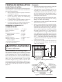
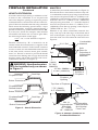
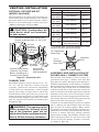
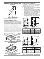
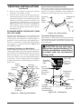
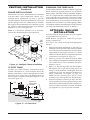
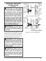
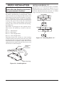
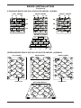
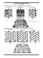
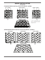
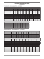
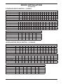
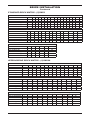
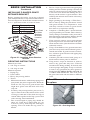
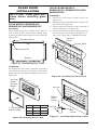
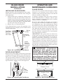
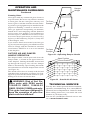
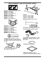
Residential Woodburning Fireplace
OWNER’S OPERATION AND INSTALLATION MANUAL
(V)GM36, (V)GM42 and (V)GM50
Wood Burning Masonry Fireplaces with Insulation
(V)GM36H, (V)GM42H and (V)GM50H
Wood Burning Herringbone Masonry Fireplaces with
Insulation
SAVE THIS BOOK
This book is valuable. In addition to instructing you
on how to install and maintain your appliance, it also
contains information that will enable you to obtain replacement parts or accessory items when needed. Keep
it with your other important papers.
This fireplace is approved for use as a wood burning
fireplace or for use with a vented gas log approved to
ANS Z21.60, Z21.84 or RGA 2-72 standards or for use
with a vent-free gas log heater approved to ANS Z21.11.2
standard.
This wood burning fireplace complies with UL127CAN/ULS-S610-M87 standard as a FACTORY BUILT
APPLIANCE.
FOR CANADA: The authority having jurisdiction (such
as the municipal building department, fire department,
etc.) should be contacted before installation to determine the need to obtain a permit.
Save this manual for future reference.
For more information, visit www.desatech.com
WARNING: Improper installation, adjustment, alteration, service or maintenance can cause injury, property
damage or loss of life. Refer to this manual for assistance or additional information. Consult a qualified
installer or local distributor.
Table of Contents
Safety Information................................................ 2
Specifications....................................................... 3
Fireplace Installation............................................ 6
Venting Installation............................................... 8
Optional Gas Line Installation............................ 12
Safety Information
IMPORTANT: Check local codes
before installing this fireplace.
Before beginning the installation of the fireplace,
read these instructions through completely.
• This DESA fireplace and its components are
safe when installed according to this installation
manual. Unless you use DESA components,
which have been designed and tested for the
fireplace system, you may cause a fire hazard.
• The DESA warranty will be voided by and
DESA disclaims any responsibility for the
following actions.
a. Modification of the fireplace, components,
doors, air inlet system and damper control.
b. Use of any component part not manufactured or approved by DESA in combination
with a DESA fireplace system.
Proper installation is the most important step in
ensuring safe and continuous operation of the
fireplace. Consult the local building codes as to
the particular requirements concerned with the
installation of all factory built fireplaces.
WARNING: Do not install a
fireplace insert in this box unless
the manufacturer's instructions
with the insert specifically state
this fireplace has been tested for
use with this insert.
This fireplace is not intended to be
used as a substitute for a furnace
to heat an entire home. Use for
supplemental heat only.
Brick Installation................................................. 14
Glass Door Installation....................................... 22
Operation and Maintenance Guidelines............. 23
Technical Service............................................... 24
Replacement and Accessory Parts.................... 25
FOR YOUR SAFETY
• Do not store or use gasoline
or any other flammable vapors
or liquids in the vicinity of this
or any other appliance.
• Due to high temperatures, the
appliance should be located
out of traffic and away from
furniture and draperies.
• Do not place clothing or other
flammable materials on or near
the appliance.
• Never leave children unattended when a fire is burning
in the fireplace.
WARNING: Use solid wood
or processed solid fuel firelogs
only. When processed wood
fuel fire logs are used, do not
poke or stir the logs while they
are burning. Use only fire logs
that have been evaluated for
the application in fireplace and
refer to fire log warnings and
caution markings on packaging
prior to use.
WARNING: Always leave
glass doors fully opened or
fully closed when operating
fireplace.
www.desatech.com
112435-01M
Specifications
Models VGM36(H) and GM36(H)
ROUND TOP TERMINATION
SQUARE CHASE-TOP
TERMINATION
1" CHIMNEY AIRSPACE
CLEARANCE TO
COMBUSTIBLE MATERIAL
NO COMBUSTIBLE
MATERIAL ON FACE
COMBUSTIBLE
WALL BOARD
11/2" AIR SPACE
BACK AND SIDES
OUTSIDE AIR
MINIMUM 12" TO
PERPENDICULAR
SIDEWALL
GAS LINE
KNOCKOUTS
HEARTH EXTENSION
60" X 20"
0" TO
BOTTOM
12" EACH SIDE
29"
12"
7.5"
67"
22"
58"
26.625"
49"
30"
0.625"
45"
36"
8"
1"
45"
AIR KIT
KNOCK OUT
LEFT SIDE
21.5"
GAS LINE
KNOCK OUTS
3.5"
10.5"
9.5"
20"
7"
10.75"
15.375"
36"
112435-01M
www.desatech.com
Specifications Continued
Models VGM42(H) and GM42(H)
ROUND TOP TERMINATION
SQUARE CHASE-TOP
TERMINATION
2" CHIMNEY AIRSPACE
CLEARANCE TO
COMBUSTIBLE MATERIAL
NO COMBUSTIBLE
MATERIAL ON FACE
COMBUSTIBLE
WALL BOARD
11/2" AIR SPACE
BACK AND SIDES
OUTSIDE AIR
MINIMUM 18" TO
PERPENDICULAR
SIDEWALL
GAS LINE
KNOCKOUTS
HEARTH EXTENSION
66" X 20"
0" TO
BOTTOM
12" EACH SIDE
12"
30.5"
11"
67"
21.25"
58"
49"
30"
28.5"
0.625"
51"
42"
8"
1"
51"
AIR KIT
KNOCK OUT
LEFT SIDE
24.25"
GAS LINE
KNOCK OUTS
3.5"
23.5"
9.5"
10.5"
8.5"
13"
17"
41.25"
www.desatech.com
112435-01M
Specifications Continued
Models VGM50(H) and GM50(H)
ROUND TOP TERMINATION
SQUARE CHASE-TOP
TERMINATION
2" CHIMNEY AIRSPACE
CLEARANCE TO
COMBUSTIBLE MATERIAL
NO COMBUSTIBLE
MATERIAL ON FACE
COMBUSTIBLE
WALL BOARD
11/2" AIR SPACE
BACK AND SIDES
OUTSIDE AIR
MINIMUM 18" TO
PERPENDICULAR
SIDEWALL
GAS LINE
KNOCKOUTS
0" TO
BOTTOM
12" EACH SIDE
HEARTH EXTENSION
74" X 20"
12"
38.5"
11"
67"
21.25"
58"
49"
30"
28.5"
0.625"
59"
50"
8"
1"
59"
LEFT SIDE
32.75"
AIR KIT
KNOCK OUT
GAS LINE
KNOCK OUTS
3.5"
23.5"
10.5"
9.5"
8.5"
13"
17"
50"
112435-01M
www.desatech.com
Fireplace Installation Framing
selecting location
To determine the safest and most efficient location
for the fireplace, you must take into consideration
the following guidelines:
1. The location must allow for proper clearances
(see Figures 1 and 2).
2. Consider a location where the fireplace will
not be affected by drafts, air conditioning
ducts, windows or doors.
3. A location that avoids the cutting of joists or
roof rafters will make installation easier.
4. An outside air kit is available with this fireplace
(see Optional Outside Air Kit on page 8).
Minimum clearance to
combustibles
Back and sides of fireplace
Front of fireplace
Floor**
Perpendicular wall to opening
Model GM36
Top spacers
Mantel clearance
Chimney outer pipe surface
Models GM36
* Not required at nailing flanges
** See step 2 of Framing
1 1/2" min.*
48" min.
0" min.
18" min.
12" min.
0" min.
see Mantels, page 7
2" min.
1" min.
1. Frame the opening for the fireplace using the
dimensions shown in Figures 1 and 2.
2. If the fireplace is to be installed directly on
carpeting, tile (other than ceramic) or any
combustible material other than wood flooring, the fireplace must be installed upon a
metal or wood panel extending the full width
and depth of the fireplace.
3. Set the fireplace directly in front of this opening and slide the unit back until the nailing
flanges touch the side framing.
4. Check the level of the fireplace and shim with
sheet metal if necessary.
5. Before securing fireplace to prepared framing,
the ember protector (provided) must be placed
between the hearth extension (not supplied)
and under the bottom front edge of the fireplace to protect against glowing embers falling
through. If the fireplace is to be installed on
a raised platform, a Z-type ember protector
(not supplied) must be fabricated to fit your
required platform height. The ember protector
should extend under the fireplace a minimum
of 1 1/2". The ember protector should be made
of galvanized sheet metal (28 gauge minimum
to prevent corrosion.
6. Using screws or nails, secure the fireplace to
the framing through flanges located on the
sides of the fireplace.
WARNING: Do not pack required air spaces with insulation
or other materials.
Minimum/Maximum Chimney Height
The minimum height of the chimney, measured
from the base of the fireplace to the flue gas outlet
of the termination, is 16 feet for straight flue or a
flue with one elbow set. The maximum distance
between elbows is 6 feet. For systems with two
elbow sets, the minimum height is 22 feet. The
maximum height of any system is 50 feet. This
measurement includes the fireplace, chimney sections and the height of the termination assembly
at the level of the flue gas outlet (see Figure 15,
page 11).
67.125"
58.125"
45.25" (36" Models)
51.25" (42" Models)
59" (50" Models)
30.125"
28.250" (36" Models)
Figure 1 - Framing Dimensions
Maintain 1 1/2"
Clearance at Sides
and Back of Fireplace
61" (36" Models)
65" (42" Models)
71" (50" Models)
1 1/2" Clearance
Not Required at
Nailing Flanges
86.5" (36" Models)
92" (42" Models)
100" (50" Models)
Figure 2 - Corner Installation
www.desatech.com
112435-01M
Fireplace Installation Mantels
Continued
Hearth Extension
A hearth extension projecting a minimum of 20"
in front of and a minimum of 12" beyond each
side of the fireplace opening is required to protect
combustible floor construction in front of the fireplace. Fabricate a hearth extension using a material
which meets the following specifications: a layer
of noncombustible, inorganic material having a
thermal conductivity of K=0.84 BTU IN/FT, HR.
F (or less) at 1" thick. For example, if the material
selected has a K factor of 0.25, such as glass fiber,
the following formula would apply:
0.25 x 1.0" = 0.30" thickness required
0.84
Thermal conductivity "K" of materials can be
obtained from the manufacturer or supplier of the
noncombustible material. If the hearth extension
is to be covered, use noncombustible material such
as tile, slate, brick, concrete, metal, glass, marble,
stone, etc. Provide a means to prevent the hearth
extension from shifting and seal gap between the
fireplace frame and hearth extension with a noncombustible material (see Figure 3).
WARNING: Hearth extension
is to be installed only as shown
in Figure 3.
A mantel may be installed if desired (see Figure 4).
Woodwork such as wood trims, mantels or any other combustible material projecting from the front
face must not be placed within 12" (GM36) or 18"
(GM42/50) of the fireplace opening. Combustible
materials above 12" (GM36) or 18" (GM42/50)
and projecting more than 1 1/2" from the fireplace
must not be placed less than 15" (GM36) or 21"
(GM42/50) from the top opening of the fireplace
(NFPA STD 211, Sec. 7-3.3.3).
Mantels or any other combustible material also
may come up to the side edge of the black metal
face of the fireplace just as long as the projection
from the front face fall within the limit shown in
Figure 4.
6"
Ref.
3" Nom.
15" Min.
(GM36)
21" Min.
(GM42/50)
11/2" Max.
12" Min. (GM36)
18" Min. (GM42/50)
Seal Gap
Upper
Section of
Fireplace
Fireplace
Opening
Ember Protector
Top View of Fireplace
Fireplace Front
Raised Hearth
Fireplace Front
Elevated
Safe
Zone for
Projection of
Combustible
Materials
33°
Fireplace Front
Ember Protector
Combustible
Material
12 1/4" Ref.
Hearth
Extension
Seal Gap
7.75" (GM36)
11.5" (GM42/50)
FIREBOX
3" Max.
SAFE ZONE
33°
Min. to
Perpendicular
Side Wall
12" - GM36
18" - GM42/50
Ember Protector
Figure 3 - Hearth Extension
4.5"
Combustible
Material Must
Not Overlap
Front Face
Figure 4 - Mantel Clearances to
Combustible Material
112435-01M
www.desatech.com
Venting Installation
PART NO.
Optional Outside air Kit
(Model ak4/ak4f)
The installation of an outside air kit should be performed during the rough framing of the fireplace
due to the nature of it's location. Outside combustion air is accessed through a vented crawl space
(AK4F) or through a sidewall (AK4).
CAUTION: Combustion air
inlet ducts shall not terminate
in attic space.
Secure to Collars with Metal Tape,
Screws or Straps (Min. of 1/4" x 20"
in size)
Air Inlet
Location
Must Allow
For Bushes
or Snow
Air Inlet
Eyebrow
Vent Hood
Vented Crawl Space
Required for
(Check Local Codes
Wall Installation
Before Installing in a
Vented Crawl Space)
Figure 5 - Outside Air Kit
Chimney Pipe
The DESA chimney system consists of 12", 18",
24", 36"' and 48" snap-lock, double-wall pipe
segments, planned for maximum adaptability
to individual site requirements. Actual lengths
gained after fitting overlaps must be taken into
consideration (lineal gain) and are given in the
lineal gain chart (see Figure 6). Lineal Gain is the
actual measurable length of a part after two or more
parts are connected. For Canada, use chimney parts
designated "HT".
WARNING: The opening in the
collar around the chimney at the
top of the fireplace must not be
obstructed. Never use blown insulation to fill the chimney enclosure.
LINEAL GAIN
DESCRIPTION
GAIN (IN)
Georgian
Fireplace
66 1/2"
12-12DM
Pipe Section
10 5/8"
12-12HT
18-12DM
Pipe Section
16 5/8"
18-12HT
24-12DM
Pipe Section
23 5/8"
24-12HT
36-12DM
Pipe Section
34 5/8"
36-12HT
48-12DM
Pipe Section
46 5/8"
48-12HT
RLT-12D
Round Termination
7 3/4"*
RLT-12HT
Square Chase-Top
STL-12D
7" to 15"*
with Slip Section
* The lineal gain for the terminations is measured to the flue gas outlet height.
15" Galvanized
Outer Pipe
Hemmed
End
12 3/8"
Stainless
Inner Pipe
Figure 6 - Lineal Gain
Assembly and installation of
double wall chimney system
Each double wall chimney section consists of a
galvanized outer pipe, a stainless steel inner flue
pipe and a wire spacer. The pipe sections must be assembled independently as the chimney is installed.
When connecting chimney directly to the fireplace,
the inner flue pipe section must be installed first
with the lanced side up. The outer pipe section can
then be installed over the flue pipe section with the
hemmed end up. Press down on each pipe section
until the lances securely engage the hem on the fireplace starter. The wire will assure the proper spacing
between the inner and outer pipe sections.
Continue to assemble chimney sections as outlined
above, making sure that both the inner and outer
pipe sections are locked together. When installing double wall snap-lock chimney together, it is
important to assure the joint between the chimney
sections is locked. Check by pulling chimney
upward after locking. The chimney will not come
apart if properly locked. It is not necessary to add
screws to keep the chimney together (exception,
see Figure 9, page 10).
www.desatech.com
112435-01M
Venting Installation
Continued
Using ELBOW offsets (30E-12DM)
1. To achieve desired offset, you may install
combinations of 12", 18", 24", 36" and 48"
length of double wall pipe (see offset chart
and Figure 7).
OFFSET
A
RISE
B
12"
CHIMNEY LENGTH
18" 24" 36" 48"
2. Chimney weight above offset rests on return
elbow. Straps must be securely nailed to rafters
or joists (see Figure 8, details a and b).
3. Maximum length of pipe between supports
(return elbow or 12S-12DM) is 6' of angle
run. Maximum of two 6' angle run sections
per chimney system (see Figure 7).
4. All pipe connections between the offset and
return must be secured with two screws on
the outer pipe only (see Figure 9, page 10).
Do not penetrate the inner stainless.
4 3/8" 16 3/8"
ELBOW SET ONLY
9 3/4" 25 1/2"
1
See Detail A
12 3/4" 30 3/4"
1
3
15"
34 /4"
1
2" Min.
18"
40"
1
1
21 1/4" 46 1/4"
1
23 3/4" 49 1/4"
1
1
27 3/4" 56 3/4"
1
Straps
30"
60 3/4"
1
1
Straps
33"
66"
1
Detail B
See Detail B
Angle Firestop
36"
71"
1
1
1
38 /4"
75"
2
41 1/4" 80 1/4"
1
1
1
45"
86 3/4"
2
46 3/4" 89 1/2"
1
1
1
Straps
51"
97"
1
1
Straps
1
53 /4" 101"
2
1
1
Detail A
56 /4" 106 /4"
2
Return Elbow
59 1/4" 111 1/2"
1
1
1
Figure 8 - Ceiling Support Pipe
61 3/4" 115 1/2" 1
2
12S-12DM
64 3/4" 120 3/4"
1
2
68 1/4" 127"
2
1
70"
130"
1
1
2
74 1/4" 137 1/2" 1
2
1
76 3/4" 141 1/2"
1
2
1
79 3/4" 146 3/4"
4
OFFSET CHART (22-50 FT. SYSTEM HEIGHT)
Return
Elbow
Return
Elbow
Offset
Elbow
Return
Elbow
Offset
Elbow
6' Max.
Return
Elbow
6' Max. Ceiling
Support Pipe
12S-12DM
Return
Elbow
6' Max.
Offset
Elbow
A
Offset
Elbow
Offset
6' Max. Elbow
B
6' Max.
6' Max.
C
Figure 7 - Typical Offset Terminations
112435-01M
www.desatech.com
Venting Installation
Continued
Screws
B
A
Figure 9 - Elbow Offset
Penetrating the roof
To maintain a 1" (GM36) or 2" (GM42/GM50)
clearance to the pipe on a roof with a pitch, a
rectangular opening must be cut.
1. Determine the center point through which the
pipe will penetrate the roof.
2. Determine the center point of the roof. Pitch
is the distance the roof drops over a given
span, usually 12". A 6/12 pitch means that
the roof drops 6" for each 12" one measure
horizontally down from the roof rafters.
3. Use the roof opening chart (Figure 12) to
determine the correct opening length and
flashing required.
17" Min.
Firestop Spacers (FS-10,
1100EFS-10DM for GM36)
1" Min.
Firestop spacers are required at each point where
the chimney penetrates a floor space. Their purpose
is to establish and maintain the required clearance
between the chimney and the combustible materials.
When the pipe passes through a framed opening into
a living space above, the firestop must be placed onto
the ceiling from below as shown in Figure 10.
They also provide complete separation from one floor
space to another or attic space as required by most
codes. When the double wall pipe passes through a
framed opening into an attic space, the firestop must
be placed into an attic floor as shown in Figure 11.
Existing
Ceiling
Frame
Firestop
Spacer
1" Min.
Opening "A"
Pitch
Slope
Flat
0-6/12
6/1212/12
0°
26.6°
45.0°
24"
Figure 11 - Firestop Spacer with Attic
Space Above Ceiling
V12F-10DM
19.5" Min.
30" Min.
2" Min.
2" Min.
2" Min.
Screws or Staples
(Min. of 8)
Existing
Ceiling
Frame
10
Opening Used Flashing
"A" Max.
Model No.
17"
V6F-10DM
19"
V6F-10DM
Roof Opening GM36
Screws or
Staples
(Min. of 8)
Figure 10 - Firestop Spacer with Living
Space Above Ceiling
Firestop
Spacer
30" Min.
1" Min.
Opening "A"
Pitch
Slope
0°
26.6°
Opening
"A" Max.
19.5"
22'
Used Flashing
Model No.
V6F-10DM
V6F-10DM
Flat
0-6/12
6/1212/12
45.0°
27"
V12F-10DM
Roof Opening GM42/50
Figure 12 - Roof Opening Measurements
www.desatech.com
112435-01M
Venting Installation
Continued
4. Remove the shingles around the opening
measured. Cut out this section.
5. Add the next sections of the pipe until the
end penetrates the roof line. Check to see that
the proper clearances are maintained. Extend
chimney by adding sections of double wall
pipe until pipe is minimum of 30" above the
highest point of the roof cutout. Termination
and chimney must extend a minimum of
36" above the highest point where it passes
through the roof.
Storm Collar Installation (SC2-1)
Place storm collar over pipe and slide down until
it is snug against the open edge of the flashing (see
Figure 14). Apply waterproof caulk around the
perimeter of the collar to provide a proper seal.
Chimney
Pipe
Waterproof
Caulk
Storm
Collar
Flashing
Flashing installation (v6f-10dm
or v12f-10dm)
Determine the flashing to be used with the roof
opening chart. Slide flashing over pipe until base
is flat against roof. Replace as many shingles as
needed to cover exposed area and flashing base.
Secure in position by nailing through shingles
(see Figure 13). DO NOT NAIL THROUGH
FLASHING CONE.
Installing Flashing on a Metal Roof
When installing the flashing on a metal roof, it is
required that putty tape be used between the flashing and the roof. The flashing must be secured to
the roof using #8 x 3/4" screws and then sealed
with roof coating to prevent leakage through the
screw holes. A roof coating must also be applied
around the perimeter of the flashing to provide a
proper seal.
Storm
Overlap
Collar
Shingles Top
Flashing
and Sides Only
Cone
Nail Only
Outer
Perimeter
of Flashing
Figure 14 - Storm Collar
Terminations/Spark Arrestor
The fireplace system must be terminated with the
listed round top or chase terminations. In any case,
refer to the installation instructions supplied with
the termination.
CAUTION: Do not seal openings on the rooftop flashing. Follow the installation instructions
provided with the termination
being used.
Stainless
Inner Flue
Pipe
Secure
Termination
to Outer
Pipe with 3
Screws
RTL-10D
Level of
Flue Gas
Outlet
Waterproof
Caulking
Storm
Collar
Flashing
Overlap
Shingles (Top
and Sides of
Flashing Base)
Underlap
Shingles
at Bottom
Figure 13 - Flashing Installation
112435-01M
www.desatech.com
Underlap
Shingles
Figure 15 - Termination
11
Venting Installation
Continued
Chase installations
Instructions for chase installations are included
with the chase style termination chosen. In a
multiple chase installation, be sure to provide
adequate distance between terminations to prevent
smoke spillage from one termination to another.
We suggest that terminations be separated at least
24" center to center and stacked at a vertical height
difference of 18" (see Figure 16).
Note: If a decorative shroud is to be installed,
contact the manufacturer for specifications.
18"
Min.
Typ.
24" Min.
24" Min.
Figure 16 - Multiple Chase Installation
10 foot rule
All flue gas outlet chimney terminations must
extend a minimum of 3 feet in height above the
highest point where it passes through the roof and
must be at least 2 feet above the highest point of
the roof that is within a horizontal distance of 10
feet (see Figure 17).
Level of
Flue Gas
Outlet
10'
10'
2' Min.
finishing the fireplace
Combustible materials, such as wallboard, gypsum
board, sheet rock, drywall, plywood, etc. may make
direct contact with sides and top around the fireplace
face. It is important that combustible materials do
not overlap the face itself. Brick, glass, tile or other
noncombustible materials may overlap the front
face provided they do not obstruct essential openings like louvered slots or any other opening. When
overlapping with a noncombustible facing material,
use only noncombustible mortar or adhesive.
Optional Gas Line
Installation
Gas line hook up should be done by your supplier
or a qualified service person.
Note: Before you proceed, make sure your gas
supply is turned off.
Use only a 1/2" black iron pipe and appropriate
fittings.
1. Remove knockout indentation on refractory or
firebrick wall located above the refractory hearth
floor. The knockout indentation must be firmly
tapped with any solid object such as a 1/2" dowel
until it is released. Remove fragmented portions
of refractory (see Figure 18, page 13).
2. Remove gas line cover plate located on either
side of fireplace and pull out insulation from gas
line conduit sleeve. Save insulation for reuse.
Replace screws.
3. Run a 1/2" black iron gas line into the fireplace
through the rear at gas line conduit sleeve (if
using a raised platform, add height). Provide
sufficient gas line into fireplace chamber for
fitting connection (see Figure 19, page 13).
Note: Secure incoming gas line to wood
framing to provide rigidity for threaded end.
4. Repack insulation around gas line and into
sleeve opening. Seal any gaps between gas line
and refractory knockout hole with refractory cement or commercial furnace cement, Install the
gas appliance or cap-off gas line if desired.
3' Min.
2' Min.
3' Min.
Figure 17 - 10 Foot Rule
12
www.desatech.com
112435-01M
Optional Gas Line
Installation
Continued
CAUTION: All gas piping
and connections must be tested
for leaks after the installation
is completed. After ensuring
that the gas valve is on, apply
soap and water solution to all
connections and joints. Bubbles
forming show a leak. Correct
all leaks at once. DO NOT USE
AN OPEN FLAME FOR LEAK
TESTING AND DO NOT OPERATE ANY APPLIANCE IF A LEAK
IS DETECTED. LEAK TESTING
SHOULD BE DONE BY A QUALIFIED SERVICE PERSON.
WARNING: Do not operate an unvented gas log set in
this fireplace with the chimney
removed.
If you install a decorative gas appliance (vented
gas log), the decorative gas appliance must comply
with the Standard for Decorative Gas Appliance
for Installation in Solid Fuel Burning Fireplaces,
ANS Z21.60, Z21.84 or RG 2-72 and shall also be
installed in accordance with the National Fuel Gas
Code, ANSI 7223NFPA 54 latest edition.
Outside of
Fireplace
Gas Line
Conduit
Remove
Knockout
Insulation
Side
Firebrick
Finished
Side
1/2" Dowel
Gas
Conduit
Cover
Refractory
Knockout
Plug
Figure 18 - Gas Line Knockout
Outside of
Fireplace
Gas
Line
Conduit
Incoming
1/2" Black
Iron Pipe
Side
Firebrick
Finished
Side
Seal
Opening
Repack
with
Insulation
Refractory
Cement
Provide Enough Threaded
End for Fitting Connection
Figure 19 - Gas Line Installation
WARNING: If the fireplace
has been used for wood burning,
the firebox and chimney must be
cleaned of soot, creosote and
ashes be a qualified chimney
cleaner. Creosote will ignite if
heavily heated.
WARNING: When using a
decorative vented gas log, the
damper must be removed or
permanently locked in the fully
open position and the glass
doors must be in the fully open
position.
112435-01M
www.desatech.com
13
Brick Installation
Installing Brick "S"
Use brick “S” if an optional gas line is installed.
Mount brick “S” as shown in Figure 21. It is
important that the knockout hole is in its proper
location. The knockout hole on brick “S” should
align with the hole on the brick housing.
Installation of brick should be
done after the fireplace is placed
in a permanent location.
The brick housing panels are already installed in
the firebox. Each housing is stamped with a letter
(full size bricks are not stamped). These letters will
help identify the brick when installing. It is important to install these bricks exactly as instructed.
Press the brick firmly into the brick housing until
it snaps. The groove line on the side of the brick
will come in contact with the flange on the brick
housing. This secures the brick into the housing.
See Figure 20.
LEFT PANEL
The bricks are packaged in four separate boxes.
D
FULL of the FULL
These boxes are labeled by sections
firebox.
C
Box #1 - Hearth Panel
Box #2 - Rear Panel
Box #3 - Left or Right Panel
S
Box #4 - Left or Right Panel
Install the bricks one section at a time starting
with the hearth panel followed by the rear panel
and then the left or right panel. It is important to
install the bricks in sequence. Note: The left and
right panels have identical bricks. Please note, full
size bricks are NOT stamped.
LEFT PANEL
D
FULL
RIGHT PANEL
B
FULL
C
FULL
B
A
A
S
S
RIGHT PANEL
B
FULL
B
A
A
FULL
D
C
S
Figure 21 - Installing Brick “S”
Stamped
Letter
Location
Brick
Flanges
Brick Housing
Figure 20 - Installing Brick
14
www.desatech.com
112435-01M
F
Brick Installation
Continued
Standard Brick Installation for Model (V)GM36
LEFT PANEL
Q
P
AF
AG FULL
AF
AF
C
C
FULL
AE
FULL
AE
AE
AF
AG
FULL
AF
FULL
D FULL FULL D
AN
AF
FULL
AC
C
P
FULL AG
AC
C
FULL
C
AE
FULL
FULL
Q
AH
AI
D FULL FULL D
AC
AD
Q
D FULL FULL D
AE
FULL
AG
C
AC
AG FULL
Q
AI
AE
FULL
RIGHT PANEL
REAR PANEL
AH
AT
AD
AG
HEARTH PANEL
G
H
G
FULL
H
FULL FULL
I FULL FULL
M
FULL I
FULL FULL
AB
L
M
L
L
AB
HERRINGBONE Brick Installation for Model (V)GM36H
LEFT PANEL
HL
REAR PANEL
HL
HJ
HJ
HF
HAAA
HF
HJ
HSS
FULL
HYY
HSS
FULL
HF
HF
HAAH
FULL
HYY
HUU
HC
HZZ
HL
HSS
FULL
HAAB OR HD
HVV
HF
HAAF
FULL
HAAH
HD
HAAF
FULL
HL
HC
HD
HAAF
HVV
HL
HJ
FULL
HVV
HF
FULL
HAAH
FULL
FULL
HAAG
HJ
HL
HJ
FULL
HJ
HL
HXX
HAAH
FULL
FULL
HJ
HJ
FULL
FULL HYY
HJ
RIGHT PANEL
HL
HTT HL
HL
HAAC
HWW
HL
HE
HAAG
BOTTOM HEARTH
HAAB OR HD
HL
HAAD
HRR
FULL
FULL
HF
HQQ
HJ
AB
L
HOO
HF
HJ
HAAE
HL
HL
112435-01M
HPP
FULL
FULL
HF
HAAD
L
www.desatech.com
L
AB
15
Brick Installation
Continued
Standard Brick Installation for Model (V)GM42
LEFT PANEL
Q
O
D
FULL
FULL
C
D
D
FULL
FULL
R
Full
F
FULL
U
FULL
Y
V
FULL
FULL
FULL
W
X
AA
FULL
FULL
D
FULL
C
OR
**S
U
Y
**See instruction on page 14
before installing brick "S"
V
FULL
FULL
K
L
C
Full
FULL
FULL
K
L
D
FULL
FULL
HEARTH PANEL
OR
**S
C
A
E
D
FULL
FULL
B
O
FULL
A
F
FULL
FULL
B
E
FULL
Q
A
E
FULL
E
B
F
FULL
FULL
F
B
FULL
FULL
E
A
Z
FULL
E
F
B
FULL
C
RIGHT PANEL
Q
FULL
A
FULL
REAR PANEL
Z
F
B
A
FULL
FULL
C
R
W
X
AA
K
L
K
L
Herringbone Brick Installation for Model (V)GM42H
LEFT PANEL
REAR PANEL
HL
HL
HAAF
HFF
HF
HAAF
HAA
HJ
FULL
FULL
HJ
HLL
FULL
HJ
HC
HC
HLL
FULL
HI
HL
HI
HC
HI
HKK
HNN
OR
HD
HEARTH PANEL
HN
FULL
HC
HJ
HD
HDD
OR
HD
HI
FULL
HC
HCC
HI
FULL
FULL
HB
HBB
HAAF
FULL HJ
FULL
FULL
HLL
HA
FULL
HE
FULL
FULL
FULL
FULL
HB
FULL
HJ
FULL
FULL
HA
FULL
HAAF
FULL
FULL
FULL
HF
HJ
HF
HA
HB
HAAF
HMM
HJ
HF
FULL
HF
HL
HL
HJ
HK
HF
RIGHT PANEL
HL
HI
HG
HGG
FULL
FULL
HM
FULL
HHH
FULL
FULL
HZ
FULL
FULL
HF
L
FULL
HF
HJ
HJ
HO
HL
L
HL
L
AA
16
HII
HJJ
HJ
L
HL
AA
www.desatech.com
112435-01M
Brick Installation
Continued
Standard Brick Installation for Model (V)GM50
REAR PANEL
LEFT PANEL
O
D
FULL
C
D
P
R
FULL
E
B
B
FULL
FULL
AN
F
FULL
Full
B
E
FULL
FULL
FULL
G
H
FULL
FULL
FULL
I
Full
M
FULL
FULL
OR
**S
H
FULL
FULL
FULL
**See instruction on
page 14 before installing brick "S"
G
FULL
FULL
D
C
HEARTH PANEL
OR
**S
D
C
FULL
AT
F
D
C
FULL
A
FULL
FULL
FULL
B
F
O
FULL
A
F
FULL
FULL
Q
B
E
FULL
FULL
R
E
FULL
FULL
FULL
E
P
FULL
FULL
FULL
F
A
C
FULL
RIGHT PANEL
Q
FULL
F
FULL
Q
E
A
FULL
FULL
Q
B
FULL
FULL
C
D
Q
FULL
I
M
FULL
J
K
K
K
K
J
N
L
L
L
L
N
Herringbone Brick Installation for Model (V)GM50H
LEFT PANEL
HAAF
HAAF
HFF
HL
FULL HK
HF
HAAF
HE
HA
FULL HB
FULL
FULL
HAAF
HCC
HBB
HU
HY
HM
FULL
FULL
FULL
HZ
FULL
HO
N
L
HF
HL
HJ
L
FULL
FULL
FULL
HD
HD
HV
HV
HF
FULL
FULL HQ
FULL
FULL
HJ
HG
HV
HX
OR
HC
HR
HI
HG
FULL
HH
HD
HI
FULL
FULL
FULL
HEARTH PANEL
HN
112435-01M
HU
FULL
HD
HDD
OR
HD
FULL
HC
HC
HV
FULL
FULL
FULL
HEE
HF
FULL
HU
HC
FULL
HC
HB
HJ
HF
FULL
FULL
HA
HC
HL
HW
HC
FULL
FULL
HL
HT
HF
FULL
FULL
FULL
HF
HJ
HF
FULL
FULL HB
HF
HJ
HA
FULL
HAAF
HL
HL
HAA
HJ
HF
RIGHT PANEL
REAR PANEL
HL
FULL
HF
HL
HJ
L
www.desatech.com
HF
HL
L
HP
HS
N
17
Brick Installation
Continued
Standard Brick Matrix - (V)GM36
Brick Matrix
Box #1 Hearth-36
Box #2 Rear-36
Box #3 Left or Right-36
Box #4 Left or Right-36
TOTAL
Standard brick matrix for model (V)GM36
Full
A B C D E F G H I
J K
8
- 2 2 2 9
- 6 6 5
5
27
0 0 6 6 0 0 2 2 2 0 0
L
3
3
M
2
2
Standard brick matrix for model (V)GM36 (Continued)
Brick Matrix
Q
R
S
T
U
V W X
Y
Z
AA
Box #1 Hearth-36
Box #2 Rear-36
2
Box #3 Left or Right-36
1
Box #4 Left or Right-36
1
TOTAL
4
0
0
0
0
0
0
0
0
0
0
AB
2
2
N
0
AC
3
3
6
O
0
P
1
1
2
AD
1
1
2
Standard brick matrix for model (V)GM36 (Continued)
Brick Matrix
AE
AF
AG
AH
AI
TOTAL
Box #1 Hearth-36
21
Box #2 Rear-36
2
25
Box #3 Left or Right-36
3
3
3
1
21
Box #4 Left or Right-36
3
3
3
1
21
TOTAL
6
6
6
2
2
88
HERRINGBONE Brick Matrix - (V)GM36H
Brick Matrix
Box #1 Hearth-36
Box #2 Rear-36
Box #3 Left-36
Box #4 Right-36
TOTAL
HERRINGBONE brick matrix for model (V)GM36H
Full
HC
HD
HE
HF
HJ
HL
HOO HPP
4
3
2
3
1
1
6
1
2
1
4
7
6
1
1
1
5
3
3
1
1
4
1
1
19
2
4
1
9
12
14
1
1
HQQ
1
1
HRR
1
1
HERRINGBONE brick matrix for model (V)GM36H (Continued)
Brick Matrix
HSS
HTT
HUU
HVV HWW HXX
HYY
HZZ HAAA
Box #1 Hearth-36
Box #2 Rear-36
3
1
1
Box #3 Left-36
3
1
1
Box #4 Right-36
3
1
1
TOTAL
3
1
1
3
1
1
3
1
1
HERRINGBONE brick matrix for model (V)GM36H (Continued)
Brick Matrix
HAAC HAAD HAAE HAAF HAAG HAAH
AB
L
Box #1 Hearth-36
2
1
2
3
Box #2 Rear-36
1
Box #3 Left-36
Box #4 Right-36
3
2
4
TOTAL
1
2
1
3
2
4
2
3
18
www.desatech.com
HAAB
1
1
2
TOTAL
24
27
23
26
100
112435-01M
Brick Installation
Continued
Standard Brick Matrix - (V)GM42
Brick Matrix
Box #1 Hearth-42
Box #2 Rear-42
Box #3 Left or Right-42
Box #4 Left or Right-42
TOTAL
Standard brick matrix for model (V)GM42
Full
A B C D E F G H I
J K
10
- 4
9
- 6 6 9
3 3 3 3 9
3 3 3 3 37
6 6 6 6 6 6 0 0 0 0 4
L
4
4
Standard brick matrix for model (V)GM42 (Continued)
Brick Matrix
Q R S T U V W X Y Z AA AB AC
Box #1 Hearth-42
- 2 2
2
2 2 2
Box #2 Rear-42
1 - 2
Box #3 Left or Right-42 1 1 1 Box #4 Left or Right-42 1 1 1 TOTAL
3 2 2 0 2 2
2
2 2 2
2
0
0
M
0
AD
0
N
0
AE
0
O
1
1
2
P
0
AF
0
Standard brick matrix for model (V)GM42 (Continued)
Brick Matrix
AE
AF
AG
AH
AI
TOTAL
Box #1 Hearth-42
30
Box #2 Rear-42
24
Box #3 Left or Right-42
25
Box #4 Left or Right-42
TOTAL
0
0
0
0
0
25
104
HERRINGBONE Brick Matrix - (V)GM42H
Brick Matrix
Box #1 Hearth-42
Box #2 Rear-42
Box #3 Left-42
Box #4 Right-42
TOTAL
HERRINGBONE brick matrix for model (V)GM42H
Full
HA HB HC HD HE HF HG HI HJ HK
8
2
1
2
3
9
3
2
1
1
6
6
3
1
1
1
4
1
1
9
2
1
1
4
2
32
3
3
5
3
1
8
1
6
12
1
HL
3
3
2
1
9
HERRINGBONE brick matrix for model (V)GM42H (Continued)
Brick Matrix
HO HZ HAA HBB HCC HDD HEE HFF HGG HHH HII
Box #1 Hearth-42
1
1
1
1
1
Box #2 Rear-42
1
1
Box #3 Left-42
1
1
1
Box #4 Right-42
TOTAL
1
1
1
1
1
1
0
1
1
1
1
HM
1
1
HJJ
1
1
HN
1
1
HKK
1
1
HERRINGBONE brick matrix for model (V)GM42H (Continued)
Brick Matrix
HLL HMM HNN HAAF
L
AA
TOTAL
Box #1 Hearth-42
4
2
33
Box #2 Rear-42
27
Box #3 Left-42
5
28
Box #4 Right-42
TOTAL
112435-01M
3
3
1
1
1
1
5
4
2
www.desatech.com
26
114
19
Brick Installation
Continued
Standard Brick Matrix - (V)GM50
Brick Matrix
Box #1 Hearth-50
Box #2 Rear-50
Box #3 Left or Right-50
Box #4 Left or Right-50
TOTAL
Standard brick matrix for model (V)GM50
Full
A B C D E F G H I
J K
12
- 2 2 2 2 4
15
- 6 6 9
3 3 3 3 9
3 3 3 3 45
6 6 6 6 6 6 2 2 2 2 4
L
4
4
Standard brick matrix for model (V)GM50 (Continued)
Brick Matrix
Q
R
S
T
U
V W X
Y
Z
AA
Box #1 Hearth-50
Box #2 Rear-50
3
Box #3 Left or Right-50
1
1
Box #4 Left or Right-50
1
1
TOTAL
5
2
0
0
0
0
0
0
0
0
0
M
2
2
N
2
2
AB
0
AC
0
HK
1
1
HL
3
2
2
2
9
O
1
1
2
P
2
2
AD
0
standard brick matrix for model (V)GM50 (Continued)
Brick Matrix
AE AF AG AH
AI
TOTAL
Box #1 Hearth-50
32
Box #2 Rear-50
32
Box #3 Left or Right-50
25
Box #4 Left or Right-50
TOTAL
0
0
0
0
0
25
114
HERRINGBONE Brick Matrix - (V)GM50H
Brick Matrix
Box #1 Hearth-50
Box #2 Rear-50
Box #3 Left-50
Box #4 Right-50
TOTAL
HERRINGBONE brick matrix for model (V)GM5H0
Full HA HB HC HD HE HF HG HH HI HJ
10
4
2
2
3
12
3
5
2
2
1
2
6
3
1
1
1
4
1
9
1
2
2
1
37
3
3
7
5
1
12
2
1
2
7
HERRINGBONE brick matrix for model (V)GM50H (Continued)
Brick Matrix
HN
HO
HP
HQ
HR
HS
HT
HU
HV
HW
Box #1 Hearth-50
1
1
1
1
1
1
Box #2 Rear-50
1
Box #3 Left-50
Box #4 Right-50
3
4
1
TOTAL
1
1
1
1
1
1
1
3
4
1
HERRINGBONE brick matrix for model (V)GM50H (Continued)
Brick Matrix
HZ HAA HBB HCC HDD HEE HFF HAAF
L
N
Box #1 Hearth-50
1
4
2
Box #2 Rear-50
1
1
Box #3 Left-50
1
1
1
5
Box #4 Right-50
TOTAL
20
1
1
1
1
1
1
1
www.desatech.com
1
5
4
1
HX
1
1
HM
1
1
HY
1
1
TOTAL
38
32
28
28
126
112435-01M
Brick Installation
Continued
Installing Z-shaped Grate
Retainer Bracket
Before grouting the bricks, locate the z-shaped
grate retainer brackets on top of the hearth bricks as
shown in Figure 22. Position the retainer brackets
at 8 3/4" apart from center to center of notch.
Model
GM36
GM42
GM50
Distance Apart
3 1/4" Centers
4 1/4" Centers
8 3/4" Centers
See Chart
for Grate
Retainer
Brackets
Location
Figure 22 - Installing Grate Retainer
Bracket
Grouting instructions
Material provided:
2 - 9 lb. bags of cement
2 - 9 lb. bags of sand
Material required:
1 - Piping bag
1 - Joints striker
1 - Heavy duty mixing bucket
1 - Trowel
1. Moisten brick surface with a damp sponge or a
spray bottle just prior to application. When the
bricks are wet, any excess grout mixture that
might have gotten onto the brick will easily
wipe off.
2. In a heavy duty mixing bucket, pour seven (7)
cups of water in first, then add in 4.5 lbs. (half
of a bag) of sand and 4.5 lbs (half of a bag) of
cement. Mix together well using a power drill
with a mixing wand attachment.
3. The overall length of piping bag should be
about 16". If the bag is longer than 16", cut
it down to size by removing end with larger
opening. This will make the bag easier to
handle.
112435-01M
4. Put 2 to 3 cups of grout mixture into piping bag
making sure the smaller opening is downward
and over a moist towel to avoid spilling. Place
a wet towel over the bucket making sure it is
directly on the surface of grout mixture. This
will keep the mixture moist and it will not dry
out before use.
5. Begin grouting by first doing a “Filler Pass”.
This is done by filling the joint about 3/4 full
with grout mixture. It is important to work
with only 6 bricks at a time so grout doesn't
have time to set up before striking.
6. Complete a “Finishing Pass” around 6 bricks
you just put filler pass around. This is done by
slowly filling in remainder of the joint with a
thick amount of grout mixture. Mixture should
be a little higher than the brick surface.
7. Using a trowel, remove excess grout mixture
by moving trowel in the direction of the joint.
Grout mixture in the joint should now be flush
with brick surface.
8. Using a Joint Striker, force grout mixture into
joint and sweep back and forth until grout is
smooth and round. If grout becomes too shallow, add more grout mixture with piping bag
and strike again.
9. Continue procedure around each group of 6
bricks until an entire panel is finished.
10. Using trowel, scrape in direction of joints to
remove any grout that may have collected
around bricks during striking. If desired, take
a moist sponge and lightly sweep over bricks
to remove any grout that may have gotten on
bricks. DO NO PRESS HARD OR RUB IN
A CIRCULAR MOTION. This will press
the grout into brick and turn brick a different
color.
Allow 72 hours before operating
fireplace.
Figure 23 - Grouting Brick
www.desatech.com
21
Glass Door
Installation
IMPORTANT: Install glass door
frame before installing glass
door.
DOOR MODELS BDM36E/G/C,
BDM42E/G/C AND BDM50E/G/C
Assembly
Insert L-shaped gussets starting at left top portion of door frame. Gusset holes should align
with screw holes on the frame. Secure using flat
head screws.
Flat Head Screw
door frame MODELS
BDMO36E/G/C, BDMO42E/G/C AND
BDMO50E/G/C
Installation
1. Remove screws from smoke shelf (see
Figure 26).
2. Mount top door frame and secure with screws
provided (see Figure 26).
3. Place bottom door frame on top of ash lip at
front of fireplace (see Figure 27).
4. Secure bottom door frame to brick with two
hex screws provided as shown in Figure 27 using a 7/16" open end or adjustable wrench.
Top Door
Frame
Smoke Shelf
Top
L-Shaped Gusset
Bottom
Figure 24 - Assembling Door Frame
Installation
To install glass door frame, construct an opening
(see table) on front face of fireplace. Insert door
frame into face opening and tighten screws (see
Figure 25).
3/4" Cap
Screw
Top and
Bottom
Figure 26 - Installing Top Door Frame
A
Ash Lip
B
Bottom
Door
Frame
MODEL
1" Cap Screw
Left and Right
A
B
GM36
37"±1/4" 34"±1/4"
GM42
43"±1/4" 34"±1/4"
GM50
51"±1/4" 34"±1/4"
Figure 25 - Installing Door Frame
22
Ash Lip
Hex
Screw
Figure 27 - Installing Bottom Door Frame
www.desatech.com
112435-01M
Glass Door
Installation
Operation and
Maintenance Guidelines
Continued
Glass Doors
Installing glass doors
Spring clips have been installed but some adjustments may be needed. Install the doors using the
following steps:
1. With bi-fold doors completely folded, insert
bottom pivot pin into pivot hole located near
bottom corner of front face opening and swing
door to vertical position making sure top pins
slide into door track. Door is installed when
top door pin snaps into spring clip.
2. Repeat step 1 for remaining door.
If you find the doors do not close properly or do
not appear level or straight, proceed with section
on door adjustment,
Fold Door
and Slide
Top Pins
Into Track
Spring
Clip
Insert Pin
into Spring
Clip
Insert
Bottom
Pivot Pin
into Hole
Pivot
Hole
Figure 28 - Installing Bi-Fold Doors
Door Adjustment
Remove doors and slightly loosen lower pivot clips
and upper spring clips. Replace doors and fully close
them. Use 1/8" shims (any material) to level doors.
Once proper setting is achieved, carefully open doors
enough so that you can access spring clips with a phillips screwdriver. Tighten screws. See Figure 29.
Glass doors are optional with the fireplace. When
fireplace is in operation, doors must be fully
opened or fully closed position only or a fire hazard
may be created (see Figure 30).
A fireplace equipped with glass doors operates
much differently than a fireplace with an open
front. A fireplace with glass doors has a limited
amount of air for combustion.
Excessive heat within the fireplace can result if
too large a fire is built or if combustion air gate is
not completely open. The following tips should
be followed to assure that both the fireplace and
glass door retain their beauty and function properly. Both the flue damper and glass doors must
be fully opened before starting fire. This will
provide sufficient combustion air and maintain
safe temperatures in firebox.
IMPORTANT: The glass must be allowed to
warm slowly and evenly. The tempered glass will
withstand a gradual temperature rise to 550° F,
which is more than a normal fire will generate.
Such materials as pitch/wax laden logs, very dry
mill end lumber and large amounts of paper or
cardboard boxes can create an excessively hot fire
and should not be burned in this fireplace. Always
keep the fire well back from the doors and never
allow flames to contact the glass.
WARNING: Fireplaces
equipped with glass doors
should be operated only with
doors fully opened or doors fully
closed. Doors, if left partly open,
may draw gas and flame out of
the fireplace opening creating
risks of both fire and smoke.
Doors Fully Closed
Fireplace Front
Fireplace Front
Doors
Fully Opened
Figure 29 - Adjusting Bi-Fold Doors
112435-01M
Figure 30 - Bi-Fold Glass Doors
www.desatech.com
23
Operation and
maintenance Guidelines
Damper
Weight
Continued
Cleaning Glass
Clean glass with any commercial glass cleaner or
soap and water. Do not use any abrasive material
to clean glass. Do not clean glass with any cool
water if glass is still hot from the fire and smoke.
A gas line or gas log lighter may be installed for the
purpose of installing a vented or vent-free decorative gas appliance incorporating an automatic
shutoff device and complying with the Standard
for Decorative Gas Appliances for Installation in
Vented Fireplaces, ANSI Z21.60 or American Gas
Association draft requirements for Gas Fired Log
Lighters for Wood Burning Fireplaces, Draft NO.
4 dated August, 1993.
If you wish to install an unvented (vent-free) gas
log set, only unvented gas log sets which have been
found to comply with the standard for unvented
room heaters, ANSI Z21.11.2 are to be installed
in this fireplace.
outside air and damper
handle operation
To Close
Damper
Damper
Weight
To Open
Damper
Figure 31 - Operating Damper Handle
The damper handle, which opens and closes the
damper blade, is located in the upper front face
of the fireplace. Pushing the handle forward and
up through the keyway slot will free damper
blade to automatically open. Pushing the handle
forward and down will lock damper blade closed
(see Figure 31).
The outside air kit lever is located at the left and
right hand sides of fireplace (see Figure 32). Lifting lever up will free the outside air door to open.
Pulling lever down will lock the door.
WARNING: Risk of fire! Replace grate with DESA model
109496-03 GM36, 109496-02
GM42, 109496-01 GM50 grate only.
This grate has been designed to
keep the operation of your fireplace safe and efficient.
24
Open Position
Closed Position
Figure 32 - Outside Air Kit Lever
Technical Service
You may have further questions about installation,
operation, or troubleshooting. If so, contact DESA’s
Technical Service Department at 1-866-672-6040.
When calling please have your model and serial
numbers of your heater ready.
You can also visit DESA’s technical services web
site at www.desatech.com.
www.desatech.com
112435-01M
Replacement and Accessory Parts
Bi-Fold Glass Masonry Door
BDM36E - 36" Ebony
BDM36G - 36" Pewter
BDM36C - 36" Oiled Bronze
BDM42E - 42" Ebony
BDM42G - 42" Pewter
BDM42C - 42" Oiled Bronze
BDM50E - 50" Ebony
BDM50G - 50" Pewter
BDM50C - 50" Oiled Bronze
Grate
109496-03 - Model GM36
109496-02 - Model GM42
109496-01 - Model GM50
Ember Protector - EP36
BDMO36E - 36" Ebony
BDMO36G - 36" Pewter
BDMO36C - 36" Oiled Bronze
BDMO42E - 42" Ebony
BDMO42G - 42" Pewter
BDMO42C - 42" Oiled Bronze
BDMO50E - 50" Ebony
BDMO50G - 50" Pewter
BDMO50C - 50" Oiled Bronze
Optional Outside air kit for
floor installation - ak4f
Double Wall Pipe - 12-12DM,
18-12DM, 24-12DM, 36-12DM, 48-12DM,
12-12HT, 18-12HT, 24-12HT, 36-12HT and
48-12HT
Optional Outside Air Kit for
Sidewall Installation - AK-4
PN 01576
Storm Collar - SC2-1
30° Offset and Return
30E-12DM and 30E-12HT
Firestop Spacer - FS-10
(1100EFS-10DM for model GM36)
112435-01M
www.desatech.com
25
Replacement and Accessory Parts
Continued
Roof Flashing
V6F-10DM - 0 to 6/12 Pitch
V12F-10DM - 6/12 to 12/12 Pitch
Round ToP TErminations
RLT-12D and RLT-12HT
SQUARE CHASE-TOP
TERMINATION - STL-12D
26
www.desatech.com
112435-01M
NOTES
_____________________________________________________
______________________________________________________
______________________________________________________
______________________________________________________
______________________________________________________
______________________________________________________
______________________________________________________
______________________________________________________
______________________________________________________
______________________________________________________
______________________________________________________
______________________________________________________
______________________________________________________
_____________________________________________________
______________________________________________________
______________________________________________________
______________________________________________________
______________________________________________________
______________________________________________________
______________________________________________________
______________________________________________________
______________________________________________________
112435-01M
www.desatech.com
27
2701 Industrial Drive
P.O. Box 90004
Bowling Green, KY 42102-9004
www.desatech.com
112435 01
NOT A UPC
112435-01
Rev. M
11/05