1
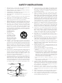
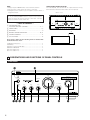
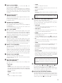
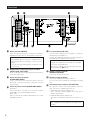
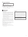
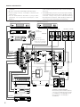
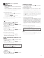
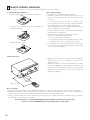
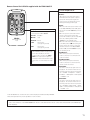
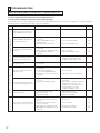
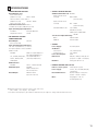
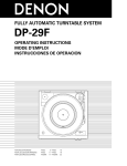
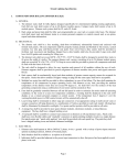
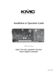
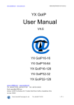
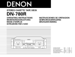
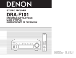
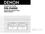
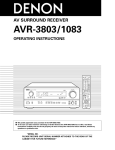
INTEGRATED STEREO AMPLIFIER
PMA-2000IVR
OPERATING INSTRUCTIONS
B
VOLUME
MUTE/STANDBY
INPUT SELECTOR
TAPE-2/MD TAPE-1/CD-R
PHONO
CD
TUNER
DVD/AUX-1 AUX-2/P. DIRECT
POWER
SOURCE DIRECT
¢ ON/STANDBY £ OFF
¢ ON
£ OFF
REMOTE SENSOR
BASS
TREBLE
REC OUT SELECTOR
BALANCE
CD
PHONO
PHONES
TAPE-11 2
COPY
AMP
TUNER
AUX-1
POWER
MUTING
9
AUX-2
8
TRACK
LEFT
FUNCTION
VOLUME
RIGHT
3
2
1
PAUSE
STOP
PLAY
CD
B
REMOTE CONTROL UNIT
RC-858
“SERIAL NO.
PLEASE RECORD UNIT SERIAL NUMBER ATTACHED TO THE REAR OF THE
CABINET FOR FUTURE REFERENCE”
2 SAFETY PRECAUTIONS
CAUTION
CAUTION
TO PREVENT ELECTRIC SHOCK, MATCH WIDE BLADE OF
PLUG TO WIDE SLOT, FULLY INSERT.
RISK OF ELECTRIC SHOCK
DO NOT OPEN
CAUTION:
TO REDUCE THE RISK OF ELECTRIC SHOCK,
DO NOT REMOVE COVER (OR BACK). NO
USER-SERVICEABLE PARTS INSIDE. REFER
SERVICING TO QUALIFIED SERVICE
PERSONNEL.
The lightning flash with arrowhead symbol, within an
equilateral triangle, is intended to alert the user to the
presence of uninsulated “dangerous voltage” within the
product’s enclosure that may be of sufficient magnitude to
constitute a risk of electric shock to persons.
The exclamation point within an equilateral triangle is
intended to alert the user to the presence of important
operating and maintenance (servicing) instructions in the
literature accompanying the appliance.
WARNING: TO REDUCE THE RISK OF FIRE OR ELECTRIC
SHOCK, DO NOT EXPOSE THIS APPLIANCE
TO RAIN OR MOISTURE.
ATTENTION
POUR ÉVITER LES CHOCS ÉLECTRIQUES, INTERODUIRE LA
LAME LA PLUS LARGE DE LA FICHE DANS LA BORNE
CORRESPONDANTE DE LA PRISE ET POUSSER JUSQU’ AU
FOND.
This device complies with Part 15 of the FCC Rules. Operation is subject to
the following two conditions: (1) This device may not cause harmful
interference, and (2) this device must accept any interference received,
including interference that may cause undesired operation.
This Class B digital apparatus meets all requirements of the Canadian
Interference-Causing Equipment Regulations.
Cet appareil numérique de la classe B respecte toutes les exigences du
Règlement sur le matériel brouilleur du Canada.
2 NOTE ON USE
• Do not let foreign objects in the set.
• Keep the set free from moisture, water, and
dust.
• Avoid high temperatures.
Allow for sufficient heat dispersion when
installed on a rack.
• Unplug the power cord when not using the
set for long periods of time.
• Handle the power cord carefully.
Hold the plug when unplugging the cord.
* (For sets with ventilation holes)
• Do not obstruct the ventilation holes.
2
• Do not let insecticides, benzene, and thinner
come in contact with the set.
• Never disassemble or modify the set in any
way.
SAFETY INSTRUCTIONS
1.
2.
3.
4.
5.
6.
7.
8.
9.
10.
11.
12.
Read Instructions – All the safety and operating instructions
should be read before the product is operated.
Retain Instructions – The safety and operating instructions
should be retained for future reference.
Heed Warnings – All warnings on the product and in the
operating instructions should be adhered to.
Follow Instructions – All operating and use instructions should
be followed.
Cleaning – Unplug this product from the wall outlet before
cleaning. Do not use liquid cleaners or aerosol cleaners.
Attachments – Do not use attachments not recommended by
the product manufacturer as they may cause hazards.
Water and Moisture – Do not use this product near water – for
example, near a bath tub, wash bowl, kitchen sink, or laundry
tub; in a wet basement; or near a swimming pool; and the like.
Accessories – Do not place this product on an unstable cart,
stand, tripod, bracket, or table. The product may fall, causing
serious injury to a child or adult, and serious damage to the
product. Use only with a cart, stand, tripod, bracket, or table
recommended by the manufacturer, or sold with the product.
Any mounting of the product should follow the manufacturer’s
instructions, and should use a
mounting accessory
recommended by the
manufacturer.
A product and cart
combination should be
moved with care. Quick
stops, excessive force,
and uneven surfaces may
cause the product and cart
combination to overturn.
Ventilation – Slots and openings in the cabinet are provided for
ventilation and to ensure reliable operation of the product and
to protect it from overheating, and these openings must not be
blocked or covered. The openings should never be blocked by
placing the product on a bed, sofa, rug, or other similar
surface. This product should not be placed in a built-in
installation such as a bookcase or rack unless proper
ventilation is provided or the manufacturer’s instructions have
been adhered to.
Power Sources – This product should be operated only from
the type of power source indicated on the marking label. If
you are not sure of the type of power supply to your home,
consult your product dealer or local power company. For
products intended to operate from battery power, or other
sources, refer to the operating instructions.
Grounding or Polarization – This product may be equipped with
a polarized alternating-current line plug (a plug having one
blade wider than the other). This plug will fit into the power
outlet only one way. This is a safety feature. If you are unable
to insert the plug fully into the outlet, try reversing the plug. If
the plug should still fail to fit, contact your electrician to replace
your obsolete outlet. Do not defeat the safety purpose of the
FIGURE A
EXAMPLE OF ANTENNA GROUNDING
AS PER NATIONAL
ELECTRICAL CODE
ANTENNA
LEAD IN
WIRE
13.
15.
16.
17.
18.
19.
20.
21.
22.
23.
GROUND
CLAMP
ANTENNA
DISCHARGE UNIT
(NEC SECTION 810-20)
ELECTRIC
SERVICE
EQUIPMENT
24.
25.
GROUNDING CONDUCTORS
(NEC SECTION 810-21)
GROUND CLAMPS
Power-Cord Protection – Power-supply cords should be routed
so that they are not likely to be walked on or pinched by items
placed upon or against them, paying particular attention to
cords at plugs, convenience receptacles, and the point where
they exit from the product.
Outdoor Antenna Grounding – If an outside antenna or cable
system is connected to the product, be sure the antenna or
cable system is grounded so as to provide some protection
against voltage surges and built-up static charges. Article 810
of the National Electrical Code, ANSI/NFPA 70, provides
information with regard to proper grounding of the mast and
supporting structure, grounding of the lead-in wire to an
antenna discharge unit, size of grounding conductors, location
of antenna-discharge unit, connection to grounding electrodes,
and requirements for the grounding electrode. See Figure A.
Lightning – For added protection for this product during a
lightning storm, or when it is left unattended and unused for
long periods of time, unplug it from the wall outlet and
disconnect the antenna or cable system. This will prevent
damage to the product due to lightning and power-line surges.
Power Lines – An outside antenna system should not be
located in the vicinity of overhead power lines or other electric
light or power circuits, or where it can fall into such power
lines or circuits. When installing an outside antenna system,
extreme care should be taken to keep from touching such
power lines or circuits as contact with them might be fatal.
Overloading – Do not overload wall outlets, extension cords, or
integral convenience receptacles as this can result in a risk of
fire or electric shock.
Object and Liquid Entry – Never push objects of any kind into
this product through openings as they may touch dangerous
voltage points or short-out parts that could result in a fire or
electric shock. Never spill liquid of any kind on the product.
Servicing – Do not attempt to service this product yourself
as opening or removing covers may expose you to
dangerous voltage or other hazards. Refer all servicing to
qualified service personnel.
Damage Requiring Service – Unplug this product from the
wall outlet and refer servicing to qualified service personnel
under the following conditions:
a) When the power-supply cord or plug is damaged,
b) If liquid has been spilled, or objects have fallen into the
product,
c) If the product has been exposed to rain or water,
d) If the product does not operate normally by following the
operating instructions. Adjust only those controls that are
covered by the operating instructions as an improper
adjustment of other controls may result in damage and will
often require extensive work by a qualified technician to
restore the product to its normal operation,
e) If the product has been dropped or damaged in any way,
and
f) When the product exhibits a distinct change in performance
– this indicates a need for service.
Replacement Parts – When replacement parts are required, be
sure the service technician has used replacement parts
specified by the manufacturer or have the same characteristics
as the original part. Unauthorized substitutions may result in
fire, electric shock, or other hazards.
Safety Check – Upon completion of any service or repairs to
this product, ask the service technician to perform safety
checks to determine that the product is in proper operating
condition.
Wall or Ceiling Mounting – The product should be mounted to
a wall or ceiling only as recommended by the manufacturer.
Heat – The product should be situated away from heat sources
such as radiators, heat registers, stoves, or other products
(including amplifiers) that produce heat.
POWER SERVICE GROUNDING
ELECTRODE SYSTEM
(NEC ART 250, PART H)
NEC - NATIONAL ELECTRICAL CODE
3
NOTE:
1. Always keep the POWER switch on the main unit turned on.
2. Turn the power on and off from the remote control unit.
3. Unplug the power cord when you do not plan to use the unit for a
long period of time.
PRECAUTIONS FOR INSTALLATION
For heat dispersal, leave at least 10 cm of space between the top,
back and sides of this unit and the wall or other components.
✽ 10cm or more
CAUTION:
If only the MUTE/STANDBY LED is lit red, this means that the
power is turned off from the remote control unit. Turn the
power on from the remote control unit.
✽
B
✽
— TABLE OF CONTENTS —
z
DESIGNATIONS AND
FUNCTIONS OF PANEL CONTROLS …………………………4 ~ 7
x
c
v
b
n
CONNECTIONS
✽
…………………………………………………7, 8
OPERATION …………………………………………………………9
✽
REMOTE CONTROL OPERATION ……………………………10, 11
TROUBLESHOOTING ………………………………………………12
SPECIFICATIONS ……………………………………………………13
Please check to make sure the following items are included with
the main unit in the carton:
Wall
(1) Operating Instructions ………………………………………………1
(2) Warranty ………………………………………………………………1
(3) Remote Control Unit (RC-858) ………………………………………1
(4) Batteries R03 (AAA) …………………………………………………2
(5) Power Supply Cord ……………………………………………………1
(6) Service Station List ……………………………………………………1
1 DESIGNATIONS AND FUNCTIONS OF PANEL CONTROLS
Front Panel
!1
!0
B
VOLUME
MUTE/STANDBY
INPUT SELECTOR
TAPE-2/MD TAPE-1/CD-R
PHONO
CD
POWER
SOURCE DIRECT
¢ ON/STANDBY £ OFF
¢ ON
£ OFF
REMOTE SENSOR
BASS
TREBLE
REC OUT SELECTOR
BALANCE
CD
PHONO
TUNER
PHONES
AUX-1
TAPE-11 2
AUX-2
COPY
RIGHT
LEFT
qw e
4
r
t
y
u
i
o
TUNER
DVD/AUX-1 AUX-2/P. DIRECT
q
w
r
t
y
u
i
• AUX-1:
Used to recording component that connected to the
DVD/ AUX-1 terminals.
• AUX-2:
Used to recording component that connected to the AUX2 terminals.
Remote Control Sensor
(REMOTE SENSOR)
This sensor receives the infra-red light transmitted from the
wireless remote control unit.
For remote control, point the wireless remote control unit
towards the sensor.
e
• TUNER:
Used to recording from the tuner.
Power switch (POWER)
When the power switch is turned ON ( ¢ ), the
MUTE/STANDBY LED !1 lights.
When the power switch is turned ON, power is supplied to
the unit. It takes a few seconds after the power is turned
on for the unit to warm up. This is due to the built-in
muting circuit that eliminates noise during the on/off
operation.
NOTE:
Copying is not possible from TAPE-2/MD to TAPE1/CD-R.
o
Headphone jack (PHONES)
This jack is used to plug in the headphones.
(The SPEAKER output is turned off when the headphones
are plugged in.)
To prevent hearing loss, do not raise the volume level
excessively when using headphones.
• TAPE-1/CD-R:
Use this position when using the tape deck, etc.,
connected to the TAPE-1/CD-R terminals.
This knob is used to control the bass quality of the sound.
When the knob is set at the center position, the frequency
characteristics are flattened in the range below 1000 Hz.
The bass is emphasized as the knob is moved off center to
the right (,), and reduced as it is moved to the left (.).
• PHONO:
Use this position when using the record player connected
to the PHONO terminals.
Use the CARTRIDGE selection switch @1 to switch the
sensitivity to correspond to the cartridge type being used.
Treble control (TREBLE)
This knob is used to control the treble quality of the sound.
When the knob is set at the center position, the frequency
characteristics are flattened in the range above 1000 Hz.
The treble is emphasized as the knob is moved off center to
the right (,), and reduced as it is moved to the left (.).
• CD:
Used to listen a compact disc player or other component
that is connected to the CD terminals.
• TUNER:
Used to play a component such as an FM/AM tuner or a
TV tuner that is connected to the TUNER terminals.
Balance control (BALANCE)
This knob is used to adjust the balance between the left
and right channels.
When it is set to the center position, the amplitude of the
amplifier is equal on both sides. If the volume on the right
side is too low, turn the knob to the right (,). If the volume
on the left side is too low, turn the knob to the left (.).
This will achieve an even balance on the left and right sides.
• DVD/AUX-1:
Used to play a component such as a HiFi video player, TV
tuner or tape deck that is connected to the DVD/AUX-1
terminals.
• AUX-2/P. DIRECT:
Used to play a component such as a HiFi video player, TV
tuner or tape deck that is connected to the AUX-2
terminals. And power amp direct terminal is selected by
using the P. DIRECT switch on the back panel.
Volume control (VOLUME)
This knob controls the overall volume level.
Turn the knob to the right (,) to raise the volume and to the
left (.) to lower it.
NOTE:
When selecting the power amp direct terminal,
volume control function of this unit does not work, so
set volume level by the component connecting to this
terminal.
Recording output selector
(REC OUT SELECTOR)
• TAPE-1 1 2:
(COPY)
Use this position when making copies of tapes using two
tape decks. The input signal from the deck connected to
the TAPE-1/CD-R input terminals is fed to the TAPE-2/MD
REC OUT terminals.
• PHONO:
Used to recording from the turntable.
• CD:
Used to recording from the CD player.
Use these to select the program source.
When the switch for the desired program source is
selected, its LED lights. One program source only can be
selected at a time, as follows.
• TAPE-2/MD:
Use this position when using the tape deck, etc.,
connected to the TAPE-2/MD terminals.
Bass control (BASS)
Use this to select the output source for recording onto a
tape deck, etc.
Input selector switch (INPUT SELECTOR)
!0
!1
Source direct switch (SOURCE DIRECT)
The controls (BASS r, TREBLE t and BALANCE y) can
be used when this switch is in the OFF (£) position.
When set to the ON (¢) position, the above controls are by
passed and the signals are input directly to the volume
control circuit, providing high quality sound.
Mute/Standby LED (MUTE/STANDBY)
This LED flashes while the muting circuit is activated when
the power is turned on and when muting is turned on from
the remote control unit, and remains lit (without flashing)
while the power switch q is turned ON (¢).
5
Rear Panel
@1
!2 !3
!2
@0
!4 !5
!9
!6
Inputs terminals (INPUTS)
These are input terminals for CD players, turntables,
AM/FM tuners, tape decks or other playback components.
!7
!6
NOTE:
The PHONO input terminals are equipped with a
short pin-plug. Remove this plug to connect a record
player.
Store the removed short pin-plug in a safe place so as
not to lose it.
!3
Playing and recording input/output terminals
(TAPE-1/CD-R, TAPE-2/MD)
Power amp direct terminals
(POWER AMP DIRECT)
Souurce connected to this terminal is directly fed to the
power amp. set volume level by the component connected
to this terminal.
!5
Power amp direct switch (POWER AMP DIRECT)
ON position:
Power amp direct terminal is selected when INPUT
SELECTOR is set to AUX-2/P. DIRECT position.
OFF position:
AUX-2 is selected when INPUT SELECTOR is set to AUX2/P. DIRECT position.
Pre out terminals (PRE OUT)
Use these when adding a power amplifier, a subwoofer
with built-in power amplifier, etc.
Connect these PRE OUT terminals to the input terminals on
the additional power amplifier, subwoofer, etc.
NOTE:
Signals are outputted from the PRE OUT terminals
even when using headphones.
No signal is outputted when selecting power amp
direct terminal (see o, page 5)
!7
These are playing and recording input/output terminals for
connection to tape decks.
!4
!8
Speaker systems terminals
(SPEAKER SYSTEMS)
Connect the speaker systems here.
!8
!9
AC inlet receptacle (AC IN)
Connect the included power supply cord here.
Do not use any other cord than the provided power supply
cord.
Attachment plug receptacles (AC OUTLETS)
AC outlets are used for connecting amplifier component
units, such as tuner, turntable, tape deck, etc.
• SWITCHED (Total capacity: 120 W / 1 A):
These outlets are turned ON/OFF when main power
switch is turned on/off.
• UNSWITCHED (Capacity: 240 W / 2 A):
This outlet is always ON whether power switch is on or
off.
NOTE:
This equippment may be different according to the
country.
6
@0
Ground terminal (SIGNAL GND)
Connect the turntable’s ground wire here.
NOTE:
This terminal is used to reduce noise when a
turntable, etc., is connected.
It does not provide grounding.
@1
Cartridge selection switch (CARTRIDGE)
This switch is set according to the type of player cartridge
to be used.
Set this switch to MM (£) or MC (¢) according to the
type of cartridge used on your turntable.
2 CONNECTIONS
Connecting the speakers
• Speaker impedance
• When using speaker systems A and B separately, speakers
with an impedance of 4 to 16 Ω/ohms can be connected.
• When biwiring with biwireable speaker system, speakers
with an impedance of 4 to 16 Ω/ohms can be connected.
• Note that when using two sets of speaker systems together
(A + B), use speakers with impedance 8 to 16 Ω/ohms,
using speakers with an impedance other than between 8 to
16 Ω/ohms may cause damages.
Note that this unit is not equipped with a switch for
selecting the speaker system. The A and B speaker output
terminals are connected in parallel.
• The protective circuit may be activated if speakers with
other impedances are connected.
• Be sure to connect the cords between the speaker terminals
and speaker systems with the same polarities (< to <, > to
>). If not, the central sound will be weak and the position of
the different instruments will not be clear, diminishing the
stereo effect.
• When connecting the speakers, be sure that the core wires of
the speaker cords do not stick out from the terminals and
touch other terminals, each other or the rear panel.
• Connecting the speaker cords
q Peel off the sheathing from the end of the cord.
w Twist the core wires.
e Turn the speaker terminal counterclockwise to loosen it.
r Insert the core wires entirely, then turn the terminal
clockwise to tighten it.
CAUTION
Protective Circuit
This set is equipped with a high speed protective circuit.
This circuit protects the internal circuitry from damage due
to large currents flowing when the speaker jacks are not
completely connected or when an output is generated by a
short circuit. This protective circuit’s operation cuts off the
output to the speakers. In such a case, be sure to turn the
power off and check the connections to the speakers.
Then turn the power on again. After muting for several
seconds, the set will operate normally.
NOTE:
NEVER touch the speaker terminals when the power is on.
Doing so could result in electric shocks.
7
Cautions on Connections
• Do not plug in the power cord until all connections are
completed.
• Be sure to connect the left and right channels properly.
• Insert the plugs securely. Incomplete connections can
result in noise.
• Use the SWITCHED AC OUTLETS to plug in audio
components. Do not use them for hair dryers or other
appliances.
DVD player (sound only)
• Note that placing the pin plug cords next to power supply
cords or near power transformers may result in humming or
other noise.
• The PHONO input jacks have an extremely high sensitivity,
so avoid turning up the volume when no pin plug cords are
connected. Doing so may result in induction humming
(booming) from the speakers. When pin plug cords are not
connected, insert the included short-circuit pin plug.
DVD player (sound only)
B
B
Tuner
SPEAKER SYSTEM (A)
SPEAKER SYSTEM (B)
Turntable
(for MC, MM)
LINE OUT
CD player
Ground wire
✽ Connect the ground wire,
but disconnect it if humming
or other noise is generated.
L
R
L
LINE OUT
LINE OUT
LINE OUT
Subwoofer
Power supply cord
LINE OUT (PB)
PRE OUT
AV Center
Power amplifier
Tape deck or MD recorder
LINE IN (REC)
Tape deck or CD-R
LINE IN (REC)
LINE OUT (PB)
8
LINE IN
LINE IN
B
HIGH
HIGH
LOW
LOW
R
L
SPEAKER SYSTEM (BI-WIRING)
When bi-wiring with bi-wireable speakers,
connect the mid and high range terminals
to SYSTEM (A) (or SYSTEM (B)), the low
range terminals to SYSTEM (B) (or
SYSTEM (A)).
R
3 OPERATION (Refer to page 4 and 6)
PREPARATION
1. CHECKING CONNECTIONS
• Make sure that all the connections are proper by referring to
the rear panel.
• Check the polarity (positive and negative) of connections,
and the directivity of stereo separation (right cord to right
channel terminal, and left cord to left channel terminal).
• Check the directivity of pin cord connection.
2. SETTING OF EACH KNOB
• Turn the volume control knob u counterclockwise, to
minimum position.
• Set the rotary knob r, t, y to center position.
• Set SOURCE DIRECT !0 to “OFF (£)”.
After checking the above items, turn on the power, the amplifier
is set in the ready mode in a few seconds.
PLAYING A RECORD
1. Set the CARTRIDGE selection switch @1 “MC (¢)” or “MM
(£)”.
2. Set the INPUT SELECTOR switch o to “PHONO”.
3. Operate the turntable and play the record.
4. Turn the volume u and tone controls r, t, y to yield an
appropriate volume and sound quality.
PLAYING CD PLAYER
1. Set the INPUT SELECTOR switch o to “CD”.
2. Operate the CD player.
3. Turn the volume u and tone controls r, t, y to yield an
appropriate volume and sound quality.
RECEPTION OF RADIO PROGRAMS
1. Set the INPUT SELECTOR switch o to “TUNER”.
2. Operate the tuner to receive a radio program.
3. Turn the volume u and tone controls r, t, y to yield an
appropriate volume and sound quality.
RECORDING WITH TAPE DECK
1. Set the REC OUT SELECTOR switch i to the program
source you wish to record.
2. Play back the program source.
3. Start recording with the component connected to “TAPE1/CD-R” or “TAPE-2/MD”.
• In the PMA-2000IVR, the REC OUT signal and the speaker
(headphone) signal are output via separate circuits so that
knobs and switches related to the tone and volume have no
effect what ever on the sound that is recorded. Also, since the
recording function is selected by the REC OUT SELECTOR
switch i, the free program source can be played through the
speakers (or headphones) even during recording.
• MONITORING THE RECORDING
A recording in progress can be monitored if a tape deck with
three individual heads for recording and playback is used. A
tape deck in which a common head is used for both recording
and playback cannot be used to monitor recording. When a
recording is being made using TAPE-1/CD-R, selecting TAPE1/CD-R with the INPUT SELECTOR will engage the
RECORDING MONITOR and pemit a check of the recording
condition.
COPYING FROM ONE TAPE TO ANOTHER
To copy from TAPE-1/CD-R to TAPE-2/MD, set the REC OUT
SELECTOR switch i to “TAPE-1 1 2”.
NOTE:
Copying is not possible from TAPE-2/MD to TAPE-1/CD-R.
NOTE:
• This amplifier has a full memory back-up system. When the
power is turned on, INPUT SELECTOR o are set to the last
mode set before the power was turned off.
PLAYING AUDIO EQUIPMENT CONNECTED TO AUX
TERMINALS
1. Set the INPUT SELECTOR switch o to “DVD/AUX-1” (AUX-2/
P. DIRECT) position.
2. Operate the Audio equipment Systems.
3. Turn the volume u and tone controls r, t, y to yield an
appropriate volume and sound quality.
NOTE:
If power amp direct switch (BACK PANEL) is set to ON
position, power amp direct terminal is selected when AUX2/P. DIRECT is selected. (see o, page 5)
PLAY BACK WITH TAPE DECK
1. Set the INPUT SELECTOR switch o to “TAPE-1/CD-R” or
“TAPE-2/MD”.
2. Operate the Tape Deck.
3. Turn the volume u and tone controls r, t, y to yield an
appropriate volume and sound quality.
9
4 REMOTE CONTROL OPERATION
The accessory Remote Control Unit is used to control the amplifier from a convenient distance.
(1) Inserting the Dry Cell Batteries
1. Remove the battery cover on the Remote Control Unit.
2. Insert two dry cell batteries as shown in the diagram on
the battery supply unit.
3. Replace the battery cover.
Notes on Battery Usage
• RC-858 uses the size R03 (AAA) dry cell batteries.
• The batteries will need to be replaced approximately once a
year. This will depend upon how often the Remote Control
Unit is used.
• If, in less than a year from the time new batteries were
inserted, the Remote Control Unit fails to operate the Amplifier
from a near-by position, it is time to replace the batteries.
(The included battery is only for verifying operation. Replace it
with a new battery as soon as possible.)
• Insert the batteries properly, following the polarity diagram
inside the battery compartment.
• Batteries are prone to damage and leakage. Therefore:
• Do not mix new batteries with used ones.
• Do not mix different types of batteries.
• Do not jumper opposite poles of the batteries, expose them
to heat, break them open, nor expose them to open fire.
• If the batteries have leaked, remove any traces of battery fluid
from the battery compartment wiping thoroughly with a dry
cloth. Then insert new batteries.
(2) Directions for use
• Operate the Remote Control Unit while pointing it towards the
Remote Control Sensor on the Amplifier as shown in the
diagram on the left.
• The Remote Control Unit can be used at distances up to about
8 meters in a straight line from the amplifier. This distance will
decrease if there are obstructions blocking the infra-red light
transmission or if the Remote Control Unit is not directed
straight at the amplifier.
30°
30°
Approx. 8 meters
Note on operation
• Do not press the operating buttons on the Amplifier and the Remote Control Unit at the same time. This will cause misoperation.
• Operation of the Remote Control Unit will become less effective or erratic if the infrared Remote Control Sensor on the Amplifier is
exposed to strong light or if there are obstructions between the Remote Control Unit and the sensor.
• In case you operate a VCR, TV or other components by remote control, do not operate buttons on two different remote control units
at the same time. This will cause misoperation.
Besides being able to operate the PMA-2000 IVR Integrated-amplifier with this Remote Control Unit,
you can also operate a DENON CD player from this handy Remote Control Unit.
10
Remote Control Unit RC-858 supplied with the PMA-2000IVR
Pre-main Amplifier Block
Use these to control the PMA-2000IVR.
MUTING :
When pressed, the main unit’s power
LED flashes and the speaker output is
turned off. When pressed again, the
mute mode is canceled and the power
LED stops flashing (remaining lit).
AMP
POWER
MUTING
9
8
TRACK
FUNCTION
VOLUME
3
2
1
PAUSE
STOP
PLAY
CD
B
REMOTE CONTROL UNIT
RC-858
CD player Block
Use these to control the CD player
connected to the PMA-2000IVR.
1 PLAY
: Playback
2 STOP
: Stop
3 PAUSE : Pause
8
: Auto search
(to beginning of track)
9
: Auto search
(to beginning of track)
NOTE:
With DENON portable CD players and
some other CD players, the auto
search mode is set when the 8 or
9 button is pressed shortly then
released, and the manual search mode
is set when one of the buttons is held
in.
POWER :
• When the main unit’s power switch is set
to the ON/STANDBY position (¢), press
this to turn the PMA-2000IVR’s power on
and off.
• When the power is turned off from the
remote control unit, the main unit’s
power LED remains lit, but the input LED
turns off, indicating that the PMA2000IVR is in the standby mode.
• When the main unit’s power button is set
to the OFF position (£) after turning the
power off from the remote control unit
and then set back to the ON/STANDBY
position (¢), the PMA-2000IVR is set to
the operating mode.
VOLUME • UP :
While this is pressed, the main unit’s
volume control turns clockwise and the
volume increases.
VOLUME ª DOWN :
While this is pressed, the main unit’s
volume control turns counterclockwise
and the volume decreases.
FUNCTION • :
Use this to select the program source to
be played. The function switches in the
following order each time this is pressed:
CD / TUNER / DVD/AUX-1 / AUX-2/
P. DIRECT / TAPE-2/MD / TAPE-1/CD-R
/ PHONO / CD
FUNCTION ª :
Use this to select the program source to
be played. The function switches in the
following order each time this is pressed:
CD / PHONO / TAPE-1/CD-R / TAPE2/MD / AUX-2/P. DIRECT / DVD/AUX-1
/ TUNER / CD
• The RC-858 Remote Control Unit can control CD players manufactured by DENON.
• Note that operation may not be possible for some models.
CAUTION:
Some of the functions of the PMA-2000IVR can also be controlled with the remote control units included with other DENON premain amplifiers.
11
5 TROUBLESHOOTING
Check the following before assuming there is a problem with the set.
1. Are all connections proper ?
2. Is the set being operated as described in the operating instructions ?
3. Are the speakers and input components being operated properly ?
If the set does not seem to be operating properly, check the points listed below. If these points do not apply, the set may be damaged.
Turn off the power immediately and contact your store of purchase.
Remote control unit.
Problems occurring when playing records.
Common problems arising when listening to the CD,
records, tapes, and FM broadcasts, etc.
Symptom
12
MUTE/STANDBY LED does not
light and no sound is produced
when POWER switch is turned
on.
Cause
Measures
Page
• Power supply cord is not connected.
• Check that the cord is plugged in.
• Speaker cords not properly
connected.
• INPUT SELECTOR is not set to
proper position.
• VOLUME control turned down.
• Connect securely.
7, 8
• Set to the proper position.
5, 9
• Set to an appropriate level.
5, 9
• Speaker cords not properly
connected.
• Input cords not are properly connected.
• Left/right balance improperly
adjusted.
• Connect securely.
7, 8
• Connect securely.
• Adjust the BALANCE control.
8
5, 9
• Tuner or record output is different.
• Adjust the tuner output to the
turntable’s output (if the tuner is
equipped with an output control).
–
Positions of instruments inverted
for stereo sources.
• Left and right speakers or input cords
the inverted.
• Check the left/right connections.
7, 8
• Connect securely.
8
Booming sound produced when
playing records.
• Turntable’s ground wire is not
connected.
• Input cords are not properly
connected to PHONO terminals.
• Influence from a TV or VCR near the
turntable.
• Connect securely.
8
• Change the position of installation.
–
• Turntable and speaker systems are
too close.
• Floor is soft and vibrates easily.
• Move speaker systems as far away
as possible.
• Use cushions to absorb the vibrations
transmitted from the floor to the
speakers. If the turntable does not
include insulators, use audio
insulators, available in stores.
–
Sound is distorted.
• Stylus pressure is too light.
• Dirt on tip of stylus.
• Defective cartridge.
• Apply proper pressure.
• Check the tip of the stylus.
• Replace the cartridge.
–
–
–
• Replace with new batteries.
• Move closer.
10
10
This unit is not operated properly
when remote control unit is used.
• Batteries are dead.
• Remote control unit is too far from
this unit.
• Obstacle between this unit and
remote control unit.
• Different button is being pressed.
• < and > ends of battery is inserted
in reverse.
• Remove obstacle.
10
• Press the proper button.
• Insert batteries properly.
11
10
MUTE/STANDBY LED lights but
no sound is produced.
Sound is not produced from one
side only.
Volume level is different when
listening to tuner and records.
Howling produced when volume
is turned up while playing records.
8
–
6 SPECIFICATIONS
• POWER AMPLIFIER SECTION
Rated Output Power:
Both channel driven
(8 Ω/ohms Load)
80 W + 80 W
20 Hz to 20 kHz, T.H.D. 0.07 %
(4 Ω/ohms Load)
160 W + 160 W
DIN, 1 kHz, T.H.D. 0.7 %
Total Harmonic Distortion: 0.01 %
(–3 dB at rated output, 8 Ω/ohms) (1 kHz)
Input Sensitivity/Input Impedance:
P. DIRECT:
0.9 V/47 kΩ/kohms
Amplification factor:
29 dB
• PRE AMPLIFIER SECTION
PHONO EQUALIZER
Rated Output:
150 mV
(Recout Terminal)
Input Sensitivity/Input Impedance:
The value in parentheses ( ) refers to
the input impedance when SOURCE
DIRECT is ON.
PHONO:
MM: 2.5 mV/47 kΩ/kohms
MC: 200 µV/100 Ω/ohms
CD, TUNER, DVD/AUX-1, 135 mV/47 kΩ/kohms
AUX-2, TAPE-1/CD-R,
(135 mV/12 kΩ/kohms)
TAPE-2/MD
RIAA Deviation:
PHONO:
20 Hz ~ 20 kHz ±0.5 dB
Maximum Input:
PHONO
MM: 130 mV/1 kHz
MC: 10 mV/1 kHz
Rated Output:
PRE PUT: 0.9 V
(Input CD 135 mV)
• OVERALL CHARACTERISTICS
SN Ratio (IHF A Network): PHONO
(input terminals shortcircuited)
MM: 89 dB
(at 5 mV input)
(input terminals shortcircuited)
MC: 74 dB
(at 0.5 mV input)
SOURCE-DIRECT: ON
CD, TUNER,
DVD/AUX-1, AUX-2,
TAPE-1/CD-R, TAPE-2/MD:
108 dB
Tone Control Adjustable Range:
BASS:
100 Hz ±8 dB
TREBLE:
10 kHz ±8 dB
• OTHERS
Power Supply:
AC Outlets:
Switched x 2:
Unswitched x 1:
Power Consumption:
Dimensions:
Net Mass:
AC 120 V, 60 Hz
1 A / 120 W (Total)
2 A / 240 W
6.0 A
434 (W) x 180 (H) x 478 (D) mm
(17-3/32” x 7-5/64” x 18-13/16”)
24.0 kg (52 lbs 14.7 oz)
• REMOTE CONTROL UNIT (RC-858)
Remote control system:
Infrared pulse system
Power supply:
3 V DC, Two size R03 (AAA) dry
cell batteries
External dimensions:
56 (W) x 105 (H) x 19 (D) mm
(2-3/16” x 4-1/8” x 23/32”)
Mass:
70 g (Approx. 2.47 oz)
(including batteries)
✽ Maximum dimensions include controls, jacks, and covers.
(W) = width, (H) = height, (D) = depth
• For improvement purposes, specifications and functions are subject to change without advanced notice.
13
MEMO
14
MEMO
15
16-11, YUSHIMA 3-CHOME, BUNKYOU-KU, TOKYO 113-0034, JAPAN
Telephone: (03) 3837-5321
Printed in Japan 511 3917 001