1
Dell_PERC6.1_UG.book Page 1 Wednesday, April 15, 2009 4:18 PM
Dell™ PERC 6/i, PERC 6/E and CERC 6/i
User’s Guide
Model UCP-60 , UCP-61, and UCC-60
w w w. d e l l . c o m | s u p p o r t . d e l l . c o m
Dell_PERC6.1_UG.book Page 2 Wednesday, April 15, 2009 4:18 PM
Notes, Notices, and Cautions
NOTE: A NOTE indicates important information that helps you make better use of
your system.
NOTICE: A NOTICE warns against either potential damage to hardware or of data
and tells you how to avoid the problem.
CAUTION: A CAUTION indicates a potential for property damage, personal injury,
or death.
NOTE: Refer to the Product Information Guide that came with your system for
complete information about U.S. Terms and Conditions of Sale, Limited Warranties,
and Returns, Export Regulations, Software License Agreement, Safety,
Environmental and Ergonomic Instructions, Regulatory Notices, and Recycling
Information.
____________________
Information in this document is subject to change without notice.
© 2007–2008 Dell Inc. All rights reserved.
Reproduction of these materials in any manner whatsoever without the written permission of Dell Inc.
is strictly forbidden.
Trademarks used in this text: Dell, the DELL logo, PowerEdge, PowerVault, Dell Precision, and
OpenManage are trademarks of Dell Inc.; MegaRAID is a registered trademark of LSI Corporation;
Microsoft, MS-DOS, Windows Server, Windows, and Windows Vista are either trademarks or registered
trademarks of Microsoft Corporation in the United States and/or other countries; Citrix XenServer is
a trademark of Citrix Systems, Inc. and/or one or more of its subsidiaries, and may be registered in
the U.S. Patent and Trademark Office and in other countries; VMware is a registered trademark of
VMware, Inc. in the United States and/or other jurisdictions; Solaris is a trademark of
Sun Microsystems, Inc.; Intel is a registered trademark of Intel Corporation or its subsidiaries in
the United States or other countries; Novell and NetWare are registered trademarks, and SUSE is
a registered trademark of Novell, Inc. in the United States and other countries; Red Hat and Red Hat
Enterprise Linux are registered trademarks of Red Hat, Inc.
Other trademarks and trade names may be used in this document to refer to either the entities claiming
the marks and names or their products. Dell Inc. disclaims any proprietary interest in trademarks and
trade names other than its own.
Model UCP-60, UCP-61, and UCC-60
July 2008
P/N P412J
Rev. A00
Dell_PERC6.1_UG.book Page 3 Wednesday, April 15, 2009 4:18 PM
Contents
A CAUTION: Safety Instructions .
SAFETY: General .
. . . . . . . .
11
. . . . . . . . . . . . . . . . . . . .
11
SAFETY: When Working Inside Your System
. . . . . .
12
Protecting Against Electrostatic Discharge
. . . . . .
12
. . . . . . . . . . . . . . . .
13
. . . . . . . . . . . . . . . . . . . . . . . . .
15
SAFETY: Battery Disposal
1
Overview
Scope of the User’s Guide .
. . . . . . . . . . . . . . .
. . . . .
15
. . . . . . . . . . . . . . . . . .
16
PERC 6 and CERC 6/i Controller Descriptions .
PCI Architecture
Operating System Support .
RAID Description
. . . . . . . . . . . . . . .
16
. . . . . . . . . . . . . . . . . . . .
17
Summary of RAID Levels .
RAID Terminology .
2
15
. . . . . . . . . . . . .
17
. . . . . . . . . . . . . . . . .
18
About PERC 6 and CERC 6i
Controllers . . . . . . . . . . . .
. . . . . . . . . . .
PERC 6 and CERC 6i Controller Features
Using the SMART Feature .
21
. . . . . . . .
21
. . . . . . . . . . . . . . .
24
Contents
3
Dell_PERC6.1_UG.book Page 4 Wednesday, April 15, 2009 4:18 PM
Initializing Virtual Disks .
. . . . . . . . . . . . . . . .
Background Initialization .
. . . . . . . . . . . . .
. . . . . . . . .
26
Fast Inititialization of Virtual Disks
. . . . . . . . .
26
. . . . . . . . . . . . . . . . . . .
26
Disk Roaming.
. . . . . . . . . . . . . . . . . . . . . .
27
Disk Migration
. . . . . . . . . . . . . . . . . . . . . .
27
Compatibility With Virtual Disks Created
on PERC 5 Controllers . . . . . . . . . . .
. . . . .
28
Compatibility With Virtual Disks Created
on SAS 6/iR Controllers . . . . . . . . . .
. . . . .
29
. . . . . . .
29
. . . . . . . . . . . . . . . . . .
30
Migrating Virtual Disks from SAS 6/iR
to PERC 6 and CERC 6i . . . . . . . .
Battery Management .
. . . . . . . . . . .
31
. . . . . . . . . . . . . . . .
31
Battery Warranty Information
Battery Learn Cycle .
Virtual Disk Write Cache Policies .
. . . . . . . . . . .
Conditions Under Which
Write-Back is Employed
32
. . . . . . . . . .
32
. . . . . . . . . . . . . .
33
Write-Back and Write-Through.
Conditions Under Which
Write-Through is Employed .
. . . . . . . . . . . .
Conditions Under Which Forced
Write-Back With No Battery is Employed
33
. . . . .
33
Virtual Disk Read Policies .
. . . . . . . . . . . . . . .
33
Reconfiguring Virtual Disks
. . . . . . . . . . . . . . .
34
. . . . . . . . . . . . . . . .
36
Fault Tolerance Features .
Physical Disk Hot Swapping
. . . . . . . . . . . .
Failed Physical Disk Detection
Contents
25
Full Inititialization of Virtual Disks.
Consistency Checks
4
25
. . . . . . . . . . .
36
37
Dell_PERC6.1_UG.book Page 5 Wednesday, April 15, 2009 4:18 PM
Redundant Path With Load
Balancing Support . . . . .
. . . . . . . . . . . .
37
Using Replace Member and
Revertible Hot Spares . . .
. . . . . . . . . . . .
37
. . . . . . . . . . . . . . . . . . . . . . .
38
Patrol Read .
3
Patrol Read Feature
. . . . . . . . . . . . . . . .
38
Patrol Read Modes .
. . . . . . . . . . . . . . . .
39
Installaing and Configuring
Hardware . . . . . . . . . . . . . .
. . . . . . . . . .
Installing the PERC 6/E and PERC 6/i Adapters
Installing the Transportable Battery
Backup Unit (TBBU) for PERC 6/E . .
. . . . .
41
. . . . . . . . . .
45
Installing the DIMM on a PERC 6/E Adapter
Transferring a TBBU Between Controllers
. . . . . .
47
. . . . . . .
49
Removing the PERC 6/E and PERC 6/i Adapters .
Removing the DIMM and Battery from
a PERC 6/E Adapter . . . . . . . . . .
. . . .
50
. . . . . . . . .
53
Disconnecting the BBU from a PERC 6/i Adapter
or a PERC 6/i Integrated Controller . . . . . . . .
Setting up Redundant Path Support
on the PERC 6/E Adapter . . . . . . .
. . .
55
. . . . . . . . . .
56
Removing and Installing the CERC 6/i
Modular Storage Controller Card
(Service-Only Procedure) . . . . . . .
Installing the Modular Storage
Controller Card . . . . . . . . .
41
. . . . . . . . .
59
. . . . . . . . . .
61
Contents
5
Dell_PERC6.1_UG.book Page 6 Wednesday, April 15, 2009 4:18 PM
4
Installing the Drivers .
Installing Windows Driver .
. . . . . . . . . . . . . .
. . . . . . . . . . . . . . .
Creating the Driver Media
. . . . . . . . . . . . .
Pre-Installation Requirements
. . . . . . . . . . .
Installing the Driver During a Windows
Server 2003 or Windows XP
Operating System Installation. . . . . .
Installing the Driver During a
Windows Server 2008 or
Windows Vista Installation . .
64
64
. . . . . .
66
. . . . . . . . . . .
66
. . . . . .
67
Updating an Existing Windows
Server 2003, Windows Server 2008,
Windows XP, or Windows Vista Driver .
. . . . . .
68
. . . . . . . . . . . . . . . . .
69
Installing Red Hat Enterprise Linux
Operating Systems using the
Driver Update Diskette . . . . . . .
. . . . . . . .
Installing SUSE Linux Enterprise
Server Using the Driver Update Diskette .
Installing Solaris Driver
71
. . . . .
71
. . . . . . . . . . . .
72
. . . . . . . . . . . . . . . . .
73
Installing the RPM Package
With DKMS Support . . . .
Installing Solaris 10 on a PowerEdge
System Booting From a PERC 6 and
CERC 6i Controller . . . . . . . . . . .
Adding/Updating the Driver to
an Existing System . . . . . .
Contents
64
Installing a Windows Server 2003,
Windows Server 2008, Windows Vista,
or Windows XP Driver for
a New RAID Controller . . . . . . . . .
Installing Linux Driver .
6
63
. . . . . . .
74
. . . . . . . . . . .
74
Dell_PERC6.1_UG.book Page 7 Wednesday, April 15, 2009 4:18 PM
Installing NetWare Driver .
. . . . . . . . . . . . . . .
Installing the NetWare Driver in
a New NetWare System . . . .
. . . . . . . . . .
Installing or Updating the NetWare
Driver in an Existing NetWare System
5
. . . . . . .
Configuring and Managing RAID .
76
77
. . . . . . .
77
. . . . . . . . . . . .
77
. . . . . . . . . . . . .
78
. . . . . . . . . . . . . . .
79
Dell SAS RAID Storage Manager
RAID Configuration Functions .
. . . . . .
79
. . . . . . . . . .
80
Entering the BIOS Configuration Utility .
Exiting the Configuration Utility .
. . . . . . . . . . . . .
80
. . . . . . . . . . . . . .
83
. . . . . . . . . . . . . . . .
85
Menu Navigation Controls
Setting Up Virtual Disks.
Virtual Disk Management
75
. . . . . .
Dell OpenManage Storage Management .
BIOS Configuration Utility .
75
Creating Virtual Disks .
. . . . . . . . . . . . . . .
Initializing Virtual Disks .
. . . . . . . . . . . . . .
Checking Data Consistency
. . . . . . . . . . . .
Importing or Clearing Foreign
Configurations Using the VD Mgmt Menu
88
88
. . . . .
89
. . . . . . . .
90
. . . . . . . . . . . .
93
Importing or Clearing
Foreign Configurations Using the
Foreign Configuration View Screen
Managing Preserved Cache
85
. . . . . . . . .
94
Deleting Virtual Disks .
. . . . . . . . . . . . . . .
95
Deleting Disk Groups .
. . . . . . . . . . . . . . .
95
Managing Dedicated Hot Spares.
Resetting the Configuration
. . . . . . . . . . . .
BIOS Configuration Utility Menu Options.
. . . . .
Contents
96
96
7
Dell_PERC6.1_UG.book Page 8 Wednesday, April 15, 2009 4:18 PM
Physical Disk Management
Setting LED Blinking
. . . . . . . . . . . . . .
104
. . . . . . . . . . . . . . .
104
Creating Global Hot Spares .
. . . . . . . . . . .
Replacing an Online Physical Disk
105
. . . . . . . .
106
. . . . . . .
107
. . . . . . . . .
107
. . . . . . . . . . . . . . . .
108
Stopping Background Initialization .
Performing a Manual Rebuild of
an Individual Physical Disk . . .
Controller Management
Enabling Boot Support
. . . . . . . . . . . . . .
Enabling BIOS Stop on Error
. . . . . . . . . . .
Troubleshooting .
. . . . . . . . . . . . . . . . . .
111
. . . . . . . . . . . . . . . . .
Virtual Disks Degraded
117
. . . . . . . . . . . . . . . . . . . . .
118
General Problems
. . . . . . . . . . . . . . . . . .
118
. . . . . . . . . . . . . . . . . . .
119
Physical Disk Related Issues
. . . . . . . . . . . . .
Physical Disk Failures and Rebuilds
Contents
120
. . . . . . . . .
121
. . . . . . . . . . . . . . . . . . . . .
123
Replace Member Errors
8
111
. . . . . . . . . . . . . . . .
Pinned Cache State
SMART Errors
109
110
Post Error Messages .
Memory Errors
108
. . . . . . .
Restoring Factory Default Settings .
6
104
. . .
Removing Global or Dedicated Hot Spares .
. . . . . . . . . . . . . . . .
124
Dell_PERC6.1_UG.book Page 9 Wednesday, April 15, 2009 4:18 PM
Linux Operating System Errors
Controller LED Indicators
. . . . . . . . . . . . .
125
. . . . . . . . . . . . . . . .
127
Drive Carrier LED Indicators .
B Regulatory Notices
128
. . . . . . . . . . . . . .
. . . . . . . . . . . . . . . .
C Corporate Contact Details
(Taiwan Only) . . . . . . . . . .
. . . . . . . . . .
131
133
Contents
9
Dell_PERC6.1_UG.book Page 10 Wednesday, April 15, 2009 4:18 PM
10
Contents
Dell_PERC6.1_UG.book Page 11 Wednesday, April 15, 2009 4:18 PM
CAUTION: Safety Instructions
Use the following safety guidelines to help ensure your own personal safety and to help protect
your system and working environment from potential damage.
CAUTION: There is a danger of a new battery exploding if it is incorrectly installed.
Replace the battery only with the same or equivalent type recommended by the
manufacturer. Refer to "SAFETY: Battery Disposal" on page 13.
NOTE: Refer to the safety regulations and warnings stated in the documentation that ships
with your Dell™ workstation.
SAFETY: General
•
Observe and follow service markings. Do not service any product except as explained in
your user documentation. Opening or removing covers that are marked with the triangular
symbol with a lightning bolt may expose you to electrical shock. Components inside these
compartments should be serviced only by a trained service technician.
•
If any of the following conditions occur, unplug the product from the electrical outlet and
replace the part or contact your trained service provider:
–
The power cable, extension cable, or plug is damaged.
–
An object has fallen into the product.
–
The product has been exposed to water.
–
The product has been dropped or damaged.
–
The product does not operate correctly when you follow the operating instructions.
•
Use the product only with approved equipment.
•
Operate the product only from the type of external power source indicated on the
electrical ratings label. If you are not sure of the type of power source required, consult
your service provider or local power company.
•
Handle batteries carefully. Do not disassemble, crush, puncture, short external contacts,
dispose of in fire or water, or expose batteries to temperatures higher than
60 degrees Celsius (140 degrees Fahrenheit). Do not attempt to open or service batteries;
replace batteries only with batteries designated for the product.
SAFETY: General
11
Dell_PERC6.1_UG.book Page 12 Wednesday, April 15, 2009 4:18 PM
SAFETY: When Working Inside Your System
Before you remove the system covers, perform the following steps in the sequence indicated.
CAUTION: Except as expressly otherwise instructed in Dell documentation, only trained
service technicians are authorized to remove the system cover and access any of the
components inside the system.
NOTICE: To help avoid possible damage to the system board, wait 5 seconds after turning
off the system before removing a component from the system board or disconnecting a
peripheral device.
1 Turn off the system and any devices.
2 Ground yourself by touching an unpainted metal surface on the chassis before touching
anything inside the system.
3 While you work, periodically touch an unpainted metal surface on the chassis to dissipate any
static electricity that might harm internal components.
4 Disconnect your system and devices from their power sources. To reduce the potential of
personal injury or shock, disconnect any telecommunication lines from the system.
In addition, take note of these safety guidelines when appropriate:
•
When you disconnect a cable, pull on its connector or on its strain-relief loop, not on the
cable itself. Some cables have a connector with locking tabs; if you are disconnecting this
type of cable, press in on the locking tabs before disconnecting the cable. As you pull
connectors apart, keep them evenly aligned to avoid bending any connector pins. Also,
before you connect a cable, make sure that both connectors are correctly oriented and
aligned.
•
Handle components and cards with care. Do not touch the components or contacts on a
card. Hold a card by its edges or by its metal mounting bracket. Hold a component such as
a microprocessor chip by its edges, not by its pins.
Protecting Against Electrostatic Discharge
Electrostatic discharge (ESD) events can harm electronic components inside your computer.
Under certain conditions, ESD may build up on your body or an object, such as a peripheral, and
then discharge into another object, such as your computer. To prevent ESD damage, you should
discharge static electricity from your body before you interact with any of your computer’s internal
electronic components, such as a memory module. You can protect against ESD by touching a
metal grounded object (such as an unpainted metal surface on your computer’s I/O panel) before
you interact with anything electronic. When connecting a peripheral (including handheld digital
assistants) to your computer, you should always ground both yourself and the peripheral before
connecting it to the computer. In addition, as you work inside the computer, periodically touch
an I/O connector to remove any static charge your body may have accumulated.
12
SAFETY: General
Dell_PERC6.1_UG.book Page 13 Wednesday, April 15, 2009 4:18 PM
You can also take the following steps to prevent damage from electrostatic discharge:
•
When unpacking a static-sensitive component from its shipping carton, do not remove the
component from the antistatic packing material until you are ready to install the
component. Just before unwrapping the antistatic package, be sure to discharge static
electricity from your body.
•
When transporting a sensitive component, first place it in an antistatic container or
packaging.
•
Handle all electrostatic sensitive components in a static-safe area. If possible, use antistatic
floor pads and work bench pads.
SAFETY: Battery Disposal
Your system may use a nickel-metal hydride (NiMH), lithium coin-cell, and/or a
lithium-ion battery. The NiMH, lithium coin-cell, and lithium-ion batteries are
long-life batteries, and it is very possible that you will never need to replace them.
However, should you need to replace them, refer to the instructions included in the
section "Configuring and Managing RAID" on page 77.
Do not dispose of the battery along with household waste. Contact your local waste
disposal agency for the address of the nearest battery deposit site.
NOTE: Your system may also include circuit cards or other components that contain
batteries. These batteries must also be disposed of in a battery deposit site. For information
about such batteries, refer to the documentation for the specific card or component.
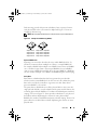
Taiwan Battery Recycling Mark
SAFETY: General
13
Dell_PERC6.1_UG.book Page 14 Wednesday, April 15, 2009 4:18 PM
14
SAFETY: General
Dell_PERC6.1_UG.book Page 15 Wednesday, April 15, 2009 4:18 PM
Overview
The Dell™ PowerEdge™ Expandable RAID Controller (PERC) 6 family of
controllers and the Dell Cost-Effective RAID Controller (CERC) 6/i offer
redundant array of independent disks (RAID) control capabilities. The PERC 6
and CERC 6/i Serial Attached SCSI(SAS) RAID controllers support
Dell-qualified SAS and SATA devices. The controllers are designed to provide
reliability, high performance, and fault-tolerant disk subsystem management.
Scope of the User’s Guide
This user’s guide for the PERC 6 and CERC 6/i controllers documents the
following topics:
•
Overview
•
About PERC 6 and CERC 6/i controllers
•
Hardware installation and configuration
•
Driver installation
•
RAID configuration and management
•
Troubleshooting
PERC 6 and CERC 6/i Controller Descriptions
The following list describes each type of controller:
•
The PERC 6/E adapter with two external x4 SAS ports and a transportable
battery backup unit (TBBU)
•
The PERC 6/i adapter with two internal x4 SAS ports with or without a
battery backup unit, depending on the system
•
The PERC 6/i Integrated controller with two internal x4 SAS ports and a
battery backup unit
•
The CERC 6/i modular storage controller with one internal x4 SAS port
and no battery backup unit
NOTE: The CERC 6/i modular storage controller is a custom form-factor card for
PowerEdge M-Series Modular systems.
Overview
15
Dell_PERC6.1_UG.book Page 16 Wednesday, April 15, 2009 4:18 PM
Each controller supports up to 64 virtual disks.
NOTE: The number of virtual disks supported by the PERC 6/i and the CERC 6/i
cards is limited by the configuration supported by the system.
PCI Architecture
PERC 6 controllers support a Peripheral Component Interconnect
Express (PCI-E) x8 host interface. CERC 6/i Modular controller supports
a PCI-E x4 host. PCI-E is a high-performance input/output (I/O) bus
architecture designed to increase data transfers without slowing down the
Central Processing Unit (CPU).
Operating System Support
The PERC 6 and CERC 6/i controllers support the following operating
systems:
•
Citrix® XenServer Dell Edition
•
Microsoft® Windows Server® 2003
•
Microsoft Windows XP
•
Microsoft Windows Vista™
•
Microsoft Windows Server 2008 (including Hyper-V virtualization)
•
Novell® NetWare® 6.5
•
Red Hat® Enterprise Linux® Version 4 Update 5 and Red Hat Enterprise
Linux Version 5
•
Solaris™ 10 (64-bit)
•
SUSE® Linux Enterprise Server Version 9 (64-bit) and SUSE Linux
Enterprise Server Version 10 (64-bit)
•
VMWare® ESX 3.5 and 3.5i
NOTE: Windows XP and Windows Vista are supported with a PERC 6 controller
only when the controller is installed in a Dell Precision™ workstation.
NOTE: For the latest list of supported operating systems and driver installation
instructions, see the system documentation located at the Dell Support website at
support.dell.com. For specific operating system service pack requirements, see the
Drivers and Downloads section on the Dell Support site at support.dell.com.
16
Overview
Dell_PERC6.1_UG.book Page 17 Wednesday, April 15, 2009 4:18 PM
RAID Description
RAID is a group of independent physical disks that provides high performance by
increasing the number of drives used for saving and accessing data. A RAID disk
subsystem improves I/O performance and data availability. The physical disk
group appears to the host system either as a single storage unit or multiple logical
units. Data throughput improves because several disks are accessed
simultaneously. RAID systems also improve data storage availability and fault
tolerance. Data loss caused by a physical disk failure can be recovered by rebuilding
missing data from the remaining physical disks containing data or parity.
NOTICE: In the event of a physical disk failure, a RAID 0 virtual disk fails, resulting in
data loss.
Summary of RAID Levels
RAID 0 uses disk striping to provide high data throughput, especially for large
files in an environment that requires no data redundancy.
RAID 1 uses disk mirroring so that data written to one physical disk is
simultaneously written to another physical disk. RAID 1 is good for small
databases or other applications that require small capacity, but also require
complete data redundancy.
RAID 5 uses disk striping and parity data across all physical disks (distributed
parity) to provide high data throughput and data redundancy, especially for
small random access.
RAID 6 is an extension of RAID 5 and uses an additional parity block. RAID 6
uses block-level striping with two parity blocks distributed across all member
disks. RAID 6 provides protection against double disk failures and failures
while a single disk is rebuilding. If you are using only one array, deploying
RAID 6 is more effective than deploying a hot spare disk.
RAID 10, a combination of RAID 0 and RAID 1, uses disk striping across
mirrored disks. It provides high data throughput and complete data redundancy.
RAID 10 can support up to eight spans, and up to 32 physical disks per span.
RAID 50, a combination of RAID 0 and RAID 5, uses distributed data parity
and disk striping and works best with data that requires high system availability,
high request rates, high data transfers, and medium-to-large capacity.
RAID 60 is a combination of RAID 6 and RAID 0, a RAID 0 array is striped
across RAID 6 elements. RAID 60 requires at least 8 disks.
Overview
17
Dell_PERC6.1_UG.book Page 18 Wednesday, April 15, 2009 4:18 PM
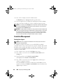
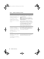
RAID Terminology
Disk Striping
Disk striping allows you to write data across multiple physical disks instead of
just one physical disk. Disk striping involves partitioning each physical disk
storage space into stripes of the following sizes: 8 KB, 16 KB, 32 KB, 64 KB,
128 KB, 256KB, 512KB, and 1024KB. These stripes are interleaved in a
repeated sequential manner. The part of the stripe on a single physical disk is
called a stripe element.
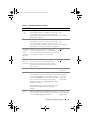
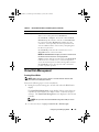
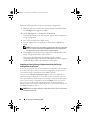
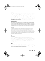
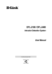
For example, in a four-disk system using only disk striping (used in RAID
level 0), segment 1 is written to disk 1, segment 2 is written to disk 2, and
so on. Disk striping enhances performance because multiple physical disks are
accessed simultaneously, but disk striping does not provide data redundancy.
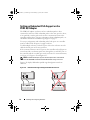
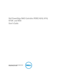
Figure 2-1 shows an example of disk striping.
Figure 2-1.
Example of Disk Striping (RAID 0)
Stripe element 1
Stripe element 5
Stripe element 9
Stripe element 2
Stripe element 6
Stripe element 10
Stripe element 3
Stripe element 7
Stripe element 11
Stripe element 4
Stripe element 8
Stripe element 12
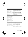
Disk Mirroring
With mirroring (used in RAID 1), data written to one disk is simultaneously
written to another disk. If one disk fails, the contents of the other disk can be
used to run the system and rebuild the failed physical disk. The primary
advantage of disk mirroring is that it provides 100 percent data redundancy.
Because the contents of the disk are completely written to a second disk, it
does not matter if one of the disks fails. Both disks contain the same data at
all times. Either of the physical disks can act as the operational physical disk.
18
Overview
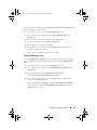
Dell_PERC6.1_UG.book Page 19 Wednesday, April 15, 2009 4:18 PM
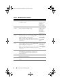
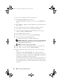
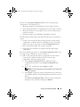
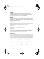
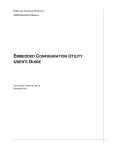
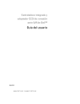
Disk mirroring provides 100 percent redundancy, but is expensive because
each physical disk in the system must be duplicated. Figure 2-2 shows an
example of disk mirroring.
NOTE: Mirrored physical disks improve read performance by read load balance.
Figure 2-2. Example of Disk Mirroring (RAID 1)
Stripe element 1
Stripe element 2
Stripe element 3
Stripe element 4
Stripe element 1 Duplicated
Stripe element 2 Duplicated
Stripe element 3 Duplicated
Stripe element 4 Duplicated
Spanned RAID Levels
Spanning is a term used to describe the way in which RAID levels 10, 50,
and 60 are constructed from multiple sets of basic, or simple RAID levels.
For example, a RAID 10 has multiple sets of RAID 1 arrays where each RAID 1
set is considered a span. Data is then striped (RAID 0) across the RAID 1
spans to create a RAID 10 virtual disk. If you are using RAID 50 or RAID 60,
you can combine multiple sets of RAID 5 and RAID 6 together with striping.
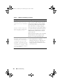
Parity Data
Parity data is redundant data that has been generated to provide fault
tolerance within certain RAID levels. In the event of a drive failure the parity
data can be used by the controller to regenerate user data. Parity data is
present for RAID 5, 6, 50, and 60.
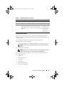
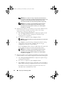
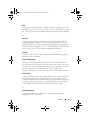
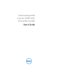
The parity data is distributed across all the physical disks in the system. If a
single physical disk fails, it can be rebuilt from the parity and the data on the
remaining physical disks. RAID level 5 combines distributed parity with disk
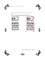
striping, as shown in Figure 2-3. Parity provides redundancy for one physical
disk failure without duplicating the contents of entire physical disks.
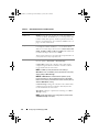
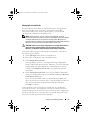
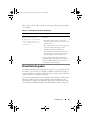
RAID level 6 combines dual distributed parity with disk striping. This level of
parity allows for two disk failures without duplicating the contents of entire
physical disks.
Overview
19
Dell_PERC6.1_UG.book Page 20 Wednesday, April 15, 2009 4:18 PM
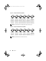
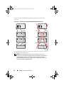
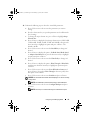
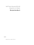
Figure 2-3.
Example of Distributed Parity (RAID 5)
Stripe element 1
Stripe element 7
Stripe element 13
Stripe element 19
Stripe element 25
Parity (26–30)
Stripe element 2
Stripe element 8
Stripe element 3 Stripe element 4 Stripe element 5
Stripe element 9 Stripe element 10 Parity (6–10)
Stripe element 14 Stripe element 15 Parity (11–15) Stripe element 11
Stripe element 20 Parity (16–20) Stripe element 16 Stripe element 17
Parity (21–25) Stripe element 21 Stripe element 22 Stripe element 23
Stripe element 26 Stripe element 27 Stripe element 28 Stripe element 29
Parity (1–5)
Stripe element 6
Stripe element 12
Stripe element 18
Stripe element 24
Stripe element 30
NOTE: Parity is distributed across multiple physical disks in the disk group.
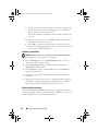
Figure 2-4.
Example of Dual Distributed Parity (RAID 6)
Stripe element 1
Stripe element 5
Parity (9–12)
Stripe element 13
Stripe element 2
Stripe element 6
Stripe element 3 Stripe element 4
Parity (5–8)
Parity (5–8)
Parity (1–4)
Parity (1–4)
Stripe element 7 Stripe element 8
Parity (9–12)
Stripe element 9 Stripe element 10 Stripe element 11 Stripe element 12
Stripe element 14 Parity (13–16) Parity (13–16) Stripe element 15 Stripe element 16
NOTE: Parity is distributed across all drives in the array.
20
Overview
Dell_PERC6.1_UG.book Page 21 Wednesday, April 15, 2009 4:18 PM
About PERC 6 and CERC 6i
Controllers
This section describes the features of the Dell™ PowerEdge™ Expandable
RAID Controller (PERC) 6 and Dell Cost-Effective RAID Controller (CERC)
6/i family of controllers, such as the configuration options, disk array
performance, redundant array of independent disks (RAID) management
utilities, and operating system software drivers.
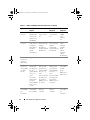
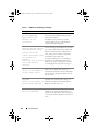
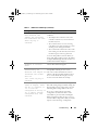
PERC 6 and CERC 6i Controller Features
Table 3-1 compares the hardware configurations for the PERC 6 and CERC 6/i
controllers.
Table 3-1.
PERC 6 and CERC 6/i Controller Comparisons
Specification
PERC 6/E
Adapter
PERC 6/i Adapter
PERC 6/i
Integrated
CERC 6/i
Integrated
RAID Levels
0, 1, 5, 6, 10,
50, 60
0, 1, 5, 6, 10, 50,
60
0, 1, 5, 6, 10, 50,
60
0 and 1
Enclosures
per Port
Up to 3
enclosures
N/A
N/A
N/A
Ports
2 x4 external
wide port
2 x4 internal
wide port
2 x4 internal
wide port
1 x4
internal
wide port
Processor
LSI adapter
LSI adapter SAS
SAS RAID-on- RAID-on-Chip,
Chip, 8-port
8-port with 1078
with 1078
LSI adapter SAS
RAID-on-Chip,
8-port with 1078
LSI adapter
SAS RAIDon-Chip,
8-port with
1078
Battery
Backup Unit
Yes,
Transportable
Yes
No
Yesa
About PERC 6 and CERC 6i Controllers
21
Dell_PERC6.1_UG.book Page 22 Wednesday, April 15, 2009 4:18 PM
Table 3-1. PERC 6 and CERC 6/i Controller Comparisons (continued)
Specification
PERC 6/E
Adapter
PERC 6/i Adapter
PERC 6/i
Integrated
CERC 6/i
Integrated
Cache
Memory
256-MB
DDRII cache
memory size
256-MB DDRII
cache memory
size
256-MB DDRII
cache memory
size
128-MB
DDRII
cache
memory
size
Optional 512MB DIMM
Cache
Function
Write-Back,
Write-Throug
h, Adaptive
Read Ahead,
No-Read
Ahead,
Read Ahead
Write-Back,
Write-Through,
Adaptive
Read Ahead,
No-Read Ahead,
Read Ahead
Write-Back,
Write-Through,
Adaptive
Read Ahead,
No-Read Ahead,
Read Ahead
Write-Back,
WriteThrough,
Adaptive
Read
Ahead,
No-Read
Ahead,
Read Ahead
Maximum
Number of
Spans per
Disk Group
Up to 8 arrays
Up to 8 arrays
Up to 8 arrays
N/A
Maximum
Number of
Virtual Disks
per Disk
Group
Up to 16
virtual disks
per disk group
for nonspanned RAID
levels: 0, 1, 5,
and 6.
Up to 16 virtual
disks per disk
group for nonspanned RAID
levels: 0, 1, 5,
and 6.
Up to 16 virtual
disks per disk
group for nonspanned RAID
levels: 0, 1, 5,
and 6.
Up to 16
virtual disks
per disk
group
One virtual disk
per disk group
for spanned
RAID levels: 10,
50, and 60.
One virtual disk
per disk group
for spanned
RAID levels: 10,
50, and 60.
Up to 64 virtual
disks per
controller
Up to 64 virtual
disks per
controller
One virtual
disk per disk
group for
spanned RAID
levels: 10, 50,
and 60.
Multiple
Virtual Disks
per
Controller
22
Up to 64
virtual disks
per controller
About PERC 6 and CERC 6i Controllers
RAID 0=16
RAID 1=16
Up to 64
virtual disks
per
controller
Dell_PERC6.1_UG.book Page 23 Wednesday, April 15, 2009 4:18 PM
Table 3-1.
PERC 6 and CERC 6/i Controller Comparisons (continued)
Specification
PERC 6/E
Adapter
PERC 6/i Adapter
PERC 6/i
Integrated
CERC 6/i
Integrated
Support for
x8 PCI
Express host
interface
Yes
Yes
Yes
Yes
Online
Capacity
Expansion
Yes
Yes
Yes
Yes
Dedicated
and Global
Hot Spares
Yes
Yes
Yes
Yes
Hot Swap
Devices
Supported
Yes
Yes
Yes
Yes
Non-Disk
Devices
Supported
No
No
No
No
Enclosure
Hot-Addb
Yes
N/A
N/A
N/A
Mixed
Capacity
Physical
Disks
Supported
Yes
Yes
Yes
Yes
Hardware
Yes
Exclusive-OR
(XOR)
Assistance
Yes
Yes
Yes
About PERC 6 and CERC 6i Controllers
23
Dell_PERC6.1_UG.book Page 24 Wednesday, April 15, 2009 4:18 PM
Table 3-1. PERC 6 and CERC 6/i Controller Comparisons (continued)
Specification
PERC 6/E
Adapter
PERC 6/i Adapter
PERC 6/i
Integrated
CERC 6/i
Integrated
Revertible
Hot Spares
Supported
Yes
Yes
Yes
N/A
Redundant
Path Support
Yes
N/A
N/A
N/A
a
b
The PERC 6/i adapter supports a battery backup unit (BBU) on selected systems only. For
additional information, see the documentation that shipped with the system.
Using the enclosure Hot-Add feature you can hot plug enclosures to the PERC 6/E adapter
without rebooting the system.
NOTE: The maximum array size is limited by the maximum number of drives per
disk group (32), the maximum number of spans per disk group (8), and the size of the
physical drives.
NOTE: The number of physical disks on a controller is limited by the number of
slots in the backplane on which the card is attached.
Using the SMART Feature
The Self-Monitoring Analysis and Reporting Technology (SMART) feature
monitors the internal performance of all motors, heads, and physical disk
electronics to detect predictable physical disk failures. The SMART feature
helps monitor physical disk performance and reliability.
SMART-compliant physical disks have attributes for which data (values) can
be monitored to identify changes in values and determine whether the values
are within threshold limits. Many mechanical and electrical failures display
some degradation in performance before failure.
24
About PERC 6 and CERC 6i Controllers
Dell_PERC6.1_UG.book Page 25 Wednesday, April 15, 2009 4:18 PM
A SMART failure is also referred to as a predicted failure. There are numerous
factors that relate to predicted physical disk failures, such as a bearing failure,
a broken read/write head, and changes in spin-up rate. In addition, there are
factors related to read/write surface failure, such as seek error rate
and excessive bad sectors. For information on physical disk status, see "Disk
Roaming" on page 27.
NOTE: For detailed information on Small Computer System Interface (SCSI)
interface specifications, see www.t10.org and for detailed information on for Serial
Attached ATA (SATA) interface specifications, see www.t13.org.
Initializing Virtual Disks
You can initialize the virtual disks in four ways as described in the following
sections.
Background Initialization
Background Initialization (BGI) is an automated process that writes the
parity or mirror data on newly created virtual disks. BGI assumes that the data
is correct on all new drives. BGI does not run on RAID 0 virtual disks.
NOTE: You cannot permanently disable BGI. If you cancel BGI, it automatically
restarts within five minutes. For information on stopping BGI, see "Stopping
Background Initialization" on page 107.
The BGI rate is controlled by the Open Manage storage management
software. After you have changed the BGI rate in Open Manage storage
management software, the change does not take effect until the next BGI
is run.
NOTE: Unlike full or fast initialization of virtual disks, background initialization does
not clear data from the physical disks.
Consistency Check (CC) and BGI perform similar functions in that they
both correct parity errors. However, Consistency Check reports data
inconsistencies through an event notification, but BGI does not (BGI
assumes the data is correct, as it is run only on a newly created disk). You can
start Consistency Check manually, but not Background Initialization.
About PERC 6 and CERC 6i Controllers
25
Dell_PERC6.1_UG.book Page 26 Wednesday, April 15, 2009 4:18 PM
Full Inititialization of Virtual Disks
Performing a full initialization on a virtual disk overwrites all blocks and
destroys any data that previously existed on the virtual disk. A full
initialization eliminates the need for that virtual disk to undergo a
background initialization and can be performed directly after the creation of
a virtual disk.
During full initialization, the host is not be able to access the virtual disk.
You can start a full initialization on a virtual disk by using the Slow Initialize
option in the Dell OpenManage Storage Management application. To use the
BIOS Configuration Utility to perform a full initialization, see "Initializing
Virtual Disks" on page 88.
NOTE: If the system is rebooted during a full initialization, the operation aborts and
a BGI begins on the virtual disk.
Fast Inititialization of Virtual Disks
A fast initialization on a virtual disk overwrites the first and last 8 MB of the
virtual disk, clearing any boot records or partition information. This operation
takes only 2-3 seconds to complete and is recommended when recreating
virtual disks. To perform a fast initialization using the BIOS Configuration
Utility, see "Initializing Virtual Disks" on page 88.
Consistency Checks
Consistency Check is a background operation that verifies and corrects the
mirror or parity data for fault tolerant virtual disks. It is recommended that
you periodically run a consistency check on virtual disks.
You can manually start a consistency check using the BIOS Configuration
Utility or a Open Manage storage management application. To start a
consistency check using the BIOS Configuration Utility, see "Checking Data
Consistency" on page 88. Consistency checks can be scheduled to run on
virtual disks using a Open Manage storage management application.
26
About PERC 6 and CERC 6i Controllers
Dell_PERC6.1_UG.book Page 27 Wednesday, April 15, 2009 4:18 PM
By default, consistency check automatically corrects mirror or parity
inconsistencies. However, you can enable the Abort Consistency Check on
Error feature on the controller using Dell™ OpenManage™ Storage
Management. With the Abort Consistency Check on Error setting enabled,
consistency check notifies if any inconsistency is found and aborts instead of
automatically correcting the error.
Disk Roaming
The PERC 6 and CERC 6/i adapters support moving physical disks from
one cable connection or backplane slot to another on the same controller.
The controller automatically recognizes the relocated physical disks and
logically places them in the proper virtual disks that are part of the disk group.
You can perform disk roaming only when the system is turned off.
CAUTION: Do not attempt disk roaming during RAID level migration (RLM) or
capacity expansion (CE). This causes loss of the virtual disk.
Perform the following steps to use disk roaming:
1 Turn off the power to the system, physical disks, enclosures, and system
components, and then disconnect the power cords from the system.
2 Move the physical disks to different positions on the backplane or the
enclosure.
3 Perform a safety check. Make sure the physical disks are inserted properly.
4 Turn on the system.
The controller detects the RAID configuration from the configuration
data on the physical disks.
Disk Migration
The PERC 6 and CERC 6/i controllers support migration of virtual disks from
one controller to another without taking the target controller offline. However,
the source controller must be offline prior to performing the disk migration.
The controller can import RAID virtual disks in optimal, degraded, or partially
degraded states. You cannot import a virtual disk that is in an offline state.
NOTE: The PERC 6 controllers are not backward compatible with previous Small
Computer System Interface (SCSI), PowerEdge Expandable RAID Controller (PERC),
and Redundant Array of Independent Disks (RAID) controllers.
About PERC 6 and CERC 6i Controllers
27
Dell_PERC6.1_UG.book Page 28 Wednesday, April 15, 2009 4:18 PM
When a controller detects a physical disk with a pre-existing configuration, it
flags the physical disk as foreign, and it generates an alert indicating that a
foreign disk was detected.
CAUTION: Do not attempt disk roaming during RLM or CE. This causes loss of the
virtual disk.
Perform the following steps to use disk migration.
1 Turn off the system that contains the source controller.
2 Move the appropriate physical disks from the source controller to the
target controller.
The system with the target controller can be running while inserting the
physical disks.
The controller flags the inserted disks as foreign disks.
3 Use the Open Manage storage management application to import the
detected foreign configuration.
NOTE: Ensure that all physical disks that are part of the virtual disk are migrated.
NOTE: You can also use the controller BIOS configuration utility to migrate disks.
Compatibility With Virtual Disks Created on PERC 5 Controllers
Virtual disks that were created on the PERC 5 family of controllers can be
migrated to the PERC 6 and CERC 6i controllers without risking data or
configuration loss. Migrating virtual disks from PERC 6 and CERC 6i controllers
to PERC 5 is not supported.
NOTE: For more information about compatibility, contact your Dell Technical
Support Representative.
Virtual disks that were created on the CERC 6/i controller or the PERC 5
family of controllers can be migrated to PERC 6.
28
About PERC 6 and CERC 6i Controllers
Dell_PERC6.1_UG.book Page 29 Wednesday, April 15, 2009 4:18 PM
Compatibility With Virtual Disks Created on SAS 6/iR Controllers
The migration of virtual disks created on the SAS 6/iR family of controllers
can be migrated to PERC 6 and CERC 6i. However, only virtual disks with
boot volumes of the following Linux operating systems successfully boot after
migration:
•
Red Hat Enterprise Linux 4 Update 5
•
Red Hat Enterprise Linux 5
•
SUSE Linux Enterprise Server 10 (64-bit)
NOTE: The migration of virtual disks with Microsoft Windows operating systems is
not supported.
NOTICE: Before migrating virtual disks, back up your data and ensure that the
firmware of both controllers is the latest revision. Also ensure that you use the
SAS 6 firmware version 00.25.41.00.06.22.01.00 or later version.
Migrating Virtual Disks from SAS 6/iR to PERC 6 and CERC 6i
NOTE: The supported operating systems listed above contain a driver for the
PERC 6 and CERC 6i controller family. No additional drivers are needed during the
migration process.
1 If virtual disks with one of the supported Linux operating systems listed
above are being migrated, open a command prompt and type the following
commands:
modprobe megaraid_sas
mkinitrd -f --preload megaraid_sas /boot/initrd-`uname
-r`.img `uname -r`
2 Turn off the system.
3 Move the appropriate physical disks from the SAS 6/iR controller to the
PERC 6 and CERC 6i. If you are replacing your SAS 6/iR controller with a
PERC 6, see the Hardware Owner’s Manual that came with your system.
CAUTION: After you have imported the foreign configuration on the PERC 6 or
CERC 6i storage controllers, you cannot migrate the storage disks back to the SAS
6/iR controller as it may result in the loss of data.
About PERC 6 and CERC 6i Controllers
29
Dell_PERC6.1_UG.book Page 30 Wednesday, April 15, 2009 4:18 PM
4 Boot the system and import the foreign configuration that is detected.
You can do this in two ways as described below:
•
Press <F> to automatically import the foreign configuration
•
Enter the BIOS Configuration Utility and navigate to the Foreign
Configuration View
NOTE: For more information on BIOS Configuration Utility, see "Entering the
BIOS Configuration Utility" on page 79.
NOTE: For more information on Foreign Configuration View, see "Foreign
Configuration View" on page 103
5 If the migrated virtual disk is the boot volume, ensure that the virtual disk
is selected as the bootable volume for the target PERC 6 and CERC 6i
controller. See "Controller Management Actions" on page 103.
6 Exit the BIOS Configuration Utility and reboot the system.
7 Ensure that all the latest drivers available on the Dell support website at
support.dell.com for PERC 6 or CERC 6/i controller are installed. For
more information, see "Installing the Drivers" on page 63.
NOTE: For more information about compatibility, contact your Dell Technical
Support Representative.
Battery Management
NOTE: Battery management is only applicable to PERC 6 family of controllers.
The Transportable Battery Backup Unit (TBBU) is a cache memory module
with an integrated battery pack that enables you to transport the cache
module with the battery into a new controller. The TBBU protects the
integrity of the cached data on the PERC 6/E adapter by providing backup
power during a power outage.
The Battery Backup Unit (BBU) is a battery pack that protects the integrity of
the cached data on the PERC 6/i adapter and PERC 6/i Integrated controllers
by providing backup power during a power outage.
The battery may provide up to 72 hours for a 256-MB controller cache
memory backup power and up to 48 hours for a 512-MB cache when new.
30
About PERC 6 and CERC 6i Controllers
Dell_PERC6.1_UG.book Page 31 Wednesday, April 15, 2009 4:18 PM
Battery Warranty Information
The BBU offers an inexpensive way to protect the data in cache memory.
The lithium-ion battery provides a way to store more power in a smaller form
factor than previous batteries.
The BBU shelf life has been preset to last six months from the time of
shipment without power. To prolong battery life:
•
Deploy the BBU within six months of ship date.
•
Do not store or operate the BBU above 60°C.
•
Disconnect the BBU if the system is going to be turned off (power
disconnected) for longer than one week.
Your PERC 6 battery may provide up to 24 hours of controller cache memory
backup power when new. Under the 1-year limited warranty, we warrant that
the battery will provide at least 24 hours of backup coverage during the 1-year
limited warranty period.
Battery Learn Cycle
Learn cycle is a battery calibration operation performed by the controller
periodically to determine the condition of the battery. This operation cannot
be disabled.
You can start battery learn cycles manually or automatically. In addition, you
can enable or disable automatic learn cycles in the software utility. If you
enable automatic learn cycles, you can delay the start of the learn cycles for
up to 168 hours (7 days). If you disable automatic learn cycles, you can start
the learn cycles manually, and you can choose to receive a reminder to start
a manual learn cycle.
You can put the learn cycle in Warning Only mode. In the Warning mode,
a warning event is generated to prompt you to start the learn cycle manually
when it is time to perform the learn cycle operation. You can select the
schedule for initiating the learn cycle. When in Warning mode, the controller
continues to prompt you to start the learn cycle every seven days until it is
performed.
NOTE: Virtual disks automatically switch to Write-Through mode when the battery
charge is low because of a learn cycle.
About PERC 6 and CERC 6i Controllers
31
Dell_PERC6.1_UG.book Page 32 Wednesday, April 15, 2009 4:18 PM
Learn Cycle Completion Time Frame
The time frame for completion of a learn cycle is a function of the battery
charge capacity and the discharge/charge currents used. For PERC 6, the
expected time frame for completion of a learn cycle is approximately seven
hours and consists of the following parts:
•
Learn cycle discharge cycle: approximately three hours
•
Learn cycle charge cycle: approximately four hours
Learn cycles shorten as the battery capacity deteriorates over time.
NOTE: For additional information, see the OpenManage storage management
application.
During the discharge phase of a learn cycle, the PERC 6 battery charger is
disabled and remains disabled until the battery is discharged. After the
battery is discharged, the charger is re-enabled.
Virtual Disk Write Cache Policies
The write cache policy of a virtual disk determines how the controller handles
writes to that virtual disk. Write-Back and Write-Through are the two write
cache policies and can be set on a virtual disk basis.
Write-Back and Write-Through
In Write-Through caching, the controller sends a data transfer completion signal to
the host system when the disk subsystem has received all the data in a transaction.
In Write-Back caching, the controller sends a data transfer completion signal to
the host when the controller cache has received all the data in a transaction. The
controller then writes the cached data to the storage device in the background.
The risk of using Write-Back cache is that the cached data can be lost if there
is a power failure before it is written to the storage device. This risk is
mitigated by using a BBU on selected PERC 6 controllers. For information on
which controllers support a BBU, see Table 3-1.
Write-Back caching has a performance advantage over Write-Through
caching.
NOTE: The default cache setting for virtual disks is Write-Back caching.
NOTE: Certain data patterns and configurations perform better with a
Write-Through cache policy.
32
About PERC 6 and CERC 6i Controllers
Dell_PERC6.1_UG.book Page 33 Wednesday, April 15, 2009 4:18 PM
Conditions Under Which Write-Back is Employed
Write-Back caching is used under all conditions in which the battery is
present and in good condition.
Conditions Under Which Write-Through is Employed
Write-Through caching is used under all conditions in which the battery is
missing or in a low-charge state. Low-charge state is when the battery is not
capable of maintaining data for at least 24 hours in the case of a power loss.
Conditions Under Which Forced Write-Back With No Battery is
Employed
Write-Back mode is available when the user selects Force WB with no
battery. When Forced Write-Back mode is selected, the virtual disk is in
Write-Back mode even if the battery is not present.
CAUTION: It is recommended that you use a power backup system when forcing
Write-Back to ensure that there is no loss of data if the system suddenly loses
power.
Virtual Disk Read Policies
The read policy of a virtual disk determines how the controller handles reads
to that virtual disk. Some read policies are:
•
Always Read Ahead - Read-Ahead capability allows the controller to read
sequentially ahead of requested data and to store the additional data in
cache memory, anticipating that the data is required soon. This speeds up
reads for sequential data, but there is little improvement when accessing
random data.
•
No Read Ahead - Disables the Read-Ahead capability.
•
Adaptive Read Ahead - When selected, the controller begins using ReadAhead if the two most recent disk accesses occurred in sequential sectors.
If the read requests are random, the controller reverts to No read ahead.
About PERC 6 and CERC 6i Controllers
33
Dell_PERC6.1_UG.book Page 34 Wednesday, April 15, 2009 4:18 PM
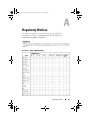
Reconfiguring Virtual Disks
There are two different methods to reconfigure RAID virtual disks — RAID Level
Migration and Online Capacity Expansion. RAID Level Migrations (RLM)
involve the conversion of a virtual disk to a different RAID level and Online
Capacity Expansions (OCE) refer to increasing the capacity of a virtual disk by
adding drives and/or migrating to a different RAID level. When a RLM/OCE
operation is complete and reboot is not necessary. For a list of possible RAID level
migrations and whether or not a capacity expansion is possible in that scenario,
see Table 3-2.
The source RAID level column indicates the virtual disk level before the
RAID level migration and the target RAID level column indicates the RAID
level after the operation is complete.
NOTE: If you configure 64 virtual disks on a controller, you cannot perform a RAID
level migration or capacity expansion on any of the virtual disks.
NOTE: The controller changes the write cache policy of all virtual disks undergoing
a RLM/OCE to Write-Through until the RLM/OCE is complete.
Table 3-2.
RAID Level Migration
Source Target
RAID
RAID
Level
Level
Required
Number of
Physical
Disks
(Beginning)
Number of Capacity Description
Physical Expansion
Disks
Possible
(End)
RAID 0 RAID 1 1
2
RAID 0 RAID 5 1 or more
3 or more Yes
At least one drive needs to be
added for distributed parity
data.
RAID 0 RAID 6 1 or more
4 or more Yes
At least two drives need to be
added for dual distributed
parity data.
RAID 1 RAID 0 2
2
Removes redundancy while
doubling capacity.
34
No
Yes
About PERC 6 and CERC 6i Controllers
Converting non-redundant
virtual disk into a mirrored
virtual disk by adding one
drive.
Dell_PERC6.1_UG.book Page 35 Wednesday, April 15, 2009 4:18 PM
Table 3-2.
RAID Level Migration (continued)
Source Target
RAID
RAID
Level
Level
Required
Number of
Physical
Disks
(Beginning)
Number of Capacity Description
Physical Expansion
Possible
Disks
(End)
RAID 1 RAID 5 2
3 or more Yes
Removes redundancy while
doubling capacity.
RAID 1 RAID 6 2
4 or more Yes
Two drives are required to be
added for distributed parity
data.
RAID 5 RAID 0 3 or more
2 or more Yes
Converting to a non-redundant
virtual disk and reclaiming disk
space used for distributed
parity data.
RAID 5 RAID 6 3 or more
4 or more Yes
At least one drive needs to be
added for dual distributed
parity data.
RAID 6 RAID 0 4 or more
2 or more Yes
RAID 6 RAID 5 4 or more
3 or more Yes
Converting to a non-redundant
virtual disk and reclaiming disk
space used for distributed
parity data.
Removing one set of parity
data and reclaiming disk space
used for it.
NOTE: The total number of physical disks in a disk group cannot exceed 32.
NOTE: You cannot perform RAID level migration and expansion on RAID levels 10,
50, and 60.
About PERC 6 and CERC 6i Controllers
35
Dell_PERC6.1_UG.book Page 36 Wednesday, April 15, 2009 4:18 PM
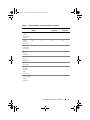
Fault Tolerance Features
Table 3-3 lists the features that provide fault tolerance to prevent data loss in
case of a failed physical disk.
Table 3-3.
Fault Tolerance Features
Specification
PERC
CERC
Support for SMART
Yes
Yes
Support for Patrol Read
Yes
Yes
Redundant path support
Yes
N/A
Physical disk failure detection
Automatic
Automatic
Physical disk rebuild using hot spares
Automatic
Automatic
Parity generation and checking (RAID 5, 50, 6, and Yes
60 only)
N/A
Battery backup of controller cache to protect data Yesa
N/A
Manual learn cycle mode for battery backup
Yes
N/A
Detection of batteries with low charge after
bootup
Yes
N/A
Hot-swap manual replacement of a physical disk
without reboot
Yes
Yes
a
The PERC 6/i adapter supports a BBU on selected systems only. For additional information, see
the documentation that was shipped with the system.
Physical Disk Hot Swapping
Hot swapping is the manual substitution of a replacement unit in a disk
subsystem for a defective one. The manual substitution can be performed while
the subsystem is performing its normal functions.
NOTE: The system backplane or enclosure must support hot swapping in order for
the PERC 6 and CERC 6/i controllers to support hot swapping.
NOTE: Ensure that SAS drives are replaced with SAS drives, and SATA drives are
replaced with SATA drives.
NOTE: While swapping a disk, ensure that the new disk is of equal or greater
capacity than the disk that is being replaced.
36
About PERC 6 and CERC 6i Controllers
Dell_PERC6.1_UG.book Page 37 Wednesday, April 15, 2009 4:18 PM
Failed Physical Disk Detection
The controller automatically detects and rebuilds failed physical disks when
a new drive is placed in the slot where the failed drive resided or when an
applicable hot spare is present. Automatic rebuilds can be performed
transparently with hot spares. If you have configured hot spares, the
controllers automatically try to use them to rebuild failed physical disks.
Redundant Path With Load Balancing Support
The PERC 6/E adapter can detect and use redundant paths to drives
contained in enclosures. This provides the ability to connect two SAS cables
between a controller and an enclosure for path redundancy. The controller is
able to tolerate the failure of a cable or enclosure management module
(EMM) by utilizing the remaining path.
When redundant paths exist, the controller automatically balances I/O load
through both paths to each disk drive. This load balancing feature increases
throughput to each drive and is automatically turned on when redundant
paths are detected. To set up your hardware to support redundant paths, see
"Setting up Redundant Path Support on the PERC 6/E Adapter" on page 56.
NOTE: This support for redundant paths refers to path-redundancy only and not to
controller-redundancy.
Using Replace Member and Revertible Hot Spares
The Replace Member functionality allows a previously commissioned hot spare
to be reverted back to a usable hot spare. When a drive failure occurs within
a virtual disk, an assigned hot spare (dedicated or global) is commissioned and
begins rebuilding until the virtual disk is optimal. After the failed drive is
replaced (in the same slot) and the rebuild to the hot spare is complete, the
controller automatically starts to copy data from the commissioned hot spare to
the newly-inserted drive. After the data is copied, the new drive is part of the
virtual disk and the hot spare is reverted back to being a ready hot spare; this
allows hot spares to remain in specific enclosure slots. While the controller is
reverting the hot spare, the virtual disk remains optimal.
NOTE: The controller automatically reverts a hot spare only if the failed drive is
replaced with a new drive in the same slot. If the new drive is not placed in the
same slot, a manual Replace Member operation can be used to revert a previously
commissioned hot spare.
About PERC 6 and CERC 6i Controllers
37
Dell_PERC6.1_UG.book Page 38 Wednesday, April 15, 2009 4:18 PM
Automatic Replace Member with Predicted Failure
A Replace Member operation can occur when there is a SMART predictive
failure reporting on a drive in a virtual disk. The automatic Replace Member
is initiated when the first SMART error occurs on a physical disk that is part
of a virtual disk. The target drive needs to be a hot spare that qualifies as
a rebuild drive. The physical disk with the SMART error is marked as failed
only after the successful completion of the Replace Member. This avoids
putting the array in degraded status.
If an automatic Replace Member occurs using a source drive that was
originally a hot spare (that was used in a rebuild), and a new drive added for
the Replace Member operation as the target drive, the hot spare reverts to
the hot spare state after a successful Replace Member operation.
NOTE: To enable the automatic Replace Member, use the Dell OpenManage
Storage Management. For more information on automatic Replace Member,
see "Dell OpenManage Storage Management" on page 77.
NOTE: For information on manual Replace Member, see "Replacing an Online
Physical Disk" on page 106.
Patrol Read
The Patrol Read feature is designed as a preventative measure to ensure
physical disk health and data integrity. Patrol Read scans for and resolves
potential problems on configured physical disks. The Open Manage storage
management application can be used to start Patrol Read and change its
behavior.
Patrol Read Feature
The following is an overview of Patrol Read behavior:
1 Patrol Read runs on all disks on the controller that are configured as part
of a virtual disk including hot spares.
2 Patrol Read does not run on unconfigured physical disks. Unconfigured
disks are those that are not part of a virtual disk or are in Ready state.
38
About PERC 6 and CERC 6i Controllers
Dell_PERC6.1_UG.book Page 39 Wednesday, April 15, 2009 4:18 PM
3 Patrol Read adjusts the amount of controller resources dedicated to Patrol
Read operations based on outstanding disk I/O. For example, if the system
is busy processing I/O operation, then Patrol Read uses fewer resources to
allow the I/O to take a higher priority.
4 Patrol Read does not run on any disks that are involved in any of the
following operations:
•
Rebuild
•
Replace Member
•
Full or Background Initializations
•
Consistency Check
•
RAID Level Migration or Online Capacity Expansion
Patrol Read Modes
The following describes each of the modes Patrol Read can be set to:
•
Auto (default)- Patrol Read is set to the Auto mode by default. This
means that it is enabled to run automatically and start every seven days.
You can start and stop Patrol Read as well.
•
Manual - Patrol Read does not run automatically. You must start the
Patrol Read manually when the Manual mode is set.
•
Disabled - Patrol Read is not allowed to start on the controller.
About PERC 6 and CERC 6i Controllers
39
Dell_PERC6.1_UG.book Page 40 Wednesday, April 15, 2009 4:18 PM
40
About PERC 6 and CERC 6i Controllers
Dell_PERC6.1_UG.book Page 41 Wednesday, April 15, 2009 4:18 PM
Installaing and Configuring
Hardware
CAUTION: Only trained service technicians are authorized to remove the system
cover and access any of the components inside the system. Before performing any
procedure, refer to the safety and warranty information that shipped with your
system for complete information about safety precautions, working inside the
computer, and protecting against electrostatic discharge.
CAUTION: Electrostatic discharge can damage sensitive components. Always
use proper antistatic protection when handling components. Touching
components without using a proper ground can damage the equipment.
Installing the PERC 6/E and PERC 6/i Adapters
1 Unpack the PERC 6/E adapter and check for damage.
NOTE: Contact Dell Technical support if the controller is damaged.
2 Turn off the system and attached peripherals, and disconnect the system
from the electrical outlet. For more information on power supplies, refer to
your system’s Hardware Owner’s Manual.
3 Disconnect the system from the network and remove the system cover. For
more information on opening the system, refer to your system’s Hardware
Owner’s Manual.
4 Select an empty PCI Express (PCI-E) slot. Remove the blank filler bracket
on the back of the system aligned with the PCI-E slot you have selected.
5 Align the PERC 6/E adapter to the PCI-E slot you have selected.
CAUTION: Never apply pressure to the memory module while inserting the
controller into the PCI-E slot. Applying pressure could break the module
6 Insert the controller gently, but firmly, until the controller is firmly seated
in the PCI-E slot. For more information on PERC 6 adapter,
see Figure 4-1. For more information on PERC 6/i adapter, see Figure 4-2.
NOTE: For a list of compatible controllers, see the documentation that
shipped with the system.
Installing and Configuring Hardware
41
Dell_PERC6.1_UG.book Page 42 Wednesday, April 15, 2009 4:18 PM
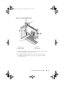
Figure 4-1.
Installing a PERC 6/E Adapter
1
4
2
3
42
1
bracket screw
3
PCI-e slot
2
PERC 6/i adapter
4
filler brackets
Installing and Configuring Hardware
Dell_PERC6.1_UG.book Page 43 Wednesday, April 15, 2009 4:18 PM
Figure 4-2.
Installing a PERC 6/i Adapter
1
4
2
3
1
bracket screw
3
PCI-e slot
2
PERC 6/i adapter
4
filler brackets
7 Tighten the bracket screw, if any, or use the system’s retention clips to
secure the controller to the system’s chassis.
8 For PERC 6/E adapter, replace the cover of the system. For more
information on closing the system, refer to your system’s Hardware
Owner’s Manual.
Installing and Configuring Hardware
43
Dell_PERC6.1_UG.book Page 44 Wednesday, April 15, 2009 4:18 PM
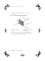
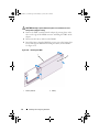
9 Connect the cable from the external enclosure to the controller.
See Figure 4-3.
Figure 4-3. Connecting the Cable From the External Enclosure
1
2
3
1
connector on the controller
3
cable from the external enclosure
2
system
4
memory module
10 For PERC 6/i adapter, connect the cables from the backplane of the
system to the controller. The primary SAS connector is white and the
secondary SAS connector is black. See Figure 4-4.
44
Installing and Configuring Hardware
Dell_PERC6.1_UG.book Page 45 Wednesday, April 15, 2009 4:18 PM
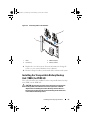
Figure 4-4.
Connecting Cables to the Controller
1
3
2
1
cable
3
PERC 6/i adapter
2
connectory
4
memory module
11 Replace the cover of the system. For more information on closing the
system, see your system’s Hardware Owner’s Manual.
12 Reconnect the power cables(s) and network cables, and turn on the system.
Installing the Transportable Battery Backup
Unit (TBBU) for PERC 6/E
This section describes the installation of the transportable battery backup
unit (TBBU) on the PERC 6/E.
CAUTION: The following procedure must be performed at an Electrostatic
Discharge (ESD)-safe workstation to meet the requirements of EIA-625 "Requirements For Handling Electrostatic Discharge Sensitive Devices."
The following procedure must be performed following the IPC-A-610 latest
revision ESD recommended practices.
Installing and Configuring Hardware
45
Dell_PERC6.1_UG.book Page 46 Wednesday, April 15, 2009 4:18 PM
1 Unpack the TBBU and follow all antistatic procedures.
NOTICE: When transporting a sensitive component, first place it in an antistatic
container or packaging.
NOTE: Handle all sensitive components in a static-safe area. If possible, use
antistatic floor pads and work bench pads.
2 With the DIMM removed from the controller, insert one end of the
battery pack harness (the red, white, yellow, and green wires) into the
connector on the memory module and the other end into the connector on
the battery.
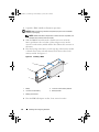
3 Place the top edge of the battery over the top edge of the memory module
so that the arms on the side of the battery fit into their sockets on the
memory module. See Figure 4-5.
Figure 4-5. Installing a TBBU
1
5
4
2
3
1
battery
4
connector on the memory module
2
connector on the battery
5
memory module
3
battery pack harness
4 Place the PERC 6/E adapter on a flat, clean, static–free surface.
46
Installing and Configuring Hardware
Dell_PERC6.1_UG.book Page 47 Wednesday, April 15, 2009 4:18 PM
5 Mount the memory module in the controller memory socket like a
standard DIMM. For more information, see "Installing the DIMM on a
PERC 6/E Adapter" on page 47.
The memory module is mounted flush with the board so that the memory
module is parallel to the board when installed.
6 Press the memory module firmly into the memory socket.
As you press the memory module into the socket, the TBBU clicks into
place, indicating that the controller is firmly seated in the socket, and the
arms on the socket fit into the notches to hold the memory module
securely.
Installing the DIMM on a PERC 6/E Adapter
This section describes how to install the memory module on a PERC 6/E
adapter.
NOTICE: PERC 6 cards support Dell-qualified 512-MB and 256-MB DDRII 667MHz
ECC-registered DIMMs with x16 DRAM components. Installing unsupported
memory causes the system to hang at POST.
1 Remove the memory module in an antistatic environment.
NOTE: When unpacking a static sensitive component from its shipping
carton, do not remove the component from the antistatic packing material
until you are ready to install the component. Before unwrapping the antistatic
package, ensure to discharge static electricity from your body.
NOTE: Handle all sensitive components in a static-safe area. If possible, use
antistatic floor pads and work bench pads.
NOTE: Do not touch the gold leads and do not bend the memory module.
2 Align the memory module so that the keyed edge of the memory
module is placed exactly on top of the physical divider on the memory
socket of the controller to avoid damage to the DIMM.
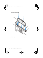
3 Insert the memory module on the memory socket of the controller and
apply a smooth, downward pressure on both ends or on the middle of the
memory module until the retention clips fall into the allotted slots on
either side of the memory module. See Figure 4-6.
Figure 4-6 displays the installation of a memory module on a PERC 6/E
adapter.
Installing and Configuring Hardware
47
Dell_PERC6.1_UG.book Page 48 Wednesday, April 15, 2009 4:18 PM
Figure 4-6. Installing a DIMM
4
3
1
2
48
1
PERC 6/E adapter
3
memory socket
2
retention clip
4
memory module
Installing and Configuring Hardware
Dell_PERC6.1_UG.book Page 49 Wednesday, April 15, 2009 4:18 PM
Transferring a TBBU Between Controllers
The TBBU provides uninterrupted power supply to the memory module for
up to 72 hours (for a 256 MB of controller cache memory) backup power and
up to 48 hours (for a 512 MB cache) if power supply is unexpectedly
interrupted while cached data is still present. If the controller fails as a result
of a power failure, you can move the TBBU to a new controller and recover
the data. The controller that replaces the failed controller must be devoid of
any prior configuration.
Perform the following steps to replace a failed controller with data in the
TBBU:
1 Perform a controlled shutdown on the system in which the PERC 6/E is
installed, as well as any attached storage enclosures.
2 Remove the controller that has the TBBU currently installed from the
system.
3 Remove the TBBU from the controller.
4 Insert the TBBU into the new controller.
See "Replace the cover of the system. For more information on closing the
system, see your system’s Hardware Owner’s Manual." on page 45.
5 Insert the new controller into the system.
See the relevant sections on installing controllers under "Installing the
PERC 6/E and PERC 6/i Adapters" on page 41.
6 Turn on the system.
The controller flushes the cache data to the virtual disks.
Installing and Configuring Hardware
49
Dell_PERC6.1_UG.book Page 50 Wednesday, April 15, 2009 4:18 PM
Removing the PERC 6/E and PERC 6/i Adapters
NOTE: In the event that the SAS cable is accidentally pulled when the system is
operational, reconnect the cable and see the online help of your Open Manage
storage management application for the required recovery steps.
NOTE: Some PERC 6/i adapters installed on a Dell workstation or Dell SC systems
do not have a BBU.
1 Perform a controlled shutdown on the system in which the PERC 6/E is
installed, as well as any attached storage enclosures.
2 Disconnect the system from the electrical outlet and remove the system
cover.
CAUTION: Running a system without the system cover installed may cause
damage due to improper cooling.
NOTE: For more information on removing and reinstalling the system cover,
refer to the Hardware Owner’s Manual that shipped with the system.
3 For removing a PERC 6/E adapter, locate the PERC 6/E in the system and
disconnect the external cables from the PERC 6/E.
4 Remove any retention mechanism such as a bracket screw that may be
holding the PERC 6/E in the system and gently lift the controller from the
system’s PCI-E slot. See Figure 4-7.
50
Installing and Configuring Hardware
Dell_PERC6.1_UG.book Page 51 Wednesday, April 15, 2009 4:18 PM
Figure 4-7. Removing the PERC 6/E Adapter
4
1
2
3
1
battery
3
PERC 6/E adapter
2
memory module
4
bracket screw
NOTE: For more information on removing peripherals installed in the system’s
PCI-E slots, see the Hardware Owner’s Manual that shipped with the system.
5 For removing a PERC 6/i adapter, determine whether the dirty cache LED
on the controller is illuminated.
•
If the LED is illuminated, replace the system cover, reconnect the
system to power, turn on the system, and repeat step 1 and step 2. See
Figure 4-8.
NOTE: The location of the PERC 6/i varies from system to system. For
information on PERC 6/i card location, see the Hardware Owner’s Manual that
shipped with the system.
•
If the LED is not illuminated, continue with the next step.
Installing and Configuring Hardware
51
Dell_PERC6.1_UG.book Page 52 Wednesday, April 15, 2009 4:18 PM
Figure 4-8. Removing the PERC 6/i Adapter
1
2
3
1
bracket screw
2
PERC 6/i
3
Dirty Cache LED location
6 Disconnect the data cables and battery cable from the PERC 6/i. Remove
any retention mechanism, such as a bracket screw, that might be holding
the PERC 6/i in the system, and gently lift the controller from the system’s
PCI-E slot.
NOTE: For more information on removing the PERC 6/i adapter from the system, see
your system’s Hardware Owner’s Manual.
52
Installing and Configuring Hardware
Dell_PERC6.1_UG.book Page 53 Wednesday, April 15, 2009 4:18 PM
Removing the DIMM and Battery from a PERC 6/E
Adapter
NOTE: The TBBU on the PERC 6/E adapter consists of a DIMM and battery backup
unit.
This section describes how to remove the TBBU from a PERC 6/E adapter
that is currently installed in a system.
1 Perform a controlled shutdown on the system in which the PERC 6/E
adapter is installed, as well as any attached storage enclosures, and remove
the PERC 6/E adapter from the system by following the instructions
detailed in "Removing the PERC 6/E and PERC 6/i Adapters" on page 50.
2 Visually inspect the controller and determine whether the dirty cache LED
on the DIMM is illuminated. See Figure 4-9. If the LED is illuminated,
reinsert the controller into the system, replace the system cover, reconnect
the system to power, turn the system on and repeat step 1.
Figure 4-9. PERC 6/E Adapter Dirty Cache LED Location
1
2
3
4
1
battery
3
dirty cache LED
2
memory module
4
PERC 6/E adapter
Installing and Configuring Hardware
53
Dell_PERC6.1_UG.book Page 54 Wednesday, April 15, 2009 4:18 PM
CAUTION: Running a system without the system cover installed can cause
damage due to improper cooling.
3 Remove the TBBU assembly from the adapter by pressing down on the
tabs at each edge of the DIMM connector and lifting the TBBU off the
adapter.
4 Disconnect the battery cable from the DIMM.
5 Detach the battery from the DIMM by pressing out on the battery clips
inserted through the DIMM and rotating the battery off the DIMM.
See Figure 4-10.
Figure 4-10. Removing the TBBU
1
1
54
memory module
2
2
Installing and Configuring Hardware
battery
Dell_PERC6.1_UG.book Page 55 Wednesday, April 15, 2009 4:18 PM
Disconnecting the BBU from a PERC 6/i Adapter
or a PERC 6/i Integrated Controller
NOTE: A PERC 6/i adapter installed in a Dell workstation or a Dell SC system does not
have a BBU.
NOTE: Batteries with low charges can be detected and recharged. The battery
must first be charged and the system must be restarted for the battery to be active
again.
This section describes how to disconnect the BBU on a PERC 6/i adapter or a
PERC 6/i Integrated controller while the adapter or controller is installed in a
system.
1 Perform a controlled shutdown on the system in which the PERC 6/i is
installed.
2 Disconnect the system from the electrical outlet and remove the system
cover.
CAUTION: Running a system without the system cover installed can cause damage
due to improper cooling.
NOTE: For more information on removing and replacing the system cover,
refer to the Hardware Owner’s Manual that shipped with the system.
3 Determine whether the dirty cache LED on the controller is illuminated.
•
If the LED is illuminated, replace the system cover, reconnect the
system to power, turn on the system, and repeat step 1 and step 2.
NOTE: The location of the PERC 6/i varies from system to system. For
information on PERC 6/i card location, see the Hardware Owner’s
Manual that shipped with the system.
•
If the LED is not illuminated, continue with the next step.
4 Locate the battery cable connection on the controller and disconnect the
battery.
Installing and Configuring Hardware
55
Dell_PERC6.1_UG.book Page 56 Wednesday, April 15, 2009 4:18 PM
Setting up Redundant Path Support on the
PERC 6/E Adapter
The PERC 6/E adapter can detect and use redundant paths to drives
contained in enclosures. With redundant paths to the same port of a device,
if one path fails, another path can be used to communicate between the
controller and the device. For more information about redundant paths, see
"Redundant Path With Load Balancing Support" on page 37.
To set up a configuration with redundant paths, both ports on a controller
must be cabled to the IN ports of a single enclosure.
To add multiple enclosures, both OUT ports of the first enclosure must be
cabled to the IN ports of the next enclosure.
If the connection between an OUT port on the controller and an IN port on
an enclosure fails, an alternate path exists through the second OUT port on
the controller and the second In port on the enclosure. For more information,
see Figure 4-11, Figure 4-12 and Figure 4-13.
NOTE: The PERC 6/E adapter supports redundant paths when used with Dell
PowerVault MD1000 and Dell PowerVault MD1120 disk storage enclosures.
Figure 4-11 displays Redundant path Storage Configuration with one
enclosure.
Figure 4-11. Redundant Path Support Configuration With One Enclosure
Storage
56
Installing and Configuring Hardware
Storage
Dell_PERC6.1_UG.book Page 57 Wednesday, April 15, 2009 4:18 PM
Figure 4-12 displays Redundant path Storage Configuration with two
enclosures.
Figure 4-12.
Redundant Path Support Configuration With Two Enclosures
Storage
Storage
Storage
Storage
Installing and Configuring Hardware
57
Dell_PERC6.1_UG.book Page 58 Wednesday, April 15, 2009 4:18 PM
Figure 4-13 displays Redundant path Storage Configuration with three
enclosures
Figure 4-13. Redundant Path Support Configuration With Three Enclosures
Storage
Storage
Storage
Storage
Storage
Storage
A single PERC 6/E adapter can support up to three disk storage enclosures in
a redundant path configuration.
NOTE: Ensure that the latest firmware version is installed on your storage
controller. You can download the latest firmware from the Dell Support website at
support.dell.com and flash it to the firmware on the controller. For the latest
firmware installation instructions, see the system documentation located on the
Dell Support website at support.dell.com.
58
Installing and Configuring Hardware
Dell_PERC6.1_UG.book Page 59 Wednesday, April 15, 2009 4:18 PM
Perform the following steps to configure the hardware to utilize
redundantpaths on the PERC 6/E adapter:
1 Set up an enclosure on the PERC 6/E adapter.
2 Connect two SAS cables from the OUT ports on your PERC 6/E adapter
to the IN ports of the external enclosure. See Figure 4-3 to view the
connection of the cables from the external enclosure to the PERC 6/E
adapter.
NOTE: For information on Unified Mode, see the enclosure documentation
that was shipped with the system.
3 To add multiple enclosures, cable both OUT ports of the first enclosure
to both IN ports of the next enclosure.
After you set up the hardware, the controller detects the redundant paths and
automatically utilizes them to balance the I/O load.
Removing and Installing the CERC 6/i Modular
Storage Controller Card (Service-Only Procedure)
The Modular Storage Controller Card is located below the hard drive bays of
the Dell Modular
Blade system. To remove the Modular Storage Controller Card:
1 Remove the Dell Modular Blade system from the Modular blade system
chassis. For more information on removing the blade system from the
Modular Blade system chassis, see your system’s Hardware Owner’s
Manual or the User’s Guide.
2 Remove the system cover of the Modular blade system. For more
information on opening the top cover of the Modular blade system, see
your system’s Hardware Owner’s Manual or the User’s Guide.
3 Remove the system board and place it on a stable, flat work surface.
For more information on removing the system board, see your system’s
Hardware Owner’s Manual or the User’s Guide.
Installing and Configuring Hardware
59
Dell_PERC6.1_UG.book Page 60 Wednesday, April 15, 2009 4:18 PM
4 Open the release lever to disconnect the Modular Storage Controller Card
edge connector from the system board connector as illustrated in
Figure 4-14.
5 Lift the Modular Storage Controller Card straight up from the system
board as illustrated in Figure 4-14.
NOTICE: Do not apply pressure to the internal SAS port connectors as they could
be damaged.
NOTICE: Electrostatic discharge can damage sensitive components. Always use
proper antistatic protection when handling components. Touching components
without using a proper ground can damage the equipment.
Figure 4-14. Removing and Installing the Storage Controller Card
2
1
1
60
storage controller card
2
Installing and Configuring Hardware
release lever
Dell_PERC6.1_UG.book Page 61 Wednesday, April 15, 2009 4:18 PM
Installing the Modular Storage Controller Card
To install your new CERC 6/i Modular Storage Controller:
1 Unpack the new CERC 6/i Modular Storage Controller Card and check for
damage.
NOTE: If the card is damaged, contact Dell.
2 Place the Modular Storage Controller Card onto the System Board.
Place by aligning the Modular Storage Controller Card such that the tabs
on the metal System Board tray fit through the notches in the edges of the
Modular Storage Controller Card.
3 Slide the Modular Storage Controller Card towards the connector on the
System Board until the Modular Storage Controller Card’s edge connector
clicks into place.
4 Reinstall the System Board. For more information on reinstalling the
System Board, see your system’s Hardware Owner’s Manual or the User’s
Guide.
5 Close the top cover of the Modular blade system. For more information on
closing the top cover of the Modular blade system, see your system’s
Hardware Owner’s Manual or the User’s Guide.
6 Reinstall the Modular blade system in the Modular blade system chassis.
For more information on reinstalling the Modular blade system into the
Modular blade system chassis, see your system’s Hardware Owner’s
Manual or the User’s Guide.
NOTE: The CERC 6/i Modular does not provide support for a battery backup unit.
NOTE: For the latest list of firmware and driver installation instructions, see the
system documentation located at the Dell Support website at support.dell.com.
Installing and Configuring Hardware
61
Dell_PERC6.1_UG.book Page 62 Wednesday, April 15, 2009 4:18 PM
62
Installing and Configuring Hardware
Dell_PERC6.1_UG.book Page 63 Wednesday, April 15, 2009 4:18 PM
Installing the Drivers
The Dell™ PowerEdge™ Expandable RAID Controller (PERC) 6 and Dell
Cost-Effective RAID Controller (CERC) 6/i family of controllers require
software drivers to operate with the supported operating systems.
This chapter contains the procedures for installing the drivers for the following
operating systems.
•
Citrix® XenServer Dell Edition
•
Microsoft® Windows® Server® 2003
•
Microsoft Windows XP
•
Microsoft Windows Vista™
•
Microsoft Windows Server 2008 (including Hyper-V virtualization)
•
Novell® NetWare® 6.5
•
Red Hat® Enterprise Linux™ Version 4 Update 5 and Red Hat Enterprise
Linux Version 5
•
Solaris™10 Update 5 (64-bit)
•
SUSE® Linux Enterprise Server Version 9 SP4 (64-bit) and SUSE Linux
Enterprise Server Version 10 (64-bit)
•
VMware® ESX 3.5 and 3.5i
NOTE: For more information on Citrix XenServer and VMware ESX drivers, refer to
the Citrix XenServer and VMware ESX documentation respectively.
NOTE: To check operating system compatibility, refer to the Dell Support website at
support.dell.com.
The two methods for installing a driver that are discussed in this chapter are:
•
During operating system installation—Use this method if you are
performing a new installation of the operating system and want to include
the drivers.
•
Updating existing drivers—Use this method if the operating system and
PERC 6 and CERC 6i family of controllers are already installed and you
want to update to the latest drivers.
Installing the Drivers
63
Dell_PERC6.1_UG.book Page 64 Wednesday, April 15, 2009 4:18 PM
Installing Windows Driver
This section documents the procedures used to install the Windows driver.
Creating the Driver Media
Perform the following steps to create the driver media:
1 Browse to the download section for the system from the Dell Support
website at support.dell.com.
2 Locate and download the latest PERC 6 controller driver to the system.
3 Follow the instructions on the Dell Support website for extracting the
driver to the media.
Pre-Installation Requirements
Before you install the operating system:
•
Read the Microsoft Getting Started document that ships with your
operating system.
•
Ensure that your system has the latest BIOS, firmware, and driver updates.
If required, download the latest BIOS, firmware, and driver updates from
the Dell Support website at support.dell.com.
•
Create a device driver media (diskette, USB drive, CD, or DVD).
Creating the Device Driver Media
Use one of the following two methods to create the device driver media.
Downloading Drivers From the Dell Systems Service and Diagnostic Tools Media
1 Insert the Dell Systems Service and Diagnostics Tools media into a system.
The Welcome to Dell Service and Diagnostic Utilities screen is displayed.
2 Select your system model and operating system (Microsoft Windows
Server 2008).
3 Click Continue.
64
Installing the Drivers
Dell_PERC6.1_UG.book Page 65 Wednesday, April 15, 2009 4:18 PM
4 From the list of drivers displayed, select the driver that you require. Select
the self-extracting zip file and click Run. Copy the driver to a diskette
drive, CD, DVD, or USB drive. Repeat this step for all the drivers that you
require.
5 During the operating system installation described in "Installing the Driver
During a Windows Server 2003 or Windows XP Operating System
Installation" on page 66, "Installing the Driver During a Windows Server
2008 or Windows Vista Installation" on page 66 and "Installing a Windows
Server 2003, Windows Server 2008, Windows Vista, or Windows XP Driver
for a New RAID Controller" on page 67, use the media that you created
with the Load Driver option to load mass storage drivers.
Downloading Drivers From the Dell Support Site
1 Go to support.dell.com.
2 Click Drivers and Downloads.
3 Enter the service tag of your system in the Choose by Service Tag field or
select your system’s model.
4 Select the System Type, Operating System, Driver Language, and
Category from the drop-down list.
5 The drivers that are applicable to your selection are displayed. From the
available list, download the drivers that you require to a diskette drive,
USB drive, CD, or DVD.
6 During the operating system installation described in "Installing the Driver
During a Windows Server 2003 or Windows XP Operating System
Installation" on page 66 and "Installing the Driver During a Windows
Server 2003 or Windows XP Operating System Installation" on page 66,
use the media that you created with the Load Driver option to load mass
storage drivers.
Installing the Drivers
65
Dell_PERC6.1_UG.book Page 66 Wednesday, April 15, 2009 4:18 PM
Installing the Driver During a Windows Server 2003 or Windows XP
Operating System Installation
Perform the following steps to install the driver during operating system
installation.
1 Boot the system using the Microsoft Windows XP/Microsoft Windows
Server 2003 media.
2 When the message Press F6 if you need to install a third party SCSI or
RAID driver appears, press the <F6> key immediately.
Within a few minutes, a screen appears that asks for additional controllers
in the system.
3 Press the <S> key.
The system prompts for the driver media to be inserted.
NOTE: The driver can be provided using a properly formatted USB key.
For additional details on the driver, go the Dell Support website at
support.dell.com.
4 Insert the driver media in the media drive and press <Enter>.
A list of PERC 6 and CERC 6i controllers appears.
5 Select the right driver for the installed controller and press <Enter> to
load the driver.
NOTE: For Windows Server 2003, a message may appear that states that the
driver that you provided is older or newer than the existing Windows driver.
Press <S> to use the driver that is on the media.
6 Press <Enter> again to continue the installation process as usual.
Installing the Driver During a Windows Server 2008 or Windows Vista
Installation
Perform the following steps to install the driver during operating system
installation.
1 Boot the system using the Microsoft Windows Vista/Microsoft Windows
Server 2008 media.
2 Follow on-screen instructions until you reach Where do you want to install
Vista/2008 and select Load driver...
66
Installing the Drivers
Dell_PERC6.1_UG.book Page 67 Wednesday, April 15, 2009 4:18 PM
3 The system prompts for the media to be inserted. Insert the installation
media and browse to the proper location.
4 Select the appropriate PERC 6 controller from the list, click Next and
continue installation.
NOTE: Windows Server 2008 and Windows Vista operating systems include
native support for the PERC 6 and CERC 6i RAID controller. The driver is
automatically installed. For driver updates, see the Drivers and Downloads
section on the Dell Support website at support.dell.com.
Installing a Windows Server 2003, Windows Server 2008, Windows Vista,
or Windows XP Driver for a New RAID Controller
NOTE: PERC 5 and PERC 6 use the same driver and do not require separate driver
installations.
Perform the following steps to configure the driver for the RAID controller on
a system that already has Windows installed.
1 Turn off the system.
2 Install the new RAID controller in the system.
For detailed instructions on installing and cabling the RAID controller in
the system, see "Installaing and Configuring Hardware" on page 41.
3 Turn on the system.
The Windows operating system detects the new controller and displays a
message to inform the user.
4 The Found New Hardware Wizard screen pops up and displays the
detected hardware device.
NOTE: Windows 2008 and Vista include a device driver to support the PERC
adapters. The system automatically detects the new controller and installs the
driver. Check the version of the driver installed by Windows and update if
required.
5 Click Next.
6 On the Locate device driver screen, select Search for a suitable driver for
my device and click Next.
7 Make the Driver Files available and browse to the proper location from the
Locate Driver Files screen.
Installing the Drivers
67
Dell_PERC6.1_UG.book Page 68 Wednesday, April 15, 2009 4:18 PM
8 Click Next.
9 The wizard detects and installs the appropriate device drivers for the new
RAID controller.
10 Click Finish to complete the installation.
11 Reboot the system when prompted.
Updating an Existing Windows Server 2003, Windows Server 2008,
Windows XP, or Windows Vista Driver
Perform the following steps to update the Microsoft Windows driver for the
PERC 6 controller already installed on your system.
NOTE: It is important that you close all applications on your system before you
update the driver.
1 Select Start→ Settings→ Control Panel→ System.
The System Properties screen appears.
NOTE: For systems running a Windows Server 2003 operating system, click
Start→ Control Panel→ System.
2 Click on the Hardware tab.
3 Click Device Manager.
The Device Manager screen appears.
NOTE: An alternative method is to open Device Manager. In Windows
Explorer, right click My Computer→ Manage. The Computer Management
window launches. Select Device Manager.
4 Double-click on SCSI and RAID Controllers.
NOTE: In Windows 2008 and Windows Vista, PERC is listed under Storage
Controllers.
5 Double-click the RAID controller for which you want to update the driver.
6 Click the Driver tab and click Update Driver.
The Upgrade Device Driver Wizard screen appears.
7 Make the driver files available with the USB key or other media.
8 Select Install from a list or specific location.
9 Click Next.
68
Installing the Drivers
Dell_PERC6.1_UG.book Page 69 Wednesday, April 15, 2009 4:18 PM
10 Follow the steps in the wizard and browse to the location of the driver files.
11 Select the INF file from the USB key or other media.
12 Click Next and continue the installation steps in the Wizard.
13 Click Finish to exit the wizard and reboot the system for the changes to
take place.
NOTE: Dell provides the Dell Update Package (DUP) to update drivers on systems
running Windows Server 2003 and Windows Server 2008. DUP is and executable
application that updates drivers for specific devices. DUP supports command line
interface and silent execution. For more information, go to the Dell Support website
at support.dell.com.
Installing Linux Driver
Use the procedures in this section to install the driver for Linux. The driver is
updated frequently. To ensure that you have the current version of the driver,
download the updated Linux driver from the Dell Support website at
support.dell.com.
Creating a Driver Diskette
Before beginning the installation, copy the drivers from the Service and
Diagnostic Utilities media or download the driver appropriate for Linux from
the Dell Support website at support.dell.com. This file includes two Red Hat
Package Managers (RPMs) and driver update disk files. The package also
contains the Dynamic Kernel Module Support (DKMS) Red Hat Package
Manager (RPM) file, source code, and release notes.
For more information on DKMS, see the Dell Support website at
support.dell.com.
The package is a gzipped tar file. After downloading the package to a Linux
system, perform the following steps.
1 Unzip the package using gunzip.
2 Untar the file using tar -xvf.
Installing the Drivers
69
Dell_PERC6.1_UG.book Page 70 Wednesday, April 15, 2009 4:18 PM
3 Use the dd command to create a driver update disk. Use the appropriate
image for the purpose.
dd if=<name of the dd image file> of=/dev/fd0
NOTE: You can create a driver update disk on a Windows system using the
program dcopynt.
NOTE: The output file of might be different, depending on how your operating
system maps the diskette drive. You do not need to mount the diskette drive in
order to execute the dd command.
4 Use the diskette for operating system installation as described later in this
section.
Creating a Driver Update Diskette Using DKMS
Perform the following steps to create the Driver Update Diskette (DUD)
using the DKMS tool:
NOTE: To work, the driver must be installed on the system where this procedure is
performed.
1 Install the DKMS-enabled megaraid_sas driver rpm package.
2 Type the following command in any directory:
dkms mkdriverdisk –m megaraid_sas –v <driver
version> -k <kernel version> -d <distro>
NOTE: The values for the –d option are suse for Suse Linux Enterprise
Server diskettes and redhat for RHEL diskettes.
NOTE: For further information on usage of DKMS, see the DKMS main page.
This starts the process to create the megaraid_sas DUD image. After the
DUD image has been built, you can find it in the DKMS tree for the
megaraid_sas driver. See the output of the dkms mkdriverdisk
command for the exact path.
70
Installing the Drivers
Dell_PERC6.1_UG.book Page 71 Wednesday, April 15, 2009 4:18 PM
Installing Red Hat Enterprise Linux Operating Systems using the Driver
Update Diskette
Perform the following steps to install Red Hat Enterprise Linux (versions 4
and 5) and the appropriate driver.
1 Boot normally from the Red Hat Enterprise Linux installation media.
2 At the command prompt, type:
linux expert dd
3 When the install prompts for a driver diskette, insert the diskette and press
<Enter>.
For information about creating a driver diskette, see "Creating a Driver
Diskette" on page 69.
4 Complete the installation as directed by the installation program.
The driver is installed.
Installing SUSE Linux Enterprise Server Using the Driver Update
Diskette
NOTE: For information about creating a driver diskette, see "Creating a Driver
Diskette" on page 69.
To install SUSE Linux Enterprise Server (version 9 or 10) using the DUD:
1 Insert the appropriate SUSE Linux Enterprise Server (version 9 or 10)
Service Pack media in the system.
2 Select <F5> for the driver update disk.
NOTE: If you are installing Suse Linux Enterprise Server 10, press <F5>. If you
are installing Suse Linux Enterprise Server 9, press <F6>.
3 Select Installation from the menu.
4 Press <Enter> to load the Linux kernel.
5 At the prompt Please insert the driver update floppy,
click OK.
The system selects the driver from the diskette and installs it. The system
then displays the message
DRIVER UPDATE ADDED with the description of the driver module.
Installing the Drivers
71
Dell_PERC6.1_UG.book Page 72 Wednesday, April 15, 2009 4:18 PM
6 Click OK.
If you want to install from another driver update medium, continue with
the following steps.
7 The system displays the message PLEASE CHOOSE DRIVER UPDATE
MEDIUM.
8 Select the appropriate driver update medium.
The system selects the driver from the disk and installs it.
NOTE: Suse Linux Enterprise Server 9 Gold media is required when you install
any Suse Linux Enterprise Server 9 service pack.
Installing the RPM Package With DKMS Support
Perform the following steps to install the RPM package with DKMS support:
1 Uncompress the gzipped tarball driver release package.
2 Install the DKMS package using the command: rpm –ihv dkms<version>.noarch.rpm
3 Install the driver package using the command: rpm –ihv
megaraid_sas-<version>.noarch.rpm
NOTE: Use rpm -Uvh <package name> when updating an existing
package.
4 If the previous device driver is in use, you must reboot the system for the
updated driver to take effect.
5 Verify that the driver has been loaded.
Upgrading the Kernel
When upgrading to a new kernel, you must reinstall the DKMS-enabled
driver packages. Perform the following steps to update or install the driver for
the new kernel:
1 In a terminal window, type the following:
dkms build -m <module_name> -v <module version>
-k <kernel version>
dkms install -m <module_name> -v <module version>
-k <kernel version>
72
Installing the Drivers
Dell_PERC6.1_UG.book Page 73 Wednesday, April 15, 2009 4:18 PM
2 To check whether the driver is successfully installed in the new kernel,
type:
dkms status
You must see a message similar to the following one on the screen to
confirm installation:
<driver name>, <driver version>, <new kernel
version>: installed
3 If the previous device driver is in use, you must reboot the system for the
updated driver to take effect.
Installing Solaris Driver
Use the procedures in this section to install the driver for Solaris 10. To ensure
that you have the current version of the driver, download the updated Solaris
driver from the Dell Support website at support.dell.com.
The package is a gzipped .tar file. Download the package to a Solaris system,
and perform the following steps:
1 Extract the package contents: gunzip -c
<driver_package.tgz> | tar xvf –
2 Use the dd command to create a driver update disk. Use the appropriate
image for the purpose. Type: dd if=./mega_sas.img of=
/<diskette drive device node> bs=32k
NOTE: If you are uncertain which device node corresponds to your diskette
drive, execute the rmformat command and search for the correct Logical Node.
NOTE: You can create a DUD on a system running the Windows operating
system using the program dcopynt.
3 If you prefer, you may use the cdrecord command to create a CDROM
instead of a floppy image. Type: cdrecord dev=<bus>,<target>,<lun>
mega_sas_cd.iso
NOTE: To identify the correct location of the bus, Target, and logical unit
number (LUN) combination, execute the following command:
cdrecord --scanbus
Installing the Drivers
73
Dell_PERC6.1_UG.book Page 74 Wednesday, April 15, 2009 4:18 PM
Installing Solaris 10 on a PowerEdge System Booting From a PERC 6 and
CERC 6i Controller
To install the driver during Solaris 10 operating system installation:
1 Boot the system from the Solaris installation media and select the
preferred console.
2 After Solaris finishes configuring devices, a menu appears. Select Apply
Driver Updates.
3 Select [1] if you created a CD from the mega_sas_cd.iso file.
4 Select [2] if you created a diskette from the mega_sas.img file and you
are using a traditional diskette drive.
5 Select [3] if you created a diskette from the mega_sas.img file and you are
using a removable (USB) diskette drive.
6 Follow instructions presented by Driver Update installer.
7 The Installation of <megasas> was successful message
appears.
8 Select [e] to end
9 Follow the instructions on the screen to complete installation.
Adding/Updating the Driver to an Existing System
1 To add the mega_sas driver to an existing system, or to upgrade to a newer
version of the driver, you must unarchive the driver package and execute
the installation script:
tar xvf x86_64.tar
cd x86_64
./install.sh
2 Restart your Solaris system to start using the new driver. To confirm the
mega_sas driver is loaded, run the following command:
modinfo | grep mega_sas
3 Ensure that the driver version is correct.
74
Installing the Drivers
Dell_PERC6.1_UG.book Page 75 Wednesday, April 15, 2009 4:18 PM
Installing NetWare Driver
Use the procedures in this section to install the driver for Novell NetWare 6.5.
To ensure that you have the current version of the driver, download the
updated NetWare driver from the Dell Support website at support.dell.com.
Installing the NetWare Driver in a New NetWare System
Follow the instructions in the Novell NetWare Installation Guide to install
Novell NetWare in the system. Perform the following steps to install Novell
NetWare using the SAS RAID controller as a primary adapter:
1 Boot from the Novell NetWare media.
2 Follow the instructions on the screen until you reach the Device Driver
screen, which is used to modify drivers.
3 Select Modify, and press <Enter>.
4 From the screen that displays, go to the Storage Adapter screen to install
the MegaRAID SAS driver.
5 Delete any existing RAID adapter listings.
6 Press <Insert> to add unlisted drivers.
7 Press <Insert> again.
A path is displayed.
8 Press <F3>.
9 Insert the driver diskette into the diskette drive, and press <Enter>.
The system finds the .HAM driver.
10 Press <Tab>.
11 Select the Driver Summary screen, and press <Enter>.
12 Continue the Novell NetWare installation procedure.
Installing the Drivers
75
Dell_PERC6.1_UG.book Page 76 Wednesday, April 15, 2009 4:18 PM
Installing or Updating the NetWare Driver in an Existing NetWare
System
Perform the following steps to add the Novell NetWare driver to an existing
installation:
1 At the root prompt, type hdetect and press <Enter>.
The Configuration Options screen is displayed.
2 From the screen that displays, go to the Storage Adapter screen to install
the MegaRAID SAS driver.
3 Delete any existing RAID adapter listings.
4 Press <Insert> to add unlisted drivers.
5 Press <Insert> again.
A path is displayed.
6 Press <F3>.
7 Insert the driver diskette into the diskette drive, and press <Enter>.
The system finds the .HAM driver.
8 Press <Tab>.
9 Select the Driver Summary screen, and press <Enter>.
10 Continue the Novell NetWare installation procedure.
76
Installing the Drivers
Dell_PERC6.1_UG.book Page 77 Wednesday, April 15, 2009 4:18 PM
Configuring and Managing RAID
Dell Open Manage storage management applications enable you to manage
and configure the RAID system, create and manage multiple disk groups,
control and monitor multiple RAID systems, and provide online
maintenance. The applications for Dell™ PowerEdge™ Expandable RAID
Controller (PERC) 6 controllers include:
•
Dell™ OpenManage™ Storage Management
•
Dell SAS RAID Storage Manager
•
BIOS Configuration Utility (Ctrl+R)
Dell OpenManage Storage Management
Dell OpenManage Storage Management is a storage management application
for Dell systems that provides enhanced features for configuring a system's
locally-attached RAID and non-RAID disk storage. Dell OpenManage
Storage Management enables you to perform controller and enclosure
functions for all supported RAID controllers and enclosures from a single
graphical or command-line interface without requiring the use of the
controller BIOS utilities. The graphical user interface (GUI) is wizard-driven
with features for novice and advanced users and detailed online help. Using
Dell OpenManage Storage Management, you can protect your data by
configuring data-redundancy, assigning hot spares, or rebuilding failed
physical disks. The command line interface available on selected operating
systems to perform RAID management tasks is fully featured and scriptable.
Dell SAS RAID Storage Manager
SAS RAID Storage Manager is a storage management application for Dell SC
systems and Dell Precision™ workstations. SAS RAID Storage Manager
configures virtual disks, and monitors and maintains PERC 6 controllers,
battery backup units, and other devices running on systems and workstations.
It offers a graphical user interface (GUI) you can use to perform these tasks.
Configuring and Managing RAID
77
Dell_PERC6.1_UG.book Page 78 Wednesday, April 15, 2009 4:18 PM
RAID Configuration Functions
NOTE: Dell OpenManage Storage Management can perform all the same tasks as
and more tasks than the BIOS Configuration Utility.
After you attach physical disks, use a configuration utility to organize your SAS
drives and SATA drives into virtual disks. If the operating system is not yet
installed, use the BIOS Configuration Utility to perform this procedure.
NOTE: The PERC 6 controllers support Dell-qualified SATA physical disks.
Use the configuration utilities to perform the following tasks:
•
Access controllers, virtual disks, and physical disks individually
•
Select a host controller to work on
•
Create hot spare physical disks
•
Configure virtual disks
•
Initialize one or more virtual disks
•
Perform consistency checks
•
Rebuild failed physical disks
•
Preserve the cache data, known as pinned cache, from a virtual disk that
goes offline or is deleted for any reason
The following sections describe the menu options and provide detailed
instructions used to perform the configuration tasks. They apply to the BIOS
Configuration Utility. The following is a list of the procedures used to configure
physical disks into virtual disks.
1 Define virtual disks using a group of physical disks.
NOTE: A disk group is deleted when the last virtual disk in the disk group is
deleted.
2 Designate hot spares (optional).
For more information, see "Managing Dedicated Hot Spares" on page 94.
3 Save the configuration information.
4 Initialize the virtual disks.
For the detailed configuration procedures, see "Physical Disk
Management" on page 104.
78
Configuring and Managing RAID
Dell_PERC6.1_UG.book Page 79 Wednesday, April 15, 2009 4:18 PM
BIOS Configuration Utility
The BIOS Configuration Utility, also known as Ctrl+R, is a Open Manage
storage management application embedded on the PERC 6 controllers that
configures and maintains RAID disk groups and virtual disks, and manages
the RAID system. Ctrl+R is independent of any operating system.
NOTE: Use the BIOS Configuration Utility for initial setup and disaster recovery.
You can set Advanced features through Dell OpenManage Storage Management
and Dell SAS RAID Storage Manager.
The following sections provide information about using the BIOS
Configuration Utility. See the online help option by pressing <F1> to obtain
additional information about the ongoing operation.
NOTE: The PERC 6 controller configuration utility refreshes the screen to show
changes to information on the screen. The refresh occurs when you press a key or
every 15 seconds if you do not press a key.
Entering the BIOS Configuration Utility
The BIOS Configuration Utility configures physical disk groups and virtual
disks. Because the utility resides in the controller BIOS, its operation is
independent of the operating systems on your system.
Perform the following steps to enter the BIOS Configuration Utility when you
boot the system.
1 Turn on and boot the system.
A BIOS banner displays information about the controller and
configuration.
2 During bootup, press <Ctrl><R> when prompted by the BIOS banner.
After you press <Ctrl><R>, if there is only one controller, the Virtual
Disk Management screen for that controller displays. If there is more than
one controller, the main menu screen displays first. This screen lists the
RAID controllers. Use the arrow keys to select the RAID controller you
want to configure, and press <Enter> to access the management menus
for the controller. The virtual disks, physical disks, free space, hot spares,
and other items displays in the other menu screens. The information can
display in a list view or in an expandable tree directory similar to that of
Microsoft® Windows® Explorer.
Configuring and Managing RAID
79
Dell_PERC6.1_UG.book Page 80 Wednesday, April 15, 2009 4:18 PM
NOTE: You can access multiple controllers through the BIOS Configuration Utility
by pressing <F12>.
NOTE: You can access PERC 5 and PERC 6 adapters from the same BIOS if the
PERC 5 firmware version is 5.1.1-0040 or later. You need to verify if you are currently
set to edit the PERC 5 or PERC 6 adapter.
Exiting the Configuration Utility
To exit the BIOS Configuration Utility, press <Esc> at any menu screen.
If there is only one controller, then a dialog box displays to confirm your
choice. Select OK to exit and press <Enter>.
If multiple controllers are present, then the <Esc> key brings you to the
Controller Selection screen. Press <Esc> again to reach the exit screen.
A dialog box displays to confirm your choice. Select OK to exit and press
<Enter>.
Menu Navigation Controls
Table 6-1 displays the menu keys you can use to move between the different
screens in the BIOS Configuration Utility.
Table 6-1.
Menu Navigation Keys
Notation
Meaning and Use
Example
Use the right arrow key to open a submenu, move
Start
from a menu heading to the first submenu, or move
Programs
to the first item in that submenu. If you press the
right arrow key at a menu heading, the submenu
expands. Press it again to go to the first item in the
submenu. The right arrow key is also used to close a
menu list in a popup window. Word wrap is
supported.
Use the left arrow key to close a submenu, move
Controller 0
from a menu item to the menu heading for that
Disk Group 1
item, or move from a submenu to a higher level
menu. If you press the left arrow key at a menu
heading, the submenu collapses. Press it again to go
to the higher-level menu. Word wrap is supported.
80
Configuring and Managing RAID
Dell_PERC6.1_UG.book Page 81 Wednesday, April 15, 2009 4:18 PM
Table 6-1.
Menu Navigation Keys (continued)
Notation
Meaning and Use
Example
Use the up arrow key to move to the upper menu
Virtual Disk 1
items within a menu or to a higher level menu. You
can also use the up arrow key to close a menu list in a
popup window, such as the stripe element size menu. Virtual Disk 4
Word wrap is supported.
Use the down arrow key to move to the lower menu Virtual Disks
items within a menu or to a lower level menu. You
can also use the down arrow key to open a menu list
in a popup window, such as the stripe element size Virtual Disk 1
menu, and select a setting. Word wrap is supported.
Underlined
letter in a
menu
heading on
the menu
bar
Indicates a shortcut you can use by pressing
Adapter
<Alt><underlined letter>. To use this feature, the
menu must be activated. Menu shortcuts are allowed
but cannot be used when a menu is active.
Underlined Indicates a shortcut you can use to expand a menu
letter in a
by pressing <Alt><menu underlined letter>.
menu item Pressing <Alt> again closes the menu. Menu
shortcuts are allowed but cannot be used when a
menu is active.
Virtual Disk 1
<>
Key presses are enclosed in angle brackets.
<F1>, <Esc>,
<Enter>
<Enter>
After you highlight a menu item, press <Enter> to
select that item. This opens an options menu for the
menu item. This applies to only certain menu items,
such as Virtual Disk #. In a list of options for that
item, such as the write policy for a virtual disk,
highlight a setting, such as Write-Through, and press
<Enter> to select it.
Select Add New
VD and press
<Enter> to
create a new
virtual disk.
In the right panel, you can press <Enter> to select
Tree View or List View under the View Type
heading.
<Esc>
After you expand a pop-up window, press <Esc> to Press <Esc> to
close the window. You can continue to press <Esc> return to the VD
to exit the BIOS Configuration Utility.
Mgmt screen.
Configuring and Managing RAID
81
Dell_PERC6.1_UG.book Page 82 Wednesday, April 15, 2009 4:18 PM
Table 6-1.
Menu Navigation Keys (continued)
Notation
Meaning and Use
<Tab>
Press <Tab> to move the cursor to the next control Press <Tab> to
on a Dialog or page.
move the cursor
to the next
parameter you
want to change.
<Shift>
<Tab>
Press <Shift><Tab> to move the cursor to the
previous control on a dialog or page.
<Ctrl>
<N>
Press <Ctrl><N> to move to the next menu screen Press
among the main menu screens: VD Mgmt, PD
<Ctrl><N> on
Mgmt, Ctrl Mgmt, and Foreign View.
the VD Mgmt
When you return to the original menu, the cursor is screen to move to
on the same menu item it was on before you pressed the PD Mgmt
screen.
<Ctrl><N>.
<Ctrl>
<P>
Press <Ctrl><P> to move to the previous menu
Press
screen among the main menu screens: VD Mgmt, PD <Ctrl><P> on
Mgmt, Ctrl Mgmt, and Foreign View.
the PD Mgmt
When you return to the previous screen, the cursor is screen to return
on the same menu item it was on before you pressed to the VD Mgmt
screen.
<Ctrl><P>.
<F1>
Press <F1> to access Help information. The Help
screens display a glossary of topics you can use to
access information about navigation, RAID levels,
and general topics.
<F1>
<F2>
Press <F2> to access the context menu, which
displays the list of options.
<F2>
<F5>
Press <F5> to refresh the information on the
screen.
<F5>
82
Configuring and Managing RAID
Example
Press
<Shift><Tab>
to move the
cursor from
Virtual Disk to
Disk Group #.
Dell_PERC6.1_UG.book Page 83 Wednesday, April 15, 2009 4:18 PM
Table 6-1.
Menu Navigation Keys (continued)
Notation
Meaning and Use
Example
<F11>
Switch between two controllers.
<F11>
<F12>
Press <F12> to display a list of controllers.
<F12>
Spacebar
Press the spacebar to select an item, such as a virtual
disk in the List View, select all the virtual disks
(Mark All), or deselect all the virtual disks (Unmark
All).
Press the
spacebar to select
each virtual disk
on which you
want to check
data consistency.
Setting Up Virtual Disks
This section contains the procedures used to set up a disk group and create
virtual disks. Each of the following procedures are explained individually in this
section in detail.
1 Create the virtual disks and select the virtual disk options.
2 Designate hot spares (optional).
For more information, see "Managing Dedicated Hot Spares" on page 94.
NOTE: A disk group is deleted when the last virtual disk in the disk group is
deleted.
3 Initialize the virtual disks.
NOTE: When you use one physical disk group to create multiple virtual disks,
all the virtual disks must be configured with the same RAID level.
When you define the virtual disks, you can set the virtual disk parameters
described in Table 6-2.
•
RAID level
•
Stripe element size
•
Read policy
•
Write policy
•
Type of initialization
•
Hot spare configuration
Configuring and Managing RAID
83
Dell_PERC6.1_UG.book Page 84 Wednesday, April 15, 2009 4:18 PM
Table 6-2.
Virtual Disk Parameters and Descriptions
Parameter
Description
RAID Level
RAID Level specifies the whether the virtual disk is RAID 0, 1,
5, 6, 10, 50, and 60. The RAID level you select depends on the
number of disks, disk capacity, and the requirements for fault
tolerance and performance. See "Summary of RAID Levels" on
page 17 for more information.
Stripe Element Size Stripe Element Size specifies the size of the segments written
to each physical disk in a RAID 0, 1, 5, 6, 10, and 50 virtual
disk. You can set the stripe element size to 8 KB, 16 KB, 32 KB,
64 KB, 128 KB, 256 KB, 512 KB, or 1024 KB. The default and
recommended stripe element size is 64 KB.
A larger stripe element size provides better read performance if
your system does mostly sequential reads.
Write Policy
Write Policy specifies the controller write policy. You can set
the write policy to Write-Back or Write-Through.
In Write-Back caching, the controller sends a data transfer
completion signal to the host when the controller cache has
received all the data in a transaction.
NOTE: If a BBU is present, the default cache setting is
Write-Back cache. If no BBU is present, the default cache policy
default setting is Write-Through.
NOTICE: If Write-Back is enabled and the system is quickly
turned off and then on, the controller may pause as the system
flushes cache memory. Controllers that contain a battery backup
default to Write-Back caching.
In Write-Through caching, the controller sends a data transfer
completion signal to the host when the disk subsystem has
received all the data in a transaction.
Write-Back caching has a performance advantage over WriteThrough caching.
NOTE: Certain data patterns and configurations perform better
with Write-Through cache policy.
84
Configuring and Managing RAID
Dell_PERC6.1_UG.book Page 85 Wednesday, April 15, 2009 4:18 PM
Table 6-2.
Virtual Disk Parameters and Descriptions (continued)
Parameter
Description
Read Policy
Read-ahead enables the Read-Ahead feature for the virtual
disk. You can set this parameter to Read-ahead,
No-read-ahead, or Adaptive. The default is No-read-ahead.
Read-ahead specifies that the controller uses Read-Ahead for
the current virtual disk. Read-ahead capability allows the
controller to read sequentially ahead of requested data and
store the additional data in cache memory, anticipating that
the data is required soon.
No-read-ahead specifies that the controller does not use
Read-Ahead for the current virtual disk.
NOTE: No-Read-Ahead shows higher performance results due to
the effectiveness of hard-drive caching algorithms.
Adaptive specifies that the controller begins using Read-Ahead
if the two most recent disk accesses occurred in sequential
sectors. If all read requests are random, the algorithm reverts to
No-read-ahead; however, all requests are still evaluated for
possible sequential operation.
Virtual Disk Management
Creating Virtual Disks
NOTE: PERC 6 does not support creation of a virtual disk that combines SAS
physical disks and SATA physical disks.
Perform the following steps to create virtual disks.
1 During host system bootup, press <Ctrl><R> when the BIOS banner
displays.
The Virtual Disk Management screen displays. If there is more than one
controller, the main menu screen displays. Select a controller, and press
<Enter>. The Virtual Disk Management screen displays for the selected
controller.
NOTE: This procedure describes the BIOS Configuration Utility screens in
Tree View.
2 Use the arrow keys to highlight Controller # or Disk Group #.
Configuring and Managing RAID
85
Dell_PERC6.1_UG.book Page 86 Wednesday, April 15, 2009 4:18 PM
3 Press <F2> to display the actions you can perform.
4 Select Create New VD and press <Enter>.
The Create New VD screen displays. The cursor is on the RAID Levels
option.
5 Press <Enter> to display the possible RAID levels, based on the physical
disks available.
6 Press the down arrow key to select a RAID level and press <Enter>.
7 Press <Tab> to move the cursor to the list of physical disks.
8 Use the arrow key to highlight a physical disk and press the spacebar,
<Alt>, or <Enter> to select the disk.
9 Select additional disks, if desired.
10 Press <Tab> to move the cursor to the box Basic Settings.
11 Set the virtual disk size in the VD Size field.
The virtual disk size displays in megabyte (MB) format.
NOTE: For RAID levels 0, 1, 5, and 6 only, you can use part of the available disk
space to create one virtual disk and then use the rest of the disk space to
create another virtual disk or disks.
NOTE: The minimum virtual disk size is 100 MB.
12 Press <Tab> to access the VD Size field, and type a virtual disk name.
13 Press <Tab> to move the cursor to Advanced Settings.
14 Press the spacebar to make the settings active so that you can change
them.
An X displays beside Advanced Settings. The settings are the stripe
element size, read policy, and write policy. You can also choose advanced
options such as forcing the cache policy to be Write-Back, initializing the
virtual disk, and configuring a dedicated hot spare.
The defaults for these parameters display when the window displays. You
can accept the defaults or change them. For detailed information about
the virtual disk parameters, see "Virtual Disk Parameters and Descriptions"
on page 84.
86
Configuring and Managing RAID
Dell_PERC6.1_UG.book Page 87 Wednesday, April 15, 2009 4:18 PM
15 Perform the following steps to select the virtual disk parameters:
a
Press <Tab> to move the cursor to the parameters you want to
change.
b
Press the down arrow key to open the parameters and scroll down the
list of settings.
c
To change the stripe element size, press <Tab> to highlight Stripe
Element Size.
d
Press <Enter> to display the list of stripe element sizes (8 KB, 16 KB,
32 KB, 64 KB, 128 KB, 256 KB, 512 KB, and 1024 KB), then press the
down arrow key to highlight an option and press <Enter>. The
default is 64 KB.
e
Press <Tab> to move the cursor to the Read Policy to change it if
desired.
f
Press <Enter> to display the options, No Read Ahead, Read Ahead,
or Adaptive Read Ahead, then press the down arrow key to highlight
an option and press <Enter>.
g
Press <Tab> to move the cursor to the Write Policy to change it if
desired.
h
Press <Enter> to display the options, Write Through or Write Back,
and then press the down arrow key to highlight an option and press
<Enter>.
i
Press <Tab> to move the cursor to Force WB with no battery and
press <Enter>. If you chose Write Through as the write policy, then
this option is not available.
j
Press <Tab> to move the cursor to Initialize and press <Enter>.
NOTICE: Do not initialize virtual disks when attempting to recreate an existing
configuration.
NOTE: The initialization performed at this stage is fast initialization.
k
Press <Tab> to move the cursor to Configure HotSpare and press
<Enter>.
NOTE: The hot spare created at this stage is a dedicated hot spare.
Configuring and Managing RAID
87
Dell_PERC6.1_UG.book Page 88 Wednesday, April 15, 2009 4:18 PM
l
If you have chosen to create hot spares in the earlier steps a pop-up
window appears where drives with appropriate sizes are displayed.
Press the spacebar to select the drive size.
Select the check box to enable the enclosure affinity setting for the
hot spare.
m
After you select the drive size, click OK to finalize the selection or
click Cancel to forfeit the selection.
n
Select OK to accept the settings and press <Enter> to exit this
window or select Cancel and press <Enter> to exit if you do not want
to change any virtual disk parameters.
Initializing Virtual Disks
NOTICE: A full initialization permanently destroys any data that already exists.
Perform the following steps to initialize virtual disks.
1 On the VD Mgmt screen, select Virtual Disk # and press <F2> to
display the menu of available actions.
2 Select Initialization and press the right arrow key to display the
Initialization submenu options.
3 Select Start Init. to begin a regular initialization or select Fast Init. to
begin a fast initialization.
4 A pop-up windows appears indicating that the virtual disk has been
initialized.
5 Repeat the procedures in this section to configure another virtual disk.
The PERC 6 controllers support up to 64 virtual disks per controller.
The currently configured virtual disks display on the screen.
Checking Data Consistency
Select the Consistency Check (CC) option in the configuration utility to
verify the redundancy data in virtual disks that use RAID levels 1, 5, 6, 10, 50,
and 60. (RAID 0 does not provide data redundancy.)
88
Configuring and Managing RAID
Dell_PERC6.1_UG.book Page 89 Wednesday, April 15, 2009 4:18 PM
If you attempt to run a Consistency Check on a virtual disk that has not been
initialized, the following error message displays:
The virtual disk has not been initialized. Running a
consistency check may result in inconsistent messages
in the log. Are you sure you want to continue?
You can select Yes or No. If you select Yes, the CC operation continues.
If you select No, the operation ends.
Perform the following steps to run a Consistency Check.
1 Press <Ctrl><N> to access the VD Mgmt menu screen.
2 Press the down arrow key to highlight Virtual Disk #.
3 Press <F2> to display the menu of available actions.
4 Press the down arrow key to select Consistency Check.
5 Press the right arrow key to display the menu of available actions, Start
and Stop.
6 Select Start and press <Enter> to run a Consistency Check.
The Consistency Check runs and checks the redundancy data in the
virtual disks.
7 After you start the Consistency Check, press <Esc> to display the
previous menu.
Importing or Clearing Foreign Configurations Using the VD Mgmt Menu
When a foreign configuration exists, the BIOS banner displays the message
Foreign configuration(s) found on adapter. In addition,
a foreign configuration, when present, appears on the right side of the
VD Mgmt screen.
You can use the VD Mgmt menu to import the existing configuration to the
RAID controller or clear the existing configuration to create a new one. In
addition, you can view the foreign drive data from the Foreign View tab
without importing the configuration.
NOTE: The controller does not allow an import that results in more than 64 virtual
disks.
Configuring and Managing RAID
89
Dell_PERC6.1_UG.book Page 90 Wednesday, April 15, 2009 4:18 PM
Perform the following steps to import or clear foreign configurations.
1 During bootup, press <Ctrl><R> when prompted by the BIOS banner.
The VD Mgmt screen appears by default.
2 On the VD Mgmt screen, highlight the Controller #.
The controller number is the only item that appears until you import the
foreign configuration.
3 Press <F2> to display the available actions.
4 Press the right arrow key to display the available actions, Import and
Clear.
NOTE: Ensure that your virtual disk has all the physical disks by verifying that
there are no physical disks marked as Missing in the foreign view page and
that all the disks appear as expected before importing them.
5 Select Import to import the foreign configuration or Clear to delete the
foreign configuration and then press <Enter>.
If you import the configuration, the VD Mgmt displays detailed
configuration information. This includes information about the disk groups,
virtual disks, physical disks, space allocation, and hot spares.
Importing or Clearing Foreign Configurations Using the Foreign
Configuration View Screen
If one or more physical disks are removed from a configuration, for example,
by a cable pull or physical disk removal, the configuration on those disks is
considered a foreign configuration by the RAID controller.
You can use the Foreign Configuration View screen to view information
about the foreign configuration, such as disk groups, virtual disks, physical
disks, space allocation, and hot spares. The foreign configuration data appears
in the same format as configurations on the VD Mgmt screen. You can use
this screen to view the foreign configuration before you decide whether to
import it. After you view the foreign configuration, you can either import it to
the RAID controller or clear it.
NOTE: Before you import, review the configuration on the screen to ensure that it
is the desired end result.
90
Configuring and Managing RAID
Dell_PERC6.1_UG.book Page 91 Wednesday, April 15, 2009 4:18 PM
You can use the Foreign Configuration View screen to manage foreign
configurations in the following cases:
•
All the physical disks in a configuration are removed and re-inserted.
•
Some of the physical disks in a configuration are removed and re-inserted.
•
All the physical disks in a virtual disk are removed, but at different times,
and then re-inserted.
•
The physical disks in a non-redundant virtual disk are removed.
The following constraints apply to the physical disks that are considered for
import:
•
The drive state of a physical disk can change from the time the foreign
configuration is scanned to when the actual import occurs. The foreign
import occurs only on drives that are in the Unconfigured Good state.
•
Drives in the failed or offline state cannot be imported.
•
The firmware does not allow you to import more than eight foreign
configurations.
Perform the following procedures on the Foreign Configuration View screen
to manage foreign configurations in each specific case:
1 If all or some of the physical disks in a configuration are removed and
re-inserted, the controller considers the drives to have foreign
configurations. Perform the following steps:
a
Select Foreign Configuration View to display the foreign
configuration information on the Foreign Configuration View
screen.
b
Press <F2> to display the options Import or Clear.
NOTE: You must have all the drives in the system before you perform the
import operation.
c
Select Import to import the foreign configuration to the controller or
select Clear to delete the foreign configuration(s) from the re-inserted
disk(s).
In the Preview Configuration Data window, the status of a physical
disk that needs to be rebuilt is displayed as Rebuild.
Configuring and Managing RAID
91
Dell_PERC6.1_UG.book Page 92 Wednesday, April 15, 2009 4:18 PM
NOTE: When you import a foreign configuration, the dedicated hot
spares in the configuration are imported as dedicated hot spares on two
conditions - the associated virtual disk is already present or the
associated virtual disk is also imported along with the configuration.
NOTE: Start a consistency check immediately after the rebuild is
complete to ensure data integrity for the virtual disks. For more
information about checking data consistency, see "Checking Data
Consistency" on page 88.
2 If all the physical disks in a virtual disk are removed, but at different times,
and re-inserted, the controller considers the disks to have foreign
configurations. Perform the following steps:
a
Select Foreign Configuration View to display the complete virtual
disk, across different foreign configurations and allow foreign
configurations to be imported.
b
Press <F2> to display the options Import or Clear.
NOTE: You must have all the drives in the system before you perform the
import operation.
c
Select Import to merge the foreign configurations with the existing
configuration on the controller or Clear to delete the foreign
configuration(s) from the re-inserted disk(s).
If you select Import, all drives that were pulled before the virtual disk
became offline are imported, and then automatically rebuilt.
NOTE: Start a consistency check immediately after the rebuild is
complete to ensure data integrity for the virtual disks. For more
information about checking data consistency, see "Checking Data
Consistency" on page 88.
3 If the physical disks in a non-redundant virtual disk are removed, the controller
considers the drives to have foreign configurations. Perform the following steps:
a
Select Foreign Configuration View to display the complete foreign
configuration information.
b
Press <F2> to display the options Import or Clear.
c
Select Import to import the foreign configuration to the virtual disk or
Clear to delete the foreign configuration(s) from the re-inserted disk(s).
No rebuilds occur after the import operation because there is no
redundant data to rebuild the drives with.
92
Configuring and Managing RAID
Dell_PERC6.1_UG.book Page 93 Wednesday, April 15, 2009 4:18 PM
Managing Preserved Cache
If a virtual disk becomes offline or is deleted because of missing physical
disks, the controller preserves the dirty cache from the virtual disk.
This preserved dirty cache, known as pinned cache, is preserved until
you import the virtual disk or discard the cache.
NOTE: Certain operations, such as creating a new virtual disk, cannot be
performed if pinned cache exists. You have to enter the BIOS Configuration Utility to
resolve the situation before you boot to the operating system. Messages are
displayed notifying you that you must enter the BIOS Configuration Utility to discard
the pinned cache or import the virtual disks with the pinned cache.
CAUTION: If there are any foreign configurations, it is strongly advised that you
import the foreign configuration before you discard the preserved cache.
Otherwise, you might lose data that belongs with the foreign configuration.
Perform the following steps to select whether to import the virtual disk or
discard the preserved cache.
1 On the VD Mgmt screen, click on a controller icon.
2 Press <F2> to display the menu of available actions.
3 Select Manage Preserved Cache.
A message displays to advise you to import the foreign configuration
before you discard the preserved cache. Otherwise, you can lose data that
belongs with the foreign configuration. Confirm whether you want to
continue. The Manage Preserved Cache screen displays the affected
virtual disks.
4 On the Manage Preserved Cache screen, choose whether to discard the
cache. You can discard the cache or press Cancel to display the Preserved
Cache Retained dialog box.
If you choose to discard the cache, you are prompted to confirm your
choice. If you choose to retain the cache, a message displays to notify you
that you cannot perform certain operations while the cache exists.
Click OK to continue.
Some operations, such as creating a new virtual disk, are not allowed if
preserved cache exists. A message warns you that you cannot perform the
operation while preserved cache exists. If you choose to clear a configuration,
and preserved cache exists, a message warns you that all data on all virtual
drives is lost and the preserved cache is discarded.
Configuring and Managing RAID
93
Dell_PERC6.1_UG.book Page 94 Wednesday, April 15, 2009 4:18 PM
Managing Dedicated Hot Spares
A dedicated hot spare automatically replaces a failed physical disk only in the
selected disk group which the hot spare is part of. A dedicated hot spare is used
before a global hot spare is used. You can create dedicated hot spares or delete
them on the VD Mgmt screen. Perform the following steps to create or delete
dedicated hot spares.
1 On the VD Mgmt screen, select Disk Group # and press <F2> to display
the menu of available actions.
The available menu options appear.
2 Select Manage Ded. HS and press <Enter>.
A screen displays a list of the current dedicated hot spares and the physical
disks that are available to create dedicated hot spares. An X displays next
to the current dedicated hot spares.
NOTE: The utility allows only disks of the same drive technology and of equal
or greater size to be selected as dedicated hot spare.
3 To create a dedicated hot spare, press the down arrow key to highlight an
available physical disk and press the spacebar to select the disk. Repeat this
procedure for each dedicated hot spare that you want to create.
An X displays beside the selected physical disk(s).
4 To delete a dedicated hot spare, use the down arrow key to highlight a
current hot spare and press the spacebar to deselect the disk. Repeat this
procedure for each dedicated hot spare that you want to delete.
5 Press <Enter> to approve the changes.
The VD Mgmt screen displays the updated list of hot spares under the
Hot spares heading.
NOTE: If a global hot spare or dedicated hot spare is removed and
re-inserted, it regains its status as a hot spare.
NOTE: If a dedicated hot spare is removed, re-inserted, and then imported,
the physical disk changes to a global hot spare upon completion of the foreign
configuration import.
94
Configuring and Managing RAID
Dell_PERC6.1_UG.book Page 95 Wednesday, April 15, 2009 4:18 PM
Deleting Virtual Disks
To delete virtual disks, perform the following steps in the BIOS Configuration
Utility.
NOTE: You cannot delete a virtual disk during an initialization.
NOTE: Warning messages are displayed stating the effect of deleting a virtual disk.
Click OK twice to complete the virtual disk deletion.
1 Press <Ctrl><N> to access the VD Mgmt screen.
2 Press <Tab> to move the cursor to a virtual disk under the Virtual Disks
heading.
3 Press <F2>.
The action menu appears.
4 Select Delete VD and press <Enter>.
5 On the VD Mgmt screen, select Space Allocation to display the amount
of free space available after you delete the virtual disk.
Deleting Disk Groups
You can delete disk groups using the BIOS Configuration Utility. When you
delete a disk group, the utility also removes the virtual disks in that disk group.
To delete disk groups, perform the following steps in the BIOS Configuration
Utility.
1 Press <Ctrl><N> to access the VD Mgmt screen.
2 Press <Tab> to move the cursor to a disk group under the Virtual Disks
heading.
3 Press <F2>.
The action menu displays.
4 Select Delete Disk Group and press <Enter>.
This deletes the disk group. When you delete a disk group, the remaining
disk groups with higher numbers are automatically renumbered. For
example, if you delete disk group #2, disk group #3 is then automatically
renumbered as disk group #2.
Configuring and Managing RAID
95
Dell_PERC6.1_UG.book Page 96 Wednesday, April 15, 2009 4:18 PM
Resetting the Configuration
You can delete all virtual disks on the RAID controller by performing this
operation.
To reset the configuration, perform the following steps in the BIOS
Configuration Utility:
1 Press <Ctrl><N> to access the VD Mgmt screen.
2 Press <Tab> or use the arrow keys to move the cursor to the Controller
heading.
3 Press <F2>. The action menu appears.
4 Select Reset Configuration.
A pop-up window appears prompting for confirmation to delete all virtual
disks.
5 Select OK to delete the virtual disks or Cancel to retain the existing
configuration.
BIOS Configuration Utility Menu Options
The first menu that displays when you access the BIOS Configuration Utility is
the main menu screen. It lists the controller, controller number, and other
information, such as the slot number. On this screen, you can select use the
arrow keys to select the RAID controller you want to configure. Press <Enter>
to access the controller.
This section describes the options for the BIOS Configuration Utility for each
of the major menus:
•
Virtual Disk Management (VD Mgmt) menu
•
Physical Disk Management (PD Mgmt) menu
•
Controller Management (Ctrl Mgmt) menu
•
Foreign Configuration View menu
Most menus consist of two panels:
•
A left panel with the menu options
•
A right panel with details of the items selected in the left panel
The following sections describe the menu and submenu options for each of
the major menus.
96
Configuring and Managing RAID
Dell_PERC6.1_UG.book Page 97 Wednesday, April 15, 2009 4:18 PM
Virtual Disk Management (VD Mgmt)
The Virtual Disk Management screen, VD Mgmt, is the first screen that
displays when you access a RAID controller from the main menu screen on the
BIOS Configuration Utility. In the Tree View, the left panel displays the menus
for the virtual disk management, which are:
•
Controller #
•
Disk Group #
•
Virtual Disks (displayed in descending numerical order)
•
Physical Disks (individual physical disks are displayed in
enclosure:slot format)
•
Space Allocation (virtual disk size and free space you can use to
create a virtual disk)
•
Hot Spares (global and dedicated)
In the Tree View, the right panel displays detailed information for the
selected controllers, disk groups, virtual disks, physical disks, space allocation,
and hot spares, as shown in Table 6-3.
Table 6-3.
Information on the Virtual Disk Management Screen
Menu Item Selected Information That Displays in Right Panel
in Left Panel
Controller #
Controller Properties:
• Number of disk groups (DG)
• Number of virtuals disks (VD)
• Number of physical disks (PD)
Disk Group #
Disk Group # Properties:
• Number of virtuals disks (VD)
• Number of physical disks (PD)
• Space available on the physical disks
• Number of free segments
• Number of dedicated hot spares
Configuring and Managing RAID
97
Dell_PERC6.1_UG.book Page 98 Wednesday, April 15, 2009 4:18 PM
Table 6-3.
Information on the Virtual Disk Management Screen (continued)
Menu Item Selected Information That Displays in Right Panel
in Left Panel
Virtual Disks
Disk Group # Properties:
• Number of virtuals disks (VD)
• Number of physical disks (PD)
• Space available in the virtual disk
• Number of free segments
• Number of dedicated hot spares
Virtual Disk #
Virtual Disk # Properties:
• RAID level (0, 1, 5, 6, 10, 50, or 60)
• RAID status of the virtual disk (Failed, Degraded, or Optimal)
• Size of the virtual disk
• Operation currently in progress
Disk Group # Properties:
• Number of virtuals disks (VD)
• Number of physical disks (PD)
• Space available on the physical disks
• Number of free segments
• Number of dedicated hot spares
Physical Disks
Disk Group # Properties:
• Number of virtuals disks (VD)
• Number of physical disks (PD)
• Space available on the physical disks
• Number of free segments
• Number of dedicated hot spares
98
Configuring and Managing RAID
Dell_PERC6.1_UG.book Page 99 Wednesday, April 15, 2009 4:18 PM
Table 6-3.
Information on the Virtual Disk Management Screen (continued)
Menu Item Selected Information That Displays in Right Panel
in Left Panel
Physical Disk #
Physical Disk Properties:
• Vendor name
• Physical disk size
• Physical disk state
Disk Group # Properties:
• Number of virtuals disks (VD)
• Number of physical disks (PD)
• Space available on the physical disks
• Number of free segments
• Number of dedicated hot spares
Space Allocation
Disk Group # Properties:
• Number of virtuals disks (VD)
• Number of physical disks (PD)
• Space available on the physical disks
• Number of free segments
• Number of dedicated hot spares
Hot Spares
Physical disk properties:
• Vendor name
• Physical disk size
• Physical disk state
Disk group # properties:
• Number of virtuals disks (VD)
• Number of physical disks (PD)
• Space available on the physical disks
• Number of free segments
• Number of dedicated hot spares
NOTE: The List View of the Virtual Disk Management screen displays different
options from the Tree View.
Configuring and Managing RAID
99
Dell_PERC6.1_UG.book Page 100 Wednesday, April 15, 2009 4:18 PM
Virtual Disk Actions
Table 6-4 describes the actions you can perform on virtual disks. For procedures
you can use to perform these actions, See "Physical Disk Management" on
page 104.
Table 6-4.
Virtual Disk Actions
Action
Description
Create a new virtual Creates a new virtual disk from one or more physical disks.
disk
You can configure hot spares when you create a virtual disk.
Manage dedicated
hot spares
Creates or deletes a hot spare that can be dedicated to a single
redundant virtual disks.
Initialize a virtual
disk
Initializes the selected virtual disk. Every virtual disk that is
configured must be initialized. You can perform a fast
initialization or a full initialization.
Check data
consistency on a
virtual disk
Verifies the correctness of the redundancy data in the selected
virtual disk. This option is available only if RAID level 1, 5, 6,
10, 50, or 60 is used. The PERC 6 controllers automatically
correct any differences found in the data.
Display or update
virtual disk
parameters
Displays the properties of the selected virtual disk. You can
modify the cache write policy, read policy, and the input/output
(I/O) policy from this menu.
Manage preserved
cache
Preserves the dirty cache from a virtual disk if it becomes offline
or is deleted. The dirty cache is preserved until you import the
virtual disk or discard the cache.
Delete a virtual disk Deletes the virtual disk and frees up disk space to create
another virtual disk.
Delete a disk group Deletes a disk group, which is a collection of disks from one or
more disk subsystems controlled by management software.
100
Configuring and Managing RAID
Dell_PERC6.1_UG.book Page 101 Wednesday, April 15, 2009 4:18 PM
Physical Disk Management (PD Mgmt)
The Physical Disk Management screen, PD Mgmt, displays physical disk
information and action menus. The screen displays physical disk IDs, vendor
names, disk size, type, state, and disk group (DG). You can sort the list of
physical disks based on these headings. You can perform several actions on the
physical disks, including the following:
•
Rebuilding physical disks
•
Performing the Replace Member operation
•
Setting the LED to blink
•
Making a disk online or offline (unaffiliated with a disk group)
•
Creating global hot spares
•
Removing dedicated hot spares or global hot spares
Physical Disk Actions
Table 6-5 describes the actions you can perform on physical disks.
For procedures that can be used to perform these actions, see "Physical Disk
Management" on page 104.
Table 6-5.
Physical Disk Actions
Action
Description
Rebuild
Regenerates all data to a replacement disk in a redundant
virtual disk (RAID level 1, 5, 6, 10, 50, or 60) after a disk
failure. A disk rebuild normally occurs without interrupting
normal operations on the affected virtual disk.
Replace Member
Replaces the drive in the virtual disk with another drive that
can be selected.
LED Blinking
Indicates when physical disks are being used to create a virtual
disk. You can choose to start or stop the LED blinking.
Force Online
Changes the state of the selected physical disk to online.
Force Offline
Changes the state of the selected physical disk so that it is no
longer part of a virtual disk.
Configuring and Managing RAID
101
Dell_PERC6.1_UG.book Page 102 Wednesday, April 15, 2009 4:18 PM
Table 6-5.
Physical Disk Actions (continued)
Action
Description
Make Global HS
Designates the selected physical disk as a global hot spare.
A global hot spare is part of a pool for all virtual disks
controlled by the controller.
Designates the selected physical disk as a global hot spare.
You can select the hot spare to have enclosure affinity.
Remove HS
Removes a dedicated hot spare from its disk group or a global
hot spare from the global pool of hot spares.
Rebuild
Select Rebuild to rebuild one or more failed physical disks. For information
on performing a physical disk rebuild, see "Performing a Manual Rebuild of an
Individual Physical Disk" on page 107.
If no workload is placed on the storage subsystem, the controller rebuilds SAS
drives at a rate of approximately 200 GB/hour and SATA drives at a rate of
approximately 100 GB/hour. Several of the controller configuration settings
and the virtual disk settings affect the actual rate of rebuild. These factors
include the rebuild rate setting, virtual disk stripe size, virtual disk Read
Policy, virtual disk Write Policy, and the amount of workload placed on the
storage subsystem. For information on getting the best rebuild performance
from your RAID controller, see the documentation on Dell Support website
at support.dell.com.
Controller Management (Ctrl Mgmt)
The Controller Management screen, Ctrl Mgmt, displays the product name,
package, BIOS version, firmware version, BIOS Configuration Utility version,
and boot block. Use this screen to perform actions on the controller and
BIOS. You can use this screen to enable or disable the controller BIOS and
the BIOS during bootup in event of BIOS errors. In addition, you can select a
virtual disk from which to boot, select default settings, and reset the
configuration.
102
Configuring and Managing RAID
Dell_PERC6.1_UG.book Page 103 Wednesday, April 15, 2009 4:18 PM
Controller Management Actions
Table 6-6 describes the actions you can perform on the Ctrl Mgmt screen.
Table 6-6.
Controller Management Options
Option
Description
Enable Controller
BIOS
Select this option to enable the controller BIOS. If the boot
device is on the RAID controller, the BIOS must be enabled.
Disable the BIOS to use other boot devices.
In a multiple controller environment, you can enable BIOS on
multiple controllers. However, if you want to boot from a
specific controller, then enable the BIOS on that controller
and disable it on the other controllers. The system can then
boot from the BIOS-enabled controller.
Enable Alarm
Select this option to enable or disable the audible alarm on
the controller, if alarm hardware is present. The alarm sounds
to warn you of any problems with the physical disks or the
virtual disks.
Enable BIOS Stop
On Error
Select this option to stop the system BIOS during bootup if
there are BIOS errors. This option enables you to enter the
configuration utility to resolve the problem.
Select Bootable VD
Select this option to specify a virtual disk as the boot disk on
the controller. This option displays if you have built virtual
disks.
Factory Default
Select this option to restore the default settings for the
options in the Settings box.
Foreign Configuration View
When a foreign configuration is present, you can select Foreign
Configuration View to display the configuration. This screen shows the
foreign configuration as it would be if you import it. You can preview the
foreign configuration before you decide whether to import it or clear it.
In some cases, a foreign configuration cannot be imported. If a physical disk
in a virtual disk is rebuilding, the physical disk's state is set to Rebuild. For
the virtual disks, the text Importable or Not Importable displays next to each
virtual disk. No virtual disk target ID displays for virtual disks that cannot be
imported.
Configuring and Managing RAID
103
Dell_PERC6.1_UG.book Page 104 Wednesday, April 15, 2009 4:18 PM
The section "Importing or Clearing Foreign Configurations Using the Foreign
Configuration View Screen" on page 90 contains the procedures you can use to
manage the foreign configurations.
NOTE: The BIOS Configuration Utility reports error codes for failed imports of
foreign configurations.
Physical Disk Management
Setting LED Blinking
The LED blinking option indicates when physical disks are being used to
create a virtual disk. You can choose to start or stop the LED blinking.
Perform the following steps to start or stop this option.
1 Press <Ctrl><N> to access the PD Mgmt screen.
A list of physical disks appears. The status of the each disk displays under
the heading State.
2 Press the down arrow key to highlight a physical disk.
3 Press <F2> to display the menu of available actions.
4 Press the down arrow key to highlight LED Blinking.
5 Press the right arrow key to display the available actions, Start and Stop.
6 Select Start to begin LED blinking or Stop to end LED blinking.
Creating Global Hot Spares
A global hot spare can be used to replace a failed physical disk in any redundant
array as long as the capacity of the global hot spare is equal to or larger than the
coerced capacity of the failed physical disk.
You can designate the hot spare to have enclosure affinity, meaning that if
there are drive failures present on a split backplane configuration, then the
hot spare is first used on the backplane that it resides in.
104
Configuring and Managing RAID
Dell_PERC6.1_UG.book Page 105 Wednesday, April 15, 2009 4:18 PM
Perform the following steps to create global hot spares.
1 Press <Ctrl><N> to access the PD Mgmt screen.
A list of physical disks displays. The status of the each disk displays under
the heading State.
2 Press the down arrow key to highlight a physical disk to change to a global
hot spare.
3 Press <F2> to display the menu of available actions.
4 Press the down arrow key to highlight Make Global HS and press
<Enter>.
The physical disk is changed to a global hot spare. The status of the
physical disk as a global hot spare displays under the heading State.
NOTE: To replace a failed physical disk global hot spares must use the same
drive technology and must be equal or greater in size.
5 Select additional physical disks if desired and follow the previous steps to
change them to global hot spares.
Removing Global or Dedicated Hot Spares
You can remove one global or dedicated hot spare at a time on the PD Mgmt
screen. Perform the following steps to remove a global hot spare or dedicated
hot spare.
1 Press <Ctrl><N> to access the PD Mgmt screen.
A list of physical disks displays. The status of each disk displays under the
heading State.
2 Press the down arrow key to highlight a physical disk that is a hot spare.
3 Press <F2> to display the menu of available actions.
Configuring and Managing RAID
105
Dell_PERC6.1_UG.book Page 106 Wednesday, April 15, 2009 4:18 PM
4 Press the down arrow key to select Remove Hot Spare from the list of
actions and press <Enter>.
The physical disk is changed to the Ready state. The status of the physical
disk is displayed under the heading State.
NOTE: Try to use physical disks of the same capacity in a specific virtual disk.
If you use physical disks with different capacities in a virtual disk, all physical
disks in the virtual disk are treated as if they have the capacity of the smallest
physical disk.
5 Select additional hot spares if desired and follow step 1 to step 4 to remove
them.
Replacing an Online Physical Disk
In addition to the automatic Replace Member operation, you can manually
replace any physical disk that is part of a virtual disk using the Replace
Member functionality. Perform the following steps to replace a physical disk:
1 In the Virtual Disk Management window, select Virtual Disk # and press
the down arrow key until Physical Disks is highlighted.
2 Press the right arrow key to expand the list of physical disks that are
members of the virtual disk.
3 Press the down arrow key until the desired physical disk you want to
replace is highlighted. Press <F2> to expand the list of allowed operations
on this disk.
4 Select Replace and then Start.
5 Press the down arrow to highlight a replacement disk and then press the
spacebar to select the disk.
6 Select OK to start the replacement.
NOTE: The replacement disk must be a hot spare or an unconfigured disk without a
foreign configuration. It must have the same or greater capacity and should be of
the same type (SAS/SATA) as the disk it is replacing.
106
Configuring and Managing RAID
Dell_PERC6.1_UG.book Page 107 Wednesday, April 15, 2009 4:18 PM
Restrictions and Limitations
The following restrictions and limitations apply to the Replace Member
operation:
•
The Replace Member functions are restricted to one per array for RAID 0,
RAID 1, and RAID 5, and two per array for RAID 6.
•
The Replace Member function and rebuild cannot run simultaneously on
a RAID 6 virtual disk. The rebuild operation has a higher priority, and the
Replace Member operation is aborted if a rebuild begins.
Stopping Background Initialization
Background initialization is the automated operation in which parity is created
and written. BGI does not run on RAID 0 virtual disks. Under certain conditions,
the BIOS Configuration Utility displays a message if you want to stop BGI in
progress. An alert message displays if BGI is in progress and you start any of the
following actions:
•
A full initialization on the virtual disk
•
A fast initialization on the virtual disk
•
A consistency check on the virtual disk
The following alert message displays: The virtual disk is
undergoing a background initialization process. Would
you like to stop the operation and proceed with the
<full initialization/quick initialization/consistency
check> instead?
Click Yes to stop the BGI and start the requested operation or No to allow
the BGI to continue.
Performing a Manual Rebuild of an Individual Physical Disk
Use the following procedures to rebuild one failed physical disk manually.
1 Press <Ctrl><N> to access the PD Mgmt screen.
A list of physical disks appears. The status of each disk appears under the
heading State.
2 Press the down arrow key to highlight a physical disk that has a failed state.
Configuring and Managing RAID
107
Dell_PERC6.1_UG.book Page 108 Wednesday, April 15, 2009 4:18 PM
3 Press <F2> to display a menu of available actions.
The Rebuild option is highlighted at the top of the menu.
4 Press the right arrow key to display the rebuild options and select Start.
5 After you start the rebuild, press <Esc> to display the previous menu.
NOTE: You can also use the VD Mgmt screen to perform a manual rebuild. Use the
arrow key to highlight physical disk in the tree view, and press <F2>. In the menu
that displays, select the Rebuild option.
NOTICE: If a physical disk is a member of a disk group that contains multiple virtual
disks and one of the virtual disks is deleted when a rebuild operation is in progress,
the rebuild operation stops. If this occurs, you can resume the rebuild operation
manually using a storage management application. To avoid interruption, ensure
that none of the virtual disks are deleted until the rebuild is complete.
Controller Management
Enabling Boot Support
NOTE: Refer to your system documentation to ensure the proper boot order is
selected in the system BIOS.
In a multiple controller environment, you can enable BIOS on multiple
controllers. However, if you want to boot from a specific controller, then enable
the BIOS on that controller and disable it on the other controllers. The system
can then boot from the BIOS-enabled controller. Perform the following steps to
enable the controller BIOS.
1 Press <Ctrl><N> to access the Ctrl Mgmt menu screen.
2 Press <Tab> to move the cursor to Enable Controller BIOS in the
Settings box.
3 Press the spacebar to select Enable Controller BIOS.
An X displays beside Enable Controller BIOS.
4 Press <Tab> to move the cursor to the Apply button, and then press
<Enter> to apply the selection.
The controller BIOS is enabled. To disable the controller BIOS, use the
spacebar to deselect the Enable Controller BIOS control, and then select
Apply and press <Enter>.
108
Configuring and Managing RAID
Dell_PERC6.1_UG.book Page 109 Wednesday, April 15, 2009 4:18 PM
After you enable the BIOS for a controller, perform the following steps to enable
the boot support for that controller.
1 Press <Ctrl><N> to access the Ctrl Mgmt menu screen.
2 Press <Tab> to move the cursor to the Select Bootable VD in the
Settings box.
3 Press the down arrow key to display a list of virtual disks.
4 Use the down arrow key to highlight a virtual disk.
5 Press <Enter> to select the virtual disk.
6 Press <Tab> to move the cursor to the Apply button, and then press
<Enter> to apply the selection.
Boot support is enabled for the selected controller.
Enabling BIOS Stop on Error
The option BIOS Stop on Error is used to stop the system from booting if
there are BIOS errors. Perform the following steps to enable BIOS Stop on
Error.
1 Press <Ctrl><N> to access the Ctrl Mgmt menu screen.
2 Press <Tab> to move the cursor to Enable BIOS Stop on Error in the
Settings box.
3 Press the spacebar to select Enable BIOS Stop on Error.
An X displays beside Enable BIOS Stop on Error.
4 Press <Tab> to move the cursor to the Apply button, and then press
<Enter> to apply the selection.
The controller BIOS is enabled. To disable Enable BIOS Stop on Error,
use the spacebar to deselect Enable BIOS Stop on Error, then select
Apply and press <Enter>.
Configuring and Managing RAID
109
Dell_PERC6.1_UG.book Page 110 Wednesday, April 15, 2009 4:18 PM
Restoring Factory Default Settings
You can use the Ctrl Mgmt menu screen to restore the default settings for
the options in the Settings box. The settings are Enable Controller BIOS,
Enable Alarm, and Enable BIOS Stop on Error. Perform the following steps
to restore default settings.
1 Press <Ctrl><N> to access the Ctrl Mgmt menu screen.
2 Press <Tab> to move the cursor to the Settings box.
3 Use the spacebar to deselect the settings for the options in the Settings
box.
4 Press <Tab> to move the cursor to the Factory Default box, and press the
<Alt>, <Enter>, or the spacebar.
A dialog box displays for you to confirm your choice.
5 Select <OK> and press <Enter>.
The defaults are automatically selected for the controller settings and are
displayed in Settings.
110
Configuring and Managing RAID
Dell_PERC6.1_UG.book Page 111 Wednesday, April 15, 2009 4:18 PM
Troubleshooting
To get help with your Dell™ PowerEdge™ Expandable RAID Controller
(PERC) 6 and Dell Cost-Effective RAID Controller (CERC) 6/i controller, you
can contact your Dell Technical Service representative or access the Dell
Support website at support.dell.com.
Post Error Messages
The controller BIOS read-only memory, ROM provides INT 13h functionality
(disk I/O) for the virtual disks connected to the controller, so that you can boot
from or access the physical disks without the need of a driver. Table 7-1
describes the error messages and warning messages that display for the BIOS.
Table 7-2 describes the error messages that display for displays the battery
backup unit (BBU).
Table 7-1.
BIOS Errors and Warnings
Message
Meaning
BIOS Disabled. No Logical This warning message displays after you disable
Drives Handled by BIOS
the ROM option in the configuration utility.
When the ROM option is disabled, the BIOS
cannot boot Int13h and cannot provide the
ability to boot from the virtual disk.
Int13h is an interrupt signal that supports
numerous commands that are sent to the
BIOS, then passed to the physical disk. The
commands include actions you can perform
with a physical disk, such as reading, writing,
and formatting.
Press <Ctrl><R> to
Enable BIOS
When the BIOS is disabled, you are given the
option to enable it by entering the
configuration utility. You can change the setting
to Enabled in the configuration utility.
Troubleshooting
111
Dell_PERC6.1_UG.book Page 112 Wednesday, April 15, 2009 4:18 PM
Table 7-1.
BIOS Errors and Warnings (continued)
Message
Meaning
Adapter at Baseport xxxx
is not responding
If the controller does not respond for any reason
but is detected by the BIOS, it displays this
warning and continues.
where xxxx is the
baseport of the
controller
Turn off the system and try to reseat the
controller. If this message is still displayed,
contact Dell Technical Support.
If a virtual disk becomes offline or is deleted
There are offline or
missing virtual drives because of missing physical disks, the controller
with preserved cache. preserves the dirty cache from the virtual disk.
Please check the
cables and ensure that
all drives are
present.
Press any key to enter
the configuration
utility.
This preserved dirty cache is called pinned
cache, and is preserved until you import the
virtual disk, or discard the cache.
Use the Ctrl+R utility to select whether to
import the VD or discard the pinned cache.
For the steps used to manage preserved cache,
see "Managing Preserved Cache" on page 93.
x Virtual Disk(s) Offline When the BIOS detects virtual disks in the
offline state, it displays this warning. You
where x is the number of
should check to determine why the virtual disks
virtual disks failed
failed and correct the problem. BIOS does not
take any action.
x Virtual Disk(s)
Degraded
where x is the number of
virtual disks degraded
x Virtual Disk(s)
Partially Degraded
112
Troubleshooting
When the BIOS detects virtual disks in a
degraded state, it displays this warning. You
should try to make the virtual disks optimal.
BIOS does not take any action.
When the BIOS detects a single disk failure in
a RAID 6 or 60, it displays this warning. You
must check why the member disk is not present
to correct the problem. BIOS does not take any
action.
Dell_PERC6.1_UG.book Page 113 Wednesday, April 15, 2009 4:18 PM
Table 7-1.
BIOS Errors and Warnings (continued)
Message
Meaning
Memory/Battery problems
This message occurs under the following
were detected. The
conditions:
adapter has recovered,
• The adapter detects that the cache in the
but cached data was lost.
controller cache has not yet been written to
Press any key to
the disk subsystem.
continue.
• The controller detects an error-correcting
code (ECC) error while performing its cache
checking routine during initialization.
• The controller then discards the cache rather
than sending it to the disk subsystem because
the data integrity cannot be guaranteed.
To resolve this problem, allow the battery to
charge fully. If the problem persists, the battery
or adapter DIMM might be faulty. In that case,
contact Dell Technical Support.
Firmware is in Fault
State
Contact Dell Technical Support.
Firmware version
New firmware has been flashed that is
inconsistency was
incompatible with the previous version.
detected. The adapter has The cache contains data that has not been
written to the physical disks and that cannot
recovered, but cached
be recovered. Check data integrity. You may
data was
need to restore the data from a backup.
lost. Press any key to
continue.
Foreign configuration(s)
found on adapter. Press
any key to continue, or
’C’ to load the
configuration utility or
’F’ to import foreign
configuration(s) and
continue.
When a controller firmware detects a physical
disk with existing foreign metadata, it flags the
physical disk as foreign and generates an alert
indicating that a foreign disk was detected.
Press <F> at this prompt to import the
configuration (if all member drives of the
virtual disk are present) without loading the
BIOS configuration utility. Or, press <C> to
enter the BIOS configuration utility and either
import or clear the foreign configuration.
Troubleshooting
113
Dell_PERC6.1_UG.book Page 114 Wednesday, April 15, 2009 4:18 PM
Table 7-1.
BIOS Errors and Warnings (continued)
Message
Meaning
The foreign configuration
message is always present
during POST but no
foreign configurations
are present in the
foreign view page in
CTRL+R and all virtual
disks are in an optimal
state.
Clear the foreign configuration using CTRL+R
or Dell OpenManage™ Server Administrator
Storage Management.
Previous configuration(s)
cleared or missing.
Importing configuration
created on XX/XX XX.XX.
Press any key to
continue, or ’C’ to load
the configuration
utility.
The message indicates that the controller and
physical disks have different configurations.
You can use the BIOS Configuration Utility to
clear the foreign configuration.
Invalid SAS topology
detected. Please check
your cable
configurations, repair
the problem, and restart
your system.
The SAS cables for your system are improperly
connected. Check the cable connections and
fix problems if any. Restart the system.
114
Troubleshooting
NOTE: The physical disk goes to Ready state
when you clear the foreign configuration and this
may lead to data loss.
If a physical disk is inserted into the system
that was previously a member of a virtual disk,
and that disk’s previous location has been taken
by a replacement disk through a rebuild, the
newly inserted disk that was previously a
member of the virtual disk must have its
foreign configuration flag manually removed.
Dell_PERC6.1_UG.book Page 115 Wednesday, April 15, 2009 4:18 PM
Table 7-1.
BIOS Errors and Warnings (continued)
Message
Meaning
Multibit ECC errors were
detected on the RAID
controller. If you
continue, data corruption
can occur. Contact
technical support to
resolve this issue. Press
'X' to continue or else
power off the system,
replace the controller
and reboot.
This error is specific to PERC 6/i controller.
Multibit ECC errors were
detected on the RAID
controller.The DIMM on
the controller needs
replacement. If you
continue, data corruption
can occur. Press 'X' to
continue or else power
off the system and
replace the DIMM module
and reboot. If you have
replaced the DIMM please
press 'X' continue.
This error is specific to PERC 6/E controller.
Some configured disks
have been removed from
your system, or are no
longer accessible. Check
your cables and ensure
all disks are present.
Press any key or ’C’ to
continue.
The message indicates that some configured
disks were removed. If the disks were not
removed, they are no longer accessible.
Multi-bit ECC errors (MBE) occur in the
memory and can corrupt cached data and
discard it.
NOTICE: MBE errors are serious, as they cause
data corruption and data loss. In case of MBE
errors, contact Dell Technical Support.
NOTE: A similar message appears when multiple
single-bit ECC errors are detected on the
controller during bootup.
Multi-bit ECC errors (MBE) occur in the
memory and can corrupt cached data and
discard it.
The SAS cables for your system might be
improperly connected. Check the cable
connections and fix any problems. Restart the
system.
If there are no cable problems, press any key or
<C> to continue.
Troubleshooting
115
Dell_PERC6.1_UG.book Page 116 Wednesday, April 15, 2009 4:18 PM
Table 7-1.
BIOS Errors and Warnings (continued)
Message
Meaning
Physical disk removed:
Physical Disk {x.x.x}
Controller {x}, Connector
{x}
These two messages appear in the event log
when you remove a drive. The first message
indicates that the disk was removed and the
second message indicates that the device has
failed. This feature is working as designed.
Device failed: Physical
Disk {x.x.x} Controller
{x}, Connector {x}".
A storage component such as a physical disk or
an enclosure has failed. The failed component
might have been identified by the controller
while performing a task such as a rescan or a
check consistency.
Replace the failed component. You can identify
the failed dsik as its status displays a red X.
Perform a rescan after replacing the disk.
Battery is missing or the
battery could be fully
discharged. If battery is
connected and has been
allowed to charge for 30
minutes and this message
continues to appear, then
contact Technical Support
for assistance.
116
Troubleshooting
• The controller battery is missing or damaged.
• The controller battery is completely
discharged and needs to be charged for it to
become active. The battery must first be
charged, and then it is found by the system
several minutes later.
Dell_PERC6.1_UG.book Page 117 Wednesday, April 15, 2009 4:18 PM
Table 7-2 describes the BBU-related error messages and warnings that display
for the BIOS.
Table 7-2.
Backup Battery Unit Errors and Warnings
Message
Meaning
Memory/Battery problems
were detected. The
adapter has recovered,
but cached data was
lost. Press any key to
continue.
This message occurs under the following
conditions:
• The adapter detects that the cache in the
controller cache has not yet been written to the
disk subsystem.
• The controller detects an error-correcting code
(ECC) error while performing its cache
checking routine during initialization.
• The controller then discards the cache rather
than sending it to the disk subsystem because
the data integrity cannot be guaranteed.
To resolve this problem, allow the battery to
charge fully. If the problem persists, the battery
or adapter DIMM might be faulty. In that case,
contact Dell Technical Support.
Virtual Disks Degraded
A redundant virtual disk is in a degraded state when one or more physical disks
has failed or is inaccessible. For example, a RAID 1 virtual disk consisting of
two physical disks can sustain one physical disk in a failed or inaccessible state
failure and become a degraded virtual disk.
To recover from a degraded state, the failed physical disk must be replaced and
allowed to rebuild. Upon successful completion of the rebuild process, the
virtual disk state changes from degraded to optimal. For the rebuild procedure,
see "Performing a Manual Rebuild of an Individual Physical Disk" on page 107.
Troubleshooting
117
Dell_PERC6.1_UG.book Page 118 Wednesday, April 15, 2009 4:18 PM
Memory Errors
Memory errors can corrupt cached data, so the controllers are designed to detect
and attempt to recover from these memory errors. Single-bit memory errors can
be handled by the controller and do not disrupt normal operation. A notification
is sent if the number of single-bit errors exceeds a threshold value.
Multi-bit errors are more serious, as they result in corrupted data and data loss.
The following are the actions that occur in the case of multi-bit errors:
•
If an access to data in cache memory causes a multi-bit error when the
controller is started with dirty cache, the controller discards the cache
contents. The controller generates a warning message to the system
console to indicate that the cache was discarded and generates an event.
•
If a multi-bit error occurs at run-time either in code/data or in the cache,
the controller stops.
•
The controller logs an event to the controller internal event log and logs
a message during POST indicating that a multi-bit error has occurred.
NOTE: In case of a multi-bit error, contact Dell Technical Support.
Pinned Cache State
If a virtual disk becomes offline or is deleted because of missing physical
disks, the controller preserves the dirty cache from the virtual disk. This
preserved dirty cache is called pinned cache and is preserved until you import
the virtual disk, or discard the cache.
Use the Ctrl+R utility to select whether to import the virtual disk or discard
the pinned cache. In the VD Mgmt menu, select Manage Preserved Cache
and follow the steps on the screen.
118
Troubleshooting
Dell_PERC6.1_UG.book Page 119 Wednesday, April 15, 2009 4:18 PM
General Problems
Table 7-3 describes general problems you might encounter, along with suggested
solutions.
Table 7-3.
General Problems
Problem
Suggested Solution
The device displays in
Device Manager but has a
yellow bang (exclamation
point).
Reinstall the driver. See the driver installation
procedures in the section "Installing the Drivers" on
page 63.
The device does not appear Turn off the system and reseat the controller.
in Device Manager.
The corresponding solutions to the three causes of the
message are:
during a CD installation of
1 Press <F6> to install the RAID Device Driver during
Microsoft® Windows
installation.
Server® 2003 or Windows XP 2 Enter the BIOS Configuration Utility to configure the
because of the following
virtual disks. See the section "Configuring and
causes:
Managing RAID" on page 77 for procedures to
1 The driver is not native in
configure the virtual disks.
the operating system.
3 Enter the BIOS Configuration Utility to enable the
2 The virtual disks are not
BIOS. See the section "Installaing and Configuring
configured properly.
Hardware" on page 41 for procedures to configure the
3 The controller BIOS is
virtual disks.
disabled.
No Hard Drives
Found message appears
Troubleshooting
119
Dell_PERC6.1_UG.book Page 120 Wednesday, April 15, 2009 4:18 PM
Physical Disk Related Issues
Table 7-4 describes physical disk-related problems you might encounter and the
suggested solutions.
Table 7-4.
Problem
Physical Disk Issues
Suggested Solution
One of the physical
Perform the following actions to resolve this problem:
disks in the disk array • Check the backplane for damage.
is in the failed state.
• Check the SAS cables.
• Reseat the physical disk.
• Contact Dell Technical Support if the problem persists.
Cannot rebuild a fault This could result from any of the following:
tolerant virtual disk.
• The replacement disk is too small or not compatible with
NOTE: For more
the virtual disk. Replace the failed disk with a compatible
information, see the
good physical disk with sufficient capacity.
alert log for virtual
disks.
Fatal errors or data
Contact Dell Technical Support.
corruption are
reported when
accessing virtual disks.
120
Troubleshooting
Dell_PERC6.1_UG.book Page 121 Wednesday, April 15, 2009 4:18 PM
Physical Disk Failures and Rebuilds
Table 7-5 describes issues related to physical disk failures and rebuilds.
Table 7-5.
Physical Disk Failure and Rebuild Issues
Issue
Suggested Solution
Rebuilding the
physical disks after
multiple disks become
simultaneously
inaccessible.
Multiple physical disk errors in a single array typically
indicate a failure in cabling or connection and could involve
the loss of data. It is possible to recover the virtual disk after
multiple physical disks become simultaneously inaccessible.
Perform the following steps to recover the virtual disk.
1 Turn off the system, check cable connections, and reseat
physical disks.
2 Follow the safety precautions to prevent electrostatic
discharge.
3 Ensure that all the drives are present in the enclosure.
4 Turn on the system and enter into the CTRL+R utility and
import the foreign configuration. Press 'F' at the prompt to
import the configuration, or press <C> to enter the BIOS
configuration utility and either import or clear the foreign
configuration.
If the VD is redundant and transitioned into DEGRADED
state before going OFFLINE, a rebuild operation starts
automatically after the configuration is imported. If the VD
has gone directly into the OFFLINE state due to a cable
pull or power loss situation the VD is imported in its
OPTIMAL state without a rebuild occurring.
You can use the BIOS Configuration Utility or Dell
OpenManage Storage Management application to perform a
manual rebuild of multiple physical disks.
See the section "Performing a Manual Rebuild of an
Individual Physical Disk" on page 107 for procedures to
rebuild a single physical disk.
Troubleshooting
121
Dell_PERC6.1_UG.book Page 122 Wednesday, April 15, 2009 4:18 PM
Table 7-5.
Physical Disk Failure and Rebuild Issues (continued)
Issue
Suggested Solution
Rebuilding a physical If you have configured hot spares, the PERC 6 controller
disk after one of them automatically tries to use one to rebuild a physical disk that is
is in a failed state.
in a failed state. Manual rebuild is necessary if no hot spares
with enough capacity to rebuild the failed physical disks are
available. You must insert a physical disk with enough storage
into the subsystem before rebuilding the physical disk. You
can use the BIOS Configuration Utility or Dell OpenManage
Storage Management application to perform a manual rebuild
of an individual physical disk.
See the section "Performing a Manual Rebuild of an
Individual Physical Disk" on page 107 for procedures to
rebuild a single physical disk.
A virtual disk fails
during rebuild while
using a global hot
spare.
The global hot spare goes back into HOTSPARE state and
the virtual disk goes into FAIL state.
A virtual disk fails
The dedicated hot spare goes into READY state and the
during rebuild while virtual disk goes into FAIL state.
using a dedicated hot
spare.
A physical disk fails
The rebuild operation for the inaccessible physical disk starts
automatically after the reconstruction is completed.
during a
reconstruction process
on a redundant virtual
disk that has a hot
spare.
A physical disk is
taking longer than
expected to rebuild.
A physical disk takes longer to rebuild when under high
stress. For example, there is one rebuild I/O operation for
every five host I/O operations.
You cannot add a
second virtual disk to a
disk group while the
virtual disk in that
disk group is
undergoing a rebuild
The firmware does not allow you to create a virtual disk using
the free space available in a disk group if a physical disk in a
virtual disk in the disk group is undergoing a rebuild
operation.
122
Troubleshooting
Dell_PERC6.1_UG.book Page 123 Wednesday, April 15, 2009 4:18 PM
SMART Errors
Table 7-6 describes issues related to the Self-Monitoring Analysis and Reporting
Technology (SMART). SMART monitors the internal performance of all
motors, heads, and physical disk electronics and detects predictable physical
disk failures.
NOTE: For information about where to find reports of SMART errors that could
indicate hardware failure, see the Dell OpenManage Storage Management
documentation.
Table 7-6.
Problem
SMART Errors
Suggested Solution
A SMART error is
Perform the following steps:
detected on a physical 1 Force the physical disk offline.
disk in a redundant
NOTE: If a hot spare is present, the rebuild starts with the hot
virtual disk.
spare after the drive is forced offline.
2 Replace it with a new physical disk of equal or higher
capacity.
3 Perform the Replace Member operation.
The Replace Member operation allows you to copy data
from a source physical disk of a virtual disk to a target
physical disk that is not a part of the virtual disk. See "Using
the SMART Feature" on page 24 for more information
about the Replace Member feature.
A SMART error is
Perform the following steps:
detected on a physical 1 Back up your data.
disk in a
2 Use Replace Member or set up a global hot spare to replace
non-redundant virtual
the disk automatically.
disk.
See "Replacing an Online Physical Disk" on page 106 for
information about the Replace Member feature.
3 Replace the affected physical disk with a new physical disk
of equal or higher capacity.
4 Restore from the backup.
Troubleshooting
123
Dell_PERC6.1_UG.book Page 124 Wednesday, April 15, 2009 4:18 PM
Table 7-6.
SMART Errors (continued)
Problem
Suggested Solution
A SMART error occurs Specify how the Consistency Check operation should
during a Consistency perform when a SMART error is encountered.
Check (CC)
There are two settings, Yes and No. No is the default setting
and allows CC to continue when the first error is
encountered. The Yes setting halts CC when the first error is
encountered.
Events are generated in the Event Log when errors are
encountered during CC.
Replace Member Errors
Table 7-7 describes issues related to the Replace Member feature.
NOTE: For more information about the Replace Member features, see "Replacing
an Online Physical Disk" on page 106.
Table 7-7.
Replace Member Operation Errors
Problem
Suggested Solution
The source drive fails
during the Replace
Member operation.
If the source data is available from other drives in the virtual
disk, the rebuild begins automatically on the target drive,
using the data from the other drives to generate that data.
Target drive fails
If the target drive fails, the Replace Member operation
aborts.
Other drives fail
If the target drive fails and the Replace Member operation
aborts but the source data is still available, then the Replace
Member operation should continue as Replace Member.
124
Troubleshooting
Dell_PERC6.1_UG.book Page 125 Wednesday, April 15, 2009 4:18 PM
Linux Operating System Errors
Table 7-8 describes issues related to the Linux operating system.
Table 7-8.
Linux Operating System Errors
Error Message
Suggested Solution
<Date:Time> <HostName>
kernel: sdb: asking for
cache data failed
This error message displays when the Linux
Small Computer System Interface (SCSI)
mid-layer asks for physical disk cache settings.
Because the controller firmware manages the
virtual disk cache settings on a per controller
and a per virtual disk basis, the firmware does
not respond to this command. Thus, the Linux
SCSI mid-layer assumes that the virtual disk's
cache policy is Write-Through. SDB is the device
node for a virtual disk. This value changes for
each virtual disk.
<Date:Time> <HostName>
kernel: sdb: assuming
drive cache: write
through
See the section "Physical Disk Management" on
page 104 for more information about WriteThrough cache.
Except for this message, there is no side effect to
this behavior. The cache policy of the virtual
disk and the I/O throughput are not affected by
this message. The cache policy settings for the
PERC6 SAS RAID system remain the settings
you have already chosen.
Troubleshooting
125
Dell_PERC6.1_UG.book Page 126 Wednesday, April 15, 2009 4:18 PM
Table 7-8.
Linux Operating System Errors (continued)
Error Message
Suggested Solution
Driver does not
auto-build into new
kernel after customer
updates.
This error is a generic problem for DKMS and
applies to all DKMS-enabled driver packages.
This issue occurs when you perform the
following steps:
1 Install a DKMS-enabled driver package.
2 Run up2date or a similar tool to upgrade the
kernel into the latest version.
3 Reboot into the new kernel.
The driver running in the new kernel is the
native driver in the new kernel. The driver
package you installed previously in the new
kernel does not take effect in the new kernel.
Perform the following procedure to make the
driver auto-build into the new kernel:
1 Type:
dkms build -m <module_name> -v
<module version> -k <kernel
version>
2 Type:
dkms install -m <module_name> v <module version> -k <kernel
version>
3 Type the following to check whether the driver
is successfully installed in the new kernel:
DKMS
The following details appear:
<driver name>, <driver
version>, <new kernel version>:
installed
126
Troubleshooting
Dell_PERC6.1_UG.book Page 127 Wednesday, April 15, 2009 4:18 PM
Table 7-8.
Linux Operating System Errors (continued)
Error Message
Suggested Solution
smartd[smartd[2338]
Device: /dev/sda, Bad
IEC (SMART) mode page,
err=-5, skip device
This is a known issue. An unsupported
command is entered through the user
application. User applications attempt to direct
Command Descriptor Blocks to RAID volumes.
The error message does not effect the feature
functionality.
smartd[2338] Unable to
register SCSI device
/dev/sda at line 1 of
file /etc/smartd.conf
The Mode Sense/Select command is supported
by firmware on the controller. However, the
Linux kernel daemon is issuing the command to
the virtual disk instead of to the driver IOCTL
node. This action is not supported.
Controller LED Indicators
The external SAS ports on the PERC 6/E adapter have a port status LED per
x4 SAS port. This bicolor LED displays the status of any external SAS port.
The LED indicates whether all links are functional or only partial links are
functional.
Table 7-9 describes the patterns for the PERC 6/E adapter port status.
Table 7-9.
LED Behavior Patterns
Port State
LED State
Power-on state
Off
Reset state
Off
All links in port connected
Green light on
One or more links are not connected (applicable only in wide port
configurations)
Amber light on
All links in the port are disconnected or the cable is disconnected
Off
Troubleshooting
127
Dell_PERC6.1_UG.book Page 128 Wednesday, April 15, 2009 4:18 PM
Drive Carrier LED Indicators
The LED on the physical disk carrier indicates the state of each physical disk.
Each drive carrier in your enclosure has two LEDs: an activity LED (green)
and a bicolor (green/amber) status LED as shown in Figure 7-1. The activity
LED flashes whenever the drive is accessed.
Figure 7-1. Drive Carrier LED Indicators
1
1
2
activity LED
2
status LED
Table 7-10 lists the flash patterns for the status LED.
Table 7-10. Drive Carrier Status LEDs
LED
Description
Off
Slot is empty, drive is not yet discovered by a system
Steady green
Drive is online
Green flashing (250
milliseconds [ms])
Drive is being identified or is being prepared for
removal
Green flashing
On 400 ms
Off 100 ms
Drive is rebuilding or undergoing a Replace Member
operation
128
Troubleshooting
Dell_PERC6.1_UG.book Page 129 Wednesday, April 15, 2009 4:18 PM
Table 7-10.
Drive Carrier Status LEDs (continued)
LED
Description
Amber flashing (125 ms)
Drive has failed
Green/amber flashing
Green On 500 ms
Amber On 500 ms
Off 1000 ms
Predicted failure reported by drive
Green flashing
Green On 3000 ms
Off 3000 ms
Amber On 3000 ms
Off 3000 ms
Drive being spun down by user request or other
non-failure condition
Troubleshooting
129
Dell_PERC6.1_UG.book Page 130 Wednesday, April 15, 2009 4:18 PM
130
Troubleshooting
Dell_PERC6.1_UG.book Page 131 Wednesday, April 15, 2009 4:18 PM
Regulatory Notices
For additional regulatory information, please go to the Regulatory
Compliance Homepage on www.dell.com at the following location:
www.dell.com/regulatory_compliance.
Regulatory Notices
131
Dell_PERC6.1_UG.book Page 132 Wednesday, April 15, 2009 4:18 PM
132
Regulatory Notices
Dell_PERC6.1_UG.book Page 133 Wednesday, April 15, 2009 4:18 PM
Corporate Contact Details (Taiwan
Only)
Pursuant to Article 11 of the Commodity Inspection Act, Dell provides the following corporate
contact details for the certified entity in Taiwan for the products addressed by this document:
Dell B.V. Taiwan Branch
20/F, No. 218, Sec. 2, Tung Hwa S. Road,
Taipei, Taiwan
Regulatory Notices
133
Dell_PERC6.1_UG.book Page 134 Wednesday, April 15, 2009 4:18 PM
134
Regulatory Notices
Dell_PERC6.1_UG.book Page 135 Wednesday, April 15, 2009 4:18 PM
Glossary
A
Adapter
An adapter enables the computer system to access peripheral devices by
converting the protocol of one bus or interface to another. An adapter may also
provide specialized function. For example, a RAID controller is a type of adapter
that provides RAID functions. Adapters may reside on the system board or be an
add-in card. Other examples of adapters include network and SCSI adapters.
Adaptive Read Ahead
Adaptive read ahead is a read policy that specifies that the controller begins
using Read-Ahead caching if the two most recent disk accesses occurred in
sequential sectors. If all read requests are random, the algorithm reverts to Non
read ahead; however, all requests are still evaluated for possible sequential
operation.
Array
A grouping of physical disks that combines the storage space on the physical
disks into a single segment of contiguous storage space. The RAID controller
can group physical disks on one or more channels into an array. A hot spare drive
does not participate in an array.
B
Background Initialization
Background initialization is the automatic check for media errors on physical
disks. It ensures that striped data segments are the same on all physical disks in
a virtual disk. The difference between a background initialization and a
consistency check is that a background initialization is automatic for new virtual
disks. The operation starts within five minutes after you create the disk.
Baseport
Base register of the memory address range provided by the host.
Glossary
135
Dell_PERC6.1_UG.book Page 136 Wednesday, April 15, 2009 4:18 PM
Battery Backup Unit (BBU)
The battery backup unit protects the integrity of the cached data on the
controller by providing backup power if there is a complete AC power failure or
a brief power outage.
BIOS
Acronym for basic input/output system. Your computer's BIOS contains
programs stored on a flash memory chip. The BIOS controls the following:
communications between the microprocessor and peripheral devices, such as
the keyboard and the video adapter, and miscellaneous functions, such as
system messages.
BIOS Configuration Utility
The BIOS Configuration Utility configures and maintains RAID disk groups
and virtual disks, and manages the RAID system. Because the utility resides in
the controller BIOS, its operation is independent of the operating systems on
your system. The BIOS Configuration Utility, also known as Ctrl+R, is built on
elements called controls. Each control performs a function. The functions
include procedures you can use to configure physical disks and virtual disks.
C
Cache
Fast memory that holds recently accessed data. Using cache speeds subsequent
access to the same data. It is most often applied to processor-memory access but
also can be used to store a copy of data accessible over a network. When data is
read from or written to main memory, a copy is also saved in cache memory with
the associated main memory address. The cache memory software monitors the
addresses of subsequent reads to see if the required data is already stored in
cache memory. If it is already in cache memory (a cache hit), it is read from
cache memory immediately and the main memory read is aborted (or not
started). If the data is not cached (a cache miss), it is fetched from main
memory and saved in cache memory.
136
Glossary
Dell_PERC6.1_UG.book Page 137 Wednesday, April 15, 2009 4:18 PM
Caching
The process of utilizing a high speed memory buffer, referred to as a “cache,” in
order to speed up the overall read or write performance. This cache can be
accessed at a higher speed than a disk subsystem. To improve read performance,
the cache usually contains the most recently accessed data, as well as data from
adjacent disk sectors. To improve write performance, the cache may temporarily
store data in accordance with its write back policies. See the definition of
Write-Back for more information.
Consistency Check
An operation to verify that all stripes in a virtual disk with a redundant RAID
level are consistent and automatically fix any errors. For RAID 5, 6, 50, and 60
arrays, consistency check verifies correct parity data for each stripe. For RAID 1
and RAID 10 arrays, this operation verifies correct mirror data for each stripe.
Controller
A chip that controls the transfer of data between the microprocessor and
memory or between the microprocessor and a peripheral device such as a
physical disk or the keyboard. In Storage Management, the hardware or logic
that interacts with storage devices to write and retrieve data and perform storage
management. RAID controllers perform RAID functions such as striping and
mirroring to provide data protection.
D
DDR SDRAM
Acronym for Double Data Rate Synchronous Dynamic Random Access
Memory. This is a type of SDRAM that provides data throughput at double the
rate of conventional SDRAM. It uses a bursting technique to predict the address
of the next memory location to be accessed and allows two data transfers on
each clock cycle.
Disk
A non-volatile, randomly addressable, rewriteable mass storage device, including
both rotating magnetic and optical storage devices and solid-state storage
devices, or non-volatile electronic storage elements.
Glossary
137
Dell_PERC6.1_UG.book Page 138 Wednesday, April 15, 2009 4:18 PM
Disk Array
A collection of disks from one or more disk subsystems combined using a
configuration utility. The utility controls the disks and presents them to the
array operating environment as one or more logical drives.
Disk Group
A logical grouping of disks attached to a RAID controller on which one or more
virtual disks can be created, such that all virtual disks in the disk group use all of
the physical disks in the disk group.
Disk Migration
Moving a virtual disk or a hot spare from one controller to another by detaching
the physical disks and re-attaching them to the new controller.
Disk Roaming
Moving disks from one slot to another on a controller.
Disk Subsystem
A collection of disks and the hardware that controls them and connects them to
one or more controllers. The hardware can include an intelligent controller, or
the disks can attach directly to a system I/O bus controller.
Distributed Parity
Parity involves an extra bit added to a byte or word to reveal errors in storage (in
RAM or disk) or transmission. Parity is used to generate a set of redundancy data
from two or more parent data sets. The redundancy data can be used to rebuild
one of the parent data sets. In distributed parity, the parity data are distributed
among all the physical disks in the system. If a single physical disk fails, it can be
rebuilt from the parity of the applicable data on the remaining physical disks.
DKMS
Acronym for Dynamic Kernel Module Support. Designed by Dell™, DKMS
creates a framework in which kernel-dependent module source can reside so
that it is easy to rebuild modules as you upgrade kernels. DKMS is used in the
upgrade process for drivers for Red Hat® Linux and SUSE® Linux Enterprise
Server.
138
Glossary
Dell_PERC6.1_UG.book Page 139 Wednesday, April 15, 2009 4:18 PM
DUD
Acronym for driver update diskette. A DUD is an image of a diskette stored as a
regular file. To use it, you have to create the content to a real diskette from this
file. The steps used to create the diskette depend on how the image is supplied.
E
ECC Errors
Acronym for error correcting code. ECC errors occur in the memory and can
corrupt cached data so that it must be discarded. Single-bit ECC errors can be
handled by the firmware and do not disrupt normal operation. A notification is
sent if the number of single-bit errors exceeds a threshold value. ECC double-bit
errors are more serious, as they result in corrupted data and data loss.
Enclosure
A structure, such as a system, which contains physical disks that are grouped
together to create virtual disks.
Enclosure Management
Intelligent monitoring of the disk subsystem by software and/or hardware.
The disk subsystem can be part of the host system or can reside in an external
disk enclosure. Enclosure management helps you stay informed of events in
the disk subsystem, such as a physical disk or power supply failure.
Enclosure management increases the fault tolerance of the disk subsystem.
Exclusive-OR
A Boolean operation used to create a parity bit that can be used to restore data
affected by a damaged file or failed physical disk. The management utility
compares data from two physical disks and creates a parity bit that is stored on a
third physical disk. This operation is used for RAID levels that use parity bits,
such as RAID 5, which used distributed parity. Also known as X-OR.
F
Failed Physical Disk
A physical disk that has ceased to function, that consistently functions
improperly, or that is inaccessible.
Glossary
139
Dell_PERC6.1_UG.book Page 140 Wednesday, April 15, 2009 4:18 PM
Fault Tolerance
Fault tolerance is the capability of the disk subsystem to undergo a single drive
failure per disk group without compromising data integrity and processing
capability. The PERC 6 controllers provide this support through redundant
virtual disks in RAID levels 1, 5, 6, 10, 50, and 60.
Fault tolerance is often associated with system availability because it allows the
system to be available during drive failures. In case a disk fails, the PERC 6
controllers support hot spare disks and the auto-rebuild feature.
Firmware
Software stored in read-only memory (ROM) or Programmable ROM (PROM).
Firmware is often responsible for the behavior of a system when it is first turned
on. A typical example would be a monitor program in a system that loads the
full operating system from disk or from a network and then passes control to the
operating system.
Foreign Configuration
A RAID configuration that already exists on a replacement physical disk that
you install in a system. You can import the existing configuration to the RAID
controller or clear it so you can create a new one.
Format
The process of writing a specific value to all data fields on a physical disk, to
map out unreadable or bad sectors. Because most physical disks are formatted
when manufactured, formatting is usually done only if a physical disk generates
many media errors.
G
GB
Acronym for gigabyte(s). A gigabyte equals 1,024 megabytes or 1,073,741,824
bytes (2^30 bytes).
140
Glossary
Dell_PERC6.1_UG.book Page 141 Wednesday, April 15, 2009 4:18 PM
H
Host System
Any system on which the RAID controller is installed. Mainframes,
workstations, and personal systems can all be considered host systems.
Hot Spare
An idle, powered on, stand-by physical disk ready for immediate use in case of
disk failure. It does not contain any user data. A hot spare can be dedicated to a
single redundant virtual disk or it can be part of the global hot-spare pool for all
virtual disks controlled by the controller.
When a disk fails, the controllers' firmware automatically replaces and rebuilds
the data from the failed physical disk to the hot spare. Data can be rebuilt only
from virtual disks with redundancy (RAID levels 1, 5, 10, or 50; not RAID 0),
and the hot spare must have sufficient capacity.
If the hot spare is designated as having enclosure affinity, it attempts to
rebuild any failed disks on the backplane within which it resides prior to
rebuilding any other on other backplanes.
Hot Swap
Replacement of a failed component while the system is running and operating
normally.
I
Initialization
The process of writing zeros to the data fields of a virtual disk and, in fault
tolerant RAID levels, generating the corresponding parity to put the virtual disk
in a Ready state. Initializing erases previous data and generates parity so that the
virtual disk passes a consistency check. Virtual disks can work without
initializing, but they can fail a consistency check because the parity fields have
not been generated.
Glossary
141
Dell_PERC6.1_UG.book Page 142 Wednesday, April 15, 2009 4:18 PM
Inter-IC
Inter-IC, also known as I2C, is a multi-master bus, meaning that more than one
chip can be connected to the same bus. Each chip can act as a master and
initiate a data transfer.
L
Load-balancing
Load balancing is a method of spreading work between two or more computers,
network links, CPUs, physical disk drives, or other resources. Load balancing is
used to maximize resource use, throughput, or response time. In the PERC 6
controllers, the balancing service is performed by the firmware.
You can choose between a single path for load balancing, and a “round-robin”
load balancing scheme. In single path, the firmware can detect multiple paths to
a device, and use only a single path for I/O activity to that device. The secondary
path is used if a failure is detected on the primary path.
In a simple round-robin scheme, if load balancing is enabled for the controller,
the firmware implements a round-robin scheme to issue I/Os to the redundant
path device. The round-robin scheme issues one I/O down one path, and the
other I/O down the second path, and so on. There is no restriction on firmware
regarding which path to choose first. If load balancing is disabled, the firmware
can use any one of the available paths to issue I/Os, and it should continue to
use the same path for all further I/O activity. On reboot or path failure, the
firmware again chooses any available path.
Logical Disk
A set of contiguous chunks on a physical disk. Logical disks are used in array
implementations as constituents of logical volumes or partitions. Logical disks
are normally transparent to the host environment, except when the array
containing them is being configured.
M
MB
Acronym for megabyte(s). The term megabyte means 1,048,576 bytes (2^20 bytes);
however, when referring to hard drive storage, the term is often rounded to
mean 1,000,000 bytes.
142
Glossary
Dell_PERC6.1_UG.book Page 143 Wednesday, April 15, 2009 4:18 PM
Mirroring
The process of providing complete redundancy using two physical disks, by
maintaining an exact copy of one physical disk’s data on the second physical
disk. If one physical disk fails, the contents of the other physical disk can be
used to maintain the integrity of the system and to rebuild the failed physical
disk.
Multi-bit ECC Errors
ECC errors are errors that occur in the memory, which can corrupt cached data
so that it has to be discarded. ECC double-bit errors are serious, as they result in
corrupted data and data loss. In case of double-bit ECC errors, contact Dell
Technical Support.
Multi-pathing
PERC 6 firmware provides support for detecting and using multiple paths
from the RAID controllers to the SAS devices that are in enclosures.
Devices connected to enclosures have multiple paths to them. With edundant
paths to the same port of a device, if one path fails, another path can be used
to communicate between the controller and the device.
N
Non Read Ahead
Non read ahead is a cache read policy. If you select Non read ahead in the BIOS
Configuration Utility, the controller does not read sequentially ahead of
requested data and store the additional data in cache memory, anticipating that
the data is needed soon. Non read ahead is most effective when accessing
random data.
Non Redundant Virtual Disk
A non-redundant virtual disk is one which does not have redundant data on
physical disks that can be used to rebuild a failed physical disk. A RAID 0 virtual
disk consists of data striped across the physical disks, without disk mirroring or
parity to provide redundancy. This provides for high data throughput but offers
no protection in case of a physical disk failure.
Glossary
143
Dell_PERC6.1_UG.book Page 144 Wednesday, April 15, 2009 4:18 PM
Ns
Acronym for nanosecond(s), one billionth of a second.
NVRAM
Acronym for non-volatile random access memory. A storage system that does
not lose the data stored on it when power is removed. NVRAM is used to store
configuration data on the RAID controller.
O
Offline
A physical disk is offline when it is part of a virtual disk but its data is not
accessible to the virtual disk.
Online
An online device is a device that is accessible.
Online Capacity Expansion
Operation to add capacity to an existing virtual disk by adding an additional
physical disk while the host system is active, and without affecting data
availability.
Operating Environment
An operating environment can include the host system where physical disks are
attached, any I/O buses and controllers, the host operating system and any
additional software required to manage the virtual disk. For host-based arrays,
the operating environment includes I/O driver software for the member disks but
does not include array management software, which is regarded as part of the
array itself.
P
Parity
An extra bit added to a byte or word to reveal errors in storage (in RAM or disk)
or transmission. Parity is used to generate a set of redundancy data from two or
more parent data sets. The redundancy data can be used to rebuild one of the
parent data sets. However, parity data does not fully duplicate the parent data
144
Glossary
Dell_PERC6.1_UG.book Page 145 Wednesday, April 15, 2009 4:18 PM
sets. In RAID, this method is applied to entire physical disks or stripe elements
across all physical disks in a virtual disk. Parity consists of dedicated parity, in
which the parity of the data on two or more physical disks is stored on an
additional physical disk, and distributed parity, in which the parity data are
distributed among all the physical disks in the system. If a single physical disk
fails, it can be rebuilt from the parity of the applicable data on the remaining
physical disks.
Partition
A logical structure on a contiguous segment of storage on a physical disk or
virtual disk recognized by an operating system.
Patrol Read
A preventive measure that includes review of your system for possible physical
disk errors that could lead to drive failure and damage data integrity. The Patrol
Read operation can find and possibly resolve any potential problem with
physical disks prior to host access. This can enhance overall system performance
because error recovery during a normal I/O operation may not be necessary.
PHY
The interface required to transmit and receive data packets transferred across
the serial bus.
Each PHY can form one side of the physical link in a connection with a PHY on
a different Dell-qualified SATA device. The physical link contains four wires
that form two differential signal pairs. One differential pair transmits signals,
while the other differential pair receives signals. Both differential pairs operate
simultaneously and allow concurrent data transmission in both the receive and
the transmit directions.
Physical Disk
A non-volatile, randomly addressable device for storing data. Physical disks are
rewritable and commonly referred to as disk drives.
Glossary
145
Dell_PERC6.1_UG.book Page 146 Wednesday, April 15, 2009 4:18 PM
Physical Disk States
A physical disk can be in one of the following states:
•
Un-configured Good: A disk accessible to the RAID controller but not
configured as a part of a virtual disk or as a hot spare.
•
Hot Spare: A physical disk that is configured as a hot spare.
•
Online: A physical disk can be accessed by the RAID controller and is a part of
the virtual disk.
•
Rebuild: A physical disk to which data is being written to restore full redundancy
for a virtual disk.
•
Failed: A physical disk that was originally configured as Online or Hot Spare, but
on which the firmware detects an unrecoverable error.
•
Un-configured Bad: A physical disk on which the firmware detects an
unrecoverable error; the physical disk was Un-configured Good or the physical
disk could not be initialized.
•
Missing: A physical disk that was Online, but which has been removed from its
location.
•
Offline: A physical disk that is part of a virtual disk but which has invalid data as
far as the RAID configuration is concerned.
•
None: A physical disk with the unsupported flag set. An Un-configured Good or
Offline physical disk that has completed the prepare for removal operation.
Protocol
A set of formal rules describing how to transmit data, generally across a network
or when communicating with storage subsystems. Low-level protocols define
the electrical and physical standards to be observed, bit- and byte-ordering, and
the transmission and error detection and correction of the bit stream. High-level
protocols deal with the data formatting, including the message syntax, the
terminal to system dialogue, character sets, sequencing of messages, etc.
146
Glossary
Dell_PERC6.1_UG.book Page 147 Wednesday, April 15, 2009 4:18 PM
R
RAID
Acronym for Redundant Array of Independent Disks (originally Redundant
Array of Inexpensive Disks). It is an array of multiple independent physical disks
managed together to yield higher reliability and/or performance exceeding that
of a single physical disk. The virtual disk appears to the operating system as a
single storage unit. I/O is expedited because several disks can be accessed
simultaneously. Redundant RAID levels (RAID levels 1, 5, 6, 10, 50, and 60)
provide data protection.
RAID Level Migration
RAID level migration (RLM) changes the array from one RAID level to another.
It is used to move between optimal RAID levels. You can perform a RLM while
the system continues to run, without having to reboot. This avoids downtime
and keeps data available to users.
RAID Levels
A set of techniques applied to disk groups to deliver higher data availability,
and/or performance characteristics to host environments. Each virtual disk must
have a RAID level assigned to it.
RAID Management Utility
A RAID management utility is used to configure physical disks into disk groups
and virtual disks. The BIOS Configuration Utility is also known as Ctrl+R. Use
the BIOS Configuration Utility if no operating system has been installed yet on
the controller. The BIOS Configuration Utility is built on elements called
controls. Each control performs a function. The functions include procedures
you can use to configure physical disks and virtual disks.
The Dell OpenManage™ Storage Management configures the disks after you
have installed the operating system. Storage Management enables you to
perform controller and enclosure functions for all supported RAID and
non-RAID controllers and enclosures from a single graphical or command-line
interface without requiring the use of the controller BIOS utilities.
SAS RAID Storage Manager configures, monitors, and maintains the PERC 6
controllers, battery backup units, and other devices running on a system.
Glossary
147
Dell_PERC6.1_UG.book Page 148 Wednesday, April 15, 2009 4:18 PM
Read-Ahead
A memory caching capability in some controllers that allows them to read
sequentially ahead of requested data and store the additional data in cache
memory, anticipating that the additional data is required soon. Read-Ahead
supplies sequential data faster, but is not as effective when accessing random data.
Rebuild
The regeneration of all data to a replacement disk in a redundant virtual disk
(RAID level 1, 5, 6, 10, 50, or 60) after a physical disk failure. A disk rebuild
normally occurs without interrupting normal operations on the affected virtual
disk, though some degradation of performance of the disk subsystem can occur.
Rebuild Rate
The percentage of central processing unit (CPU) resources devoted to
rebuilding.
Reconstruct
The act of remaking a virtual disk after changing RAID levels or adding a
physical disk to an existing virtual disk.
Redundancy
The provision of multiple interchangeable components to perform a single
function to cope with failures and errors. Common forms of hardware redundancy
are disk mirroring, implementations of parity disks, or distributed parity.
Redundant Virtual Disk
A redundant virtual disk is one which has redundant data on physical disks in
the disk group that can be used to rebuild a failed physical disk. A virtual disk
can use disk striping across the physical disks, disk mirroring or parity to provide
redundancy. This offers protection in case of a physical disk failure.
Replace Member
The procedure used to copy data from a source physical disk of a virtual disk to a
target physical disk that is not a part of the virtual disk. The Replace Member
operation is often used to create or restore a specific physical configuration for an
array (for example, a specific arrangement of array members on the device I/O
buses). The Replace Member operation can be run automatically or manually.
148
Glossary
Dell_PERC6.1_UG.book Page 149 Wednesday, April 15, 2009 4:18 PM
Typically, a physical disk fails or is expected to fail, and the data is rebuilt on a hot
spare. The failed physical disk is replaced with a new disk. Then the data is copied
from the hot spare to the new physical disk, and the hot spare reverts from a
rebuild drive to its original hot spare status. The Replace Member operation runs
as a background activity, and the virtual disk is still available online to the host.
Replacement Disk
A physical disk replacing a failed member disk in a virtual disk.
Replacement Unit
A component or collection of components in a system or subsystem that is
always replaced as a unit when any part of the collection fails. Typical
replacement units in a disk subsystem include disks, controller logic boards,
power supplies and cables.
Revertible Hot Spare
When you use the Replace Member procedure, after data is copied from a
hot spare to a new physical disk, the hot spare reverts from a rebuild drive to
its original hot spare status.
RPM
Acronym for Red Hat Package Manager. RPM is a software manager used to
install, remove, query, and verify the software on your system. RPMs are used in
the driver update procedures for Red Hat Enterprise Linux and SUSE LINUX
Enterprise Server (SLES).
S
SAS
Acronym for Serial Attached SCSI. SAS is a serial, point-to-point,
enterprise-level device interface that leverages the proven Small Computer
System Interface (SCSI) protocol set. The SAS interface provides improved
performance, simplified cabling, smaller connectors, lower pin count, and lower
power requirements when compared to parallel SCSI. PERC 6 controllers
leverage a common electrical and physical connection interface that is
compatible with Serial ATA technology.
Glossary
149
Dell_PERC6.1_UG.book Page 150 Wednesday, April 15, 2009 4:18 PM
SATA
Acronym for Serial Advanced Technology Attachment. A physical storage
interface standard, is a serial link that provides point-to-point connections
between devices. The thinner serial cables allow for better airflow within the
system and permit smaller chassis designs.
SCSIport
The SCSIport driver is a feature of the Microsoft® Windows® storage
architecture, delivering SCSI commands to the storage targets. The SCSIport
driver works well with storage using parallel SCSI.
Single Bit ECC Errors
ECC stands for error correcting code. ECC errors are errors that occur in the
memory, which can corrupt cached data so that it has to be discarded. Single-bit
ECC errors can be handled by the firmware and do not disrupt normal
operation. A notification is sent if the number of single-bit errors exceeds a
threshold value.
SMART
Acronym for Self-Monitoring Analysis and Reporting Technology.
The self-monitoring analysis and reporting technology (SMART) feature
monitors the internal performance of all motors, heads, and drive electronics to
detect predictable drive failures. This feature helps monitor drive performance
and reliability, and protects the data on the drive. When problems are detected
on a drive, you can replace or repair the drive without losing any data.
SMART-compliant disks have attributes for which data (values) can be
monitored to identify changes in values and determine whether the values are
within threshold limits. Many mechanical failures and some electrical failures
display some degradation in performance before failure
SMP
Acronym for Serial Management Protocol. SMP communicates topology
management information directly with an attached SAS expander device.
Each PHY on the controller can function as an SMP initiator.
150
Glossary
Dell_PERC6.1_UG.book Page 151 Wednesday, April 15, 2009 4:18 PM
Spanning
The method by which nested RAID levels (such as RAID 10, 50, and 60) are
constructed from multiple sets of basic, or single RAID levels. For example, a
RAID 10 is made up of multiple sets of RAID 1 arrays where each RAID 1 set is
considered a span. Data is then striped (RAID 0) across the RAID 1 spans to
create a RAID 10 virtual disk. The same concept holds true for RAID 50 and 60
where multiple sets of RAID 5 or RAID 6 can be combined together with
striping. Spanning is generally used when referencing these three nested RAID
levels.
Spare
A physical disk available to replace another physical disk in case that physical
disk fails.
SSP
Acronym for Serial SCSI Protocol. SSP enables communication with other SAS
devices. Each PHY on the SAS controller can function as an SSP initiator or
SSP target.
Storport
The Storport driver has been designed to replace SCSIport and work with
Windows 2003 and beyond. In addition, it offers better performance for RAID
controller newer protocols (like SAS), providing higher I/O throughput rates,
improved manageability, and an upgraded miniport interface. For example,
while SCSIport allows a maximum of 254 commands per controller, Storport
allows 254 command per logical unit number (LUN).
STP
Acronym for Serial Tunneling Protocol, STP, enables communication with a
Dell-qualified SATA device through an attached expander. Each PHY on the
SAS controller can function as an STP initiator.
Stripe Element
A stripe element is the portion of a stripe that resides on a single physical disk.
See also striping.
Glossary
151
Dell_PERC6.1_UG.book Page 152 Wednesday, April 15, 2009 4:18 PM
Stripe Element Size
The total disk space consumed by a stripe not including a parity disk. For
example, consider a stripe that contains 64 KB of disk space and has 16 KB of
data residing on each disk in the stripe. In this case, the stripe element size is
16 KB and the stripe size is 64 KB.
Striping
Disk striping writes data across all physical disks in a virtual disk. Each stripe consists
of consecutive virtual disk data addresses that are mapped in fixed-size units to each
physical disk in the virtual disk using a sequential pattern. For example, if the virtual
disk includes five physical disks, the stripe writes data to physical disks one through
five without repeating any of the physical disks. The amount of space consumed by
a stripe is the same on each physical disk. The portion of a stripe that resides on a
physical disk is a stripe element. Striping by itself does not provide data redundancy.
Striping in combination with parity does provide data redundancy.
V
Virtual Disk
A virtual disk refers to storage created by a RAID controller from one or more
physical disks. Although a virtual disk may be created from several physical
disks, it is seen by the operating system as a single disk. Depending on the RAID
level used, the virtual disk may retain redundant data in case of a disk failure.
W
Write-Back
In Write-Back caching mode, the controller sends a data transfer completion signal
to the host when the controller cache has received all the data in a disk write
transaction. Data is written to the disk subsystem in accordance with policies set up
by the controller. These policies include the amount of dirty/clean cache lines, the
number of cache lines available, elapsed time from the last cache flush, and others.
Write-Through
In Write-Through caching mode, the controller sends a data transfer completion
signal to the host when the disk subsystem has received all the data and has
completed the write transaction to the disk.
152
Glossary
Dell_PERC6.1_UG.book Page 153 Wednesday, April 15, 2009 4:18 PM
Index
B
background initialization, 25,
135
stopping, 107
baseport, 135
battery
installing transportable battery
backup, 45
management, 30
removing from PERC 5/E
Adapter, 53
BIOS, 103, 136
BIOS Configuration Utility, 79,
101-103, 136
controller management, 102
Foreign View menu, 103
menu navigation controls, 80
menu options, 96
menus, 96
physical disk management, 101
rebuild menu, 102
starting, 79
virtual disk management, 97
C
cables
SAS, 120
compatibility
with existing RAID controllers, 24
consistency check, 88, 100, 137
controller, 137, 148
descriptions, 15
controller management, 102
D
disk groups
deleting, 95
disk migration, 27
disk mirroring, 18
disk roaming, 27
disk striping, 18
display/update parameters, 100
distributed parity, 138
driver diskette, 64
driver installation, 63
NetWare, 75
drivers
installation, 63
Microsoft operating system
installation, 66
cache, 136
Index
153
Dell_PERC6.1_UG.book Page 154 Wednesday, April 15, 2009 4:18 PM
E
N
electrostatic discharge. See ESD
NetWare driver installation, 75
ESD, 12
Novell NetWare
drivers, 63
Novell Netware, 63
F
fault tolerance, 34
features, 34
O
foreign configuration, 103
operating system support, 16
Foreign Configuration View, 103
operating systems, 16
H
P
hot swap, 141
parity, 19, 36, 144
distributed, 138
hot swapping, 36
I
initialization, 141
Patrol Read, 38
behavior, 38
behavior details, 39
configuration, 39
modes, 39
PCI
architecture, 16
L
LED
behavior patterns, 127
operation, 27
PERC
features, 21
overview, 15
PERC 6
controller descriptions, 15
M
manual rebuild, 107
154
Index
physical disk
actions, 101
Dell_PERC6.1_UG.book Page 155 Wednesday, April 15, 2009 4:18 PM
physical disks
actions, 101
management, 101
post error messages, 111
R
RAID, 141
configuration, 77
configuration and
management, 77
configuration functions, 83
configuration information, 34
definition, 17, 147
description, 17
level migration, 147
levels, 17, 100, 147
management, 77
parity, 145
summary of levels, 17
RAID level, 84
RAID levels, 147
read policy, 85
S
safety instructions
for preventing ESD, 12
SAS, 149
cables, 120
controller descriptions, 15
devices, 15
overview, 15
SATA, 150
SCSIport, 150
SMART technology, 24
spare, 151
Storport, 151
stripe element size, 84
T
troubleshooting, 111
general problems, 119
physical disk issues, 120
post error messages, 111
SMART error, 123-124
rebuild, 102
manual, 107
Red Hat Enterprise Linux, 63
creating a driver diskette, 69
installing with the driver update
diskette, 71
replacement disk, 149
V
virtual disks
degraded, 117
deleting, 95
management, 97
menu options, 100, 103
parameters, 84
setting up, 102, 104
Index
155
Dell_PERC6.1_UG.book Page 156 Wednesday, April 15, 2009 4:18 PM
W
Windows, 63
drivers, 63
updating drivers, 68
Windows XP Driver
Installation on an Existing
System, 76
write policy, 84
Index
156