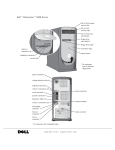
1
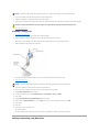
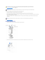
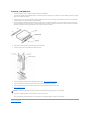
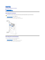
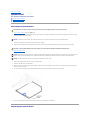
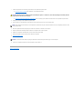
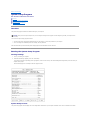
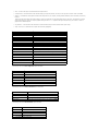
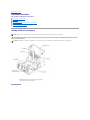
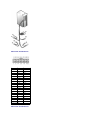
Dell™ Dimension™ 8300 Series Before You Begin
Turning Off Your Computer
Opening the Computer Cover
Technical Overview
Technical Specifications
Advanced Troubleshooting
System Setup Program
Removing and Installing Parts
Closing the Computer Cover
Notes, Notices, and Cautions
NOTE: A NOTE indicates important information that helps you make better use of your computer.
NOTICE: A NOTICE indicates either potential damage to hardware or loss of data and tells you how to avoid the problem.
CAUTION: A CAUTION indicates a potential for property damage, personal injury, or death.
Abbreviations and Acronyms
For a complete list of abbreviations and acronyms, see the Tell Me How help file.
If you purchased a Dell™ n Series computer, any references in this document to Microsoft® Windows® operating systems are not applicable.
Information in this document is subject to change without notice.
© 2003–2004 Dell Inc. All rights reserved.
Reproduction in any manner whatsoever without the written permission of Dell Inc. is strictly forbidden.
Trademarks used in this text: Dell, the DELL logo, and Dimension are trademarks of Dell Inc.; Intel and Pentium are registered trademarks of Intel Corporation; Microsoft and
Windows are registered trademarks of Microsoft Corporation.
Other trademarks and trade names may be used in this document to refer to either the entities claiming the marks and names or their products. Dell Inc. disclaims any
proprietary interest in trademarks and trade names other than its own.
March 2004 Rev. A03
Back to Contents Page
Advanced Troubleshooting
Dell™ Dimension™ 8300 Series Service Manual
Diagnostic Lights
Beep Codes
System Messages
Diagnostic Lights
To help you troubleshoot a problem, your computer is equipped with four lights on the back panel labeled "A," "B," "C," and "D." These lights can be yellow or
green. When the computer starts normally, the lights flash. After the computer starts, all four lights will display solid green. If the computer malfunctions, the
color and sequence of the lights identify the problem.
CAUTION: Before you begin any of the procedures in this section, follow the safety instructions in your Owner's Manual.
Light Pattern
Problem Description
Suggested Resolution
The computer is in a normal
off condition or a possible
pre-BIOS failure has
occurred.
Verify that the computer is plugged into a working electrical outlet and that you have pressed the power
button.
Memory modules are
detected, but a memory
failure has occurred.
l
l
l
l
A possible expansion card
failure has occurred.
1.
2.
3.
4.
If you have one memory module installed, reinstall the module and restart the computer.
If you have two or more memory modules installed, remove the modules, reinstall one module,
and then restart the computer. If the computer starts normally, reinstall an additional module.
Continue until you have identified a faulty module or reinstalled all modules without error.
If available, install properly working memory of the same type into your computer.
If the problem persists, contact Dell. See "Contacting Dell" in your Owner's Manual for technical
assistance.
Determine if a conflict exists by removing a card (not the video card) and then restarting the
computer.
If the problem persists, reinstall the card that you removed, remove a different card, and then
restart the computer.
Repeat this process for each card. If the computer starts normally, troubleshoot the last card
removed from the computer for resource conflicts (see "Resolving Software and Hardware
Incompatibilities" in your Owner's Manual).
If the problem persists, contact Dell. See "Contacting Dell" in your Owner's Manual for technical
assistance.
A possible video card failure
has occurred.
l
l
l
If the computer has a video card, remove the card and reinstall it, and restart the computer.
If the problem still exists, install a video card that you know works and restart the computer.
If the problem persists or the computer has integrated video, contact Dell. See "Contacting Dell" in
your Owner's Manual for technical assistance.
A possible floppy or hard
drive failure has occurred.
Reseat all power and data cables and restart the computer.
A possible USB failure has
occurred.
Reinstall all USB devices, check cable connections, and then restart the computer.
No memory modules are
detected.
l
Memory modules are
detected, but a memory
configuration or compatibility
error exists.
l
Other failure has occurred.
l
l
l
l
Reinstall all memory modules and restart the computer.
To eliminate the possibility of a faulty memory connector, remove all memory modules, reinstall one
memory module (if the computer supports a single module), and then restart the computer. If the
computer starts normally, move the memory module to a different connector and restart the
computer. Continue until you have identified a faulty connector or reinstalled all modules without
error.
Ensure that there are no special memory module/memory connector placement requirements.
Verify that the memory modules that you are installing are compatible with your computer.
If the problem persists, contact Dell. See "Contacting Dell" in your Owner's Manual for technical
assistance.
Ensure that the cables are properly connected from the hard drive, CD drive, and DVD drive to the
system board.
l
l
l
The computer is in a normal
operating condition after
POST.
If the problem persists, contact Dell. See "Contacting Dell" in your Owner's Manual for technical
assistance.
If there is an error message on your screen identifying a problem with a device (such as the floppy
drive or hard drive), check the device to ensure that it is functioning properly.
The operating system is attempting to boot from a device (such as the floppy drive or hard drive);
see "System Setup Screens" to ensure that the boot sequence is correct for the devices installed
on your computer.
None.
Beep Codes
Your computer might emit a series of beeps during start-up if the monitor cannot display errors or problems. This series of beeps, called a beep code,
identifies a problem. One possible beep code (code 1-3-1) consists of one beep, a burst of three beeps, and then one beep. This beep code tells you that the
computer encountered a memory problem.
Reseating the memory modules may fix the beep code errors in the following table. If the problem persists, see "Contacting Dell" in your Owner's Manual for
instructions on obtaining technical assistance. Code
Cause
1-3-1 through 2-4-4 Memory not being properly identified or used
4-3-1
Memory failure above address 0FFFFh
If you hear one of the following beep codes, see "Contacting Dell" in your Owner's Manual for instructions on obtaining technical assistance.
Code Cause
1-1-2 Microprocessor register failure
1-1-3 NVRAM
1-1-4 ROM BIOS checksum failure
1-2-1 Programmable interval timer
1-2-2 DMA initialization failure
1-2-3 DMA page register read/write failure
3-1-1 Slave DMA register failure
3-1-2 Master DMA register failure
3-1-3 Master interrupt mask register failure
3-1-4 Slave interrupt mask register failure
3-2-2 Interrupt vector loading failure
3-2-4 Keyboard Controller Test failure
3-3-1 NVRAM power loss
3-3-2 NVRAM configuration
3-3-4 Video Memory Test failure
3-4-1 Screen initialization failure
3-4-2 Screen retrace failure
3-4-3 Search for video ROM failure
4-2-1 No time tick
4-2-2 Shutdown failure
4-2-3 Gate A20 failure
4-2-4 Unexpected interrupt in protected mode
4-3-3 Timer-chip counter 2 failure
4-3-4 Time-of-day clock stopped
4-4-1 Serial or parallel port test failure
4-4-4 Cache test failure
System Messages
NOTE: If the message you received is not listed in the table, see the documentation for either the operating system or the program that was running
when the message appeared.
Message
Possible Cause
Corrective Action
8042 Gate-A20 error
The keyboard controller failed its test.
If you receive this message after you make changes in the system setup
program, enter the program and restore the original value(s).
Address Line Short!
An error in the address decoding circuitry in the
memory has occurred.
Reseat the memory modules.
C: Drive Error
The hard drive is not working or is not configured
correctly.
Ensure that the drive is installed correctly in the computer and defined
correctly in the system setup program.
Cache Memory Bad, Do
Not Enable Cache
The cache memory is not operating.
See "Contacting Dell" in your Owner's Manual for instructions on obtaining
technical assistance.
CH-2 Timer Error
An error is occurring on the timer on the system
board.
See "Contacting Dell" in your Owner's Manual for instructions on obtaining
technical assistance.
CMOS Battery State
Low
The system configuration information in the system
setup program is incorrect or the battery charge
may be low.
Enter the system setup program, verify the system configuration, and then
restart the computer.
C: Drive Failure
CMOS Checksum Failure
CMOS System Options
Not Set
CMOS Display Type
Mismatch
CMOS Memory Size
Mismatch
CMOS Time and Date
Not Set
Diskette Boot Failure
Drive A or B is present but has failed the BIOS POST. Ensure that the drive is installed correctly in the computer and defined
correctly in the system setup program. Check the interface cable at both
ends.
DMA Error
Error in the DMA controller on the system board.
The keyboard or system board may need to be replaced.
The BIOS cannot communicate with the floppy drive
or hard drive controller.
Ensure that the floppy drive or the hard drive is installed correctly in the
computer and defined correctly in the system setup program. Check the
interface cable at both ends.
An interrupt channel on the system board failed to
POST.
The keyboard or system board may need to be replaced.
Invalid Boot Diskette
The operating system cannot be located on drive A
or drive C.
Enter the system setup program and confirm that drive A or drive C is
properly identified.
Keyboard Error
The BIOS has detected a stuck key.
Ensure that nothing is resting on the keyboard; if a key appears to be stuck,
carefully pry it up. If the problem persists, you may need to replace the
keyboard.
KB/Interface Error
An error occurred with the keyboard connector.
Ensure that nothing is resting on the keyboard; if a key appears to be stuck,
carefully pry it up. If the problem persists, you may need to replace the
keyboard.
No ROM Basic
The operating system cannot be located on drive A
or drive C.
Enter the system setup program and confirm that drive A or drive C is
properly identified.
DMA 1 Error
DMA 2 Error
FDD Controller
Failure
HDD Controller
Failure
INTR1 Error
INTR2 Error
Back to Contents Page
Back to Contents Page
Battery
Dell™ Dimension™ 8300 Series Service Manual
CAUTION: Before you begin any of the procedures in this section, follow the safety instructions in your Owner's Manual.
A coin-cell battery maintains computer configuration, date, and time information. The battery can last several years.
If you have to repeatedly reset time and date information after turning on the computer, replace the battery.
CAUTION: A new battery can explode if it is incorrectly installed. Replace the battery only with the same or equivalent type recommended by the
manufacturer. Discard used batteries according to the manufacturer's instructions.
To replace the battery:
1.
Record all the screens in the system setup program so that you can restore the correct settings in step 12.
2.
Shut down the computer through the Start menu.
3.
Ensure that your computer and attached devices are turned off. If your computer and attached devices did not automatically turn off when you shut
down your computer, turn them off now.
NOTICE: To disconnect a network cable, first unplug the cable from your computer, and then unplug it from the network wall jack.
4.
Turn off any attached devices and disconnect them from their electrical outlets.
5.
Disconnect the computer power cable from the wall outlet, and then press the power button to ground the system board.
CAUTION: To guard against electrical shock, always unplug your computer from the electrical outlet before opening the cover.
6.
Open the computer cover.
NOTICE: Before touching anything inside your computer, ground yourself by touching an unpainted metal surface, such as the metal at the back of the
computer. While you work, periodically touch an unpainted metal surface to dissipate any static electricity that could harm internal components.
7.
Locate the battery socket on the system board.
NOTICE: If you pry the battery out of its socket with a blunt object, be careful not to touch the system board with the object. Ensure that the object is
inserted between the battery and the socket before you attempt to pry out the battery. Otherwise, you may damage the system board by prying off
the socket or by breaking circuit traces on the system board.
8.
Remove the battery by carefully prying it out of its socket with your fingers or with a blunt, nonconducting object such as a plastic screwdriver.
9.
Insert the new battery into the socket with the side labeled "+" facing up, and snap the battery into place.
10.
Close the computer cover.
NOTICE: To connect a network cable, first plug the cable into the network wall jack and then plug it into the computer.
11.
Connect your computer and devices to electrical outlets, and turn them on.
12.
Enter the system setup program and restore the settings you recorded in step 1.
13.
Properly dispose of the old battery. See the safety instructions in your Owner's Manual.
Back to Contents Page
Back to Contents Page
Before You Begin
Dell™ Dimension™ 8300 Series Service Manual
Getting Started
Recommended Tools
Shutting Down Your Computer
Getting Started
This section provides procedures for removing and installing the components in your computer. Unless otherwise noted, each procedure assumes that the
following conditions exist:
l
You have performed the steps in "Shutting Down Your Computer."
l
You have read the safety information in your Owner’s Manual.
Recommended Tools
The procedures in this document may require the following tools:
l
Small flat-blade screwdriver
l
Phillips screwdriver
l
Flash BIOS update program floppy disk or CD
Shutting Down Your Computer
Use the following safety guidelines to help protect your computer from potential damage and to ensure your own personal safety.
CAUTION: Before you begin any of the procedures in this section, follow the safety instructions in the Owner's Manual.
NOTICE: Only a certified service technician should perform repairs on your computer. Damage due to servicing that is not authorized by Dell is not
covered by your warranty.
CAUTION: Handle components and cards with care. Do not touch the components or contacts on a card. Hold a card by its edges or by its metal
mounting bracket. Hold a component such as a microprocessor by its edges, not by its pins.
NOTICE: When you disconnect a cable, pull on its connector or on its strain-relief loop, not on the cable itself. Some cables have a connector with
locking tabs; if you are disconnecting this type of cable, press in on the locking tabs before you disconnect the cable. As you pull connectors apart, keep
them evenly aligned to avoid bending any connector pins. Also, before you connect a cable, ensure that both connectors are correctly oriented and
aligned.
NOTICE: To avoid damaging the computer, perform the following steps before you begin working inside the computer.
1.
Shut down the computer.
2.
Ensure that the computer and any attached devices are turned off. If your computer and attached devices did not automatically turn off when you shut
down your computer, press and hold the power button for 4 seconds.
NOTICE: To disconnect a network cable, first unplug the cable from your computer and then unplug it from the network wall jack.
3.
Disconnect any telephone or telecommunication lines from the computer.
4.
Disconnect your computer and all attached devices from their electrical outlets, and then press the power button to ground the system board.
5.
Remove the computer stand, if it is attached.
CAUTION: To guard against electrical shock, always unplug your computer from the electrical outlet before opening the cover.
6.
Open the computer cover.
NOTICE: Before touching anything inside your computer, ground yourself by touching an unpainted metal surface, such as the metal at the back of the
computer. While you work, periodically touch an unpainted metal surface to dissipate any static electricity that could harm internal components.
Back to Contents Page
Back to Contents Page
Cards
Dell™ Dimension™ 8300 Series Service Manual
PCI Cards
AGP Cards
PCI Cards
CAUTION: Before you begin any of the procedures in this section, follow the safety instructions listed in your Owner's Manual.
CAUTION: To guard against electrical shock, always unplug your computer from the electrical outlet before opening the cover.
Your Dell™ computer provides slots for up to four 32-bit, 33-MHz cards.
If you are installing or replacing a card, follow the procedures in the next section. If you are removing but not replacing a card, see "Removing a Card."
Installing a PCI Card
CAUTION: Before you begin any of the procedures in this section, follow the safety instructions listed in your Owner's Manual.
1.
If you are replacing a card, remove the current driver for the card from the operating system.
2.
Shut down the computer through the Start menu.
3.
Ensure that your computer and attached devices are turned off. If your computer and attached devices did not automatically turn off when you shut
down your computer, turn them off now.
NOTICE: To disconnect a network cable, first unplug the cable from your computer and then unplug it from the network wall jack.
4.
Disconnect any telephone or telecommunication lines from the computer.
5.
Disconnect your computer and all attached devices from their electrical outlets, and then press the power button to ground the system board.
CAUTION: To guard against electrical shock, always unplug your computer from the electrical outlet before opening the cover.
6.
Open the computer cover.
7.
Press the lever on the card retention arm and raise the retention arm.
8.
If you are installing a new card, remove the filler bracket to create a card-slot opening. Then continue with step 10.
9.
If you are replacing a card that is already installed in the computer, remove the card.
If necessary, disconnect any cables connected to the card. Grasp the card by its top corners, and ease it out of its connector.
10.
Prepare the card for installation.
See the documentation that came with the card for information on configuring the card, making internal connections, or otherwise customizing it for your
computer.
CAUTION: Some network adapters automatically start the computer when they are connected to a network. To guard against electrical shock, be
sure to unplug your computer from its electrical outlet before installing any cards. Verify that the standby power light on the system board is off.
11.
Place the card in the connector and press down firmly. Ensure that the card is fully seated in the slot.
If the card is full-length, insert the end of the card into the card guide bracket as you lower the card toward its connector on the system board. Insert
the card firmly into the card connector on the system board.
12.
Before you lower the retention arm, ensure that:
l
The tops of all cards and filler brackets are flush with the alignment bar.
l
The notch in the top of the card or filler bracket fits around the alignment guide.
Press the arm into place, securing the card(s) in the computer.
NOTICE: Do not route card cables over or behind the cards. Cables routed over the cards can prevent the computer cover from closing properly or
cause damage to the equipment.
13.
Connect any cables that should be attached to the card.
See the documentation for the card for information about the card's cable connections.
NOTICE: To connect a network cable, first plug the cable into the network wall jack and then plug it into the computer.
14.
Close the computer cover, reconnect the computer and devices to electrical outlets, and turn them on.
15.
Install any drivers required for the card as described in the card documentation.
Removing a PCI Card
CAUTION: Before you begin any of the procedures in this section, follow the safety instructions in your Owner's Manual.
1.
Shut down the computer through the Start menu.
2.
Ensure that your computer and attached devices are turned off. If your computer and attached devices did not automatically turn off when you shut
down your computer, turn them off now.
NOTICE: To disconnect a network cable, first unplug the cable from your computer and then unplug it from the network wall jack.
3.
Disconnect any telephone or telecommunication lines from the computer.
4.
Disconnect your computer and all attached devices from their electrical outlets, and then press the power button to ground the system board.
CAUTION: To guard against electrical shock, always unplug your computer from the electrical outlet before opening the cover.
5.
Open the computer cover.
6.
Press the lever on the card retention arm and raise the retention arm.
7.
If necessary, disconnect any cables connected to the card.
8.
Grasp the card by its top corners, and ease it out of its connector.
9.
If you are removing the card permanently, install a filler bracket in the empty card-slot opening.
If you need a filler bracket, contact Dell. See "Contacting Dell" in your Owner's Manual for technical assistance
10.
Lower the retention arm and press it into place, securing the card(s) in the computer.
NOTICE: To connect a network cable, first plug the cable into the network wall jack and then plug it into the computer.
11.
Close the computer cover, reconnect the computer and devices to electrical outlets, and then turn them on.
12.
Remove the card's driver from the operating system.
AGP Cards
CAUTION: Before you begin any of the procedures in this section, follow the safety instructions in your Owner's Manual.
Your Dell computer provides a connector for an AGP card.
1.
Shut down the computer through the Start menu.
2.
Ensure that your computer and attached devices are turned off. If your computer and attached devices did not automatically turn off when you shut
down your computer, turn them off now.
NOTICE: To disconnect a network cable, first unplug the cable from your computer and then unplug it from the network wall jack.
3.
Disconnect any telephone or telecommunication lines from the computer.
4.
Disconnect your computer and all attached devices from their electrical outlets, and then press the power button to ground the system board.
CAUTION: To guard against electrical shock, always unplug your computer from the electrical outlet before opening the cover.
5.
Open the computer cover.
Removing an AGP Card
1.
Remove the filler bracket by raising the hinged lever and sliding the bracket up.
2.
Press the card lever toward the PCI connector.
3.
Pull the card up and out of the card clip.
Installing an AGP Card
1.
To add or replace the card, press the card lever toward the PCI connector and gently press the card into the AGP connector until it clicks into place.
2.
Release the card lever, ensuring that the tab fits into the notch on the front end of the card.
3.
Secure the card by lowering the hinged lever on the back panel.
4.
Close the computer cover.
5.
Connect the monitor cable to the card's video connector.
NOTICE: To connect a network cable, first plug the cable into the network wall jack and then plug it into the computer.
6.
Connect your computer and devices to electrical outlets, and turn them on.
Back to Contents Page
Back to Contents Page
Closing the Computer Cover
Dell™ Dimension™ 8300 Series Service Manual
1.
Ensure that all cables are connected, and fold cables out of the way.
Gently pull the power cables toward you so that they do not get caught underneath the drives.
2.
Ensure that no tools or extra parts are left inside the computer.
3.
Close the cover:
a.
Pivot the cover down.
b.
Press down on the right side of the cover until it closes.
c.
Press down on the left side of the cover until it closes.
d.
Ensure that both sides of the cover are locked. If not, repeat all of step 3.
NOTICE: To connect a network cable, first plug the cable into the network wall jack and then plug it into the computer.
4.
Connect your computer and devices to electrical outlets, and turn them on.
Back to Contents Page
Back to Contents Page
Opening the Computer Cover
Dell™ Dimension™ 8300 Series Service Manual
CAUTION: Before you begin any of the procedures in this section, follow the safety instructions in your Owner's Manual.
1.
Shut down the computer through the Start menu.
2.
Ensure that your computer and attached devices are turned off. If your computer and attached devices did not automatically turn off when you shut
down your computer, turn them off now.
NOTICE: To disconnect a network cable, first unplug the cable from your computer and then unplug it from the network wall jack.
3.
Disconnect any telephone or telecommunication lines from the computer.
4.
Disconnect your computer and all attached devices from their electrical outlets, and then press the power button to ground the system board.
CAUTION: To guard against electrical shock, always unplug your computer from the electrical outlet before opening the cover.
NOTICE: Ensure that sufficient space exists to support the open cover—at least 30 cm (1 ft) of desk top space.
5.
Lay the computer on its side so that the arrow on the bottom of the computer points up. 6.
Open the cover:
a.
Facing the back of the computer, press the release button on the right side of the computer with one hand while pulling up on the top of the
cover with the other hand.
b.
Press the release button on the left side of the computer with one hand while pulling up on the top of the cover with the other hand.
c.
Hold the bottom of the computer with one hand, and then pull open the cover with the other hand.
Back to Contents Page
Back to Contents Page
Drives
Dell™ Dimension™ 8300 Series Service Manual
Replacing the Hard Drive
Adding a Second Hard Drive
Adding or Replacing a Floppy Drive
Adding or Replacing a CD/DVD Drive
Your computer supports one floppy drive and a maximum combination of up to four of any of the following drives.
NOTE: Install only IDE hard drives or serial ATA hard drives in your computer. You cannot install both types of drives.
l
Two hard drives (IDE, Serial ATA)
l
Two CD or DVD drives
l
One Zip drive
Replacing the Hard Drive
CAUTION: Before you begin any of the procedures in this section, follow the safety instructions in your Owner's Manual.
NOTICE: To avoid damage to the drive, do not set it on a hard surface. Instead, set the drive on a surface, such as a foam pad, that will sufficiently
cushion it.
1.
If you are replacing a hard drive that contains data you want to keep, back up your files before you begin this procedure.
2.
Shut down the computer through the Start menu.
NOTICE: To disconnect a network cable, first unplug the cable from your computer, and then unplug it from the network wall jack.
3.
Turn off any attached devices and disconnect them from their electrical outlets.
4.
Disconnect any telephone or telecommunication lines from the computer.
5.
Disconnect the computer power cable from the wall outlet, and then press the power button to ground the system board.
6.
Ground yourself by touching an unpainted metal surface on the chassis, such as the metal around the card-slot openings at the back of the computer,
before touching anything inside your computer.
While you work, periodically touch an unpainted metal surface on the computer chassis to dissipate any static electricity that might harm internal
components.
NOTICE: To guard against electrical shock, always unplug your computer from the electrical outlet before opening the cover.
7.
Open the computer cover.
Removing a Hard Drive
1.
Disconnect the power and hard-drive cables from the drive.
2.
Press in on the tabs on each side of the drive and slide the drive up and out.
Installing a Hard Drive
1.
Unpack the replacement hard drive, and prepare it for installation.
2.
Check the documentation for the drive to verify that it is configured for your computer.
3.
If your replacement hard drive does not have the bracket rails attached, remove the rails from the old drive by removing the two screws that secure
each rail to the drive. Attach the bracket rails to the new drive by aligning the screw holes on the drive with the screw holes on the bracket rails and
then inserting and tightening all four screws (two screws on each rail).
4.
Install the hard drive into the computer by gently sliding the drive into place until you hear or feel it securely click.
NOTICE: Match the colored strip on the cable with pin 1 on the drive (pin 1 is marked as "1").
5.
Connect the power and hard-drive cables to the drive.
6.
Check all connectors to be certain that they are properly cabled and firmly seated.
7.
Close the computer cover.
NOTICE: To connect a network cable, first plug the cable into the network wall jack and then plug it into the computer.
8.
Connect your computer and devices to electrical outlets, and turn them on.
See the documentation that came with the drive for instructions on installing any software required for drive operation.
Adding a Second Hard Drive
CAUTION: Before you begin any of the procedures in this section, follow the safety instructions in your Owner's Manual.
NOTICE: To avoid damage to the drive, do not set it on a hard surface. Instead, set the drive on a surface, such as a foam pad, that will sufficiently
cushion it.
1.
Check the documentation for the drive to verify that it is configured for your computer.
2.
Shut down the computer through the Start menu.
NOTICE: To disconnect a network cable, first unplug the cable from your computer and then unplug it from the network wall jack.
3.
Turn off any attached devices and disconnect them from their electrical outlets.
4.
Disconnect any telephone or telecommunication lines from the computer.
5.
Disconnect your computer and all attached devices from their electrical outlets, and then press the power button to ground the system board.
CAUTION: To guard against electrical shock, always unplug your computer from the electrical outlet before opening the cover.
6.
Open the computer cover.
7.
Remove the two green plastic rails from the inside of the hard-drive bay by gently pulling the rails up and out of the bay.
8.
Attach the rails to the hard drive using the two screws attached to the rails.
Ensure that the rail tabs are positioned at the back of the hard drive.
NOTICE: Do not install any drive into the lower hard-drive bay until you have removed the green drive rails from the inside of the hard-drive bay.
9.
Remove the first hard drive from the upper bay and install it in the lower bay:
a.
Disconnect the power and the hard-drive cables from the back of the first hard drive.
b.
Press in the two green rail tabs and pull the first hard drive out of the upper bay.
c.
Gently slide the first hard drive into the lower bay until you hear or feel a click.
d.
Reconnect the power and hard-drive cables to the back of the first hard drive.
10.
Gently slide the new hard drive into the upper bay until you hear or feel a click.
11.
Connect a power cable to the drive.
NOTICE: Match the colored strip on the cable with pin 1 on the drive.
12.
Locate the extra connector on the drive cable that is attached to your first hard drive and attach the connector to the second hard drive.
Your computer uses cable-select drive cables. This means that the device connected to the end connector of the drive cable is the master device and
the device connected to the middle connector is the slave device. Be sure that the jumper setting on the new device is set for "cable select" (see the
documentation that came with the drive for information).
13.
Close the computer cover.
NOTICE: To connect a network cable, first plug the cable into the network wall jack and then plug it into the computer.
14.
Connect your computer and devices to electrical outlets, and turn them on.
15.
See the documentation that came with the drive for instructions on installing any software required for drive operation.
Adding or Replacing a Floppy Drive
CAUTION: Before you begin any of the procedures in this section, follow the safety instructions in your Owner's Manual.
1.
Shut down the computer through the Start menu.
NOTICE: To disconnect a network cable, first unplug the cable from your computer and then unplug it from the network wall jack.
2.
Turn off any attached devices and disconnect them from their electrical outlets.
3.
Disconnect any telephone or telecommunication lines from the computer.
4.
Disconnect your computer and all attached devices from their electrical outlets, and then press the power button to ground the system board.
CAUTION: To guard against electrical shock, always unplug your computer from the electrical outlet before opening the cover.
5.
Open the computer cover.
Installing a Floppy Drive
1.
Remove the front-panel inserts.
2.
Gently slide the drive into place until the tabs securely click into position.
3.
Attach the floppy-drive cable to the floppy drive and to the system board floppy-drive connector.
Ensure that you route the floppy-drive cable through the cable restraint located on the side of the floppy-drive bay.
4.
Attach the floppy-drive power cable to the floppy drive.
5.
Check all cable connections and fold cables out of the way to provide airflow for the fan and cooling vents.
6.
Close the computer cover.
NOTICE: To connect a network cable, first plug the cable into the network wall jack and then plug it into the computer.
7.
Connect your computer and devices to electrical outlets, and turn them on.
8.
After you turn on your computer, press <F2> when you are prompted to enter setup mode.
9.
Highlight Drive Configuration and press <Enter>.
10.
Use the left and right arrows to change Diskette Drive A from Not Installed to 3.5 inch, 1.44 MB.
11.
Press <Enter>.
12.
Highlight Integrated Devices (LegacySelect Options) and press <Enter>.
13.
Make sure that the Diskette Interface entry is set to Auto. If necessary, use the left and right arrows to set it to Auto.
14.
Press <Enter>.
15.
Press <Esc>.
16.
Press <Enter> to save changes and exit.
The computer restarts.
See the documentation that came with the drive for instructions on installing any software required for drive operation.
Adding or Replacing a CD/DVD Drive
CAUTION: Before you begin any of the procedures in this section, follow the safety instructions in your Owner's Manual.
1.
Shut down the computer through the Start menu.
NOTICE: To disconnect a network cable, first unplug the cable from your computer, and then unplug it from the network wall jack.
2.
Turn off any attached devices and disconnect them from their electrical outlets.
3.
Disconnect any telephone or telecommunication lines from the computer.
4.
Disconnect the computer power cable from the wall outlet, and then press the power button to ground the system board.
5.
Ground yourself by touching an unpainted metal surface on the chassis, such as the metal around the card-slot openings at the back of the computer,
before touching anything inside your computer.
While you work, periodically touch an unpainted metal surface on the computer chassis to dissipate any static electricity that might harm internal
components.
NOTICE: To guard against electrical shock, always unplug your computer from the electrical outlet before opening the cover.
6.
Open the computer cover.
Removing a CD/DVD Drive
1.
Disconnect the power, audio, and CD/DVD drive cables from the back of the drive.
2.
Press inward on the two tabs on the sides of the drive, and then slide the drive upward and remove it from the drive bay.
Installing a CD/DVD Drive
1.
If you are installing a new drive, unpack the drive and prepare it for installation.
Check the documentation that accompanied the drive to verify that the drive is configured for your computer. If you are installing an IDE drive, configure
the drive for the cable select setting.
2.
Connect the new drive to the set of rails that are attached to the inside of the cover. If a set of rails is not attached inside the cover, contact Dell. See
"Contacting Dell" in your Owner's Manual for technical assistance
3.
If you are installing a replacement drive and the new drive does not have the bracket rails attached, remove the rails from the old drive by removing
the two screws that secure each rail to the drive. Attach the bracket to the new drive by aligning the screw holes on the drive with the screw holes on
the bracket rails and then inserting and tightening all four screws (two screws on each rail).
4.
Gently slide the drive into place until the tabs securely click into position.
5.
Connect the power, audio, and CD/DVD drive cables to the drive.
6.
If you are installing a new CD/DVD drive rather than replacing a drive, remove the front-panel insert.
7.
If you are installing a drive that has its own controller card, install the controller card in a card slot.
8.
Check all cable connections, and fold cables out of the way to provide airflow for the fan and cooling vents.
9.
Close the computer cover.
NOTICE: To connect a network cable, first plug the cable in to the network wall jack and then plug it in to the computer.
10.
Connect your computer and devices to their electrical outlets, and turn them on.
See the documentation that came with the drive for instructions on installing any software required for drive operation.
Back to Contents Page
Back to Contents Page
Front Panel
Dell™ Dimension™ 8300 Series Service Manual
Removing the Front Panel
Removing the Front-Panel Insert
Removing the Front Panel
CAUTION: Before you begin any of the procedures in this section, follow the safety instructions in your Owner's Manual.
1.
Shut down the computer through the Start menu.
2.
Disconnect the computer power cable from the electrical outlet.
3.
Remove the front-panel door by gently snapping it off the two hinge arms.
Removing the Front-Panel Insert
Remove the front-panel insert before you install the floppy drive:
1.
Open the computer cover to a 90-degree angle.
2.
Locate the insert that is in front of the drive bay that you want to use.
3.
From inside the computer, press in the release tab of the insert.
4.
From outside the computer, pull the insert away from the computer's front panel.
5.
Remove the insert from the insert frame by pressing on the four tabs.
6.
Reattach the empty insert frame over the front of the drive bay.
The insert frame fits only one way.
Back to Contents Page
Back to Contents Page
Memory
Dell™ Dimension™ 8300 Series Service Manual
DDR Memory Overview
Installing Memory
You can increase your computer memory by installing memory modules on the system board. For information on the type of memory supported by your
computer, see "Memory" in "Technical Specifications."
DDR Memory Overview
DDR memory modules should be installed in pairs of matched memory size. This means that if you purchased your computer with 256 MB of memory installed
and you want to add another 256 MB of memory, you must install it in the appropriate connector. If the DDR memory modules are not installed in matched
pairs, the computer will continue to operate, but with a slight reduction in performance.
NOTE: Always install DDR memory modules in the order indicated on the system board.
The recommended memory configurations are:
l
A pair of matched memory modules installed in connectors DIMM1 and DIMM2
or
l
A pair of matched memory modules installed in connectors DIMM1 and DIMM2 and another matched pair installed in connectors DIMM3 and DIMM4
Additional memory recommendations include:
l
Do not install ECC memory modules.
l
If you install mixed pairs PC2700 (DDR 333-MHz) and PC3200 (DDR 400-MHz) of memory modules, they function at the slowest speed of the modules
you install.
l
Be sure to install a single memory module in DIMM 1 or the connector closest to the processor before you install modules in the other connectors.
NOTICE: If you remove your original memory modules from the computer during a memory upgrade, keep them separate from any new modules that
you may have, even if you purchased the new modules from Dell. You should install your original memory modules in pairs either in connectors DIMM1
and DIMM2 or connectors DIMM3 and DIMM4. If possible, do not pair an original memory module with a new memory module. Otherwise, your computer
may not function at optimal performance.
NOTE: Memory purchased from Dell is covered under your computer warranty.
Addressing Memory with 4-GB Configurations
Your computer supports a maximum of 4 GB of memory when you use four 1-GB DIMMs. Current operating systems, such as Microsoft® Windows® XP, can
only use a maximum of 4 GB of address space; however, the amount of memory available to the operating system is less than 4 GB. Certain components
within the computer require address space in the 4-GB range. Any address space reserved for these components cannot be used by computer memory. Installing Memory
CAUTION: Before you begin any of the procedures in this section, follow the safety instructions in your Owner's Manual.
1.
Shut down the computer through the Start menu.
2.
Ensure that your computer and attached devices are turned off. If your computer and attached devices did not automatically turn off when you shut
down your computer, turn them off now.
NOTICE: To disconnect a network cable, first unplug the cable from your computer and then unplug it from the network wall jack.
3.
Disconnect any telephone or telecommunication lines from the computer.
4.
Disconnect your computer and all attached devices from their electrical outlets, and then press the power button to ground the system board.
CAUTION: To guard against electrical shock, always unplug your computer from the electrical outlet before opening the cover.
5.
Open the computer cover.
6.
Lay the computer on its side so that the system board is on the bottom of the inside of the computer.
7.
If necessary, remove a memory module:
a.
b.
Press out the securing clip at each end of the memory module connector.
Grasp the module and pull up.
If the module is difficult to remove, gently ease the module back and forth to remove it from the connector.
8.
To insert a module, press out the securing clip at each end of the memory module connector.
9.
Align the notch on the bottom of the module with the crossbar in the connector.
NOTICE: To avoid breaking the memory module, do not press near the middle of the module.
10.
Insert the module straight down into the connector, ensuring that it fits into the vertical guides at each end of the connector. Press firmly on the ends
of the module until it snaps into place.
If you insert the module correctly, the securing clips snap into the cutouts at each end of the module.
11.
Close the computer cover.
NOTICE: To connect a network cable, first plug the cable into the network wall jack and then plug it into the computer.
12.
Connect your computer and devices to electrical outlets, and then turn them on.
13.
Click the Start button, right-click My Computer, and then click Properties.
14.
Click the General tab.
15.
To verify that the memory is installed correctly, check the amount of memory (RAM) listed.
Back to Contents Page
Back to Contents Page
Microprocessor
Dell™ Dimension™ 8300 Series Service Manual
Removing the Microprocessor
Installing the Microprocessor
Removing the Microprocessor
CAUTION: Before you begin any of the procedures in this section, follow the safety instructions in your Owner's Manual.
1.
Shut down the computer through the Start menu.
2.
Ensure that your computer and attached devices are turned off. If your computer and attached devices did not automatically turn off when you shut
down your computer, turn them off now.
NOTICE: To disconnect a network cable, first unplug the cable from your computer and then unplug it from the network wall jack.
3.
Disconnect any telephone or telecommunication lines from the computer.
4.
Disconnect your computer and all attached devices from their electrical outlets, and then press the power button to ground the system board.
CAUTION: To guard against electrical shock, always unplug your computer from the electrical outlet before you open the cover.
5.
Open the computer cover.
NOTICE: Before touching anything inside your computer, ground yourself by touching an unpainted metal surface, such as the metal at the back of the
computer. While you work, periodically touch an unpainted metal surface to dissipate any static electricity that could harm internal components.
6.
Disconnect the cooling fan power cable from the FAN2 connector on the system board.
7.
Disconnect the power cable from the PWR connector on the system board.
8.
Lift up the airflow shroud.
CAUTION: The heat sink can get very hot during normal operation. Be sure that the heat sink has had sufficient time to cool before you touch it.
9.
Remove the heat sink:
a.
Release the retention module clip by pressing in on the tab and lifting the retention module clip up.
b.
Pull the release lever out until the heat sink is released.
c.
Lift the heat sink away from the microprocessor.
NOTICE: Lay the heat sink down with the thermal grease facing upward.
NOTICE: If you are installing a microprocessor upgrade kit from Dell™, discard the original heat sink. If you are not installing a microprocessor upgrade
kit from Dell, reuse the original heat sink and blower when you install your new microprocessor.
NOTICE: Be careful not to bend any of the pins when you remove the microprocessor from the socket. Bending the pins can permanently damage the
microprocessor.
11.
Remove the microprocessor from the socket.
Leave the release lever extended in the release position so that the socket is ready for the new microprocessor.
Installing the Microprocessor
NOTICE: Ground yourself by touching an unpainted metal surface on the back of the computer.
NOTICE: Be careful not to bend any of the pins when you unpack the microprocessor. Bending the pins can permanently damage the microprocessor. If
any of the pins on the microprocessor appears to be bent, see "Contacting Dell" in the Owner's Manual for instructions on obtaining technical assistance.
1.
Unpack the new microprocessor.
NOTICE: You must position the microprocessor correctly in the socket to avoid permanent damage to the microprocessor and the computer when you
turn on the computer.
2.
If the release lever on the socket is not fully extended, move it to that position.
3.
Align the pin-1 corners of the microprocessor and socket.
NOTICE: When you place the microprocessor in the socket, ensure that all of the pins fit into the corresponding holes on the socket.
4.
Set the microprocessor lightly in the socket and ensure that all pins are headed into the correct holes. Do not use force, which could bend the pins if the
microprocessor is misaligned. When the microprocessor is positioned correctly, press it with minimal pressure to seat it.
5.
When the microprocessor is fully seated in the socket, pivot the release lever back toward the socket until it snaps into place to secure the
microprocessor.
NOTICE: If you are not installing a microprocessor upgrade kit from Dell, reuse the original heat-sink assembly when you replace the microprocessor.
If you installed a microprocessor replacement kit from Dell, return the original heat-sink assembly and microprocessor to Dell in the same package in
which your replacement kit was sent.
6.
Install the heat sink:
a.
Insert the notched end of the heat sink onto the end of the retention base that is opposite the hinge.
b.
Lower the heat sink until it fits securely in the base.
c.
When the heat sink is secured, pivot the retention module clip back until the tab snaps into place to secure the heat sink.
7.
Lower the airflow shroud over the heat sink.
8.
Reconnect the cooling fan power cable to the FAN2 connector on the system board.
9.
Reconnect the power cable to the PWR connector on the system board.
10.
Close the computer cover.
NOTICE: To connect a network cable, first plug the cable into the network wall jack and then plug it into the computer.
11.
Connect your computer and devices to electrical outlets, and turn them on.
Back to Contents Page
Back to Contents Page
Removing and Installing Parts
Dell™ Dimension™ 8300 Series Service Manual
Cards
Microprocessor
Memory
System Board
Front Panel
Power Supply
Drives
Battery
Back to Contents Page
Back to Contents Page
Power Supply
Dell™ Dimension™ 8300 Series Service Manual
Removing the Power Supply
Replacing the Power Supply
Removing the Power Supply
CAUTION: Before you begin any of the procedures in this section, follow the safety instructions in your Owner's Manual.
1.
Shut down the computer through the Start menu.
2.
Ensure that your computer and attached devices are turned off. If your computer and attached devices did not automatically turn off when you shut
down your computer, turn them off now.
NOTICE: To disconnect a network cable, first unplug the cable from your computer and then unplug it from the network wall jack.
3.
Disconnect any telephone or telecommunication lines from the computer.
4.
Disconnect your computer and all attached devices from their electrical outlets, and then press the power button to ground the system board.
CAUTION: To guard against electrical shock, always unplug your computer from the electrical outlet before opening the cover.
5.
Open the computer cover.
NOTICE: Before touching anything inside your computer, ground yourself by touching an unpainted metal surface, such as the metal at the back of the
computer. While you work, periodically touch an unpainted metal surface to dissipate any static electricity that could harm internal components.
6.
Disconnect the DC power cables from the system board and the drives.
Note the routing of the DC power cables underneath the tabs in the computer frame as you remove them from the system board and drives. You must
route these cables properly when you replace them to prevent their being pinched or crimped.
7.
Remove the two screws that attach the power supply to the back of the computer frame.
8.
Press the release button located on the floor of the computer frame.
9.
Slide the power supply toward the front of the computer approximately 1 inch.
10.
Lift the power supply up and out of the computer.
Replacing the Power Supply
1.
Slide the power supply into place.
2.
On the small mini-tower computer, replace the two screws that secure the power supply to the back of the computer frame.
3.
Reconnect the DC power cables.
4.
Connect the AC power cable to the connector.
5.
Run the cables underneath the clips, and press the clips to close them over the cables.
6.
Close the computer cover.
NOTICE: To connect a network cable, first plug the cable into the network wall jack and then plug it into the computer.
7.
Connect your computer and devices to electrical outlets, and turn them on.
Back to Contents Page
Back to Contents Page
Technical Specifications
Dell™ Dimension™ 8300 Series Service Manual
Microprocessor
Drives
Memory
Connectors
Computer Information
Controls and Lights
Video
Power
Audio
Physical
Expansion Bus
Environmental
Microprocessor
Microprocessor type
Intel® Pentium® 4 microprocessor (2.4, 2.6, 2.8, 3.0,
3.2, and 3.4 for 800 FSB, and 2.4, 2.66, 2.8, and 3.06
for 533 FSB)
L1 cache
8 KB
L2 cache
512-KB or 1-MB pipelined-burst, eight-way set
associative, write-back SRAM
L3 cache
2 MB
NOTE: L3 cache is available only with Intel Pentium 4
Extreme Edition processors that support HyperThreading technology.
Memory
Type
DDR 333 or 400 (non-ECC)
Memory connectors
four
Memory capacities
128-, 256-, 512-MB, and 1-GB non-ECC
Minimum memory
256 MB
Maximum memory
4 GB
NOTE: See "Addressing Memory with 4-GB
Configurations" for the amount of memory available
to the operating system. BIOS address
F8000h
Computer Information
System chip set
Intel 875P
DMA channels
eight
Interrupt levels
15
BIOS chip
4 Mb
NIC
integrated PCI Network Interface
System clock
533- or 800-MHz data rate
Video
Type
AGP 8X
Audio
Type
Analog Devices AD1980 AC97 Codec
NOTE: This audio type is present only on computers
with integrated sound capabilities.
Expansion Bus Bus types
PCI and AGP
Bus speed
PCI: 33 MHz
AGP: 133 MHz
AGP
connector
one
connector size
172 pins
connector data width (maximum)
32 bits
bus protocols
8x/4x/2x modes at 1.5 V
PCI
connectors
four
connector size
120 pins
connector data width (maximum)
32 bits
Drives
Externally accessible
two 3.5-inch bays
two 5.25-inch bays
Available devices
ATA-66 or ATA-100 Ultra DMA hard drive, serial ATA
drive, CD drive, Zip drive, DVD drive, CD-RW drive,
DVD/CD-RW combo drive, and DVD+RW drive
Internally accessible
two bays for 1-inch–high hard drives
Connectors Externally accessible:
Serial
9-pin connector; 16550C-compatible
Parallel
25-hole connector (bidirectional)
Video
15-hole connector
Network Adapter
RJ45 connector
PS/2 (keyboard and mouse)
6-pin mini-DIN connector
USB
two front-panel and six back-panel
USB 2.0–compliant connectors
5.1 Audio
five connectors for line-in, line-out, microphone,
surround, and center/Low-Frequency Effects (LFE)
channel; one front panel connector for headphones
NOTE: These audio connectors are present only on
computers with integrated sound capabilities.
System board connectors:
Primary IDE channel
40-pin connector on PCI local bus
Secondary IDE channel
40-pin connector on PCI local bus
Serial ATA drive
two 7-pin connectors
Floppy drive
34-pin connector
Telephony (ATAPI)
4-pin connector
CD Audio (ATAPI)
4-pin connector
Fan
3-pin connector
Controls and Lights
Power control
push button
Power light
green light on power button—blinking green in sleep
states; solid green for power-on states
Hard-drive access light
green
Link integrity light (on integrated network adapter)
green light for 10-Mb operation; orange light for 100Mb operation
Diagnostic code lights
four bicolor (amber and green) located on back panel
Power DC power supply:
Wattage
250 W or 305 W
Heat dissipation
853 BTU (fully-loaded computer without monitor)
Voltage (see the safety instructions in your
Owner's Manual for important voltage setting
information)
90 to 135 V at 50/60 Hz;
180 to 265 V at 50/60 Hz; 100 V at 50/60 Hz for Japanese computers
Backup battery
3-V CR2032 lithium coin cell
Physical
Height
42.5cm (16.7 inches)
Width
18.1 cm (7.13 inches)
Depth
44.7 cm (17.6 inches)
Weight
12.7 kg (28 lb)
Environmental Temperature:
Operating
10º to 35ºC (50º to 95ºF)
NOTE: At 35ºC (95ºF), the maximum operating
altitude is 914 m (3000 ft).
Storage
–40º to 65ºC (–40º to 149ºF)
Relative humidity
20% to 80% (noncondensing)
Maximum vibration:
Operating
0.25 G at 3 to 200 Hz at 1/2 octave/min
Storage
0.5 G at 3 to 200 Hz at 1/2 octave/min
Maximum shock:
Operating
bottom half-sine pulse with a change in velocity of
50.8 cm/sec (20 inches/sec)
Storage
23-G faired-square wave with a velocity change of
508 cm/sec (200 inches/sec)
Altitude:
Operating
–15.2 to 3048 m (–50 to 10,000 ft)
NOTE: At 35ºC (95ºF), the maximum operating
altitude is 914 m (3000 ft).
Storage
Back to Contents Page
–15.2 to 10,670 m (–50 to 35,000 ft)
Back to Contents Page
System Board
Dell™ Dimension™ 8300 Series Service Manual
Removing the System Board
Replacing the System Board
Removing the System Board
CAUTION: Before you begin any of the procedures in this section, follow the safety instructions in your Owner's Manual.
1.
Shut down the computer through the Start menu.
2.
Ensure that your computer and attached devices are turned off. If your computer and attached devices did not automatically turn off when you shut
down your computer, turn them off now.
NOTICE: To disconnect a network cable, first unplug the cable from your computer and then unplug it from the network wall jack.
3.
Disconnect any telephone or telecommunication lines from the computer.
4.
Disconnect your computer and all attached devices from their electrical outlets, and then press the power button to ground the system board.
CAUTION: To guard against electrical shock, always unplug your computer from the electrical outlet before opening the cover.
5.
Open the computer cover.
NOTICE: Before touching anything inside your computer, ground yourself by touching an unpainted metal surface, such as the metal at the back of the
computer. While you work, periodically touch an unpainted metal surface to dissipate any static electricity that could harm internal components.
NOTICE: The system board and metal tray are connected and are removed as one piece.
6.
Remove any components that restrict access to the system board.
7.
Disconnect all cables from the system board.
8.
Before you remove the existing system board assembly, visually compare the replacement system board to the existing system board to make sure
that you have the correct part.
9.
Pull up on the tab and slide the system board assembly toward the front of the computer, and then lift it up and away.
10.
Place the system board assembly that you just removed next to the replacement system board.
Replacing the System Board
1.
Transfer components from the existing system board to the replacement system board:
a.
Remove the memory modules and install them on the replacement board.
CAUTION: The microprocessor package and heat-sink assembly can get hot. To avoid burns, ensure that the package and assembly have had
sufficient time to cool before you touch them.
b.
Remove the heat-sink assembly and microprocessor from the existing system board and transfer them to the replacement system board.
2.
Configure the settings of the replacement system board.
3.
Set the jumpers on the replacement system board so they are identical to the ones on the existing board.
NOTE: Some components and connectors on the replacement system board may be in different locations from the corresponding connectors on the
existing system board.
4.
Orient the replacement board by aligning the notches on the bottom to the tabs on the computer.
5.
Slide the system board assembly toward the back of the computer until it clicks into place.
6.
Replace any components and cables that you removed from the system board.
7.
Reconnect all cables to their connectors at the back of the computer.
8.
Close the computer cover.
NOTICE: To connect a network cable, first plug the cable into the network wall jack and then plug it into the computer.
9.
Connect your computer and devices to electrical outlets, and turn them on.
Back to Contents Page
Back to Contents Page
System Setup Program
Dell™ Dimension™ 8300 Series Service Manual
Overview
Entering the System Setup Program
Hyper-Threading
Clearing Forgotten Passwords
Overview
The system setup program contains the standard settings for your computer.
NOTICE: Unless you are an expert computer user, do not change the settings for this program. Certain changes might make your computer work
incorrectly.
You can use the system setup program as follows:
l
To change the system configuration information after you add, change, or remove any hardware in your computer
l
To set or change user-selectable options—for example, the user password
Dell recommends that you write down the system setup program screen information for future reference.
Entering the System Setup Program
Viewing Settings
1.
2.
Turn on (or restart) your computer.
When the blue DELL logo appears, press <F2> immediately.
If you wait too long and the operating system logo appears, continue to wait until you see the Microsoft® Windows® desktop. Then shut down your
computer and try again.
See the following figure for an example of the main program screen.
System Setup Screens
The system setup program screens display the current configuration information for your computer. Information on the screen is divided into five areas:
l
Title — The box at the top of all screens that lists the computer name.
l
Computer data — Two boxes below the title box that display your computer processor, L2 cache, service tag, and the version number of the BIOS.
l
Options — A scrollable box listing options that define the configuration of your computer, including installed hardware, power conservation, and security
features.
Fields to the right of the option titles contain settings or values. The fields that you can change appear bright on the screen. The fields that you cannot
change (because they are set by the computer) appear less bright. When <Enter> appears to the right of an option title, press <Enter> to access a
popup menu of additional options.
l
Key functions — A line of boxes across the bottom of all screens that lists keys and their functions within system setup.
l
Help — Press <F1> for information on the option that is selected (highlighted).
Option
Function
System Time
Displays the system time.
System Date
Displays the system date.
Drive Configuration
Displays drive configurations when <Enter> is pressed.
Boot Sequence
Displays boot sequence when <Enter> is pressed.
Memory Information
Displays amount of system memory when <Enter> is pressed.
CPU Information
Displays CPU information when <Enter> is pressed.
Integrated Devices (Legacy Select Options) Displays integrated device options when <Enter> is pressed.
Power Management
Displays power management options when <Enter> is pressed.
System Security
Displays system security options when <Enter> is pressed.
Keyboard Numlock
Turns the Keyboard NumLock option on and off. The default is On.
Report Keyboard Errors
Displays keyboard errors when set to Report. The default is Report.
Auto Power On
Allows auto power-on. The default is Disabled.
Fast Boot
Turns the fast boot option on and off. The default is On.
OS Install Mode
Turns the OS Install Mode on and off. The default is Off.
IDE Hard Drive Acoustics Mode
Sets the performance speed of your hard drive. The default is Bypass.
System Event Log
Displays the system event log when <Enter> is pressed.
Asset Tag
Displays asset tag information.
The following table shows Drive Configuration option information.
Diskette Drive A:
Displays floppy drive details.
SATA Primary Drive:
Displays SATA primary hard drive (if installed). The default is Auto.
SATA Secondary Drive:
Displays SATA secondary hard drive (if installed). The default is Auto.
IDE Primary Drive 0:
Displays primary hard drive 0. The default is Auto.
IDE Primary Drive 1:
Displays primary hard drive 1 (if installed). The default is Off.
IDE Secondary Drive 0: Displays secondary hard drive 0. The default is Auto.
IDE Secondary Drive 1: Displays secondary hard drive device type. The default is Off.
IDE Drive UDMA:
Turns IDE Drive UDMA on and off. The default is On.
The following table shows Memory Information option information.
Option
Function
Installed System Memory
Displays the amount of installed system memory.
System Memory Speed
Displays the speed of your system memory.
System Memory Channel Mode Displays the mode of your system memory.
AGP Aperture
Displays the amount of aperture memory. The default is 128 MB.
The following table shows CPU Information option information.
Option
Function
Hyper-Threading
Enables Hyper-Threading. The default is Disabled.
CPU Speed
Sets the CPU speed. The default is Normal.
Bus Speed
Displays the bus speed.
Processor 0 ID
Displays processor ID.
Clock Speed Displays clock speed.
Cache Size
Displays cache size.
The following table shows Integrated Devices (Legacy Select Options) option information.
Option
Function
Sound
Turns the integrated sound off and on. The default is On.
Network Interface Controller Turns the network interface controller off and on. The default is On.
Mouse Port
Turns the mouse port off and on. The default is On.
USB Emulation
Turns USB emulation off and on. The default is On.
USB Controller
Turns the USB controller off and on. The default is On.
Serial Port 1
Sets serial port options and turns the port off and on. The default is Auto.
Parallel Port
Displays parallel port settings when <Enter> is pressed. The default mode is PS/2 and the I/O address default is 378h.
Diskette Interface
Sets diskette interface options. The default is Auto.
PC Speaker
Turns the PC speaker off and on. The default is On.
Primary Video Controller
Sets the primary video controller. The default is AGP.
The following table shows Power Management option information.
Option
Function
Suspend Mode
Displays the suspend state used by the computer. The default is S3.
AC Power Recovery Enables AC power recovery to occur. The default is Off.
Low Power Mode
Minimizes power use when the computer is off. The default is Disabled.
The following table shows System Security option information.
Option
Function
Password
Status
Locks and unlocks the password option. The default is Unlocked.
System
Password
Enables and disables the system password. The default is Disabled.
Setup Password
Enables and disables the setup password. The default is Disabled.
POST Hotkeys
Selects key that are active during POST. The default is F2 and F12.
PXE BIS Default
Policy
Specifies how the computer will respond to boot integrity services authentication requests when no certificate has been installed. When
set to Deny (the default), this request is rejected. The request is accepted when set to Accept.
Boot Sequence
This feature allows you to change the boot sequence for devices.
Changing Boot Sequence for the Current Boot
You can use this feature, for example, to tell the computer to boot from the CD drive so that you can run the Dell Diagnostics on the ResourceCD, but you must
set the computer to boot from the hard drive when the diagnostic tests are complete.
1.
Turn on (or restart) your computer.
2.
When the blue DELL logo appears, press <F2> immediately.
If you wait too long and the operating system logo appears, continue to wait until you see the Microsoft Windows desktop. Then shut down your
computer and try again.
The Boot Device Menu appears, listing all available boot devices. Each device has a number next to it.
3.
At the bottom of the menu, enter the number of the device that is to be used for the current boot only.
Changing Boot Sequence for Future Boots
1.
Enter the system setup program.
2.
Use the arrow keys to highlight the Boot Sequence menu option and press <Enter> to access the pop-up menu.
NOTE: Write down your current boot sequence in case you want to restore it.
3.
Press the up- and down-arrow keys to move through the list of devices.
4.
Press the spacebar to enable or disable a device (enabled devices have a checkmark).
5.
Press plus (+) or minus (–) to move a selected device up or down the list.
Hyper-Threading
Hyper-Threading is an Intel® technology that can enhance overall computer performance by allowing one physical microprocessor to function as two logical
microprocessors, capable of performing certain tasks simultaneously. It is recommended that you use the Microsoft Windows XP operating system because
Windows XP is optimized to take advantage of Hyper-Threading technology. While many programs can benefit from Hyper-Threading, some programs have not
been optimized for Hyper-Threading and may require an update from the software manufacturer. Contact the software manufacturer for updates and
information about using Hyper-Threading with your software.
To determine if your computer is using Hyper-Threading technology:
1.
Click the Start button, right-click My Computer, and then click Properties.
2.
Click Hardware and click Device Manager.
3.
In the Device Manager window, click the plus (+) sign next to the processor type. If Hyper-Threading is enabled, the processor is listed twice.
You can enable or disable Hyper-Threading through the system setup program. For more information on Hyper-Threading, search the Knowledge Base on the
Dell Support website at support.dell.com.
Clearing Forgotten Passwords
CAUTION: Before you begin any of the procedures in this section, follow the safety instructions in your Owner's Manual.
If you forget your user or setup password, you cannot operate your computer or change settings in the system setup program until you clear the forgotten
password(s).
NOTICE: This process erases both the system and setup passwords.
1.
Shut down the computer through the Start menu.
NOTICE: To disconnect a network cable, first unplug the cable from your computer, and then unplug it from the network wall jack.
2.
Turn off any attached devices and disconnect them from their electrical outlets.
3.
Disconnect the computer power cable from the wall outlet, and then press the power button to ground the system board.
CAUTION: To guard against electrical shock, always unplug your computer from the electrical outlet before opening the cover.
4.
Open the computer cover.
5.
Locate jumper PSWD on the system board and remove the jumper plug.
6.
Close the computer cover, plug your computer into an electrical outlet, and turn on the computer.
The existing password(s) will be erased.
7.
Shut down the computer.
NOTICE: To disconnect a network cable, first unplug the cable from your computer, and then unplug it from the network wall jack.
8.
Turn off any attached devices and disconnect them from their electrical outlets.
9.
Disconnect the computer power cable from the wall outlet, and then press the power button to ground the system board.
10.
Open the computer cover.
11.
Reconnect the jumper plug to jumper PSWD on the system board.
12.
Close the computer cover.
NOTICE: To connect a network cable, first plug the cable into the network wall jack and then plug it into the computer.
13.
Connect your computer and devices to electrical outlets, and turn them on.
Turning on your computer with the PSWD jumper installed reenables the password feature.
Back to Contents Page
Back to Contents Page
Technical Overview
Dell™ Dimension™ 8300 Series Service Manual
Looking Inside Your Computer
Power Supply
DC Power Connectors
IDE Interface Cable Connections for Dell-Installed Drives
Placement of Dell-Installed Cards
Looking Inside Your Computer
NOTE: The AGP card is removed from the following illustration to provide a better view of the inside of your computer.
CAUTION: Before you begin any of the procedures in this section, follow the safety instructions listed in "When Working Inside Your Computer"
in your Owner's Manual.
NOTICE: Be careful when opening the computer cover to ensure that you do not inadvertently disconnect cables from the system board.
System Board
Power Supply
The 250-W power supply can operate from an AC power source of 115 VAC at 60 Hz or 230 VAC at 50 Hz. The power supply provides the DC operating
voltages and currents listed in the following table.
Output Voltage
Minimum Current (A)
Maximum Current (A)1
Peak Current (A)2
+12 VDC
1.0
10.04
12.0
+5 VDC
4.0
22.04
12.0
+3.3 VDC
1.0/0.03
14.04
12.0
–12 VDC
0.0
1.0
12.0
+5 VFP
0.0
2.0
12.0
When the current load is outside of the ranges listed, but within each specified output current range, the +5-V, +12-V, and +3.3-V outputs are allowed to
regulate at +/–10% of nominal DC voltages.
1 Maximum
2 Peak
continuous total DC output cannot exceed 200 W. Maximum continuous combined load on +5-VDC and +3.3-VDC outputs cannot exceed 135 W.
+12-VDC output power (up to 12 A) does not exceed 15 seconds in duration. In this condition, the tolerance on the +12-V output is allowed to be +/–
10%.
3 In
system applications where +3.3 VDC is not used, these values may be 0 A without affecting the regulation on the other outputs.
4 The
required full load combinations are adjusted so that the total output power is less than or equal to 250 W.
DC Power Connectors
Power Supply DC Connector Pin Assignments
DC Power Connector P1
Pin Number Signal name 18-AWG Wire
1
+3.3 VDC
Orange
2
+3.3 VDC
Orange
3
COM
Black
4
+5 VDC
Red
5
COM
Black
6
+5 VDC
Red
7
COM
Black
8
POK
Gray
9
+5 VFP
Purple
10
+12 VDC
Yellow
11
+3.3 VDC*
Orange
12
–12 VDC
Blue
13
COM
Black
14
PS ON
Green
15
COM
Black
16
COM
Black
17
COM
Black
18
N/C
N/C
19
+5 VCD
Red
20
+5 VCD
Red
*Sense connector.
DC Power Connector P2
Pin Number Signal Name 18-AWG Wire
1
COM
Black
2
COM
Black
3
+12 VDC
Yellow
4
+12 VDC
Yellow
DC Power Connectors P3, P5, P6, P8, and P9
Pin Number Signal Name 18-AWG Wire
1
+12 VCD
Yellow
2
COM
Black
3
COM
Black
4
+5 VDC
Red
DC Power Connector P7
Pin Number Signal Name 22-AWG Wire
1
+5 VCD
Red
2
COM
Black
3
COM
Black
4
+12 VDC
Yellow
IDE Interface Cable Connections for Dell-Installed Drives
IDE Channel
Connector Location
DellInstalled
Drive
Primary IDE master
End connector on PRI IDE connector cable
Hard
drive
Primary IDE slave
Middle connector on PRI IDE connector cable
Zip drive
Secondary IDE master
End connector on SEC IDE connector cable
CD or
DVD
drive
Secondary IDE slave
Middle connector on SEC IDE connector cable
CD-RW
drive
Placement of Dell-Installed Cards
Card Connector
Card Description
AGP connector
Video
PCI1 connector
Network adapter, wireless network adapter, or swap
box
PCI2 connector
Modem
PCI3 connector
Sound
PCI4 connector
IEEE 1394
Back to Contents Page
Back to Contents Page
Dell™ Dimension™ 8300 Series Service Manual
Notes, Notices, and Cautions
Abbreviations and Acronyms
Notes, Notices, and Cautions
NOTE: A NOTE indicates important information that helps you make better use of your computer.
NOTICE: A NOTICE indicates either potential damage to hardware or loss of data and tells you how to avoid the problem.
CAUTION: A CAUTION indicates a potential for property damage, personal injury, or death.
Abbreviations and Acronyms
For a complete list of abbreviations and acronyms, see the Tell Me How help file.
If you purchased a Dell™ n Series computer, any references in this document to Microsoft® Windows® operating systems are not applicable.
Information in this document is subject to change without notice.
© 2003–2004 Dell Inc. All rights reserved.
Reproduction in any manner whatsoever without the written permission of Dell Inc. is strictly forbidden.
Trademarks used in this text: Dell, the DELL logo, and Dimension are trademarks of Dell Inc.; Intel and Pentium are registered trademarks of Intel Corporation; Microsoft and
Windows are registered trademarks of Microsoft Corporation.
Other trademarks and trade names may be used in this document to refer to either the entities claiming the marks and names or their products. Dell Inc. disclaims any
proprietary interest in trademarks and trade names other than its own.
March 2004 Rev. A03
Back to Contents Page
Back to Contents Page
Turning Off Your Computer
Dell™ Dimension™ 8300 Series Service Manual
NOTICE: To avoid losing data, turn off your computer by performing a Microsoft® Windows® operating system shutdown, as described next, rather
than by pressing the power button.
1.
Save and close any open files, exit any open programs, click the Start button, and then click Turn Off Computer.
2.
In the Turn off computer window, click Turn off.
The computer turns off after the shutdown process finishes.
Back to Contents Page