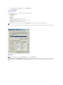
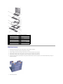
1
Dell™ Inspiron™ 4100
A Tour of Your Computer
Conserving Power
System Specifications
Solving Problems
Using the Dell™ Diagnostics
System Setup Program
Ports and Connector Pin-Outs
Removing and Replacing Parts
Hints, Notices, and Cautions
HINT: A HINT indicates important information that helps you make better use of your computer.
NOTICE: A NOTICE indicates either potential damage to hardware or loss of data and tells you how to avoid the problem.
CAUTION: A CAUTION indicates a potential for property damage, personal injury, or death.
Abbreviations and Acronyms
For a complete list of abbreviations and acronyms, see the Tell Me How help file (click the Start button on the Microsoft® Windows® desktop, point to
Programs—> User's Guides, and click Tell Me How).
Information in this document is subject to change without notice.
© 2000–2001 Dell Computer Corporation. All rights reserved.
Reproduction in any manner whatsoever without the written permission of Dell Computer Corporation is strictly forbidden.
Trademarks used in this text: Dell, the DELL logo, Dell TravelLite, Inspiron, and AccessDirect are trademarks of Dell Computer Corporation; Intel and Pentium are registered
trademarks and Intel SpeedStep is a trademark of Intel Corporation; Microsoft, MS-DOS, and Windows are registered trademarks of Microsoft Corporation.
Other trademarks and trade names may be used in this document to refer to either the entities claiming the marks and names or their products. Dell Computer Corporation
disclaims any proprietary interest in trademarks and trade names other than its own.
This product incorporates copyright protection technology that is protected by method claims of certain U.S. patents and other intellectual property rights owned by Macrovision
Corporation and other rights owners. Use of this copyright protection technology must be authorized by Macrovision Corporation, and is intended for home and other limited
viewing uses only unless otherwise authorized by Macrovision Corporation. Reverse engineering or disassembly is prohibited.
December 2001 Rev. A01
Back to Contents Page
Using the Dell™ Diagnostics Dell™ Inspiron™ 4100
When to Use the Dell Diagnostics
Features of the Dell Diagnostics
Starting the Dell Diagnostics
Advanced Testing
Confirming the System Configuration Information
When to Use the Dell Diagnostics
Whenever a major component or device in your computer does not function properly, you may have a component failure. If you are experiencing a problem
with your computer, Dell recommends that you perform the checks in "Solving Problems" and run the Dell Diagnostics before you contact Dell for technical
assistance.
As long as the microprocessor and the display, keyboard, and CD or DVD drive are working, you can use the Dell Diagnostics. Running the Dell Diagnostics may
help you to resolve the problem yourself quickly without having to contact Dell for assistance.
If you are experienced with computers and know what component(s) you need to test, simply select the appropriate diagnostic test group(s) or subtest(s). If
you are unsure about how to begin diagnosing a problem, see "Starting the Dell Diagnostics" and "Advanced Testing."
Features of the Dell Diagnostics
The Dell Diagnostics helps you check your computer hardware without any additional equipment and without destroying any data. By using the diagnostics,
you can have confidence in your computer's operation. And if you find a problem you cannot solve by yourself, the diagnostic tests can provide you with
important information you will need when talking to Dell's service and support personnel. If you are experiencing a problem with your computer, Dell
recommends that you perform the checks in "Solving Problems" and run the Dell Diagnostics before you contact Dell for technical assistance.
NOTICE: Use the Dell Diagnostics to test only your Dell computer. Using this program with other computers may cause incorrect computer responses or
result in error messages.
The diagnostic test groups or subtests also have these helpful features:
l
Options that let you perform quick checks or extensive tests on one or all devices
l
An option that allows you to choose the number of times a test group or subtest is repeated
l
The ability to display test results or to save them in a file
l
Options to temporarily suspend testing if an error is detected, or to terminate testing when an adjustable error limit is reached
l
Extensive online Help screens that describe the tests and how to run them
l
Status messages that inform you whether test groups or subtests were completed successfully
l
Error messages that appear if any problems are detected
Starting the Dell Diagnostics
Before you can start the Dell Diagnostics, reset your boot sequence and boot from the Drivers and Utilities CD for your computer:
NOTE: You can only boot from a CD, CD-RW, or DVD drive installed as a fixed drive. You cannot boot from a drive installed in the modular bay.
1.
Turn off the computer.
2.
If the computer is docked (connected to a docking device), undock the computer.
3.
Ensure that the computer is connected to an electrical outlet.
4.
Turn on the computer.
5.
Press
6.
Press
7.
In the system setup program Boot menu, change the boot sequence so that the CD or DVD drive boots first. Then insert the Drivers and Utilities CD into
the drive.
8.
Save the settings and exit the system setup program.
to enter the system setup program as soon as the Dell logo screen appears, and before the Microsoft® Windows® logo screen appears.
to locate the page with the Boot menu, and make a note of the device currently set to boot first.
The computer restarts and runs the Dell Diagnostics.
9.
When you have completed running diagnostics, remove the Drivers and Utilities CD.
10.
When the computer restarts, press
as soon as the Dell logo screen appears, and before the Microsoft Windows logo screen appears.
11.
In the system setup program, press
12.
Reset the boot sequence so that the device noted in step 6 boots first.
13.
Press
14.
Remove the CD from the drive.
until you locate the page with the Boot menu.
to exit the system setup program and restart Microsoft Windows.
When you start the diagnostics, the Dell logo screen appears, followed by a message telling you that the diagnostics is loading. After the diagnostics loads,
the Diagnostics Menu appears.
To select an option from this menu, highlight the option and press
choose.
, or press the key that corresponds to the highlighted letter in the option you
Diagnostics Menu
Option
Function
Test All Devices
Performs extensive diagnostic tests or quick diagnostic tests on all devices.
Test One Device
Performs extensive diagnostic tests or quick diagnostic tests on one device after you select it from a list of device groups. After you
select Test One Device, press
for more information about a test.
Advanced Testing
Allows you to modify the parameters of a test and select a group of tests to perform. You can access online Help for more information
about Advanced Testing.
Information and
Results
Provides test results, test errors, version numbers of the subtests used by the Dell Diagnostics, and additional help on the Dell
Diagnostics.
Program Options Allows you to change the settings of the Dell Diagnostics.
Exit to MS-DOS
Exits to the MS-DOS® prompt.
For a quick check of your computer, select Quick Tests from the Test All Devices or Test One Device option. Quick Tests runs only the subtests that do not
require user interaction and that do not take a long time to run. Dell recommends that you choose Quick Tests first to increase the odds of tracing the source
of the problem quickly.
For a thorough check of your computer, select Extended Tests from the Test All Devices option.
To check a particular area of your computer, select Extended Tests from the Test One Device option, or select the Advanced Testing option to customize your
test(s).
Advanced Testing
When you select Advanced Testing from the Diagnostics Menu, the following screen appears, listing the diagnostic test device groups and devices of the
selected device group, and it allows you to select categories from a menu. Press the arrow keys or
to navigate the screen.
Advanced Testing Main Screen
HINT: The test groups reflect the configuration of your computer.
Information in the Advanced Testing screen is presented as follows:
l
On the left side of the screen, the Device Groups area lists the diagnostic test groups in the order they will run if you select All from the Run tests
menu category. Press the up- or down-arrow key to highlight a test device group.
l
On the right side of the screen, the Devices for Highlighted Group area lists the computer's currently detected hardware and some of the relevant
settings.
l
Two lines at the bottom of the screen make up the menu area (see "Advanced Testing Help Menu"). The first line lists the categories you can select;
press the left- or right-arrow key to highlight a menu category. The second line gives information about the category currently highlighted.
Advanced Testing Help Menu
For more information on using the Advanced Testing option:
1.
Press
.
2.
Highlight the Help category and press
, or press the key that corresponds to the highlighted letter in the category you choose.
Advanced Testing Help Categories
Help
Category
Description
Menu
Provides descriptions of the main menu screen area, the device groups, and the different diagnostic menus and commands and instructions on
how to use them.
Keys
Explains the functions of all the keystrokes that can be used in the Dell Diagnostics.
Device
group
Describes the test group that is presently highlighted in the Device Groups list on the main menu screen. It also provides reasoning for using
some tests.
Device
Describes the function and purpose of the highlighted device in the Device Groups list. For example, the following information appears when
you select the Device Help category for Diskette in the Device Groups list:
Diskette
Drive A
The diskette disk drive device reads and writes data to and from diskettes. Diskettes are flexible recording media, sometimes
contained in hard shells. Diskette recording capacities are small and access times are slow relative to hard disk drives, but
they provide a convenient means of storing and transferring data.
Test
Provides a thorough explanation of the test procedure of each highlighted test group subtest. An example of the Diskette subtest floppy drive
Seek Test is as follows:
Diskette
Drive A - floppy drive Seek Test
This test verifies the drive's ability to position its read/write heads. The test operates in two passes: first, seeking from the
beginning to ending cylinders inclusively, and second, seeking alternately from the beginning to ending cylinders with
convergence towards the middle.
Versions Lists the version numbers of the subtests that are used by the Dell Diagnostics.
Confirming the System Configuration Information
When you boot your computer from your Drivers and Utilities CD, the diagnostics checks your system configuration information and displays it in the Device
Groups area on the main menu screen.
The following sources supply this configuration information for the diagnostics:
l
The system configuration information settings (stored in NVRAM) that you selected while using the system setup program
l
Identification tests of the microprocessor, the video controller, the keyboard controller, and other key components
l
BIOS configuration information temporarily saved in RAM
Do not be concerned if the Device Groups area does not list the names of all the components or devices you know are part of your computer. For example,
you may not see a printer listed, although you know one is attached to your computer. Instead, the printer is listed as a parallel port. The computer
recognizes the parallel port as LPT1, which is an address that tells the computer where to send outgoing information and where to look for incoming
information. Because your printer is a parallel communications device, the computer recognizes the printer by its LPT1 address and identifies it as a parallel
port. You can test your printer connection in the Parallel Ports tests.
Back to Contents Page
Back to Contents Page
Ports and Connector Pin-Outs
Dell™ Inspiron™ 4100
Port Locations
Serial Connector
Parallel Connector
Docking Connector
PS/2 Connector
USB Connector
Video Connector
S-Video TV-Out Connector
Port Locations
1 air intake
6 PS/2 connector
2 serial connector
7 USB connector
3 parallel connector 8 video connector
4 docking connector 9 AC adapter connector
5 air vent
Serial Connector
Use the 9-pin serial connector to attach a serial device to the computer. The serial connector passes data in serial format (1 bit at a time over one line). This
connector supports a variety of devices, including a serial mouse, that require serial data transmission. If you reconfigure your hardware, you may need pin
number and signal information for the serial connector.
Pin
Signal I/O Definition
1
DCD
I
Data carrier detect
2
RXDA
I
Receive data
3
TXDA
O
Transmit data
4
DTR
O
Data terminal ready
5
GND
N/A
Signal ground
6
DSR
I
Data set ready
7
RTS
O
Request to send
8
CTS
I
Clear to send
9
RI
I
Ring indicator
N/A
Frame ground
Shell N/A
Parallel Connector
Use the 25-hole parallel connector to attach a parallel device to the computer. The parallel connector is used primarily for printers. The parallel connector
transmits data in parallel format, where 8 data bits (one byte) are sent simultaneously over eight separate lines.
The parallel connector can also be configured for compatibility with the PS/2 standard. Support for the EPP feature improves network adapter performance
(adapters connect to the computer's parallel connector and require the appropriate software drivers from the adapter's manufacturer).
If you reconfigure your hardware, you may need pin number and signal information for the parallel connector.
Pin
Signal I/O Definition
1
STB#
I/O
Strobe
2
D0
I/O
Printer data bit 0
3
PD1
I/O
Printer data bit 1
4
PD2
I/O
Printer data bit 2
5
PD3
I/O
Printer data bit 3
6
PD4
I/O
Printer data bit 4
7
PD5
I/O
Printer data bit 5
8
PD6
I/O
Printer data bit 6
9
PD7
I/O
Printer data bit 7
10
ACK#
I
Acknowledge
11
BUSY
I
Busy
12
PE
I
Paper end
13
SLCT
I
Select
14
AFD#
O
Automatic feed
15
ERR#
I
Error
16
INIT#
O
Initialize printer
17
SLIN#
O
Select in
18-25 N/A
N/A
Ground signal
Shell
N/A
Frame ground
N/A
Docking Connector
Use this connector to attach your computer to the optional docking device.
Pin Signal
Pin
Signal
Pin
1
STRB#/5V
51
HSYNC
101 VGA_GRN
Signal
Pin
151 GND
Signal
2
PD0
52
VSYNC
102 GND
152 CLK_SPCI
3
PD1
53
GND
103 VGA_RED
153 GND
4
PD2
54
DOCKED
104 GND
154 SAD0
5
PD3
55
USB_VD1+
105 VGA_BLU
155 SAD1
6
PD4
56
USB_VD1-
106 DOCK_SD/MODE 156 SAD2
7
PD5
57
GND
107 D_IRTX
157 SAD3
8
PD6
58
USB_VD2+
108 D_IRRX
158 SAD4
9
PD7
59
USB_VD2-
109 GND
159 SAD5
10
GND
60
DOCKOC1#
110 SPIRQB#
160 SAD6
11
DOC_SPKR
61
RUN_ON#
111 SPIRQC#
161 GND
12
DOCK_MIC
62
GND
112 DAT_DDC2
162 SAD7
13
DOCK_LINE
63
NC
113 CLK_DDC2
163 SAD8
14
DOCK_CDROM
64
DOCK_SCLK
114 SPAR
164 SC/BE0#
15
GND
65
DOCK_LRCK
115 SPME#
165 SAD9
16
M_SEN#
66
DOCK_MCLK
116 GND
166 SAD10
17
POWER_SW#
67
GND
117 SSERR#
167 SAD11
18
QPCIEN#
68
+12V
118 SPERR#
168 SAD12
19
S1.6M_EN#
69
AFD#
119 SLOCK#
169 GND
20
DFDD/LPT#
70
ERROR#
120 SSTOP#
170 SAD13
21
GND
71
ACK#
121 GND
171 SAD14
22
NC
72
GND
122 SDEVSEL#
172 SAD15
23
NC
73
INIT#
123 STRDY#
173 SAD16
24
D_ATCTLED
74
SLCT_IN#
124 SIRDY#
174 SC/BE1#
25
D_PWRLED
75
BUSY
125 SFRAME#
175 SC/BE2#
26
DOCK_PWR_SRC 76
PE
126 SCLKRUN#
176 GND
27
DOCK_PWR_SRC 77
SLCT
127 GND
177 SAD17
28
DOCK_PWR_SRC 78
GND
128 SGNTA#
178 SAD18
29
GND
79
DAT_SMB
129 SREQA#
179 SAD19
30
+5VDOCK
80
DCLK_SMB
130 SGNT0#
180 SAD20
31
+5VDOCK
81
SMB_INIT#
131 SREQ0#
181 SAD21
32
+5VDOCK
82
GND
132 SPCIRST#
182 GND
33
+5VDOCK
83
DAT_DOCSM1
133 SH1SEL#
183 SAD22
34
+5VDOCK
84
CLK_DOCKSM1 134 GND
184 SAD23
35
GND
85
DAT_DOCKBD
135 SWRPRT#
185 SAD24
36
DOCK_PWR_SRC 86
CLK_DOCKBD
136 SDSKCHG#/DRQ 186 SC/BE3#
37
DOCK_PWR_SRC 87
GND
137 SDIR#
187 SAD25
38
DOCK_PWR_SRC 88
R10
138 STRK0#
188 GND
39
DOCK_PWR_SRC 89
CTS0
139 SSTEP#
189 SAD26
40
GND
90
RTS0
140 SDRV1#
190 SAD27
41
DOCK_+DC_IN
91
DSR0
141 GND
191 SAD28
42
DOCK_+DC_IN
92
GND
142 SMRT1#
192 SAD29
43
DOCK_+DC_IN
93
DTR0
143 SWRDATA#
193 SAD30
44
DOCK_+DC_IN
94
TXD0#
144 SWGATE#
194 SAD31
45
DOCK_+DC_IN
95
RXD0#
145 SRDATA#
195 GND
46
DOCK_+DC_IN
96
DCD0
146 SINDEX#
196 NC
47
DOCK_+DC_IN
97
NC
147 GND
197 NC
48
DOCK_+DC_IN
98
+5VSUS
148 NC
198 NC
49
GND
99
NC
149 +5VALW
199 NC
50
LOW_PWR
100 NC
150 NC
200 GND
PS/2 Connector
Use the 6-hole, miniature DIN PS/2 connector to attach PS/2-compatible devices such as a mouse, keyboard, or external numeric keypad. If you reconfigure
your hardware, you may need pin number and signal information for the PS/2 connector.
Pin
Signal
1
EXK_MSDATA I/O
I/O Definition
External keyboard/keypad/mouse data
2
KBD_DATA
I
Keyboard data
3
GND
N/A
Signal ground
4
EXK_MSPWR
N/A
External keyboard/keypad/mouse supply voltage
5
EXK_MSCLK
I/O
External keyboard/keypad/mouse clock
6
KBD_CLK
I
Keyboard clock
N/A
Chassis ground
Shell N/A
USB Connector
Use the USB connector to attach one or more USB devices, such as a mouse, to the computer. USB is a peripheral standard that enables automatic detection
of USB-compliant peripheral devices.
Pin Signal
Definition
1
VCC
Cable power
2
– Data
N/A
3
+Data
N/A
4
Ground Cable ground
Video Connector
Use the 15-pin video connector to attach an external monitor to the computer. If the image does not appear on the monitor immediately, press
.
Pin
Signal
I/O Definition
1
RED
O
Red video
2
GREEN
O
Green video
3
BLUE
O
Blue video
4
DDC2_MONID2 I
Monitor detect ID2
5
GND
N/A
Signal ground
6
GND
N/A
Signal ground
7
GND
N/A
Signal ground
8
GND
N/A
Signal ground
9
CRTVCC
O
5-V power source for CRT
10
GND
N/A
Signal ground
11
M-SEN#
I
Digital monitor sense/monitor detect ID1
12
DDC_DATA
I
Monitor detect serial data
13
HSYNC
O
Horizontal synchronization
14
VSYNC
O
Vertical synchronization
15
DDC_CLK
1
Monitor Detect serial clock
N/A
Frame ground
Shell N/A
S-Video TV-Out Connector
Use this connector on the right side of the computer to connect your computer to a television.
S-Video
Composite Video
Pin Signal
Pin
Signal
1
GND
5
NC
2
GND
6
DCMPS-L
3
DLUMA-L 7
GND
4
DCRMA-L Back to Contents Page
Back to Contents Page
Conserving Power
Dell™ Inspiron™ 4100
Conservation Tips
Power Conservation Modes
Power Options Properties
Conservation Tips
l
You automatically conserve battery power each time you attach your computer to an electrical outlet. When the AC adapter is attached, the battery is
charged while the computer uses AC power. Your battery's life expectancy is largely determined by the number of times it is charged, so use an AC
power source to run the computer if one is available.
l
When the computer is using battery power, remove the PC Cards that you are not using.
l
When possible, attach your computer to an electrical outlet when you play CDs and DVDs. Playing a CD or DVD uses a lot of battery power.
l
Place the computer in standby mode or hibernate mode when you leave the computer unattended for long periods of time.
Power Conservation Modes
Standby Mode
Standby mode conserves power by turning off the display and the hard drive after a predetermined period of inactivity (a time-out). When you exit standby
mode, the desktop is restored to the same state that it was in before the computer entered standby mode.
To activate standby mode:
l
Click the Start button, click Shut down (Turn Off Computer in the Microsoft® Windows® XP Home Edition operating system), click Stand by, and then
click OK.
l
Press the power button or the power conservation key combination,
or
, that you can program via the Advanced tab.
HINT: You can use the Advanced tab to program the display-close option, the power button, and the power conservation key combination to activate
standby mode.
To exit standby mode, press the power button, or if you activated standby mode by closing the display, open (raise) the display.
Hibernate Mode
Hibernate mode conserves power by copying system data to a reserved area on the hard drive and then completely turning off the computer. When you exit
hibernate mode, the programs and files that were open before you activated hibernate mode are still open.
Your computer enters hibernate mode if the battery charge level becomes critically low, or if either the power button, the power conservation key combination,
, or the display-close option are programmed to activate hibernate mode in the Advanced tab of the Power Options Properties window.
HINT: Some PC Cards may not operate correctly after exiting hibernate mode. If you encounter problems with a PC Card, reinsert the card or restart
your computer.
To exit hibernate mode, press the power button. The computer may take a short time to exit hibernate mode. Pressing a key or touching the touch pad or
track stick does not bring the computer out of hibernate mode.
Hibernate mode requires a special file on your hard drive with enough disk space to store the contents of the computer memory. Dell creates an appropriately
sized hibernate mode file before shipping the computer to you.
Power Options Properties
To access the Windows Power Options Properties window:
Windows XP
1.
Click the Start button, and then click Control Panel.
2.
Click Performance and Maintenance.
3.
Click the Power Options icon.
Windows 2000
1.
Click the Start button, point to Settings, and then click Control Panel.
2.
Click the Power Options icon.
Power Schemes Tab
The Power schemes pull-down menu displays the selected preset power scheme:
l
Portable/Laptop (default)
l
Home/Office
l
Always On
l
Presentation (Windows XP and Windows 2000 only)
l
Minimal Power Management (Windows XP and Windows 2000 only)
l
Max Battery (Windows XP and Windows 2000 only)
HINT: Dell recommends that you continue to use the Portable/Laptop power scheme to maximize battery power conservation.
Each preset power scheme has different time-out settings for putting the computer into standby mode, turning off the display, and turning off the hard drive.
Alarms Tab
HINT: To enable audible alarms, click each Alarm Action button and select Sound alarm.
The Low battery alarm and Critical battery alarm settings alert you with a message when the battery charge falls below a certain percentage. When you
receive your computer, the Lower battery alarm and Critical battery alarm check boxes are selected. Dell recommends that you continue to use these
defaults.
Power Meter Tab
The Power Meter tab displays the current power source and amount of battery charge remaining.
Advanced Tab
The Advanced tab allows you to:
l
Set icon and standby password options.
l
Program the following functions:
¡
Activate standby mode.
¡
Activate hibernate mode.
¡
Shut down Windows and turn off the computer.
¡
No action (None).
HINT: If you are going to connect your computer to a docking device, click None when you program the display-close option. This setting ensures that
your computer does not enter standby mode or hibernate mode when you close (lower) the display.
To program these functions, click an option from the corresponding pull-down menu, and then click OK.
Hibernate Tab
The Hibernate tab lets you enable hibernate mode by clicking the Enable hibernate support check box.
HINT: Windows XP automatically handles fluctuations in microprocessor performance during power source changes. Therefore, Intel SpeedStep
technology is not included with computers running Windows XP.
Intel® SpeedStep™ Tab
If your computer has a Mobile Intel Pentium® III processor, the Power Options Properties window includes the Intel® SpeedStep™ tab.
To change the Intel SpeedStep options, click the Advanced button and then click one of the following options.
HINT: If you disable Intel SpeedStep, the processor operates at its minimum speed.
l
Disable Intel SpeedStep technology control.
l
Remove flag icon.
l
Disable audio notification when performance changes.
Click Apply to accept any changes, and then click OK to close the Intel SpeedStep technology window.
Back to Contents Page
Back to Contents Page
Removing and Replacing Parts
Dell™ Inspiron™ 4100
Preparing to Work Inside the Computer
Keyboard Assembly
Recommended Tools
Display Assembly
Screw Identification
Display Latch
System Components
Hinge Covers
Palm Rest Inserts
Palm Rest
Display Cover
Microprocessor Thermal Cooling Assembly
Hard Drive Assembly
Microprocessor Module
Adding a Daughter Card Modem
Flashing the BIOS
Module Bay Devices
Reserve Battery
Memory Module
System Speaker Assembly
Mini PCI Card Assembly
System Board Assembly
Preparing to Work Inside the Computer
NOTICE: Only a certified service technician should perform repairs on your computer. Damage due to servicing that is not authorized by Dell is not
covered by your warranty.
NOTICE: To avoid damaging the computer, perform the following steps before you begin working inside the computer.
1.
Make sure that the work surface is clean to prevent scratching the computer cover.
2.
Save any work in progress and exit all open programs.
3.
Turn off the computer and all attached devices.
HINT: Make sure the computer is turned off and not in suspend mode or hibernate mode. If you cannot shut down the computer using the computer
operating system, press and hold the power button for 4 seconds.
4.
Make sure the computer is undocked.
5.
Disconnect the computer from the electrical outlet.
6.
To avoid possible damage to the system board, wait 10 to 20 seconds and then disconnect any attached devices.
7.
Disconnect all other external cables from the computer.
8.
Remove any installed PC Cards or plastic blanks from the PC Card slot.
9.
Close the display and turn the computer upside down on a flat work surface.
NOTICE: To avoid damaging the system board, you must remove the main battery and secondary battery (if present) before you service the computer.
10.
Remove the primary battery from the battery bay and the secondary battery from the module bay, if a secondary battery is in use.
11.
Remove any device installed in the module bay.
12.
To dissipate any static electricity while you work, use a wrist grounding strap or periodically touch an unpainted metal surface.
13.
Handle components and cards with care. Do not touch the components or contacts on a card. Hold a card by it edges or by its metal mounting bracket.
Hold a component such as a microprocessor by its edges, not by its pins.
Recommended Tools
The procedures in this manual require the following tools:
l
#1 magnetized Phillips screwdriver
l
¼-inch flat-blade screwdriver
l
Small plastic scribe
l
Microprocessor extractor
l
Flash BIOS update program floppy disk or CD
1 back
2 right
3 front
4 left
Screw Identification
When you are removing and replacing components, photocopy the placemat as a tool to lay out and keep track of the screws. The placemat provides the
number of screws and their sizes.
NOTICE: When reinstalling a screw, you must use a screw of the correct diameter and length. Make sure that the screw is properly aligned with its
corresponding hole, and avoid over tightening.
Hard Drive Door:
Keyboard to
Bottom Case:
(1 each)
(5 each)
Display Bezel:
Hinge Bracket to Bottom Case:
(6 each)
(5 each)
Rubber screw covers (6 each)
Display Assembly to Top Cover: Display-Feed Flex Cable:
(5 each)
(4 each)
Palm Rest to
Bottom Case:
Hybrid Cooling Fan:
(2 each) (1 each)
(5 each) (3 each)
System Board to Bottom Case:
Modem to
System Board:
(10 each)
(2 each)
Display Latch:
(2 each) (2 each)
System Components
Exploded View
NOTICE: Only a certified service technician should perform repairs on your computer. Damage due to servicing that is not authorized by Dell is not
covered by your warranty.
NOTICE: Unless otherwise noted, each procedure in this manual assumes that a part can be replaced by performing the removal procedure in reverse
order.
1 top cover display assembly
9
2 center control cover
10 memory module cover
bottom case assembly
3 thermal cooling assembly
11 module bay device
4 hybrid cooling fan
12 main battery
5 microprocessor module
13 hard drive
6 system board
14 left speaker/antenna assembly
7 right speaker/antenna assembly 15 palm rest assembly
8 fan guard
16 keyboard
Palm Rest Inserts
1.
Save and close any open files, exit any open programs, and shut down the computer.
2.
If the computer is connected (docked) to a docking device, undock it.
3.
Keep the display open and tilt the computer back so that you can access the bottom of the computer.
4.
Slide and hold the latch release on the right side, and remove any device installed in the module bay.
5.
Slide and hold the latch release on the left side, and remove any battery installed in the battery bay.
6.
Locate the orange palm-rest removal buttons. Firmly press the buttons with the eraser end of a pencil (or a dull utensil smaller than your finger) to
release the palm rests.
7.
Remove the palm rests.
8.
To replace the palm rests, insert the tabs on the inside edge of the palm rest into the slots on the computer. Then press along the outside edges of the
palm rest until it snaps into place.
Repeat the process on each side.
Display Cover
1.
Slide your index fingers under the straight edge of the display cover until the cover pops out.
2.
Slide the display cover towards the back of the computer.
3.
Use your fingers to release the cover completely, and remove it.
4.
To replace the display cover, bend it slightly to insert the four tabs on the rounded edge of the cover into the slots on the top of the computer.
5.
Press the cover along the straight edge at the back of the computer until it snaps into place.
6.
Firmly press the Dell™ logo until it snaps into place. Press above both hinge covers to engage the final snaps. Hard Drive Assembly
Removing the Hard Drive
1.
Save and close any open files, exit any open programs, and shut down the computer.
NOTICE: Disconnect the computer and any attached devices from electrical outlets, and remove any installed batteries.
NOTICE: The hard drive is very sensitive to shock. Handle the hard drive by its edges (do not squeeze the top of the hard drive case), and avoid
dropping it.
NOTICE: Read "Preparing to Work Inside the Computer" before performing the following procedure.
NOTICE: To prevent data loss, turn off your computer before removing the hard drive. Do not remove the hard drive while the computer is running, in
standby mode, or in hibernate mode.
CAUTION: If you remove the hard drive from the computer when the drive is hot, do not touch the metal housing of the hard drive.
2.
Ground yourself by touching a metal connector on the back of the computer.
3.
Turn the computer over. Remove the M3 x 5-mm screw from the hard drive door.
1 bottom of computer
2 M3 x 5-mm screw
3 hard drive door
4.
Lift up the hard drive door until you hear a click.
5.
Slide the hard drive out of the computer.
Replacing the Hard Drive
NOTICE: Use firm and even pressure to slide the hard drive into place. If you force the hard drive into place using excessive force, you may damage the
connector.
1.
Lift up the hard drive door until you hear a click. Push the hard drive into the drive bay until it is fully seated in the bay.
2.
Press the hard drive door down.
3.
Replace the M3 x 5-mm screw in the hard drive door.
Adding a Daughter Card Modem
If you ordered the optional modem at the same time that you ordered your computer, Dell has already installed the modem for you.
1.
Make sure that the work surface is flat and clean to prevent scratching the computer cover.
2.
Save and close any open files, exit any open programs, and shut down the computer.
3.
Disconnect the computer from the electrical outlet.
4.
Wait 10 to 20 seconds and then disconnect any attached devices.
5.
Remove any installed PC Cards, batteries, and devices.
6.
To ground yourself, periodically touch an unpainted metal surface on the back of the computer while you work.
7.
Handle components and cards by their edges, and avoid touching pins and contacts.
8.
Turn the computer over, and remove the screws from the modem cover.
9.
Place your finger under the cover at the indentation, and lift and slide the cover open.
10.
If a modem is not already installed, go to step 11. If you are replacing a modem, remove the existing modem:
a.
Remove the screw(s) that secure the modem to the system board, and set them aside.
b.
Pull straight up on the attached pull-tab to lift the modem out of its connector on the system board, and disconnect the modem cable.
1 pull-tab
2 modem cable connector
3 modem cable
11.
Connect the modem cable to the modem.
NOTICE: The cable connectors are keyed for correct insertion; do not force the connections.
12.
Align the modem with the screw hole(s) and press the modem into the connector on the system board.
13.
Install the screw(s) to secure the modem to the system board.
14.
Replace the modem cover.
Module Bay Devices
1.
Save and close any open files, exit any open programs, and shut down the computer.
2.
If the computer is connected (docked) to a docking device, undock it.
3.
Close the display and turn the computer over.
4.
Slide and hold the latch release, and pull the device out of the module bay.
NOTICE: To prevent damage to devices, place them in a travel case when they are not inserted in the computer. Store devices in a dry, safe place, and
avoid pressing down on them or placing heavy objects on top of them.
5.
To replace, insert the new device into the bay, and push it until you hear a click.
Memory Module
Removing the Memory Module Cover
NOTICE: Disconnect the computer and any attached devices from electrical outlets, and remove any installed batteries.
NOTICE: To avoid ESD, ground yourself by using a wrist grounding strap or by touching an unpainted metal surface on the computer.
NOTICE: Read "Preparing to Work Inside the Computer" before performing the following procedure.
1.
Turn the computer over, and use a flat-blade screwdriver to release the two captive screws from the memory module cover.
2.
Remove the M2.5 x 12-mm screw labeled "circle K."
3.
Place your finger under the cover at the indentation and lift and slide the cover open.
1 M2.5 x 12-mm screw (1)
2 captive screws (2)
Removing the Memory Modules
NOTICE: Disconnect the computer and any attached devices from electrical outlets, and remove any installed batteries.
NOTICE: To avoid ESD, ground yourself by using a wrist grounding strap or by touching an unpainted metal surface on the computer.
NOTICE: Read "Preparing to Work Inside the Computer" before performing the following procedure.
1.
Remove the memory module cover.
NOTICE: To prevent damage to the memory module connector, do not use tools to spread the inner metal tabs that secure the memory module.
2.
Use your fingertips to carefully spread apart the inner tabs on each end of the memory module socket.
The module should pop up.
1 JDIM 1
2 JDIM 2
3 memory module sockets (2)
4 inner tabs (2 per socket)
3.
Lift the memory module out of its socket.
Replacing the Memory Modules
1.
If you only have one memory module, install it in the connector labeled "JDIM1" on the system board. Install a second memory module in the connector
labeled "JDIM2."
HINT: Memory modules are keyed, or designed to fit into their sockets, in only one direction.
NOTICE: The memory module must be inserted at a 45-degree angle to avoid damaging the connector.
2.
Align the notch in the memory module with the slot in the center of the socket.
3.
Slide the edge connector of the module firmly into the socket at a 45- degree angle, and rotate the module down until you hear a click. If you do not
hear the click, remove the module and reinstall it.
4.
Replace the cover and tighten the two captive screws.
Mini PCI Card Assembly
You must remove the Mini PCI card before the system board can be removed.
Removing the Mini PCI Card
NOTICE: Disconnect the computer and any attached devices from electrical outlets, and remove any installed batteries.
NOTICE: To avoid ESD, ground yourself by using a wrist grounding strap or by touching an unpainted metal surface on the computer.
NOTICE: Read "Preparing to Work Inside the Computer" before performing the following procedure.
1.
Remove the memory module cover.
2.
Disconnect the Mini PCI card from the antenna cables.
3.
To release a Mini PCI card from its socket, spread apart the metal securing tabs until the card pops up slightly.
4.
Lift the Mini PCI card out of its connector.
1 antenna connectors on card (2)
2 antenna cables (2)
Replacing the Mini PCI Card
1.
Align the Mini PCI card with the socket at a 45-degree angle, and press the Mini PCI card into the socket.
NOTICE: The connectors are keyed for correct insertion; do not force the connections.
2.
Lower the Mini PCI card toward the inner tabs to approximately a
20-degree angle.
3.
Continue lowering the Mini PCI card until it snaps into the inner tabs of the socket.
4.
Attach the antenna cables to the Mini PCI card.
5.
Replace the cover and tighten the two captive screws.
Keyboard Assembly
Removing the Keyboard
NOTICE: Disconnect the computer and any attached devices from electrical outlets, and remove any installed batteries.
NOTICE: To avoid ESD, ground yourself by using a wrist grounding strap or by touching an unpainted metal surface on the computer.
NOTICE: Read "Preparing to Work Inside the Computer" before performing the following procedure.
1.
Remove the hard drive.
2.
Turn the computer over, and remove the five M2.5 x 12-mm screws labeled "circle K."
1 M2.5 x 12-mm screws (5)
3.
Turn the computer over and open the display.
NOTICE: The key caps on the keyboard are fragile, easily dislodged, and time-consuming to replace. Be careful when removing and handling the
keyboard.
4.
Remove the center control cover:
a.
Use a small, flat-blade screwdriver or plastic scribe to lift the right edge of the center control cover and pry it loose from the bottom case.
b.
Lift the center control cover up and away from the bottom case.
5.
To release the keyboard from the palm rest, use a small, flat-blade screwdriver or plastic scribe to pull up on the scalloped edge of the blank key on the
keyboard.
1 keyboard
2 track stick
3 scalloped edge of blank key
4 palm rest
6.
Lift the keyboard straight up until it clears the keyboard boss support in the bottom case.
7.
Rotate the keyboard forward toward the front of the computer.
8.
Rest the key face of the keyboard on the palm rest.
NOTICE: Do not pull on the keyboard flex and track stick cables.
9.
Pull up on the keyboard connector to disconnect it from the interface connector on the system board.
1 boss support (5)
2 track stick cable
3 keyboard flex cable
4 keyboard connector
5 orientation label
10.
Remove the keyboard from the bottom case.
Replacing the Keyboard
1.
Place the keyboard on the palm rest at the front of the computer with the keys face down and the connector toward the back of the computer.
NOTICE: To avoid damage to the connector pins, press the keyboard connector evenly into the interface connector on the system board, and do not
reverse the keyboard connector.
2.
Connect the keyboard connector to the interface connector on the system board.
The keyboard connector may have a label on it that shows the correct orientation of the keyboard connector to the system-board interface connector.
3.
Carefully turn the keyboard over. Align the keyboard boss support, fit the left side of the keyboard into place, and then snap the right side of the
keyboard into place.
NOTICE: Position the keyboard flex and track stick cables so that they are not pinched when you replace the keyboard in the bottom case.
4.
Check that the keyboard is correctly installed. The keys should be flush with the left and right surfaces of the palm rest.
5.
Replace the center control cover, close the display assembly, and turn the computer over.
6.
Reinstall the five M2.5 x 12-mm screws in the holes labeled "circle K."
Display Assembly
NOTICE: You must remove the display assembly before you remove the palm rest.
NOTICE: Disconnect the computer and any attached devices from electrical outlets, and remove any installed batteries.
NOTICE: To avoid ESD, ground yourself by using a wrist grounding strap or by touching an unpainted metal surface on the computer.
NOTICE: Read "Preparing to Work Inside the Computer" before performing the following procedure.
1 M2 x 3-mm screws (4)
2 top cover
3 center control cover
4 M2.5 x 5-mm screws (5)
5 bottom case
6 EMI shield bracket
1.
Remove the hard drive.
2.
Remove the center control cover.
3.
Remove the keyboard.
4.
Close the display.
5.
From the back of the computer, remove the five M2.5 x 5-mm screws labeled "circle D."
6.
Open the display assembly approximately 180 degrees and support the display assembly so that it does not open past this position.
7.
Remove the two M2 x 3-mm screws on the EMI shield bracket, which is attached to the display-feed flex cable.
8.
Remove the two M2 x 3-mm screws that secure the display-feed flex cable to the system board.
NOTICE: When reconnecting the display-feed flex cable connector to the system board, push down on the top left and right ends of the connector.
Pressing on the center of the connector may damage resistors and compromise EMI protection in the computer.
1 M2 x 3-mm screws (2)
9.
10.
Pull up on the pull-tab that is attached to the display-feed flex cable connector to remove the tab from the interface connector on the system board.
Lift the display assembly up and out of the bottom case.
1 rubber screw covers (6) 5 M2 x 4-mm screws (5)
2 M2.5 x 5-mm screws (4) 6 display-feed flex cable
3 display bezel
7 flex-cable retention bracket
4 top cover
8 display panel
Removing the 14.1-Inch Display Bezel
NOTICE: Disconnect the computer and any attached devices from electrical outlets, and remove any installed batteries.
NOTICE: To avoid ESD, ground yourself by using a wrist grounding strap or by touching an unpainted metal surface on the computer.
NOTICE: Read "Preparing to Work Inside the Computer" before performing the following procedure.
1.
Remove the hard drive.
2.
Remove the display assembly.
3.
Use a plastic scribe to pry the six rubber screw covers out of the screw holes located on the front of the bezel.
4.
Remove the six M2.5 x 5-mm screws located on the front of the bezel.
NOTICE: Carefully separate the bezel from the top cover to avoid damage to the bezel.
5.
Starting at the bottom of the display panel (by the DELL™ logo), use your fingers to separate the bezel from the top cover by lifting up the inside of the bezel while pushing in on the outside.
Removing the 14.1-Inch Display Panel
NOTICE: Disconnect the computer and any attached devices from electrical outlets, and remove any installed batteries.
NOTICE: To avoid ESD, ground yourself by using a wrist grounding strap or by touching an unpainted metal surface on the computer.
NOTICE: Read "Preparing to Work Inside the Computer" before performing the following procedure.
1.
Remove the hard drive.
2.
Remove the display assembly.
3.
Remove the display bezel.
4.
Remove the hinge covers.
5.
Remove the two M2 x 4-mm screws on the left side of the display panel and the two M2 x 4-mm screws on the right side of the display panel.
HINT: If you have a Hitachi display panel, remove the two M2 x 4- mm screws from the center of the left side of the display panel.
6.
Remove the M2 x 4-mm screw that secures the display-feed flex cable to the display assembly through the black plastic flex-cable retention bracket.
7.
Lift from the top and rotate the display panel out of the top cover.
8.
Disconnect the bottom flex-cable connector from the inverter connector by pulling straight up on the attached pull tab.
1 display panel connector
2 top flex-cable connector
3 pull tab
4 bottom flex cable connector
5 inverter connector
9.
10.
Remove the tape that secures the display panel connector and the tape that secures the middle of the display-feed flex cable to the display panel.
Pull the top flex-cable connector down and away to remove it from the display panel connector.
Replacing the 14.1-Inch Display Panel
1.
Reconnect the top flex-cable connector to the display panel connector.
2.
Reconnect the bottom flex-cable connector to the inverter connector.
3.
Replace the tape that secures the display panel connector and the tape that secures the middle of the display-feed flex cable to the display panel.
4.
Place the bottom edge of the display panel in the bottom of the top cover and elevate the top of the panel with your hand.
5.
Lay the display panel in the top cover.
Reinstall the five M2 x 4-mm screws that secure the display panel to the top cover.
Display Latch
NOTICE: Disconnect the computer and any attached devices from electrical outlets, and remove any installed batteries.
NOTICE: To avoid ESD, ground yourself by using a wrist grounding strap or by touching an unpainted metal surface on the computer.
Removing the Display Latch
1.
Remove the hard drive.
2.
Remove the display assembly.
3.
Remove the display bezel.
4.
Remove the two M2.5 x 5-mm screws and the two M1.7 x 3.5-mm screws that secure the display latch and bracket to the top cover.
5.
Lift the display latch and bracket up and out of the top cover.
1 M1.7 x 3.5-mm screws (2)
2 M2.5 x 5-mm screws (2)
3 display latch
4 bracket
Replacing the Display Latch
1.
On 14.1-inch XGA panels, place the display latch on top of its screw holes, and then place the bracket on top of the display latch, aligning the bracket
and display latch screw holes.
On 14.1-inch SXGA+ and UXGA panels, align the screw holes and place the display latch and attached bracket in the top cover.
2.
Replace the two M2.5 x 5-mm screws and the two M1.7 x 3.5-mm screws that secure the display latch and bracket to the top cover.
Hinge Covers
Removing the Hinge Covers
1.
Remove the display assembly.
2.
Rotate the hinges forward at an angle of approximately 90 degrees to the front of the display assembly.
3.
To remove the hinge covers, slide them off the hinges.
Replacing the Hinge Covers
1.
Attach the display assembly to the bottom case.
2.
Close the display assembly.
3.
Snap the hinge covers in place over the hinges.
HINT: The right plastic hinge cover label includes an "R," and the left plastic hinge cover label includes an "L." The hinge cover labels face the back of the
computer.
1 right hinge cover
2 left hinge cover
Palm Rest
NOTICE: Disconnect the computer and any attached devices from electrical outlets, and remove any installed batteries.
NOTICE: To avoid ESD, ground yourself by using a wrist grounding strap or by touching an unpainted metal surface on the computer.
NOTICE: Read "Preparing to Work Inside the Computer" before performing the following procedure.
1.
Remove the hard drive.
2.
Remove the keyboard.
NOTICE: You must remove the display assembly before you remove the palm rest; the display hinges pass through the back of the palm rest.
3.
Remove the display assembly and hinge covers.
4.
Turn the computer over and remove the three M2.5 x 12-mm screws labeled "circle P."
1 M2.5 x 12-mm screws (3)
2 M2 x 3-mm screws (2)
3 hard-drive bay door
5.
Remove the two M2 x 3-mm screws that are located in the hard-drive bay door labeled "circle P."
6.
Turn the computer over, and remove the three M2 x 3-mm screws that secure the palm rest to the bottom case:
7.
a.
Remove the two M2 x 3-mm screws that are located on the back edge of the bottom case, underneath the display assembly.
b.
Remove the M2 x 3-mm screw located underneath the keyboard, on the right side of the bottom case, next to the microprocessor thermal cooling
assembly.
Pull up on the pull-tab that is attached to the palm-rest flex cable connector to remove it from the interface connector on the system board.
1 M2 x 3-mm screws (3)
2 palm rest
3 palm-rest flex cable
4 bottom case
5 back center of the palm rest
6 touch pad connector
NOTICE: Carefully separate the palm rest from the bottom case to avoid damage to the palm rest.
8.
Starting at the back center of the palm rest, use your fingers to separate the palm rest from the bottom case by lifting up the inside of the palm rest
while pushing in on the outside.
1 M2.5 x 12-mm screws (3)
2 M2 x 3-mm screws (2)
Microprocessor Thermal Cooling Assembly
NOTICE: Disconnect the computer and any attached devices from electrical outlets, and remove any installed batteries.
NOTICE: To avoid ESD, ground yourself by using a wrist grounding strap or by touching an unpainted metal surface on the computer.
NOTICE: Read "Preparing to Work Inside the Computer" before performing the following procedure.
1.
Remove the hard drive.
2.
Remove the keyboard.
3.
Loosen the four captive screws that secure the microprocessor thermal cooling assembly to the system board.
1 microprocessor thermal cooling assembly
2 captive screws (4)
3 right side
4.
Lift the microprocessor thermal cooling assembly up and out of the system board.
Replacing the Microprocessor Thermal Cooling Assembly
1.
Place the right side of the microprocessor thermal cooling assembly under the palm rest and lower the assembly onto the system board.
2.
Tighten the four captive screws, labeled 1 through 4, in consecutive order.
Microprocessor Module
Removing the Microprocessor Module
NOTICE: Disconnect the computer and any attached devices from electrical outlets, and remove any installed batteries.
NOTICE: To avoid ESD, ground yourself by using a wrist grounding strap or by touching an unpainted metal surface on the computer.
NOTICE: Read "Preparing to Work Inside the Computer" before performing the following procedure.
NOTICE: Do not touch the processor die. Press and hold the microprocessor down on the substrate on which the die is mounted while turning the cam
screw to prevent intermittent contact between the cam screw and microprocessor.
NOTICE: To avoid damage to the microprocessor, hold the screwdriver so that it is perpendicular to the microprocessor when turning the cam screw.
1 screwdriver (perpendicular to microprocessor)
2 pin-1 corner
3 processor die (do not touch)
4 ZIF socket
5 ZIF-socket cam screw
1.
Remove the hard drive.
2.
Remove the keyboard.
NOTICE: To ensure maximum cooling for the microprocessor, do not touch the heat transfer areas on the microprocessor thermal cooling assembly. The
oils in your skin reduce the heat transfer capability of the thermal pads.
3.
Remove the microprocessor thermal cooling assembly.
NOTICE: When removing the microprocessor module, pull the module straight up. Be careful not to bend the pins on the microprocessor module.
4.
To loosen the ZIF socket, use a small, flat-blade screwdriver and rotate the ZIF-socket cam screw counter-clockwise until it comes to the cam stop.
The ZIF-socket cam screw secures the microprocessor to the system board. Take note of the arrow on the ZIF-socket cam screw.
5.
Use a microprocessor extraction tool to remove the microprocessor module.
Replacing the Microprocessor Module
NOTICE: Ensure that the cam lock is in the fully open position before seating the microprocessor module. Seating the microprocessor module properly in
the ZIF socket does not require force.
NOTICE: A microprocessor module that is not properly seated can result in an intermittent connection, or permanent damage to the microprocessor and
ZIF socket.
1.
Align the pin-1 corner of the microprocessor module with the pin-1 corner of the ZIF socket, and insert the microprocessor module.
HINT: The pin-1 corner of the microprocessor module has a triangle that aligns with the triangle on the pin-1 corner of the ZIF socket.
NOTICE: You must position the microprocessor module correctly in the ZIF socket to avoid permanent damage to the module and the socket.
When the microprocessor module is correctly seated, all four corners are aligned at the same height. If one or more corners of the module are higher
than the others, the module is not seated correctly.
NOTICE: Hold the microprocessor down while turning the cam screw to prevent intermittent contact between the cam screw and microprocessor (see
"Removing the Microprocessor Module").
2.
Tighten the ZIF socket by turning the cam screw clockwise to secure the microprocessor module to the system board.
3.
Update the BIOS using a flash BIOS update program floppy disk or CD. For instructions on how to flash the BIOS, see "Flashing the BIOS."
Flashing the BIOS
To update the BIOS:
1.
Make sure that the AC adapter is plugged in and that the main battery is installed properly.
2.
Turn on the computer. The following error message appears:
System hardware failures: #0010
Strike the F1 key to shutdown
3.
Instead of pressing
, insert the flash BIOS update floppy disk or
CD into the appropriate drive and press
, and then press
. The computer displays the following message on the screen:
Failure override
Processor update failure. Reload current BIOS
Strike the F1 key to continue, F2 to run the setup utility.
4.
Press
. The computer continues to boot and updates the new BIOS.
5.
Press
to enter the system setup program and reset the boot sequence with the appropriate drive, if required.
6.
Press
to exit the system setup program.
7.
Remove the flash BIOS update floppy disk or CD from the drive and restart the computer.
Reserve Battery
Removing the Reserve Battery
NOTICE: The reserve battery provides power to the computer's RTC and NVRAM when the computer is turned off. Removing the battery causes the
computer to lose the date and time information as well as all user-specified parameters in the BIOS. If possible, make a copy of this information before
you remove the reserve battery.
NOTICE: Disconnect the computer and any attached devices from electrical outlets, and remove any installed batteries.
NOTICE: To avoid ESD, ground yourself by using a wrist grounding strap or by touching an unpainted metal surface on the computer.
NOTICE: Read "Preparing to Work Inside the Computer" before performing the following procedure.
1.
Remove the hard drive.
2.
Remove the keyboard.
3.
Disconnect the reserve battery cable from the system board connector.
4.
Pry the reserve battery free from the system board. The reserve battery is attached to the system board with a piece of adhesive tape.
5.
Remove any remnants of the adhesive tape from the system board.
1 reserve battery
2 speaker connector
3 system board connector
4 reserve battery cable
Replacing the Reserve Battery
1.
Connect the reserve battery cable to the system board connector.
2.
Position the reserve battery above the speaker connector on the system board.
3.
Update the BIOS using a flash BIOS update program floppy disk or CD. For instructions on how to flash the BIOS, see "Flashing the BIOS."
System Speaker Assembly
Removing the Speaker Assemblies
NOTICE: Disconnect the computer and any attached devices from electrical outlets, and remove any installed batteries.
NOTICE: To avoid ESD, ground yourself by using a wrist grounding strap or by touching an unpainted metal surface on the computer.
NOTICE: Read "Preparing to Work Inside the Computer" before performing the following procedure.
The speakers are located on the front left and right sides of the bottom case. Each speaker assembly is marked with a left or right label. Take note of the
speaker and antenna wire routing so that you can replace them properly under their routing clips.
1 right speaker
2 palm-rest screw post
3 bottom case holders (2)
4 left speaker
1 antenna cable
6 antenna cable
2 in-line connector
7 right speaker holder
3 left speaker
8 mounting ring
4 mounting ring
9 right speaker
5 left speaker holder 1.
Remove the hard drive.
2.
Remove the keyboard.
3.
Remove the display assembly.
4.
Remove the palm rest.
5.
Disconnect the speaker interface cable connectors.
NOTICE: Do not pull the antenna wire when removing the speaker.
NOTICE: Handle the speaker assemblies and speakers with care to avoid damaging the speaker cones.
6.
Remove the speaker assemblies by pulling them straight up and out of the bottom case.
HINT: The left speaker has an in-line connector, and its antenna cable is longer than the antenna cable of the right speaker.
Replacing the Speaker Assemblies
1.
Place the mounting ring over the front palm-rest screw post.
NOTICE: Make sure the speaker wires are under their routing clips. Route the left speaker wire properly between the battery bay and hard drive area.
2.
Slide the speaker assembly down in to the bottom case.
HINT: Speakers face out in the bottom case holders.
System Board Assembly
Removing the System Board
The system board's BIOS chip contains the service tag sequence, which is also visible on a barcode label on the bottom of the computer. The replacement kit
for the system board includes a CD that provides a utility for transferring the service tag sequence to the replacement system board.
NOTICE: Disconnect the computer and any attached devices from electrical outlets, and remove any installed batteries.
NOTICE: To avoid ESD, ground yourself by using a wrist grounding strap or by touching an unpainted metal surface on the computer.
NOTICE: Read "Preparing to Work Inside the Computer" before performing the following procedure.
1.
Remove the hard drive.
2.
Remove the keyboard.
3.
Remove the display assembly.
4.
Remove the palm rest.
5.
Remove the microprocessor thermal cooling assembly.
6.
Remove the microprocessor.
7.
Remove the modem, memory modules, and Mini PCI card.
8.
Turn the computer over, and remove the six M2.5 x 5-mm screws labeled "circle B" that secure the system board to the bottom case.
9.
Remove the three M2.5 x 5-mm screws labeled "circle B" that secure the fan guard to the bottom case.
1 fan guard
2 M2.5 x 5-mm screws (9)
10.
Turn the computer over and remove the M2.5 x 5-mm screw, which is labeled "circle B" with an arrow on the front center of the system board by the
battery connector.
1 M2.5 x. 5-mm screw (1)
11.
Remove the speakers from the bottom case.
12.
Pull the right side of the bottom case, next to the external headphone and microphone connectors, away from the system board as you simultaneously
lift the front of the system board out and away from the bottom case.
Replacing the System Board
1.
Install the microprocessor on the replacement system board.
2.
Connect the right and left speakers to the replacement system board.
3.
Install the replacement system board:
4.
a.
Insert the external microphone and headphone connectors through the bottom case.
b.
Replace the six M2.5 x 5-mm screws, starting on the right side of the bottom case.
c.
Replace the fan guard, inserting the tab into the bottom case, and replace the three M2.5 x 5-mm screws. Replacing the screw opposite the tab
first makes it easier to insert and replace the other two screws.
Replace the modem, the speaker assemblies, and the microprocessor thermal cooling assembly that you removed from the old system board.
HINT: Be sure to route cables so that they will not be crimped or pinched when the complete assembly is put back together.
5.
Replace the palm rest, the keyboard, the display assembly, and the hard drive.
6.
Replace the module bay devices and any PC Cards or plastic blanks in the PC Card slot.
7.
Insert the floppy disk or CD that accompanied the replacement system board into the appropriate drive, and turn on the computer. Follow the
instructions on the screen.
HINT: After replacing the system board, be sure to enter the computer service tag sequence into the BIOS of the replacement system board.
Module Latch Assemblies
Removing the Battery and Module Bay Latches
NOTICE: Disconnect the computer and any attached devices from electrical outlets, and remove any installed batteries.
NOTICE: To avoid ESD, ground yourself by using a wrist grounding strap or by touching an unpainted metal surface on the computer.
NOTICE: Read "Preparing to Work Inside the Computer" before performing the following procedure.
1.
Remove the hard drive.
2.
Remove the keyboard.
3.
Remove the display assembly.
4.
Remove the palm rest.
5.
Remove the system board.
6.
Remove the latch button by using a plastic scribe to push on the snap tabs until the latch button is released from the bottom case.
To prevent the latch assembly from coming loose, apply pressure to the latch and spring while removing the latch button. If the latch assembly does
come loose from the case:
a.
Slide the spring onto the slider on the latch, and reinstall the latch into the holding features on the inside of the bottom case.
b.
Ensure that the slider is inserted into the hole, that the side of the latch with the two bumps is facing the back of the case, and that the side with
the wear rib is facing the front of the case.
HINT: The latch will not function properly if the slider is oriented incorrectly.
1 bumps (2 per latch) 5 latch buttons (2)
2 slider
6 snap tabs (2 per latch button)
3 spring
7 wear rib
4 bottom case
Replacing the Battery and Module Bay Latches
1.
Snap in the new latch button from behind the bottom case, making certain that the snap tabs are fully engaged in the latch.
To prevent the latch assembly from coming loose, apply pressure to the latch and spring while replacing the latch button.
2.
Ensure that the newly installed latch moves smoothly and freely when pushed and released.
Back to Contents Page
Back to Contents Page
System Setup Program
Dell™ Inspiron™ 4100
Overview
Viewing the System Setup Screens
System Setup Screens
Commonly Used Options
Overview
HINT: Your operating system may automatically configure most of the options available in the system setup program, thus overriding options that you
set through the system setup program. (An exception is the External Hot Key option, which you can disable or enable only through the system setup
program.) For more information on configuring features for your operating system, see your Microsoft® Windows Help or Windows Help and Support
Center.
You can use the system setup program as follows:
l
To set or change user-selectable features—for example, your password
l
To verify information about your computer's current configuration, such as the amount of system memory
After you set up your computer, run the system setup program to familiarize yourself with your system configuration information and optional settings. Dell
recommends that you write down the information for future reference.
NOTICE: Unless you are an expert computer user or are directed to do so by Dell technical support, do not change the settings for this program.
Certain changes might make your computer work incorrectly.
Viewing the System Setup Screens
1.
2.
Turn on (or restart) your computer.
When the Dell™ logo appears, press immediately.
If you wait too long and the Windows® logo appears, continue to wait until you see the Windows desktop. Then shut down your computer and try
again.
Depending on your computer, you may also be able to enter the system setup program by pressing the
the computer is running.
keyboard shortcut at any time while
System Setup Screens
The system setup screens display the current setup information and settings for your computer. Each screen is laid out with the system setup options listed at
the left. To the right of each option is a field that displays the setting or value for that option. You can change settings that appear as white type on the
screen. Options or values that you cannot change (because they are determined by the computer) appear less bright.
A box in the upper-right corner of the screen displays help information for the currently highlighted option; a box in the lower-right corner displays information
about the computer. System setup key functions are listed across the bottom of the screen.
The screens display such information as:
l
System configuration
l
Boot configuration and dock configuration settings
l
Basic device configuration settings
l
Battery charge status
l
Power management settings
l
System security and hard drive password settings
HINT: Certain options require that you reboot the computer for new settings to take effect.
Commonly Used Options
Changing the Boot Sequence
The boot sequence tells the computer where to look to find the software needed to start the operating system. To change the computer's boot sequence,
change the device settings in the Boot First Device, Boot Second Device, or Boot Third Device options.
Boot Sequence
Option
Description
Boot First Device
Tells the computer where to look first for the software it needs to start the operating system
Boot Second Device
Tells the computer where to look next if it cannot find the software on the drive identified in Boot First Device
Boot Third Device
Tells the computer where to look next if it cannot find the software on the drives identified in Boot First Device or Boot Second
Device
For a change in the boot sequence options to take effect, you must reboot your computer.
Changing Printer Modes
Set the Parallel Mode option according to the type of printer or device connected to the parallel port. To determine the correct mode to use, see the
documentation that came with the device.
Setting Parallel Mode to Disabled disables the parallel port and its assigned LPT address, freeing its interrupt for another device to use.
Changing COM Ports
Serial Port allows you to map the address of the serial port, or to disable the serial port and its assigned COM address, freeing that interrupt for another
device to use.
Enabling the Infrared Sensor
1.
Press
2.
Press the down-arrow key to highlight Disabled next to Infrared Data Port.
3.
and repeat to locate the Infrared Data Port option under the Basic Device Configuration heading of the system setup program.
Press the right-arrow key to highlight a COM port.
Ensure that the COM port that you highlight is different from the Serial Port COM port.
4.
Press the down-arrow key to highlight Fast IR or Slow IR.
Dell recommends that you use Fast IR. If the infrared device cannot communicate with your computer, turn off the computer and repeat this procedure
to change the setting to Slow IR.
5.
Press
to save the changes and exit the system setup program.
The Microsoft® Windows® operating system starts automatically.
6.
Follow the instructions on the screen while the infrared sensor driver is installing.
7.
At the end of the install process, click Yes to restart the computer.
8.
When your computer detects the presence of another activated infrared device, double-click the infrared icon that appears on the Windows taskbar.
HINT: If the infrared device cannot communicate with your computer, turn off the computer and repeat this procedure to change the system setup
program setting to Slow IR. If the infrared device still cannot communicate with your computer, contact the infrared device manufacturer.
The Infrared Monitor screen appears.
9.
10.
Click the Options tab and then click Enable Infrared Communication.
Click OK.
See the infrared device documentation for device setup instructions.
Back to Contents Page
Back to Contents Page
Solving Problems
Dell™ Inspiron™ 4100
Accessing Help Files
Network Problems
Power Problems
General Program Problems
Error Messages
E-Mail Problems
Video and Display Problems
If Your Computer Gets Wet
Sound and Speaker Problems
If You Drop or Damage Your Computer
Printer Problems
Resolving Other Technical Problems
Modem and Internet Connection Problems
Reinstalling Drivers and Utilities
Scanner Problems
Manually Reinstalling Drivers
Touch Pad or Mouse Problems
Resolving Software and Hardware Incompatibilities
External Keyboard Problems
Using System Restore
Unexpected Characters
Reinstalling Windows®
Drive Problems
Accessing Help Files
To access the Tell Me How help file Microsoft® Windows® XP
1.
2.
3.
Click the Start button, and then click Help and Support.
Click User and system guides, and then click User's guides.
Click Tell Me How.
Windows Millennium Edition (Me) and Windows 2000
1.
Click the Start button, point to Programs, point to User's Guides, and then click Tell Me How.
To access help in Windows XP
1.
2.
3.
4.
Click the Start button, and then click Help and Support.
Type a word or phrase that describes your problem, and then click the arrow icon.
Click the topic that describes your problem, and then click Display.
Follow the instructions shown on the screen.
To access help in Windows Me
1.
2.
3.
4.
Click the Start button, and then click Help.
Type a word or phrase that describes your problem in the Search box, and then click Go.
Click the topic that describes your problem, and then click Display.
Follow the instructions shown on the screen.
To access help in Windows 2000
1.
2.
3.
4.
5.
Click the Start button, and then click Help.
Click the Search tab.
Type a word or phrase that describes your problem, and then click List Topics.
Click the topic that describes your problem, and then click Display.
Follow the instructions shown on the screen.
Power Problems
HINT: See the Tell Me How help file for information on standby mode. See "Accessing Help Files."
Check the power light— When the power light is lit or blinking, the computer has power. If the power light is blinking, the computer is in
standby mode—press the power button to exit standby mode. If the light is off, press the power button to turn on the computer.
Charge the battery— The battery charge may be depleted.
1.
2.
3.
Reinstall the battery.
Use the AC adapter to connect the computer to an electrical outlet.
Turn on the computer.
Check the battery status light— If the battery status light flashes orange or is a steady orange, the battery charge is low or depleted.
Connect the computer to an electrical outlet.If the battery status light flashes green and orange, the battery is too hot to charge. Turn off
the computer, disconnect the computer from the electrical outlet, and then let the battery and computer cool to room temperature.If the
battery status light rapidly flashes orange, the battery may be defective. See "Contacting Dell" in the Dell Solutions Guide.
Test the electrical outlet— Ensure that the electrical outlet is working by testing it with another device, such as a lamp.
Check the AC adapter— Check the AC adapter cable connections. If the AC adapter has a light, ensure that the light is on.
Connect the computer directly to an electrical outlet— Bypass power protection devices, power strips, and the extension cable to verify
that the computer turns on.
Eliminate possible interference— Turn off nearby fans, fluorescent lights, halogen lamps, or other appliances.
Adjust the Power Properties— See the Tell Me How help file or search for the keyword standby in Windows Help. See "Accessing Help Files."
Reseat the memory modules— If your computer power light turns on but the display remains blank, reseat the memory modules. See
"Memory Module."
Error Messages
HINT: If the message is not listed, see the documentation for the operating system or the program that was running at the time the message
appeared.
The file being copied is too large for the destination drive— The file that you are trying to copy is too large to fit on the disk, or the disk is
too full. Try copying the file to a different disk or use a larger capacity disk.
A filename cannot contain any of the following characters: \ / : * ? " < > |— Do not use these characters in filenames.
Insert bootable media— The operating system is trying to boot to a nonbootable floppy disk or CD. Insert a bootable floppy disk or CD.
Non-system disk or disk error— A floppy disk is in the floppy drive. Remove the floppy disk and restart the computer.
Not enough memory or resources. Close some programs and try again— You have too many programs open. Close all windows and open
the program that you want to use.
Operating system not found— Reseat the hard drive.
A required .DLL file was not found— The program that you are trying to open is missing an essential file. To remove and then reinstall the
program:
Windows XP
1.
2.
3.
4.
5.
6.
Click the Start button.
Click Control Panel.
Click Add or Remove Programs.
Click the program you want to remove.
Click the Change or Remove Program icon.
See the program documentation for installation instructions.
Windows Me and Windows 2000
1.
2.
3.
4.
5.
Click the Start button, point to Settings, and then click Control Panel.
Double-click the Add/Remove Programs icon.
Click the program that you want to remove.
Click Add/Remove (click Change/Remove in Windows 2000) and follow the prompts on the screen.
See the program documentation for installation instructions.
x:\ is not accessible. The device is not ready— Insert a disk into the drive and try again.
Video and Display Problems
If the display is blank
HINT: If you are using a program that requires a higher resolution than your computer supports, Dell recommends that you attach an external monitor
to your computer.
Check the power light— When the power light is blinking, the computer has power.
l
l
l
If the power light is blinking, the computer is in standby mode—press the power button to exit standby mode.
If the power light is off, press the power button.
If the power light is on, your power management settings may have caused the display to turn off. Try pressing any key or move the
cursor to exit standby mode.
Check the battery— If you are using a battery to power your computer, the battery charge may be depleted. Connect the computer to an
electrical outlet using the AC adapter, and turn on the computer.
Test the electrical outlet— Ensure that the electrical outlet is working by testing it with another device, such as a lamp. If the device is
plugged into a surge protector, try plugging it directly into an electrical outlet.
Check the AC adapter— Check the AC adapter cable connections. If the AC adapter has a light, ensure that it is on.
Connect the computer directly to an electrical outlet— Bypass power protection devices, power strips, and the extension cable to verify
that the computer turns on.
Adjust the Power Properties— Search for the keyword standby in Windows Help. See "Accessing Help Files."
Switch the video image— If your computer is attached to an external monitor, press
to switch the video image to the display.
If the display is difficult to read
Adjust the brightness— Press
to increase the brightness, or press
to decrease the brightness.
Move the subwoofer away from the computer or monitor If your external speaker system includes a subwoofer, ensure that the
subwoofer is at least 60 cm (2 ft) away from the computer or external monitor.
Eliminate possible interference— Turn off nearby fans, fluorescent lights, halogen lamps, or other appliances.
Rotate the computer to face a different direction— Eliminate sunlight glare, which can cause poor picture quality.
Adjust the Windows display settings
Windows XP
1.
2.
3.
4.
Click the Start button, and then click Control Panel.
Click Appearance and Themes.
Click Display, and then click the Settings tab.
Try different settings for Screen resolution and Color quality.
Windows Me and Windows 2000
1.
2.
3.
Click the Start button, point to Settings, and then click Control Panel.
Double-click the Display icon, and then click the Settings tab.
Try different settings for Colors and Screen area.
See "Error Messages"— If an error message appears, see "Error Messages."
If only part of the display is readable
Connect an external monitor
1.
2.
Turn off your computer and connect an external monitor to the computer.
Turn on the computer and the monitor and adjust the monitor brightness and contrast controls.
If the external monitor works, the computer display or video controller may be defective. See "Contacting Dell" in the Dell Solutions Guide.
Sound and Speaker Problems
If you have a problem with integrated speakers
Adjust the Windows® volume control— Double-click the yellow speaker icon in the lower-right corner of your screen. Be sure that the
volume is turned up and that the sound is not muted. Adjust the volume, bass, or treble controls to eliminate distortion.
Adjust the volume using keyboard shortcuts— Press
to disable (mute) or reenable the integrated speakers.
Reinstall the sound (audio) driver— See "Reinstalling Drivers and Utilities."
If you have a problem with external speakers
HINT: The volume control in some MP3 players overrides the Windows volume setting. If you have been listening to MP3 songs, make sure that you did
not turn the player volume down or off.
Check the speaker cable connections— See the setup diagram supplied with the speakers.
Test the electrical outlet— Ensure that the electrical outlet is working by testing it with another device, such as a lamp. If the device is
plugged into a surge protector, try plugging it directly into an electrical outlet.
Ensure that the speakers are turned on— See the setup diagram supplied with the speakers.
Adjust the Windows volume control— Double-click the yellow speaker icon in the lower-right corner of your screen. Be sure that the volume
is turned up and that the sound is not muted. Adjust the volume, bass, or treble controls to eliminate distortion.
Test the speakers— Plug the speaker audio cable into the line-out connector on the computer. Ensure that the headphone volume control is
turned up. Play a music CD.
Run the speaker self-test— Some speaker systems have a self-test button on the subwoofer. See the speaker documentation for self-test
instructions.
Move the subwoofer away from the computer or monitor— If your external speaker system includes a subwoofer, ensure that the
subwoofer is at least 60 cm (2 ft) away from the computer or external monitor.
Eliminate possible interference— Turn off nearby fans, fluorescent lights, or halogen lamps to check for interference.
Reinstall the Sound (audio) driver— See "Reinstalling Drivers and Utilities."
Printer Problems
Check the printer cable connections— Ensure that the printer cable is properly connected to the computer (see "Connecting a Printer" in
the Dell Solutions Guide that came with your computer).
Test the electrical outlet— Ensure that the electrical outlet is working by testing it with another device, such as a lamp.
Ensure that the printer is turned on— See the documentation supplied with the printer.
Verify that Windows® recognizes the printer
1.
Click the Start button, point to Settings, and then click Printers.
If the printer is listed, right-click the printer icon, click Properties, and then select the Details tab.
2.
Ensure that the Print to the following port: option is set for your printer type:
l For a parallel printer: LPT1 (Printer Port)
l For a USB printer: USB
Reinstall the printer driver— See "Installing the Printer Driver" in the Dell Solutions Guide.
Modem and Internet Connection Problems
NOTICE: Connect the modem to an analog telephone wall jack only. Connecting the modem to a digital telephone network damages the modem.
NOTICE: Modem and network connectors look similar. Do not plug a telephone line into the network connector.
HINT: If you can connect to your Internet service provider (ISP), your modem is functioning properly. If you are sure that your modem is working
properly and you still experience problems, contact your ISP.
Check the telephone wall jack— Disconnect the telephone line from the modem and connect it to a telephone. Listen for a dial tone. Ensure
that you have touchtone telephone service. Try connecting the modem to a different telephone wall jack.
Connect the modem directly to the telephone wall jack— If you have other telephone devices sharing the line, such as an answering
machine, fax machine, surge protector, or line splitter, then bypass them and connect the modem directly to the telephone wall jack with the
telephone line.
Check the connection— Verify that the telephone line is connected to the modem.
Check the telephone line— Try using a different telephone line. If you are using a line that is 3 m (10 ft) or more in length, try a shorter one.
Irregular dial tone — If you have voice mail service, you may hear an irregular dial tone when you have messages. Contact your telephone
company for instructions on restoring a normal dial tone.
Turn off call waiting (catch-phone)— See your telephone directory for instructions on deactivating this feature. Then adjust the dial-up
networking connection properties:
1.
2.
3.
4.
5.
6.
7.
Click the Start button, point to Settings, and then click Control Panel.
Double-click the Modems icon.
In the Modems Properties window, click Dialing Properties.
Ensure that To disable call waiting, dial: is checked, and then select the proper code as listed in your telephone directory.
Click Apply and then click OK.
Close the Modems Properties window.
Close the Control Panel window.
Verify that the modem is communicating with Windows
Windows XP
1.
2.
3.
4.
5.
Click the Start button.
Click Control Panel.
Click Network and Internet Connections.
Click Internet Options.
Click Network Diagnostics and perform the connectivity test.
Windows Me
1.
2.
Click the Start button, point to Settings, and click Control Panel.
In the Control Panel window, double-click Modems.
If there are multiple entries for the same modem or modems listed that are not installed, delete the entries and restart the computer.
3.
4.
5.
Click the Diagnostics tab.
Click the COM port for your modem.
Click More Info to verify that the modem is communicating with Windows.
If all commands receive responses, the modem is operating properly.
Windows 2000
1.
2.
Click the Start button, point to Settings, and click Control Panel.
In the Control Panel window, double-click Phone and Modem Options.
If there are multiple entries for the same modem or modems listed that are not installed, delete the entries and restart the computer.
3.
4.
5.
6.
Click
Click
Click
Click
the
the
the
the
Modems tab.
COM port for your modem.
Properties button.
Diagnostics tab to verify that the modem is communicating with Windows.
If all commands receive responses, the modem is operating properly.
Scanner Problems
Check the power cable connection— Ensure that the scanner power cable is firmly connected to a working electrical power source and that
the scanner is turned on. If the device is plugged into a surge protector, try plugging it directly into an electrical outlet.
Check the scanner cable connection— Ensure that the scanner cable is firmly connected to the computer and to the scanner.
Unlock the scanner— Ensure that your scanner is unlocked if it has a locking tab or button.
Reinstall the scanner driver— See the scanner documentation for instructions.
Touch Pad or Mouse Problems
Check the touch pad settings— Click the Start button, point to Settings, click Control Panel, and then double-click the Mouse icon. Try
adjusting the settings.
Check the mouse cable— Shut down the computer. Disconnect the mouse cable and check it for damage. For PS/2 cables, check the cable
connector for bent or broken pins. Firmly reconnect the cable.If you are using a mouse extension cable, disconnect it and connect the mouse
directly to the computer.
To verify that the problem is with the mouse, check the touch pad
1.
2.
3.
4.
Turn off the computer.
Disconnect the mouse.
Turn on the computer.
At the Windows® desktop, use the touch pad to move the cursor around, select an icon, and open it.
If the touch pad operates correctly, the mouse may be defective.
Reinstall the touch pad driver— See "Reinstalling Drivers and Utilities."
External Keyboard Problems
Check the keyboard cable— Shut down the computer. Disconnect the keyboard cable and check it for damage. For PS/2 cables, check the
cable connector for bent or broken pins. Firmly reconnect the cable.If you are using a keyboard extension cable, disconnect it and connect
the keyboard directly to the computer.
Check the external keyboard
1.
2.
3.
4.
Turn off the computer, wait 1 minute, and turn it on again.
Verify that the numbers, capitals, and scroll lock lights on the keyboard blink during the boot routine.
From the Windows® desktop, click the Start button, point to Programs, point to Accessories, and click Notepad.
Type some characters on the external keyboard and verify that they appear on the display.
If you cannot verify these steps, you may have a defective external keyboard.
To verify that the problem is with the external keyboard, check the integrated keyboard
1.
2.
3.
4.
5.
Turn off the computer.
Disconnect the external keyboard.
Turn on the computer.
From the Windows desktop, click the Start button, point to Programs, point to Accessories, and click Notepad.
Type some characters on the integrated keyboard and verify that they appear on the display.
If the characters appear now but did not with the external keyboard, you may have a defective external keyboard.
Unexpected Characters
HINT: When you attach an external keyboard, the integrated keyboard remains fully functional.
Disable the numeric keypad— Press
numbers lock light is not lit.
to disable the numeric keypad if numbers are displayed instead of letters. Verify that the
.
Drive Problems
HINT: For information on saving files to a floppy disk, see the Tell Me How help file. See "Accessing Help Files."
If you cannot save a file to a floppy drive
Ensure that Windows recognizes the drive— In Windows XP, click the Start button, and then click My Computer. In Windows Me and
Windows 2000, double-click the My Computer icon on the Windows desktop. If the floppy drive is not listed, perform a full scan with your
antivirus software to check for and remove viruses. Viruses can sometimes prevent Windows from recognizing the drive.
Ensure that the disk is not write-protected— You cannot save data to a write-protected disk. See the following figure. Try another floppy disk— Insert another disk to eliminate the possibility that the original disk is defective.
Reinstall the drive
1.
2.
3.
4.
Save and close any open files, exit any open programs, and shut down the computer.
Remove the drive from the module bay. See "Module Bay Devices."
Reinstall the drive.
Turn on the computer.
Clean the drive— See the Tell Me How help file for instructions. See "Accessing Help Files."
If you cannot play a CD, CD-RW, or DVD
HINT: High-speed CD drive vibration is normal and may cause noise. This noise does not indicate a defect in the drive or the CD. Because of different
worldwide file types, not all DVD titles work in all DVD drives.
Ensure that Windows recognizes the drive— In Windows XP, click the Start button, and then click My Computer. In Windows Me and
Windows 2000, double-click the My Computer icon on the Windows desktop. If the floppy drive is not listed, perform a full scan with your
antivirus software to check for and remove viruses. Viruses can sometimes prevent Windows from recognizing the drive.
Try another disc— Insert another disc to eliminate the possibility that the original disc is defective.
Adjust the Windows volume control— Double-click the yellow speaker icon in the lower-right corner of your screen. Ensure that the volume
is turned up and that the sound is not muted.
Reinstall the drive
1.
2.
Save and close any open files, exit any open programs, and shut down the computer.
If the drive is installed in the module bay, remove the drive. See "Module Bay Devices."
If the drive is a fixed drive, review "Drive Problems."
3.
4.
Reinstall the drive.
Turn on the computer.
Clean the drive or disc— See the Tell Me How help file for instructions. See "Accessing Help Files."
Check the drive for errors
1.
2.
3.
Remove the hard drive.
Insert the Drivers and Utilities CD for your computer and turn on the computer.
Check to see if the drive light is blinking.
If you cannot eject the CD, CD-RW, or DVD drive tray
1.
2.
3.
Ensure that the computer is off.
Straighten a paper clip and insert one end into the eject hole at the front of the drive; push firmly until the tray is partially ejected.
Gently pull out the tray until it stops.
If you hear an unfamiliar scraping or grinding sound
l
l
Ensure that the sound is not caused by the program that is running.
Ensure that the disk or disc is inserted properly.
If the CD-RW drive stops writing
Disable standby mode in Windows before writing to a CD-RW— Search for the keyword standby in Windows Help. See "Accessing Help
Files."
Change the write speed to a slower rate— See the help files for your CD creation software.
Close all other open programs— Closing all other open programs before writing to the CD-RW may alleviate the problem.
If you have problems with a hard drive
Allow the computer to cool before turning it on— A hot hard drive may prevent the operating system from starting. Try allowing the
computer to return to room temperature before turning it on.
Run ScanDisk
Windows XP and Windows 2000
1.
2.
3.
4.
5.
In Windows XP, click the Start button, and then click My Computer. In Windows 2000, double-click the My Computer icon on the
Windows desktop.
Right-click the drive letter (local disk) that you want to scan for errors, and then click Properties.
Click the Tools tab.
Under Error-checking, click Check Now.
Click Start.
Windows Me
1.
Click the Start button, point to Programs—> Accessories—> System Tools, and then click ScanDisk.
Network Problems
Check the network cable connector— Ensure that the network cable is firmly connected to the optional internal connector on the computer
and the network wall jack.
Check the network lights on the network connector— Green indicates that the network connection is active. If the status light is not green,
try replacing the network cable. Amber indicates that the optional internal network adapter driver is loaded and the adapter is detecting
activity.
Restart the computer— Try to log on to the network again.
Contact your network administrator— Verify that your network settings are correct and that the network is functioning.
General Program Problems
A program crashes
HINT: Software usually includes installation instructions in its documentation or on a floppy disk or CD.
See the software documentation— Many software manufacturers maintain websites with information that may help you solve the problem.
Ensure that you properly installed and configured the program. Reinstall the program if necessary.
A program stops responding
End the task
1.
2.
3.
4.
5.
Press
.
If necessary, click Task Manager.
Select the program that is no longer responding.
Click End Task.
If the computer still does not respond, restart the computer by pressing the power button until the computer turns off. Press the
power button again to restart the computer.
A solid blue screen appears
Turn the computer off— If the computer does not respond to a keystroke or a proper shutdown, press the power button until the computer
turns off. Press the power button again to restart the computer. The solid blue screen appears because you were not able to perform a
proper Windows® shutdown. ScanDisk automatically runs during the start-up process. Follow the instructions on the screen.
Error messages appear
Review "Error Messages"— Look up the message and take the appropriate action. See the software documentation.
E-Mail Problems
Ensure that you are connected to the Internet— With the Outlook Express e-mail program open, click File. If Work Offline has a check next
to it, click the check to remove it and connect to the Internet.
If Your Computer Gets Wet
CAUTION: Perform this procedure only after you are certain that it is safe to do so. If the computer is connected to an electrical outlet, Dell
recommends that you turn off AC power at the circuit breaker before attempting to remove the power cables from the electrical outlet. Use the
utmost caution when removing wet cables from a live power source.
1.
Turn off the computer, disconnect the AC adapter from the computer, and then disconnect the AC adapter from the electrical outlet.
2.
Remove the battery.
3.
Wipe off the battery and put it in a safe place to dry.
4.
Turn off any attached external devices, and disconnect them from their power sources and then from the computer.
5.
Ground yourself by touching one of the metal connectors on the back of the computer.
6.
Remove the module bay device (see "Module Bay Devices") and any installed PC Cards, wipe them off, and put them in a safe place to dry.
7.
Remove the hard drive (see "Hard Drive Assembly").
8.
Remove the memory modules (see "Memory Module").
9.
Open the display and place the computer right-side up across two books or similar props to let air circulate all around it. Let the computer dry for 24–48
hours in a dry area at room temperature.
NOTICE: Do not use artificial means, such as a hair dryer or a fan, to speed the drying process.
CAUTION: To help prevent electrical shock, verify that the computer is thoroughly dry before continuing with the rest of this procedure.
10.
Ground yourself by touching one of the metal connectors on the back of the computer.
11.
Replace the memory modules, the memory module cover, and the screw(s).
12.
Turn on the computer and verify that it is working properly.
The Dell™ logo should appear, and you will receive the message No operating system found.
13.
Turn off the computer by pressing the power button.
14.
Replace the hard drive.
15.
Replace the module bay device and any PC Cards you removed.
16.
Replace the battery.
HINT: See "Limited Warranties and Return Policy" in your Solutions Guide.
If the computer does not start, or if you cannot identify the damaged components, see "Contacting Dell" in the Solutions Guide.
If You Drop or Damage Your Computer
1.
Save and close any open files, exit any open programs, and shut down the computer.
2.
Disconnect the AC adapter from the computer and from the electrical outlet.
3.
Remove and reinstall the battery.
4.
Turn off any attached external devices, and disconnect them from their power sources and then from the computer.
5.
Turn on the computer.
HINT: See "Limited Warranties and Return Policy" in your Solutions Guide.
If the computer does not start, or if you cannot identify the damaged components, see "Contacting Dell" in the Solutions Guide.
Resolving Other Technical Problems
Go to the Dell|support website— Go to support.dell.com for help with general usage, installation, and troubleshooting questions.
E-mail Dell— Go to support.dell.com and then click E-Mail Dell in the Communicate list. Send an e-mail message to Dell about your
problem; you can expect to receive an e-mail message from Dell within hours.
Call Dell— If you cannot solve your problem using the Dell|Support website or e-mail service, see "Contacting Dell" in the Solutions Guide.
Reinstalling Drivers and Utilities
The Dell Drivers and Utilities CD for your computer contains drivers for operating systems that may not be on your computer. Verify that the driver you are
loading is under your operating system subdirectory.
To reinstall drivers for optional devices such as wireless communications, DVD drives, and ZIP drives, see the software CD and documentation that came with
those devices.
You can also access and download new drivers, system tools, and documentation from the Dell|Support website at support.dell.com. For more information on
using the operating system installed on your computer by Dell, see the operating system user's guide that came with your computer.
NOTICE: Before you reinstall drivers, make sure that your computer is undocked.
To install a driver or utility from your Drivers and Utilities CD:
1.
Save your work in all open programs.
2.
Insert your Drivers and Utilities CD into the CD or DVD drive.
In most cases, the CD should start running automatically. If it does not, start Microsoft® Windows® Explorer, click your CD drive directory to display the
CD contents, and then double-click the autocd.exe file. The first time that you run the CD, it might prompt you to install setup files. Click OK, and follow
the instructions on the screen to continue.
3.
From the Language pull-down menu in the toolbar, select your preferred language for the driver or utility (if available).
A welcome screen appears.
4.
Click Next.
5.
Under Search Criteria, select the appropriate categories from the System Model, Operating System, Device Type, and Topic pull-down menus.
A link or links appear(s) for the specific drivers or utilities used by your computer.
6.
Click the link of a specific driver or utility to display information about the driver or utility that you want to install.
7.
Click the Install button (if present) to begin installing the driver or utility. At the welcome screen, follow the screen prompts to complete the installation.
If no Install button is present, automatic installation is not an option. For installation instructions, either see the appropriate instructions in the following
subsections, or click the Extract button, follow the extracting instructions, and read the readme file.
If instructed to navigate to the driver files, click the CD directory on the driver information window to display the files associated with that driver.
Using the Windows XP Device Driver Rollback
If you install a new device driver that causes system instability, you can use the Windows XP Device Driver Rollback to replace the new device driver with the
previously installed version of the device driver. If you cannot reinstall your previous driver by using the Device Driver Rollback process, then see "Using
System Restore" to return your operating system to its previous operating state before you installed the new device driver. To use Device Driver Rollback:
1.
Click the Start button, and then right-click My Computer.
2.
Click Properties.
3.
Click the Hardware tab, and then click Device Manager.
4.
In the Device Manager window, right-click the device for which the new driver was installed and then click Properties.
5.
Click the Drivers tab.
6.
Click Roll Back Driver.
Manually Reinstalling Drivers
Reinstalling the Modem or Network Adapter Driver (Windows XP)
1.
Insert the Drivers and Utilities CD into the CD or DVD drive.
2.
Click the Start button, and click Control Panel.
3.
Under Pick a category, click Performance and Maintenance.
4.
Under or pick a Control Panel icon, click System.
5.
Click the Hardware tab.
6.
Click Device Manager.
l
If you are installing a modem driver, click Modem and then click the appropriate modem.
l
If you are installing a network adapter, click Network adapters and then click 3Com 3C920 Integrated Fast Ethernet Controller.
7.
Click Action, and then click Update Driver.
8.
Click Install from a list or specific location (Advanced), and then click Next.
9.
Verify that Search removable media is selected, and then click Next.
10.
When the name of the appropriate driver appears, click Next.
11.
Click Finish and restart your computer.
Reinstalling the Modem or Network Adapter Driver (Windows 2000)
1.
Save and close any open files, exit any open programs, and insert your Drivers and Utilities CD.
2.
Click the Start button, point to Settings, and then click Control Panel.
3.
Double-click the System icon.
4.
Click the Hardware tab.
5.
Click Device Manager.
l
If you are installing a modem driver, click Modem and then click the appropriate modem.
l
If you are installing a network adapter, click Network adapters and then click 3Com 3C920 Integrated Fast Ethernet Controller.
6.
Click Action, and then click Properties.
7.
Click the Driver tab, click Update driver, and then click Next.
8.
Verify that Search for a suitable driver for my device (Recommended) is selected, and then click Next.
9.
Verify that CD-ROM drives is selected, and then click Next.
10.
When the name of the appropriate driver appears, click Next.
11.
Click Finish and restart your computer.
Reinstalling the Modem or Network Adapter Driver (Windows Me)
1.
Save and close any open files, exit any open programs, and insert your Drivers and Utilities CD.
2.
Click the Start button, point to Settings, and then click Control Panel.
3.
Double-click the System icon.
HINT: To see the System icon, you may need to click the View all control panel options link at the left side of the screen.
4.
Click the Device Manager tab.
l
If you are installing a modem driver, click Modem and then click the appropriate modem.
l
If you are installing a network adapter driver, click Network adapters and then click 3Com 3C920 Integrated Fast Ethernet Controller.
5.
Click Properties and click the Driver tab.
6.
Click Update Driver.
7.
Verify that Automatic search for a better driver (Recommended) is selected, and then click Next.
8.
Click Finish, and then click Yes to restart the computer.
Resolving Software and Hardware Incompatibilities
Windows XP, Windows Me, and Windows 2000 IRQ conflicts occur if a device either is not detected during the operating system setup or is detected but
incorrectly configured. See the following subsection that corresponds to your operating system to check for IRQ conflicts on your computer.
Windows XP
1.
Click the Start button, and then click Control Panel.
2.
Click Performance and Maintenance, and then click System.
3.
Click the Hardware tab, and then click Device Manager.
4.
In the Device Manager list, check for conflicts with the other devices.
Conflicts are indicated by a yellow exclamation point (!) beside the conflicting device or a red X if the device has been disabled.
5.
Double-click any conflicting device listed to bring up the Properties window so that you can determine what items need to be reconfigured or removed
from the Device Manager.
6.
Resolve the device conflicts before checking specific devices.
7.
Double-click the malfunctioning device type in the Device Manager list.
8.
Double-click the icon for the specific device in the expanded list.
The Properties window appears.
If an IRQ conflict exists, the Device status area in the Properties window reports what other devices are sharing the device's IRQ.
9.
Resolve any IRQ conflicts.
You can also use the Windows XP Hardware Troubleshooter. To use the troubleshooter, click the Start button and click Help and Support. Type hardware
troubleshooter in the Search field, and then click the arrow to start the search. Click Hardware Troubleshooter in the Search Results list. In the Hardware
Troubleshooter list, click I need to resolve a hardware conflict on my computer, and then click Next.
Windows Me
1.
Click the Start button, point to Settings, and click Control Panel.
2.
Double-click the System icon.
3.
Click the Device Manager tab.
4.
In the Device Manager list, check for conflicts with the other devices.
Conflicts are indicated by a yellow exclamation point (!) beside the conflicting device or a red X if the device has been disabled.
5.
Double-click any conflicting device listed to bring up the Properties window so you can determine what needs to be reconfigured or removed from the
Device Manager.
6.
Resolve these conflicts before checking specific devices.
7.
Double-click the malfunctioning device type in the Device Manager list.
8.
Double-click the icon for the specific device in the expanded list.
The Properties window appears.
If an IRQ conflict exists, the Device status area in the Properties window reports what other devices are sharing the device's IRQ.
9.
Resolve any IRQ conflicts.
You can also use the Windows Me Hardware Troubleshooter. To use the troubleshooter, click the Start button and click Help. Click Troubleshooting in the
What would you like help with? list, click Hardware & system device problems, click Hardware, memory, & others, and then click Hardware
Troubleshooter. In the Hardware Troubleshooter list, click I need to resolve a hardware conflict on my computer, and then click Next.
Windows 2000
1.
Click the Start button, point to Settings, and click Control Panel.
2.
Double-click the System icon.
3.
Click the Hardware tab.
4.
Click Device Manager.
5.
Click View, and then click Resources by connection.
6.
Double-click Interrupt request (IRQ) to view the IRQ assignments.
Conflicts are indicated by a yellow exclamation point (!) beside the conflicting device or a red X if the device has been disabled.
7.
Double-click any conflicting device listed to bring up the Properties window so that you can determine what needs to be reconfigured or removed from
the Device Manager. Resolve these conflicts before checking specific devices.
8.
Double-click the malfunctioning device type in the Device Manager list.
9.
Double-click the icon for the specific device in the expanded list.
The Properties window appears.
If an IRQ conflict exists, the Device status area in the Properties window reports what other devices are sharing the device's IRQ.
10.
Resolve the IRQ conflicts.
You can also use the Windows 2000 Hardware Troubleshooter. To use the troubleshooter, click the Start button and click Help. Click Troubleshooting and
Maintenance on the Contents tab, click Windows 2000 troubleshooters, and then click Hardware. In the Hardware Troubleshooter list, click I need to
resolve a hardware conflict on my computer, and then click Next.
Using System Restore
Windows XP and Windows Me provide a System Restore feature that allows you to return your computer to an earlier operating state if changes to the
computer hardware or software (including new hardware or program installations) or system settings have left the computer in an undesirable operating
state. You can also undo the last System Restore procedure.
System Restore automatically creates system checkpoints. You can also manually create your own checkpoints by creating restore points. To limit the amount
of hard disk space used, older restore points are automatically purged.
To resolve an operating system problem, you can use System Restore from Safe Mode or Normal Mode to return your computer to an earlier operating state.
System Restore does not cause you to lose personal files stored in the My Documents folder, data files, or e-mail messages after restoring the computer to an
earlier operating state. If you restore the computer to an operating state that existed before you installed a program, for example, the program's data files
will not be lost, but you will have to reinstall the actual program.
NOTICE: It is important to make regular backups of your data files. System Restore does not monitor changes to or recover your data files. If the
original data on the hard disk is accidentally erased or overwritten, or if the data becomes inaccessible because of a hard disk malfunction, use your
backup files to recover the lost or damaged data.
System Restore is enabled on your new computer. However, if you reinstall Windows XP or Windows Me with less than 200 MB of free hard-disk space
available, System Restore is automatically disabled. Before you use System Restore, see the following subsections to confirm that it is enabled.
Windows XP
1.
Click the Start button and then click Control Panel.
2.
Click Performance and Maintenance.
3.
Click System.
4.
Click the System Restore tab.
5.
Make sure that Turn off System Restore is not checked.
Windows Me
1.
Click the Start button, point to Settings, and then click Control Panel.
2.
Double-click the System icon.
3.
Click the Performance tab.
4.
Click File System.
5.
Click the Troubleshooting tab, and make sure that Disable System Restore is not checked.
Before proceeding with any System Restore function, Dell recommends that you thoroughly read Microsoft's information about using System Restore. To access
the information:
1.
Click the Start button, point to All Programs (point to Programs in Windows Me)—> Accessories—> System Tools, and then click System Restore.
2.
Click Help in the upper-right corner of the Welcome to System Restore screen.
Creating a Restore Point
Using the System Restore Wizard
In Windows XP, you can either use the System Restore Wizard or manually create a restore point. To use the System Restore Wizard, click the Start button,
click Help and Support, click System Restore, and then follow the instructions on the System Restore Wizard screen. You can also create and name a restore
point if you are logged on as the computer administrator or a user with administrator rights.
Manually Creating a Restore Point
1.
Click the Start button, point to All Programs (point to Programs in Windows Me)—> Accessories—> System Tools, and then click System Restore.
2.
Click Create a restore point.
3.
Click Next.
4.
Type a name for the new restore point in the Restore point description field.
The present date and time are automatically added to the description of the new restore point.
5.
Click Create (click Next in Windows Me).
6.
Click OK (click Close in Windows Me).
Restoring the Computer to an Earlier Operating State
If problems occur after you install a device driver, try using Device Driver Rollback. If Device Driver Rollback does not resolve the problem, see "Using System
Restore."
NOTICE: Before restoring the computer to an earlier operating state, save and close all open files and exit all open programs. Do not alter, open, or
delete any files or programs until the system restoration is complete.
1.
Click the Start button, point to All Programs (point to Programs in
Windows Me)—> Accessories—> System Tools, and then click System Restore.
2.
Be sure Restore my computer to an earlier time is selected, and click Next.
3.
Click the calendar date to which you want to restore your computer.
The Select a Restore Point (Choose a Restore Point in Windows Me) screen provides a calendar that allows you to see and select restore points. All
calendar dates with available restore points appear in bold.
4.
Click to select a restore point and click Next.
If a calendar date has only one restore point, that restore point is automatically selected. If two or more restore points are available, click to select the
restore point that you want to use.
NOTICE: Save and close all open files and exit all open programs. Do not alter, open, or delete any files or programs until the system restoration is
complete.
5.
Click Next (click OK in Windows Me).
In Windows XP, the Restoration Complete screen appears after System Restore finishes collecting data, and then the computer automatically restarts.
In Windows Me, the Restoration in Progress screen appears, and then the computer automatically restarts.
6.
After the computer restarts, click OK.
To change the restore point, you can either repeat the steps using a different restore point, or you can undo the restoration.
Undoing the Last System Restore
NOTICE: Save and close all open files and exit all open programs. Do not alter, open, or delete any files or programs until the system restoration is
complete.
1.
Click the Start button, point to All Programs (point to Programs in Windows Me)—> Accessories—> System Tools, and then click System Restore.
2.
Click Undo my last restoration and click Next.
NOTICE: Save and close all open files and exit all open programs. Do not alter, open, or delete any files or programs until the system restoration is
complete.
3.
Click Next (click OK in Windows Me).
4.
The System Restore (Undoing Last Restoration in Windows Me) screen appears, and then the computer automatically restarts.
5.
After the computer restarts, click OK.
Reinstalling Windows®
Reinstalling Windows XP
Before reinstalling the Windows XP operating system to correct a problem, try correcting the problem by performing a Windows System Restore.
NOTICE: The Operating System CD provides options for reinstalling the Windows XP operating system. The options can potentially overwrite files
installed by Dell and possibly affect programs installed on your hard drive. Therefore, Dell does not recommend that you reinstall your operating system
unless instructed to do so by a Dell technical support representative.
1.
Insert the Operating System CD into the CD or DVD drive.
2.
Shut down the computer, and then turn on the computer.
3.
Press any key when the Press any key to boot from CD message appears on the screen.
4.
When the Windows XP Setup screen appears, press
5.
Read the information in the License Agreement window, and then press
6.
If your computer already has Windows XP installed and you want to recover your current Windows XP data, type R to select the repair option, and then
go to step 15.
If you want to install a new copy of Windows XP, press
the fresh copy option, and then press
the screen.
to select To set up Windows now.
on your keyboard to agree with the license information.
to select
on the next screen to select the highlighted partition (recommended). Then follow the instructions on
7.
The Windows XP Setup screen appears and Windows XP begins to copy files and install the device drivers. The computer automatically restarts
multiple times before it requires additional input.
8.
When the Welcome to Microsoft screen appears, click the green arrow icon at the bottom of the screen to continue, and follow the instructions on the
screen to finish the installation.
9.
When the Regional Settings screen appears, select the settings for your locale, and then click Next.
10.
Enter your name and organization in the Personalize Your Software screen, and then click Next.
11.
If you are reinstalling Windows XP Home Edition, enter a name for your computer in the Computer Name window, and then click Next.
If you are reinstalling Windows XP Professional, enter a name for your computer and a password in the Computer Name and Administrator Password
window, and then click Next.
12.
If you have a modem installed, the Modem Dialing Information screen appears. Enter the requested information, and then click Next.
13.
Enter the date, time, and time zone in the Date and Time Settings window, and then click Next.
14.
If your computer has a network adapter, select the appropriate network settings. If your computer does not have a network adapter, this option does not
appear.
Windows XP installs its components and configures the computer. The computer automatically restarts.
15.
When the Welcome to Microsoft screen appears, click the green arrow icon at the bottom of the screen to continue. Follow the instructions on the
screen to finish the installation.
16.
Remove the CD from the drive.
17.
Reinstall the appropriate drivers. See "Reinstalling Drivers and Utilities."
18.
Reinstall your virus protection software.
Reinstalling Windows Me
Before reinstalling the Windows Me operating system to correct a problem, try correcting the problem by performing a Windows System Restore.
NOTICE: The Operating System CD provides options for reinstalling your Windows 2000 operating system. The options can potentially overwrite files
installed by Dell and possibly affect programs installed on your hard drive. Therefore, Dell does not recommend that you reinstall your operating system
unless instructed to do so by a Dell technical support representative.
NOTICE: To prevent conflicts with Windows Me, you must disable any virus protection software installed on your computer before you reinstall
Windows.
1.
Turn on the computer, and enter the system setup program as directed by a Dell technical support representative or by performing the following steps:
c.
Shut down the computer, and then turn on the computer.
d.
Before the computer boots into Windows, press
e.
Press
f.
to enter the system setup program.
to move to the Boot menu.
In the system setup program Boot menu, follow the instructions on the screen to change the boot sequence so that the CD or DVD drive boots
first. Then insert the Operating System CD into the drive.
g.
Press
h.
Press any key to boot the computer from the CD.
to save your changes and exit the system setup program.
2.
At the Welcome window, click OK.
3.
Double-click Refresh Windows OS.
4.
Click OK.
5.
Click OK again. The installation takes 25-45 minutes.
6.
Remove the Operating System CD from the drive, and click OK to restart your computer.
The Getting ready to run Windows for the first time window appears.
7.
If the mouse tutorial starts, press
8.
Click the setting for the region closest to where you live, and then click Next.
9.
Click the graphic that matches your keyboard layout, and then click Next.
10.
to exit and then press
.
In the User Information window, type your name and, optionally, company name, and then click Next.
Read the License Agreement.
11.
Click I accept the Agreement, and then click Next.
12.
Type the Windows product key in the fields provided, and then click Next.
The product key is the bar code number found on the Microsoft Windows label, which is located on the computer.
13.
When the Start Wizard window appears, click Finish.
The Enter Windows Password window appears. Type your user name and password and click OK, or click OK to continue without setting a password.
14.
If the Date/Time Properties window appears, adjust the date and time properties, click Apply, and then click OK.
Windows updates the system settings and restarts your computer.
15.
If you set a password in step 13, type your password and click OK. If you did not set a password, click OK.
16.
Reinstall the appropriate drivers.
17.
Reenable your virus protection software.
Reinstalling Windows 2000
NOTICE: The Operating System CD provides options for reinstalling the Windows 2000 operating system. The options can potentially overwrite files
installed by Dell and possibly affect programs installed on your hard drive. Therefore, Dell does not recommend that you reinstall your operating system
unless instructed to do so by a Dell technical support representative.
1.
Turn on the computer, and enter the system setup program as directed by a Dell technical support representative or by performing the following steps:
a.
Shut down the computer, and then turn on the computer.
b.
Before the computer boots into Windows, press
to enter the system setup program.
c.
Press
d.
In the system setup program Boot menu, follow the instructions on the screen to change the boot sequence so that the CD or DVD drive boots
first. Then insert the Operating System CD into the drive.
e.
Press
f.
to move to the Boot menu.
to save your changes and exit the system setup program.
Press any key to boot the computer from the CD.
2.
When the Windows 2000 Setup window appears, ensure that the To setup Win2000 now, press ENTER option is highlighted. Then press
.
3.
Read the information in the License Agreement window, and then press
4.
When the Windows 2000 Professional Setup window appears, press the arrow keys to select the Windows 2000 partition option that you want. Then
press the key for the partition option you chose.
5.
When the Windows 2000 Professional Setup window reappears, press the arrow keys to select the type of file system that you want Windows 2000
to use, and then press
to continue.
. The installation takes 25-45 minutes.
6.
Press
again to restart your computer.
7.
Click Next when the Welcome to the Windows 2000 Setup Wizard window appears.
8.
When the Regional Settings window appears, select your region, and then click Next.
9.
Enter your name and organization in the Personalize Your Software window, and then click Next.
10.
Enter the Windows product key, which is printed on the Microsoft label on your computer. Then click Next.
11.
When the Computer Name and Administrator Password window appears, enter a name for your computer and a password, if desired. Then click Next.
12.
Enter the date and time in the Date and Time Settings window, and then click Next.
Windows 2000 installs components and configures the computer.
13.
When the Completing the Windows 2000 Setup Wizard window appears, remove the CD from the drive, and then click Finish.
The computer automatically restarts.
Enabling Hibernate Support
1.
Click the Start button, point to Settings, and click Control Panel.
2.
Double-click the Power Management icon.
3.
Click the Hibernate tab.
4.
Ensure that Enable hibernate support is selected, and click Apply.
5.
Click OK to close the Control Panel.
Back to Contents Page
Back to Contents Page
System Specifications
Dell™ Inspiron™ 4100
Microprocessor
Display
System Information
Keyboard
PC Card
Touch Pad
Memory
Track Stick
Ports and Connectors
Battery
Communications
AC Adapter
Video
Physical
Audio
Environmental
Microprocessor Microprocessor types
Intel® Mobile Pentium® III-M or Intel Celeron™
L1 cache
32 KB (internal)
L2 cache
512 KB
Math coprocessor
internal to microprocessor
Processor speed
varies, depending on configuration
External bus frequency
133 MHz
System Information System chip set
Intel 830M
Data bus width
64 bits
DRAM bus width
64 bits
Microprocessor address bus width
32 bits
PC Card CardBus controller
Texas Instruments PCI 1420 CardBus controller
PC Card connector
two (supports two Type I or Type II cards or one
Type III card)
Cards supported
3.3 V and 5 V
PC Card connector size
68 pins
Data width (maximum)
PCMCIA 16 bits
CardBus 32 bits
Memory Architecture
SDRAM
Memory module socket
two user-accessible SODIMM sockets
Memory module capacities
64, 128, 256, and 512 MB
Memory type
3.3-V SODIMM
Standard memory
128 MB
Maximum memory
1024 MB
Memory access time: clock speed
133 MHz
Ports and Connectors Serial
9-pin connector; 16550C-compatible,
16-byte buffer connector
Parallel
25-hole connector; unidirectional, bidirectional, or
ECP
Video
15-hole connector
Audio
microphone connector, headphone/speakers
connector
PS/2 keyboard/mouse
6-pin mini-DIN connector
USB
4-pin USB-compliant connector
Infrared
sensor compatible with IrDA Standard 2.0
(4 MB) and IrDA Standard 1.0 (Slow IR)
Docking
200-pin connector for a Dell docking device
S-video TV-out
7-pin mini-DIN connector (S-video to composite video
adapter is optional)
Mini PCI
Type IIIA Mini PCI card slot with Wi-Fi (802.11b)
wireless support
Modem
RJ-11 port (optional)
Ethernet LAN
RJ-45 port (optional)
Communications Modem:
Type
v.92-capable 56K MDC
Controller
softmodem
Interface
internal AC 97 bus
Network adapter
10/100 Ethernet LOM
Video
Video type
128-bit hardware accelerated
Data bus
4X AGP
Video controller
ATI Mobility RADEON
Video memory
16 MB ATI
LCD interface
LVDS
TV support
NTSC or PAL in S-video and composite modes
Audio Audio type
Cirrus Logic CS4205
Audio controller
AC97
Stereo conversion
16-bit (analog-to-digital and digital-to-analog)
Interfaces:
Internal
AC 97
External
microphone-in connector, stereo
headphones/speakers connector
Speaker
two 4-ohm speakers
Internal speaker amplifier
1.0-W channel into 4 ohms
Volume controls
keyboard shortcuts, program menus
Display Type (active-matrix TFT)
XGA; SXGA+; UXGA
Dimensions:
Height
214.3 mm (8.4 inches)
Width
285.7 mm (11.3 inches)
Diagonal
357.1 mm (14.1 inches)
Maximum resolutions
1600 x 1200 at 16.8 million colors
Response time (typical)
20-ms rise (maximum),
30-ms fall (maximum)
Operating angle
0º (closed) to 180º
Viewing angles:
Horizontal
±40°
Vertical
+10°/–30°
Pixel pitch
0.28 mm (XGA)
0.20 mm (SXGA+)
0.18 mm (UXGA)
Power Consumption:
Panel with backlight (typical)
Controls
6.5 W (XGA)
7.0 W (SXGA+)
7.5 W (UXGA)
brightness can be controlled through keyboard
shortcuts
Keyboard Number of keys
87 (U.S. and Canada); 88 (Europe); 91 (Japan)
Key travel
2.7 mm ± 0.3 (0.11 inch ± 0.016 inch)
Key spacing
19.05 mm ± 0.3 mm (0.75 inch ± 0.012 inch)
Layout
QWERTY/AZERTY/Kanji
Touch Pad X/Y position resolution (graphics table mode)
240 cpi
Size:
Width
64.88-mm (2.55-inch) sensor-active area
Height
48.88-mm (1.92-inch) rectangle
Track Stick X/Y position resolution (graphics table mode)
250 count/sec @ 100 gf
Size
protrudes 0.5 mm higher than surrounding key caps
Battery Type
8-cell "smart" lithium ion (59 WHr)
4-cell "smart" lithium ion (26.5 WHr)
Dimensions:
Depth
88.5 mm (3.48 inches)
Height
21.5 mm (0.83 inch)
Width
139.0 mm (5.47 inches)
Weight
0.39 kg (0.87 lb) (8 cell) 0.26 kg (0.57 lb) (4 cell)
Voltage
14.8 VDC
Charge time (approximate):
Computer off
1 to 1.5 hours (8 cell)
0.75 to 1 hour (4 cell)
Operating life
approximately 2 to 4 hours with 8-cell battery
Life span (approximate)
500 discharge/charge cycles
Temperature range:
Operating
0º to 35ºC (32º to 95ºF)
Storage
–40º to 65ºC (–40º to 149ºF)
AC Adapter
Input voltage
90 to 264 VAC
Input current (maximum)
1.7 A
Input frequency
47 to 63 Hz
Output current
4.5 A (maximum at 4-second pulse);
3.5 A (continuous)
Output power
70 W
Rated output voltage
19.5 VDC
Dimensions:
Height
27.94 mm (1.1 inches)
Width
58.42 mm (2.3 inches)
Depth
133.85 mm (5.25 inches)
Weight (with cables)
0.4 kg (0.9 lb)
Temperature range:
Operating
0º to 35ºC (32º to 95ºF)
Storage
–40º to 65ºC (–40º to 149ºF)
Physical Height
36.8 mm (1.4 inches)
Width
319.5 mm (12.5 inches)
Depth
253.6 mm (9.9 inches)
Weight (with 8-cell battery)
2.50 kg (5.50 lb) with travel module
2.69 kg (5.92 lb) with floppy drive
2.73 kg (6.01 lb) with CD drive
Environmental Temperature range:
0º to 35ºC (32º to 95ºF)
Storage
–40º to 65ºC (–40º to 149ºF)
Relative humidity (maximum):
10% to 90% (noncondensing)
Storage
5% to 95% (noncondensing)
0.9 GRMS using a random-vibration spectrum that
simulates user environment
Storage
1.3 GRMS using a random-vibration spectrum that
simulates air/truck shipment
Operating
122 G (2 msec shock pulse) with HDD head parked
Storage
163 G (2 msec shock pulse) with HDD head parked
Altitude (maximum):
Operating
–15.2 to 3048 m (–50 to 10,000 ft)
Storage
–15.2 to 10,668 m (–50 to 35,000 ft)
Back to Contents Page
Operating
Maximum shock:
Operating
Maximum vibration:
Operating
Back to Contents Page
A Tour of Your Computer
Dell™ Inspiron™ 4100
Front View
Left Side View
Right Side View
Back View
Bottom View
Front View
CAUTION: Do not block, push objects into, or allow dust to accumulate in the air vents. Doing so can damage the computer or cause a fire.
1 display latch
8
display latch button
2 display
9
battery bay
3 keyboard status lights 10 touch pad/track stick buttons
4 microphone
11 keyboard
5 device status lights
12 track stick
6 touch pad
13 power button
7 module bay
14 AccessDirect button
Display Latch
This latch keeps the display closed.
Display
The computer has a color LCD.
Keyboard Status Lights
The green lights located above the keyboard indicate the following:
Keyboard Status Lights
Turns on when the numeric keypad is enabled
Turns on when the uppercase letter function is enabled
Turns on when the scroll lock function is enabled
Microphone
Record audio with the internal microphone.
Device Status Lights
l
The
light turns on when the computer is turned on.
l
The
light turns on when the computer reads or writes data.
l
The
light turns on steadily or blinks when the computer is in a power management mode. It also blinks to indicate battery charge status.
If the computer is connected to an electrical outlet, the
¡
Flashing green: The battery is fully charged.
¡
Solid green: The battery is charging.
If the computer is running on a battery, the
light operates as follows:
light operates as follows:
¡
Off: The battery is adequately charged.
¡
Flashing orange: The battery charge is low.
¡
Solid orange: The battery charge is critically low.
NOTICE: To avoid data loss, never turn off the computer while the
Touch Pad
light is flashing.
Use the touch pad and touch pad buttons as you would use a mouse.
Module Bay
You can install devices such as a CD drive, a DVD drive, a CD-RW drive, a second hard drive, a second battery, or a Dell TravelLite™ travel module in the module bay. For more information, see "About the Module Bay" in the Solutions Guide.
Display Latch Button
Press this button to release the display latch and open the display.
Battery Bay
When a battery is installed, you can use the computer without connecting it to an electrical outlet.
Touch Pad/Track Stick Buttons
These buttons correspond to the left and right buttons on a standard mouse.
Keyboard
The keyboard includes a numeric keypad as well as the Microsoft® Windows® logo key,
.
Track Stick
Use the track stick and track stick buttons as you would use a mouse.
Power Button
Press the power button to turn on the computer or to exit standby mode.
HINT: To turn off your computer, perform a Windows shutdown.
If the computer stops responding, press and hold the power button until the computer turns off completely (which may take several seconds).
Dell™ AccessDirect™ Button This button allows you to launch a frequently used program, such as your default Internet browser.
Left Side View
1 PC Card slot 3 security cable slot
2 hard drive
4 speaker (one of two)
PC Card Slot
The PC Card slot has two connectors that support various types of PC Cards (also referred to as PCMCIA cards), including modems and network adapters.
Hard Drive
The hard drive reads and writes data on a hard disk.
Security Cable Slot
This slot allows you to attach a commercially available antitheft device to the computer. Instructions for installing antitheft devices are usually included with the
device.
NOTICE: Before you buy an antitheft device, ensure that it will work with the security cable slot.
Speakers
Press the volume control keyboard shortcuts to adjust the volume of the integrated speakers. If no sound comes from the speakers, press
the volume.
and adjust
Right Side View
CAUTION: Do not block, push objects into, or allow dust to accumulate in the air vents. Doing so can damage the computer or cause a fire.
1 speaker (one of two) 5 network connector
2 infrared sensor
6 S-video TV-out connector
3 audio connectors
7 air vent
4 modem connector
Infrared Sensor
The infrared sensor lets you transfer files from your computer to another infrared-compatible device without using cable connections.
Audio Connectors
Attach headphones or speakers to the
Attach a microphone to the
connector.
connector.
Modem Connector
To use your computer's internal modem, connect the telephone cable to the modem connector.
For information on using the modem, see the online modem documentation supplied with your computer.
Network Connector
To use your computer's integrated network adapter, use this connector to connect the computer to a network.
NOTICE: The network connector is slightly larger than the modem connector. Do not plug a telephone cable into the network connector.
For information on using the network adapter, see the online network adapter documentation supplied with your computer.
S-Video TV-Out Connector
Use this connector to attach your computer to a television.
Air Vent
HINT: The computer turns on the fans only when the computer gets hot. They may run most of the time or very seldom, depending on your use of the
computer. Because the fans spin at a high rate of speed, they may make a noise. This noise is normal and does not indicate a problem with the fans or
the computer.
The computer uses an internal fan to create airflow through the vents, which prevents the computer from overheating.
CAUTION: Do not block, push objects into, or allow dust to accumulate in the air vents. Doing so can damage the computer or cause a fire.
Back View
NOTICE: To avoid damaging the computer, wait 5 seconds after turning off the computer before you disconnect an external device.
HINT: The computer turns on the fans only when the computer gets hot. The fans may make a noise, which is normal and does not indicate a problem
with the fans or the computer.
CAUTION: Do not block, push objects into, or allow dust to accumulate in the air vents. Doing so can damage the computer or cause a fire.
1 air intake
6 PS/2 connector
2 serial connector
7 USB connector
3 parallel connector 8 video monitor connector
4 docking connector 9 AC adapter connector
5 air vent
Serial Connector
Use this connector to attach serial devices, such as a mouse or a handheld device.
Parallel Connector
Use this connector to attach a parallel device, such as a printer. You can also attach a floppy drive to this connector with the optional
parallel connector cable.
Docking Connector
HINT: Docking devices may not be available in all countries.
Use this connector to attach the optional docking device, also called an advanced port replicator (APR). A docking device, or APR, allows
you to easily use external devices with your computer, such as an external keyboard, mouse, or monitor.
See the documentation that came with your docking device for additional information.
PS/2 Connector
HINT: You can use the integrated keyboard and an external keyboard at the same time. When you attach a keyboard or numeric keypad, the integrated
numeric keypad is automatically disabled.
Use this connector to attach PS/2-compatible devices, such as a mouse, keyboard, or external numeric keypad.
Shut down the computer before attaching or removing a PS/2-compatible device. If the device does not work, install the device drivers
from the floppy disk or CD that came with the device, and restart the computer.
On an external keyboard, the
key acts the same way as the
option is enabled in the system setup program).
key on the computer's keyboard (if the External Hot Key USB Connector
Use this connector to attach USB devices, such as a mouse, keyboard, or printer.
Video Monitor Connector
Use this connector to attach an external monitor.
AC Adapter Connector
This connector attaches an AC adapter to the computer.
The AC adapter converts AC power to the DC power required by the computer. You can connect the AC adapter with your computer turned either on or off.
CAUTION: The AC adapter works with electrical outlets worldwide. However, power connectors and power strips vary among countries. Using an
incompatible cable or improperly connecting the cable to the power strip or electrical outlet may cause fire or equipment damage.
NOTICE: When you disconnect the AC adapter from the computer, grasp the adapter cable connector, not the cable itself, and pull firmly but gently to
avoid damaging the cable.
Bottom View
NOTICE: To avoid damaging the computer, wait 5 seconds after turning off the computer before you disconnect an external device.
CAUTION: Do not block, push objects into, or allow dust to accumulate in the air vents. Doing so can damage the computer or cause a fire.
1 air intake
4 memory module and Mini PCI card
2 module release latch 5 battery release latch
3 docking device latch
Module Release Latch
Press the latch to remove a device in the module bay.
Docking Device Latch
This latch connects the computer to an optional docking device.
Memory Module and Mini PCI Card
For instructions on removing and installing memory modules and the optional Mini PCI card, see "Replacing Parts" in the Solutions Guide.
Battery Release Latch
Press the latch to remove a battery from the battery bay.
Back to Contents Page