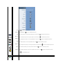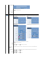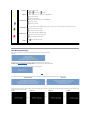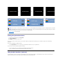
1
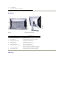
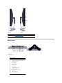
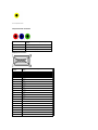
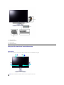
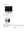
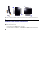
Dell™ 2408WFP Flat Panel Monitor User's Guide
About Your Monitor
Solving Problems
Product Features
Identifying Parts and Controls
Monitor specifications
Universal Serial Bus (USB) Interface
Card Reader Specifications Plug and Play Capability
Maintenance Guidelines
Setting Up the Monitor
Troubleshooting Your Monitor
Common Problems
Video Problems
Product Specific Problems
Universal Serial Bus (USB) Specific Problems
Troubleshooting the Dell™ Soundbar (Optional) Card Reader Troubleshooting
Appendix
Attaching the Stand
Connecting the Monitor
Organizing the Cables
Attaching the Soundbar (optional)
Removing the Stand
CAUTION: Safety Instruction
FCC Notice (U.S. Only)
Contacting Dell™
Operating the Monitor
Using the Front Panel Controls Using the On-Scree Display (OSD) Setting the Optimal Resolution Using the Dell Soundbar (Optional) Using the Tilt, Swivel and Vertical Extension
Rotating the Monitor
Adjusting the Rotating Settings of Your Operating System
Notes, Notices, and Cautions
Throughout this guide, blocks of text may be accompanied by an icon and printed in bold type or in italic type. These blocks are notes, notices, and cautions,
and they are used as follows:
NOTE: A NOTE indicates important information that helps you make better use of your computer.
NOTICE: A NOTICE indicates either potential damage to hardware or loss of data and tells you how to avoid
the problem.
CAUTION: A CAUTION indicates the potential for property damage, personal injury, or death.
Some warnings may appear in alternate formats and may be unaccompanied by an icon. In such cases, the specific presentation of the caution is mandated by
regulatory authority.
Information in this document is subject to change without notice.
© 2007 Dell™ Inc. All rights reserved.
Reproduction in any manner whatsoever without the written permission of Dell Inc. is strictly forbidden.
Trademarks used in this text: Dell, the DELL logo are trademarks of DellInc; Microsoft and Windows either registered trademarks or trademarks of Microsoft Corporation in the
United States and/or other countries. ENERGY STAR is a registered trademark of the U.S. Environmental Protection Agency. As an ENERGY STAR partner, Dell Inc. has determined
that this product meets the ENERGY STAR guidelines for energy efficiency.
Other trademarks and trade names may be used in this document to refer to either the entities claiming the marks and names or their products. Dell Inc. disclaims any
proprietary interest in trademarks and trade names other than its own.
Model 2408WFP
December 2007 Rev. A00
Back to Contents Page
About Your Monitor Dell™ 2408WFP Flat Panel Monitor User's Guide
Product Features
Identifying Parts and Controls
Monitor Specifications
Universal Serial Bus (USB) Interface
Card Reader Specifications Plug and Play Capability
Maintenance Guidelines
Product Features
The 2408WFP flat panel display has an active matrix, thin-film transistor (TFT), liquid crystal display (LCD). The monitor features include:
■ 24-inch (609.6 mm) viewable area display.
■ 1920 x 1200 resolution, plus full-screen support for lower resolutions.
■ Wide viewing angle to allow viewing from a sitting or standing position, or moving side-to-side.
■ Tilt, swivel, vertical extension and rotate adjustment capabilities.
■ Removable pedestal and Video Electronics Standards Association (VESA) 100 mm mounting holes for flexible mounting solutions.
■ Plug and play capability if supported by your system.
■ On-Screen Display (OSD) adjustments for ease of set-up and screen optimization.
■ Software and documentation CD includes an information file (INF), Image color Matching File (ICM), and product documentation.
■ Energy Saver feature for Energy Star compliance.
■ Security lock slot.
Identifying Parts and Features
Front View
Front View
Front panel controls
Label Description
1
Input Source Select
2
Picture In Picture (PIP)/Picture By Picture (PBP) Select
3
OSD Menu/Select 4
Brightness & Contrast/Down (-)
5
Auto-adjust/Up (+)
6
Power button (with power light indicator)
Back View
Back view Back View with monitor stand
Label
Description/Use
1
VESA mounting holes (100mm)
(Behind attached base plate)
To mount the monitor.
2
Connectors label
To indicate the positions and types of connectors.
3
Barcode serial number label
To contact Dell for technical support.
4
Security lock slot
To help secure your monitor.
5
Stand release button
To release the stand from the monitor.
6
Regulatory rating label
Lists the regulatory approvals.
7
Dell Soundbar mounting brackets
To attach the optional Dell Soundbar.
8
Lock down/release button
Push the monitor down, press the button to unlock the
monitor, and then lift the monitor to the desired height.
9
Cable management slot
To organize cables by placing them through the slot.
Side View
Left side
Right side
Label Description
1
Card reader. See Card Reader Specifications for more information. 2
USB downstream ports
Bottom View
Bottom view
Label Description
1
AC power cord connector
2
DC power connector for Dell™ Soundbar
3
DisplayPort connector
4
HDMI connector
5
DVI connector-1
6
DVI connector-2
7
VGA connector
8
Composite video connector
9
S-Video connector
10
Component video connectors 11
Audio out
12
USB upstream port
13
USB downstream ports
Monitor Specifications
The following sections give you information about the various power management modes and pin assignments for various connectors for your monitor.
Power Management Modes
If you have VESA's DPMS compliance display card or software installed in your PC, the monitor automatically reduces its power consumption when not in use.
This is referred to as Power Save Mode*. If input from keyboard, mouse or other input devices is detected by the computer, the monitor will automatically
"wake up". The following table shows the power consumption and signaling of this automatic power-saving feature: VESA Modes
Horizontal
Sync
Vertical Sync
Normal operation
Active
Active-off mode
Inactive
Inactive
-
-
Switch off
Active
Video
Power
Indicator
Power Consumption
Active
Green
110 W (maximum)*
57 W (normal)**
Blanked
Amber
Less than 2 W
Off
Less than 1 W
-
* With Audio and USB
** Without Audio and USB
Activate the computer and wake up the monitor to gain access to the OSD.
NOTE: This monitor is ENERGY STAR®-compliant as well as TCO '99/TCO '03 power management
compatible.
NOTE: Zero power consumption in OFF mode can only be achieved by disconnecting the main cable from the
monitor.
Pin Assignments
VGA Connector
Pin
Number
15-pin Side of the
Connected Signal Cable
1
Video-Red 2
Video-Green
3
Video-Blue
4
GND
5
Self-test
6
GND-R
7
GND-G
8
GND-B
9
Computer 5V/3.3V
10
GND-sync
11
GND
12
DDC data
13
H-sync
14
V-sync
15
DDC clock
DVI Connector Pin
Number
24-pin Side of the Connected Signal
Cable
1
TMDS RX2-
2
TMDS RX2+
3
TMDS Ground
4
Floating
5
Floating
6
DDC Clock
7
DDC Data
8
Floating
9
TMDS RX1-
10
TMDS RX1+
11
TMDS Ground
12
Floating
13
Floating
14
+5V/+3.3V power
15
Self test 16
Hot Plug Detect
17
TMDS RX0-
18
TMDS RX0+
19
TMDS Ground
20
Floating
21
Floating
22
TMDS Ground
23
TMDS Clock+
24
TMDS Clock-
S-video Connector
Pin Number
5-pin Side of the Connected
Signal Cable (Cable not
included)
1
GND
2
GND
3
LUMA
4
CHROMA
5
GND
Composite Video Connector
Luma composite chroma
Component Video Connector
Pin Number
3-pin Side of the Connected Signal Cable (Cable not
included)
1
Y (Luminance signal)
2
Pb (Color differential signal)
3
Pr (Color differential signal)
DisplayPort Connector
Pin
Number
20-pin Side of the Connected Signal
Cable
1
ML0(p)
2
GND
3
ML0(n)
4
ML1(p)
5
GND
6
ML1(n)
7
ML2(p)
8
GND
9
ML2(n)
10
ML3(p)
11
GND
12
ML3(n)
13
GND
14
GND
15
AUX(p)
16
GND
17
AUX(n)
18
HPD
19
Re-PWR
20
PWR
HDMI Connector
Pin
Number
19-pin Side of the Connected Signal
Cable
1
TMDS DATA 2+
2
TMDS DATA 2 SHIELD
3
TMDS DATA 2-
4
TMDS DATA 1+
5
TMDS DATA 1 SHIELD
6
TMDS DATA 1-
7
TMDS DATA 0+
8
TMDS DATA 0 SHIELD
9
TMDS DATA 0-
10
TMDS CLOCK
11
TMDS CLOCK SHIELD
12
TMDS CLOCK-
13
Floating
14
Floating
15
DDC CLOCK (SDA)
16
DDC DATA (SDA)
17
GROUND
18
+5V POWER
19
HOT PLUG DETECT
Flat Panel Specifications
Screen type
Active matrix - TFT LCD
Screen dimensions
24 inches (24-inch diagonal viewable image size)
Preset display area:
Horizontal
Vertical
518.4 mm (20.4 inches)
324 mm (12.7 inches)
Pixel pitch
0.27 mm
Viewing angle
178° (Vertical) typical, 178° (Horizontal) typical Luminance output
400 cd/m ²(typ)
Contrast ratio
1300:1 (typ), 3000:1 (typ, Dynamic Contrast on)
Faceplate coating
Antiglare with hard-coating 3H
Backlight
7 CCFL U-type system
Response Time
6ms panel typical (Grey to Grey)
Color Gamut
110%* typical
* 2408WFP Color Gamut (Typical) is based on CIE1976 (110%) and CIE1931 (102%).
Resolution
Horizontal scan range
30 kHz to 83 kHz (automatic)
Vertical scan range
56 Hz to 75 Hz
Optimal preset resolution
1920 x 1200 at 60 Hz
Highest preset resolution
1920 x 1200 at 60 Hz
Video Supported Modes
Video display capabilities (DVI playback)
480p/576p/720p/1080p (Supports HDCP)
Video display capabilities (Composite playback) NTSC/PAL
Video display capabilities (S-Video playback)
NTSC/PAL
Video display capabilities (HDMI playback)
480i/480p/576i/576p/720p/1080i/1080p
Video display capabilities (Component playback) 480i/480p/576i/576p/720p/1080i/1080p
Preset Display Modes
The following table lists the preset modes for which Dell guarantees image size and centering:
Display Mode
Horizontal
Frequency (kHz)
Vertical
Frequency (Hz)
Pixel Clock
(MHz)
Sync Polarity
(Horizontal/Vertical)
VGA, 720 x 400
31.5
70.1
28.3
-/+
VGA, 640 x 480
31.5
59.9
25.2
-/-
VESA, 640 x 480
37.5
75.0
31.5
-/-
VESA, 800 x 600
37.9
60.3
40.0
+/+
VESA, 800 x 600
46.9
75.0
49.5
+/+
VESA, 1024 x 768
48.4
60.0
65.0
-/-
VESA, 1024 x 768
60.0
75.0
78.8
+/+
VESA, 1152 x 864
67.5
75.0
108.0
+/+
VESA, 1280 x 1024
64.0
60.0
108.0
+/+
VESA, 1280 x 1024
80.0
75.0
135.0
+/+
VESA, 1600 x 1200
75.0
60.0
162.0
+/+
VESA, 1920 x 1200
74.5
60.0
154.0
+/-
Electrical
The following table lists the electrical specification:
Video input signals
Analog RGB, 0.7 Volts +/-5%, 75 ohm input impedance Digital DVI-D TMDS, 600mV for each differential line, 50 ohm input
impedance
HDMI, 600mV for each differential line, 100 ohm input impedance
per differential pair
DisplayPort, 600mV for each differential line, 100 ohm input
impedance per differential pair
S-video, Y input 1 volt(p-p), C input 0.286 volt(p-p), 75 ohm input
impedance
Composite, 1 volt(p-p), 75 ohm input impedance
Component: Y, Pb, Pr are all 0.5~1volt(p-p), 75 ohm input
impedance Synchronization input signals
separate horizontal and vertical,
3.3V CMOS or 5V TTL level, positive or negative sync.
SOG (Sync on green)
AC input voltage/frequency/current
100 to 240 VAC/50 or 60 Hz + 3 Hz/2.0A (Max.)
Inrush current
120V: 40A (Max.)
240V: 80A (Max.)
Physical Characteristics
The following table lists the physical characteristics:
Connector type
l
l
l
l
l
l
l
Signal cable type
l
l
l
l
l
l
l
D-sub: blue connector
DVI-D: white connector
DisplayPort: black connector
S-video
Composite
Component
HDMI
D-sub: Detachable, Analog, 15pin, shipped attached to the
monitor
DVI-D: Detachable, Digital, 24pin, shipped detached from
the monitor
DisplayPort: Detachable, Digital, 20pin, shipped detached
from the monitor
S-video
Composite
Component
HDMI
NOTE: The S-video, composite, component, and HDMI
cables are not included with the monitor.
Dimensions (with stand)
Height (Compressed)
396.8 mm (15.62 inches)
Height (Extended)
496.8 mm (19.56 inches)
Width
559.7 mm (22.04 inches)
Depth
207.6 mm (8.17 inches)
Dimensions (without stand)
Height
359.6 mm (14.4 inches)
Width
559.7 mm (22.04 inches)
Depth
87.5 mm (3.44 inches)
Stand Dimensions
Height (Compressed)
338.2 mm (13.31 inches)
Height (Extended)
379.2 mm (14.93 inches)
Width
432 mm (17.01 inches)
Depth
207.6 mm (8.17 inches)
Weight Weight with packaging
11.7 kg ( 26.41 lb)
Weight with stand assembly and cables
9.58 kg ( 21.74 lb)
Weight without stand assembly
(For wall mount or VESA mount considerations - no cables)
6.74 kg ( 15.48 lb)
Weight of stand assembly
2.16 kg (4.76 lb)
Environmental
The following table lists the environmental limitation:
Temperature
5° to 35°C (41° to 95°F)
Operating
Storage: 0° to 60°C (32° to 140°F)
Shipping: -20° to 60°C(-4° to 140°F)
Nonoperating
Humidity
10% to 80% (noncondensing)
Operating
Storage: 5% to 90% (noncondensing)
Shipping: 5% to 90%(noncondensing)
Nonoperating
Altitude
3,657.6 m (12,000 ft) max
Operating
12,192 m (40,000 ft) max
Nonoperating
Thermal dissipation
375 BTU/hour (maximum)
195 BTU/hour (typical)
Universal Serial Bus (USB) Interface
This monitor supports High-Speed Certified USB 2.0 interface.
Transfer speed
Data Rate
Power
Consumption
High speed
480 Mbps
2.5W (Max., each port)
Full speed
12 Mbps
2.5W (Max., each port)
Low speed
1.5 Mbps
2.5W (Max., each port)
USB Upstream Connector
Pin Number
4-pin Side of the connector
1
DMU
2
VCC
3
DPU
4
GND
USB Downstream Connector
Pin Number
4-Pin Side of the Signal Cable
1
VCC
2
DMD
3
DPD
4
GND
USB Ports
l
l
1 upstream - rear
4 downstream - 2 on rear; 2 on left side
NOTE: USB 2.0 capability requires 2.0 capable computer NOTE: The monitor's USB interface works only when the monitor is on or in power save mode. If you switch
the monitor off and then on, the attached peripherals may take a few seconds to resume normal functionality.
Card Reader Specifications Overview
l
l
l
l
The Flash Memory Card Reader is a USB storage device that allows users to read and write information from and into the memory card.
The Flash Memory Card Reader is automatically recognized by Windows® 2000, XP and Vista.
Once installed and recognized, each separate memory card (slot) appears as a separate drive/drive letter.
All standard file operations (copy, delete, drag-and-drop, etc.) can be performed with this drive.
Features
The Flash Memory Card Reader has the following features:
l
l
l
l
l
Supports Windows 2000, XP and Vista operating systems
No Windows 9X support from Dell
Mass Storage Class device (No drivers are required under Windows 2000, XP and Vista)
USB-IF certification
Supports various memory card media
The following table lists the slot to support what kind of memory card:
Slot Number
Flash memory cards type
1
Compact Flash type I/II Card (CF I/II)/CF form factor ATA hard drives to USB 2.0 bus
2
xD-Picture Card
Memory Stick Card (MS)/High Speed Memory Stick (HSMS)/Memory Stick Pro Card (MS
PRO)/Memory Stick Duo (with Adapter)
Secure Digital Card (SD)/Mini Secure Digital (with Adapter)/TransFlash Card (with
Adapter)
MultiMedia Card (MMC)/Reduced Size MultiMedia Card (with Adapter)
Maximum Card Capacity Supported by the 2408WFP card reader
Card type
Support Specification
Memory Card
Spec Version
Max. capacity
CF
Compact Flash Specification
2.0
128GB
MS
Memory Stick Standard Format Specification
1.40-00
128MB
MSPRO
Memory Stick Pro Standard Format Specifications
1.01-01
32GB
MSDuo
Memory Stick Duo Standard Format Specifications
1.10-00
128MB/32GB
xD
xD Picture Card Specification
1.2
2GB
SD
SD Memory Card Specifications
2.0
32GB
MMC
MultiMedia Card System Specification
4.2
32GB
NOTE: SD includes MiniSD NOTE: MMC includes RS-MMC
General
Connection type
USB 2.0 High Speed Device (USB Full Speed Device compatible)
Supported OS
Windows 2000, XP and Vista
Performance
Transfer Speed
Read: 480 Mb/s (max.)
Write: 480 Mb/s (max.)
Plug and Play Capability
You can install the monitor in any Plug and Play-compatible system. The monitor automatically provides the computer system with its Extended Display
Identification Data (EDID) using Display Data Channel (DDC) protocols so the system can configure itself and optimize the monitor settings. If required, the
user can select different settings, but in most cases monitor installation is automatic.
Maintenance Guidelines
Caring for Your Monitor
CAUTION: Read and follow the Safety Instructions before cleaning the monitor. CAUTION: Before cleaning the monitor, unplug the monitor from the electrical
outlet. For best practices, follow the instructions in the list below while unpacking, cleaning, or handling your monitor:
l
l
l
l
To clean your antistatic screen, lightly dampen a soft, clean cloth with water. If possible, use a special screen-cleaning tissue or solution suitable for the
antistatic coating. Do not use benzene, thinner, ammonia, abrasive cleaners, or compressed air.
Use a lightly-dampened, warm cloth to clean the plastics. Avoid using detergent of any kind as some detergents leave a milky film on the plastics. If you notice a white powder when you unpack your monitor, wipe it off with a cloth.
Handle your monitor with care as dark-colored monitors may scratch and show white scuff marks more than lighter-colored monitors. Back to Contents Page
Back to Contents Page
Appendix
Dell™ 2408WFP Flat Panel Monitor User's Guide Safety Instructions
FCC Notice (U.S. Only)
Contacting Dell™
CAUTION: Safety Instructions
CAUTION: Use of controls, adjustments, or procedures other than those specified in this documentation may result in exposure to shock,
electrical hazards, and/or mechanical hazards.
Read and follow these instructions when connecting and using your computer monitor:
l
l
To help avoid damaging your computer, be sure that the voltage selection switch on the power supply for the computer is set to match the alternating current (AC) power available at your location:
¡
115 volts (V)/60 hertz (Hz) in most of North and South America and some Far Eastern countries such as Japan, South Korea (also 220 volts (V)/60
hertz (Hz)), and Taiwan.
¡
230 volts (V)/50 hertz (Hz) in most of Europe, the Middle East, and the Far East.
Always be sure that your monitor is electrically rated to operate with the AC power available in your location.
NOTE: This monitor does not need or have a voltage selection switch for setting the AC voltage input. It will automatically accept any AC input voltage
according to the ranges defined in the "Electrical Specifications" section in the User's Guide.
l
Do not store or use the monitor in locations that are exposed to heat, direct sunlight, or extreme cold.
l
Avoid moving the monitor between locations with large temperature differences.
l
Do not subject the monitor to severe vibration or high impact conditions. For example, do not place the monitor inside a car trunk.
l
Do not store or use the monitor in locations exposed to high humidity or dusty environment.
l
Do not allow water or other liquids to spill on or into the monitor.
l
Keep flat panel monitor in room temperature conditions. Excessive cold or hot conditions can have an adverse effect on the liquid crystal of the display.
l
Never insert anything metallic into the monitor openings. Doing so may create the danger of electric shock.
l
To avoid electric shock, never touch the inside of the monitor. Only a qualified technician should open the monitor case.
l
Never use your monitor if the power cable has been damaged. Ensure that nothing rests on your computer's cables and that the cables are not located
where they can be stepped on or tripped over.
l
Be sure to grasp the plug, not the cable, when disconnecting the monitor from an electric socket.
l
Openings in the monitor cabinet are provided for ventilation. To prevent overheating, these openings should not be blocked or covered. Avoid using the
monitor on a bed, sofa, rug, or other soft surface, as doing so may block the ventilation openings in the bottom of the cabinet. If you place the monitor
in a bookcase or an enclosed space, be sure to provide adequate ventilation and air flow.
l
Place your monitor in a location with low humidity and minimum dust. Avoid places similar to a damp basement or dusty hallway.
l
Do not expose the monitor to rain or use it near water (in kitchens, next to swimming pools, etc.). If the monitor accidentally gets wet, unplug it and
contact an authorized dealer immediately. You can clean the monitor with a damp cloth when necessary, being sure to unplug the monitor first.
l
Place the monitor on a solid surface and treat it carefully. The screen is made of glass and can be damaged if dropped or hit sharply.
l
Locate your monitor near an easily accessible electric outlet.
l
If your monitor does not operate normally - in particular, if there are any unusual sounds or smells coming from it - unplug it immediately and contact an
authorized dealer or service center.
l
Do not attempt to remove the back cover, as you will be exposed to an electrical shock hazard. The back cover should only be removed by qualified
service personnel.
l
High temperatures can cause problems. Don't use your monitor in direct sunlight, and keep it away from heaters, stoves, fireplaces, and other sources
of heat.
l
Unplug the monitor when it is going to be left unused for an extended period of time.
l
Unplug your monitor from the electric outlet before any service is performed.
l
LAMP(S) INSIDE THIS PRODUCT CONTAIN(S) MERCURY AND MUST BE RECYCLED OR DISPOSED OFF ACCORDING TO LOCAL, STATE OR
FEDERAL LAWS. FOR MORE INFORMATION, GO TO WWW.DELL.COM/HG OR CONTACT THE ELECTRONIC INDUSTRIES ALLIANCE AT
WWW.EIAE.ORG.
FCC Notice (U.S. Only)
FCC Class B
This equipment generates, uses, and can radiate radio frequency energy and, if not installed and used in accordance with the manufacturer's instruction
manual, may cause interference with radio and television reception. This equipment has been tested and found to comply with the limits for a Class B digital
device pursuant to Part 15 of the FCC Rules.
This device complies with Part 15 of the FCC Rules. Operation is subject to the following two conditions:
1.
2.
This device may not cause harmful interference.
This device must accept any interference received, including interference that may cause undesired operation.
NOTICE: The FCC regulations provide that changes or modifications not expressly approved by Dell™ Inc. could void your authority to operate this equipment.
These limits are designed to provide reasonable protection against harmful interference in a residential installation. However, there is no guarantee that
interference will not occur in a particular installation. If this equipment does cause harmful interference with radio or television reception, which can be
determined by turning the equipment off and on, you are encouraged to try to correct the interference by one or more of the following measures:
l
l
l
l
Reorient the receiving antenna.
Relocate the system with respect to the receiver.
Move the system away from the receiver.
Plug the system into a different outlet so that the system and the receiver are on different branch circuits.
If necessary, consult a representative of Dell™ Inc. or an experienced radio/television technician for additional suggestions.
The following information is provided on the device or devices covered in this document in compliance with the FCC regulations:
l
l
l
Product name: 2408WFP Flat Panel Monitor
Model number: 2408WFPb
Company name:
Dell Inc.
Worldwide Regulatory Compliance & Environmental Affairs
One Dell Way
Round Rock, Texas 78682 USA
512-338-4400
Contacting Dell™
To contact Dell electronically, you can access the following websites and by phone:
l
l
For support through the web, go to support.dell.com.
For customers in the United States, call 800-W W W-DELL (800-999-3355).
NOTE: If you do not have an active Internet connection, you can find contact information on your purchase invoice, packing slip, bill, or Dell product
catalog.
Dell provides several online and telephone-based support and service options. Availability varies by country and product, and some services may not be
available in your area. To contact Dell for sales, technical support, or customer service issues:
1.
2.
3.
4.
5.
Visit support.dell.com.
Verify your country or region in the Choose A Country/Region drop-down menu at the bottom of the page.
Click Contact Us on the left side of the page.
Select the appropriate service or support link based on your need.
Choose the method of contacting Dell that is convenient for you.
Back to Contents Page
Back to Contents Page
Setting Up Your Monitor
Dell™ 2408WFP Flat Panel Monitor If you have a Dell™ desktop or a Dell™ portable computer with internet access
1. Go to http://support.dell.com, enter your service tag, and download the latest driver for your graphics card.
2. After installing the drivers for your Graphics Adapter, attempt to set the resolution to 1920x1200 again.
NOTE: If you are unable to set the resolution to 1920x1200, please contact Dell™ to inquire about a Graphics Adapter that supports these resolutions. Back to Contents Page
Back to Contents Page
Setting Up Your Monitor
Dell™ 2408WFP Flat Panel Monitor If you have non Dell™ desktop, portable computer, or graphic card
1. Right-click on the desktop and click Properties.
2. Select the Settings tab.
3. Select Advanced.
4. Identify your graphics controller supplier from the description at the top of the window (e.g. NVIDIA, ATI, Intel etc.).
5. Please refer to the graphic card provider website for updated driver (for example, http://www.ATI.com OR http://www.NVIDIA.com ).
6. After installing the drivers for your Graphics Adapter, attempt to set the resolution to 1920x1200 again.
NOTE: If you are unable to set the resolution to 1920x1200, please contact the manufacturer of your computer or consider purchasing a graphics adapter
that will support the video resolution of 1920x1200. Back to Contents Page
Back to Contents Page
Operating the Monitor
Dell™ 2408WFP Flat Panel Monitor User's Guide
Using the Front Panel Controls
Using the On-Scree Display (OSD) Menu
Setting the Optimal Resolution
Using the Dell Soundbar (Optional)
Using the Tilt, Swivel and Vertical Extension
Rotating the Monitor
Adjusting the Rotating Settings of Your Operating System
Using the Front Panel
Use the buttons on the front of the monitor to adjust the image settings. A
Use Input Source Select button to select between two different video signals that may be connected to your monitor.
l
l
l
Input Source Select
l
l
l
l
l
VGA input
DVI-D 1 input
DVI-D 2 input
DisplayPort input
HDMI input
Component video input
S-Video input
Composite video input
As you cycle through the inputs you will see the following messages to indicate the currently selected input source. It may take a few
seconds for the image to appear.
or
or
or
or
If either VGA or DVI-D input is selected and both VGA and DVI-D cables are not connected, a floating dialog box as shown below appears.
or
If either S-Video, Composite, HDMI or Component input is selected and the cables are not connected or the video source is turned off, the
screen does not have an image. If any button is pressed (except power button), the monitor displays the following message:
B
Use this button to activate PIP (Picture-in-Picture)/PBP (Picture-by-Picture) modes adjustment. Pressing this button continually cycles the monitor through the following modes : OFF-->PIP-->PBP. You will see the following messages
corresponding to the mode selected.
PIP/PBP Select
→
→
C
The Menu button is used to open and exit the on-screen display (OSD), and exit from menus and sub-menus. See Using the OSD Menu
OSD Menu/Select
D
Use this button for direct access to the "Brightness" and "Contrast" control menu.
Brightness /Contrast
Hot Key
D
and
E
Use these buttons to adjust (decrease/increase ranges) items in the OSD menu.
Down (-) and Up (+)
E
Use this button to activate automatic setup and adjustment. The following dialog appears on a black screen as the monitor self
the current input:
Auto Adjust
Auto Adjustment
button allows the monitor to self-adjust to the incoming video signal. After using Auto Adjustment, you can further
tune your monitor by using the Pixel Clock (Coarse), Phase (Fine) controls in the OSD.
NOTE: Auto Adjust does not occur if you press the button while there are no active video input signals or attached cables.
F
Use the power button to turn the monitor on and off. Power button
(with power light indicator)
The green light indicates the monitor is on and fully functional. An amber light indicates power save mode.
Using the OSD Menu
NOTE: If you change the settings and then either proceed to another menu, or exit the OSD menu, the monitor automatically saves those changes. The changes are also saved if you change the settings and then wait for the OSD menu to disappear.
1. Push the MENU button to launch the OSD menu and display the main menu.
Main Menu for Analog (VGA) Input
Or
Main Menu for non Analog (non VGA) Input
NOTE: AUTO ADJUST is only available when you are using the analog (VGA) connector.
2. Push the
for a and
buttons to move between the setting options. As you move from one icon to another, the option name is highlighted. See the table
complete list of all the options available for the monitor.
3. Push the MENU button once to activate the highlighted option. 4. Push
and
button to select the desired parameter.
5. Push MENU to enter the slide bar and then use the and
buttons, according to the indicators on the menu, to make your changes.
6. Select the "back" option to return to the main menu or "exit" to exit the OSD menu.
Icon
Menu and
Submenus
Description
EXIT
Select to exit the main menu.
BRIGHTNESS
& CONTRAST
This menu is to activate Brightness/Contrast adjustment.
Back
Brightness
Push
to go back to the main menu.
Brightness adjusts the luminance of the backlight.
Push the
Contrast
button to increase brightness and push the button to decrease brightness (min 0 ~ max 100).
Adjust Brightness first, and then adjust Contrast only if further adjustment is necessary.
Push the
button to increase contrast and push the
button to decrease contrast (min 0 ~ max 100).
The Contrast function adjusts the degree of difference between darkness and lightness on the monitor screen.
Exit Menu
Push
to exit the OSD main menu.
AUTO ADJUST
Even though your computer recognizes your monitor on startup, the Auto Adjustment function optimizes the display settings for use with your partic
setup.
NOTE: In most cases, Auto Adjust produces the best image for your configuration.
NOTE: AUTO ADJUST option is only available when you are using the analog (VGA) connector.
INPUT
SOURCE
The INPUT SOURCE menu is to select between different video signals that may be connected to your monitor.
Back
Auto Select
VGA
DVI-D 1 & 2
DisplayPort
HDMI
Component
S-Video
Push
to go back to the main menu.
Scan for Sources. Push
to scan for available input signals.
Select VGA input when you are using the analog (VGA) connector. Push
to select the VGA input source.
Select DVI-D input when you are using the Digital (DVI) connector. Push
to select the DVI input source.
Select DisplayPort input when you are using DisplayPort connector. Push
Select HDMI input when you are using HDMI connector. Push
to select the DisplayPort input source. to select the HDMI input source. Select Component input when you are using component video connector. Push
Select S-Video input when you are using S-Video connector. Push
to select the component input source.
to select the S-Video input source.
Composite
Select Composite input when you are using composite video connector. Push
to select the composite input source.
Exit Menu
Push
to exit the OSD main menu.
PRESET
MODES
There are several image modes for different usage.
Image mode submenu for VGA/DVI-D input
Image mode submenu for Video input
or
NOTE: Image modes are different between the VGA/DVI-D and Video inputs
Back
Input Color Format
Gamma
Color Setting mode
VGA/DVI-D input
Desktop Mode
Push
to go back to the main menu.
To achieve the different color domain for PC RGB and HD YPbPr (HD YPbPr is suitable for HD video playback over DVI. PC RGB is suitable for normal PC
graphics display over DVI).
To achieve the different color mode for PC and Mac.
You can choose between a Graphics and a Video mode. If your computer is connected to your monitor, choose Graphics. If a DVD, STB, or VCR is con
your monitor, choose Video.
Mode suitable for desktop applications.
Multimedia Mode
Mode for multimedia applications, eg video playback.
Game Mode
Mode suitable for gaming applications.
sRGB Mode
Mode to emulate 72% NTSC color.
Warm Mode
Warm mode is selected to obtain a red tint. This color setting is typically used for color-intensive applications (photograph image editing, multimedia,
etc.).
Cool Mode
Cool mode is selected to obtain a bluish tint. This color setting is typically used for text based applications (spreadsheets, programming, text editors
Custom (R, G, B)
Use the
or
button to increase or decrease each of the three colors (R, G, B) independently, in single-digit increments, from 0 to 100.
Video input
Movie Mode
Mode suitable for movie playback.
Game Mode
Mode suitable for game applications.
Sports Mode
Mode suitable for sports scenes.
Nature Mode
Mode suitable for nature scenes.
Hue
User Preset: Use the plus and minus buttons to increase or decrease each of the three colors (R, G, B) independently, in single digit increments, from
100.
makes video image shade into greenish
makes video image shade into purplish
NOTE: Hue adjustment only available for video input.
Saturation
This feature can make color shift of video image to green or purple. This is used to adjust for desired flesh tone color. Use '100'.
makes video image looks more monochrome
makes video image looks more colorful
Exit Menu
Push
DISPLAY
SETTINGS
to exit the OSD main menu.
Back
Wide Mode
Push
to go back to the main menu.
Adjust the image ratio as 1:1, aspect or full screen.
NOTE: Wide Mode adjustment is not required at optimal preset resolution 1920 x 1200.
Horizontal Position
Use the
and
buttons to adjust image left and right. Minimum is '0' (-). Maximum is '100' (+).
Vertical Position
Use the
and
buttons to adjust image up and down. Minimum is '0' (-). Maximum is '100' (+).
Sharpness
Zoom
This feature can make the image look sharper or softer. Use
Using the
Horizontal Pan
Vertical Pan
or
to adjust the sharpness from '0' to '100' .
Use the Zoom function to zoom in to specific area of interest.
and
keys to zoom in and out.
After zooming in, the horizontal and vertical pan function allows you to pan the enlarged image left/right and up/down respectively.
Use the
and
buttons to adjust image left and right. Minimum is '0' (-). Maximum is '100' (+).
Use the
and
buttons to adjust image up and down. Minimum is '0' (-). Maximum is '100' (+).
Pixel Clock
The Phase and Pixel Clock adjustments allow you to adjust your monitor to your preference. These settings are accessed through the main OSD men
selecting 'Image Settings'.
Use the
Phase
and
buttons to adjust for best image quality.
If satisfactory results are not obtained using the Phase adjustment, use the Pixel Clock (coarse) adjustment and then use Phase (fine), again. NOTE: Pixel Clock and Phase Adjustments are only available for "VGA" input.
Dynamic Contrast
Dynamic contrast allows you to increase the level of contrast to provide sharper and more detailed image quality. Display Info
Display Reset
Exit Menu
All the settings related to this monitor.
Reset the image to the original factory setting.
Push
to exit the OSD main menu.
OTHER
SETTINGS
Back
Language
Menu Transparency
Menu Timer
Push
This function is used to adjust the OSD background from opaque to transparent.
OSD Hold Time: Sets the length of time the OSD will remain active after the last time you pressed a button.
Use the
Menu Lock
to go back to the main menu.
Language option to set the OSD display to one of five languages (English, Espanol, Francais, Deutsch, Japanese).
and
buttons to adjust the slider in 5 second increments, from 5 to 60 seconds.
Controls user access to adjustments. When 'Yes' (+) is selected, no user adjustments are allowed. All buttons are locked except the menu
NOTE: When the OSD is locked, pressing the menu button will take the user directly to the OSD settings menu, with 'OSD Lock' pre
Select No(-) to unlock and allow user access to all applicable settings.
Rotates the OSD by 90 degrees counter-clockwise. Your can adjust according to your Display Rotation.
Menu Rotation
To turn on or off Audio Power during Power Save mode.
Audio Option
DDC/CI
DDC/CI (Display Data Channel/Command Interface) allows your monitor parameters (brightness, color balance etc) to be adjustable via software on
You can disable this feature by selecting "Disable".
Enable this feature for best user experience and optimum performance of your monitor.
If an image appears to be stuck on the monitor, select LCD Conditioning to help eliminate any image retention. Using the LCD Conditioning feature
several hours. Severe cases of image retention are known as burn-in, the LCD Conditioning feature does not remove burn-
LCD Conditioning
Reset all OSD settings to the factory preset values.
Push
to exit the OSD main menu.
Factory Reset
Exit Menu
PIP
SETTINGS
This function brings up a window displaying image from another input source.
PIP/PBP submenu when PIP/PBP OFF (main source is VGA/DVI-D input) PIP/PBP submenu when PIP/PBP OFF (main source is Video input) or PIP/PBP submenu when PIP/PBP ON (main source is VGA/DVI-D input) PIP/PBP submenu when PIP/PBP ON (main source is Video input) or
NOTE: When using DVI source, the contrast adjustment is not available.
Back
Mode
Push
to go back to the main menu.
There is two modes: PIP (Picture in Picture) and PBP (Picture By Picture)
Use
and to browse and to select "Off", "PIP" or "PBP".
When PIP/PBP is activated, select "Swap" to exchange the input source for the main screen and PIP/PBP window.
When PIP/PBP
activated
PIP/PBP Source
Select an input signal for PIP/PBP. (VGA/DVI-D 1/DVI-D 2/DP (DisplayPort)/HDMI/S-Video/Composite/Component)
Use
PIP Size
and to browse and to select.
Select PIP window size.
Use
and to browse and to select.
PIP Position
Select PIP window position.
Use
Brightness
and to browse and to select.
Adjust the brightness level of the picture in PIP/PBP Mode.
reduce the brightness
increases the brightness
PIP/PBP Contrast
Adjust the contrast level of the picture in PIP/PBP Mode.
reduce the contrast
increases the contrast
PIP/PBP Hue/Tint
This function shifts the color of PIP/PBP image to green or purple. This is used to adjust for desired flesh tone color.
shifts image color towards green
shifts image color towards purple
Adjust the color saturation of PIP/PBP image.
PIP/PBP Saturation
makes the image look more monochrome
makes the image look more colorful
Exit Menu
Push
to exit the OSD main menu.
OSD Warning Messages
When the monitor does not support a particular resolution mode you will see the following
message :
This means that the monitor cannot synchronize with the signal that it is receiving from the
computer. See Monitor Specifications for the Horizontal and Vertical frequency ranges addressable by this monitor. Recommended mode is 1920 X 1200.
When monitor enters Power Save mode, the following message appears : Activate the computer and wake up the monitor to gain access to the OSD
If you press any button other than the power button one of the following messages will appear depending on the selected input:
VGA/DVI-D input
Video Input
or
In PIP mode, when the monitor does not sense the selected second signal input, one of the following messages will appear depending upon the selected input
as long as the OSD screen is closed.
1. VGA 2. DVI-D 1
3. DVI-D 2
4. HDMI or 5. DisplayPort
6. S-Video
or
or
7. Composite
8. Component
or
or
or
If either VGA, DVI-D, HDMI or DisplayPort input is selected and all VGA, DVI-D, HDMI and DisplayPort cables are not connected, a floating dialog box as shown below appears.
or
or
or NOTE: When the cable is connected back to the input of the monitor, any active PIP/PBP window will disappear. Please enter PIP/PBP submenu to bring back the PIP
NOTE: The PIP/PBP functions can bring up a picture from a second image source. Thus you can watch images from 1 PC source (D-Sub or DVI) and 1 Video Source (Composite or S
functions will not allow for 2 PC sources or 2 Video sources to perform PIP/PBP.
See Solving Problems for more information.
Setting the Optimal Resolution
1.
2.
3.
4.
Right-click on the desktop and select Properties.
Select the Settings tab.
Set the screen resolution to 1920 x 1200.
Click OK.
If you do not see 1920 x 1200 as an option, you may need to update your graphics driver. Depending on your computer, complete one of the following
procedures.
If you have a Dell desktop or portable computer:
¡
Go to support.dell.com, enter your service tag, and download the latest driver for your graphics card.
If you are using a non-Dell computer (portable or desktop):
¡
¡
Go to the support site for your computer and download the latest graphic drivers.
Go to your graphics card website and download the latest graphic drivers.
Using the Dell Soundbar (Optional)
The Dell Soundbar is a stereo two channel system adaptable to mount on Dell flat panel displays. The Soundbar has a rotary volume and on/off control to
adjust the overall system level, a blue LED for power indication, and two audio headset jacks.
1.
Attach mechanism
2.
Headphone connectors
3. Power indicator
4.
Power/Volume control
Using the Tilt, Swivel and Vertical Extension
Tilt/Swivel
With the built-in pedestal, you can tilt and/or swivel the monitor for the most comfortable viewing angle.
NOTE: Stand is detached and extended when the monitor is shipped from the factory.
Vertical Extension
Stand extends vertically up to 100mm via the Lock down/release button. NOTE: If you monitor gets locked down:
1. Push the monitor down.
2. Press the Lock down/release button on the bottom rear of stand to unlock the monitor.
3. Lift the monitor up and extend the stand to the desired height.
NOTICE: Before relocating or moving the monitor to a different location, make sure that the stand is locked down. To lock it down, lower the height of
the panel until it clicks and is locked into place.
Rotating the Monitor
Before you rotate the monitor, your monitor should be fully vertically extended (Vertical Extension) and fully tilted (Tilt) up to avoid hitting the bottom edge of
the monitor.
NOTE: To take advantage of the "Display Rotation" function (Landscape versus Portrait view) an updated graphics driver is required for your Dell™ Computer not included with this monitor. Please download the graphics driver from support.dell.com and refer to the "download" section for "Video
Drivers" for latest driver updates.
NOTE: When in "Portrait View Mode", you may experience performance degradation in graphic-intensive applications (3D Gaming etc.)
Adjusting the Rotating Settings of Your Operating System After you have rotated your monitor, you need to complete the procedure below to rotate your operating system.
NOTE: If you are using the monitor with a non-Dell computer, you need to go to the graphics driver website or your computer manufacturer website for information on rotating your operating system. 1.
2.
3.
Right-click on the desktop and click Properties.
Select the Settings tab and click Advanced.
If you have ATI graphics card, select the Rotation tab and set the preferred rotation.
If you have nVidia graphics card, click the nVidia tab, in the left-hand column select NVRotate, and then select the preferred rotation.
If you have Intel graphics card, select the Intel graphics tab, click Graphic Properties, select the Rotation tab, and then set the preferred rotation.
NOTE: If you do not see the rotation option or it is not working correctly, go to support.dell.com and download the latest driver for your graphics card.
Back to Contents Page
Back to Contents Page
Setting Up Your Monitor
Dell™ 2408WFP Flat Panel Monitor Important instructions to set the display resolution to 1920x1200 (Optimal)
For optimal display performance while using the Microsoft Windows® operating systems, set the display resolution to 1920 x 1200 pixels by performing the
following steps:
1. Right-click on the desktop and click Properties.
2. Select the Settings tab.
3. Move the slider-bar to the right by pressing and holding left-mouse button and adjust the screen resolution to 1920x1200.
4. Click OK.
If you do not see 1920x1200 as an option, you may need to update your graphics driver. Please choose the scenario below that best describes the
computer system you are using, and follow the provided directions:
1: If you have a Dell™ desktop or a Dell™ portable computer with internet access.
2: If you have non Dell™ desktop, portable computer, or graphic card.
Back to Contents Page
Dell™ 2408WFP Flat Panel Monitor User Guide
Important instructions to set the display resolution to 1920x1200(Optimal)
Information in this document is subject to change without notice.
© 2007 Dell Inc. All rights reserved.
Reproduction in any manner whatsoever without the written permission of Dell Inc. is strictly forbidden.
Trademarks used in this text: Dell, the DELL logo, are trademarks of DellInc; Microsoft and Windows either registered trademarks or trademarks of Microsoft Corporation in the
United States and/or other countries. Adobe is a trademark of Adobe Systems Incorporated, which may be registered in certain jurisdictions. ENERGY STAR is a registered trademark
of the U.S. Environmental Protection Agency. As an ENERGY STAR partner, Dell Inc. has determined that this product meets the ENERGY STAR guidelines for energy efficiency.
Other trademarks and trade names may be used in this document to refer to either the entities claiming the marks and names or their products. Dell Inc. disclaims any
proprietary interest in trademarks and trade names other than its own.
M o d el 2408WFP
December 2007 Rev. A00
Back to Contents Page
Setting Up the Monitor
Dell™ 2408WFP Flat Panel Monitor User's Guide
Attaching the Stand
Connecting the Monitor
Organizing Your Cables
Attaching the Soundbar (optional)
Removing the Stand Attaching the Stand
NOTE: The stand is detached when the monitor is shipped from the factory.
Place the stand on a flat surface and follow these steps to attach the monitor stand:
1.
2.
Fit the groove on the back of the monitor to the two tabs on the upper part of the stand.
Lower the monitor so that the monitor mounting area snaps on to or locks on to the stand.
Connecting Your Monitor
CAUTION: Before you begin any of the procedures in this section, follow the safety instructions.
To connect your monitor to the computer perform the following steps/instructions:
l
l
Turn off your computer and disconnect the power cable.
Connect either the white (digital DVI-D) display connector cable, the blue (analog VGA) display connector cable or the black DisplayPort cable to the
corresponding video port on the back of your computer. Do not use all the cables on the same computer. Use all the cables only when they are
connected to different computers with appropriate video systems. Connecting the white DVI cable
NOTE: Your monitor supports two DVI ports. You can either choose DVI-D 1 or DVI-D 2 via source select
button.
Connecting the blue VGA cable
Connecting the black DisplayPort cable
NOTE: The Graphics are used for the purpose of illustration only. Appearance of the the computer may vary.
After you have completed connecting the DVI/VGA/DisplayPort cable, follow the procedure below to complete your monitor setup:
l
l
l
Plug the power cables for your computer and monitor into a nearby outlet.
Turn on the monitor and the computer.
If your monitor displays an image, installation is complete. If it does not display an image, see Solving Problems.
Use the cable management slot on the monitor stand to organize the cables.
Organizing Your Cables
After attaching all necessary cables to your monitor and computer, (See Connecting Your Monitor for cable attachment,) use the cable management slot to
neatly organize all cables as shown above.
Attaching the soundbar
1. Working from the rear of the monitor, attach Soundbar by aligning the two slots with the two tabs along the bottom rear of the monitor.
2. Slide the Soundbar to the left until it snaps into place.
3. Connect the Soundbar with the DC power connector.
4. Insert the mini stereo plug from the rear of the Soundbar into the computer's audio output jack.
NOTICE: Do not use with any device other than Dell Soundbar
NOTE: Soundbar Power Connector +12V DC output is for optional Soundbar only.
Removing the Stand
NOTE: To prevent scratches on the LCD screen while removing the stand, ensure that the monitor is placed on a clean surface.
Complete the following steps to remove the stand:
1.
2.
3.
Rotate the stand to allow access to the stand release button.
Press and hold the stand release button.
Lift the stand up and away from the monitor.
Back to Contents Page
Back to Contents Page
Solving Problems
Dell™ 2408WFP Flat Panel Monitor User's Guide Monitor Specific Troubleshooting
Common Problems
Video Problems
Product Specific Problems
Universal Serial Bus (USB) Specific Problems
Troubleshooting the Dell™ Soundbar (Optional) Card Reader Troubleshooting
CAUTION: Before you begin any of the procedures in this section, follow the Safety Instructions.
Troubleshooting Your Monitor
Self-Test Feature Check (STFC)
Your monitor provides a self-test feature that allows you to check whether your monitor is functioning properly. If your monitor and computer are properly
connected but the monitor screen remains dark, run the monitor self-test by performing the following steps:
1.
2.
3.
Turn off both your computer and the monitor.
Unplug the video cable from the back of the computer. To ensure proper Self-Test operation, remove both Digital (white connector) and the Analog (blue
connector) cables from the back of computer.
Turn on the monitor.
The floating dialog box should appear on-screen (against a black background) if the monitor cannot sense a video signal and is working correctly.
While in self-test mode, the power LED remains green. Also, depending upon the selected input, one of the dialogs shown below will continuously
scroll through the screen.
or
or
4.
5.
This box also appears during normal system operation if the video cable becomes disconnected or damaged.
Turn off your monitor and reconnect the video cable; then turn on both your computer and the monitor.
If your monitor screen remains blank after you use the previous procedure, check your video controller and computer system, because your monitor is
functioning properly.
NOTE: Self test feature check is not available for S-Video, Composite and Component video modes.
OSD Warning Messages
For OSD-related issues, see OSD Warning Messages
Common Problems
The following table contains general information about common monitor problems you might encounter.
Common
Symptoms
No Video/ Power
LED off
What You
Experience
No picture
Possible Solutions
l
Ensure that the video cable connecting the monitor and the computer is
properly connected and secure.
l
l
No Video/ Power
LED on
Poor Focus
No picture
or no
brightness
l
Picture is
fuzzy,
blurry, or
ghosting
l
l
l
l
l
l
l
Shaky/Jittery
Video
Wavy
picture or
fine
movement
l
l
l
l
l
Missing Pixels
Stuck-on Pixels
Brightness
Problems
Geometric
Distortion
LCD screen
has spots
l
LCD screen
has bright
spots
l
Picture too
dim or too
bright
l
Screen not
centered
correctly
l
l
l
l
l
l
l
Verify that the power outlet is functioning properly using any other electrical
equipment.
Ensure that the power button depressed fully.
Increase brightness & contrast controls via OSD.
Perform monitor self-test feature check.
Check for bent or broken pins in the video cable connector.
Perform Auto Adjust via OSD.
Adjust the Phase and Pixel Clock controls via OSD.
Eliminate video extension cables.
Reset the monitor to Factory Settings.
Change the video resolution to the correct aspect ration (16:10).
Perform Auto Adjust via OSD.
Adjust the Phase and Pixel Clock controls via OSD.
Reset the monitor to Factory Settings.
Check environmental factors.
Relocate the monitor and test in another room.
Cycle power on-off.
Pixel that is permanently off is a natural defect that can occur in LCD
technology.
Cycle power on-off.
Pixel that is permanently off is a natural defect that can occur in LCD
technology.
Reset the monitor to Factory Settings.
Auto Adjust via OSD.
Adjust brightness & contrast controls via OSD.
Reset the monitor to Factory Settings.
Auto Adjust via OSD.
Adjust brightness & contrast controls via OSD.
NOTE: When using '2: DVI-D', the positioning adjustments are not
available.
Horizontal/Vertical Screen has
Lines
one or more
lines
l
l
l
l
l
Reset the monitor to Factory Settings.
Perform Auto Adjust via OSD.
Adjust Phase and Pixel Clock controls via OSD.
Perform monitor self-test feature check and determine if these lines are also
in self-test mode.
Check for bent or broken pins in the video cable connector.
NOTE: When using '2: DVI-D', the Pixel Clock and Phase
adjustments are not available.
Synchronization
Problems
Screen is
scrambled
or appears
torn
l
l
l
l
l
l
Safety Related
Issues
Visible signs
of smoke or
sparks
l
Intermittent
Problems
Monitor
malfunctions
on & off
l
l
l
l
Missing Color
Picture
missing
color
l
l
l
Wrong Color
Picture color
not good
l
l
l
Image retention Faint
from a static
shadow
image left on the from the
monitor for a long static image
period of time
displayed
appears on
the screen
Video Problems
l
l
Reset the monitor to Factory Settings.
Perform Auto Adjust via OSD.
Adjust Phase and Pixel Clock controls via OSD.
Perform monitor self-test feature check to determine if scrambled screen
appears in self-test mode.
Check for bent or broken pins in the video cable connector.
Restart the computer in the safe mode.
Do not perform any troubleshooting steps.
Contact Dell immediately.
Ensure that the video cable connecting the monitor to the computer is
connected properly and is secure.
Reset the monitor to Factory Settings.
Perform monitor self-test feature check to determine if the intermittent
problem occurs in self-test mode.
Perform monitor self-test feature check.
Ensure that the video cable connecting the monitor to the computer is
connected properly and is secure.
Check for bent or broken pins in the video cable connector..
Change the Color Setting Mode in the Color Settings OSD to Graphics or
Video depending to the application.
Try different Color Preset Settings in Color Settings OSD. Adjust R/G/B value
in Color Settings OSD if the Color Management is turned off.
Change the Input Color Format to PC RGB or YPbPr in the Advance Setting
OSD.
Use the Power Management feature to turn off the monitor at all times
when not in use (for more information, see Power Management Modes).
Alternatively, use a dynamically changing screensaver.
COMMON SYMPTOMS
WHAT YOU EXPERIENCE
No Video
No signal indicator is displayed
Low Quality DVD
playback
Blinking Video
POSSIBLE SOLUTIONS
l
Check Video Input Selection
¡ Composite: Yellow colored RCA jack
¡ S-Video: Typically a round 4 pin jack
¡ Component: Red, Blue, Green colored RCA jacks Picture not crisp and some color
distortion
l
Check DVD connection
¡ Composite gives good picture
¡ S-Video gives better picture
¡ Component: Red, Blue, Green colored RCA jacks
Video is blinking or discontinuous
l
Check DVD connection
¡ Composite gives good picture
¡ S-Video gives better picture
¡ Component: Red, Blue, Green colored RCA jacks l
Check if DVD player is HDCP compliant.
¡ Some non-compliant players may exhibit blinking video and others will display a
raster screen.
Product Specific Problems
SPECIFIC SYMPTOMS
WHAT YOU EXPERIENCE
Screen image is too small
Image is centered on screen, but does not fill entire
viewing area
POSSIBLE SOLUTIONS
l
Perform monitor reset on "Factory Reset"
Cannot adjust the monitor with
the buttons on the front panel
OSD does not appear on the screen
l
Turn the monitor off and unplug the power
cord and then plug back and power on
The monitor will not go into
power saving mode.
No picture, the LED light is green. When press "+",
"-" or "Menu" key, the message " No S-Video input
signal ", " No Composite input signal " or " No
Component input signal " will appear.
l
Move mouse or hit any key on the
keyboard on the computer or activate video player, then access the OSD to set Audio to " off " state.
No Input Signal when user
controls pressed
No picture, the LED light is green. When press "+",
"-" or "Menu" key, the message " No S-Video input
signal ", " No Composite input signal " or " No
Component input signal " will appear.
l
Check the signal source Make sure the
Computer is not in power saving by moving
mouse or pressing any key on the
keyboard.
Check to make sure Video Source to SVideo, Composite or Component is
powered and playing video media.
Check whether the signal cable is plugged
in and seated properly. Re-plug the signal
cable if necessary.
Re-boot the computer or video player.
l
l
l
The monitor will not fill the entire
screen.
The picture can't fill the height or width of the
screen.
l
Due to the non-standard formats of DVDs,
the monitor may not show the full screen
pictures.
NOTE: When choosing DVI-D, DisplayPort, HDMI, S-Video, Composite or Component video, Auto Adjust function is not available.
Universal Serial Bus (USB) Specific Problems
SPECIFIC SYMPTOMS
WHAT YOU EXPERIENCE
USB interface is not working
USB peripherals are not working
POSSIBLE SOLUTIONS
l
l
l
l
l
High Speed USB 2.0 interface is
slow.
High Speed USB 2.0 peripherals working slowly or
not at all.
l
l
l
l
l
Check that your monitor is powered ON.
Reconnect the upstream cable to your computer.
Reconnect the USB peripherals (downstream connector). Switch off and then turn on the monitor again.
Reboot the computer.
Check that your computer is USB 2.0 capable.
Verify USB 2.0 source on your computer.
Reconnect the upstream cable to your computer.
Reconnect the USB peripherals (downstream connector). Reboot the computer.
Troubleshooting the Dell™ Soundbar
COMMON
SYMPTOMS
No Sound
WHAT YOU
EXPERIENCE
No power to Soundbar - the
power indicator is off.
(built-in DC power supply. i.e.
2408WFP)
POSSIBLE SOLUTIONS
l
l
l
l
No Sound
Soundbar has power - power
indicator is on.
l
l
l
l
l
l
Distorted Sound
Computer's sound card is used
as the audio source.
l
l
l
l
l
l
l
l
Distorted Sound
Other audio source is used.
l
l
l
l
l
Unbalanced Sound
Output
Sound from only one side of
Soundbar
l
l
l
l
l
l
Low Volume
Volume is too low.
l
l
l
l
l
Turn the Power/Volume knob on the Soundbar clockwise to the middle position; check if the
power indicator (green LED) on the front of the Soundbar is illuminated.
Confirm that the power cable from the Soundbar is plugged into the monitor.
Confirm that the monitor has power.
If the monitor has no power, see Monitor Specific Troubleshooting for monitor common
problem.
Plug the audio line-in cable into the computer's audio out jack.
Set all Windows volume controls to their maximum.
Play some audio content on the computer (i.e. audio CD, or MP3).
Turn the Power/Volume knob on the Soundbar clockwise to a higher volume setting.
Clean and reseat the audio line-in plug.
Test the Soundbar using another audio source (i.e. portable CD player).
Clear any obstructions between the Soundbar and the user.
Confirm that the audio line-in plug is completely inserted into the jack of the sound card.
Set all Windows volume controls to their midpoints.
Decrease the volume of the audio application.
Turn the Power/Volume knob on the Soundbar counter-clockwise to a lower volume setting.
Clean and reseat the audio line-in plug.
Troubleshoot the computer's sound card.
Test the Soundbar using another audio source (i.e. portable CD player).
Clear any obstructions between the Soundbar and the user.
Confirm that the audio line-in plug is completely inserted into the jack of the audio source.
Decrease the volume of the audio source.
Turn the Power/Volume knob on the Soundbar counter-clockwise to a lower volume setting.
Clean and reseat the audio line-in plug.
Clear any obstructions between the Soundbar and the user.
Confirm that the audio line-in plug is completely inserted into the jack of the sound card or
audio source.
Set all Windows audio balance controls (L-R) to their midpoints.
Clean and reseat the audio line-in plug.
Troubleshoot the computer's sound card.
Test the Soundbar using another audio source (i.e. portable CD player).
Clear any obstructions between the Soundbar and the user.
Turn the Power/Volume knob on the Soundbar clockwise to the maximum volume setting.
Set all Windows volume controls to their maximum.
Increase the volume of the audio application.
Test the Soundbar using another audio source (i.e. portable CD player).
Troubleshooting the Card Reader NOTICE: Do not remove the device while reading or writing media. Doing so may cause loss of data or
malfunction in the media.
Problem
Cause
Solution
Drive letter is not
assigned.
(Windows XP only)
Conflict with network drive letter.
A. Right-click My Computer on the desktop, and then click Manage.
Under Computer Management, click Desk Management.
B. In the list of drives in the right panel, right-click Removable Device
and then click Change Drive Letter and Paths.
C. Click Change, and in the drop-down box, specify a drive letter for the
Removable Device, choosing one that is not assigned to the mapped
network drives.
D. Click OK, and then click OK again
Drive letter is
assigned, but the
media is not
accessible
The media has been
ejected during
writing or erasing.
The media needs reformatting.
Right-click the drive in Explorer and choose Format from the resulting
menu.
Displays the error message, "Error copying file or folder."
Reinsert the media and write or erase again.
Displays the error message, "Cannot write folder (folder
name) or file (file name)," during writing, or, "Cannot
remove folder (folder name) or file(file name),". While
erasing, you cannot write or erase in the same folder or
file name.
Format the media for writing or erasing the same folder or file name.
Despite the
disappearance of the
pop-up window, the
media has been
ejected while the
LED was blinking.
Cannot format or
write on the media.
Back to Contents Page
Although the pop-up window disappears during writing, if
you eject your media while the LED is still blinking, then
you cannot complete your action on the media.
Format the media for writing or erasing the same folder or file name.
Write protect switch is enabled.
Verify that the write- protect switch of the media is unlocked.