1
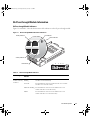
R9289bk1.book Page 1 Friday, February 18, 2005 1:30 PM
Dell™ PowerEdge™ 1855 Systems
Information Update
w w w. d e l l . c o m | s u p p o r t . d e l l . c o m
R9289bk1.book Page 2 Friday, February 18, 2005 1:30 PM
R9289bk1.book Page 1 Friday, February 18, 2005 1:30 PM
Dell™ PowerEdge™ 1855 Systems
Information Update
w w w. d e l l . c o m | s u p p o r t . d e l l . c o m
R9289bk1.book Page 2 Friday, February 18, 2005 1:30 PM
Notes, Notices, and Cautions
NOTE: A NOTE indicates important information that helps you make better use of your computer.
NOTICE: A NOTICE indicates either potential damage to hardware or loss of data and tells you how to avoid the
problem.
CAUTION: A CAUTION indicates a potential for property damage, personal injury, or death.
Abbreviations and Acronyms
For a complete list of abbreviations and acronyms, see "Glossary" in your User’s Guide.
____________________
Information in this document is subject to change without notice.
© 2005 Dell Inc. All rights reserved.
Reproduction in any manner whatsoever without the written permission of Dell Inc. is strictly forbidden.
Trademarks used in this text: Dell, the DELL logo, PowerEdge, PowerConnect, and Dell OpenManage are trademarks of Dell Inc.; Intel is a
registered trademark of Intel Corporation; Red Hat is a registered trademark of Red Hat, Inc.; Microsoft and Windows are registered trademarks
and Windows Server is a trademark of Microsoft Corporation.
Other trademarks and trade names may be used in this document to refer to either the entities claiming the marks and names or their products.
Dell Inc. disclaims any proprietary interest in trademarks and trade names other than its own.
February 2005
P/N R9289
Rev. A01
R9289bk1.book Page 3 Friday, February 18, 2005 1:30 PM
Contents
200–240 V System Power Requirements .
KVM Module
. . . . . . . . . . . . . . . . . . . . .
8
. . . . . . . . . . . . . . . . . . . . . . . . . . . . . . . . . . . .
8
Dell Diagnostics and KVM Module With KVM-Over-IP (ACI Port)
PS/2-Mouse Acceleration Support . . . . . . . . . . . . . . . .
Server Module Daughter Card Status Indicator .
Other Documents You May Need
. . . . . . . .
9
. . . . . . . . . . . . . . . . .
9
. . . . . . . . . . . . . . . . . . . . . . . .
300-GB Hard Drive Synchronizing and Rebuilding Durations .
. . . . . . . . .
Complete Hard Drive Synchronization Before Cold-Swapping the
Hard Drive . . . . . . . . . . . . . . . . . . . . . . . . . . . . . .
Environmental Data Sheets
10
. . . . . .
10
. . . . . . . . . . . . . . . . . . . . . . . . . . .
10
. . . . . . . . . . . . . . . . . . . . . . . . . .
10
I/O Module Indicator Update
Dell Remote Access Controller/Modular Chassis Version 1.1 Module .
General Information. . . . . . . . . . . . .
Important I/O Configuration Considerations
Redundancy Support . . . . . . . . . . . .
Guidelines for Installing Connectivity Modules.
. . . .
11
. . . . . . . . . . . . . . . .
. . . . . . . . . . . . . . . .
11
11
11
. . . . . . . . . . . . . . . .
12
. . . . . . . . . . . . . . . .
Red Hat Enterprise Linux (Version 3) Update 3 Operating
System Information . . . . . . . . . . . . . . . . . . . . .
. . . . . . . . . . .
Installation . . . . . . . . . . . . . . . . . . . . . . . . . .
Replacing a Gb Ethernet Daughter Card in a Server Module
GPM-Service Mouse Support . . . . . . . . . . . . . . . .
Tiered Broadcast Support
10
. . . . . . .
12
. . . . . . .
12
13
13
. . . . . . . . . . . . . . . . . . . . . . . . . . . .
13
Installing a Previously-Arrayed Hard Drive Into a SCSI-Mode
Server Module . . . . . . . . . . . . . . . . . . . . . . . . . .
. . . . . . .
. . . . . . . .
Unrecognizable SCSI/RAID Test Options in Dell OpenManage Server
Administrator Diagnostics . . . . . . . . . . . . . . . . . . . . . . . .
. . . .
13
14
Contents
3
R9289bk1.book Page 4 Friday, February 18, 2005 1:30 PM
Microsoft Windows 2000 Operating System Information .
.SIF File Installation Error . .
Service Pack Support . . . .
USB 2.0 Controller Support .
. . . . . . . . . . .
14
. . . . . . . . . . . . . . . . . . . . . . . .
. . . . . . . . . . . . . . . . . . . . . . . .
14
15
15
. . . . . . . . .
15
. . . . . . . . . . . . . . . . . . . . .
17
. . . . . . . . . . . . . . . . . . . . . . . .
Using a KVM Keyboard Sequence to Select Server Modules
Gb Pass-through Module Information .
Gb Pass-through Module Indicators . . . .
Gb Pass-through Module Link Negotiations
. . . . . . . . . . . . . . . .
17
18
. . . . . . . . . . . . . . . . .
18
. . . . . . . . . . . . . . . . . . . . . .
18
Enabling PXE on a Gb Ethernet Daughter Card
Baseboard Management Controller .
. . . . . . . . . . . . . . . .
IP Address-Related Items. . . . . . . . . . . . . .
Unsupported BMC Features and BMC Particulars .
BMC VLAN Tagging Support . . . . . . . . . . . .
. . . . . . . . . . . .
19
19
20
. . . . . . . . . . . . . . .
20
. . . . . . . . . . . . . . . . . . . . . .
20
Network Connectivity After Restart or Power-up .
Integrated Mirroring Configurations
. . . . . . . . . . . .
. . . . . . . . . . . .
COM1 Port Conflict After Installing the Microsoft Windows 2000 SP4 or
Windows Server 2003 Operating System . . . . . . . . . . . . . . . . .
. . .
21
. . . . . . . . . . . . . . .
21
. . . . . . . . . . . . . . . . . . . . . . . . .
21
Shutdown Procedure for Servicing a Hard Drive .
Acquiring the asset.com Utility
Red Hat Enterprise Linux AS (Version 3) Operating System Diskette
Drive Detection Messages . . . . . . . . . . . . . . . . . . . . . . .
. . . . .
21
. . . . . . . . . . . . . . . .
22
. . . . . . . . . . . . . . . . .
22
. . . . . . . . .
22
. . . .
23
. . . . . . . . .
23
USB CD Drive Online Read-Diagnostic Failures
KVM Switch Module Identification Indicator .
Booting to Microsoft MS-DOS Through Console Redirection
Creating a New Network Adapter Team Using the Procfg Application
Determining the Primary and Secondary Network Adapters .
4
Contents
R9289bk1.book Page 5 Friday, February 18, 2005 1:30 PM
Figures
Figure 1-1.
Gb Pass-through Module Indicators
and Features . . . . . . . . . . . .
. . . . . . . . .
17
Tables
Table 1-1.
Table 1-2.
Table 1-3.
Server Module Status Indicator Behavior for Gb
Ethernet Daughter Card . . . . . . . . . . . . .
. .
9
. . . .
9
. . . . . . . . .
17
Server Module Status Indicator Behavior for
Infiniband Daughter Card . . . . . . . . . .
Gb Pass-through Module Indicators
Contents
5
R9289bk1.book Page 6 Friday, February 18, 2005 1:30 PM
6
Contents
R9289bk1.book Page 7 Friday, February 18, 2005 1:30 PM
This document provides updated information for your system on the following topics:
•
200–240 V system power requirements
•
KVM module
•
Dell™ Diagnostics and KVM module with KVM-over-IP (ACI Port) PS/2-mouse acceleration
support
•
Server module daughter card status indicator
•
Other documents you may need
•
300-GB hard drive synchronizing and rebuilding durations
•
Completing hard drive synchronization before cold-swapping the hard drive
•
Environmental data sheets
•
I/O module indicator update
•
Dell Remote Access Controller/Modular Chassis version 1.1 module
–
General information
–
Important considerations when configuring I/O modules with DRAC/MC version 1.1
–
Redundancy support
•
Guidelines for installing connectivity modules
•
Red Hat® Enterprise Linux (version 3) update 3 operating system information
–
Installation
–
Replacing a Gb Ethernet daughter card
–
GPM-service mouse support
•
Tiered broadcast support
•
Precautions when installing a previously-arrayed hard drive into a SCSI-mode server module
•
Unrecognizable SCSI/RAID test options in Dell OpenManage™ Server Administrator
diagnostics
•
Microsoft® Windows® 2000 operating system information
–
.SIF file installation errors
–
Service pack support
–
USB 2.0 controller support
•
Using a KVM keyboard sequence to select server modules
•
Gb pass-through module information
•
Enabling PXE on a Gb Ethernet daughter card
•
Baseboard Management Controller (BMC)
•
Network connectivity after restart or power-up
Information Update
7
www.dell.com | support.dell.com
R9289bk1.book Page 8 Friday, February 18, 2005 1:30 PM
•
Integrated mirroring configurations
•
COM1 port conflict after installing the Microsoft Windows 2000 SP4 or
Windows Server™ 2003 operating system
•
Shutdown procedure for servicing a hard drive
•
Acquiring the asset.com utility
•
Red Hat Enterprise Linux AS (version 3) operating system diskette drive detection messages
•
USB CD drive online read-diagnostic failures
•
KVM switch module identification indicator
•
Booting to Microsoft MS-DOS® through console redirection
•
Creating a new network adapter team using the procfg application
•
Determining the primary and secondary network adapters
200–240 V System Power Requirements
NOTICE: The system requires 200–240 V to power up and operate.
Each system power supply requires 200–240 V input distributed from a PDU that is capable of
providing 1200 W or 2100 W, depending on the rating of your power supply.
The Dell-supplied power supply power cords can be plugged only into the PDU. However, a
standard 110-V power cord can mistakenly be connected to the 1200-W power supply receptacle
and to a 110-V source. When 110 V is supplied to a system that contains all 1200-W power
supplies, standby power is available and the fan, KVM, DRAC/MC, and the chassis indicators light
up and the DRAC/MC functions, but the chassis does not power up.
NOTE: Only the 1200-W power supply provides standby power if it is connected to a 110-V source—not
the 2100-W power supply. The DRAC/MC module becomes functional when stand-by power is available.
For more information about the system’s 200–240 V power requirements, see related articles at
support.dell.com.
KVM Module
The system’s User’s Guide and the Installation and Troubleshooting Guide refer to one KVM
module model as the KVM module with KVM-over-IP. The KVM module’s User’s Guide refers to
the module as the KVM module with analog console interface (ACI). The modules referred to in
these documents are the same device.
The KVM module provides an RJ-45 connector, called the ACI port, that only allows a dedicated
interface for connection to external KVM-over-IP switches. The RJ-45 ACI port does not provide a
serial connection for firmware upgrades and cannot be used for Ethernet management. See "KVM
Module" in the Installation and Troubleshooting Guide for more information about the KVM
module.
8
Information Update
R9289bk1.book Page 9 Friday, February 18, 2005 1:30 PM
Dell Diagnostics and KVM Module With KVM-Over-IP (ACI
Port) PS/2-Mouse Acceleration Support
Dell Diagnostics and the KVM module with KVM-over-IP (ACI port) firmware do not support PS/2
mouse acceleration. If the mouse slide-accelerator adjustment is set at high or fast, the mouse
movement may become erratic. Ensure that the mouse slide-accelerator adjustment remains set at
low or none.
Server Module Daughter Card Status Indicator
Table 2-2 in the Installation and Troubleshooting Guide and Table 1-2 in the User’s Guide provide
information on how the server module front-panel daughter card status indicator behaves if a Fibre
Channel daughter card is installed. Table 1-1 provides information about how that indicator
behaves if a Gb Ethernet daughter card is installed.
Table 1-1. Server Module Status Indicator Behavior for Gb Ethernet Daughter Card
Indicator
Icon
Activity Indicator
Indicator Code
Daughter card
status indicator
I/O
Off
A link does not exists.
Green
A link exists.
Green blinking
Activity on the Gb Ethernet daughter card.
Table 1-2 provides information about how this indicator behaves if an Infiniband daughter card is
installed.
Table 1-2.
Server Module Status Indicator Behavior for Infiniband Daughter Card
Indicator
Icon
Activity Indicator
Indicator Code
Daughter card
status indicator
I/O
Off
Infiniband daughter card is not installed.
Green
Infiniband daughter card is present, but its driver has not yet
loaded.
Green blinking
Infiniband daughter card is present, its driver has loaded,
and daughter-card data transfers are occurring.
Information Update
9
R9289bk1.book Page 10 Friday, February 18, 2005 1:30 PM
www.dell.com | support.dell.com
Other Documents You May Need
Dell continues to offer new types of connectivity modules for your system and provides
documentation on how to set up and use them. The documentation for a particular module is
included with the module product or is available at support.dell.com.
NOTE: Ensure that you also refer to support.dell.com for any updates to the documentation that you
received with your module.
300-GB Hard Drive Synchronizing and Rebuilding Durations
Because of the large disc size of 300-GB hard drives, expect longer synchronizing and rebuilding
durations than smaller hard-drive disc sizes. A 300-GB hard drive installed in a system with very low
or no I/O activity requires at least 22 hours to synchronize or rebuild. A 300-GB hard drive installed
in a system with high I/O activity requires up to 51 hours to synchronize or rebuild.
Complete Hard Drive Synchronization Before Cold-Swapping
the Hard Drive
If you install and start the synchronization of a hard drive, ensure that you allow the
synchronization to complete. Otherwise, if that hard drive is cold-swapped into another RAID or a
non-RAID system, the hard drive will not be recognized.
NOTE: A hard drive that has not completed synchronization can be hot-swapped into another RAID or
non-RAID system without any recognition problems.
Environmental Data Sheets
For additional information about environmental measurements for specific system configurations,
see dell.com/environment_datasheets. The system is not for use in an office environment.
I/O Module Indicator Update
An I/O module's green system/diagnostic indicator is off when the module is properly operating or
is off and blinks when the module is not properly operating. See "Indicators, Codes, and Messages"
in your Installation and Troubleshooting Guide for more information about I/O modules.
10
Information Update
R9289bk1.book Page 11 Friday, February 18, 2005 1:30 PM
Dell Remote Access Controller/Modular Chassis Version 1.1
Module
General Information
If you have the Dell Remote Access Controller/Modular Chassis (DRAC/MC) version 1.1 module
installed, ensure that you read that product’s readme.txt file. It contains updated information
including how that module version affects system indicator behavior in certain conditions.
Important I/O Configuration Considerations
CAUTION: Data loss can result if you perform certain actions on a DRAC/MC 1.1 system in which the
I/O bays have not been configured to fully support the operation of the version 1.1 firmware.
Specifically, bay 2 should have an I/O module installed only if an identical module is present in bay 1,
and bay 4 should have an I/O module installed only if an identical module is present in bay 3. Except in
these cases (or in a case where you temporarily need to swap a failed I/O module in bay 1 or 3), bays 2
and 4 should be unoccupied.
Unless your system is configured accordingly, do not perform any of the following actions:
•
Upgrade DRAC/MC firmware
•
Issue a software reset command for a DRAC/MC, such as racadm racreset
•
Reseat a DRAC/MC module
•
Cause a DRAC/MC failover event, such as removing the network cable from the primary DRAC/MC
Performing any of these actions will power off and stop traffic on the bay 2 or bay 4 I/O module, resulting in
data loss.
When initiated, the DRAC/MC version 1.1 firmware algorithm must find a module in bay 1 before
bay 2 and a module in bay 3 before bay 4. Otherwise, the module in bay 2 or bay 4 will be powered
off if you perform a firmware upgrade procedure on the DRAC/MC, cause a DRAC/MC failover, or
reset the DRAC/MC.
See the Dell Remote Access Controller/Modular Chassis Version 1.1 User's Guide at
support.dell.com for more information about configuring your DRAC/MC system.
Redundancy Support
If you are adding the DRAC/MC version 1.1 module to a system to enable redundancy, the
firmware levels of both DRAC/MC modules must be version 1.1. If the DRAC/MC module
currently in the system is version 1.0, you must upgrade the firmware of the current module to
version 1.1 prior to installing the new DRAC/MC version 1.1 module.
NOTE: A DRAC/MC module’s firmware version is displayed on its web-based GUI or by typing the
command getsysinfo or racadm getsysinfo.
NOTE: DRAC/MC version 1.1 firmware uses a different MAC address than the MAC address reported by
DRAC/MC version 1.0 firmware. Therefore, a DHCP-assigned dynamic IP address may change after
updating to the DRAC/MC version 1.1 firmware.
Information Update
11
R9289bk1.book Page 12 Friday, February 18, 2005 1:30 PM
www.dell.com | support.dell.com
See the Dell Remote Access Controller/Modular Chassis Version 1.1 User's Guide at
support.dell.com for more information about firmware updates and installing redundant
DRAC/MC modules. This guide also provides complete instructions on how to set up and operate
that version of the module.
Guidelines for Installing Connectivity Modules
When inserting connectivity modules into the system’s back-panel I/O bays, follow these
guidelines:
NOTE: See your Installation and Troubleshooting Guide for the I/O-bay numbering sequence.
•
Insert a connectivity module into I/O bay 1 before installing a connectivity module into I/O
bay 2.
I/O bays 1 and 2 support only Gb Ethernet switch or pass-through modules. Ensure that the
Ethernet modules installed in I/O bays 1 and 2 are of the same type.
•
Insert a connectivity module into I/O bay 3 before installing a connectivity module into I/O
bay 4.
Ensure that the connectivity modules installed in I/O bays 3 and 4 are of the same type.
For more information, see the Dell Remote Access Controller/Modular Chassis Version 1.1 User's
Guide at support.dell.com.
Red Hat Enterprise Linux (Version 3) Update 3 Operating
System Information
Installation
Newer Intel® processors have an XD bit-enabled feature that allows an operating system to reserve
a segment of memory to store code in a non-executable environment. Under certain circumstances,
this feature can cause the installation of the Red Hat Enterprise Linux (version 3) Update 3
operating system from the Dell OpenManage CD to fail.
To disable XD-bit support to prevent this installation failure, add switch noexec=off to the
/etc/grub.conf file as shown in the following example:
kernel /vmlinuz-2.4.21-20.EL ro root=LABEL=/ noexec=off
If an EM64T kernel is being used, also include the noexec32=off parameter on the kernel line
as shown in the following example:
kernel /vmlinuz-2.4.21-20.EL ro root=LABEL=/ noexec=off noexec32=off
12
Information Update
R9289bk1.book Page 13 Friday, February 18, 2005 1:30 PM
Replacing a Gb Ethernet Daughter Card in a Server Module
If you replace a Gb Ethernet daughter card in a server module running the Red Hat Enterprise
Linux (version 3) update 3 operating system, you must assign the new card’s MAC address. Linux
initially creates the ifcfg-ethn file, where n is the device ID, based on the original card’s device ID.
If another Gb Ethernet daughter card with a different MAC address is installed, Linux does not
automatically update the file. The MAC address in the ifcfg-ethn file is located in the hwaddr line.
GPM-Service Mouse Support
For a mouse to correctly function in the GPM service on a system running the Red Hat Enterprise
Linux (version 3) update 3 operating system, the mouse must be recognized by the operating
system. When using a mouse connected to the KVM, it is possible that the mouse being reported
to the operating system is different than the actual mouse attached. This may result in mouse
movement generating erratic movement or potentially random text on the command line. To
correct this, run redhat-config-xfree86 to initialize the mouse, and then use redhat-config-mouse
to install a generic three-button mouse driver for the presently-installed mouse.
Tiered Broadcast Support
If the KVM module is tiered from an external KVM switch to the internal KVM switch, keyboard
and mouse broadcast functionality is not supported. Turn off broadcast to external KVM-switch
ports that have a Dell-integrated KVM switch connected to them.
Installing a Previously-Arrayed Hard Drive Into a SCSI-Mode
Server Module
A hard drive previously installed in a RAID configuration contains partial segments of information
referred to as "meta-data." If you hot-install a hard drive that contains meta-data into a SCSI-mode
server module, its array may appear as degraded after the server module is rebooted.
CAUTION: Do not attempt to rebuild the degraded array in a SCSI-mode server module. The server
module can accommodate up to two hard drives, one of which is the primary physical boot hard drive.
Rebuilding the array could result in loss of data from the primary hard drive.
To remove the meta-data from the replacement hard drive, perform the following steps:
1 Back up all data onto the replacement hard drive.
2 Restart the server module and press <Ctrl><m>.
3 Change the degraded array properties from mirror to SCSI mode by selecting NO as the
Mirror option.
Information Update
13
www.dell.com | support.dell.com
R9289bk1.book Page 14 Friday, February 18, 2005 1:30 PM
Unrecognizable SCSI/RAID Test Options in Dell OpenManage
Server Administrator Diagnostics
The Diagnostics Service of Dell OpenManage Server Administrator 1.8 and newer may not display
test options properly for SCSI or RAID tests on non-English Microsoft Windows or Red Hat
Enterprise Linux operating systems. When selecting a SCSI or RAID controller in the Server
Administrator web interface, the applicable tests in the right margin may be displayed only as
TEST1_NAME, TEST2_NAME... instead of the actual translated test name. Test results will also
display in a terse internal string name instead of a detailed description.
Use the Server Administrator command-line interface (CLI) on non-English operating systems for
SCSI and RAID controllers and devices. Use the omreport storage scsidevdiag -? and omreport
storage raidctrl -? CLI commands to get more information about running these diagnostics. See
the Dell OpenManage Server Administrator Version 1.x Command Line Interface User's Guide for
more information about the CLI commands.
NOTE: Server Administrator CLI output is in English only.
Microsoft Windows 2000 Operating System Information
.SIF File Installation Error
NOTE: Updating to the newest server module BIOS revision eliminates the installation error described in
this section.
The Microsoft Windows 2000 operating system installation process may occasionally be unable to
detect a mouse or keyboard during its plug-and-play detection search and display the following
error message:
Windows Server Setup
The following value in the .SIF file used by setup is corrupted
or missing
Setup cannot continue. To quit setup, press F3.
This may occur if a keyboard and mouse are not connected to the server module’s front-panel KVM
custom cable, the KVM is used to switch to another server module during the installation, the
installation is being performed unattended, or Windows 2000 is being installed from the Dell
Server Assistant CD.
If the error occurs in an attended installation, reboot the server module to restart the installation,
and then press <F3> when prompted to continue. Do not disconnect the keyboard and mouse
KVM custom cable from the server module’s front panel or switch to another server module until
after the text-mode portion of the installation is complete.
NOTE: This error can occur only during the text-mode portion of the operating system installation.
14
Information Update
R9289bk1.book Page 15 Friday, February 18, 2005 1:30 PM
If the error occurs in an unattended installation, specify the keyboard type as "RETAIL" to
prevent the installation from requiring a detection. To specify a keyboard type, modify the
unattended.txt or winnt.sif installation file as shown in the following English-language string
example:
# English
[KeyBoardDrivers]
"XT, AT, or Enhanced Keyboard (83-104 keys)" = "RETAIL"
Service Pack Support
Only the Microsoft Windows 2000 operating system with SP4 or higher is supported on the system.
Dell recommends using Windows 2000 media with integrated or slipstreamed SP4 or higher be
installed for the initial operating system load rather than updating an earlier version of
Windows 2000 with an SP4 or higher patch.
USB 2.0 Controller Support
NOTE: Use of any USB 2.0-enabled CD-ROM drive to install the Windows 2000 or Windows 2003 family of
Enterprise products is not supported, and the installation may not complete properly. Only the Dellprovided CD-ROM drive is supported for operating system installation.
The system’s USB controller supports USB 1.1 and 2.0. The Microsoft Windows 2000 SP4 and
higher operating system supports USB 2.0. A red "X" appears on the USB controller device in
Device Manager on versions of Windows 2000 prior to SP4 because those versions do not contain
USB 2.0 drivers. If you are updating a previous installation of Windows 2000 to SP4, perform the
following steps to update the driver:
1 Uninstall the USB controller device in the Universal Serial Bus controllers list in
Device Manager.
2 Right-click Universal Serial Bus controllers in Device Manager.
3 Select Scan for hardware changes to rediscover the USB controller device.
Using a KVM Keyboard Sequence to Select Server Modules
NOTE: This section does not pertain to the KVM module with KVM-over-IP (ACI port). Server module
selection with that KVM module type is performed by pressing <PrtScn> and using its on-screen GUI.
To prevent call traces when using a keyboard attached to the back-panel KVM module to select
server modules running the Red Hat Enterprise Linux operating system, use the following keyboard
sequence:
<Scroll Lock>, <Left Alt>, <Scroll Lock>, <number key>, and <Enter>
For example, to select Linux-based server module 2, press <Scroll Lock>, <Left Alt>,
<Scroll Lock>, <2>, and <Enter>.
Information Update
15
R9289bk1.book Page 16 Friday, February 18, 2005 1:30 PM
www.dell.com | support.dell.com
To select server modules running a Microsoft Windows operating system, use the following
keyboard sequence:
<Scroll Lock>, <Shift>, <Scroll Lock>, <number key>, and <Enter>
For example, to select Windows-based server module 2, press <Scroll Lock>, <Shift>,
<Scroll Lock>, <2>, and <Enter>.
NOTE: If you are installing the Microsoft Windows 2000 operating system, see "Microsoft Windows 2000
Operating System Information" in this document for important information about switching server
modules while installing that operating system.
NOTE: When selecting the server module number, use the number keys on the top row of the keyboard
and not the key pad numbers.
NOTE: Ensure that you turn off <Scroll Lock> after selecting a server module. Otherwise, the keyboard
does not accept keystrokes.
For more information about the KVM module, see "KVM Modules" in the User’s Guide.
16
Information Update
R9289bk1.book Page 17 Friday, February 18, 2005 1:30 PM
Gb Pass-through Module Information
Gb Pass-through Module Indicators
Figure 1-1 and Table 1-3 describe the functions of the indicators on the Gb pass-through module.
Figure 1-1. Gb Pass-through Module Indicators and Features
link indicator
activity indicator
status indicator
activity indicator
link indicator
9
7 5 3 1
10
8 6 4 2
Table 1-3. Gb Pass-through Module Indicators
Indicator Type
Activity
Indicator
Link
Green/amber
indicator/activity blinking
indicator
Green/off
Indicator Code
The Gb Ethernet connector is linked to the server module
and there is network activity.
The Gb Ethernet connector is linked to the server module
and there is no network activity.
Off/amber blinking The Gb Ethernet connector is not linked to the server
module and there is network activity.
Off/off
The Gb Ethernet connector is not linked to the server
module and there is no network activity.
Information Update
17
R9289bk1.book Page 18 Friday, February 18, 2005 1:30 PM
www.dell.com | support.dell.com
Table 1-3. Gb Pass-through Module Indicators (continued)
Indicator Type
Activity
Indicator
Indicator Code
Status indicator
Off
Module is operating correctly.
Green blinking
Module has an error or is not configured correctly. Ensure
that the connection between the external switch and the
module is properly configured.
Gb Pass-through Module Link Negotiations
A Gb Pass-through module external port negotiates a link with an external device whether a server
module is installed or not. This is because the Gb pass-though module uses the SerDes interface
for internal connectivity to the server modules. The following items describe normal behavior of
the Gb pass-though module when a cable is connected from an external port on the module to an
external switch.
•
A link is displayed at the external switch and at the Gb Pass-through module if a server
module is installed or a Gb Ethernet daughter card is installed in the server module.
•
A link is displayed at the external switch, but not at the Gb Pass-through module if a server
module is not installed or a Gb Ethernet daughter card is not installed in the server module.
•
A Gb Pass-through module installed in I/O bay 1 or 2 will show a link at the external switch if
no server module is installed.
•
A Gb Pass-through module installed in I/O bay 3 or 4 will show a link if no Gb Ethernet
daughter card is installed in the server module.
Enabling PXE on a Gb Ethernet Daughter Card
To enable PXE on a server module’s Gb-Ethernet daughter card, locate the Intel IBAUtil utility
(version 3.04.04.00 or later). This utility is available as part of the DOS utilities for network
adapters available at support.dell.com. Follow the directions provided in the utility package to
enable PXE.
Baseboard Management Controller
This section provides updated information regarding the BMC. For detailed information regarding
the BMC, see the Dell OpenManage Baseboard Management Controller User’s Guide and the Dell
PowerConnect 5316M CLI Reference Guide.
18
Information Update
R9289bk1.book Page 19 Friday, February 18, 2005 1:30 PM
IP Address-Related Items
The following items are BMC updates concerning its IP address:
•
The BMC IP address and the host port 1(the first one) IP address must be set to the same
value. This means that if the host is using DHCP, the BMC LAN channel must be turned off.
•
Ensure that the gateway IP address is set to the correct subnet and the IP address is correct
when routing packets to the BMC. The BMC will properly respond to routed packets if only
the IP address is correct, but some packets may be lost if the gateway IP address is incorrect.
•
Any host application that monitors ports 623 and 644 cannot be executed from port 1 (the
first one) of a server module. If you attempt this, the network packets will be sent to the BMC
instead of the host. Use port 2 instead.
Unsupported BMC Features and BMC Particulars
The following items describe BMC particulars and features that are not supported by the BMC on
this system.
•
The IPMI Shell does not allow a user with administrator-level BMC user privileges to set and
change user privileges.
•
The server module does not have an external serial connector; therefore, Terminal and Basic
mode are not supported through a serial port for out-of-band (IPMI) management.
NOTE: Console redirection can be set to the DRAC/MC module if use of its serial port is desired.
•
Alerts (PET), Platform Event Filters (PEF), and DHCP are not supported as there are no alert
destination or IP Source options in the BMC setup.
•
To prevent heavy ARP request traffic to the BMC, the BMC does not receive any ARP
requests as they are routed only to the host.
•
The BMC sends gratuitous ARPs every 10 seconds to allow a remote host to discover the
BMC if the host’s operating system is not communicating.
•
The server module’s front-panel power and KVM buttons are directly connected to the BMC.
If the BMC program becomes misconfigured or corrupt, the power button may not operate.
•
Do not use the keyboard sequence to switch server modules or turn off the server module
when updating the BMC firmware. Otherwise, the update may fail. If this does occur, restart
the update.
Information Update
19
R9289bk1.book Page 20 Friday, February 18, 2005 1:30 PM
www.dell.com | support.dell.com
BMC VLAN Tagging Support
The BMC supports VLAN (Virtual LAN) tagging for network traffic. VLANs are configured on the
network switch and are given a VLAN ID or tag. Ports on the switch can belong to one or more
VLAN and can have one of the following VLAN settings:
•
Tagged — The packets coming out of the switch port contain the VLAN tag. In this case you
should enable VLAN tags on the BMC and set the BMC VLAN tag (or ID) to the same value
as the switch port. Otherwise the BMC will not respond to incoming network traffic. Note
that setting a VLAN tag on the BMC also causes the BMC to insert the VLAN tag to all
outgoing network packets.
•
Untagged — The packets coming out of the switch port do not contain the VLAN tag. In this
case you should disable VLAN tags on the BMC. By default, VLAN tags are disabled on the
BMC.
NOTE: See the Dell PowerConnect 5316M CLI Reference Guide for more information about using
the VLAN commands.
Network Connectivity After Restart or Power-up
After the server chassis is powered-up or the PowerConnect™ 5316M Ethernet Switch Module
(ESM) is rebooted or power cycled, the ESM will require approximately one minute and forty-five
seconds to become fully operational. In addition, the ESM may require up to sixty seconds to
establish the links to external Ethernet devices if the spanning tree protocol is enabled on the
external ports of the ESM. See the Dell PowerConnect 5316M Systems Getting Started Guide for
information on how to determine when the ESM is fully operational.
Integrated Mirroring Configurations
The following items provide updates for setting up and using integrated mirroring:
•
The hard-drive status indicator does not display any status information until after the
operating system driver initialization has occurred. To check for status information of a hard
drive prior to operating system load, use <Ctrl><m> during POST. See the Dell PowerEdge
Expandable RAID Controller 4/IM User’s Guide for more information. During normal
operation, the status indicator is off.
NOTE: The hard-drive activity indicator functions normally before and after the operating system
driver initialization.
NOTICE: If you use a drive with existing data, the data will be cleared before the hard drive is added to a
mirror.
20
•
It is recommended that any replacement drives should be blank and not previously
configured.
•
It is recommended that you replace hard drives in an integrated-mirror configuration with
drives of the same capacity.
Information Update
R9289bk1.book Page 21 Friday, February 18, 2005 1:30 PM
•
After removing a hard drive in a hot-pluggable environment, wait at least 30 seconds prior to
installing the new hard drive.
COM1 Port Conflict After Installing the Microsoft
Windows 2000 SP4 or Windows Server 2003 Operating
System
If the Microsoft Windows 2000 SP4 or Windows Server 2003 operating system is installed and
console redirection is enabled, a yellow exclamation mark conflict will appear by COM1 in the
Device Manager. This is because the operating system attempts to assign a COM1, but the server
module physically does not have a serial port. To prevent the conflict from returning, delete the
COM1 port in Device Manager.
Shutdown Procedure for Servicing a Hard Drive
NOTE: This section applies only to situations where the server module must be powered down to
service a hard drive. In many situations, the hard drive can be serviced while the server module
powered on.
If you need to power off the server module to service a hard drive, wait 30 seconds after the server
module’s power indicator turns off before removing the hard drive. Otherwise, the hard drive may
not be recognized by the PERC 4/IM after the hard drive is reinstalled and the server module is
powered on again.
Acquiring the asset.com Utility
The asset.com utility is not located in the Service Mode section of the Dell OpenManage Server
Assistant CD. To acquire the utility, use the Server Assistant CD to create a bootable diskette and
the utility is created on that diskette. The asset.com utility will be available in the Service Mode
section in future releases of the Server Assistant CD.
Red Hat Enterprise Linux AS (Version 3) Operating System
Diskette Drive Detection Messages
When the Red Hat Enterprise Linux AS (version 3) operating system boots, it detects the USB
controller and attempts to load a USB diskette drive. If the optional USB diskette drive is not
connected to the server module’s front-panel custom cable, the operating system attempts to load
the diskette drive five times and displays informative messages on the screen. After five attempts
with no USB diskette drive detected, the messages stop appearing. If a USB device is removed or
inserted, the detection attempts begin again. This is a normal operating system behavior.
Information Update
21
R9289bk1.book Page 22 Friday, February 18, 2005 1:30 PM
www.dell.com | support.dell.com
USB CD Drive Online Read-Diagnostic Failures
If the optional USB CD drive fails the online read-diagnostics and becomes inaccessible on a server
module running the Microsoft Windows 2000 SP4 or the Windows Server 2003 operating system
with PAE enabled, the failure may be caused by having the data transfer length set at 64 KB or
higher. A patch will be available at support.microsoft.com in the future. Until the patch is
available, reduce the data transfer length to less than 64 KB.
KVM Switch Module Identification Indicator
After a back-panel KVM switch module is replaced or hot-swapped, its system identification
indicator may start flashing. If this occurs, press the identification button on the front of the
system to reset the identification indicator.
Booting to Microsoft MS-DOS Through Console Redirection
If Microsoft MS-DOS briefly toggles from text mode to video mode, a console redirection session
may be terminated. When booting to MS-DOS, a Microsoft Windows 9x video-mode splash screen
is briefly displayed before the c:\ prompt appears. To disable the splash screen in an MS-DOS
session using Notepad text editor, perform the following steps:
1 Open an MS-DOS session.
2 Type attrib -r -s -h C:\MSDOS.SYS and press <Enter>.
3 Type notepad C:\MSDOS.SYS and press <Enter>.
Notepad text editor opens.
4 Scroll through the command lines and locate line LOGO=1 and change the 1 to 0.
If the LOGO command line is not present, add the line by typing LOGO=0 immediately below
the line [Options].
5 Click the File menu, click Save, and then close Notepad.
6 At the MS-DOS prompt, type attrib +r +s +h C:\MSDOS.SYS and press <Enter>.
7 Close the MS-DOS window.
22
Information Update
R9289bk1.book Page 23 Friday, February 18, 2005 1:30 PM
Creating a New Network Adapter Team Using the Procfg
Application
An issue exists if the procfg application is used to create a new network adapter team. If both
network adapters are added to the team, the procfg application switches the MAC addresses of the
two adapters making the team unusable by the operating system. The affected driver revisions are
listed below.
•
Procfg 2.2.19
•
E1000 5.3.19-1
•
Ians 3.4.2a-2.4.21_4.EL
Future releases of these drivers will not be affected.
Two workarounds exist until the new drivers are available:
•
Add one network adapter to the team, save the team information, and then add the second
adapter.
•
Modify the /etc/procfg/team name file, where team name is the name of the new network
adapter team, and correct the MAC addresses.
Determining the Primary and Secondary Network Adapters
During a Microsoft Windows 2000 or Windows Server 2003 operating system installation, the
operating system enumerates physical network adapters, but may list them in random order. This
can cause confusion when setting up and testing a network adapter team for failover/failback. This
may also cause misunderstandings as to which cable is the primary or the secondary network
adapter team member and cause unexpected team behavior when a cable is disconnected or
connectivity is interrupted.
To help determine the identities of physical network adapters, right-click and rename the adapters
in Network Connections in the Control Panel, use the ipconfig /all command to note the IP-toMAC address assignments of the adapters, and then use the IP addresses to locate the adapters in
Network Connections.
For a system with integrated network adapters, LOM1 has the lowest MAC address. The link status
indicators can also be used to externally identify the adapters to the system. Additionally, an
integrated network adapter’s MAC address is listed in the System Setup program.
NOTE: Occasionally during an operating system installation, the network adapters may be incorrectly
assigned and cause IP address conflict messages to appear during boot. If this occurs, use the
procedures listed above to correctly assign the network adapters.
Information Update
23
www.dell.com | support.dell.com
R9289bk1.book Page 24 Friday, February 18, 2005 1:30 PM
24
Information Update
R9289bk1.book Page 1 Friday, February 18, 2005 1:30 PM
R9289bk1.book Page 2 Friday, February 18, 2005 1:30 PM
Printed in the U.S.A.
R9289bk1.book Page 1 Friday, February 18, 2005 1:30 PM
R9289bk1.book Page 2 Friday, February 18, 2005 1:30 PM
Printed in Malaysia.
R9289bk1.book Page 1 Friday, February 18, 2005 1:30 PM
R9289bk1.book Page 2 Friday, February 18, 2005 1:30 PM
Printed in Ireland.
R9289bk1.book Page 1 Friday, February 18, 2005 1:30 PM
R9289bk1.book Page 2 Friday, February 18, 2005 1:30 PM
Printed in China.
Printed on recycled paper.


![SamsungProdBulletin_211_4_4x_Software_Release[1]](http://vs1.manualzilla.com/store/data/005825179_1-598976db56b1ef1012f4b9b7fb2b917f-150x150.png)