1
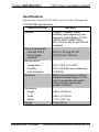
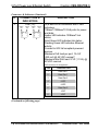
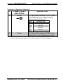
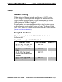
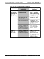
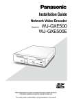
Crestron CEN-SW-POE-5
5-Port Power over Ethernet Switch
Installation Guide
This document was prepared and written by the Technical Documentation department at:
Crestron Electronics, Inc.
15 Volvo Drive
Rockleigh, NJ 07647
1-888-CRESTRON
All brand names, product names and trademarks are the property of their respective owners.
©2008 Crestron Electronics, Inc.
Crestron CEN-SW-POE-5
5-Port Power over Ethernet Switch
Contents
5-Port Power over Ethernet Switch: CEN-SW-POE-5
1
Introduction ............................................................................................................................... 1
Features and Functions ................................................................................................ 2
Specifications .............................................................................................................. 3
Physical Description.................................................................................................... 4
Industry Compliance ................................................................................................. 10
Setup ........................................................................................................................................ 11
Network Wiring......................................................................................................... 11
Supplied Hardware .................................................................................................... 11
Installation ................................................................................................................. 12
Hardware Hookup ..................................................................................................... 14
Problem Solving ...................................................................................................................... 15
Troubleshooting......................................................................................................... 15
Reference Documents................................................................................................ 17
Further Inquiries ........................................................................................................ 17
Future Updates .......................................................................................................... 17
Return and Warranty Policies .................................................................................................. 18
Merchandise Returns / Repair Service ...................................................................... 18
CRESTRON Limited Warranty................................................................................. 18
Installation Guide – DOC. 6694A
Contents • i
Crestron CEN-SW-POE-5
5-Port Power over Ethernet Switch
5-Port Power over Ethernet
Switch: CEN-SW-POE-5
Introduction
The CEN-SW-POE-5 is a five-port unmanaged Ethernet switch designed
to provide standards-based IEEE 802.3af Power over Ethernet (PoE)
capability from four ports. The CEN-SW-POE-5 powers Crestron
802.3af-compliant powered devices such as the CEN-WAP-ABG-1G
wireless access point. In addition, the CEN-SW-POE-5 can power thirdparty 802.3af-compliant powered devices. Using the CEN-SW-POE-5,
a separate power supply is not needed at the location of each
powered device.
The CEN-SW-POE-5 also provides an uplink port that connects to a
network hub or switch.
NOTE: The uplink port does not provide PoE capability.
Installation Guide – DOC. 6694A
5-Port Power over Ethernet Switch: CEN-SW-POE-5 • 1
5-Port Power over Ethernet Switch
Crestron CEN-SW-POE-5
Features and Functions
•
•
•
•
Four 10BaseT/100BaseTX 802.3af PoE ports
One 10BaseT/100BaseTX uplink port
Autonegotiation of data transmission rate and duplex mode
Auto MDI/MDI-X (Medium Dependent Interface/Medium
Dependent Interface Crossover) operation
• 3.2 Gbps switching fabric
• Wall and rack mountable design
Four 10BaseT/100BaseTX 802.3af PoE Ports
Using 802.3af PoE technology, each of four 10BaseT/100BaseTX ports
can provide power to an 802.3af-compliant Ethernet device using the
same cable as that used for the network connection. In addition, PoE
technology provides built-in protection to prevent damage from occurring
when power is applied to non-PoE devices.
Auto MDI/MDI-X Operation
A straight-through or crossover cable can be used to connect to any port
on the CEN-SW-POE-5. Using auto MDI/MDI-X operation, the port
automatically detects the cable type that is used.
2 • 5-Port Power over Ethernet Switch: CEN-SW-POE-5
Installation Guide – DOC. 6694A
Crestron CEN-SW-POE-5
5-Port Power over Ethernet Switch
Specifications
Specifications for the CEN-SW-POE-5 are listed in the following table.
CEN-SW-POE-5 Specifications
SPECIFICATION
Ethernet
10BaseT/100BaseTX, autoswitching, auto-negotiating, autodiscovery, full/half duplex; TCP/IP,
UDP/IP, DHCP, IGMP; IEEE
802.3, 802.3u, 802.3x, and 802.3af
compliant
Power Requirements
CEN-SW-POE-5
Power Supply
(included)
Environmental
Temperature
Humidity
Heat Dissipation
Enclosure
Dimensions
Height
Width
Depth
Weight
Installation Guide – DOC. 6694A
DETAILS
60 VA (1.25 A) @ 48 VDC
100-240 VAC, 50/60 Hz
32º to 104ºF (0º to 40ºC)
10% to 90% RH (non-condensing)
10 BTU/Hr
Metal surface mount box with two
integral mounting flanges, 19” EIA
rack-rail mountable (one sided),
wall-mountable, black matte
powder coat finish
5.06 in (12.86 cm)
4.66 in (11.82 cm)
1.17 in (2.97 cm)
13 oz (381 g)
5-Port Power over Ethernet Switch: CEN-SW-POE-5 • 3
5-Port Power over Ethernet Switch
Crestron CEN-SW-POE-5
Physical Description
This section provides information on the connections and indicators
available on your CEN-SW-POE-5.
CEN-SW-POE-5 Physical View
4 • 5-Port Power over Ethernet Switch: CEN-SW-POE-5
Installation Guide – DOC. 6694A
Crestron CEN-SW-POE-5
5-Port Power over Ethernet Switch
CEN-SW-POE-5 Overall Dimensions
Front View
5.06 in
(12.86 cm)
3.62 in
(9.18 cm)
Bottom View
1.17 in
(2.97 cm)
4.66 in
(11.82 cm)
Installation Guide – DOC. 6694A
5-Port Power over Ethernet Switch: CEN-SW-POE-5 • 5
5-Port Power over Ethernet Switch
Crestron CEN-SW-POE-5
CEN-SW-POE-5 Connectors & Indicators
1
2
3
4
5
6 • 5-Port Power over Ethernet Switch: CEN-SW-POE-5
Installation Guide – DOC. 6694A
Crestron CEN-SW-POE-5
5-Port Power over Ethernet Switch
Connectors & Indicators
#
1
CONNECTORS &
INDICATORS
Uplink
AMBER
LED
8
GREEN
LED
1
DESCRIPTION
(1) 8-wire RJ-45 connector with 2 LED
indicators;
10BaseT/100BaseTX Ethernet port;
Amber LED indicates 100BaseT link
status;
Solid Green LED indicates link status;
Flashing Green LED indicates Ethernet
activity.
Connects to network hub or switch.
Uplink Connector Pin Assignments
PIN
2
PoE
DESCRIPTION
1
Data Pair 1
2
Data Pair 1
3
Data Pair 2
4
No Connection
5
No Connection
6
Data Pair 2
7
No Connection
8
No Connection
(4) Green LEDs, indicate that the
corresponding PoE port is providing power
to an 802.3af-compliant device.
(Continued on following page)
Installation Guide – DOC. 6694A
5-Port Power over Ethernet Switch: CEN-SW-POE-5 • 7
5-Port Power over Ethernet Switch
Crestron CEN-SW-POE-5
Connectors & Indicators (Continued)
#
CONNECTORS &
INDICATORS
DESCRIPTION
PoE (1-4)
(4) 8-wire RJ-45 connectors with 2 LED
indicators;
10BaseT/100BaseTX PoE ports for power
and data;
Amber LED indicates 100BaseT link
status;
Solid Green LED indicates link status;
Flashing Green LED indicates Ethernet
activity.
Connect to 802.3af-compliant powered
devices.
Maximum PoE load per port: 15.4 W
(350 mA) @ 48 VDC nominal*;
Maximum total PoE load: 57 W (1.19 A) @
48 VDC nominal.
3
AMBER
LED
8
GREEN
LED
1
AMBER
LED
8
GREEN
LED
1
PoE Connector Pin Assignments
PIN
DESCRIPTION
1
Data Pair 1
2
Data Pair 1
3
Data Pair 2
4
+VDC
5
+VDC
6
Data Pair 2
7
-VDC
8
-VDC
(Continued on following page)
8 • 5-Port Power over Ethernet Switch: CEN-SW-POE-5
Installation Guide – DOC. 6694A
Crestron CEN-SW-POE-5
5-Port Power over Ethernet Switch
Connectors & Indicators (Continued)
#
CONNECTORS &
INDICATORS
DESCRIPTION
4
48VDC
(1) 4-pin power connector, 48 VDC power
input (external power supply included).
5
*
1
3
2
4
Power
48VDC Connector Pin Assignments
PIN
DESCRIPTION
1
+48 VDC
2
+48 VDC
3
Ground
4
Ground
(1) Yellow LED, indicates 48 VDC power
supplied from the external power supply.
Due to the inherent voltage drop over copper wire, a maximum of 12.9 W is guaranteed to be
received by the PoE powered device over a cable run length of 328 feet (100 meters).
Installation Guide – DOC. 6694A
5-Port Power over Ethernet Switch: CEN-SW-POE-5 • 9
5-Port Power over Ethernet Switch
Crestron CEN-SW-POE-5
Industry Compliance
This product is Listed to applicable UL Standards and requirements by
Underwriters Laboratories Inc.
(E312979)
As of the date of manufacture, the CEN-SW-POE-5 has been tested and
found to comply with specifications for CE marking and standards per
EMC and Radiocommunications Compliance Labelling.
NOTE: This device complies with part 15 of the FCC rules. Operation is
subject to the following two conditions: (1) this device may not cause
harmful interference and (2) this device must accept any interference
received, including interference that may cause undesired operation.
This equipment has been tested and found to comply with the limits for a
Class B digital device, pursuant to part 15 of the FCC Rules. These limits
are designed to provide reasonable protection against harmful
interference in a residential installation. This equipment generates, uses
and can radiate radio frequency energy and if not installed and used in
accordance with the instructions, may cause harmful interference to radio
communications. However, there is no guarantee that interference will
not occur in a particular installation. If this equipment does cause harmful
interference to radio or television reception, which can be determined by
turning the equipment off and on, the user is encouraged to try to correct
the interference by one or more of the following measures:
Reorient or relocate the receiving antenna.
Increase the separation between the equipment and receiver.
Connect the equipment into an outlet on a circuit different from
that to which the receiver is connected.
Consult the dealer or an experienced radio/TV technician for help.
10 • 5-Port Power over Ethernet Switch: CEN-SW-POE-5
Installation Guide – DOC. 6694A
Crestron CEN-SW-POE-5
5-Port Power over Ethernet Switch
Setup
Network Wiring
When wiring the Ethernet network, use Category 5 (CAT5) wiring.
CAT5 wiring is a twisted pair cable designed for Ethernet networks.
These networks operate at speeds of up to 100 Megabits per second
(Mbps) using the 100BaseT standard.
For information on connecting Ethernet devices in a Crestron system,
refer to the latest version of the Crestron e-Control® Reference Guide
(Doc. 6052), which is available for download from the Crestron website
(www.crestron.com/manuals).
Supplied Hardware
The hardware supplied with the CEN-SW-POE-5 is listed in the
following table.
Supplied Hardware for the CEN-SW-POE-5
DESCRIPTION
PART NUMBER
QUANTITY
48 V, 1.25 A 100-240 VAC
Switching Power Supply
North American IEC Power
Cable
5 x 20 ISO, Pan Head
Phillips Rack Screws with
Washers
3/16 x 1-1/4” Pan Head
Phillips Drywall Screws
2021168
1
2021169
1
2021170
2
2021171
4
Installation Guide – DOC. 6694A
5-Port Power over Ethernet Switch: CEN-SW-POE-5 • 11
5-Port Power over Ethernet Switch
Crestron CEN-SW-POE-5
Installation
Ventilation
The CEN-SW-POE-5 venting holes should not be obstructed under any
circumstances. To prevent overheating, do not operate this product in an
area that exceeds the environmental temperature range listed in the table
of specifications.
Rack
Mounting
The CEN-SW-POE-5 can be mounted to a front or rear rail of a rack
using the supplied rack screws and washers. Either the left or right flange
of the switch can be used to mount the unit to the rack.
To mount the CEN-SW-POE-5 to a rack (refer to the illustration below):
1. Position either the left or right mounting flange so that its holes
align with the holes in the rack.
2. Secure the unit to the rack using the two supplied 5 x 20 ISO, pan
head Phillips rack screws with washers.
Rack Mounting (Mounting of Right Flange Shown)
5 x 20 ISO,
Phillips Pan
Head Screws
with Washers
12 • 5-Port Power over Ethernet Switch: CEN-SW-POE-5
Installation Guide – DOC. 6694A
Crestron CEN-SW-POE-5
Wall
Mounting
5-Port Power over Ethernet Switch
The CEN-SW-POE-5 can be mounted to a wall. To mount the device to a
wall, use the four supplied 3/16 x 1-1/4” pan head Phillips drywall
screws (refer to the illustration below).
Wall Mounting
(4) Screws,
3/16 x 1¼”
Phillips Pan Head
Installation Guide – DOC. 6694A
5-Port Power over Ethernet Switch: CEN-SW-POE-5 • 13
5-Port Power over Ethernet Switch
Crestron CEN-SW-POE-5
Hardware Hookup
Make the necessary connections as called out in the illustration that
follows this paragraph. Apply power after all connections have been
made.
When making connections to the CEN-SW-POE-5, note the following:
• Use Crestron power supplies for Crestron equipment.
• The included cable(s) cannot be extended.
Hardware Connections for the CEN-SW-POE-5
UPLINK:
TO NETWORK
HUB OR
SWITCH
PoE (1-4):
TO CRESTRON OR
THIRD-PARTY
10BaseT/100BaseTX
802.3af-COMPLIANT
POWERED DEVICES
48VDC:
FROM 48 VDC
SWITCHING
POWER SUPPLY
(INCLUDED)
14 • 5-Port Power over Ethernet Switch: CEN-SW-POE-5
Installation Guide – DOC. 6694A
Crestron CEN-SW-POE-5
5-Port Power over Ethernet Switch
Problem Solving
Troubleshooting
The following table provides corrective action for possible trouble
situations. If further assistance is required, please contact a Crestron
customer service representative.
CEN-SW-POE-5 Troubleshooting
TROUBLE
POSSIBLE
CAUSE(S)
Power LED
does not
illuminate.
AC power cord is not
properly connected to
the external power
supply or to the power
outlet.
DC power cord is not
firmly plugged into the
DC power jack.
Problem exists with the
power supply.
Network cable is not
connected to the port
on the switch or to the
10BaseT/100BaseTX
compatible device.
Network cable is not
the proper type.
Green LED
on Ethernet
port does not
illuminate.
CORRECTIVE
ACTION
Verify power cord
connections.
Verify power cord
connection.
Replace the power
supply.
Verify network cable
connection to the
switch and to the
network device.
Verify that network
cable complies with
EIA/TIA 568 and the
CAT5 specification.
(Continued on following page)
Installation Guide – DOC. 6694A
5-Port Power over Ethernet Switch: CEN-SW-POE-5 • 15
5-Port Power over Ethernet Switch
Crestron CEN-SW-POE-5
CEN-SW-POE-5 Troubleshooting (Continued)
TROUBLE
Green LED
on Ethernet
port does not
illuminate.
(Continued)
POSSIBLE
CAUSE(S)
CORRECTIVE
ACTION
Network cable is not
the proper length.
Fault exists with the
network cable.
Port is not functioning.
PoE LED
does not
illuminate.
10BaseT/100BaseTX
compatible device is
not 802.3af compliant
and is not powered on.
10BaseT/100BaseTX
compatible device is
not 802.3af compliant.
16 • 5-Port Power over Ethernet Switch: CEN-SW-POE-5
Verify that network
cable is the proper
length. Cable length
must not exceed 328
feet (100 meters).
Replace the cable.
Use another port.
If another port is not
available, replace
the switch.
Verify AC power
connection to the
network device.
PoE LED illuminates
only when the
associated port on
the switch connects
to an 802.3afcompliant device.
Installation Guide – DOC. 6694A
Crestron CEN-SW-POE-5
5-Port Power over Ethernet Switch
Reference Documents
The latest version of all documents mentioned within the guide can be
obtained from the Crestron website (www.crestron.com/manuals). This
link will provide a list of product manuals arranged in alphabetical order
by model number.
List of Related Reference Documents
DOCUMENT TITLE
Crestron e-Control Reference Guide
Further Inquiries
If you cannot locate specific information or have questions after
reviewing this guide, please take advantage of Crestron’s award winning
customer service team by calling Crestron at 1-888-CRESTRON
[1-888-273-7876].
You can also log onto the online help section of the Crestron website
(www.crestron.com/onlinehelp) to ask questions about Crestron products.
First-time users will need to establish a user account to fully benefit from
all available features.
Future Updates
As Crestron improves functions, adds new features and extends the
capabilities of the CEN-SW-POE-5, additional information may be made
available as manual updates. These updates are solely electronic and
serve as intermediary supplements prior to the release of a complete
technical documentation revision.
Check the Crestron website periodically for manual update availability
and its relevance. Updates are identified as an “Addendum” in the
Download column.
Installation Guide – DOC. 6694A
5-Port Power over Ethernet Switch: CEN-SW-POE-5 • 17
5-Port Power over Ethernet Switch
Crestron CEN-SW-POE-5
Return and Warranty Policies
Merchandise Returns / Repair Service
1.
No merchandise may be returned for credit, exchange or service without prior authorization
from CRESTRON. To obtain warranty service for CRESTRON products, contact an
authorized CRESTRON dealer. Only authorized CRESTRON dealers may contact the factory
and request an RMA (Return Merchandise Authorization) number. Enclose a note specifying
the nature of the problem, name and phone number of contact person, RMA number and
return address.
2.
Products may be returned for credit, exchange or service with a CRESTRON Return
Merchandise Authorization (RMA) number. Authorized returns must be shipped freight
prepaid to CRESTRON, 6 Volvo Drive, Rockleigh, N.J. or its authorized subsidiaries, with
RMA number clearly marked on the outside of all cartons. Shipments arriving freight collect
or without an RMA number shall be subject to refusal. CRESTRON reserves the right in its
sole and absolute discretion to charge a 15% restocking fee plus shipping costs on any
products returned with an RMA.
3.
Return freight charges following repair of items under warranty shall be paid by CRESTRON,
shipping by standard ground carrier. In the event repairs are found to be non-warranty, return
freight costs shall be paid by the purchaser.
CRESTRON Limited Warranty
CRESTRON ELECTRONICS, Inc. warrants its products to be free from manufacturing defects in materials
and workmanship under normal use for a period of three (3) years from the date of purchase from
CRESTRON, with the following exceptions: disk drives and any other moving or rotating mechanical
parts, pan/tilt heads and power supplies are covered for a period of one (1) year; touchscreen display and
overlay components are covered for 90 days; batteries and incandescent lamps are not covered.
This warranty extends to products purchased directly from CRESTRON or an authorized CRESTRON
dealer. Purchasers should inquire of the dealer regarding the nature and extent of the dealer's warranty, if
any.
CRESTRON shall not be liable to honor the terms of this warranty if the product has been used in any
application other than that for which it was intended or if it has been subjected to misuse, accidental
damage, modification or improper installation procedures. Furthermore, this warranty does not cover any
product that has had the serial number altered, defaced or removed.
This warranty shall be the sole and exclusive remedy to the original purchaser. In no event shall
CRESTRON be liable for incidental or consequential damages of any kind (property or economic damages
inclusive) arising from the sale or use of this equipment. CRESTRON is not liable for any claim made by a
third party or made by the purchaser for a third party.
CRESTRON shall, at its option, repair or replace any product found defective, without charge for parts or
labor. Repaired or replaced equipment and parts supplied under this warranty shall be covered only by the
unexpired portion of the warranty.
Except as expressly set forth in this warranty, CRESTRON makes no other warranties, expressed or
implied, nor authorizes any other party to offer any warranty, including any implied warranties of
merchantability or fitness for a particular purpose. Any implied warranties that may be imposed by law are
limited to the terms of this limited warranty. This warranty statement supersedes all previous warranties.
Trademark Information
All brand names, product names and trademarks are the sole property of their respective owners. Windows is a registered trademark
of Microsoft Corporation. Windows95/98/Me/XP/Vista and WindowsNT/2000 are trademarks of Microsoft Corporation.
18 • 5-Port Power over Ethernet Switch: CEN-SW-POE-5
Installation Guide – DOC. 6694A
Crestron CEN-SW-POE-5
5-Port Power over Ethernet Switch
This page is intentionally left blank.
Installation Guide – DOC. 6694A
5-Port Power over Ethernet Switch: CEN-SW-POE-5 • 19
Crestron Electronics, Inc.
15 Volvo Drive Rockleigh, NJ 07647
Tel: 888.CRESTRON
Fax: 201.767.7576
www.crestron.com
Installation Guide – DOC. 6694A
(2021172)
08.08
Specifications subject to
change without notice.