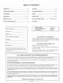
1
MANUAL
IVtodel No,
919,679370
Read the Safety
Guidelines
and All Instructions
Carefully
Before
• SAFETY
GUUDELUNES
ASSEMBLY
OPERATUON
MAUNTENANOE
o TROUBLESNOOTUNG
REPAUR PARTS
Operating
SoBd by Sears
MGP°679370A
8/f2/99
Canada,
inc°,
Toroato,
Oat,
MSB288
TABLE
Warranty
Safety
Assembly
...................................
3-8
...................................................
8
Operation
.............................................
9-13
......................................
13-15
Maintenance
Service
2
....................................................
Guidelines
OF CONTENTS
Adjustments
..............................
Storage
...................................................
Troubleshooting
.....................................
16
Parts ..................................................
17-31
EPA Codes
32-33
........................................
How To Order
15
15
Parts .................
Back Cover
Frangais
HORSE POWER
GASOLINE CAPACITY
OiL CAPACITY
DATE PURCHASED:
1
7.5 HP
4 GALLON
30 OZ.
MODEL NO:
SERIAL NO:
STORE WHERE PURCHASED:
MAmNTENANCE
AGREEMENT
The Craftsman Warranty, plus a Maintenance Agreement,
provide maximum value for your Sears products. Contact
your nearest Sears store for details.
ADDRESS
CiTY
CUSTOMER
TELEPHONE:
RESPONSIBILITIES
Read and observe the safety rules.
Follow a regular schedule in maintaining, caring for and us_
ing your generator.
Record the above information about your unit
so that you will be able to provide it in case
of boss or theft.
Follow the instructions under "Customer Responsibilities"
and "Storage" sections of this owner's manual.
FULL ONE YEAR WARRANTY ON CRAFTSMAN
GENERATORS
For one year from the date of purchase, when this Craftsman generator is maintained and operated according
instructions in this owner's manual, Sears will repair, free of charge, any defect in material and workmanship.
mfyour Craftsman Generator
original date of purchase.
is used for commercial
FULL ONE YEAR WARRANTY
or rental purposes,
ON CRAFTSMAN
this warranty
to the
applies for only 90 days from the
ENGINE
For one year from the date of purchase, when this Craftsman engine is maintained and operated according
instructions in this owner's manual, Sears will repair, free of charge, any defect in material and workmanship.
to the
mfyour Craftsman engine is used for commercial or rental purposes, this warranty applies only for 90 days from the date
of purchase. This warranty does not cover: Expendable items such as spark plugs and air filters, which become worn
during normal use.
Repairs necessary because of operator abuse or negligence, including damage resulting from no oil being supplied to
the engine or failure to maintain the equipment according to the instructions contained in this owner's manual, are not
covered under warranty.
WARRANTY SERVmCE mSAVAILABLE BY RETURMNG THE GENERATOR TO THE NEAREST SEARS SERVICE CENTER.
This warranty gives you specific legal rights and you may also have other rights, which vary from PROWNCE TO
PROWNCE.
Sold
by Sears
Oanada_
2 -- ENG
|ne,_ Toronto_
Ont,
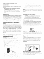
SAFETY
This manual contains information that
is important
for you to know and
understand. This information relates
to protecting YOUR SAFETY
and
PREVENTING EQUIPMENT PROBLEMS. "To help you recognize this
information, we use the symbols to
the right. Please read the manual and
pay attention
to these sections.
GUiDELiNES
- DEFiNiTiONS
I_, DANGER
]
URGENTSAFETYiNFORMATiON= A HAZ=
ARD THAT WiLL CAUSESERIOUSiNJURY
OR LOSSOF LIFE.
j ,_CAUTION
]
informationfor preventing damage 1;o
equipmen1:.
l _,WARN|NG
]
iMPORTANT SAFETY iNFORI_ATiON = A
HAZARD THAT MIGHT CAUSE SERIOUS
iNJURYOR LOSSOF LIFE=
l
NOTE
]
Informal:ion_a1: you s_ould pay
special atten1:ion1:o.
iMPORTANT
SAFETY
iNSTRUCTiONS
* SAVE THr=Sr= iNSTRUCTiONS
*
When using this product basic precautions should always be followed
including the following:
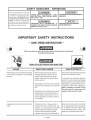
F_RSKOF ELECTF_OCUTRON
HAZARD
Attempting to connect generator directly
to the electrical system of any building
structure.
AND FRF_E
WHAT COULD HAPPEN
Back feeding electricity through a
building's electrical system to the
outside utility feed lines could en=
danger repair persons attempting to
restore service.
Attempting to connect to the incoming
utility service could result in electrocution.
Restoration of electrical service while
the generator is connected to the incoming utility could result in a fire or
serious damage if a isolator switch is
not installed.
Inadequate electrical grounding of generator.
The failure of one of the generator's
electrical devices, a broken wire, wet
surfaces, etc. could result in the entire
unit becoming electrically charged.
Contact with electrically charged
surfaces could result in electrocution.
3 -- ENG
HOW TO PREVENT UT
Never back feed electricity through a
structure's electrical system.
To connect to a structure's electrical
system in a safe manner and always
have a Double-Throw Transfer Switch
installed by a qualified electrician, in
compliance with local ordinances.
(When installing a Double-Throw
Transfer Switch, a minimum of 10
gauge wiring must be used.}
Make sure that the unit is connected
to an appropriate electrical ground,
_n accordance with the requirement
of the National Electric Code. See
page 8 for grounding instructions.
READ
AND UNDERSTAND
ALL WARNINGS
BEFORE
ATTEMPTING
TO OPEP_TE
CENEP_TOR.
RBSK OF ELECTROCUTBON
HAZARD
AND
FBRE ={cont'd}
WHAT COULD HAPPEN
HOW TO PRI:VENT iT
Water is an excellent conductor of
electricity! Water which comes in
contact with electricity charged
components can transmit electricity to
the frame and other surfaces, resulting
in electrical shock to anyone contacting them.
Operate generator in a clean, dry,
well ventilated area. Make sure
Contact with worn or damaged extension cords could result in electrocution.
Inspect extension cords before use
and replace with new if required.
Use of undersize extension cords could
result in overheating of the wires or attached items, resulting in fire.
Use proper size (wire gauge) cordset
for application.
Use of ungrounded cordsets could prevent operation of circuit breakers and
result in electrical shock.
Always use electrically
cordset.
Placing generator on or against highly
conductive surface, such as a steel
walkway or metal roof.
Accidental leakage of electrical current
could charge conductive surfaces in
contact with the generator.
Place generator on low conductivity
surface such as a concrete slab.
Improper connection of items to generator.
Exceeding the load capacity of the generator by attaching too many items, or
items with very high load ratings to it
could result in overheating of some
items or their attachment wiring resulting in fire or electrical shock.
Read the load rating chart and instructions on page 9, 10 and 11.
Make sure that the summation of
electrical loads for all attachments
Attempting to use the unit when it has
been damaged, or when it is not functioning normally could result in fire or
electrocution.
Do not operate generator with mechanical or electrical problem. Have
unit repaired by an Authorized Service Center.
Removal of guarding could expose elec=
trically charged components and result
in electrocution.
Do not operate generator with protective guarding removed.
Operation of generator in rain, wet, icy,
or flooded conditions.
Use of worn damaged, undersized or ungrounded extension cords.
Operation of unit when damaged, or with
guards or panels removed.
4 i
ENG
hands are dry before touching unit.
grounded
does not exceed the load rating of
the generator.
READ
AN{) UNDERSTAND
ALL VARNmNGS BEFORE
ATTEMPTBNG TO OPERATE GENERATOR°
RiSK
HAZARD
OF FiRE
WHAT COULD HAPPEN
HOW TO PREVENTUT
Attempting to fill the fuel tank while the
engine is running.
Gasoline and gasoline vapors can
become ignited by coming in contact
with hot components such as the
muffler, engine exhaust gases, or from
an electrical spark.
Turn engine off and allow it to cool
before adding fuel to the tank. Equip
area of operation with a fire extinguisher certified to handle gasoline
or fuel fires.
Sparks, fire, hot objects
Cigarettes, sparks, fires, or other hot
objects can cause gasoline or gasoline
vapors to ignite.
Add fuel to tank in well ventilated
area. Make sure there are no sources
of ignition near the generator.
Improper storage of fuel
Improperly stored fuel could lead to accidental ignition. Fuel improperly secured
could get into the hands of children or
other unqualified persons.
Inadequate ventilation for generator
Materials placed against or near the generator or operating the generator in areas where the temperature exceeds 104 °
R ambient can interfere with its proper
ventilation features causing overheating
and possible ignition of the materials.
Store fuel in a container designed to
hold gasoline. Store container in secure location to prevent use by others.
g_ln
a_
well ventilated area a minimum of four
feet from any objects or wall. DO
NOT OPERATE UNtT INDOORS OR
IN ANY CONFINED AREA.
Tampering with factory set engine speed
settings.
Engine speed has been factory set to
provide safe operation. Tampering with
the engine speed adjustment could resuet in overheating of attachments and
could cause a fire.
Never attempt to "speedup" the engine to obtain more performance.
Both the output voltage and frequency will be thrown out of standard by this practice, endangering
attachments and the user.
Overfilling the fuel tank - fuel spillage.
Spilled fuel and its vapors can become
ignited from hot surfaces or sparks.
Use care in filling the tank to avoid
spilling fuel. Make sure fuel cap is
secured tightly and check engine
for fuel leaks before starting
engine. Move generator away from
refueling area or any spillage before
starting engine. Allow for fuel
expansion. Keep maximum fuel
level % inch below the tip of the
fuel tank. Never refuel with the
engine running.
5 -- ENG
READ AN{) UNDERSTAND
ALL VARNmNG$
BEFORE
ATTEMPTBNG TO OPERATE GENERATOR.
Risk of injury and Property
Damage
Trans_
Generator
HAZARD
WHAT COULD HAPPEN
Fire, hhalafion, Damage to Vehicle
Surfaces
Fuel or oil can leak or spill and could
result in fire or breathing hazard, serious injury or death can resulL Fuel or oil
leaks will damage carpet, paint or other
surfaces in vehicles or traibrs.
When
HOW TD PREVENT iT
If generator is equipped
with a fuel
shut-off valve, turn the valve to the
off position
before transporting
to
avoid fuel leaks, If generator
is not
equipped
with a fuel shut-off valve,
drain the fuel from tank before transporting. Only transport fuel in an CSA
approved
container, Always place
generator on a protective mat when
transporting
to protect against damage to vehicle from leaks, Remove
generator from vehicle immediately
upon arrival at your destination
RiSK OF BREATHING
HATARD
Gasoline engines produce toxic carbon
monoxide exhaust fumes.
- INHALATION
WHAT COULD HAPPI:N
Breathing exhaust fumes will cause serious injury or death.
HAZARD
HOW TO PRr:VENT IT
Operate generator in clean, dry, well
ventilated area. Avoid enclosed areas like garages, basements, storage sheds, etc, which lack a steady
exchange of air. Never operate unit
in a location occupied by humans or
animals. Keep children, pets and others away from area of operating unit.
6 -- ENG
READ AN{) UNDERSTAND
ALL WARNmNGS BEFORE
ATTEMPTBNG TO OPERATE GENERATOR°
RiSK
of generator
OPERATION
WHAT COULD HAPPEN
HAZARD
Operation
manner.
OF UNSAFE
in careless
Operation of voltage sensitive appli=
ances without a voltage surge protector.
HOW
TO PREVENTUT
All sources of energy include the potential for injury. Unsafe operation or maintenance of your generator could lead to
serious injury or death to you or others.
o Review and understand all of the
Any gasoline operated household generator will incur voltage variations causing damage to voltage sensitive appliances or result in fire.
Always use U.L listed voltage protector to connect voltage sensitive
appliances (TV, computer, stereo,
etc.). Failure to use a U.L listed volt=
age surge protector will void the warranty on your generator.
operating instructions and warnings in this manual.
o Become familiarwith the operation
and controls of the generator.
Know how to shut it off quickly.
o Equip area of operation with a fire
extinguisher certified to handle
gasoline or fuel fires.
o Keep children or others away from
the generator at all times.
Notice: A multiple outlet strip is not
a surge protector make sure you use
a U.L. listed voltage surge protector.
RiSK OF HOT
HAZARD
Contact with hot engine and generator
components.
WHAT
Contact with moving parts can result in
serious injury.
HAPPEN
HOW
Contact with hot surfaces, such as em
gines exhaust components, could result
in serious burns.
RiSK
HAZARD
COULD
SURFACm=S
OF MOVING
WHAT COULD
TO PREVENT
UT
During operation, touch only the control surfaces of the generator. Keep
children away from the generator at
all times. They may not be able to
recognize the hazards of this product.
PARTS
HAPPEN
The generator contains parts which rotate at high speed during operation.
These parts are covered by guarding to
prevent injury.
HOW
TO PREVENTiT
Never operate generator with guarding or cover plates removed. Avoid
wearing loose fitting clothing or jewelry which could be caught by moving parts.
READ
AND UNDERSTAND
ALL WARNINGS
BEFORE
ATTEMPTBNG TO OPERATE GENERATOR°
RiSK
HAZARD
FROM
LiFTiNG
WHAT COULD HAPPEN
Lifting a very heavy object.
HOW TO PREVENT iT
Serious injury can result from attempting to lift too heavy an object.
The generator is too heavy to be lifted
by one person. Obtain assistance
from others before you try to move
it.
Read Owner's Manual Do not operate equipment unflH you have read Owner's ManuaH for
Safety, _
and Maintenance Instructions,
This product is not equipped with a spark arresting muffHer. If the product will be used around flammable materials, or on
land covered with materials such as agricultural crops, forest, brush, grass, or other similar items, then an approved spark
attester must be installed and is legally required in the state of California. it is a violation of California statutes section
130050 and/or sections 4442 and 4443 of the California Public Resources Code, unless the engine is equipped with a spark
arrestor, as defined in section 4442, and maintained in effective working order. Spark arrestors are also required on some
U.S. Forest Service land and may also be legally required under other statutes and ordinances.
Engine exhaust contains chemicals known, in certain quantities, to cause cancer, birth defects or other reproductive harm.
CARTON
CONTENTS
Main Unit
Owner's Manual
Battery
Battery Charge Cables
OwnerBs
Main
Generator
REMOVE
GENERATOR
FROM
CARTON
Open carton from top.
Cut carton along dotted lines.
Cables
Unit
GROUNDBNG
CAUTION: Read owner's manual. Do not attemptto
operate equipment until you have read Owner's
Manual for Safety, Operation, and Maintenance Instructions.
Charge
ManuaJ
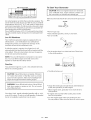
THE GENERATOR
This generator should be grounded to help prevent
accidental electrical shock. Shown below is a picture of
the grounding lug supplied on your generator. First, drive
a 3/4" or 1" diameter copper pipe or rod into the ground
close to the generator set. The pipe must penetrate moist
earth. Using #10 gauge wire, connect one end of the wire
into the grounding lug. Next, connect the other end of the
wire to the copper pipe or rod using an approved ground
clamp.
Remove all carton inserts.
I}
Remove generator through opening in carton.
iMPORTANT: Before any attempt to start your generator
be sure to check engine oil (See OPERATION under
Engine Oil on page 11)
Grounding
8 -- ENG
Lug
KNOW YOUR
120/240 VOLT TWISTLOCK RECEPTACLE- Used to
supply 1800 watts of electrical power for 120 volt operations
and for 240 volt operation 3750. Wiil only supply 1875 watts
each if both receptacles are being used. Protected by 15
amp circuit breaker.
GENERATOR
Read this Owner's IVianual and Safety Rules be_
fore operation of your Generator, Compare this
illustration with your generator to familiarize yourself
with the location of various controls and adjustments.
Save the manual for future references.
120 VOLT TWISTLOCK RECEPTACLE- Used to supply
1800 watts of power per receptacle protected by a 15 amp
circuit breaker_
FUEL TANK= Capacity of 4 US gallons.
CHOKE SWITCH= Lever used to start cold engine.
AIF( CLFJ_HER-(nciudes filter element and foam pre-cieaner
that limits the amount of dirt that enters the engine.
ENGINE RUN/STOP SWITCH= Sets engine in starting
mode for recoil starter - Stops running engine.
ENGINE OiL FILL- Place where engine oil is poured.
CiRCUiT BREAKER= Each receptacle has a circuit
breaker to protect the generator from overloading.
120 VOLT DUPLEX RECEPTACLES- Used to supply 1800
watts of electrical power per receptacle for operations.
Protected by 15 amp circuit breaker.
FULL POWER SWITCH - Switch used to convert every
receptacle on the panel, when placed in the 120 position,
to a 120 volt receptacle. This wiil allow you to receive the
fuil capacity of the generator by using ail 120 volt receptacles. When in the 120/240 position, you wiil only be able
to use half of the 3750 watts when using the 120 volt receptacles. But in this position, the fuil 3750 watts can be received in the 240 twistiock receptacle.
IDLE COHTROL SWITCH- When on, allows the engine to
run at a lower speed when there is no load on the generator.
AiR CLEANI=R
(DLE CONTROL
SW(TCH
FULL
POWER
SWITCH
t 20/240
TWJSTLOCK
RECEPTACLE
t 20 TW|STLOCK
RECEPTACLE
9 -- ENG
GENERATOR
Your generator is equipped with dupbx 120 voit receptacb
a 120 twbfiock and a 120/240 voit twisfiock receptacb.
The unit is ariseequipped with a 15 amp circuit breaker for
the dupbx 120 voit receptacbs, a 15 amp circuit breaker
for the 120 voit twistiock receptacb and a 15 amp circuit
breaker for the 120/240 voit twisdock receptacb. If the circuit breaker trips, unpiug aHebctrbai Headsfrom the generator. Let the circuit breaker cooi down. Push circuit breaker
button to reset.
@
120V
@
120/240V
OFF
12V1OA DO
CAPACWY
Exceeding the rated capacity of your generator carl
result in serious damage to your generator and connected
electrical devices. You should observe the following to
prevent overloading the unit:
Starting and running wattage requirements must be
calculated to match your generator wattage capacity.
Resistive load appliances
such as light bulbs, TV's
and microwaves,
have the same starting and running
wattage. The wattage used for calculating
the capacity
can usually be found on each of these appliances.
Some inductive appliances
and tools wiii iist on the motor
name plate, the starting and running voltage and amperage
requirements.
Use the following formula to convert voltage
and amperage to wattage:
ON
_Volts X Amp = Watts}
120/30A
120V 15A
(Combined total
from both outlets)
FULL
POWER
Inductive load appliances and tools such as refrigerators,
air compressors and washers require approximately 2 to
4 times the listed running wattage for starting the equipment. This initial load only lasts for a few seconds on
start-up but is very important when figuring your total
wattage to be used.
240V 20A
or
120V 20A / 120V 20A
SWmTCH
Your Craftsman generator has a full power switch on the
controi panel This switch has two positions: 120 VOLT
ONLY, and 120/240 VOLT.
120 Position
NOTE: Always start your largest electric motor first, and
then plug in other items, one at a time.
The guide below is provided to assist you in determining
the appliances
and tools that can be ran with the wattage
capacity of your generator.
When placed in the 120 position, (Shown below) every receptacb on the panel will be converted to a 120 volt receptacb. 240-volt power is not available. This position allows
full capacity of the generator to be received by using all
120-volt receptacles. While in the 120 position, each receptacb has the ability to reach the maximum 4650 surge
wattage for inductive motors that require 4650 watts or below to start.
120V
120/240V
1201240 Position
When in the 120/240 position, (Shown Below) only half of
the 3750 watts carl be received when using the 120-volt
receptacles and the 120/240-volt twistlock receptacle will
be converted to allow the full 3750 watts to be received
from this one receptacle. Also in this position, the 120-volt
receptacles will only reach a maximum of 4650 surge watts.
120V
120/240V
10 -- ENG
OBTAmNING ELECTRBC_TY
FROM
Start the engine. Let it run while the battery charges.
When the battery is fully charged, stop the engine
and disconnect the battery charge canes from the
panel and battery. Batteries should not be charged
when the unit is unattended.
There are basicaiiy two ways to obtain eiectrbity form a
generator:
Use of extension cords directly form the generator
to the appiiance, iights, toois, etc.
NOTE- _ llb not
Use of a doubie-throw transfer switch instaiied
directly to the main eHectrbaHsuppiy outside of the
house.
Extension
not
BEFORE
When using an appliance or tool at a considerable distance
from the generator, a 3-wire extension cord that has a 3blade grounding plug and 3-dot receptacle that accepts
the tool's plug should be used. A cord of adequate size
must be used. A minimum of 12 gauge wire size with at
least a 20 amp draw can be used. When amperage
exceeds 20 amps a 10 gauge wire size should be used.
Generator
To Main
Eleetrieam
SuppJy
Potenfiai hazards exist when a eiectricai generator is connected to the main eiectricai suppiy coming into the house.
It is at that point that the generator couid feed back into the
utiiity company's system causing possibie eiectrocution of
workers who are repairing electrical lines. To avoid back
feeding of electricity into utility systems, a double-threw
transfer switch should be installed between the generator and utility power. This device should be installed by a
licensed electrician and in compliance with all local electrical codes.
NOTE: When installing a Double-ThrowTransfer
a minimum of 10 gauge wiring must be used.
CHARGBNG
the
Switch,
A BATTERY
iMPORTANT: Always use safety glasses, rubber gloves
and protective clothing while charging battery.
Your generator has the capability of recharging a 12-volt
storage or automotive battery. To recharge a 12-volt
battery, proceed as follows:
use the
unit
to
-_t
crank
to c_
any 6_olt
an engine
having
_atteries°Ds
a discharged
b_ttey°
Cord
Connecting
use
STARTRNG
ENGINE
CAUTION: Always check engine oil level before
every start. Running engine low of oil or out of oil
could result in serious damage to the engine
Automatic
BdUeControU
The automatic idle control switch, when in the ON position, allows the engine to run at lower speed when there
is no load on the generator. This wiii lower the engine
noise, save on fuel consumption and engine life. When in
the OFF position the engine wiii run at 3600 RPM's
continuous with or without a load.
ON
OFF
m:_L
D EC }ON1TRQLL
NOT_=: The idie contrbTmust b-e untSe OFF position when
operating iarge motor ioads (Refrigerators, freezers, etc.) or
voitage sensitive eiectronic equipment (TV,computers, etc.)
Engine
OiU
Your unit has been shipped without oii in the engine. A
bottle of SAE 30 weight oii is inciuded in the carton.
Remove oii dip stick iocated on the side of engine. The
oii dip stick is cieariy marked with a iine that teiHsyou
when unit has enough oil Do not firthabove this point
Pour slowly.
First, check the fluid level in all of the battery cells.
Add distilled water if necessary. Do not use tap
water,
CLEAN
Clean battery posts if necessary.
Connect battery charge canes to panel receptacle
Connect the battery charge cane with the red handle
to the battery post indicated by POS or (+).
Connect the battery charge cane with the black
handle to the battery post indicated by NEG or (-).
me crankcase
1the
futur
Service SF, SG, SH" rated SAE 30 weight. Use no special
additives.
Select the oil's viscosity grade according
to
you expected operating temperatures.
11 -- ENG
To Start
$AE Viscesi_y Grades
Your Generater
poor ventilated areas, engine exhaust contains carCAUTION: Never run engine indoors or in enclosed,
bon monoxide, an ordoriess and deadly gas.
Air cooled engines run hotter than automotive engines. The
use of multi-viscosity oil such as (10W-30, etc.) in ambient
temperatures above 40°F (4°C) wiii result in higher than
normal oil consumption. If multi-viscosity oil is used, check
the oil level more frequently to prevent any posssible engine damage due to lack or lubrication.
Use of SAES0 oii below 40°F (4°C) wiii result in hard starting and possible engine damage due to inadequate lubrication.
Make sure the fuel shutoff valve is turned to the open position.
CLOSE
o Remove gas cap
Add unleaded gasoline, slowly, to fuel tank.
Do not overfiii.
Lew Oil Shutdown
Your Craftsman generator engine is equipped with Low
Oil Shutdown. Low Oil Shutdown is a safetydevice
designed to protect your engine from damage in the
event the oil level in the crankcase is low.
If while the engine is running, the oil gets low, it wiii
automatically shut itself down and wiii not restart until the
oil is added. If the oil is low before start-up, the generator wiii not start until oil is added.
On the engine there is a choke/run lever. Place lever
NOTE: The Low Oil Shutdown mechanism is very sensitive. You must fill the engine to the full mark on the
dipstick to inactivate this safety device.
Gasoline
CHOKE
Your generator engine is 4 cycle. Use unleaded fuel only.
Never mix oil with gasoline.
Throttle is factory seL
CAUTION: Never fiii fuel tank completely. Fiii tank to
1/2" below the bottom of the filler neck to provide
space for fuel expansion. Wipe any fuel spillage from
engine and equipment before starting engine.
ON
WARNING:
Neverfill fuel tank indoors. Never fill fuel
Grasp the starter grip and pull slowly until resistance
is felt, then pull firmly to start engine.
tank when engine is running or hoL Do not smoke
when filling fuel tank.
o When engine starts, gradually move choke lever to
RUN position.
Use clean, fresh, regular unleaded gasoline with a minimum of 85 octane. Do not mix oil with gasoline. If unleaded
fuel is not available, leaded fuel may be used.
12 -- ENG
If engine does not start after 5 pulls, place choke
back to run position.
For hot engine starts make sure choke lever is in
the run position. Make sure fuel shut off valve is open.
1
Cennectin9
Electrical
Loads
Steppin9
Let engine run and warm up for about five minutes
The Engine
Disconnect all electrical loads.
Switch the start/off switch to the off position.
Piug in the desired 120 or 240 voits toob.
DO NOT connect 240 volt equipment to the 120 volt
duplex receptacles.
DO NOT connect 3-phase loads to the panel
receptacles.
iMPORTANT;
You should always add up the rated
watts of all lights, tools and appliances you are powering at one time. This total should not exceed the rated
capacity of your generator or circuit breaker rating of
the receptacle supplying power.
CUSTOMER
RESPONSBBBLBTBES
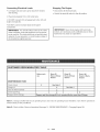
TABLE
Before each
use
MAINTNENANCE
iMPORTANT:
Never store engine with fuel in tank,
indoors, or in enclosed, poorly ventilated areas or where
fuel fumes may reach an open flame.
Every 25
Hours of Every
Season
Every 50
Hours of Every
Season
Every i00
Hours of Every
Season
TASK
Check oil leve!
X
See Note 2
Change oil
X
Clean Air Filter Assembly
X
Check Spark Plug
X
Prepare Unit for Storage
See Note 1
x
Prepare unit for storage if it is to remain idmefor more than 30 days,
Note 1: Change oil after first two (2) operating hours and every 50 operating hours thereafter, more often if operated in
extreme dusty or dirty conditions.
Note 2: Check oil after 5 hours of operation (See page 14 - ENGINE MAINTENANCE - Changing Engine Oil.)
13 -- ENG
GENERAL
RECOMMENDATBON$
Reinstall the oil fill cap or plug and tighten securely.
The warranty of the generator does not cover items that
have been subjected to operator abuse or negHigence. To
receive full vaHuefrom the warranty, operator must maintain
the generator as instructed in this manual
FULL_
Some adjustments will need to be made periodically to
maintaining your generator.
Service
GENERATOR
MAINTENANCE
Your generator shouHd be kept dean and dry at aHtimes.
The generator shouHd not be stored or operated in
enviroments that incHudes excessive moisture, dust or any
corrosive vapors. If these substances are on the generator,
dean with a cloth or soft bristHebrush. Do not use a garden
hose or anything with water pressure to cHeanthe generator. Water may enter the cooling air slots and could possibly damage the rotor, stator and the internal windings of the
gen head.
All adjustments in the Maintenance section of this manual
should be made at least once each season.
ENGINE
Engine
Oim
For a new engine, change oil after the first 5 hours of
operation. Thereafter, change oil after every 50 hours of
operation.
Change the oil while the engine is still warm. The oil will
flow freely and carry away more impurities. Make sure the
engine is level when filling, checking, or changing oil.
Change
NOTE: Do not use petroleum solvents, e.g., kerosene,
which will cause the cartridge to deteriorate. Do not use
pressurized air to clean cartridge. Pressurized air can
damage the cartridge.
To service
air cleaner
follow these
steps:
1. Unscrew cover screws.
Remove cover and air
cleaner assembly.
2. Remove cartridge from cover, then retainer
(if equipped) and pre-deaner.
To service pre-deaner, wash in liquid detergent and
water. Squeeze dry in a clean cloth. Saturate in engine
oil. Squeeze in clean, absorbent cloth to remove all
excess oil. Replace if very dirty or damaged.
To service cartridge, clean by tapping gently on a flat
surface. Do not oil cartridge. Replace if dirty or damaged.
MAINTENANCE
Changing
Air Cleaner
the oil as follows:
3. Reassemble pre-deaner or retainer (if equipped.)
Place in cover with pre-cleaner mesh side toward
cartridge. Place cartridge in retainer in cover.
4. Push cover and air cleaner assembly squarely onto
base (tabs must be in slots, if equipped) and hold
firmly. Tighten cover screws securely.
To keep dirt, grass clippings, etc., out of the engine,
clean the area around the drain plug and dipstick
before removing it.
Remove the oil drain plug and dipstick. Tilt the engine
slightly towards the oil drain to obtain better drainage.
Be sure to allow ample time for complete drainage.
Do not clean engine with a forceful spray of water
because water could contaminate fuel system. With
a brush or cloth clean finger guard after every use to
prevent engine damage caused by overheating.
Reinstall the drain plug. Make sure it is tightened
securely.
Fill the crankcase with new oil of the proper type, to
the Full mark on the dipstick. Always check the level
with the dipstick before adding more oil.
14 -- ENG
Before running engine, clean muffler area to remove all
combustible debris.
Clean and Replace Spark Plug
Change the spark plug every 100 hours of operation or
once each year, whichever comes firsL This will help
your engine to start easier and run better.
RESISTOR
Carburetor
The carburetor
of your generator is pre-set at the factory.
The carburetor
should not be tampered
with. if your generator is used at an altitude in excess of 4000 feet performance may be affected.
If so consult with your nearest
Sears Service Center regarding high altitude set changes.
GovePnoP
Your engine governor maintains the constant operating
speed of your generator. DO NOT tamper with the engine
governor which is factory set for proper engine speed.
If you are going to store your generator for more than 30
days, use the following information
as a guide to prepare
the generator
STORAGE
for storage.
BNSTRUCTBONS
CAUTION:
Never store generator with fuel in the
tank indoors or in enclosed, poorly ventilated areas,
where fumes can reach an open flame, spark or pilot
light as on a furnace, water heater clothes dryer or
other gas appliances.
Engine
Preparation
Add fuel stabilizer to fuel tank to minimize the
Over-speeding
your engine above factory high speed setting can be dangerous
and couUd possibly cause personal
injury or property damage. If you believe the engine is running too fast or slow, take your generator to a Authorized
Sears Service Center for repair and adjustment.
CAUTION: Low engine speeds impose a heavy load
on the engine and when sufficient power is not available the engine life could be shorten.
Disconnect the spark plug wire and remove the
spark plug.
Add one teaspoon of oii through the spark piug hob.
Place rag over spark plug hole and pull the recoil a
few times to lubricate the combustion chamber.
Replace the spark plug, but do not connect the spark
plug wire.
NOTE: If a fuel stabilizer is not used, all gasoline must
be drained from the tank and carburetor to prevent gum
deposits from forming on these parts and causing
possible malfunction of the engine.
formation of fuel gum deposits during storage.
Generator
Run engine at bast 10 minutes after adding stabilizer
to allow it to enter the fuel system.
Clean the generator as outlined on Page 14 (Generator
Maintenanc@
Next shut off engine.
Check that cooiing air dots and openings on generator
are open and unobstructed.
15 -- ENG
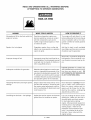
CORRECTION
Engine
will not start
1.
Low on fuel or oil.
1. Add fuel or oii.
2.
Ignition switch in "Off" position.
2. Turn to "ON" position
3.
Faulty spark plug.
3. Replace spark plug.
4.
Choke in wrong position.
4. Adjust chokeaccordingiy.
5.
Fuel shut-off valve in closed
5. Open fuel shut-off valve.
position.
6.
Unit loaded during start-up.
6,
Removeload
7.
Spark plug wireloose.
7,
Attach
1.
Faulty receptacle.
1,
Have Service
2.
Circuit breaker kicked out.
2,
Depress
3.
Defective capacitor.
3,
Have Service
capacitor,
4.
Faulty powercord.
4,
Repair or replace
5.
GFCI switch breaker kicked out (if
equipped)
5. Depress
Repeated circu# breaker tripping
1.
2.
Overload
Faulty cords or equipment.
,
Reduce load.
2. Check for damaged, bare, or
frayed wires on equipment.
Replace.
Generator overheating
1.
Generator overloaded.
1. Reduce load.
2.
Insufficient ventilation.
2. Move to adequate supply of
fresh air.
No electrical
No auto
output
idle
DC does not have power with the
circuit breaker depressed
from
unit,
wire to spark plug,
Center replace,
and reset,
Center replace
cord,
and reset
1. Faulty solenoid
1. Have Service
Center replace.
2. Faulty idle control switch
2. Have Service
Center replace.
3. Faulty windings in stator
3. Have Service
Center replace.
4. Faulty circuit board
4. Have Service
Center replace.
5. Faulty wire harness
5. Have Service
Center replace
1. Faulty rectifier
1. Have Service Center replace.
2. Faulty windings in stator
2. Have Service Center replace.
3. Faulty wire harness
3. Have Service Center replace.
16 -- ENG
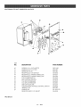
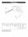
CRAFTSMAN
3750
WATT GENERATOR
919,679370
13
12
LJE 20-25
10
IN-LB:
11
5
7
8
6 TORQUE 120-144 IN-LBS
4
TORQUE
96-120
IN-LBS
2
TORQUE
60-70
IN-LBS
KEY
NO,
1
2
3
4
5
6
7
8
9
lO
11
12
13
DESCRiPTiON
PART NUMBER
HEAT SHELD
GS-816
91895680
GS-0227
SSF-605
SSN-60-ZN
SSF-8150
SSN-1619-ZN
SCREW, 1/4-20 x .75
FUELCLAMP
SCREW, 5/16-18 X 1.25
WASHER
NUT, HEX WIZ LOCK
WASHER, LOCK
GROUND STRAP
CAP SCREW, 5/16-18 X 3A
FUEL TANK (4 GALLON)
ENGHNE
WASHER, =875OD =35HD=083THK
FUEL TANK CAP
17 -- ENG
GS-0118
SS-12-SD
GS-0650
GS-0665
SSN-632
GS-0443
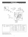
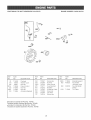
CRAFTSMAN
3750
WATT GENERATOR
919o679370
'\
\
\
L_%_ 14
TORQUE 20-25 mN-LBS
14
15
16
17
18
19
2O
21
22
23
24
FUEL HOSE
DRAHNCOCK GROMMET
FRAME ASSEMBLY
GENERATOR ASSEMBLY
GROUND LUG
SCREW, HEX WASHER,
VIBRATION ISOLATOR
VIBRATION ISOLATOR
UNSLOTTED
SCREW, 10-24 x 9/16
DRAIN COCK
END COVER
18 -- ENG
GS-0225
GS-0446
G8-0611
GS-0672
GS-0117
SSF-928
GS-0033
GS-0433
SSF-553-1
GS-0437
GS-0077
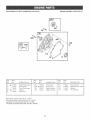
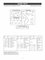
CRAFTSMAN
3750
WATT GENERATOR
919,679370
26
27
3O
28
34
\
35
36
37
38
SHOWN
FOR REFERENCE
ONLY
29
32
33
25
24
SHOWN
FOR REFERENCE
KEY
NO,
DESCRiPTiON
PART NUMBER
24
25
26
27
28
29
30
31
32
33
34
35
36
37
38
39
RECTiFiER
SCREW, 10-24 X .75 T25 TORX
DRIVE END ADAPTER
LOCK WASHER 3/8
CAP SCREW, 3/8-16 X 1
ROTOR ASSEM BLY
STATOR THRU BOLT
STATOR ASSEMBLY
W/ASHER 11/16 OD X 11/32
NUT, 5/16-24
ROTOR THRU BOLT
BEARING SUPPORT
HEX NUT %-20
CAPACITOR
CAPACITOR BRACKET
SCREW 10-32
GS-0767
SSF-3158-1
GS-0830
SSN-619
SSF-577
GS-0588
GS-0110
GS-0673
SS-6506-CD
SSF-576
GS-0091-1
GS-0793
SSF-575
GS-0748
GS-0595
SSF-553-1
ITEMS NOT SHOWN
GS-0082
*Diode(s) --
19 -- ENG
ONLY
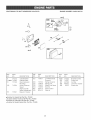
CRAFTSMAN
3750
WATT GENERATOR
919,679370
KEY
NO,
DESCRiPTiON
PART NUMBER
4O
41
42
43
44
45
46
47
48
49
5O
51
52
53
SCREW, 10-9 x .50 PLASTITE
SCREW, #6-32 X .5 TORX
SPEED NUT #6-32
SSF-3156
SSF-583
SSF-584
GS-0804
GS-0021
GS-0445
GS-0045
GS-0679
GS-0024
GS-0681
GS-0207
GS-0663
SSF-595
SS-1525-CD
GS-0835
RECEPTACLE, 120V DUPLEX
RECEPTACLE, 3 PRONG TWISTLOCK
RECEPTACLE, 4 PRONG TWISTLOCK
FULL POWER SWITCH
IDLE CONTROL SWITCH
15A CiRCUiT BREAKER
10A CIRCUIT BREAKER
SWITCH FACE PLATE
CiRCUiT BOARD FOR BDLECONTROL SWITCH
JAM NUT 7,116
WASH ER3/8
RESISTOR ASS_I D.C. SHUNT
*Not Shown
20 -- ENG
CRAFTSMAN
3750WATTGENERATOR
919,679370
ENGINE
NUMBER
138432=0035=A1
17
3
©
REF.
NO.
t
3
PART
NO.
7t 5461
¢710000
ohcluded
_hciuded
Mncluded
÷hcluded
DESCRIPTION
Cylinder Assembly
Seal-Oil
REF.
NO.
PART
NO.
10
15
17
1t6
116A
227
230
277
306
356
710023
715000
710003
¢710055
¢710091
710051
¢710058
710004
710063
710308
in Gasket Set-Part No. 715482
inValve Overhaul Kit-Part No. 715483
in Carburetor Kit-Part No= 715484
in Gasket Gasket Set -Part No= 715485
21
DESCRIPTION
REF.
NO.
PART
NO.
DESCRIPTION
Screw-Hex
Plug-Oil Drain
Bearing-Ball
Seal-O-Ring
Seal-O-Ring
Lever-Governor
Washer-Spacer
Washer-Seal
Sheild-Cylinder
Wire-Oil Sensor
373
505
6t4
616
718
725
89O
1019
1052
1058
710059
710090
710056
710636
710005
710102
715136
715031
715353
273126
Nut-Lock
Nut-Lock
Pin-Retainer
Crank-Governor
Pin-Locating
Sheild-Heat
Bracket-Su pport
Label Kit
Sensor-Oil
Owner's Manual
CRAFTSMAN
3750WATTGENERATOR
919o679370
ENGINE
NUMBER
138432=0035=A1
718
REF.
NO.
12
17
t8
20
22
PART
NO.
¢ 710628
710003
715463
€ 710215
710032
DESCRIPTION
Gasket-Crankcase
Bearing-Ball
Cover-Crankcase
Seal-Oil
Screw-Hex.
REF.
NO.
PART
NO.
DESCRIPTION
REF.
NO.
PART
NO.
DESCRIPTION
22A
1t6B
219
220
710306
o710029
715341
710035
Screw-Hex
Seal-O-Ring
Gear-Governor
VVasher-Spacer
221
225
523
718
710027
710028
715007
710005
Cup-Governor
Shaft-Governor
Dipstick
Pin-Locating
ohcluded in Gasket Set-Part No. 715482
_hcluded inValve Overhaul Kit-Part No. 715483
Mncluded in Carburetor Kit-Part No. 715484
÷mncHuded in Gasket Gasket Set -Part No. 715485
22
Gear
CRAFTSMAN
3750WATTGENERATOR
919,679370
ENGINE
NUMBER
138432=0035=A1
4_0A
_4°
40 868
53
10
1026
383
REF.
NO.
PART
NO.
5
715444
7 ¢*710624
10
710023
t3
710020
33
715445
34
715446
35
710011
40
710012
40A
715130
olncluded
_lncIuded
_mncluded
÷mncluded
REF.
NO.
DESCRIPTION
Head-Cylinder
Gasket-Cylinder
Screw-Hex
Screw-Hex
Valve-Exhaust
Valve-Intake
Spring-Valve
Retainer-Valve
Retainer-Valve
Head
PART
NO.
45
53
710008
710148
53A
710099
337
373A
383
491055
710007
19374
551
715450
DESCRIPTION
Tappet-Valve
Stud-Carburetor
Mounting
Stud
(Muffler Mounting)
Plug-Spark
Nut-Lock
Wrench-Spark
Plug
Cover-Rocker
in Gasket Set-Part No. 715482
inValve Overhaul Kit-Part No= 715483
in Carburetor Kit-Part No. 715484
in Gasket Gasket Set -Part No. 715485
23
REF.
NO.
PART
NO.
635
710634
830
710016
868
o7t0019
1022 ¢_10626
1026
1029
t034
1050
710622
710014
710017
710015
DESCRIPTION
Boot-Spark Plug
Stud-Rocker Arm
Seal-Valve
Gasket-Rocker
Cover
Rod-Push
Arm-Rocker
Guide-Push Rod
Adjuster-Rocker Arm
CRAFTSMAN
3750WATTGENERATOR
919o679370
ENGINE
NUMBER
138432=0035=A1
32
REF.
NO.
PART
NO.
16
715426
DESCRIPTION
Crankshaft
Used on Type No(s).
0035, 0084
REF.
NO.
PART
NO.
25
715456
715457
DESCRIPTION
REF.
NO.
PART
NO.
Piston Assy.
(Standard)
Piston Assy.
27
28
29
710040
715455
715427
(.010" O.S.)
715448
26
Piston Assy.
(.O20" O.S.)
Ring Set
(Standard)
Ring Set
(.010" O.S.)
Ring Set
(.010" O.S.)
715452
715453
715454
®Included
_lncluded
Mncluded
÷mncluded
in Gasket Set-Part No. 715482
inValve Overhaul Kit-Part No. 715483
in Carburetor Kit-Part No. 715484
in Gasket Gasket Set -Part No. 715485
24
715502
32
710041
46
7 t 8A
1051
715451
710616
710039
DESCRIPTION
Lock-Piston Pin
Pin-Piston Std.
Rod-Connecting
(Standard)
Rod-Connecting
(.020" Undersize)
Screw-Connecting
Rod
Grear-Cam
Pin-Compression
Ring-Retaining
CRAFTSMAN
3750WATTGENERATOR
919,679370
ENGINE
NUMBER
138432=0035=A1
105_
REF PART
REF PART
NO
NO
DESCRIPTION NO NO
51O*A4,710060Gasket-Intake 130 710671
95
710672 Screw-Round
Head 13t 715480
98
715478 Screw-idle
Speed 133 715477
104 ¢ 710663 Pin-Float
137 ¢÷
105 € 710661 Valve-Needle
t 08 710674 Valve-Choke
138 ¢÷
117 ¢ 710665 Jet-Main
-NOTEJet-Main
(High Altitude)
715034
Spacer-Carburetor
715473
Carburetor
710719
122
125
ohcluded
_hcluded
_hcluded
÷hcluded
REF PART
DESCRIPTION NO NO
Valve-Throttle
634A O
Shaft-Throttle
Float-Carburetor 634B
Gasket-Float
Bowl
(SoldinKitOnly)
Washer
955
710667
(SoldinKitOnly)
141
142
147
715479
Choke Shaft Kit
€ 710664
Nozzle-Carburetor
€ 710675
Jet-Pilot
-NOTE710720
Jet-Pilot
(High Altitude)
154
710081
Nut-Hex
163O_A÷710639
Gasket-Air Cleaner
620
710635
Bracket-Control
in Gasket Set-Part No. 715482
inValve Overhau_ Kit-Part No. 715483
in Carburetor Kit-Part No. 715484
in Gasket Gasket Set -Part No. 715485
25
955A
975
710679
715476
DESCRIPTION
Seal-Throttle Shaft
(Sold in Kit Only)
Bushing-Choke
Shaft
(Sold in Kit Only)
Screw-Bowl
Mounting
Plug-Carburetor
Bowl-Float
CRAFTSMAN
3750WATTGENERATOR
919,679370
ENGINE
NUMBER
138432=0035=A1
0
46?
2o2/_i_32_
REF.
NO.
PART
NO.
1t
710115
51 ¢,A4,710060
53
710148
129
715024
161
710521
ohcluded
_hcHuded
Ahcluded
÷hcHuded
DESCRIPTION
NO.
PART
NO.
Tube-Breather
Gasket-Intake
Stud-Carburetor
Mounting
Screw-Governor
Speed
(High and Idle
Speed Adjustment)
Base-Air Cleaner
202
710637
209
232
235
354
467
535
710702
710638
710522
710068
280715
491435
REF.
DESCRIPTION
Link-Mechanical
Governor
Spring-Governor
Spring-Link
Shield-Fuel Spray
Nut-Hex
Knob-Control
Filter-Air
in Gasket Set-Part No. 715482
inVaHve Overhau_ Kit-Part No. 715483
in Carburetor Kit-Part No. 715484
in Gasket Gasket Set -Part No. 715485
26
REF.
NO.
PART
NO.
DESCRIPTION
620B
663
967
968
969
715025
710057
491588
495872
93473
Bracket-Control
Screw-Hex
Air Filter
Cover-Air Cleaner
Screw-Hex
CRAFTSMAN
3750WATTGENERATOR
919,679370
ENGINE
NUMBER
138432=0035=A1
823
883f
585
673
573 _
REF.
NO.
PART
NO.
53A
710099
300
408
505
ohcluded
_hcHuded
Ahcluded
÷hcHuded
715508
710307
710090
REF.
DESCRIPTION
NO.
Stud
(Muffler Mounting)
Muffler-Exhaust
Screw-Phillips
Nut-Lock
663
673
676
737
823
PART
NO.
DESCRIPTION
REF.
NO.
710057
93705
715230
710074
710248
Screw-Hex
Screw-Hex
Deflector-Muffler
Screw-Hex
Screw-Hex
832
710565
863
714319
883 ¢4710082
994
715491
1075
710329
in Gasket Set-Part No. 715482
inVaHve Overhau_ Kit-Part No. 715483
in Carburetor Kit-Part No. 715484
in Gasket Gasket Set -Part No. 715485
27
PART
NO.
DESCRIPTION
Guard-Muffler
Bracket-Muffler
Gasket-Muffler
Arrester-Spark
Screen-Outlet
CRAFTSMAN
3750WATTGENERATOR
919,679370
ENGINE
NUMBER
138432=0035=A1
8!3
281
356A
358B
8e5
347
REF.
NO.
10
281
PART
NO.
710023
710646
DESCRIPTION
Screw-Hex
Panel-Control
Used on Type No(s).
0035
REF.
NO.
PART
NO.
304
715465
710095
493521
305
347
DESCRIPTION
Housing-Blower
Screw-Hex
Switch-Rocker
(Without Lamp)
REF.
NO.
356A
356B
663A
663B
670
813
1036
1053
ohcluded
_hcHuded
Ahcluded
÷hcHuded
in Gasket Set-Part No. 715482
inVaHve Overhau_ Kit-Part No. 715483
in Carburetor Kit-Part No. 715484
in Gasket Gasket Set -Part No. 715485
28
PART
NO.
710120
710087
710160
710234
710159
710083
499350
710305
DESCRIPTION
Wire-Stop
Wire-Stop
Screw-Hex
Screw-Hex
Spacer-Fuel Tank
Clamp
Label Kit-Emission
Module
CRAFTSMAN
3750WATTGENERATOR
919,679370
ENGINE
NUMBER
i38432=0035=A1
729
;,37
737 _
Q
332A
23
REF.
NO.
PART
NO.
DESCRIPTION
23
120
154
281A
332
332A
333
715429
93836
93837
710658
710048
710345
715464
Flywheel
Washer-Lock
Nut-Hex
Panel-Control
Nut-Hex
Nut-Hex
Armature-Magneto
ohcluded
_hcHuded
Ahcluded
÷hcHuded
455
REF.
NO.
PART
NO.
DESCRIPTION
334
354
356C
455
475
521
526
729
737
710047
710068
710324
710277
715200
710045
710089
710046
710074
Screw-Hex
Nut-Hex
Wire-Ground
Cup-Flywheel
Rectifier
Shielding-Cable
Srew-Hex
Clip-Wire
Screw-Hex
in Gasket Set-Part No. 715482
inVaHve Overhau_ Kit-Part No. 715483
in Carburetor Kit-Part No. 715484
in Gasket Gasket Set -Part No. 715485
29
REF.
NO.
PART
NO.
892
710644
493625
990
392832
1054
710349
890A
DESCRIPTION
Bracket-Support
Key Switch
(Includes Keys)
Key Set-Starter
Switch
Tie-Cable
CRAFTSMAN
3750WATTGENERATOR
919o679370
ENGINE
NUMBER
138432=0035=A1
481
58
615
737
REF.
NO.
PART
NO.
55
715132
56
57
710274
710270
ohcluded
_hcluded
Ahcluded
÷hcluded
DESCRIPTION
Housing-Rewind
Starter
Pulley-Starter
Spring-Rewind
Starter
REF.
NO.
PART
NO.
58
710275
60
456
459
490652
710272
715256
REF.
PART
DESCRIPTION
NO.
NO.
DESCRIPTION
Rope-Starter
(Cut to Required
Length)
Grip-Starter Rope
Plate-Pawl Friction
PawI-Ratchet
461
515
805955
805953
608
715133
615
805952
737
710074
Screw-Shoulder
Spring-Pawl
Starter-Rewind
Ring-Rewind Starter
Screw-Hex
in Gasket Set-Part No. 715482
inValve Overhaul Kit-Part No. 715483
in Carburetor Kit-Part No. 715484
in Gasket Gasket Set -Part No. 715485
3O
CRAFTSMAN
3750WATTGENERATOR
919,679370
ENGINE
NUMBER
138432=0035=A1
358 GASKET SET
524_
i
REF.
NO.
PART
NO.
3 ¢ 710000
7 ®4 710624
t2 •
710628
20 ¢ 710215
51 ¢*A÷710060
104 A 710663
105 A 710661
t16 •
710055
1t6A
•
710091
116B •
710029
117 A 710665
DESCRIPTION
Seal-Oil
Gasket-Cylinder
Head
Gasket-Crankcase
Seal-Oil
Gasket-Intake
977CARBURETORGASKET SET
REF.
NO.
PART
NO.
DESCRIPTION
t21
137
7t 5484
A÷
138
A÷
Pin-Float
Valve-Needle
Seal-Oil
Seal-O-Ring
Seal-O-Ring
Jet-Main
11SA_
142
A 710664
147
A 710675
t63 ¢*A_,710639
277
¢ 710004
358
715482
524
¢ 710072
Carburetor Kit
Gasket-Float
Bowl (Sold in Kit
Only)
Washer
(Sold in Kit Only)
Nozzle-Carburetor
Jet-Pilot
Gasket-Air Cleaner
Washer-Seal
Gasket Set
Seal-O-Ring
REF.
NO.
PART
NO.
617
634A
4710069
•
634B
•
868
883
977
1022 o* 710262
1033
ohcluded
,hcluded
Amncluded
÷mncluded
in Gasket Set-Part No. 715482
inMalve Overhaul Kit-Part No. 715483
in Carburetor Kit-Part No. 715484
in Gasket Gasket Set -Part No. 715485
31
* 710019
o* 710082
715485
715483
DESCRIPTION
Seal-O-Ring
Seal-Throttle
Shaft (Sold in Kit
Only)
Bushing-Choke
Shaft (Sold in Kit
Only)
Seal-Valve
Gasket-Exhaust
Gasket SetCarburetor
Gasket-Rocker
Cover
Kit-Valve Overhaul
Briggs&Stratton
Corporation
(B&S),
theCalifornia
Air Resourse$ Board (CARB}
and the United States Environmental Protection Agency (U.S, EPA)
Emission Control System Warranty Statement (Owner's Defect Warranty Rights and Obligations)
lathe interest of the environment, B&S engines that meet stdct emis=
TO CERTIFIED ENGINES PURCHASED IN CALIFORNIA IN 1995
sion requirementsarelabeled,"Thisengineconformsto
1995-1998
AND THEREAFTER, WHICH ARE USED IN CALIFORNIA, AND
California emission regulations for ULGE engines and U.S. EPA
TO CERTIFIED MODEL YEAR 1997 AND LATER ENGINES
Phase I regulations for smatl non-road engines."
WHICH ARE PURCHASED AND USED ELSEWHERE IN THE
EMISSION CONTROL WARRANTY COVERAGE tS APPLICABLE
UNITED STATES.
California and United States Emission Control Defects Warranty Statement
there has been no abuse, neglect or improper maintenance of your
CARB, U.S. EPA and B&S are pleased to exp_ain the Emission
Control System Warranty on your 1996 and later utility or lawn and
garden equipment (ULGE) engine. In California, new ULGE engines
Your emission control system incmudes
parts such as the caCnuretor,
produced on or after August 1, 1995 must be designed, built and
air cleaner, ignition system, muffJer and catalytic converter. Also
equipped to meet the State's stringent anti-smog standards.* Eiseo
includedmay be connectors and other emission related assemblies.
where in the United States, new non=road, spark-ignition engines
Where a warrantable condition exists, B&S wiIQrepair your ULGE
certified for model year 1997 and later, must meet similar standards
engine at no cost to you including diagnosis, parts and labor=
set forth by the U.S. EPA. B&S must warrant the emission control
system on your engine for the periods of time listed below, provided
Brtggs & Stratton Emission Control Defects Wsrrenty Coverage
ULGE engines are warranted relative to emission control parts
below, ff any covered part on your engine isdefective, the part wil_be
defects for a period of two years, subject to provisions set forth
repaired or replaced by B&S.
Owner's Wsrrsnty Responsibilities
You are responsible for presenting your ULGE engine to an Autho=
As the ULGE engine owner, you are responsible for the performance
rized B&S Service DeaBeras soon as a probmemexists. The undisof the required maintenance listed in your Operator/Owner Manual
puted warranty repairs shouBdbe completed ina reasonabb amount
B&S recommends that you retain all your receipts covering mainteof time, not to exceed 30 days=
nance on your ULGE engine, but B&S cannot deny warranty solely
for the lack of receipts orfor your failure to ensure the performance of
if you have any questions regarding your warranty rights and
all scheduled maintenance.
responsibiJities, you should contact a B&S Service Representative
at 1-4!4-259-5262.
As the ULGE engine owner, you should however be aware that B&S
The emission warranty is a defects warranty. Defects are judged on
may deny you warranty coverage if your ULGE engine or a part has
normal engine performance= The warranty is not rotated to an in=use
failed due to abuse, neglect, improper maintenance or unapproved
emission test,
modifications.
Briggs & Stratton Eraiee_en Control Defects Warranty Provisions
The following are specific provisions relative to your Emission Control Defects Warranty Coverage=It is in addition to the B&S engine warranty
for non-regulated engines found in the Operator/Owner Manual
1. Warranted Parts
3. No Charge
Repair or replacement of any Warranted Part will be performed
Coverage under this warranty extends only to the parts listed
at no charge to the owner, including diagnostic _aborwhich leads
below (the emission control systems parts} to the extent these
to the determination that a Warranted Part is defective, if the
parts were present on the engine purchased.
diagnostic work is performed at an Authorized B&S Service
a, Fuel Metering System
Dealer. For emissions warranty service contact your nearest
Cold start enrichment system (soft choke}
Authorized B&S Service Dealer as listed in the "Yellow Pages"
under "Engines, GasoBinei' "Gasoline Engines," "Lawn
Carburetor and internal parts
Mowers," or similar category.
Fuel Pump
4. Claims and Coverage Exclusions
b. Air Induction System
Warranty c_aimsshall be filed in accordance with the provisions
Air cbaner
of the B&S Engine Warranty Policy. Warranty coverage shall be
•
Intake manifold
excluded for failures of Warranted Parts which are not originat
B&S parts or because of abuse, neglect or improper msinte =
c. ignitionSystem
hence as set forth inthe S&S Engine Warranty Policy. B&S is not
Spark plug(s)
liable to cover failures of Warranted Parts caused by the use of
® Magneto ignition system
add-on, non=original, or modified parts.
5, Maintenance
d. Catalyst System
Any Warranted Part which is not scheduJed for replacement as
o
Catalytic converter
required maintenance or which is scheduled onJy for regugar
•
Exhaust manifomd
inspection to the effect of "repair or replace as necessary* shall
,
Air injection system or pu_se valve
be warranted as to defects for the warranty period. Any
Warranted Part which is scheduled for replacement as required
e. Miscellaneous Items Used in Above Systems
maintenance shall be warranted as to defects only for the period
Vacuum, temperature, position, time sensitive valves
of time up to the first scheduled replacement for that part. Any
and switches
replacement part that is equivalent in performance and durability
.
Connectors and assemblies
may be used in the performance of any maintenance or repairs.
The owner is responsible for the performance of aiBrequired
2. Length of Coverage
maintenance, as defined in the B&S Operator!Owner Manual.
B&S warrants to the initial owner and each subsequent purchaser
6. Consequential Coverage
that the Warranted Parts shall be free from defects in materials
Coverage hereunder shah extend to the failure of any engine
and workmanship which caused the failure of the Warranted
components caused by the failure of any Warranted Part still
Parts for a period of two years from the date the engine is delivunder warranty:
ered to a retail purchaser.
32
Bnggs&Stratton
welcomes
warranty
repairandapologizes
to youfor beinginconvenienced.
AnyAuthorized
Service
Deamer
mayperform
warranty
repairs.
Mostwarranty
repairs
arehandled
routinely,
butsometimes
requests
forwarranty
service
maynotbeappropriate.
Forexample,
warranty
wou0d
notappHy
ifengine
damage
occurred
because
ofmisuse,
lack
ofroutinemaintenance,
shipping,
handling,
warehousing
or
improper
installation.
Simi0ar0y,
warranty
isvoidif theserial
number of the engine has been removed or the engine has
been a0tered or modified.
0fa customer differs with the decision of the Service_Dealer, an
investigation will be made to determine whether the warranty
applies. Ask the Service Deamerto submit alJsupporting facts to
his Distributor or the Factory for review, ff the Distributor or the
Factory decides that the claim is justified, the customer will be
fumUyreimbursed for those items that are defective. To avoid
misunderstanding
which might occur between the customer
and the Dealer, tisted bemoware some of the causes of engine
failure that the warranty does not cover.
improper
4.
5.
Repair or adjustment of associated parts or assemblies
such as clutches, transmissions,
remote contro0s, etc,
which are not manufactured by Briggs & Stratton.
6. Damage or wear to parts caused by dirt, which entered
the engine because of improper air cleaner maintenance,
re-assembly, or use of a non-original air cleaner element
or cartridge. (At recommended intervals, clean and re-oil
the OiFFoam@ element or the foam pre-cteaner, and
replace the cartridge.) Read "Owner's Manual."
7.
maintenance:
8.
The _ife of an engine depends upon the conditions under
which it operates, and the care it receives. Some applications,
such as tillers, pumps and rotary mowers, are very often used
in dusty or dirty conditions, which can cause what appears to
be premature wear. Such wear, when caused by dirt, dust,
spark plug cleaning grit, or other abrasive material that has
entered the engine because of improper maintenance, is not
covered by warranty.
9.
10.
11.
This warranty cevers engine related defective material
and/or workmanship n#Bjy_and not repmaeement or refund
of the equipment
to which the engine may be mounted°
Nor does the warranty
extend to repairs
required
because of:
1.
PROBLEMS
CAUSED BY PARTS THAT
ORmGINAL BRDGGS & STRATTON PARTS.
ARE
NOT
2.
Equipment controls or installations that prevent starting,
cause unsatisfactory
engine performance,
or shorten
engine life. {Contact equipment manufacturer.)
Leaking carburetors, clogged fue_ pipes, sticking valves,
or other damage, caused by using contaminated or stale
fuel (Use clean, fresh, lead-free gasoline and Bdggs &
Stratton gasoline stabilizer, Part No. 5041 .)
33
Parts which are scored or broken because an engine was
operated with insufficient or contaminated lubricating oil,
or an incorrect grade of lubricating oil {check oil 0evel daily
or after every 8 hours of operation Refill when necessary
and change at recommended intervals.) Read "Owner's
ManuaL"
Parts damaged by overspeeding, or overheating caused
by grass, debris, or dirt, which plugs or dogs the cooling
fins, or flywheel area, or damage caused by operating the
engine in a confined area without sufficient ventilation.
(Clean fins on the cylinder, cylinder head and flywheel at
recommended intervals.) Read "Owner's Manual."
Engine or equipment parts broken by excessive vibration
caused by a Boose engine mounting, loose cutter Mades,
unbalanced b_ades or loose or unbalanced impellers,
improper attachment of equipment to engine crankshaft,
overspeeding or other abuse in operation.
A bent or broken crankshaft, caused by striking a solid
object with the cutter blade of a rotary lawn mower, or
excessive vobeit tightness.
Routine tune°up or adjustment of the engine.
Engine or engine component failure, i.e., combustion
chamber, valves, valve seats, valve guides, or burned
starter motor windings, caused by the use of alternate
fueJs such as, tiquified petroleum, naturam gas, altered
gasolines, etc.
Dear Customer,
In manufacturing this product, many steps have been taken to provide you with the highest quality.
Unfortunately, errors or omissions occasionally occur. In the event that you find a missing or defective
part, please contact your nearest Sears store.
SERVICEAND REPAIR PARTS
CALL 1.,800-665-4455 *
Keep this number
handy should you require
need to order repair parts.
If ordering
a service
call or
parts make sure you have the
name, make and model no. of the merchandise
and number
and the name
of the part you wish to orden
* If calling locally, please use one of the following numbers:
Regina - 566-5124
Montreal- 333-5740
Toronto - 744-4900
Halifax- 454-2444
Kitchener-
Ottawa - 738-4440
894-7590
Vancouver- 420-8211
If you have any suggestions that would help us to improve our assembly/operation
this product, please write them down and mail it to:
Sears Canada Inc.
222 Jarvis Street
Toronto, Ontario
M5B 2B8
Attention:
Buyer Dept: D671
Model No.
NAME
ADDRESS
POSTAL CODE
COMMENTS
PHONE#
instructions, or