1
SEARS
®
MODEL NUMBER 917.372480
oAssembly
oOperation
oCustomer
Responsibilities
oService
- Adjustments
o Repair Parts
Caution:
Read and Follow
all Safety Rules
and Instructions
Before Operating
This Equipment
OWNER'S MANUAL
SAFETY RULES
PLUG TO PREVENT ACCIDENTAL STARTING WHEN SETTING UP, TRANSPORTING, ADJUSTING OR MAKING
CAUTION:
REPAIRS. ALWAYS DISCONNECTSPARK PLUGWIREAND PLACE WIREWHERE ITCANNOT CONTACTSPARK
&
IMPORTANT
SAFETY STANDARDS REQUIRE OPERATOR PRESENCE CONTROLS TO MINIMIZE THE RISK OFINJURY. YOUR UNIT IS EQUIPPED WITH SUCH
CONTROLS. DO NOT ATTEMPT TO DEFEAT THE FUNCTION OF THE OPERATOR PRESENCE CONTROLS UNDER ANY CIRCUMSTANCES.
TRAINING:
-
Always stop the engine whenever you leave or are not using
your mower, or before crossing driveways, walks, roads, and
any gravel-covered areas.
.
Never direct discharge of material toward bystanders nor
allow anyone near the mower while you are operating it.
•
Before cleaning, inspecting, or repairing your mower, stop
the engine and make absolutely sure the blade and all
moving parts have stopped. Then disconnect the spark plug
wire and keep it away from the spark plug to prevent
accidental starting.
Do not operate mower if it has been dropped or damaged in
any manner. Always have damage repaired before using
your mower.
,
Do not continue to run your mower if you hit a foreign object.
Follow the procedure outlined above, then repair any damage before restarting and operating you mower.
•
Do not use accessory attachments that are not recommended
by the manufacturer.
Use of such attachments may be
hazardous.
•
Do not change the governor settings or overspeed the
engine. Engine damage or personal injury may result.
°
•
The blade turns when the engine is running.
Do not operate your mower if it vibrates abnormally. Excessive vibration is an indication of damage; stop the engine,
safely checkfor the cause of vibration and repair as required.
PREPARATION:
•
Do not run the engine indoors. Exhaust fumes are dangerous.
•
Always thoroughly check the area to be mowed and clear it of
all stones, sticks, wires, bones, and other foreign objects.
These objects will be thrown by the blade and can cause
severe injury.
°
.
Always wear safety glasses or eye shields when starting and
while using your mower.
Never cut grass by pulling the mower towards you. Mow
across the face of slopes, never up and down or you might
lose your footing. Do not mow excessively steep slopes.
Use caution when operating the mower on uneven terrain or
when changing directions - maintain good footing.
•
•
Dress properly. Do not operate mower when barefoot or
wearing open sandals. Wear only solid shoes with good
traction when mowing.
Never operate your mower without proper guards, plates,
grass catcher or other safety devices in place.
o
Check fuel tank before starting engine. Do not fill gas tank
indoors, when the engine is running or when the engine is hot.
Allow the engine to cool for several minutes before filling the
gas tank. Clean off any spilled gasoline before starting the
engine.
',
Read this operator's manual carefully. Become familiar with
the controls and know how to operate your mower properly.
Learn how to quickly stop mower_
.
Do not allow children to use your mower. Never allow adults
to use mower without proper instructions.
•
Keep the area of operation clear of all persons, especially
small children and pets.
•
Use mower only as the manufacturer
scribed in this manual.
,
intended and as de-
•
Always make wheel height adjustments before starting your
mower. Never attempt to do this while the engine is running.
.
Mow only in daylight or good artificial light.
OPERATION:
MAINTENANCE
ANDSTORAGE:
•
Check the blade and the engine mounting bolts often to be
sure they are tightened properly.
•
Check all bolts, nuts and screws at frequent intervals for
proper tightness to be sure mower is in safe working condition.
•
Keep all safety devices in place and working.
•
To reduce fire hazard, keep the engine free of grass, leaves
or excessive grease and oil.
•
Check grass catcher often for deterioration and wear and
replace worn bags. Use only replacement bags that are
recommended by and comply with specifications of the
manufacturer of your mower.
*'
Keep your eyes and mind on your mower and the area being
cut. Do not let other interests distract you.
•
Do not mow wet or slippery grass. Never run while operating
your mower. Always be sure of your footing - keep a firm hold
on the handles and walk.
•
Always keep a sharp blade on your mower.
•
Allow engine to cool before storing in any enclosure.
Do not put hands or feet near or under rotating parts. Keep
clear of the discharge opening at all times.
•
Never store mower with fuel in the tank inside a building
where fumes may reach an open flame or an ignition source
such as a hot water heater, space heater, clothes dryer, etc.
.
I
LOOK FOR THIS SYMBOL TO POINT OUT IMPORTANT SAFETY PRECAUTIONS.
IT MEANS - ATTENTION!!t BECOME ALERTH! YOUR SAFETY IS INVOLVED.
I
PRODUCT
CONGRATULATIONS
on your purchase of a Sears
Craftsman Lawn Mower. It has been designed, engineered
and manufactured to give you the best possible dependability and performance.
Should you experience any problems you cannot easily
remedy, please contact your nearest Sears Service Center!Department. Sears has competent, well trained technicians and the proper tools to service or repair this unit.
Please read and retain this manual. The instructions will
enable you to assemble and maintain your lawn mower
properly. Always observe the "SAFETY RULES".
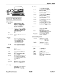
MODEL
NUMBER
9! 7.372480
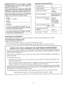
SPECIFICATIONS
HORSEPOWER:
5.0
DISPLACEMENT:
12.04 cu. in.
GASOLINE CAPACITY:
1 quart
(Unleaded)
OIL (20 oz. Capacity):
SAE 30 (Above 32°F)
5W30 (Below 32°F)
SPARK PLUG (GAP .030 in.):
(0.76 mm)
Champion
RJ19LM or
Sears z_ 33312
or STD 361458
or STD 360950
VALVE CLEARANCE:
.008 in.
.008 in.
SERIAL
NUMBER
DATE OF
PURCHASE
THE MODEL AND SERIAL NUMBERS WILL BE
FOUND ON A DECAL ATTACHED TO THE REAR
OF THE LAWN MOWER HOUSING.
YOU SHOULD RECORD BOTH SERIALNUMBER
AND DATE OF PURCHASE AND KEEPtN A SAFE
PLACEFORFUTUREREFERENCE.
MAINTENANCE
SOLID STATE IGNITION
AIR GAP:
.0!25 in,
BLADE BOLT TORQUE:
35-40 ft.-Ibs,
AGREEMENT
A Sears Maintenance Agreement is available on this product.
CUSTOMER
Intake:
Exhaust:
Contact your nearest Sears store for details.
RESPONSIBILITIES
• Read and observe the safety rules.
. Follow a regular schedule in maintaining, caring for and using your lawn mower.
Follow the instructions
under "Customer Responsibilities"
LIMITED TWO YEAR WARRANTY
and "Storage" sections of this OwneCs Manual
ON CRAFTSMAN
POWER MOWER
For two years from date of purchase, when this Craftsman Lawn Mower is maintained, lubricated, and tuned up
according to the operating and maintenance instructions in the owner's manual, Sears wilt repair free of charge any
defect in material or workmanship.
If this Craftsman Lawn Mower is used for commercial or rental purposes, this warranty applies for only 90 days from
the date of purchase.
This Warranty does not cover:
.
Expendable items which become worn during normal use, such as rotary mower blades, blade adapters, belts,
air cleaners and spark plug.
•
Repairs necessary because of operator abuse or neg!igence, including bent crankshafts and the failure to
maintain the equipment according to the instructions contained in the owner's manual.
WARRANTY SERVICE IS AVAILABLE BY RETURNING THE CRAFTSMAN POWER MOWER TO THE NEAREST
SEARS SERVICE CENTER/DEPARTMENT IN THE UNITED STATES. THIS WARRANTY APPLIES ONLY WHILE
THIS PRODUCT iS IN USE IN THE UNITED STATES.
This Warranty gives you specific legal rights, and you may also have other rights which vary from state to state.
SEARS, ROEBUCK AND CO., D/731CR-W SEARS TOWER, CHICAGO, IL 60684
3
TABLE OF CONTENTS
SAFETY RULES .............................................
2
PRODUCT SPECIFICATIONS
........................ 3
CUSTOMER RESPONSIBILITIES
...... 3, 12-14
WARRANTY
...................................................
3
LAWN MOWER ACCESSORIES
................... 5
ASSEMBLY
....................................................
6
OPERATION ...................................................
7
SERVICE AND ADJ USTM ENTS .................. 15
STORAGE .....................................................
17
TROUBLESHOOTING
..................................
27
REPAIR PARTSLAWN MOWER ......... 18-22
REPAIR PARTS - ENGINE ...................... 23-25
PARTS ORDERING/SERVICE.
BACK COVER
INDEX
A
Accessories ............................................
Adjustments:
Carburetor ..................................
Drive Control Cable ...................
Handle Height ............................
Height of Cut ................................
Air Filter:
Service ........................................
5
16
15
16
9
14
Assembly:
Handle ..........................................
6
Grass Catcher .............................. 6
B
Blade:
Sharpening ................................. 13
Replacement .............................. !3
C
Controls:
Operator Presence Control Bar .7
Drive Control ............................... 7
Customer Responsibilities
..... 3, 12-14
Air Filter ......................................
14
Blade Care/Replacement
..........
Drive Wheels ..............................
Engine ........................................
Gear Case ...................................
Lubrication .................................
Spark Plug .................................
E
Engine:
OH Change .................................
Oil LeveJ .....................................
Oil Type ......................................
Starting .......................................
Storage .......................................
13
13
14
13
12
!4
14
14
14
10
17
F
Fuel:
Type ............................................
Storage .......................................
P
10
17
H
Handle:
Adjustment ................................. 16
Assembly ..................................... 6
L
Lubrication:
Engine ........................................
12
Brake Spring Bracket ................ 12
Rear Door Hinge ........................ 12
Handle Bracket Mounting Pin .. 12
Wheel Adjuster .......................... 12
M
Maintenance Agreement .................... 3
Maintenance Schedule ..................... 12
Mowing Tips .......... ,........................... 11
Mulching!Mowing Tips ....... ,............. !1
0
Oil:
Engine ........................................
10
Storage ....................................... 18
Operation:
Operating Lawn Mower ............... 7
Drive Control ................................ 9
Operator Presence Control Bar ......... 7
Options:
Attachments ................................. 5
Repair Parts
Lawn Mower .................. ........ 18-22
Engine ...................................
R
Responsibilities,
Customer
23-25
....3, 12-14
S
Safety Rules ........................................
Service and Adjustments:
Carburetor ..................................
Drive Control Cable ...................
Drive Belt ...................................
Engine Speed ............................
Handle ........................................
Spark Plug .........................................
Specifications
.....................................
Starting the Engine ..........................
Stopping the Engine ........................
Storage ..............................................
T
2
16
15
15
16
16
14
3
t0
10
17
Trouble Shooting Chart ................... 27
W
Warranty ..............................................
Wheels:
Wheel Adjusters ..........................
3
7
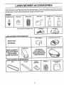
ACCESSORIES
These accessories were available when this lawn mower was produced. They are also available at most Sears retail outlets,
catalog and service centers. Most Sears stores can also order repair parts for you, when you provide the model number' of
your lawn mower. Some of these accessories may not apply to your lawn mower.
ENGINE
_
SPARK PLUG
MUFFLER
AIR FILTER
GAS CAN
ENGINE OiL
STABiLiZER
if lawn mower is an electric start
LAWN MOWER
PERFORMANCE
CLiPPiNG DEFLECTOR
DUST SHIELD
REAR BAG
OPTIONAL
SiDE DISCHARGE CATCHER
FABRIC BAG
REPLACEMENT
BAG FOR REAR
DISCHARGE
LAWN MOWERS
LAWN MOWER
BELT
OPTIONAL
CATCHER FOR
SIDE DISCHARGE
LAWN MOWER
MAINTENANCE
BLADE
BLADE
ADAPTER
5
WHEELS
LAWN MOWER
COVER
BLY
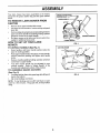
Your lawn mower has been assembled at the factory
except for the grass catcher bag and the grass catcher
frame.
TO REMOVE
CARTON
UPPER HANDLE
LAWN MOWER FROM
*
o
Remove loose parts included with mower.
Cut down two end corners of carton and lay end panel
down flat.
*
Remove all packing materials except padding between
upper and lower handle and padding holding operator
presence control bar to upper handle.
Roll lawn mower out of carton and check carton thoroughly for additional loose parts.
*
OPERATOR PRESENCE
CONTROL BAR
LIFT UP
MOWING POSITION
LOWERHANDLE
HOW TO SET UP YOUR LAWN
MOWER
TO UNFOLD
*
=
o
HANDLE
FiG. 1
CATCHERFRAME
(See Fig. 1)
Raise handles until tower handle section locks into
place in mowing position.
Raise upper handle section intoplace on lower handle,
remove protective padding and tighten both handle
knobs.
Remove handle padding holding operator presence
control bar to upper handle.
Your lawn mower handle can be adjusted for your
mowing comfort.
Refer to "Adjust Handle" in the
Service and Adjustment section of this manual.
TO ASSEMBLE
GRASS
\
FRAME OPENING
CATCHER
(See Fig. 2)
-
FiG. 2
Put grass catcher frame intograss bag with stiff part of
bag on the bottom.
Slip vinyl bindings over frame.
NOTE: If vinyl bindings are too stiff, hold them in warm
water for a few minutes, if bag gets wet, let it dry before
using.
6
OPERATION
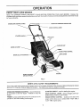
KNOW YOUR LAWN MOWER
READ THIS OWNER'S MANUAL AND SAFETY RULES BEFORE OPERATING YOUR LAWN MOWER. Compare the
illustrations with your lawn mower to familiarize yourself with the location of various controls and adjustments. Savethis manual
for future reference.
ENGINE ZONE CONTROL
OPERATOR PRESENCE CONTROL BAR
CABLE
DRtVE CONTROL LEVER
STARTER
HANDLE
GASOUNECAP
GRASSCATCHER
PRIMER
,ENGINESPEED CONTROL
DRIVE COVER
ENGINE OIL CAP W/DIPSTICK
HOUSING
WHEELADJUSTER
(ON EACH WHEEL)
FIG, 3
MEETS CPSC SAFETY REQUIREMENTS
Sears rotary walk-behind power lawn mowers conform to the safety standards of the American National Standards Institute
and the U.S. Consumer Product Safety Commission. The blade turns when the engine is running.
STARTER HANDLE - used for sta_ing the engine.
OPERATOR PRESENCE CONTROL - must be held down
to the handle to start the engine, Release to stop the
engine,
DRIVE CONTROL LEVER o used to engage power-pro.pelled forward motion of lawn mower.
ENGINE SPEED CONTROL - located on the side of the
PRIMER- pumps additional fuel from the carburetor to the
cylinder for use when starting a cold engine.
engine which a!lows you to select either "HIGH" (_)
"LOW" (._) engine speed.
7
or
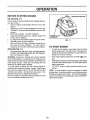
OPERATION
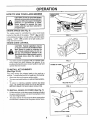
HOW TO USE YOUR LAWN MOWER
ENGINESPEED
CONTROL
LEVER
_
CAUTION: Do notrunyourlawn mower
without muicher plate in place and door
closed or without an approved clipping
deflector
or graescatcher
in place.
Never attempt
to operate the lawn
mower with the rear door removed or
propped open,
ENGINE
SPEED
(See Fig. 4)
The engine speed is controlled by a !ever (red knob)
located on the side of the engine. "HIGH" ('_IY) position
is for starting the engine, normal cutting, and better grass
bagging. "LOW" (_)
position is for I ght cutting trimming and fuel economy.
ENGINE
ZONE
FIG, 4
\
CONTROL
CAUTION: Federal regulations require
an engine control to be installed on this
lawn mower in order to minimize the
risk of blade contact injury. Do net under any circumstances attempt to defeat the function of the operator centre!,
The blade turns when the engine is
running.
-
Your lawn mower
ence control bar
positioned behind
operate the lawn
REAR DOOR
FIG. 5
is equipped with an operator preswhich requires the operator to be
the lawn mower handle to start and
mower.
TO iNSTALL ATTACHIVlENTS
(See Figs. 5 & 6)
Your lawn mower was shipped ready to be used as a
mulcher. To install attachments for bagging or discharging:
,
,
Open rear door and remove mulcher plate.
You can now install catcher or optional clipping deflector,
"To return to mu!ching operation reverse the above
steps. BE SURE MULCHER PLATE IS INSTALLED
BEFORE USING FOR MULCHING OPERATION.
TO INSTALL
•
GRASS
CATCHER
FIG. 6
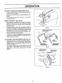
(See Fig. 7)
Liftthereardooronthelawnmowerhousingandplace
the grass catcher frame onto the formed up tabs on the
rear door hinge bracket.
The grass catcher is secured to the !awn mower when
the rear door is lowered onto the grass catcher frame,
HINGE
/:/
)OOR
GRASSCATCHERFRAME
FiG. 7
8
OPERATION
TO EMPTY
•
°
,
GRASS
CATCHER
(See Fig. 8)
To remove grass catcher, release operator presence
control bar to stop engine.
Lift up rear door and remove the grass catcher by the
handle.
Do not drag the bag when emptying;
unnecessary wear.
DRIVE CONTROL
it will cause
(See Fig. 9)
•
Self-propelling is controlled by holding the operator
presence control bar down to the handle and pushing
the drive control lever forward until it clicks; then
release the lever.
•
Forward motion wilt stop when the operator presence
control bar is released. To stop forward motion without
stopping engine, release the operator presence control
bar slightly unti! the drive control disengages. Hold
operator presence control bar down to handle to continue mowing without self-propelling.
To keep drive control engaged when turning corners,
push down on handle and lift front wheels off ground
while turning lawn mower.
•
TO ADJUST
•
•
,
CUTTING
HEIGHT
FIG. 8
OPERATORPRESENCE
CONTROLBAR
(See Fig. 10)
Raise wheels for low cut and lower wheels for high cut.
Wheels are set in low cut for shipping. Adjust cutting
height to suit your requirements. Medium position is
best for most lawns,
To change cutting height, squeeze adjuster lever toward wheel. Move wheel up or down to suit your
requirements. Be sure all wheels are in the same
setting.
DRIVECONTR__
FiG. 9
LOWER WHEELS
FOR HIGH CUT
RAISE WHEELS
FOR LOW CUT
FIG, 10
OPERATION
BEFORE
STARTING
ENGINE
GA,_OLINE RLLER CAP
OIL (See Fig. 11)
A 20 oz. bottle of Pennzoil SAE 30 oil is included with your
new lawn mower.
Remove engine oil cap and fill to the FULL !ine on the
dipstick.
*
Use 20 ozs. of oil For type and grade of oil to use, see
"ENGINE" in Customer Responsibilities section of this
manual.
.
POUR OIL SLOWLY. DO NOT OVER FILL.
*
Check oil level before each use. Add oil if needed. Fill
to FULL line on dipstick.
*
To read proper level, tighten engine oil cap each time.
o
Reinstall engine oil cap and tighten.
°
After the first two (2) hours of mowing, change the oil,
and every 25 hours thereafter.
You may need to
change the oil more often under dusty, dirty conditions.
ENGINE OIL CAP
W/DiPSTICK
FIG. 11
TO START ENGINE
GAS (See Fig. 11)
,
To start a cold engine, push primer five (5) times
before trying to start. Use a firm push. This step is not
usually necessary when starting an engine which has
already run for a few minutes.
Fill gasoline tank with fresh, clean unleaded gasoline.
DO NOT USE PREMIUM GASOLINE. BE CAREFUL
NOT TO OVER FILL TANK.
WARNING: Experience indicates that alcohol blended
fuels (called gasohol or using ethanol or methanol) can
attract moisture which leads to separation and formation of
acids during storage. Acidic gas can damage the fuel
system of an engine while in storage.
To avoid engine problems, the fuel system should be
emptied before storage for30 days or longer. Drain the gas
tank, start the engine and let it run until the fuel lines and
carburetor are empty. Use fresh fuel next season. See
Storage instructions for additional information.
Never use engine or carburetor cleaner products in the fuel
tank or permanent damage may occur.
•
Push engine speed control lever to HIGH (,_)
tion.
•
Hold operatorpresence control bar down to the handle
and pull starter handle quickly. DO NOT allow starter
rope to snap back.
To "STOP" engine, release operator presence control bar.
•
posi-
NOTE: In cooler weather it may be necessary to repeat
priming steps. In warmer weather over priming may cause
flooding and engine will not start. If you do flood engine,
wait a few minutes before attempting to start and DO NOT
repeat priming steps.
10
OP
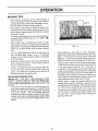
MOWING
ATION
TIPS
•
Under certain conditions, such as very tall grass, it
may be necessary to raise the height of cut to reduce
pushing effort and to keep from overloading the engine and leaving clumps of grass clippings.
•
For extremely heavy cutting, reduce the width of cut
and raise the rear of the lawn mower housing one (1)
wheel adjuster setting higher than the front for better
discharge o_ grass.
For better grass bagging and most cutting conditions,
the engine speed should be set in the '"HIGH" (_)
(FAST) position.
°
When using a rear discharge lawn mower in moist,
heavy grass, clumps of cut grass may not enter the
grass catcher. Reduce ground speed (pushing speed)
and/or run the lawn mower over the area a second
time.
•
If a trail of grass clippings is left on the right side of a
rear discharge lawn mower, mow in a clockwise
direction with a small overlap to collect the clippings
on the next pass.
•
Keep top of engine around starter clear and clean of
grass clippings and chaff. This will help engine air
flow and extend engine life.
FiG, 12
*
Avoid cutting your lawn when it is wet. Wet grass
tends to form clumps and interferes with the mulching
action. The best time to mow your lawn is the early
afternoon. At this time the grass has dried and the
newly cut area will not be exposed to the direct sun.
,
For best results, adjust the lawn mower cutting height
so that the lawn mower cuts off only the top one-third
of the grass blades (See Fig. 12). If the lawn is
overgrown it will be necessary to raise the height of cut
to reduce pushing effort and to keep from overloading
the engine and leaving clumps of mulched grass. For
extremely heavy mulching, reduce your width of cut,
mow slowly and raise the rear of the lawn mower one
wheel adjuster setting higher than the front.
o
Certain types of grass and grass conditions may
require that an area be mulched a second time to
completely hide the clippings. When doing a second
cut, mow across or perpendicular to the first cut path.
,
Change your cutting pattern from week to week. Mow
north to south one week then change to east to west
the next week. This will help prevent matting and
graining of the lawn.
Pores in cloth grass catchers can become filled with
dirt and dust with use and catchers will collect less
grass. To prevent this, regularly hose catchers off
with water and tet dry before using.
MULCHING
MOWING
TIPS
IMPORTANT:
FOR BEST PERFORMANCE,
KEEP
MOWER HOUSING FREE OF BUILT-UP GRASS AND
TRASH. CLEAN AFTER EACH USE. SEE "CLEANING"
IN CUSTOMER RESPONSIBILITIES SECTION OF THIS
MANUAL.
The special mulching blade will recut the grass clippings many times and reduce them in size so that as
they fall onto the lawn they will disperse into the grass
and not be noticed.
Also, the mulched grass will
biodegrade quickly to provide nutrients for the lawn.
Always mulch with your highest engine (blade) speed
as this will provide the best recutting action of the
blades.
11
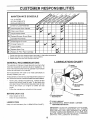
CUSTO
MAINTENANCE
RESPONSi
LITIES
SCHEDULE
FILL tN DATES
AS YOU COMPLETE
REGULAR SERVICE
Check for Loose Fasteners
MI
Ot
WI
El
RI
Clean/Inspect Grass Catcher
Clean Lawn Mower
Inspect Mower Blade
Replace/Sharpen
Mower Blade
Lubricate Pivot Points
Check Engine Oil Level
Change Engine Oil
Inspect Muffler
NI
Et
Replace Spark Plug
Replace Air Filter Paper Cartridge
1 ° Change more often when operating under a heavy load or in high ambient temperatures.
2 - Service more often when operating in dirty or dusty conditions.
3 _ Replace blades more often when mowing in sandy soil.
GENERAL
LUBRICATION
RECOMMENDATIONS
The warranty on this lawn mower does not cover items that
have been subjected to operator abuse or negligence. To
receive full value from the warranty, operator must maintain
mower as instructed in this manual.
CHART
I WHEEL
ADJUSTER
Some adjustments will need to be made periodically to
properly maintain your unit.
All adjustments in the Service and Adjustments section of
this manual should be checked at least once each season.
•
Once a year, replace the spark plug, replace air filter
element and check blade for wear. A new spark plug
and clean/new air filter element assures proper air-fuel
mixture and helps your engine run better and last
longer.
Follow the maintenance schedule in this manual.
BEFORE
•
EACH
BRAKE SPRING
BRACKET
USE
HANDLE BRACKET
MOUNTING PIN
Check engine oil level.
Check for loose fasteners.
LUBRICATION
Keep unit well lubricated (See "LUBRICATION
CHART"),
_(_) REAR DOOR
HINGE
(_
SPRAY LUBRICANT
(_
_
30 MOTOROiL REFER TO ENGINE =CUSTOMER
RESPONSIBIL_IES SECTION,
iMPORTANT:
DO NOT OiL OR GREASE PLASTIC WHEEL
BEARINGS,
VISCOUS
LUBRICANTS
WiLL ATTRACT
DUST AND D_RT THAT WiLL SHORTEN
THE LIFE OF
THE SELF LUBRICATING
BEARINGS.
IF YOU FEELTHEY
MUST BE LUBRICATED,
USE ONLY A DRY, POWDERED
GRAPHITE
TYPE LUBRICANT
SPARINGLY,
12
CUSTOMER
RESPONSI
LITIES
LAWN MOWER
Always observe safety rules when performing any maintenance.
TIRES
Keep tires free of gasoline, oil, or insect control chemicals which can harm rubber,
Avoid stumps, stones, deep ruts, sharp objects and
other hazards that may cause tire damage.
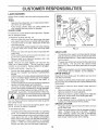
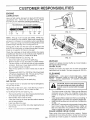
BLADE
CARE
For best results, mower btade must be kept sharp. Replace
bent or damaged blades.
[_
_LLBOLT
CRANK-
SHAFT
KEYWAY
To keep your drive system working properly, the gear
case and area around the drive should be kept clean
and free of trash build-up. Clean under the drive cover
twice a season,
,
•
The gear case is filled with lubricant to the proper level
at the factory, The only time the lubricant needs
attention is if service has been performed on the gear
case.
if lubricant is required, use only Texaco Starplex Premium Grease, part no, 750355. Do not substitute,
DRIVE WHEELS
Check front drive wheels each time before you mow to be
sure they move freely.
The wheels not turning freely means trash, grass cuttings,
etc. are in the drive wheel area and must be cleaned to free
drive wheels,
If necessary to clean the drive wheels, check both front
wheels.
•
•
•
•
•
replacement blade to get the
NOTE: We do not recommend sharpening
you do, be sure the blade is balanced,
BLADEADAPTER
GEAR CASE
A _oose bJade can be dan-
Use only Sears authorized
best cutting results,
LOCKWASHER
FIG. 13
TO REPLACE BLADE (See Fig, !3)
•
Position the blade adapter on the engine crankshaft.
Be sure key in adapter and keyway in crankshaft are
aligned,
Position blade on the blade adapter aligning the two (2)
holes in the blade with the raised lugs on the adapter.
Be sure the word TOP (stamped on the blade) is
toward the engine,
Install the blade bolt with the lock washer and hardened
washer into blade adapter and crankshafL
Use block of wood between blade and lawn mower
housing and tighten the blade bolt, turning clockwise.
•
The recommended tightening torque is 35-40 ft. Ibs.
IMPORTANT: BLADE BOLT IS GRADE 8 HEAT TREATED.
CAUTION:
gerous.
SHAFT
CRANKBLADE
TO REMOVE BLADE (See Fig. 13)
Remove spark plug wire from spark plug and place
wire where it cannot come in contact with spark plug.
Turn lawn mower on its side. Make sure air filter and
carburetor are up.
Use a wood block between blade and mower housing
to prevent blade from turning when removing blade
bolt,
Protect your hands with gloves and/or wrap blade with
heavy cloth.
Remove blade bolt by turning counter-clockwise. Use
a 9/16" box or open-end wrench,
Remove blade and attaching hardware (bolt, lock
washer and hardened washer).
NOTE: Remove the blade adapter and check the key
inside hub of blade adapter. The key must be in good
condition to work properly, Replace adapter if damaged.
Remove hubcaps, hairpin cotters and washers.
Remove wheels from wheel adjusters,
Remove any trash or grass cuttings from inside the
dust cover, pinion and/or drive wheel gear teeth.
Put wheels back in place.
If after cleaning, the drive wheels do not turn freely,
contact your nearest Sears Service Center.
GRASS
blade .. but if
•
TO SHARPEN BLADE
•
The blade can be sharpened with afite or on a grinding
wheel, Do not attempt to sharpen while on the mower.
To check blade balance, drive a nail into a beam or wa!l,
Leave about one inch of the straight nail exposed.
Place center hole of blade over the head of the nail, If
blade is balanced, it sho'..'!d remain in a horizontal
position, If either end of the blade moves downward,
sharpen the heavy end until the blade is balanced,
!3
CATCHER
The grass catcher may be hosed with water, but must
be dry when used.
Check your grass catcher often for damage or deterioration, Through normal use it will wear. If catcher
needs replacing, replace only with a manufacturer
approved replacement catcher from Sears. Give the
lawn mower model number when ordering,
CUSTO
L TIES
ENGINE
LUBRICATION
S
Use only high quality detergent oil rated with APi service
classification SG. Select the oit's SAE viscosity grade
according to your expected operating temperature.
RECOMMENDED
SAE VISCOSITY
GRADES
__,
°F -20 °
0°
32 °
60 °
80 °
100 °
°C-29 °
-18 °
0°
t6 °
27 °
38 °
CONTAINER
F_G. 14
COLLAR
NOTE: Although mu!ti-viscosity oils (5W30, 10W30 etc,)
improve starting in cold weather, these multi-viscosity oils
will result in increased oil consumption when used above
32°F. Check your' engine oi! level more frequently to avoid
possible engine damage from running low on oi!.
TURN
COUNTER*
CLOCKWISE
TO REMOVE
Change the oil after the first two hours of operation and
every 25 hours thereafter or at least once a year if the lawn
mower is not used for' 25 hours in one year.
SLOT
Check the crankcase oil level before starting the engine
and after each five (5) hours of continuous use. Tighten oil
plug securely each time you check the oil level,
TURN CLOCKWISE
TO TIGHTEN
AiR FILTER COVER
FIG, 15
TO CHANGE ENGtNE OiL (See Fig. 14)
Disconnect spark plug wire from spark plug,
Remove engine oil cap; lay aside on a clean surface.
Tip lawn mower on its side and drain oil into a suitable
container. Rock lawn mower back and forth to remove
any oil trapped inside of engine,
Wipe off any spilled oil on lawn mower and on side of
engine.
Fill engine with SAE 30 or 10W 30 oil. All oil must meet
API service classification SG. Fill only to the "FULL"
line on the dipstick. DO NOT OVER FILL.
o Replace engine oil cap.
Reconnect spark plug wire to spark plug,
MUFFLER
Inspect and replace corroded muffler as it could create a
fire hazard and/or damage,
SPARK
Change your spark plug each year to make your engine
start easier and run better. Set spark plug gap at .030 inch.
CLEANING
IMPORTANT:
FOR BEST PERFORMANCE,
KEEP
MOWER HOUSING FREE OF BUILT-UP GRASS AND
TRASH. CLEAN UNDERSIDE OF MOWER HOUSING
AFTER EACH USE,
AIR FILTER
CAUTION: Disconnect spark plug wire
from spark plug and place wire where it
cannot come in cor_tact with the spark
Your engine will not run properly and may be damaged by
using a dirty air filter.
Replace the air filter every year, more often if you mow in
very dusty, dirty condkions. Do not wash air filter.
o
TO CHANGE AIR FILTER (See Fig, 15)
,
•
,
PLUG
Remove the aiHiker cover by turning counterclockwise
to the stop and putt away from collar.
Remove filter from inside of cover.
Clean the inside of the cover and the collar to remove
•
°
any dirt accumulation,
Insert new filter into cover,
Put air filter cover and filter into collar aligning the tab
with the slot.
•
Push in on cover and turn clockwise to tighten.
Turn lawn mower on its side. Make sure air filter and
carburetor are up_ Clean the underside of your lawn
mower by scraping to remove build-up of grass and
trash,
Clean engine often to keep trash from accumulating, A
clogged engine runs hotter and shortens engine life,
Keep finished surfaces and wheels free of all gasoline,
oil, etc.
We DO NOT recommend using a garden hose to clean
lawn mower unless the electrical system, muffler, air
filter and carburetor are covered to keep water out.
Water in engine can result in shortened engine life.
CLEAN
14
t
UNDER
DRIVE COVER
Clean under drive cover at teast twice a season. Scrape
underside of cover with putty knife or similar tool to remove
any build-up of trash or grass on underside of drive cover.
SERVICE AND ADJUSTMENTS
CAUT_©N:
BEFORE PERFORMING
ANY SERVICE OR ADJUSTMENTS:
•
Release control bat.
o
Make sure the blade and all moving parts have completely stopped.
,
Disconnect
spark plug wire from spark plug and place where it cannot come in contact
with plug,
LAWN MOWER
TO ADJUST
CUTTING
See "TO ADJUST CUTTING
section of this manual.
DISCHARGE
HEIGHT
HEIGHT" in the Operation
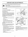
GUARD
The discharge guard, attached to the discharge opening of
your lawn mower, is provided to prevent the possibility of
injury resulting from objects being thrown out of the discharge opening into the operator mowing position. If the
discharge guard becomes damaged, it should be replaced.
TO REMOVE/REPLACE
(See Fig. 16)
•
,
•
•
o
,
PRESS
DRIVE BELT
FiG, !6
Remove drive cover. Remove bett by pushing down
on gear case putley.
Turn tawn mower on its side with carburetor and fuel
cap up.
Remove blade.
Remove debris shield.
•
o
,
•
o
PUER$
SHiFteR _._)
J Ill
o.,vo
CABLE
_
AR
A drive control cable that needs adjustment will keep your
lawn mower from self-propelling properly and can also
cause gear case components to wear out sooner.
•
Remove drive cover.
o
JAM NUT"C"-_
JAM NUT "B". "_%_.SLEEVE_
Remove belt from engine pulley on crankshaft.
Install new belt by reversing above steps,
Always use factory approved belt to assure fit and
long life.
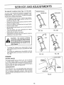
TO ADJUST DRRVE CONTROL
(See Fig. 17')
,
•
_
CLUTCH
SPRING
SCREW "A"
ADJUSTING
BRACKET
FJGo 17
Loosen cable clamp screw "A" and nuts "B" and "C".
Hold down operator presence control bar to handle
and engage drive control.
Move shifter arm to drive position while rotating front
wheels to be sure jaw clutch is engaged. Pull threaded
sleeve with p_iers. Do not pull on control cable.
Tighten nut "C" until steeve is snug.
Tighten screw"A" and nut"B".
Push lawn mower back and forth to be sure gear case
is engagedl
Replace drive cover.
Release operator presence control bar.
REAR DEFLECTOR
The rear deflector, attached between the rear wheels of
your lawn mower, is provided to minimize the possibility
that objects will be thrown out the rear of the lawn mower
into the operator's mowing position.
If the rear deflector
replaced.
15
becomes
damaged,
it should be
SERVICE AND ADJUSTMENTS
TO ADJUST
HANDLE
(See Figs,
18 Thru
20)
SHiPPiNG
Your lawn mower handle can be raised or lowered for your
mowing comfort. Four (4) positions are available: high,
medium high, medium low and low, Handles are shipped
mounted in the medium low position.
o
•
°
•
,
POSITION
MEDIUM LOW
To change from medium low to medium high position,
the upper and lower handle sections will have to be
turned over (See Fig. 18B).
Remove the controls and operator presence control
bar from the upper handle,
Remove the starter rope guide from the tower handle.
Remove hairpin cotters.
Disconnect the lower handle from the hand!e brackets
(See Fig. 20).
Turn the handle over and reassemble the hairpin
cotters that have been removed.
MEDIUM HiGH
FIG. 18B
FiG, 18A
Reassemble the starter rope guide.
Reassemble the controls and the operator presence
control bar to the upper handle.
LOW
CAUTION:
The operator
presence
control bar must pivot freely to permit
blade brake engagement when contro_
bar is released. Do not over t{ghten the
fasteners holding the controls to the
upper handle.
•
,
To change from medium
upper handle section will
Fig, 19A)_
To change from medium
lower handle section wil!
Fig, 19B).
HIGH
low to high position only the
have to be turned over (See
low to tow position, only the
have to be turned over (See
FIG. 19A
FiG. 19B
ENGINE
LOWER HANDLE
ENGINE SPEED
Your engine speed has been factory set, Do not attempt
to increase engine speed or it may result in personal
injury. If you believe that the engine is running too fast or
too slow, take your lawn mower to an authorized Sears
Service Center for repair and adjustment.
CARBURETOR
HANDLE
BRACKET
Your carburetor has a non-adjustable fixed main jet for
mixture control. If your engine does not operate properly
due to suspected carburetor problems, take your lawn
mower to an authorized Sears Service Center for repair and
adjustment,
FiG, 20
16
STORAGE
ENGINE
Immediately prepare your lawn mower for storage at the
end of the season or if the unit wilt not be used for 30 days
or more.
FUEL SYSTEM
IMPORTANT:
IT IS IMPORTANT TO PREVENT GUM
DEPOSITS FROM FORMING IN ESSENTIAL
FUEL
SYSTEM PARTS SUCH AS CARBURETOR, FUEL FILTER,
FUEL HOSE, OR TANK DURING STORAGE.
ALSO,
EXPERIENCE INDICATES THAT ALCOHOL BLENDED
FUELS (CALLED GASOHOL OR USING ETHANOL OR
METHANOL) CAN ATTRACT MOISTURE WHICH LEADS
TO SEPARATION AND FORMATION OF ACIDS DURING
STORAGE.
ACIDIC GAS CAN DAMAGE THE FUEL
SYSTEM OF AN ENGINE WHILE IN STORAGE.
•
Drain the fue! tank.
LAWN MOWER
When lawn mower is to be stored for a period of time, clean
it thoroughly, remove all dirt, grease, leaves, etc. Store in
a clean, dry area.
,
Clean entire lawn mower (See "CLEANING" in the
Customer Responsibilities section of this manual).
,
Lubricate as shown in the Customer Responsibilities
section of this manual.
•
Be sure that all nuts, bolts, screws, and pins are
securely fastened. Inspect moving parts for damage,
breakage and wear. Replace if necessary.
•
Touch up all rusted or chipped paint surfaces; sand
lightly before painting.
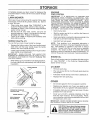
HANDLE
(See Fig. 21)
You can fold your lawn mower handle for storage.
•
•
Loosen upper handle mounting bolts enough to allow
upper handle to be folded back.
IMPORTANT:
WHEN FOLDING THE HANDLE FOR
OR TRANSPORTATION,
BE SURE
TO
FOLD
,
Never use engine or carburetor cleaner products in the
fuel tank or permanent damage may occur.
•
Use fresh fuel next season.
ENGINE OiL
THE HANDLE AS SHOWN OR YOU MAY DAMAGE THE
CONTROL CABLES.
•
Start the engine and let it run until the fuel lines and
carburetor are empty.
NOTE:
Fuel stabilizer is an acceptable alternative in
minimizing the formation of fuel gum deposits during storage. Add stabilizer to gasoline in fuel tank or storage
container. Always follow the mix ratio found on stabilizer
container. Run engine at least 10 minutes after adding
stabilizer to allow the stabilizer to reach the carburetor. Do
not drain the gas tank and carburetor if using fuel stabilizer.
Squeeze the bottom ends of the lower handle toward
each other until the lower handle clears the handle
bracket, then move handle forward.
STORAGE
•
Drain oii (with engine warm) and replace with clean engine
oil. (See "ENGINE"
in the Customer Responsibilities
section of this manual).
When setting up your hand!e from the storage position,
the lower handle will automatically lock into the mowing position.
CYLINDER
LOWER HANDLE
•
Remove spark plug.
Pour one ounce (29 m!) of oil through spark plug hole
into cylinder.
HANDLE
BRACKET
•
Pull starter handle slowly a few times to distribute oil.
,
Replace with new spark plug.
OTHER
HAIRPIN
COTTER
OPERATOR PRESENCE
CONTROLBAR
•
Do not store gasoline from one season to another.
•
Replace your gasoline can if your can starts to rust.
Rust and/or dirt in your gasoline will cause problems.
•
tf possible, store your unit indoors and cover it to give
protection from dust and dirt.
•
Cover your unit with a suitable protective cover that
does not retain moisture. Do not use plastic. Plastic
cannot breathe which al!ows condensation to form and
will cause your unit to rust.
IMPORTANT: NEVER COVER MOWER WHILE ENGINE
AND EXHAUST AREAS ARE STILL WARM.
UPPER HANDLE
FOLDFORWARD
FORSTORAGE
FOLD BACKWARD
MOWING
POSITION
CAUTION: Never store the lawn mower
with gasoline in the tank inside a building where fumes may reach an open
flame or spark. Allow the engine to cool
before storing in any enclosure.
LOWER HANDLE
FiG. 21
17
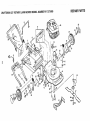
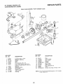
0RAFTSMAN
REPAIR PARTS
22" ROTARY LAWN MOWER MODEL NUMBER 917.372480
!
\
9
27
11
35
58
62
55
12
29
28
54
47
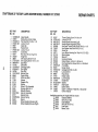
CRAFTSMAN
22" ROTARY LAWN MOWER MODEL NUMBER 917.372480
KEY PART
NO. NO
1
2
3
4
5
6
7
8
9
!0
1!
!2
14
15
16
17
20
21
22
23
24
25
26
27
28
29
30
31
32
34
35
36
133088X479
130861
STD522515
STD541425
85827
63688
STD541425
851509
48137
750328
36953
STD512505
88644X479
133189
133190X417
87596X479
128796
133170X479
85543
87677
77400
85179
52160
87748
84921
62335
85021X004
87877
850855X004
84920
850923
850924
DESCRIPTION
Upper Handle
Engine Zone Control Cable
Hex Head Bolt 1/4-20 x 1-1/2
Locknut 1/4-20
Cable Clip
Handle Knob
Locknut 1/4-20
Controt Bar
Rear Door Kit (Incl. Key#10)
Hinge Rod
Self Tapping Screw #10-24
Hex Tapping Screw 1/4-20 x 1/2
Back Plate
Side Baffle
Discharge Baffle
Rear Baffle
Rear Skirt
Mulcher Plate
Engine Pulley
Hi-Pro Key #505
Hubcap
Retainer Clip
Washer
Wheel & Tire Assembly
Shoulder Bolt 3/8-16
Belleville Washer
Axle Arm Assembly
Selector Knob
Selector Spring
Spacer
Wheel Adjusting Bracket (Left)
Wheel Adjusting Bracket (Right)
REPAIR PARTS
KEY PART
NO. NO
DESCRIPTION
37
38
39
40
41
42
43
44
46
47
48
49
50
51
52
54
55
56
57
58
59
60
61
62
64
-=
Thread Cutting Screw 5/t6-18 x 3/4
Locknut 5/16-18
Handle Bracket Assembly (Left)
Handle Bracket Assembly (Right)
Hex Head Thread Roiling Screw 3/8-16 × 1-1/8
Hex Washer Head Screw #10-24 x 1/2
Guide Clip
Lawn Mower Housing (Incl. Key #14,15,5t &52)
Blade Adapter
Blade 22"
Hardened Washer
HeJical Washer 3/8-24 x 1-3/8 Grd. 8
Hex Head Machine Screw 3/8-24 x 1 -,3/8 Grd. 8
Front Baffle
Danger Decal
Carriage Bolt 5/16-18 x 5/8
Locknut 3/8-16
Hinge Screw
Hairpin Cotter
Lower Handle
Handle Boit
Washer
Rope Guide
Debris Shield
Engine- Craftsman - Model No. 143.424!52
Owner's Manual
55187
STD541431
86912X417
86913X417
850998
750097
87930
48273
851514
752234
851074
850263
851084
87587X479
85463
STD533107
751592
88652
51793
84676X479
131959
85t201X004
103672X
134612
132961
134078
Available accessories not included with lawn mower:
• 71 33303
Clipping Deflector
7_!133623
Gas Can (2.5 gal.)
7_!_133500
Fuel Stabilizer
7_!_33300
SAE 30W Oil (20 oz.)
7_.!.33417
Dust Shield
71 33316
Mower Cover
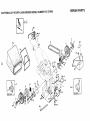
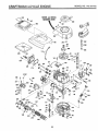
REPAIR PARTS
,,.RAFTSMAN 22" ROTARY' LAWN MOWER MODEL NUMBER 917.372480
7
/
5
54
I
11
13
20
18
2O
21
\
35-"
15
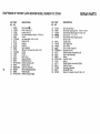
CRAFTSMAN
=,a},
REPAIR PARTS
22" ROTARY LAWN MOWER MODEL NUMBER 917.372480
KEY PART
NO. NO.
DESCRiPTiON
KEY PART
NO. NO
DESCRIPTION
1
2
3
4
5
6
7
8
9
t0
1!
12
13
14
15
16
t7
18
19
20
21
23
Drive Head _
Drive Control L_,_
Locknut #10-24
Pan Head Machine Screw #10-24 × 2
V-Belt
Hex Head Bolt 1/4-20 x 2o3/4
Retainer Clip
Hubcap
Washer
Nylon Bushing
Wheel & Tire Assembiy 8.00 x 2.00
E-Ring
Pinion
Dust Cover
Spacer Bearing
Belleville Washer
Selector Spring (Left)
Selector Knob
Axle Arm Assembly
Wheel Adjusting Bracket
Retaining Clip
Selector Spnng (Right)
25
26
27
28
29
751031
87866
750097
30
31
_
_
34
35
36
37
38
40
41
52
54
55
56
83700
132010
431-482
4826_c
_STD_0014
48175
48281
83632
STD541425
75192
48!74
88614
751663
86012
851552
Drive Cover Decal
Pan Head Tapping Screw #1 0-24 x 2-3/4
Hex Washer Head Screw #10-24 × 3/'4
Drive Cover "_2_ _-_,__/
He× Washer Head Tapping Screw
#10-24 × 3/8
Cable Clamp
Hex Flange Nut
Drive Pulley
Drive Control Cable Kit
Woodruff Key #3
Wheel Adjuster Assembly (Left)
Gear Case Assembly
Spring
Locknut !/4-20
Spring
Wheel Adjuster Assembly (Right)
Catcher Frame
Grassbag Assembly
Driveshaft Cover
Screw, Pan Head, Hi-Lo #10-16 x 1/2
48029
133049
74189
750029
83691
74760444
85!79
77400
52160
86960
87729
12000003
74507
76401
86273
86274
851019X004
87877
88284X004
850922
58922
851021X004
750108
REPAIR PARTS
22 °' POWER- PROPELLED
LAWN MOWER 917.372480
GEAR CASE ASSEMBLY PART NUMBER 132232
¢
17
7,
15
22
KEY PART
NO. NO.
!
2
3
4
5
6
53838
85178
131483
57072
57388
48032
7
8
9
10
11
12
77881
77039
750430
57079
131484
131485
DESCRIPTION
Locknut, Keps 1/4-20
Bracket, Adjusting
Shifter
Seal
Pin, Grooved 1/8 x 1/2
Gear Case Halves, Upper and
Lower (includes Key #4, 5 and 7)
Bearing
Bracket, Spring
Drive Shaft
Washer, Hardened
Yoke, Clutch
Bushing
KEY PART
NO. NO,
DESCRIPTION
13
14
15
16
17
18
19
20
21
22
Plug
Gear, Helical
Jaw, Clutch
Grease
E-Ring
Key, Hi-Pro
Shaft, Worm
Key, Woodruff, #3
Worm
Screw, Hex Head 1/'4-20 x 1-1/4
86447
133804
750436
750355
STD581050
850848
131481
65692
83680
STD522512
NOTE: All component dimensions given in U.S. inches
1 inch : 25.4 mm
22
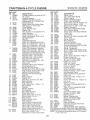
CRAFTSMAN 4-CYCLE ENGINE
MODEL
NO.143.424tS2
L
/
23
CRAFTSMAN 4..CYCLE ENGINE
REF
NO,
1
2
6
7
PART
NO.
33968B
26727
33734
342!4A
8
9
33735
30200
12A
12B
14
15
16
17
18
19
20
30
40
33886
34695
28277
30589
31383A
31335
650548
31361
32600
35801
34535
34536
34537
4!
33662B
33563B
33564B
42
43
45
46
48
50
52
69
70
72
73
33567
33568
33569
20381
32875
32610A
27241
33553
29914
35261
34311C
30572
28833
75
80
81
82
83
84
86
89
90
92
93
!00
101
103
27897
30574
30590A
30591
30588A
29193
650488
611004
611109
650815
650816
34443A
610118
650814
110
119
120
125
34961
33554A
34342
29313C
29315C
29314B
29315C
t26
130 6021A
135 35395
MODEL
NO.143.424152
REF
NO.
150
151
t66
169
172
174
178
182
184
185
!86
189
DESCRIPTION
Cylinder Assembly (Includes #2, 20)
Pin, Dowel
Element, Breather
Breather Assembly (Includes
Reference #6, 8, 9, 12Aand 12B)
* Gasket, Breather
Screw, Sems, Hex Washer Head,
Self-Tapping #10-24 x 9/16
Tube, Breather
Elbow, Breather Tube
Washer, Fiat
Rod, Governor (includes Ref. #14)
Lever, Governor
Clamp, Governor Lever
Screw, HexWasher #8-32 x 5/16
Spring, Extension
Seal, Oil
Crankshaft Assembly
Piston, Pin & Ring Assembly, Std.
Piston, Pin & Ring Assy..010" over
Piston, Pin & Ring Assy..020" over
(Assemblys Include #41,42 and 43)
Piston & Pin Assembly, Standard
Piston & Pin Assembly .010" over
Piston & Pin Assembly .020" over
(Assemblys Include Reference #43)
Ring Set, Piston, Standard Size
Ring Set, Piston .010" oversize
Ring Set, Piston .020" oversize
Ring, Piston Pin Retaining
Rod Assy., Connecting (Incl. #46)
Bolt, Connecting Rod
Valve, Lifter
Camshaft, Mech. Comp. Release
Pump Assembly, Oil
* Gasket, Mounting Flange
Flange, Mount. (Inc!. #72,73,75,80)
Plug, Oil Drain (Includes Ref. #73)
Gasket, Oil Drain Plug (Not
Required with Plastic Oil Plug)
Seal, Oil
Shaft, Governor
Washer, Flat
Gear Assy., Governor (Incl. #81)
Spool, Governor
Ring, Retaining
Screw, Sems, Hex 1/4-20 x 1-1/4
Key, Flywheel
Flywheel
Washer, Betlevilie
Nut, Flywheel
Solid State Assembly
Cover, Spark Plug
Screw, Sems, Torx %15, Hex
Washer Head #10_24 x 1
Wire, Ground
* Gasket, Cylinder Head
Head, Cylinder
Valve, Exhaust, Standard Size
Valve, Exhaust, 1/32" oversize
Valve, Intake, Standard Size
Valve, htake, 1/32" oversize (Atl
Valves Include Reference #t 51)
Screw, Hex Flange 5/16o!8 x lq/2
Spark Plug, Resistor Type
(Champion RJ-19LM or Equivalent)
PART
NO.
31672
31673
35827
27234A
32755
650128
29752
6201
26756
31384A
34358
650839
DESCRIPTION
Spring, Valve
Cap, Lower Valve Spring
Shroud, Engine
* Gasket, Valve Spring Box
Cover, Valve Spring Box
Screw, Seres, Hex Hd. #10-24 x 1/2
Nut and Lock Washer 1/4-28
Screw, Hex Hd., Cap 1/4-28 x 7/8
* Gasket, Carburetor
Pipe, Intake (Includes Ref, #224)
Link, Governor Spring
Screw, Seres, Hex Head, Powerlok
1/4-20 x 3/8
Lever, Brake
190 35831
191 35039B
Bracket, S.E. Brake (Includes #195)
Link, Control
192 34966
t93 34965
Spring, Extension
194 32309
Ring, Retaining
195 610973
Terminal Assembly
Bracket Assembly, Control
200 35727
(Includes Reference #202 thru 205)
202 33802
Spring, Compression
203 31342
Spring, Compression
Screw, Fillister Head #5-40 x 7/16
204 650549
205 650777
Screw, Fillister Head #6-32 x 21/32
Link, Throttle
207 34336
Knob, Control
215 35511
Screw, Sems, Hex Head 1/4-20 x I
223 650451
224 34690A
* Gasket, Intake Pipe
Screw, Hex Washer Head,
238 650932
Shoulder #10_32 x 49/64
* Gasket, Air Cleaner
239 34338
241 35797
Collar, Air Cleaner
245 35066
Filter, Air Cleaner, Paper
250 35065
Cover, Air Cleaner
260 35826
Housing, Blower
262 650831
Screw, Hex Washer Head,
Powerlok Thread 1/4-20 x 15/32
263 35821
Grill Assembly, Recoil
275 34613
Muffler Assembly (includes #277)
276 33753
Plate, Lock
277 650795
Screw, Hex Head 1/4-20 x 2-1/4
285 35000
Hub, Starter
287 650884
Screw, Hex Wash. Hd. #8-32 x 1/2
Line, Fuel
290 34357
292 26460
Clamp, Fuel Line
300 35586
Tank Assy. (includes #292 & 301)
301 35355
Cap, Fuel
305 35819A
Tube, Oil Fill (includes Ref. #309)
306 34265
* Gasket, Fil! Tube
"O" Rin q
307 35499
Screw, "Rex Washer Head,
309 650936
Shoulder #10-32 x 13/32
310 35822
Dipstick, Oit Fill
3t3 34080
Spacer, Flywheel Key
347 650898
Screw, Hex Washer Head,
Shoulder #10-32 x 27/32
370 35840
Decal, Name
370C 35167
Decal, Instruction
380 632078A
Carburetor (includes Ref. #184)
390 590637
Starter, Rewind
400 35997
Gasket Set (lnci. items marked *)
RPM Setting: Low Speed: 2450-2750, High: 2900-3200
*indicates Parts Included in Gasket Set, Reference #400
NOTE: All component dimensions given in U.S. inches
1 inch = 25.4 mm
24
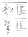
CRAFTSMAN 4-CYCLE ENGINE
MODEL
NO.143,424152
CARBURETOR
NO.632078A
!
I
27
REF PART
NO. NO.
DESCRIPTION
1
2
4
5
6
7
16
25
27
28
29
30
31
35
40
44
48
Throttle Shaft and Lever Assembly
Throttle Return Spring
Dust Seal Washer
Dust Seal
Throttle Shutter
Throttle Shutter Screw
Fuel Fitting
Float Bowl
Float Shaft
Float
"O" Ring, Float Bowl to Body
inlet Needle, Seat & C!ip (tncl, #31)
Spring Clip
Primer Bulb/Retainer Ring
High Speed Bowl Nut
Bowl Nut Washer
Welch Plug, Atmospheric Vent
631615
631767
631184
631971
631616
650506
632527
631700
631024
632019
631028
631021
631022
632047
632071
631334
631027
NOTE: All component dimensions given in U.S. inches
1 inch = 25.4 mm
'
3O
31
",4
REWIND STARTER
NO. 590637
10
REF PART
NO. NO.
DESCRiPTiON
-1
2
3
4
5
6
7
8
9
10
1!
12
!3
Starter, Rewind
Pin, Spring (includes Reference #4)
Washer
Retainer
Washer
Spring, Brake
Dog, Starter
Spring, Dog
Pulley
Spring, Rewind
Cover, Spring
Housing Assembly, Starter
Rope, Starter (98" long, 9/64" dia.)
Handle, Starter
590637
590599
590600
590615
590601
590598
590616
590617
590618
590619
590620
590638
590535
590452
NOTE:
25
All component dimensions given in U.S. inches
1 inch = 25.4 mm
SERVICE NOTES
26
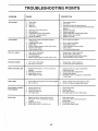
TROUBLESHOOTING
POINTS
PROBLEM
CAUSE
Does not start
1.
2.
3.
4.
Dirty air filter.
Out of fuel.
Stale fuel.
Water in fuel.
1.
2.
3.
4.
Clean/replace air filter.
Fill fuettank.
Drain tank and refill with fresh clean fuel.
Drain fuel tank and carburetorand refill tank with fresh
5.
6.
7.
8.
9.
Spark plug wire is disconnected.
Bad spark plug.
Loose blade or broken blade adapter.
Control bar in released position
Control bar defective
5.
8.
7.
8.
9.
gasoline.
Connect wire to plug.
Replace spark plug.
Tighten blade bolt or replace blade adapter.
Depress control bar to handle.
Replace control bar.
1.
1.
Set in "Higher Cut" position.
2.
3.
4.
5.
6.
Rear of lawn mower housing/blade dragging
in heavy grass.
Cutting too much grass.
Dirty air filter.
Buildup of grass, leaves and trash under mower.
Too much oil in engine.
Walking speed too fast.
2.
3.
4.
5.
Set in "Higher Cut" position.
Clean/replace air filter.
Clean underside of mower housing.
Check oil level.
6.
Cut at slower walking speed.
1.
2.
3_
4.
Worn, bent or loose blade.
Wheel heights uneven.
Low engine speed.
Buildup of grass, leaves, and trash under mower.
1.
2.
3.
4.
Replace blade. Tighten blade bolt.
Set all wheels at same height.
Set engine speed control in HiGH position.
Clean underside of mower housing.
1.
2.
Replace blade. Tighten blade bolt.
Contact Sears Service Department.
Depress control bar to upper handle before
pulling starter rope.
Contact Sears Service Department.
Replace blade adapter.
Move lawn mower to cut grass or to hard surface
to start engine.
Loss of power
Poor cut - uneven
Excessive vibration
CORRECTION
1.
Worn, bent or loose blade.
2.
Bent engine crankshaft.
1.
Engine flywheel brake is on when control bar is
released.
1.
2.
3.
4.
Bent engine crankshaft
Blade adapter broken.
Blade dragging in grass.
2.
Loss of drive
1.
2.
Drive wheels not turning with drive control engaged.
Belt not driving.
1.
2.
Adjust or replace drive control cable, if broken.
Put belt on pulleys or replace belts if broken.
Grass catcher not filling
(If so equipped)
1.
2.
Cutting height too low.
Lift on blade worn off.
3.
4.
Catcher not venting air.
Low engine speed.
1.
2.
3.
4.
Raise cutting height.
Replace blade.
Clean grass catcher.
Set engine speed control in HIGH position.
1.
2.
1.
2.
3.
Grass is too high or wheel height is too low.
Rear of lawn mower housing/blade dragging
in grass.
Grass catcher too full.
4.
Handle height position not right for you.
Raise
Raise
setting
Empty
Adjust
Starter rope hard to pull
Hard to push
3.
4.
27
3.
4.
cutting height.
rear of lawn mower housing one (1)
higher.
grass catcher.
handle height to suit.
®
S_FA/ S
OWNER'S
MANUAL
5.0 HORSEPOWER
22" REAR DISCHARGE
2 in ONE Mulcher/Bagger
POWER PROPELLED
ROTARY LAWN MOWER
Each Lawn Mower has its own model number.
engine has its own model number.
MODEL NO.
917.372480
Each
The model number for your lawn mower will be found on
a decal attached to the rear of the lawn mower housing.
The model number for the engine will be found on the
Blower Housing of the engine adjacent to the spark plug.
All parts listed here in may be ordered through Sears,
Roebuck and Co. Service Centers and most Retail
Stores.
WHEN ORDERING REPAIR PARTS, ALWAYS GIVE THE
FOLLOWING INFORMATION:
• PRODUCT - "ROTARY LAWN MOWER"
• MODEL NUMBER- 917'.372480
° ENGINE - CRAFTSMAN - MODEL NO. 143.424152
HOW TO ORDER
REPAIR PARTS
• PART NUMBER
• PART DESCRIPTION
Your Sears merchandise has added value when you
consider that Sears has service units nationwide
staffed with Sears trained technicians...professional
technicians specifically trained on Sears products,
having the parts, tools and the equipment to insure that
we meet our pledge to you, we service what we sell.
134078
Rev. 2
'11
02/27/92
Printed in U.S.A.
II I_1
I
IIII IIIIIII
II
I1"1
U