1
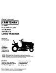
Owner's Manual
CRnFTSMnN
o
20.0 HP
ELECTRIC START
50" MOWER
AUTOMATIC
GARDEN TRACTOm
Model No.
917.273060
•
•
•
•
Safety
Assembly
Operation
Maintenance
• Repair Parts
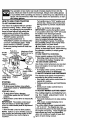
CAUTION:
Read and follow all
Safety Rules and Instructions
before operating this equipment.
For answers to your questions
about this product, Call:
1-800-659-5917
Sears Craftsman Help Line
5 am- 5 pm, Mon- Sat
Seam, Roebuck and Co,, Hoffman Estates, IL 60179
Maintenance .........................................
....
.......
19
Service and Adjustments ...................... 23
Storage .................................................
31
Troubleshooting ....................................
32
Repair Parts .........................................
36
Parts Ordering ....................... Back Cover
.8
.......... 12
.......... 19
CRAFTSMAN RIDING EQUIPMENT
purchase, if this Craftsman Riding Equipment is mainto the instructionsin the owner's manual,
any parts found to be defective in material or
during normal use, such as blades, spark
plugs,
belts,_stc._
• Tire replacement or repair caused by punctures from outside objects, such as nails,
thoms, stumps, or glass.
• Repairs necessary because of operator abuse, negligence, improper storage or accident or the failure to maintain the equipment according to the instructionscontained in
the owner's manual.
• Riding equipment used for commercial or rental purposes.
LIMITED 90 DAY WARRANTY ON BATTERY
For ninety (90) days from date of purchase, if any battery included with this riding equipment proves defective in material or workmanship and our testing determines the battery will not hold a charge, Sears will replace the battery at no charge. In-home warranty
service on your Craftsman riding equipment is available at no charge for 30 days from
the date of purchase. Please contact your nearest service center. After 30 days from the
date of purchase, warranty service is available by taking your Craftsman riding equipment to your nearest Sears Service Center. (In-home warranty service will still be available after 30 days from the date of purchase but a standard trip charge will apply). This
warranty applies only while this product is in the United States. This Warranty gives you
specific legal rights, and you may also have other rights which may vary from state to
state.
Sears, Roebuck and Co., 1:)/817WA, Hoftman Estates, IL 60179
GENERAL
-
OPERATION-
• Never carry passengers.
• Do not mow in reverse unless absolute-
Read, understand, and follow all instructions in the manual and on the machine
ly necessary. Always look down and
behind before and while backing.
• Be aware of the mower discharge direction and do not point it at anyone. Do
not operate the mower without either
the entire grass catcher or the guard in
place.
• Slow down before turning.
• Never leave a running machine unattended. Always turn off blades, set parking brake, stop engine, and remove
keys before dismounting.
before starting.
• Only allow responsible adults, who are
familiar with the instructions, to operate
the machine.
• Clear the area of objects such as rocks,
toys, wire, etc., which could be picked
up and thrown by the blade.
• Be sure the area is clear of other people
beforemowing.
St_op machine if anyone
enters the area.
2
• Do nottry to stabilize the machine by
putting your foot on the ground.
• Do not use grass catcher on steep
slopes.
• Turn off blades when not mowing.
• Stop engine before removing grass
catcher or unclogging chute.
• Mow only in daylight or good artificial
light.
• Do not operate the machine while under
the influence of alcohol or drugs.
• Watch for traffic when operating near or
crossing roadways.
• Use extra care when loading or unloadingthe machine into a trailer or truck.
CHILDREN
Tragic accidents can occur if the operator
is not alert to the presence of children.
Children are often attracted to the
machine and the mowing activity. Never
assume that children will remain where
you last saw them. ,
• Keep children out of the mowing area
and under the watchful care of another
SLOPE OPERATION
Slopes are a major factor related to lossof-control and tipover accidents, which
can result in severe injury or death. All
slopes require extra caution. If you cannot
back up the slope or if you feel uneasy on
it, do not mow it.
DO:
• Mow up and down slopes, not across.
• Remove obstacles such as rocks, tree
limbs, etc.
• Watch for holes, ruts, or bumps. Uneven
terrain could overturn the machine. Tall
grass can hide obstacles.
• Use slow speed. Choose a low gear so
that you will not have to stop or shift
while on the slope.
• Follow the manufacturer's recommendations for wheel weights or counterweights to improve stability.
• Use extra care with grass catchers or
other attachments. These can change
the stability of the machine.
• Keep all movement on the slopes slow
and gradual. Do not make sudden
changes in speed or direction.
• Avoid starting or stopping on a slope. If
tires lose traction, disengage the blades
and proceed slowly straight down the
slope.
DO NOT:
• Donotturn on slopes unless necessary,
and then, turn slowly and gradually
downhill, if possible.
• Do notmow near drop-offs, ditches, or
embankments. The mower could suddenly turn over if a wheel is over the
edge of a cliff or ditch, or if an edge
caves in.
• Do not mow on wet grass. Reduced
lraction could cause sliding.
responsible adult.
• Be alert and tum machine off if children
enter the area.
• Before and when backing, look behind
and down for small children.
• Never carry children. They may fall off
and be seriously injured or interfere with
safe machine operation.
• Never allow children to operate the
machine.
• Use extra care when approaching blind
comers, shrubs, trees, or other objects
that may obscure vision.
SERVICE
• Use extra care in handling gasoline and
other fuels. They are flammable and
vapors are explosive.
Use only an approved container.
Never remove gas cap or add fuel
with the engine running.Allow engine to cool before refueling. Do not
smoke.
Never refuel the machine indoors.
Never store the machine or fuel
container inside where there is an
open flame, such as a v_aterheater.
• Never run a machine inside'a closed
area.
• Keep nuts and bolts, especially blade
attachment bolts, tight and keep equipment in good condition.
their proper
operation
regulady.
_ Check
Never tamper
with safety
devices.
Keep machine free of grass, leaves, or
other debris build-up. Clean oil or fuel
spillage. Allow machine to cool before
storing.
• Stop andinspect the equipment if you
strike an object. Repair, if necessary,
before restarting.
3
• Never make adjustments or repairswith
the engine running.
• Grass catcher components are subject
to wear, damage, and deterioration,
which could expose moving pads or
allow objects to be thrown. Frequently
check components and replace with
manufacturer's recommended parts,
when necessary.
• Mower blades are sharp and can cut.
Wrap the blade(s) or wear gloves, ahd
use extra caution when servicing them.
• Check brake operation frequently.
Adjust and service as required.
• Be sure the area is clear of other people
before mowing. Stop machine if anyone
enters the area.
• Never carry passengers.
• Do not mow in reverse unless absolutely necessary. Always look down and
behind before and while backing.
• Never carry children. They may fall off
and be seriously injured or interfere with
safe machine operation.
• Keep children out of the mowing area
and under the watchful care of another
responsible adult.
• Be alert and turn machine off if children
enter the area.
• Before and when backing, look behind
and down for small children.
• Mow up and down slopes (15 ° Max), not
• Remove obstacles such as rocks, tree
limbs, etc.
• Watch for holes, ruts, or bumps. Uneven
terrain could overtum the machine. Tall
grass can hide obstacles.
• Use slow speed. Choose a low gear so
that you will not have to stop or shift
while on the slope.
• Avoid starting or stopping on a slope. If
tires lose traction, disengage the blades
and proceed slowly straight down the
slope.
• Do nottum on slopes unless necessary,
and then, tum slowly and gradually
downhill, if possible.
across.
A Loel_for this symbol to point dut important safety precautions. It means:CAUTION!t! BECOME AWARE!i! YOUR SAFETY IS INVOLVED.
_,CAt.n3ON:
AWARNING:
The engine exhaust from
this product contains chemicals known to
the State of Califomia to cause cancer,
birth defects, or other reproductive harm.
In order to preyenf acciden-
tal starling when setting up, t_ansporting,
adjustingor making repairs always disconnect spark plug wire and place wi_'ewhere
it cannot contact spark plug.
4
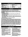
PRODUCT
SPECIFICATIONS
!GASOLINE
iCAPAC TY
!/_ND TYPE:
DIL TYPE
_,PI-SF/SG/SH):
MAINTENANCE
3.5 GALLONS
UNLEADED
REGULAR
A Sears Maintenance Agreement is available on this product. Contact your nearest
Sears store for details.
SAE 10W-30
CUSTOMER
(above 32°F)
SAE 5W-30
DIL CAPACITY:
W/FILTER:
4.2 PINTS
W/O FILTER: 3.7 PINTS
SPARK PLUG:
SAP: .030")
3ROUND SPEED
Champion RC12YC
MPH):
tIRE PRESSURE:
REVERSE:
2.1
FRONT: 14 PSI
REAR: 10 PSI
FORWARD:
15AMPS@
nance" and "Storage" sections
owner's manual.
3600 RPM
AMP/HR:
35
MIN. CCA:
280
CASE SIZE: U1R
BLADE BOLT
TORQUE:
27-35 FT. LBS.
of this
_,WARNING:
This tractor is equipped
with an intemal combustion engine and
should not be used on or near any unimproved forest-covered,
brush-covered or
grass-covered land unless the engine's
exhaust system is equipped with a spark
arrester meeting applicable local or state
laws (if any). If a spark arrester is used, it
should be maintained in effective working
order by the operator.
In the state of California the above is
5.8
BATTERY:
RESPONSIBIUTIES
• Read and observe the safety rules.
• Follow a regular schedule in maintaining, caring for and using your tractor.
• Follow the instructions under "Mainte-
(below 32°F)
3HANGING
SYSTEM:
AGREEMENT
required by law (Section 4442 of the
Califomia Public Resources Code). Other
states may have similar laws. Federal
laws apply on federal lands. A spark
arrester for the muffler is available through
your nearest Sears, Authorized Service
Center (See REPAIR PARTS section of
this manual).
CONGRATULATIONS on your purchase
of a Craftsman Tractor. It has been
designed, engineered and manufactured
to give you the best possible dependability
and performance.
Should you experience any problem you
cannot easily remedy, please contact your
nearest Sears Authorized Service Center.
We have competent, well-trained technicians and the proper tools to service or
repair this tractor.
Please read and retain this manual. The
instructionswill enable you to assemble
and mair_tainyour tractor properly. Always
observe the =SAFETY RULES".
5
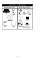
PARTS BAG CONTENTS
SHOWN FULL SIZE
(1) Shoulder Bolt
5/16-18
©
(1) Knob
(1) Washer
17/32 x 1-3/16 x 12 Gauge
i
-
(E_oubl_Loop)
R_tair_erSprings
1_3)
I
(4) Retainer Springs
(Single Loop)
6
Paris packet separately in carton
Parts Bag contents not shown full size
7--
(_
b
(2) Shoulder
V,
Bolts
Seat
Video
(2) Keys
@
(2)
Washers
3/8,
x 7/8
x 14 Ga.
(2) Centerlock
Nuts
(2) Gauge
Wheels
Cassette
i
i
i
I
o
i
Manual
Steering
Sleeve
Steering
Wheel Insert
Steering Wheel
Steering Sleeve
Extension
=L
Parts Bag
Slope Sheet
_
(2) FrontLinkAseemb_lee
7
Yournewtractorhas beenassembledatthe factorywithexceptionof those partsleft
unassembledfor shippingpurposes.Toensuresafe andproperoperationofyour tractor
all partsandhardwareyou assemblemustbe tightenedsecurely.Usethe correcttools
as necessaryto insurepropertightness.Reviewthe videocassettebeforeyou begin.
TOOLS REQUIRED FOR
ASSEMBLY
A socket wrench set will make assembly
easier. Standard wrench sizes you need
are listed below.
(1) 9/16" wrench
(1) 3/4" Socket w/
(1) 1/2" wrench
drive ratchet
(1)Pliers
(1) Phillips Screw(1) Utility knife
driver
(1) Tire pressure gauge
Steering
When right or left hand is mentioned in
this manual, it means, from your point of
view, when you are in the operating position (seated behind the steering wheel).
Steering
Wheel
Wheel
Adapter
TO REMOVE TRACTOR FROM
CARTON
UNPACK
CARTON
• Remove all accessible loose parts and
parts boxes from shipping carton (See
page 6).
• Cut, from top to bottom, along lines on
all four comers of shipping carton, and
lay panels flat.
• Remove mower and package materials.
Check for any additional loose parts or
boxes and remove.
IMPORTANT: Check for and remove any
staples in skid that may puncture tires
where tractor is to roll off skid.
BEFORE ROLLING TRACTOR OFF
SKID
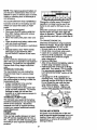
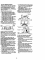
ATTACH STEERING WHEEL
• Remove hex bolt, lockwasher and large
flat washer from steering shaft.
• Position front wheels of the tractor so
they are pointing straight forward.
• Slide the steenng sleeve over the steering shaft.
• Ah'_gn
tabs and press steering sleeve
extension into bottom of steedng wheel.
TO ROLL TRACTOR OFF SKID (See
Operation section for location and
function of controls)
• Press lift lever plunger and raise attachment lift lever to its highest position.
• Release parking brake by depressing
clutch/brake pedal.
• Place freewheel control in freewheeling
position to disengage transmission (See
"TO TRANSPORT"
in the Operation
section of this manual).
• Roll tractor forward off skid.
are horizontal (left to dght) and slide
Position
steering
wheel
so cross bars
onto steering
wheel
adapter.
Secure steering wheel to steering shaft
with hex bolt, lock washer and large fiat
washer previously removed. Tighten
securely.
• Snap steering wheel insert into center
of steering wheel.
• Remove protective materials from trac• tor hoed and grill.
8
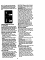
HOW TO SET UP YOUR
CHECK BATTERY
CHECK TIRE PRESSURE
The tires on your tractor were ovednflated
at the factory for shipping purposes.
Correct tire pressure is important for best
cutting performance,
• Reduce tire pressure to PSI shown in
"PRODUCT SPECIFICATIONS" section
of this manual.
TRACTOR
• Lift hood to raised position.
• If this battery is put into service after
month and year indicated on label (label
located between terminals) charge battery for minimum of one hour at 6-10
amps. (See "BATTERY" in Maintenance
section of this manual for charging
instructions).
CHECK BRAKE SYSTEM
After you learn how to operate your tractor, check to see that the brake is propedy
adjusted. See "TO ADJUST BRAKE" in
the Service and Adjustments section of
this manual.
_t
,"
_'°
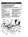
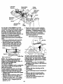
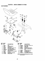
INSTALL MOWER AND DRIVE BELT
Be sure tractor is on level surface and
mower suspension arms are raised with
attachment lift control (see Know Your
Tractor in Operation section). Engage
parking brake.
• Cut and remove ties secudng anti-sway
bar and belts. Swing anti-sway bar to
left side of mower deck,
• Slide mower under tractor with dis-
Label
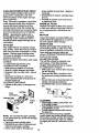
INSTALL
SEAT
Adjust seat before tightening adjustment
knob.
charge guard to dght side of tractor.
IMPORTANT:
Check belt for proper routing in all mower pulley grooves. Install
belt into electdc clutch pulley groove.
• Remove cardboard packing on seat
pan.
• Place seat on seat pan and assemble
shoulder bolt. Tighten shoulder bolt
securely.
• Assemble adjustment knob and flat
washer loosely. Do not tighten.
• Lower seat into operating position and
sit on seat.
• Install one front link in top hole of the
left hand front mower bracket and left
hand front suspension bracket. Retain
with two single loop retainer springs as
shown.
• Install second front link in dght hand
front suspension bracket and retain with
single loop retainer spdng as shown.
• Slide dght side of mower back and
install link in top hole of right hand front
mower bracket. Retain with single loop
retainer spdng as shown.
•Tum
height adjustment knob counter°
clockwise until it stops.
• Lower mower linkage with attachment
lift control.
• Slide seat until a comfortable position is
reached which allows you to press
clutch/brake pedal all the way down.
• Get off seat without moving its adjusted
position.
• Raise_seat and tighten adjustment knob
securely.
Seat
Seat Pan
• Place the suspension arms on outward
pointing deck pins. If necessary, rock
and raise front of mower to align deck
pins with the holes in suspension arms.
Retain with double loop retainer spdngs
with loops down as shown.
• Connect anti-sway bar to chassis bracket under left footrest and retain with
double loop retainer spring.
•Tum
height adjustment knob clockwise
to remove slack from mower suspension.
Shoulder
Bolt
Flat Washer
Adjustment Knob
9
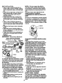
CHECK FOR PROPER
ALL BELTS
• Raise deck to highest position.
• Assemble gauge wheels as shown
using long shoulder bolts, 3/8 washers,
and 3/8-16 center Iocknuts. Tighten securely.
• Adjust gauge wheels before operating
mower as shown in the Operation section of this manual.
PosmoN
OF
See the figures that are shown for replacing motion, mower drive, and mower blade
drive belts in the Service and Adjustments
section of this manual. Vedfy that the
belts are routed correctly.
CHECK MOWER LEVELNESS
For best cutting results, mower should be
properlyleveled. See =TO LEVEL
MOWER HOUSING" in the Service and
Adjustments section of this manual.
Double Loop
Retainer Spring
(Inward pointing deck
pins)
Chassis
Bracket
Double Loop
Retainer Spring
Front
Links
Front
Suspension
Brackets
Suspension
Arms
Left Hand
Gauge
Wheel Bar
Single Loop
Retainer Springs
Bolt
Gauge
Wheel
3/8 Washer
Use Rlera For
Retainer Springs
3/8-16
Center
Locknut
Bracket
Anti-Sway
Bar
Discharge
Idler
Pulley
10
Ii CHECKLIST
Please review the following checklist:
/ All assembly instructionshave been
completed.
,/No remaining loose parts in carton.
,/Battery is properly prepared and
charged. (Minimum 1 hour at 6 amps).
,/Seat is adjusted comfortably and tightened securely.
,/All tires are properly inflated. (For shipping purposes, the tires were overinflated at the factory).
,/Be sure mower deck is propedy leveled
side-to-side/front-to-rear for best cutting
results. ('13resmust be properly inflated
for leveling).
,/Check mower and drive belts. Be sure
they are routed properly around pulleys
and inside all belt keepers.
,/Check wiring. See that all connections
are still secure and wires are properly
clamped.
•/ Before driving tractor, be sure freewheel
control is in drive position.
While learning how to use your tractor,
pay extra attention to the following important items:
,/Engine oil is at proper level.
,/Fuel tank is filled with fresh, clean, regular unleaded gasoline.
,/Become familiar with all controls - their
location and function. Operate them
before you start the engine.
,/Be sure brake system is in safe operating condition.
•/ It is important to purge the transmission
before operating your tractor for the first
time. Follow proper starting and transmission purging instructions(See "TO
START ENGINE" and =PURGE TRANSMISSION" in the Operation section of
thismanual).
11
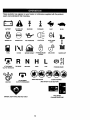
Thesesymbolsmay appearon your tractoror in literaturesuppliedwiththe product.
Learnandunderstandtheir meaning.
BATTERY
CAUTION OR
WARNING
REVERSE
ENGINE ON
ENGINE OFF
OIL PRESSURE
FORWARD
FAST
SLOW
LIGHTS ON
®
FUEL
CHOKE
MOWER HEIGHT
PARKING BRAKE
LOCKED
UNLOCKED
MOWER LIFT
r 'l R N H L
ATTACHMENT
CLUTCH ENGAGED
REVERSE
NEUTRAL
AI-rACHMENT
IGNITION
HIGH
LOW
KEEP AREA CLEAR
PARKING BRAKE
SLOPE HAZARDS
(SEE SAFETY RULES SECTION)
CLUTCH DISENGAGED
FREE WHEEL
(AutomaticModelsonly)
DANGER, KEEP HANDS AND FEET AWAY
12
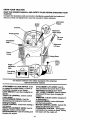
KNOW YOUR TRACTOR
READ THIS OWNER'S
TRACTOR
MANUAL
AND SAFETY
RULES
BEFORE
OPERATING
YOUR
Compare the illustrations with your tractor to familiarize yourself with the locations of
various controls and adjustments. Save this manual for future reference.
Ignition
Switch
Light Switch
Position
Attachment
Clutch Switch
Throttle Control
Lift Lever
Plunger
Clutch/Brake
Pedal
Uft Lever
Choke
Control
- Parking Brake
Control
Lever
Height
Adjustment
Knob
Free Wheel
Our tractors conform to the safety standards of the American
National Standards Institute.
ATTACHMENT CLUTCH SWITCH: Used
to engage the mower blades, or other attachments mounted to your tractor.
UGHT SWITCH: Turns the headlights on
and off.
THROTTLE CONTROL: Used to control
engine speed.
CLUTCH/BRAKE PEDAL: Used for
declutching and braking the tractor and
starting the engine.
CHOKE CONTROL: Used when starting a
cold engine.
HEIGHT ADJUSTMENT KNOB: Used to
adjust the mower cutting height.
IGNITION-SWITCH: Used for starting and
stopping the engine.
ATTACHMENT
LIFT LEVER: Used to
raise and lower the mower deck or other
attachments mounted to your tractor.
LIFT LEVER PLUNGER: Used to release
attachment lift lever when changing its
position.
AMMETER:
Indicates battery charging (+)
or discharging (-).
PARKING BRAKE: Locks clutch/brake
into the brake position.
MOTION CONTROL LEVER. Selects the
speed and direction of the tractor.
FREEWHEEL
CONTROL - Disengages
transmission for pushing or slowly towing
the tractor with the engine off.
13
The operation of any tractor can result in foreign objects thrown into the
J
eyes, which can result in severe eye damage. Always wear safety glasses
or eye shields while operating your tractor or performing any adjustments or
repairs. We recommend a wide vision safety mask over spectacles, or standard safety glasses.
I
HOW TO USE YOUR TRACTOR
Turn ignition key to =OFF" position and
remove key. Always remove key when
leaving tractor to prevent unauthorized
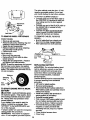
TO SET PARKING BRAKE
Your tractor is equipped with an operator
presence sensing switch. When engine
is running, any attempt by the operator to
leave the seat without first setting the
parking brake will shut off the engine.
• Depress clutch/brake pedal into full
"BRAKE" position and hold.
• Place parking brake lever in
.......
"ENGAGED" position and release pressure from clutch/brake pedal. Pedal
should remain in "BRAKE" position.
Make sure parking brake will hold tractor secure.
Push-In to
Throttle
Control
Attachment Clutch
Switch Pull Out To
use.
• Never use choke to stop engine.
IMPORTANT: Leaving the ignition switch
in any position other than =OFP will cause
the battery to be discharged (dead).
NOTE: Under certain conditions when
tractor is standing idle with the engine running, hot engine exhaust gases may
cause =browning" of grass. To eliminate
this possibility, always stop engine when
stopping tractor on grass areas.
_,
CAUTION:
Always stop tractor com-
pletely, as described above, before leaving
the operator's position; to empty grass
catcher, etc.
TO USE THROTTLE
CONTROL
Always operate engine at full throttle.
• Operating engine at less than full throttle reduces the battery charging rate.
TO USE CHOKE CONTROL
Lever
Parking Brake
Pedal =Drive"
Position
Position
Position
Use choke control whenever you are starting a cold engine. Do not use to start a
warm engine.
• To engage choke control, pull knob out.
Slowly push knob in to disengage.
TO MOVE FORWARD AND BACKWARD
The direction and speed of movement is
controlled by the motion control lever.
• Start tractor with motion control lever in
neutral (N) position.
STOPPING
• Release parking brake and clutch/brake
MOWER BLADES pedal.
• To stop_mower blades, move attach• Slowly move motion control lever to
ment clutch switch to "DISENGAGED"
desired position.
position.
TO ADJUST MOWER CUTTING HEIGHT
GROUND DRIVE The cutting height is controlled by turn• To stopground drive, depress
ing the height adjustment
knob in
clutch/brake pedal into full "BRAKE"
desired direction.
IpO.
sition.
• Move motion control lever to neutral (N)
• Turn knob clockwise (C) to raise cutting
position.
height..
IMPORTANT: The motion control lever
• /urn Knoo counterclockwise (O)to
lower cutting height.
does not retum to neutral (N) position
The cutting height range is approximately
when the clutch/brake pedal is depressed.
1-1/2" to 4-1/2". The heights are meaENGINE sured
from the ground to the blade tip with
• Move throttle control to slow position.
the
engine
not running. These heights are
NOTE:. Failure to move throttle control to
approximate and may vary depending
slow position and allowing engine to idle
up.onsoil conditions, height of grass and
before stopping may cause engine to
=backfire".
14 types of grass being mowed.
• The average lawn should be cut to
approximately 2-1/2 inches during the
cool season and to over 3 inches during
hot months. For healthier and better
looking lawns, mow often and after
moderate growth.
• For best cutting performance, grass
over 6 inches in height should be
mowed twice. Make the first cut relatively high; the second to desired height.
TO ADJUST GAUGE WHEELS
_.CAUTION:
Do not operate the mower
without either the entire grass catcher, on
mowers so equipped, or the discharge
guard in place.
Attachment Clutch
Switch Pull Out To
"Engage"
Gauge wheels are properly adjusted
when they are slightly off the ground when
mower is at the desired cutting height in
operating position. Gauge wheels then
keep the deck in proper position to help
prevent scalping in most terrain conditions.
Push In To
"Disengage"
TO OPERATE
• Adjust gauge wheels with tractor on a
flat level surface.
clutch/brake pedal quickly to brake posif stoppingis
absolutely
push
tion
and engage
parking necessary,
brake.
Move motion control lever to neutral (N)
position.
IMPORTANT: The motion control lever
does not retum to neutral (N) position
when the clutch/brake pedal is depressed.
i
Clevis Pin
sp0og
\ Jj--
auge
Wheels _
ON HILLS
,_CAUTION:
Do not drive up or down
hills with slopes greater than 15 ° and do
not drive across any slope. Use the slope
guide provided at the back of this manual.
• Choose the slowest speed before starting up or clown hills.
• Avoid stopping or changing speed on
hills.
• If slowing is necessary, move throttle
control lever to slower position.
• Adjust mower to desired cutting height.
• Lower mower with lift control. Remove
rear retainer spring and clevis pin which
secure each gauge wheel.
• Lower gauge wheels to ground. Raise
gauge wheels slightly to align holes in
bracket and gauge wheel bar and insert
clevis pins. Gauge wheels should be
slightly off the ground.
• Replace retainer springs into clevis
pins.
Retrainer
Attachment Lift Lever
High Position
Low
.#"Position
Fe_=_'_7///'lT_ _.
parking
and clutch/brake
pedal.
To restartbrake
movement,
slowly release
Slowly move motion control lever to
slowest setting.
• Make all tums slowly.
TO TRANSPORT
i
Bar
s_
Gaug
Wheel
TO OPERATE
Bracket
When pushing or towing your tractor, be
sure to disengage transmission by placing
freewheel control in freewheeling position. Freewheel control is located at the
rear drawbar of tractor.
• Raise attachment lift to highest positi0n
with attachment lift control.
• Remove retainer spring from freewheel
control rod.
MOWER
Your tractor is equipped with an operator
presence sensing switch. Any attempt by
the operator to leave the seat with the
engine running and the attachment clutch
engaged will shut off the engine.
• Select desired height of cut.
• Lower mower with attachment lift controL
• Push control red in to disengage transmission and reinsert retainer spdng into
control rod hole now on back side of the
bracket.
• Do not push or tow tractor at more than
two (2) MPH.
• To reengage transmission, reverse
abeve procedure.
• Start mower blades by engaging attachment clutch control.
• TO STOP MOWER BLADES - disengage attachment clutch control.
15
NOTE: To protect hood from damage
when transporting your tractor on a truck
or a trailer, be sure hood is closed and
secured to tractor. Use an appropriate
means of tying hood to tractor (rope, cord,
etc.).
TOWING CARTS AND OTHER
ATTACHMENTS
Tow only the attachments that are recommendedby and comply with specifications
of the manufacturer of your tractor. Use
common sense when towing. Too heavy of
a load, while on a slope, is dangerous.
Tires can lose traction with the ground and
cause you to lose control of your tractor.
BEFORE STARTING THE ENGINE
CHECK ENGINE OIL LEVEL
• The engine in your tractor has been
shipped, from the factory, already tilled
with summer weight oil.
• Check engine oil with tractor on level
ground.
• Unthread and remove oil fill cap/dip
stick;wipe oil off. Reinsert the dipstick
into the tube and rest oil fill cap on the
tube. Do not thread the cap onto the
tube. Remove and read oil level. If neceasa_ add oil until "FULL" mark on
dipstick is reached. Do not overfill.
• For cold weather operation-you should
_hange oil for easier starting (See =OIL
VISCOSITY CHART- in the Customer
Responsibilities section of this manual).
• To change eng,ne oil,.see the
Maintenance section m this manual.
IMPORTANT: When operating in temperatures below 32°F(0°C), use fresh, clean
winter grade gasoline to help insure good
,_dAweather starting.
RNING: Experience indicates that
alcohol blended fuels (called gasohol or
using ethanol or methanol) can attract
moisture which leads to separation and
formation of acids during storage. Acidic
gas can damage the fuel system of an
engine while in storage. To avoid engine
problems, the fuel system should be emptied before storage of 30 days or longer.
Drain the gas tank, start the engine and let
it run until the fuel lines and carburetor are
empty. Use fresh fuel next season. See
Storage Instructions for additional
information. Never use engine or
carburetor cleaner products in the fuel
_k
or permanent damage may occur.
CAUTION: Fill to bottom of gas tank
filler neck. Do not overfill Wipe off any
spilled oil or fuel. Do not store, spill or use
gasoline near an open flame.
TO START ENGINE
When starting the engine for the first time
or if the engine has run out of fuel, it will
take extra cranking time to move fuel from
the tank to the engine.
• Be sure freewheel control is in the
transmission engaged position.
• Sit on seat in operating position,
depress clutch/brake pedal and set
parking brake.
• Place motion control lever in neutral (N)
position.
• Move attachment clutch to =DISENGAGED" position.
• Move throttle control to fast position
• Pull choke control out for a cold engine
start attempt. For a warm engine start
attempt the choke control may not be
needed.
NOTE: Before starting, read the warm and
cold starting procedures below.
• Insert key into ignition and turn key
clockwise to =START" position and
release key as soon as engine starts.
Do not run starter continuously for more
than fifteen seconds per minute. If the
engine does not start after several
attempts, push choke control in, wait a
few minutes and try again. If engine still
does not start, pull the choke control out
and retry.
ADD GASOLINE
•_ Fill fuel tank. Use fresh, clean, regular
unleaded gasoline with a minimum of 87
octane. (Use of leaded gasoline will
increase carl)off and lead oxide
deposits and reduce valve life). Do not
mix oil with gasoline. Purchase_fuel in
quantities that can be used within 30
days to assure fuel freshness.
16
WARMWEATHER
STARTING
(50 ° F
PURGE TRANSMISSION
_,CAUTION:
Never engage or disengage freewheel lever while the engine is
running.
To ensure proper operation and performance, it is recommended that the transmission be purged before operating tractor
for the first time. This procedure will
remove any trapped air inside the transmission which may have developed during
shipping of your tractor.
IMPORTANT: Should your trensmission
require removal for service or replacement, it should be purged after reinstallation before operating the tractor.
• Place tractor safely on level surface with
engine off and parking brake set.
• Disengage transmission by placing freewheel control in freewheehng position
(See "TO TRANSPORT" in this section
of manual).
• Sitting in the tractor seat, start engine.
After the engine is running, move throttle control to slow position. With motion
control lever in neutral (N) position,
slowly disengage clutch/brake pedal.
• Move motion control lever to full forward
_osition and hold for five (5) seconds.
ove lever to full reverse position and
hold for five (5) seconds. Repeat this
procedure three (3) times.
NOTE: During this procedure there will be
no movement of drive wheels. The air is
being removed from hydraulic drive system.
• Move motion control lever to neutral (N)
position. Shut off engine and set parking
brake.
• Engage transmission by placing freewheel control in driving position (See
"TO TRANSPORT" in this section of
manual).
• Sitting in the tractor seat, start engine.
After the engine is running, move throttle control to half (1/2) speed. With
motion control lever in neutral (N)position, slowly disengage clutch/brake
pedal.
• Slowly move motion control lever forward; after the tractor moves approximately five (5) feet, slowly move motion
control lever to reverse position.After
the tractor moves approximately five (5)
feet retum the motion control lever to
the neutral (N) position. Repeat this procedure with the motion control lever
three (3) times.
• Your tractor is now purged and now
ready for normal operation.
AND ABOVE)
• When engine starts, slowly push choke
control in until the engine begins to run
smoothly. If the engine starts to run
roughly, pull the choke control out slightly for a few seconds and then continue
to push the control in slowly.
• The attachments and ground drive can
now be used. If the engine does not
accept the load, restart the engine and
allow it to warm up for one minute using
the choke as described above.
COLD WEATHER
BELOW)
STARTING
(50 ° FAND
• When engine starts, slowly push choke
control in until the engine begins to run
smoothly. Continue to push the choke
control in small steps allowing the
engine to accept small changes in
speed and load, until the choke control
is fully in. If the engine starts to run
roughly, pull the choke control out slightly for a few seconds and then continue
to push the control in slowly. This may
require an engine warm-up pedod from
several seconds to several minutes,
depending on the temperature.
AUTOMATIC TRANSMISSION WARM-UP
• Before driving the unit in cold weather,
the transmission should be warmed up
as follows:
• Be sure the tractor is on level ground.
• Place the motion control lever in neutral. Release the parking brake and
let the clutch/brake slowly return to
operating position.
• Allow one minute for transmission to
warm up. This can be done during the
engine warm up period.
• The attachments can be used during
the engine warm-up period after the
transmission has been warmed up and
may require the choke control be pulled
out slightly.
NOTE: A high altitude (above 3000 feet)
or in cold temperatures (below 32 F) the
carburetor fuel mixture may need to be
adjusted for best engine performance.
See "TO ADJUST CARBURETOR" in the
Service and Adjustments section of this
manual.
17
MOWING TIPS
• "13rechains cannot
be used when the
mower housing is attached to tractor.
• Mower should be properly leveled for
best mowing performance. See "TO
LEVEL MOWER HOUSING" in the
Service and Adjustments
manual.
section of this
• Use the runner on the right hand side of
mower as a guide. The blade cuts
approximately an inch outside the runner (See fig. X)
• The left hand side of mower should be
used for trimming.
• Drive so that clippings are discharged
onto the area that has been cut. Have
the cut area to the right of the tractor.
This will result in a more even distribution of clippings and more uniform cutting.
• When mowing large areas, start by turning to the right so that clippings will discharge away from shrubs, fences, driveways, etc. After one or two rounds, mow
in the opposite direction making left
hand turns until finished.
• If grass is extremely tall, it should be
mowed twice to reduce load and possible fire hazard from dried clippings.
Make first cut relatively high; the second
to the desired height.
• Do not mow grass when it is wet. Wet
grass will plug mower and leave undesirable clumps. Allow grass to dry
before mowing.
• Always operate engine at full throttle
when mowing to assure better mowing
performance
and proper discharge of
material. Regulate ground speed by selecUng a low enough gear to give the
mower the best cutting performance as
well as the quality of cut desired.
• When operating attachments, select a
ground speed that will suit the terrain
and give best performance of the attachment being used.
18
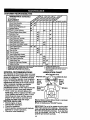
CUSTOMER RESPONSIBILITIES
You
FILL IN DATES
_t,O_/_,_,_O"j_.
Check Operator Presence and
T
Veer_ck
Systems
I/
R
Check for Loose Fasteners
(l_
A
T
S_arPe_Rep'_eM°wor_ades
LubricatTon
charZ
V_7
_"
0 Check
eatte,y
Leve_
R
!_,
_esn B=te,y_ Termi_ds
Check Transaxle Cooling
!G
N
_
V'
Adjust Blade Belt(s) Tension
I_s
Adjust Motion Drive Belt(s) Tension
_s
Check
EnC.e
o, L_v_
change
E,_ OH
E
N
_
V'
_
Filter
CleanAir Screen
V'
_V':
InspectMuffler/Spark
Arrester
t,/
Clesn Engine Cooling
Repl=,
o,Fi,.(,.qui_,_
!_,_,,
Replace Spark Plug
I_'
Replace Air Filter Paper Cartridge
V'=
Replace Fusl Filter
1 - Change more oltb'_ when operatic;
i Jl_
ll_
under _ heavy load _- In high _
i_._,
2 - S_;ce mo_ _ten when op_
in dkty o_du=tyconditions.
3 - ]1equ_
with o_ flte_, change og _er/50 bo_rs.
S - Jf equipped wNh ad_dtable
sy_
6 - Not requiredI _oped
wl_ _me
battery.
7 - TightenIm_ttmobplv_ bolt Io _5 It..Ibs.m_m.
4 - Relfar,e b_d_ mot=Dire.wh_mmowing
b uno_ _oa,
DOr_ ove_0hte_
GENERAL RECOMMENDATIONS
LUBRICATION CHART
The warranty on this tractor does not cover
o'rie Rod Ball Joints
items that have been subjected to operator eSpindle Zerk---- L
abuse or negligence. To receive full value
from the warranty, operator must maintain
eFront------H_l:ll
_Ft"" eFront
tractor as instructed in this manual. Some
Wheel
_.L__
_'__'." Wheel
adjustments will need to be made periodiBearing
L
Bearing
cally to properly maintain your tractor.
All adjustments in the Service and
eSteedng._
_"_
Adjustments section of this manual should
_
_-_eSpindle eEngine
Zerk
Sector
t
be checked at least once each season.
• Once a year you should replace the
spark plug, clean or replace air filter, and
check blades and belts for wear. A new
spark plug and clean air filter assure
Gear Teeth i
"_._ _:
proper air-fuel mixture and help your
engine run better and last longer.
OSpray Silicone lubdant (Move Boots to Lubricate)
BEFORE EACH USE
eGeneralPurpose
Grease
• Check engine oil level.
Check brake operation.
• Check tire pressure.
• Check operator presence and interlock
systems for proper operation,
@Refer to Maintenance "ENGINE" Section
• Check-fo_" loose fasteners,
IMPORTANT: Do not oil or grease the pivot points
which have special nylon bearings. Viscous lubdcants will attract dust and dirt that will shorten the
life of the self-lubricatingbearings. If you feel they
must be Jubricated, use only a dry, powdered
graphite type lubricant sparingly.
19
TRACTOR
Alwaysobservesafetyruleswhen performingany maintenance.
BRAKEOPERATION
If tractorrequiresmorethansix (6) feet
stoppingdistanceat highspeed in highest
gear,thenbrakemustbe adjusted.(See
"3"0 ADJUST BRAKE" in the Service and
Adjustments section of this manual).
TIRES
• Maintain proper air pressure in all tires
(See =PRODUCT SPECIFICATIONS"
section of this manual).
• Keep tires free of gasoline, oil, or insect
control chemicals which can harm rubber.
• Avoid stumps, stones, deep ruts, sharp
objects and other hazards that may
cause tire damage.
NOTE: To seal tire punctures and prevent
flat tires due to slow leaks, tire sealant
may be purchaeed from your local parts
dealer. Tire sealant also prevents tire dry
rot and corrosion.
OPERATOR PRESENCE SYSTEM
Be sure operator presence and interlock
systems are working propedy. If your tractor does not function as described below,
repair the problem immediately.
• The engine should not start unless the
clutch/brake pedal is fully depressed
and attachment clutch control is in the
disengaged position.
• When the engine is running, any
attempt by the operator to leave the
seat without first setting the parking
brake should shut off the engine.
• When the engine is running and the
attachment clutch is engaged, any
attempt by the operator to leave the
seat should shut off the engine.
• The attachment clutch should never
operate°unless the operator is in the
seat.
BLADE CARE
For best results mower blades must be
kept sharp. Replace bent or damaged
blades.
• Reassemble hex bolt, lock washer and
flat washer in exact order as shown.
• Tighten bolt securely (27-35 Ft. Lbs.
torque).
IMPORTANT:
Blade bolt is Grade 8 heat
treated.
edge up
Center
Hole
Assembly
Hex Bolt
-Star
*A Grade 8 heat treated bolt can be
identified by six lines on the bolt head.
TO SHARPEN
BLADE
NOTE: We do not recommend sharpening
blade, but if you do, be sure the blade is
balanced.
Care should be taken to keep the blade
balanced. An unbalanced blade will cause
excessive vibration and eventual damage
to mower and engine.
• The blade can be sharpened with a file
or on a grinding wheel. Do not attempt
to sharpen while it is on the mower.
• To check blade balance, you will need a
5/8" diameter steel bolt, pin, or a cone
balancer. (When using a cone balancer,
follow the instructions supplied with balancer).
NOTE: Do not use a nail for balancing
blade. The lobes of the center hole may
appear to be centered, but are not.
• Slide blade onto an unthreaded portion
of the steel bolt or pin and hold the bolt
or pin parallel with the ground. If blade
is balanced, it should remain in a hodzontal position. If either end of the blade
moves downward, sharpen the heavy
end until the blade is balanced.
BATTERY
BLADE REMOVAL
Your tractor has a battery charging system
• Raise mower to highest position to allow
which is sufficient for normal use.
access to blades.
However, pedodic charging of the battery
• Remove hex bolt, lock washer and flat
with an automotive charger will extend its
washer secudng blade.
life.
• Install new or resharpened blade with
• Keep battery and terminals clean.
trailing edge up towards deck as shown.
• Keep battery bolts tight.
IMPORTANT: To ensure proper assembly,
• Keep small vent holes open.
center hole in blade must align with star
• Recharge at 6-10 amperes for I hour.
on mandrel assembly.
2O
NOTE:The originalequipmentbatteryon
yourtractoris maintenancefree. Do not
attemptto openor removecapsor covers.
Addingor checkinglevelof electrolyteis
not necessary,
TO CLEANBATTERYANDTERMINALS
Corrosionanddirt on the batteryandterminalscan causethe batteryto "leak"
SAE VISCO_rPf
GRADES
Change the oil after every 50 hours of
operation or at least once a year if the
tractor is not used for 50 hours in one
power.
• Remove terminal guard.
• Disconnect BLACK battery cable first
then RED battery cable and remove
battery from tractor.
• Rinse the battery with plain water and
dry.
• Clean terminals and battery cable ends
with wire brush until bright.
• Coat terminals with grease or petroleum
jelly,
• Reinstall battery (See "REPLACING
BATTERY" in the SERVICE AND
ADJUSTMENTS
section of this manual).
V-BELTS
Check V-belts for deterioration and wear
after 100 hours of operation and replace if
necessary. The belts are not adjustable.
Replace belts if they begin to slip from
wear.
TRANSAXLE
COOLING
,"
year.
Check the crankcase oil level before starting the engine and after each eight (8)
hours of operation. Tighten oil fill cap/dipstick securely each time you check the oil
level.
TO CHANGE
ENGINE
OIL
Determine temperature
range expected
before oil change. All oil must meetAPI
service classification
SF, SG, or SH.
• Be sure tractor is on level surface.
• Oil will drain more freely when warm.
• Catch oil in a suitable container.
• Remove oil fill cap/dipstick.
Be careful
not to allow dirt to enter the engine
when changing oil.
• Remove drain plug.
• After oil has drained completely, replace
oil drain plug and tighten securely.
• Refill engine with oil through oil fill dipstick tube. Pour slowly. Do not overfill.
For approximate capacity see "PRODUCT SPECIFICATIONS"
section of this
manual.
The transmission fan and cooling fins
should be kept clean to assure proper
cooling.
Do not attempt to clean fan or transmission while engine is running or while the
transmission is hot.
• Inspect cooling fan to be sure fan
blades are intact and clean.
• Use gauge on oil fill cap/dipstick for
checking level. Insert dipstick into the
tube and rest the oil fill cap on the tube.
Do not thread the cap onto the tube
when taking reading.
Keep oil at
"FULL" line on dipstick. Tighten cap
onto the tube securely when finished.
• Inspect cooling fins for dirt, grass clippings and other materials. To prevent
damage to seals, do not use compressed air or high pressure sprayer to
clean cooling fins.
TRANSAXLE
PUMP FLUID
Oil Drain
Air
Screen
The transaxle was sealed at the factory
and fluid maintenance is not required for
the life of the transaxle. Should the
Oil Fill
Cap/Dipstick
transaxle ever leak or require servicing,
contact your nearest authorized service
center/department.
ENGINE
CLEAN
AIR
SCREEN
Air screen must be kept free of dirt and
chaff to prevent engine damage from overheating. Clean with a wire brush or compressed air to remove dirt and stubbom
dried gum fibers.
LUBRICATION
Only use high quality deiergent oil rated
with API service classification SF, SG, or
SH_ Select the oil's SAE viscosity grade
according to your expected operating temperature.
21
CLEANAIR INTAKE/COOLING
AREAS
Toinsurepropercooling,makesurethe
grassscreen,coolingfins, and other
proper position around stud. Replace if
necessary.
• Reassemble air cleaner, cartridge plate,
and nut.
• Reinstall air cleaner cover and secure
by tightening knob.
ENGINE OIL RLTER
external surfaces of the engine are kept
clean at all times.
Every 100 hours of operation (more often
under extremely dusty, dirty conditions),
remove the blower housing and other
cooling shrouds. Clean the cooling fins
and extemal surfaces as necessary. Make
sure the cooling shrouds are reinstalled.
Replace the engine oil filter every season
or with every second oil change if the tractor is used more than 100 hours in one
year.
MUFFLER
NOTE:
Operating the engine with a
blocked grass screen, dirty or plugged
cooling fins, and/or cooling shrouds removed will cause engine damage due to
overheating.
Inspect and replace corroded muffler and
spark arraster (if equipped) as it could create a fire hazard and/or damage.
SPARK PLUGS
Replace spark plugs at the beginning of
each mowing season or after every 100
hours of operation, whichever occurs first.
Spark plug type and gap setting are
shown in "PRODUCT SPECIFICATIONS"
section of this manual.
IN-LINE FUEL FILTER
The fuel filter should be replaced once
each season. If fuel filter becomes
clogged, obstructingfuel flow to carburetor, replacement is required.
• With engine cool, remove filter and plug
fuel line sections.
• Place new fuel filter in position in fuel
line with arrow pointing towards carburetor.
• Be sure there are no fuel line leaks and
clamps are propedy positioned.
• Immediately wipe up any spilled gasoline.
AIR FILTER
Your engine will not run properly using a
dirty air filter. Clean the foam pre-cleaner
after every 25 hours of operation or every
season. Service paper cartridge every
100 hours of operation or every season,
whichever occurs first.
Service air cleaner more often under dusty
conditions.
• Loosen knob and remove cover.
TO SERVICE PRE-CLEANER
• Slide foam pre-cleaner off cartridge.
• Wash it in liquid detergent and water.
• Squeeze it dry in a clean cloth. Allow it
to dry.
• Saturate it in engine oil. Wrap it in
clean, absorbent cloth and squeeze to
remove excess oil.
TO SERVICE CARTRIDGE
• Replace a dirty, bent, or damaged cartridge.
Foam
Cartridge
CLEANING
Rubber
Seal
oflean
all foreign
engine,matter.
battery, seat, finish, etc.
Keep finished surfaces and wheels free
of all gasoline, oil, etc.
• Protect painted surfaces with automotive type wax.
We do not recommend using a garden
hose to clean your tractor unless the electrical system, muffler, air filter and carburetor are covered to keep water out. Water
in engine can result in a shortened engine
life.
i
Knob
NOTE: Do not wash the paper cartridge
or use preasudzed air, as this will damage
the cartddge.
• Remove nut and cartridge plate.
• R_n_sta-II the pre-cleaner (cleaned and
oiled) over the paper cartridge.
• Check rubber seal for damage and
22
_CAUTION:
Before performing any service or adjustments:
• Depress clutch/brake pedal fully and set parking brake.
• Place motion control lever in neutral (N) position.
• Place attachment clutch in =DISENGAGED"
position.
i
Make
sure thekey
blades
moving key.
parts have completely stopped.
um ignition
=OFP and
andallremove
Disconnect spark plug wire from spark plug and place wire where it cannot come
in contact with plug,
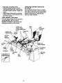
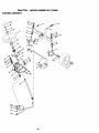
TRACTOR
• Remove two retainer springs from each
front link and remove links.
• Slide mower forward and remove belt
TO REMOVE MOWER
• Place attachment
•
•
•
•
clutch in "DISEN-
from electric clutch pulley.
• Slide mower out from under right side of
tractor.
IMPORTANT:
If an attachment other than
the mower deck is to be mounted on the
tractor, remove the front links.
GAGED" position.
Turn height adjustment knob to lowest
setting.
Lower mower to its lowest position.
Remove retainer spring holding antiswaybar to chassis bracket and disengage anti-swaybar from bracket.
Remove retainer springs from suspension arms at deck and disengage arms
from deck;
• Raise attachment
tion.
TO INSTALL MOWER
Follow procedure described in "INSTALL
MOWER AND DRIVE BELT" in the
Assembly section of this manual.
lift to its highest posi-
AdiusVnent
Lift
Nuts
Links
Suspension
Arms
Front Suspension
Bracket
Front Mower
Bracket
Electric Clutch
_
Chassis
Bracket
Front
Suspension
Bracket
Retainer
Springs
Retainer
Spring
Mower
Bracket
Anti-Sway
Bar
Retainer
Springs
23
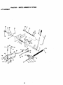
TO LEVEL MOWER
HOUSING
Adjust the mower while tractor is parked
on level ground or driveway. Make sure
tires are properly inflated (See "PRODUCT SPECIFICATIONS').
If tires are
over or underinflated, you will not properly
adjust your mower.
SIDE-TO-SIDE ADJUSTMENT
.. Raise mower to its highest position.
Measure height frombottom of deck
cud to ground level at front comers of
mower. Distance "A" on both sides of
mower should be the same.
If adjustment is necessary, make adjust_ment on one side of mower only.
To raise one side of mower, tighten lift
link adjustment nut on that side.
• To lower one side of mower, loosen lift
link adjustment nut on that side.
NOTE: Each full turn of adjustment nut
will change mower height about 3/16".
• Recheck measurements after adjusting.
Bottom
_ottom
_
--
• To raise front ot mower housing, loosen
nut =H" from trunnion on both front links.
Tighten nut =G" on both front links an
equal number of turns.
.
• When distance =F" is 118" to 1/2" lower
at front than rear, tighten nut UH"
against trunnion on both front links.
NOTE: Each full tum of nut =G" will
change dim. "F" by approximately 3/8".
• Recheck side-to-side adjustment.
Mandrel
Both Front Links Should be Equal in Length
of Cud
Groun
FRONT-TO-BACK ADJUSTMENT
IMPORTANT: Deck must be level side-toside. If the following front-to-back adjustment is necessary, be sure to adjust both
front links equally so mower will stay level
side-to-side.
To obtain the best cutting results, the
mower housing]should be adjusted so the
front is approx,mately 1/8" to 1/2' lower
than the rear when the mower is in its
highest position.
Check adjustment on d!_htside of tractor.
Measure d,stance "F" dtrectly in front of
and behind the mandrel at bottom edge of
mower housing as shown.
• Before making any necessary adjustments, check that both front links are
equal in length.
• If links are not equal in length, adjust
one link to same length as other link.
• To lower front of mower housing, loosen
nut =G" on both front links an equal
number of turns.
• When distance =F" is 1/8" to 1/2" lower
at front than rear, tightennut "H" against
trunnion on both front links.
Trunnion f
Front
Links_
_'
TO REPLACE
MOWER
DRIVE
BELT
MOWER DRIVE BELT REMOVAL
• Park tractor on a level surface. Engage
parking brake.
• Remove screws from left hand mandrel
cover and remove cover.
• Roll belt over the top of left hand mandrel pulley.
• Remove belt from electdc clutch pulley.
• Remove belt from idler pulleys.
• Remove any dirt or grass clippings
which may have accumulated around
mandrels and entire upper deck surface.
• Check primary idler arm and two idlers
to see that they rotate freely.
• Be sure spdng is securely hooked to pdmary idler arm and bolt in mower housing.
24
• Roll belt into upper groove of left hand
mandrel pulley.
• Carefully check belt routing making sure
belt is in the grooves correctly and
inside bolt keepers.
• Reassemble left hand mandrel cover.
MOWER DRIVE BELT INSTALLATION
• Install belt in both idlers. Make sure belt
is in both belt keepers at the idlers as
shown.
• Install new bolt onto electric clutch pulley.
Screws
Left Hand
Idler
Spdng
Pulleys
Cover
Electdc
Clutch
Primary
Idler Arm
Bolt in
Mower
Housing
Left I.
Mandrel
Mower
Drive Belt
Belt
Keepers
TO REPLACE MOWER BLADE DRIVE
BELT
Park the tractor on level surface. Engage
parking brake.
• Remove mower ddve belt (See =TO
REPLACE MOWER DRIVE BELT" in
this section of this manual).
• Remove mower (See =TO REMOVE
MOWER" in this section of this manual).
• Remove screws from right hand mandrel cover and remove cover. Unhook
spring from bolt on mower housing.
• Carefully roll belt off right hand mandrel
pulley.
• Remove belt from center mandrel pulley, idler pulley, and left hand mandrel
pulley.
• Remove any dirt or grass which may
.
have _Lccumulated around mandrels ana
entire upper deck surface.
• Check secondary idler arm and idler to
see that they rotate freely.
idler arm and sway bar bracket.
Install new belt in lower groove of left
hand mandrel pulley, idler pulley, and
center mandrel pulley as shown.
_BeRollsure
is h,.o_h
kedin
secondary
belt spring
over right
hand
mandrel
pulley.
Make sure belt is in all grooves properly.
Reconnect spring to bolt in mower
.
housing and reinstall dght hana manare
cover.
• Reinstall mower to tractor (See
=INSTALL MOWER AND DRIVE BELT"
in the Assembly section of this manual)=.
• Reassemble mower drive bolt (See "TO
REPLACE MOWER DRIVE BELT" in
this section of this manual).
25
LeftHand
Mandrel
Mower Blade
Ddve Belt
Center
Mandrel
Right Hand
Cover
Screw
Idler
Arm
Spdng
Anit-Sway Bar
Bracket
TO ADJUST
ATTACHMENT
Idler
Pulley
CLUTCH
.,
The electric clutch should provide years of
service. The clutch has a built-in brake
that stops the pulley within 5 seconds.
Eventually, the intemal brake will wear
which may cause the mower blades to not
engage, or, to not stop as required.
Adjustments should be made by your
nearest authonzed service center/department.
• Make sure attachment clutch and ignition switches are in =OFF" position.
• Adjust the three nylon Iocknuts until
space between clutch plate and rotor
measures .012" at all three slot locations cut in the side of brake plate.
Rotor.,_,.
Road test tractor for proper stopping
distance as stated above. Readjust if
necessary. If stopping distance is still
greater than six (6) feet in highest gear,
further maintenance is necessary.
Contact your nearest authorizedservice center/department.
With Parking Brake "Engaged"
Nut "A"
Jam Nut
3peraSng
Arm
ClutchtPlat_e
./I/\
Nylon Locknut (3F
TO REPLACE MOTION DRIVE BELT
Park the tractor on level surface. Engage
parkingbrake. For ease of service there
is a belt installation guide decal on bottom
of left footrest.
• Remove mower (See "TO REMOVE
MOWER" in this section of this manual.)
Brake Plate
NOTE: After installing a new electdc
clutch, m9 tractor at full throttle and
engage and disengage electric clutch 10
cycles to wear in clutch plate._
TO ADJUST
BRAKE
Your tractor is equipped with an adjustable
brake system which is mounted on the
side of the transaxle.
If tractor requires more than six (6) feet
stopping distance at high speed in highest gear, then brake must be adjusted.
• Depress clutch/brake pedal and engage
parking brake.
• Measure distance between brake operating arm and nut "A" on brake rod.
• If distance is other than 1-1/2", loosen
jam-nut and tum nut =A" until distance
becomes 1-1/2". Retighten jam nut
: against nut =A".
BELT REMOVAL • Engage parking brake (creates slack in
belt).
• Remove belt from clutching and fan
idler pulleys.
• Loosen belt keeper above transaxle pulley.
• Remove belt from transaxle pulley.
• Remove belt from engine pulley and
front V-idler pulley.
• Pull belt out of all belt keepers and
remove from tractor.
26
BELTINSTALLATION
-
NOTE: If for any reason the effort to
move the motion control lever becomes
too excessive, reverse the above adjustment procedure by loosening Iocknut 1/4
turn.
Road test tractor after adjustment and
repeat procedure if necessary.
TRANSMISSION
REMOVAL/REPLACEMENT
• Place V part of belt intogrooves on
engine pulley and front V-idler, making
sure to route belt inside of all belt keep-_
ers,
• Route belt on right side, coming from Vidler, towards back of tractor, above
midspan belt keeper and to top of
transaxle pulley.
• Route belt on left side, coming from
engine pulley, towards back of tractor
and through loop in midspan bolt keeper.
• Place V part of belt into grooves on
transaxle and fan idler pulleys, making
sure to route belt inside of all belt keepers.
• Retighten belt keeper above transaxle
pulley.
• Place belt around clutching idlers as
shown, making sure to route belt inside
of all belt keepers.
• Chock to be sure belt is positioned corroctly and is on proper side o1all belt
keepers.
• Reinstall mower.
IMPORTANT:
Check brake adjustment.
Tractor VoBelt Drive Schematic
Viewed from L.H. Side of Tractor
•
Belt
Transaxle
Clutching Idler Keeper
Engine Clutching Fiat Idler_
Pulley
Above Belt
V-Idler
Belt Keepers
I_
J
Jam Nut
_
TO ADJUST
MENT
As Viewed from Bottom
MOTION
CONTROL
WHEEL
ALIGN-
Front wheel toe-in is required for proper
steedng operation. Toe-in was set at the
factory and adjustment should not be necessary. If parts in the front axle or steedng
mechanism have been replaced or damaged, check toe-in and adjust if necessary.
TO CHECK TOE-IN
V-Idler
TO ADJUST
STEERING
Locknut
If steeringwheel
crossbars are not hodzontal (left to right) when wheels are positioned straight forward, remove steenn_l
wheel and reassemble per instructions in
the Assembly section of this manual.
FRONT WHEEL TOE-IN ADJUSTMENT
Belt
Fan
KeeperEnIdler
ine
_
Should your transmission require removal
for service or replacement, it should be
purged after reinstallation and before operating the tractor. See =PURGE TRANSMISSION" in the Operation section of this
manual.
• Position front wheels straight ahead.
• Measure distance between wheels at
front and rear of tires (dimensions =A"
and =B').
• Front dimension =A" should be 1/8" to
1/4" less than rear dimension "B".
LEVER
The motion control lever has been preset
at the factory and adjustment should not
be necessary.
If for any reason the motion control lever
will not hold its position while at a selected
speed, it may be adjusted at the friction
pack located on the right side of chassis.
• Park tractor on level surface. Stop tractor by tuming ignition key to "OFF'position and engage parking brake.
• Place motion control lever in neutral (N)
position.
TO ADJUST
TOE-IN
• Loosen jam nuts at adjustment sleeves
on tie rod.
• Adjust tie rod until dimension "A" is 1/8"
to 1/4" less than dimension =13".
• Tighten jam nuts securely.
FRONT WHEEL CAMBER
The front wheel camber is not adjustable
on your tractor. If damage has occurred to
affect the front wheel camber, contact your
nearest authorized service center/dopartment.
Tighten
IocknutIocknut,
1/4 turn.
While holding
loosen jam nut
While holding Iocknut, tighten jam nut
securely.
27
The other vehical must also be a 12 volt
negative grounded system. Do not use
your tractor battery to start other vehicles.
TO ATTACH JUMPER CABLES • Connect each end of the RED cable to
the POSITIVE (+) terminal of each battery, taking care not to short against
chassis.
• Connect one end of the BLACK cable to
the NEGATIVE (-) terminal of fully
charged battery.
• Connect the other end of the BLACK
cable to good CHASSIS GROUND,
away from fuel tank and battery.
TO REMOVE CABLES, REVERSE
ORDER • BLACK cable first from chassis and
then from the fully charged battery.
• RED cable last from both batteries.
Sleeves
Jam Nuts
TO REMOVE
WHEEL
FOR REPAIRS
FRONT WHEEL
• Block up axle securely.
• Remove axle cover, retaining ring and
washers to allow wheel removal.
Repair tire and reassemble.
Replace washers and snap retaining
nng securely in axle groove.
• Replace axle cover.
REAR WHEEL -
"Positive"(+)
L.H. Panel
Block rear axle securely.
Remove five (5) hub bolts to allow
wheel removal.
• Repair tire and reassemble. Replace
and t=ghtenhub bolts securely.
=Negative" (-)
I-_611
Bolt _
NOTE: To seal tire punctures and prevent
flat tiros due to slow leaks, bre sealant
may be purchased from your local parts
dealer. Tire sealant also prevents tire dry
rot and corrosion.
REPLACING
BATFERY
ACAUTION:
Do not short battery terminals by allowing a wrench or any other
object to contact both terminals at the
same time. Before connecting battery,
remove metal bracelets, wristwatch
bands,rings,etc.
Positive terminal must be connected first
to prevent sparking from accidental
grounding.
• Lift hood to raised position.
• Remove terminal guard.
• Disconnect BLACK battery cable then
RED battery cable and carefully remove
battery from tractor.
• Install new battery with terminals in
same position as old battery.
• Reinstall terminal guard.
• First connect RED battery cable to pealfive (+) battery terminal with hex bolt,
keps nut as shown. Tighten securely.
• Connect BLACK grounding cable to
negative (-) battery terminal with
remaining hex bolt, keps nut. Tighten
securely.
Close terminal access doors.
Washers
Rs n,ng
Ring
TO START ENGINE WITH A WEAK
BATTERY
_,CAUTION:
Lead-acid batteries generate explosive gases. Keep sparks, flame
and smoking materials away from batteries. Always wear eye protection when
around batteries.
If your battery is too weak to start the
_ngine, it should be recharged. (See
'BATrERY" in the MAINTENANCE sec:ion of this manual).
f "jumper cables" are used for emergency
;tatting;,follow this procedure:
MPORTANT: Your tractor Is equipped
_ith a 12 volt negative grounded system.
Close hoo.d.
28
Keps Nut _
Terminal
.....
A=e
_
_-
....
_
u...,
Bolt
TO REMOVE HOOD AND GRILL
ASSEMBLY
• Raise hood.
.. ' '°^
Door..___."-"" :.--"_Positive
.- _
Terrain=_'_-/-_...
= _""_
Guard /
_'f_L-.J//
(Red) Cable
Negative(Black)
Cable
• Unsnap headlight wire connector.
Stand
front of tractor.
Grasp
hood
sides, in
tilttoward
engine and
liftoff
of at
tractor.
• To replace, reverse above procedure.
TO REPLACE HEADLIGHT
BULB
• Raise hood.
• Pull bulb holder out of the hole in the
backside of the gdll.
• Replace bulb inholder and push bulb
holder securely back into the hole in the
backside of the grill.
• Close hood.
INTERLOCKS
AND RELAYS
Loose or damaged wiring may cause your
tractor to run poorly, stop running, or prevent it from starting.
• Check wiring. See electrical wiring diagram in the Repair Parts section.
Headlight
ENGINE
Maintenance, repair, or replacement of the
emission control devices and systems,
which are being done at the customers
expense, may be performed by any nonroad engine repair establishment or individual. Warranty repairs must be performed by an authorized engine manufacturer's service outlet.
TO ADJUST THROTTLE
CONTROL
CABLE
TO REPLACE FUSE
Replace with 30 amp automotive-type
plug-in fuse. The fuse holder is located
behind the dash.
TO ADJUST ATTACHMENT
LIFT
SPRING
The throttle control has been preset at the
factory and adjustment should not be necessary. Check adjustment as described
below before loosening cable. If adjustment is necessary, proceed as follows:
• While holding spring bushing with
wrench, loosen jam nut.
• Turn adjustment bolt clockwise to
extend spring and reduce lift effort for
heavier attachments.
•Tum adjustment bolt counterclockwise
for lighter attachments.
• Retighten jam nut against spdng bushing.
IMPORTANT: Do not adjust for maximum
spdng tension when using light attachments such as a mower. Adjust lift lever
springto aid in liftingattachment. Do not
overpower spring. When removing attachment, always adjust spring]ension to its
lowest position.
control
lever not
to fast
position.
With engine
running,
move throttle
Check that speed control lever is
against stop screw. If it is not, loosen
casing clamp screw and pull throttle
cable untillever is against screw.
Tighten clamp screw securely.
Idle Fuel Adjusting
Idle Speed
I Screw
Throttle
.
Cable
AdjU__Bushing
_Attachment
_Lift
Spdng
Choke
, Control
Cable
!(//" - / JamNut
Stop
Screw
Clamp Screw
29
PRELIMINARY
TO ADJUST CHOKE CONTROL
The choke control has been preset at the
factory and adjustment should not be necessary, check adjustment as described
below before loosening cable. If adjustment is necessary, proceed as follows:
• With engine not running, move choke
control (located on dash panel) to full
choke position.
• Remove air cleaner cover, filter and cartridge plate to expose carburetor choke
(See "AIR FILTER" in the Customer Responsibilitiessection of this manual).
• Choke should be closed. If it is not,
loosen casing clamp screw and move
choke cable until choke is completely
closed. Tighten casing clamp screw securely.
• Reassemble air cleaner.
SE'I-FfNG -
• Be sure you have a clean air filter, and
the throttle control cable is adjusted
properly (see "TO ADJUST THROTTLE
CONTROL CABLE" in the Service and
Adjustments section of this manual).
• With engine off turn idle fuel adjusting
needle in (clockwise) closing it finger
tight and then turn out (counterclockwise) 1 turn.
FINAL SETTING • Start engine and allow to warm for five
minutes. Make final adjustments with
engine running and shift/motion control
lever in neutral (N) position.
• The high idle is set at the factory and
cannot be adjusted.
• Idle sDeed settina - With throttle control
lever in slow position, engine should
idle at 1200 RPM. If engine idles too
slow or fast, turn idle speed adjusting
screw in or out until correct idle is
attained.
Closed for
Choke
• Idle fuel needle settina - With throttle
control lever in slow position, tum idle
fuel adjusting needle in (clockwise) until
engine speed decreases and then turn
out (counterclockwise) approximately
3/4 turn to obtain the best low speed
performance.
• Recheck idle speed. Readjust if necessary.
TO ADJUST CARBURETOR
The carburetor has been present at the
factory and adjustment should not be necessary. However, minor adjustment may
be requiredto compensate for differences
in fuel, temperature, altitude or load. If the
carburetor does need adjustment, proceed
as follows:
In general, turning the adjusting needles
in (clockwise) decreases the supply of fuel
to the engine giving a leaner fuel/air mixture. Turning the adjusting needles out
(counterclockwise) increases the supply of
fuel to the engine giving a richer fuel/air
mixture.
IMPORTANT: Damage to the needles
and the seats in carburetor may result if
screw is turned in too tight.
ACCELERATION
TEST -
• Move throttle control lever from slow to
fast position. If engine hesitates or dies,
tum idle fuel adjusting needle out
(counterclockwise) 1/8 tum. Repeat test
and continue to adjust, if necessary,
until engine accelerates smoothly.
High speed stop is factory adjusted. Do
not adjust-damage may result.
IMPORTANT: Never tamperwith the
engine govemor, which is factory set for
proper engine speed. Overspeeding the
engine above the factory high speed setting can be dangerous. If you think the
engine-govemed high speed needs
adjusting, contact your nearest authorized
service center/department, which has
proper equipment and experience to make
any necessary adjustments.
3O
Immediately prepare your tractor for storage at the end of the season or if the tractor will not be used for 30 days or more.
_,CAUTION:
Never store the tractor with
gasoline in the tank inside a building
where fumes may reach an open flame or
spark. Allow the engine to cool before storing in any enclosure.
TRACTOR
Remove mower from tractor for winter
storage. This will allow you to clean it thoroughly. Remove all did, grease, leaves,
etc. Store in a clean, dry area.
• Clean entire tractor (See =CLEANING"
in the Maintenance section of this manual).
• Inspect and replace belts, if necessary
(See belt replacement instructions in the
Service and Adjustments section of this
manual).
• Lubricate as shown in the Maintenance
section of this manual.
• Be sure that all nuts, bolts and screws
are securely fastened. Inspect moving
parts for damage, breakage and wear.
Replace if necessary.
• Touch up all rusted or chipped paint surfaces; sand lightly before painting.
BATTERY
• Fully charge the battery for storage.
• After a period of time in storage, battery
may require recharging.
• To help prevent corrosion and power
leakage dudng long pedods of storage,
battery cables should be disconnected
and battery cleaned thoroughly (see
"TO CLEAN BA'I-I'ERY AND TERMINALS" in the Maintenance section of
this _nanual).
• After cleaning, leave cables disconnected and place cables where they cannot
come in contact with battery terminals.
• If battery is removed from tractor for
storage, do not store battery directly on
concrete or damp surfaces.
Also, experience indicates that alcohol
blended fuels (called gasohol or using
ethanol or methanol) can attract moisture
which leads to separation and formation of
acids during storage. Acidic gas can damage the fuel system of an engine while in
storage.
• Drain the fuel tank.
• Start the engine and let it run untilthe
fuel lines and carburetor are empty.
• Never use engine or carburetor cleaner
products in the fuel tank or permanent
damage may occur.
• Use fresh fuel next season.
NOTE: Fuel stabilizer is an acceptable
altemative in minimizing the formation of
fuel gum deposits dudng storage. Add stabilizer to gasoline in fuel tank or storage
container. Always follow the mix ratio
found on stabilizer container. Run engine
at least 10 minutes after adding stabilizer
to allow the stabilizer to reach the carburetor. Do not drain the gas tank and carburetor if using fuel stabilizer.
ENGINE
OIL
Drain oil (with engine warm) and replace
with clean engine oil. (See =ENGINE" in
the Maintenance section of this manual).
CYLINDER(S)
• Remove spark plug(s).
• Pour one ounce of oil through spark plug
hole(s) into cylinder(s).
•Tum
ignition key to "START" position for
a few seconds to distribute oil
• Replace with new spark plug(s).
OTHER
• Do not store gasoline from one season
to another.
• Replace your gasoline can if it starts to
rust. Rust and/or dirt in your gasoline will
cause problems.
• If possible, store your tractor indoors
and cover it to give protection from dust
and dirL
• Cover your tractor with a suitable protective cover that does not retain moisture.
Do not use plastic. Plastic cannot
breathe, which allows condensation to
form and cause your tractor to rust.
IMPORTANT: Never cover tractor while
engine and exhaust areas are still warm.
ENGINE
FUEL SYSTEM
IMPORTANT:
It is important to prevent
gum deposits from forming in essential
fuel system parts such as carburetor, fuel
filter, fuel hose, or tank dudng storage.
31
TROUBLI=SHOOTING
PROBLEM
CHART
CORRECTION
CAUSE
Will not start
• Out of fuel.
• Engine not =CHOKED" prop-
erly.
• RII fuel tank.
• See =TO START ENGINE" in
• Engine flooded.
Operation section.
• Wait ssveml minutes before
•
•
•
•
•
•
•
•
Bad spark plug.
Dirty air filter.
Dirty fuel filter.
Water in fuel.
• Loose or damaged wiring.
• Carburetor out of adjustment.
• Engine valves out of adjustment.
attempting to start.
Replace spark plug.
Clean/replace air filter.
Replace fuel tilter.
Drain fuel tank and carburetor,
refill tank with fresh
gasoline and mplaca fuel filter.
• Check all wiring.
, See =ToAdjust Carburetor" in
Service and Adjustments
section.
Contact an authorized service
center.
i
Hard to start
•
•
•
•
•
Dirtyair filter.
Bad spark plug.
Weak or dead battery.
Dirtyfuel filter.
Stale or dirty fuel.
• Loose or damaged wldng.
• Carburetor out of adjustment.
• Engine valves out of adjustment.
Engine will not rum
over
Engine clicks but will
:lot start
• Clutchrbrake pedal not
depressed.
• Attachment dutch is engaged.
• Weak or dead battery.
• Blown fuse.
• Corroded battery ten.rials
• Loose or damaged wldng.
• Faulty ignitionswitch.
• Faulty solenoid or starter.
• Clean/raplace air filter.
• Replace spark plug.
_• Recharge or replace battery.
Replace fuel filter.
Drain fuel tank and refill with
fresh gasoline.
• Check all widng.
• See =ToAdjust Carburetor" in
Service and Adjustments
section.
Contact an authorized service
center,
Depress clutch/orake pedal.
• Faulty operator presence
switch(es).
Disengage attachment clutch.
Recharge or replace battery.
Replace fuse.
Clean battery terminals.
Check all widng.
Check/replace ignitionswitch.
Chack/raplace solenoid or
starter
Contact an authorized service
center.
• Weak or dead battery.
• Corroded battery terminals.
Recharge or replace battery.
Clean battery terminals.
• Loose or damaged widng.
• Faulty solenoid or starter.
32
•
*
•
•
•
•
Check all wiring.
Check/replace
solenoid or
•
starter.
TROUBLESHOOTING CHART
CAUSE
PROBLEM
• Cutting too much grass/too
Lossofpower
fast.
• Thm_e in "CHOKE" position.
• Build-up of grass, leaves and
trash under mower.
• Dirty air filter.
• Low oil level/dirty oil.
• Faulty spark plug.
• Dirty fuel filter.
• Stale or dirty fuel.
• Water in fuel.
• Spark plug wire loose.
Dirty engine air screen/fins.
Dirty/clogged muffler.
Loose or damaged widng.
Carburetor out of adjustment.
Engine valves out of adjustment.
Excessive vibration
Wom, bent or loose blade.
Bent blade mandrel.
Loose/damaged part(s).
i Engine continues to
run when operator
leaves seat with at
tachment clutch
ing.
Clean/replace air filter.
Check ell level/change oil.
Clean and regap or change
spark plug.
Replace fuel filter.
Drain fuel tank and refill with
fresh gasoline.
Drain fuel tank and carburetor,
refill tank with fresh gasoline and
replace fuel filter.
Connect and tighten spark plug
wire.
• Clean engine air screen/fins.
Claanireplace muffler.
• Check all widng.
• See "To Adjust Carburetor" in
Service and Adjustments
section.
; • Contact an authodznd service
center.
• Replace blade. Tighten blade
polL
• Replace blade mandrel.
• Tighten loose part(s). Replace
damaged parts.
• Check wiring, switches and connections. If not
corrected, contact an authorized
service center/
department.
Wom, bent or loose blade.
• Replace blade. Tighten blade
bolt.
• Level mower deck.
• Clean underside of mower hous-
Mover deck not level.
Buildup of grass, leaves, and
trash under mower.
Bent blade mandrel.
Clogged mower deck vent
holes from buildupof
grass, leaves, and trash
around mandrels.
Mower blades will not
rotate
tiordreduce speed.
Adjust thmtfie control.
Clean underside of mower hous-
Faulty operator-safety presence control system.
engaged
Poor cut - Uneven
CORRECTION
• Set in =Higher Cut" posi-
Obstruction in clutch mechanism.
Wom/damaged mower ddve
belt.
33
ing.
• Replace blade mandrel.
• Clean around mandrels to open
vent holes.
• Remove obstruction.
• Replace mower drive belt.
TROUBLESHOOTING
PROBLEM
CHART
CAUSE
CORRECTION
rotate (cont'd)
• Frozen idler pulley.
• Frozen blade mandrel.
• Replace idler pulley.
• Replace blade mandrel.
Poor grass discharge
• Engine speed too slow.
• Place throttle control in =FAST"
Mower blades will not
• Travel speed too fast.
• Wet grass.
• Mower deck not level.
• Low/uneven tire air pressure.
• Worn, bent or loose blade.
• Buildup of grass, leaves and
trash under mower.
• Mower ddve belt worn.
• Blades impropedy installed.
• Improper blades used.
=• Clogged mower deck vent
holes from buildup of
grass, leaves, and trash
around mandrels.
position.
• Shift to slower speed.
• Allow grass to dry before mowing.
• Level mower deck.
• Check Ures for proper air pressure.
• Replace/sharpen blade. Tighten
blade bolt.
• Clean underside of mower
housing.
• Replace mower ddve bell
• Reinstall blades sharp edge
down.
• Replace with blades listed in
this manual.
• Clean around mandrels to open
vent holes.
Heso_Ight(s)not work
ing (if so equipped)
• Switch is "OFF'.
•Tum
•
•
•
•
•
•
•
•
Bs_erywill not charge
• Bad battery cell(s).
• Poor cable connections.
• Faulty regulator (if so
equipped).
• Faulty alternator.
• Replace battery.
• Check/clean all connections.
• Replace regulator.
• Freewheel control in "disen-
• Place freewheel control in
gaged" position.
• Motion ddve belt wom, damaged-or broken.
• Air trapped in transmission
dudng shipment
or servicing.
=engaged" position.
• Replace motion ddve belt.
• Engine throttle control not set
at "SLOW" position for 30 seconds before stopping engine.
• Move throttle control to =SLOW"
Loss of drive
Engine =backfires"
when tuming engine
"OFF"
Bulb(s) burned out.
Faulty light switch.
Loose or damaged widng.
Blown fuse.
34
switch "ON'.
Replace bulb(s).
Checldreplace light switch.
Check wiring and connections.
Replace fuse.
• RePlace aifemator.
• Purge transmission.
position and allow to idle for 30
seconds before stopping
engine.
TRACTOR . . MODEL NUMBER
917.273060
SCHEMATIC
OPERATO_
PRESENG_
RELAY
RELAy
IGNmON ftwrrcH
L STAnT I.÷S÷All
_E_)
R_J_IOyA_._
CONNECTIONS
GFG
NON.R¢_MOVABLE
B
E NG INE CONNECTOR
_TOR--_
---I_at
DA
TRACTOR
NOTE: {F W(R(NG|NSUILATED GARBURET(}R
CONNECTOR
(REO W1RE)
OULD _ REPLACEDTO
PROPERLYSECURE YOUR
(Ye.LOW_RS__.U_
_R_NG,
TO LIGHT PKG,)
35
T;_V
W_R_
TRACTOR
- - MODEL
NUMBER
917.273060
ELECTRICAL
22
33
11
12
iI
26
i
I
I
36
TRACTOR
- - MODEL
NUMBER
917.273060
ELECTRICAL
KEY
PART
NO.
NO.
1
2
8
10
11
12
16
19
20
21
22
24
25
26
27
28
29
30
33
40
41
42
43
45
50
52
81
83
144927
74760412
7603J
145211
150109
145769
153664
STD551125
73350400
161785
4152J
4014,.I
146686
108824X
73510400
157899
160784
163S68
140403
164069
17720408
131563
145673
122822X
154963
141940
109748X
163996
DESCRIPTION
Battery
Bait Hex Head 114-20x 3/4
Tray, Battery
Bolt114-20 x 7.5 Zinc
Hold down Battery
Dash Mount
Nut Push Nylon 1/4"
Switch Intedock Push-In
Washer, Lock 1/4
Nut, Jam Hex 114-20
Hamess Socket LightW/4152J
Bulb Light
Cable, Battery
Cable, Battery
Fuse
Nut Keps He)( 1/4-20 Unc
Cable, Ground
Switch, Plunger
Switch, Ign
Key, Ignition
Hameas Ign.
Screw 1/4-20 x 1/2
Cover, Terminal
Solenoid
Ammeter
Sw_tch,PTO
ProtectionWire Loop
Relay Asm.
BulbholderAsm IncandescentSV
NOTE: All componentd_menslonsgiven in U.S. inches
1 inch = 25.4 mm
37
TRACTOR
- - MODEL
NUMBER
917.273060
CHASSIS AND ENCLOSURES
37
122
17
52
17
56
! 17
19
100
68
2
102
86
17
TRACTOR
- - MODEL
NUMBER
917.273060
CHASSIS AND ENCLOSURES
KEY
PART
NO.
NO.
1 150253
2 140506
4 73800700
5 163976
6 157882
7 17720408
8 145166
14 161023X558
15 160568
16 121794X
17 17490612
18
160564X558
19
19131312
20 STD523710
21 73680600
23
17490616
24
145243X558
28
145244X558
30
145052
31 161419
32 161327
33 161326
34
142131
35 19111116
36 STD522507
37
163982X558
39
136961
40
156111
42
STD533710
43
136939
44
136940
45
154913
47
1749G608
KEY
DESCRIPTION
Rail, Frame RH
Dmwbar, Gt
Nut, LockHex 7/16Unc
DashYTGT2Cyl
Dash, Lower Vgt One Piece
Screw, ThdCut 1/4-20xl/2
Support, Buttery
HoodAsm.,PntY'l"GT
LensAsrn Headlight Bur
Cover, Access
Screw, Thdrol 3/6-16 x 3/4
Gdlle
Washer 13/32x 13/16x 12 Ga.
Bolt, Fin Hex 3/8-16 x 1
NutCrownlock 3/8-16Unc
ScmwThdro| 3/8-16xl"ry-'Tt
Footrest,RH
Footrest,LH
Saddle, Hydro
Brace, Supt 1-pc VGT Steedn9
Bracket, Pivot Chassis Lh
Bmcket, Pivot Chassis Rh
Bracket, Engine Support Rear
Washer 11/32 x 11/16 x 16 Ga.
Bolt, Fin Hex 5/16-18 x 3/4
Fender Pnt
Bracket,AxleFront
Bracket, SupportAxle/Engine
Bolt, Carriage 3/6-16xl
Bracket,Spnsn Front Lh
Bracket, Spnsn Front Rh
BracketAsm., Susp Chassis Rh
Screw ThdroL 3/8-16 x 1/2
PART
DESCRIPTION
NO.
NO.
Bracket,Chassis Front
50
152728
Nut, Crownlock 5/16-18 Unc
52
STD541431
BracketAsm., Susp Chassis Lh
56
154914
BracketAsm., Fender
58
137113
Screw ThdroL 3/6-16 x 1-1/4
60
17490620
Washer 13/32 x lx 14 Ga.
63
19131614
ScrewThdrol. 5/16-18x 1/2
68
17490508
Guide, Bolt Mid Span
70
137159
Stop,Over Center Mower
84
142992
Belt Fin Hex 7/16-14 UNC x 1
86 74760716
Washer, LockExt. Tooth 3/8
90 STD551237
Rail,
Frame I_h
91
156586
Push Nut, Nylon
95
105531X
BracketSkid Chassis
98
140503
Rod ByPass
99
140871
Cap By Pass Rod
100 124236X
Screw Thdrol 3/8-16 x 1-3/4
101 17490628
Retainer,Spring
102 STD624003
Lock, By Pass
103 142273
BoR5/16-18 Tr
106 138776
Washer 13/32 x I x 16 Ga,
120 19131616
Screw Hex Wshd 8-18 x 7/8
122 161464
Screw Hwhd Hi-Lo#13-16 x 3/4
130 164863
Cup Holder
138 163975X428
Bolt Shoulder5/16-18 1-1"
139 161330
Magnet Y'rGT
140 163806
StOkerPlate YTGT
141 163805
BracketDash Rh
142 161897
BracketDash Lh
144 161900
Fastener Nut Pal
147 162967
ExtrusionBumpers
148 164655
Duct Heat Hood
150 161237
NOTE: All componentdimensionsgiven in U.S. inches
1 inch= 25.4 mm
39
TRACTOR
- - MODEL
NUMBER
917.273060
GROUND DRIVE
42
15
47
I
9
7
104
61
112
IO0
2
4O
TRACTOR
- - MODEL NUMBER
917.273060
GROUND DRIVE
KEY
NO.
PART
NO.
2 7070E
3 7563R
5 STD541437
6 STD561210
7
140507
9
140080
15 STD551037
17 140921
20 73940800
22
156103
23
130564
28 STD541237
29 140494
30
19131616
33
12000053
34
124236X
35
137648
36
149412
37
121749X
38
150035
39 74321016
40
5304J
41
73661000
42 8883R
46
145170
47
138228
48
72110612
50
51
52
53
54
55
56
58
61
64
65
66
67
68
69
70
71
131494
STD541437
139123
207J
161590
106706X
140218
74760724
140488
154752
67609
140296
19181312
STD571812
123800X
164892X428
151179
KEY
NO.
DESCRIPTION
Key 1/4 x 2.5
Washer, Thrust,Axle
Nut, Crowniock 3/6-16
Pin, Cotter
Wheel, HubAssembly
Bolt, Hub
Wahser 13i32x13/16x16Ga.
Spdng
Nut Hex Jam Topiock1/2-20
AnnAsmSh_
Knob
Nut
Brake, Rod
Washer 13/32xl x 16 Ga.
Ring E
Cap, Plunger
Red, ParkingBrake
Spring, Drive Ground
Washer 25/32 x 1-1/4 x 16 Ga.
Nyliner
Screw, Fin. #10-24 x 1
Actuator,InterlockSwitch
L_--'knut#10-24
Cover, Pedal
Retainer,Spdng
Clutch Red
Bolt, Carriage 3/8-16 x 1-1/2
Gr. 5
Pulley, Idler, Flat
Nut, Crowniock 3/8-16 UNC
Pulley, Idler,Grooved
Washer, Hardened
Clutch, Arm Assembly
Beadng, Idler
V-Bolt
Bolt Fin Hex 7/16-14 x 1-1/2
Pulley,Transaxle
Shaft, Clutch/BrakePedal
Bolt,Shoulder
Washer, Hardened
Washer, Flat
Pin, Floll
Washer
ConsoleAutomaticYT/GT
Plate Console Shift
PART
NO.
72 STD541431
73 744,90.548
74 142432
76 140481
77 74760716
79 72110505
80
140484
81
17490612
82
150586
83 140479
84 140490
85 17541020
86 140462
87
140491
88
161592
89 73680700
90
140489
91 17490644
92 74760520
93 140502
94 133835
96 141103
98 141004
99 17490624
100 126881X
101 156106
104 140480
105 17580408
106 142918
107 154739
108 142917
109
111
112
113
115
116
117
--
140929
156240
156104
73220700
123405X
73900500
73900600
163198
DESCRIPTION
Nut, Cmwniock5/16-18
Bolt Hex Flghd5/16-18 x 3 Gr5
Screw Flex Wsh. Hi-Lo 1/4-1/2
BracketTransaxle
BoltFin Hex 7/16-14 x 1
BoltCarriage 5/16-18 x 5/8
BracketTorque RH
Screw Thdrol 3/8-16 x 3/4
BracketMount Torque/Fan
Strap Torque Mid
Spacer
Screw #10-24 x 1-1/4
Fan 7" Hydro
Adapter Fan
PulleyIdler
Nut Crowniock7/16-14 Unc
Keeper Belt
Screw Thdrol 3/8-16 x 2-3/4
Bolt Fin Hex 5/16-18 x 1.25
LinkShiftAsm
FastenerChristmasTree
Washer Nicke_Plated
Bracket Shift
Screw Thdrol3/8-16 x 1-1/2
Washer Compression
Washer Bellvilla
BracketIdler
Screw Tap 1/4-20 x 1/2
O-Ring Asm Hydro Gear 70110
Une Fuel Hydro 15" VGT
Cap Asm Vent Hydro Gear
7O1O9
SpringReturn Brake
Spacer Shift LeverVGTH
Washer NylonHigh Temp
NubHexASF 7/16-14 UNC
Keeper Belt T/A Gnd Dr
NutLock Hex Flange 5/16-18
Nut, Lock Fig.3/8-16
Transaxle
NO'rE:Allcomponent
dimensions
givenin U.S.inches
1 inch=25.4 mm
41
TRACTOR
- - MODEL
NUMBER
STEERING ASSEMBLY
34
32
8
27
42
28
19
42
917.273060
TRACTOR
- - MODEL
NUMBER
917.273060
STEERING ASSEMBLY
KEY
NO.
1
2
3
4
5
6
7
8
9
10
11
12
13
14
15
16
17
18
19
20
21
22
23
25
26
27
28
29
30
31
32
33
34
35
36
37
38
39
40
41
42
44
45
PART
NO.
DESCRIPTION
159944X428
137094
6855M
161849
161848
6266H
121748X
12000029
121232X
74781044
136518
73901000
121749X
STD551137
STD541537
145103
137347
137155
156011
163887
159945
155105
152927
74780616
159946X428
3366R
17490612
104239)(
12000034
138136
19111610
STD551131
74760512
138059
137156
7336O600
109850X
73700600
109851X
155246
17490508
16013519132411
Wheel, Steering
Axle Asm., Front
Fitting,Grease
SpindleAsrn,LH
Spindle Asm., RH
Baadng, Race Thrust Harden
Washer 25/32 x 1-5/8 x 16 Ga.
Ring, KIIp #35304-75
Cap, Spindle
Bolt, Fin Hex 5/8-11 x 2-3/4
Spacer BeadngAxle Front
Nut, Lock Range 5/8-11 Uric
Washer 25/32 x 1-1/4 x 16 Ga.
Washer, Lock I-Ivy Hlcl Spr 3/8
Nut, Lock Center 3/8-24 UNF
ShaftAsm., Steering
RodAsm., "fie Ball J Ball Vgt (Inc. Key No. 36-40)
Draglink,Ball Joint SolidVgt
SupportAsm., SteeringVgt
Boot,Steering
Adapter,Wheel Steering
Bushing,Strg. BIk
Screw
Bolt, Fin Flex 3/8-16 x I Gr. 5
Cap, Wheel Steering
Bearing, Col. Strg.
Screw,Thrdro) 3/8-16 x 3/4
Bearing, Flange
Ring, Klip Truarc #5304-75
Bashing, NyfinerSnap
Washer 11/32 x I x 10 Ga.
Washer, Lock Hvy HlclSpr 5/16
Boll He:<Hd 5/16-18x3/4
Gear, Sector Steedng
T_eRod
Jam Nut RH Thread
JointAsrn.Ball RH Thread
Jam NUt LH Thread
Joint Asm. Ball LH "rnread
BracketSwitchInterlockVGT 97
Screw Thdrol 5/16-18 x 1/2 "Pit
Extension,Steering
WA__her
13/32 x 1-1/20 x 11 Ga.
NOTE: All compoflentdimensionsgiven in U.S. inches
1 Inch= 25A mm
43
TRACTOR
- - MODEL
NUMBER
917.273060
ENGINE
21 _
Jl
20
39
I
_55
_19
7
3
18
15
17 47-_,
38
\
I SPARK ARRESTER
44
KIT I
TRACTOR
- - MODEL
NUMBER
917.273060
ENGINE
KEY
NO.
1
PART
NO.
......
2
161062
5 13200300
7 151396
8 121361X
9 150828
10 105432X
11 140923
12 143996
15 151346
16 109227X
17 106082X
18 161493
19 13290300
20
164067
21
164863
22
164415
24 STD551237
25 7392[_o00
26 3645J
27
139277
28 7834R
29 132920
33 STD541437
35 10010500
37 123487X
38 74780624
39
17490636
40
17490664
41
126197X
42 STD551143
43
159280
45
128861
47
142040
48 19132007
51 161230 54 19131414
55 13280336
64
17490612
65
19131614
69 24-041-02
74
162295
80
M730_0800
DESCRIPTION
Engine (See Breakdown)
KohlerModel No. CV20S-65551
MufflerSide 1-1/8"
Bbow STD 90 Degree 3/8- 18NPT
MulflarAsm Guard
PulleyV-Idier
Keeper Asm. Belt Engine
Bushing
Clutch Electdc
Pulley EngineVGT Elect Clutch
Tank Fuel Rear 3.50 Yt/Gt 96
Pad Spacer
Pad Spacer
Cap Asm Fuel W/Gauge
PlugOil Drain(Order From Engine Manufacturer)
Contml'l_rottle
Screw Hwhd HFLo#13-16 x 3/4
ControlChoke
Washer ExtToo_ 3/8
Nut Keps 3/8 - 24 UNF
Busrdng
Stem Tank Fuel
Fuel Line
SparkArmster Kit
NutLock Hex w/Ins.3/8 - 16
Washer Split
Clamp Hose
BoJtFin Hex 3/8 - 16 x 1-1/2
Screw TT 3/8-16 x 2-1/4 UNC
Screw TT 3/8-16 x 4 UNC
Washer 1-1/200 X 15/32 IDX .250
Washer Lock 7/16
BottHex 7/16- 20 X 4 - 1/4 Ga 5
Nut Flange 1/4-20 Starter Nut
Spacer
Eng_a
Washer 13/32 x 1-1/4 x 7 Ga.
ManifoldPipe VGT CV 1-1/8"
Washer Flat 13/32 x 7/8 x 14 Ga.
NipplePipe 4-1/2
Screw Thdrol3/8-16 x 3/4 Ty-T]"
Washer 13/82 x lx 14 Ga.
Gasket KohlerCV18-CV26
Elbew Street Brass
Nut Range M8-1.25 NorH_k Zink
NOTE: Allcomponentdimensionsgiven in U.S. inches
1 inch= 25.4 mm
45
TRACTOR
" - MODEL
NUMBER
917.273060
SEAT ASSEMBLY
KEY
NO.
1
2
3
4
5
6
7
8
10
12
13
PART
NO_
140124
140551
140675
127018X
145006
STD541437
124181X
150176
155925
121246X
121248X
DESCRIPTION
Seat
i_4cket, pivot seat
St_p, Fender
Bo_Shoulder 5/16-18x.62
Clip, Push In, t_ged
Nut, Cmwnk_ 3/.8-16 Unc
Spdng, Seat P_,pmn
Boti 3/16-18 Uric x 3/4 w/Seres
Pan, Sest
Bracket, MountingSwitch
Bushing,Snap
KEY
PART
NO.
14
NO.
720_:_412
15
16
17
18
19
20
21
22
121249X
123740X
123976X
19171912
120068X
124238X
153236
ST0541431
DESCRIPTION
Bolt,Carriage 114-20X 1-1/2
spacer,
S_
Sp_ng,Cprm
Nut, Lock 114LgeRg Gr. 5
Washer 17/32 x 1-3/16 x 12
Ga.
Knob, Seat lj2-13 Unc
Cap, SpringSest
Bolt, Shoulder 5/16-18
Nut, CrOW_OCk5/16-18 Uric
NOTE:/_ componant
dimensions
givenInU-S"inches
1 inch= 25.4mm
46
TRACTOR
- - MODEL
NUMBER
917.273060
DECALS
18
17
4
17
10
11
12
7.
13
8¸
KEY
NO.
PART
NO.
1
2
164094
149516
3
4
5
6
7
163916
163917
140837
133644
164757
8
9
10
11
12
164884
1632O4
156439
4900J
146790
KEY
NO.
DESCRIPTION
13
14
17
18
19
22
23
25
Decal, Dash
Decal, Battery DNGR/PSN
ENG Asm
Decal, Hood, Craftsman, RH
Decal, Hood, Craftsman, LH
Decal, Brake PartdngSaddle
Decal, Maintenance
Decal, En9 Lrg Srs Koh Pro 20
Tw
Decal, Blower Hsng Kohl
Decal, Fender, Craftsman
Decal, Fender Danger
Decal, Clutch/Brake
Decal, V-Ball Drive Schematic
°.
.°
..
°.
WHEELS & TIRES
3
4
7
1G
8
KEY
NO.
1
2
3
11
4
10
5
9
6
PART
NO.
167176
160397
163265
164065
138047
142342
106202X
163223
138311
157199
167168
167170
PART
NO.
59192
65139
106228X427
1062T/X427
8134H
7154J
106230X
105588X
278H
DESCRIPTION
Decal Replacement
Decal, V-Belt SchemaUc
Decal, Dash Panel
Decal Insert Strg
Decal, Battery
Decal, Dmw'cerCNTRL
Reflector,Taillight
Decal, Fend AutoTrans
Decal, Handle LftHeight Adjust
(Lift Handle)
Pad, Footrest
Manual, Owner's (Eng)
Manual, Owners (Span)
12
7
6856M
9040H
DESCRIPTION
Cap, Valve, Tire
Stem, Valve
Rim Assembly,Front
Rim Assembly,Rear
Tube, Front (Service Item Only)
T,J_e,Rear (Sewlce Item Only)
Tire, Front
Tire, Rear
F_ing, Grease (Front Wheel
Only)
Rtting,Grease
Beadng, Range (FrontWheel
8
--
104757)(
144334
Cap, Axle (Front Wheel Only)
Sealant, Tire (10 oz. Tube)
NOTE: AJIcomponent dimensionsgiven in U.S. inches
1 inch= 25;4 mm
47
TRACTOR
- - MODEL
NUMBER
917.273060
LIFT ASSEMBLY
40
43
35 17
38
39
z¢; °
70
23
13
I
16
22
12
15
20
41 _
48
19 18
TRACTOR
- - MODEL
NUMBER
917.273060
LIFT ASSEMBLY
KEY
NO.
1
2
3
4
5
6
7
8
9
10
11
12
13
14
15
16
17
18
19
20
21
22
23
24
25
26
29
30
31
32
33
34
35
38
39
4Q
41
42
43
70
72
PART
NO.
DESCRIPTION
121006X
159187
159189
12000022
19292016
74780624
125631X
122365X
122364X
2876H
146704
1635.52
139868
140_
STD541437
674A247
STD541237
143363
STD551037
5328J
STD523710
127218
STD624008
73350800
130171
73680800
150233
110807X
STD551037
137150
STD560907
137167
138057
155097
123935X
17490512
73540600
19112419
123934X
145212
.110452X
RodAsm., Lever
ShaftAsm., LiftVgt
LeverAsm, LiftRh
E-Ring Truam#5133-87
Washer 29i32xl-1/4x16Ga.
Bolt, FinHex 3/8-16x1-1/2
Grip, Handle Fluted
Button,Plunger
Plunger,Button
Spring 2-1/8"
Unk Lift
Retainer,Spring
Arm, SuspensionVgt
Bearing
Nut, Crownlock 3/8-16Unc
Spdng Asm.,Aseist Uft
Nut, HexJem 3/8-16 Unc
Bracket,SpringAssist
Washer 13/32x13/16x16Ga.
Belt, AdjustSpdngAssist
Belt, Fin Hex 3/8-16 x I
Link,Front
Retainer,Spring
Nut, JamHex 1/2-13Unc
TruP_on
NutCrownlock 1/2-13 Unc
Trunnion, InfinHeight
Nut, Special
Washer 13/32xS/8x16Ga.
Spdng, CompressionInf
Pin, Cotter 3/32xl/2
Rod, Adj Lift
Knob, lnf 3/8-16Unc
Pointer,Height Ind'_cator
Plug, Hole
Screw Hex Wsh 5/16-18 x3/4
Nut, Crownlock 3/8-24
Washer 11/22x1-1!2x10Ga.
Scale, Indicator Height
Nut Hex Flange Lock
Nut Push Phos & Oil
NOTE: All componentd]mensionegiven in U.S. inches
1 inch= 25.4 mm
49
TRACTOR
- - MODEL
NUMBER
917.273060
MOWER DECK
55
4,5
44
48
48
48
63
i
i
i
47
I
i30
i
I
64
i
2
2
2
22
21
5O
TRACTOR
- - MODEL
NUMBER
917.273060
MOWER DECK
KEY
PART
NO.
KEY
PART
NO.
NO.
DESCRIPTION
Bolt,Carriage 5/16-18 Uric x
3/4
Ann, Idler Secondary
NO.
DESCRIPTION
1
2
3
4
5
6
7
8
156990
STD541431
72110506
7631J
138457
STD624008
130832
850857
42
STD533107
43
44
45
46
136460
122052X
STD541437
7476G628
9
10
STD551137
140296
11
12
13
137380
129895
137553
14
15
16
17
18
19
20
21
22
23
24
25
27
28
30
137152
110485X
140329
106735X
19111016
105304X
123713X
137607
110452X
110509X
136320
19111216
s'rD551037
132823
157722
Mower Deck Weldment 50
Nut, Crowrdock5/16-18
BolLCa_'rlege 5/16-18x3/4
Runner,Mower LH
BracketAsm., Sway Bar
Retainer,Spring
Arm Suspension,Rear
Bolt 9/8-24x1.25Gr.8
Patched
Washer, Lock Hvy 3/8 Unplated
Washer, Ha_dB_adeMower
Vented
Blade (3 Required)
Bearing, Ball #6204 (Mandrel)
Shaft Asm., W/Lower Brg
(IndudesKeyNo. 12)
Housing,Mandrel 50" Vent
Beating, BallMandrel
Stripper,Mower Vented
Rod, H(r_je
Washer 11/32x3/8x16Ga.
Cap, Sleeve
Spring,TorsionDeflector
Bracket, Deflector
Nut, Push
Shield, DeflectorMower
Runner, RH
Washer 11/32x3/4x16Ga.
Washer 13/32 x 13/16 x 16 Ga.
47
48
49
50
51
52
53
54
55
56
57
58
59
60
61
62
63
64
65
66
67
137200
137729
136574
137272
137273
139245
137789
139573
144959
138687
136577
133957
137644
139031
136573
133943
72110612
19121414
151831
156009
73930600
99
72110614
31
32
33
34
35
36
37
38
39
40
137266
153535
129963
72140610
72110616
72110608
137166
156085
131494
136572
Spacer, Spring Stop Idler
Screw Thdrdl RollingWasher
Head
Nut, Fig Tap Lock Cntr 9/16
Pulley,Mandrel
Washer, Spacer Mc_er Vented
Bolt, Carrlege 3/8-16x1-114
Bolt, Carriage 3/8-16 x 2
Bolt, Cawlege 3/8-16 x 1 Gr.5
Stiffener,Arm Idler
Keeper, Bait Idler
Pulley,Idler Rat
Pulley, Ddven
102
--
153390
143651
Spacer,Ret_ner
Nut, Crowntock 3/8-16 Unc
Bolt, Fin Hex 3/8-16 Uric x I3/4
Cover, Mandrel RH
Screw, Thd Roll 1/4-20 x 5/8
Cover, Mandrel LH
Arm, Idler Primary
Spdng, Secondary
Putley,Idler V Groove
Shield, Idler
V-Bait' Mower Pdreary
V-Bait, Mower Secondary
Spring, Pdmary
Bar Asm., Whoel Gauge
Wheel, Gauge
Bolt, Shoulder
Pin, Clevis
Bracket, Wheel Gauge
Washer Hardened
Bolt Carriage 9/8-16 x 1-1/2
Washer 9/8 x 3/4 x 14 Ga
Pulley Idler Rat Mower
Keeper, Belt Idler 44/50"
Nut, Centedock 3/8-16
Boll Carriage 3/8-16 x 1-3/4 Gr.
5
Washer, Felt
Mandr_AssemUy
(_r_udes
Key Noe. 6-10, 12-15, 31 and
--
158330
33)
DenkAseamUy
- Scrvice(Std.
Dock- OrderSaparatelyAll
Nose Rollerand Gauge Wheal
Components)
NOTE: All component dlme_sions given in U.S.
inches I inch = 25.4 mm
51
TRACTOR
TRANSAXLE
- - MODEL
NUMBER
917.273060
MODEL NO. 222-3010L
20
[2)
52
TRACTOR
TRANSAXLE
KEY
NO,
- - MODEL
NUMBER
917.273060
MODEL NO. 222-3010L
PART
NO.
DESCRIPTION
1
2
7
164591
164592
153765
Assembly, Housing,LH
Assembly, Housing,RH
OilSeal .984 x1.5 x .25
16
20
21
22
33
35
36
37
38
39
40
41
42
43
45
46
47
49
63
142876
142877
142878
142879
142929
142880
142882
142883
142884
142885
142886
142887
142888
142889
142880
142891
142892
153766
142894
Brake SbeftAssembly
Axle Mounting HornAssembly
Washer 1.Ox1.63x.08
Washer 1.0 x 2.06 x .09
Brake Yoke Assembly
BrakeArm
Puck Plate
Brake Puck
Washer 7/80.D. x 7/16 x .060
Nut, Castle 5/16-24
Cotter Pin
BrakeActuating Pin
HI Pro Key
Spacer
Brake Disc
Bolt 1/4-20 x 1-1/2
Bolt 1/4-20 x 1
DifferentlalAssembly
Dowel Pin
64
150818
65
67
68
69
70
142897
142898
142899
142900
142901
ReductionGear,
14 Teethto 38 Teeth
Final Drive PinionAssembly
Jackshaft
O-Ring
Washer 5/8 X 1-5/32
Washer 7/8 X 1-1/2
71
142902
Bolt, Hex 5/16-18x3.5
KEY
NO.
PART
NO.
DESCRIPTION
72
153767
Locknut,Hex 5/16-18
73
74
76
142904
142905
142907
Bolt,Hex 5/16-18x1-1/2
Hex Cap Screw 5/16-18xl
Shoulder Bolt
77
78
79
81
82
89
91
95
86
103
104
142908
142909
153768
142910
142911
142912
153769
142914
153770
142916
142917
FreewheelActuatingArm
Oil Seal .625 x 1.0 x .25
Grease (10 oz. Tube)
Bolt, Hex 5/16-18xl-3/4
Bolt 5/16-18 x 4-1/2
Filter,Spin On
Pump, BDU-10L-122
Plug, StraightThread
60" 7118SAE x 5/16 Fitting
Washer
VentCap Assembly
106
108
109
110
111
112
142918
142919
142920
142921
150820
150823
113
117
123
150821
150822
150824
FittingO-RingAssembly
ControlArm
Set Screw
FilterHead
Hose 1/2"
Fitting,1/2" Beaded 90° 7/8
SAE
Fitting,1/2" Beaded 60" 9/16
Fitting, 1/2" Beaded 90° 9/16
O Ring
124
129
150825
153771
Pinch Clamp
Spdng, Long
NOTE: AJlcomponontdlmensionsgiveninU.S. inches
1 inch= 25.4 mm
53
TRACTOR
TRANSAXLE
- - MODEL
NUMBER
- PUMP - MODEL NUMBER BU-10L-122
54
917.273060
TRACTOR
TRANSAXLE
- - MODEL
NUMBER
917.273060
- PUMP - MODEL NUMBER BU-10L-122
KEY PART
NO. NO.
1
2
3
4
5
6
8
12
13
14
15
17
19
21
22
23
25
32
37
38
42
43
44
47
53
60
62
63
64
67
--
DESCRIPTION
144569
122716X
122745X
122715X
122700X
122699X
122767X
122717X
122748X
122749X
144571
122770X
153801
122722X
144573
142978
127148X
1429_8
122786X
122718X
144578
144578
144579
122752X
127153X
142977
144581
144582
144583
144584
153769
Shaft, Pump
Ring, Retaking
Beadng, Ball
Spacer
Seal, Lip
Ring, Retaining
Beadng, Cradle
Seal, Lip
Am), Trunnion
Guide, Slot
HousingKit, Transrrdssion
Beadng,Thrust, Ball
Center SeclJonKit
Seal, Lip
Shaft, Motor
Washer, Block Thrust
Swashplete,Variable
BlockAssembly
Pin, Stainless,Headless
Gasket, Center Section
Check Valve Kit
Check Valve I_t
Charge Relief Kit
Screw, Socket Head, Cap
BypassValve IQ
BlockSpring
O-Ring
Charge Pump Kit
GerotorAssembly
Screw, Socket Head, Cap
PumpAssembly, Complete
55
TRACTOR
- - MODEL NUMBER
KOHLER ENGINE-MODEL
917.273060
NUMBER CV20S, TYPE NUMBER 65551
CYLINDER HEAD, VALVE AND BREATHER
_m13
jlS
,\
\
_17
I
2t
_RANCASE_J
2
56
TRACTOR
- - MODEL NUMBER
KOHLER ENGINE-MODEL
NUMBER CV20S, TYPE NUMBER 65551
HEAD/VALVE/BREATHER
CRANKCASE
KEY
NO.
KEY
NO.
PART
NO.
1
24-O33-O3
2
3
4
24-041-23
24-096-15
M-0645020
5
6
7
8
9
10
11
12
13
X-75-23
12-351-02
24-755-66
24-411-05
24-041-08
24-318-12
25-186-01
24-599-01
M-0640034
14
12-086-16
15
24-755-74
16
17
18
"19
21
22
23
24
25
26
27
24-153-16
24-086-32
24-445-01
24-016-01
24-016-02
24-017-01
24-017-(_
24-032-_5
235011
24-O89-02
12-173-01
12-755-03
24-318-11
24-755-76
28
29
25-313-02
24-755-57
30
M-0545016
31
32
33
34
35
36
37
24-445-02
24-126-44
24-112-12
24-294-06
24-326-13
24-326-14
X-426-9
20
917.273060
DESCRIPTION
Kit, breather cover w/gasket
(Inoiudes2,3)
Gasket, breather
Cover, breather
Screw, hex. flange M6xl.0x20
(4)
Plug,allen hd. 1/8"
Lifter,valve (4)
Kit, valve train(Includes 8,11,12)
Rod, push (4)
Gasket, cylinder head (2)
Head assembly,#2 cylinder
Arm, rocker(4)
Pivot, rockerarm (4)
Screw, hex_flange M6xl.0x34
(4)
Screw, hex. flange M10x1.5xg0
(8)
Kit, valve cover- plain
(Includes 16,17)
O-Ring
Screw, shoulder(4)
Strap, lifting
Valve, exhaust (Std.) (2)
Valve, exhaust (.25) (2)
Valve, intake (Std.) (2)
Valve, intake (.25) (2)
Seal, valve stem (2)
Retainer,spring (4)
Spring,valve (4)
Cap, valve spdng (4)
Kit, retainer(4)
Head assembly,#1 cylinder
Kit, valve cover- breather
(Incl. 16,17,28)
Grommet, robber
I_, breather separator
(Includas 28,30-33)
Screw, hex. flange M5xO.Sx16
(2)
Strap, breather
Bmd_t, breatherseparator
Spacer
F_ng
Hose, breather
Hose, breather
Ck_mp,
hoea(2)
57
PART
NO.
1
2
24-032-01
3
4
5
24-294-13
12-380-17
24-067-13
24-067-14
24-874-01
6
DESCRIPTION
Seal, _ front
Crankcase
(USE: Min_lock 24 782 05)
F_ng
P_, dow_ incaOug(6)
_ng
Rod(Std.)(2)
ConnectingROd(.25) (2)
Pistonw/RingSet (Std.) (2)
(Includas7,8)
Pistonw/RingSet (.25) (2)
Pistonw/RingSet (.50) (2)
Ring Set (Std.) (2)
Ring Set (.25) (2)
Ring Set (.50) (2)
Retainer,pistonpin (4)
Shim, camshaft (A.R.)
Shim, camshaft (A.FL)
Shim, camshaft (A.R.)
Shim, camshaft (A.R.)
Shim, camshaft
Shim, camshaft (A.R.)
Shim, camshaft (A.R.)
Camshaft (Indudas 11)
Spring,actuating(ACR)
Plug, cup
Screw, he](. flangeM5x0.8xl0
10
11
12
13
24-874-02
24-874-03
24-108-01
24-108-_2
24-108-03
24-018.01
12-422-09
12-422-13
12-422-07
12-422-08
12-422-10
12-422-11
12-422-12
24-010-03
24-089-21
52-139-09
M-0545010
14
15
16
17
18
19
20
21
24-018-04
24-402-05
12-153-01
24-126-19
12-123-O4
M-0545016
12-153-(12
24-038-04
Retainer,reed (2)
Reed, breather (2)
O-Ring, lower ogfilltube
Bracket, oilsilltube
Tube, oil
Screw, hex. flangeM5x0.Sx16
O-Ring, upperoiltifftube
24-755-46
12-153-03
12-380-04
M-0631005
12-032-01
X-25-102
24-144-01
22,23)
Kit, oil fiticap (Includas23)
O-Ring, dil_
Pin, hitch
Washer, plain8 mm
Seal, governorcrossshaft
Washer, plain 1/4"
Shaft, govamorcmas
7.
8
9
(2)
22
23
24
25
26
27
28
D_
assembly(includes
TRACTOR
- - MODEL
KOHLER ENGINE-MODEL
IGNITION/ELECTRICAL
NUMBER
917.273060
NUMBER CV20S, TYPE NUMBER 65551
BLOWER HOUSING AND BAFFLESI
I
12/L_
J
t_--3
AIR INTAKE
J
14
11
Is
\
t3
58-
TRACTOR
- - MODEL
KOHLER ENGINE-MODEL
NUMBER
NUMBER CV20S, TYPE NUMBER 65551
IGNmON/CHARGING
KEY
NO.
1
PART
NO.
54-756-15
917.273060
BLOWER HOUSING & BAFFLES
KEY
NO.
DESCRIPTION
2
3
4
5
6
7
8
9
10
11
12
13
14
15
M-0403025
X-25-92
24-112-04
25-086-47
24-157-03
12-086-14
12-468-03
X-42-15
24025-04
25-403-03
X-25-92
24-086-18
236602
54-755-09
16
17
18
19
12-132-06
M-0548025
235173
48-154-02
Kit, grass screen
(Includes 2-4,and 24 113 18)
Screw, hex. cap M4x0.Tx25 (4)
Washer, plain5/16" (4)
Spacer, grass screen (4)
Bolt, shoulder(4)
Fan
Screw, hex. flange M10x1.5x46
Washer, plain3/8".
Key
Flywheel
Rectifier-regulator
Washer, plain 3/16" (2)
Screw, phillipshd. 11-16x7/8 (2)
Connector (3 contact)
Kit, 15 amp stator
(Includes 24 126 71)
Spad( Plug (2)
Screw, hex. cap M5x0.8:_5 (2)
Clip, cable
Clip, cable
20
21
22
X-25-63
24-584-01
M-0545020
Washer, plain 1/4"
Module, igni_on(2)
Screw, hex. flange M5x0.Sx20
PART
NO.
DESCRIPTION
1
54-027-95
2
3
24-100-02
M-0545020
4
M-0545016
5
6
M-0551016
M-0645016
Screw, hex. flange M5xO.Sx16
(5)
Screw, hex. flange M5x0.8x16
Screw, hex. flange M6x1.0x16
7
8
9
10
11
12
13
24-146-02
24-146-08
24-063-20
24-063-14
24-063-30
24-063-23
M-0545010
Plate, bacidng- # 2 side
Plate, baddng - # 1 side
Baffle,cytinderbarrel-# 2 side
Baffle, valley- #2 side
Baffle, cylinderbarrel-# 1 side
Baffle, valley- #1 side
Screw, hex. flange M5x0.8xl0
Housing,blower
(Incl. M-0545010 & 24 063 36
Nut, plastic(2)
Screw, hex. flange M5xO.8x20
(2)
NOT ILLUSTRATED
24-063-36
M-0545010
N/A
24-086-06
(6)
(2)
Baffle, blower housing
Screw, hex. flange M5x0.8xl0
(2)
Cover, control
Screw, phillipshd. 11-16x3/4"(2)
(4)
NOT ILLUSTRATED
24-126-71
X-22-11
24-176-12
25-518-28
24-113-18
12-454-01
AIR INTAKE/FILTRATION
Bracket, statorwire
Washer, lock 1/4"
Hamsss, wiring
Lead, black (rect.-reg. 4" - 18
gauge
insulated grip barrel eyelets)
Decal, grass screen
"he, wire
PART
NO.
DESCRIPTION
1
2
24-164-(36
M-0651055
Manifold,Intake
Screw, hex. flange M6xl.0x55
3
4
5
6
7
8
9
10
11
12
13
14
24-041-01
24`041-14
24-094-13
24-041-13
24-109-05
24-083-05
24-083-03
230046
24-096-01
12-100-01
24`096-65
54-755-01
15
16
24-153-15
25-341-03
NO.
(4)
59
Gasket, Intake manifold(2)
Gasket, air cleaner base
Base, air cleaner
Gasket, fuelspilback cup
Cup, fuel spitback
Pradeaner, element
Bement, air deaner
Seal, breather
Cover, innerair cleaner
Wing Nut
Cover, air cleaner
Kit, knob with seal
(Includes15 & 16)
O-Rieg
Knob,cover
TRACTOR
- - MODEL
KOHLER ENGINE-MODEL
STARTING SYSTEM I
NUMBER
917.273060
NUMBER CV20S, TYPE NUMBER 65551
ENGINE CONTROLS
5
I
,<
2
--$
5
124
I
22_.
18
13
)IL PAN I LUBRICATION
0
._!
-t
I-4_
.4
L'
10/_
./,
O"---..tl
,%
6O
TRACTOR
- - MODEL
KOHLER ENGINE-MODEL
1
2
3
4
5
6
7
8
9
10
11
PART
NO.
M-0839070
24-096-O5
M-0839080
12-468-01
25-098-05
12-221-01
12-227-13
12-211-01
12-755-54
12-227-06
12-170-05
OIL PAN/LUBRICATION
KEY
NO.
DESCRIPTION
Screw, hex. flange M8x1.25x70
Cover, pinion
Screw, hex. flange M8xl.25x80
Washer, plain 11/32"(3)
Starter, (Includes6-11)
Kit, brush
cap
Bolt, thru (2)
Kit, drive
Cap, drive end
Armature
PART
NO.
DESCRIPTION
1
2
3
4
5
6
7
8
9
10
11
SM-0642025
24-090-14
M-0641060
24-089-01
25-158-08
24-079-04
25-158-11
M-0547050
24-089-03
24-126-56
M-0645016
Screw, hex. flange M6x1.0x25
Lever, governor
Nut, hex. flange M6xl.0
Spring,linkage
Bushing,linkage retaining
Unkage, throttle
Bushing,throttle linkage
Nut, hex. lock M5xO.8
Spring,throttle
Bracket,control
Screw, hey. flange M6xl.0x16
12
13
12-237-01
M-0545016
Clamp, cable (2)
Screw, hex. flange M5x0.Sx16
14
15
16
17
18
19
20
21
22
23
24
24-090-07
24-468-01
24-089-18
M-04460_0
24-090-13
M-0545020
24-O89-38
24-090-05
41-468-03
M-0403025
24-079-(_
Lever, throttle actuator
Washer, plain5.5 mm (3)
Spdng, governor
Nut, hex M4xO.7
Lever, throttle control
Screw, hex. flange M5xO.8_<20
PART
NO.
DESCRIPTION
1
M-0645025
Screw, he)(.flange M6X1.0x25
2
3
M-06310(15
24-199-07
4
5
6
7
24-393-08
24-123-05
24-162-26
24-043-12
8
9
10
11
12
13
14
15
16
17
12-380-01
52-448-G2
12-144-02
24-153-08
X-75-32
24-136-01
52-05O-O2
52-0,32-08
24-086-17
24.086-16
18
X-75-10
(2)
ENGINE CONTROLS
KEY
NO.
917.273060
NUMBER CV20S, TYPE NUMBER 65551
STARTING SYSTEM
KEY
NO.
NUMBER
Washer, plain 6 mm (2)
Pan, oilassembly
(Includes 12, & 4-10)
Oil pump assembly(Includes5)
Tube, oilpickup
Screen, oil
Kit,govemor gear w_oin
(Includes8)
Pin, governorregulalJng
Tab, ioddng
Shaft, governorgear
O-Ring
Plug, hex. ctsk.3/8"
Nipple, oil filter
Filter,oil
Seal, oil (PTO end)
Screw, hex. flange M8xl.25x45
Screw, hex. flange M8x1.25x45
(9)
(4)
(3)
sprig,vvom _ter
Lever, choke
Washer, spring 1/4"
Screw, hex. cap M4_0.7x25
Linkage,choke
61
Plug, sq. hd. solid3/8" N.RT.F.
TRACTOR
- - MODEL
KOHLER ENGINE-MODEL
NUMBER
NUMBER CV20S, TYPE NUMBER 65551
EXHAUST
CRANKSHAFT I
917.273060
I
m
/2
2--_
--1
FUEL SYSTEM I
\
/
1
14
62
TRACTOR
- - MODEL
KOHLER ENGINE-MODEL
CRANKSHAFT
KEY
NO.
I
2
NUMBER
917.273060
NUMBER CV20S, TYPE NUMBER 65551
FUEL SYSTEM
PART
NO.
DESCRIPTION
24-O14-72
52-139-(_
Crankshaft (Includes2)
Plug, cup
KEY
NO.
PART
NO.
1
24-853-25
2
3
24-041-15
4
5
24-041-14
M-0629095
EXHAUST
KEY
NO.
1
2
DESCRIPTION
I_, carburetorw/gaskets
(Includes2-4)
Gasket, carburetor
Carburetorassembly
(For informationorCynot
available espamtely)
(Includes24 757 18, 24-053-25,
24-757-19, 24-757-20, 24-757-
22)
PART
NO.
DESCRIPTION
24-041-02
25-072-04
Gasket, exhaust (2)
Stud, M8x1.25x33 (4)
24-522-16
24-782-05
24-755-03
Short Block
Miniblock
Gasket Set
6
M-0641060
7 47-154-01
8 24-3.53-03
9 X'426-9
10 24-086-12
11 24-393-04
12 24-100-01
13 25-353-03
14 24-0,50-02
NOT ILLUSTRATED
24-757-18
24-757-19
24-757-20
24-757-22
63
Gasket, air desner base
Stud, M6x1.0x95 (2)
Nut, hey,.flange M6xl.0 (2)
Clip, cable
Une, fuel 10-5/8" (2)
Clamp, hose (6)
Screw, hex. cap. M6x1.7x18 (2)
Pump,fuel - pulse
Nut, plastic(2)
Une, fuel 13-1/2"
Fi_er,fuel
I_ overhaulwlgaskets
chokerepairw/gaskets
Kit,gasket
solenoidreplacement
w/gaskets
SUGGESTED
GUIDE FOR SIGHTING SLOPES FOR SAFE OPERATION
SIGHTING
GUIDE
ONLY RIDE UP AND DOWN HILL,
NOT ACROSS HILL
o_
I
Operate your Tractor up and down the face of slopes (not
I
greater than 15°), never across the face. Make turns gradually to prevent tipping or loss of control. Exercise extreme
caution when changing direction on slopes.
I
65
66
67
Forthe repairor replacementparts you need
delivereddirectlyto yourhome
Call 71am - 7 pm, 7 days a week
1-800-366-PART
(1-800-366-7278)
Para ordenar piezas con entrega
domicilio - 1-800-659-7084
a
For in-house major brand repair service
Call 24 hours a day, 7 days a week
1-800-4-REPAIR
.
(1-800-473-7274)
Pare pedir servicio de reparaci6n
domicilio - 1-800-676-5811
a
For the location of a Sears Parts and
Repair Center in your area
Call 24 hours a day, 7 days a week
1-800-488-1222
.mmmmmm
mmmmmm
For information on purchasing a Sears
Maintenance Agreement or to inquire
about an existing Agreement
Call 9 am - 5 pm, Monday-Saturday
1-800-827-6655
When requesting service or ordering
parts, always provide the following
information:
• Product Type
• Model Number
* Part Number
° Part Description
SEARS
Amer_.a's Repair Specialists
167168
-10.19.98
RD
Printed in U.S.A.