1
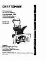
CRR FTSMRW
6 Horsepower
24 Inch Dual Stage
Free-WheelingTrack
120V. Electric Start
SNOWTHROWER
MODEL NO.
536.888400
i
Caution:
Read and follow all Safety
Rules and Operating
Instructions before first use
of this product.
SEARS, ROEBUCK AND CO., Hoffman Estates, IL 60179 U.S.A.
760817 11103/97
Table of Contents
Warranty
Safety Rules
Contents of Shipping Carton
Assembly
Operation
Maintenance
2
2
2-4
4-5
5-8
8-14
15-17
Service and Adjustments
Storage
Troubleshooting
Repair Parts
Engine Repair Parts
Spanish(Espai_ol)
Parts Ordering/Service
17-23
23-24
24
25-34
35-40
41-65
Back Cover
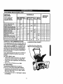
LIMITED TWO-YEAR WARRANTY ON CRAFTSMAN SNOW THROWER
For two years from the date of purchase, when this Craftsman Snow Thrower is maintained, lubricated, and tuned up according to the operating and maintenance instructions in
the owner's manual, Craftsman wilt repair, free of charge, any defect in material or workmanship.
If this Craftsman Snow Thrower is used for commercial or rental purposes, this warranty
applies for only 90 days from the date of purchase.
This warranty does not cover the following:
•
Items which become worn during normal use, such as spark plugs, drive belts and
shear pins.
•
Repairs necessary because of operator abuse or negligence, including bent crank
shafts and the failure to maintain the equipment according to the instructions contained in the owner's manual.
WARRANTY SERVICE IS AVAILABLE BY RETURNING THE CRAFTSMAN SNOW
THROWER TO THE NEAREST CRAFTSMAN SERVICE CENTEWDEPARTMENT
IN
THE UNITED STATES. THIS WARRANTY APPLIES ONLY WHILE THIS PRODUCT IS
IN USE IN THE UNITED STATES.
This warranty gives you specific legal fights, and you may also have other rights which
may vary from state to state.
Sears, Roebuck and Co., D817WA, Hoffman Estates, IL 60179
/_
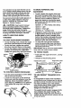
Look for this symbol to point out iroportant safety precautions. It means-ATTENTIONI!! Become alertll! Your safety is Involved.
Z_ CAUTION: Always disconnect spark
plug wire and place wire where it cannot
contact spark plug to prevent accidental
starting when setting-up, transporting,
adjusting or making repairs.
IMPORTANT: Safety standards require
operator presence controls to minimize the
risk of injury. Your snow thrower is
equipped with such controls. Do not attempt
to defeat the function of the operator
)resence control under any circumstances.
California
Proposition
engine exhaust from this
product contains chemicals known
to the State of California to cause
cancer, birth defects or other
reproductiveharm.
1.
Read the operator's manual carefully.
Be thoroughly familiar with the controls
and the proper use of the snow thrower.
Know how to stop the snow thrower and
disengage the controls quickly.
2.
Never allow children to operate the
snow thrower and keep them away
while it is operating. Never allow adults
to operate the snow thrower without
proper instruction. Do not car_ passengers.
Keep the area of operation clear of all
persons, padicularly small children and
pets.
65
WARNING: The
i
TRAINING
3.
4.
Exercise caution to avoid slipping or
falling, especially when operating in
reverse.
PREPARATION
1.
2.
3.
4.
.
Thoroughly inspect the area where the
snow thrower is to be used and
remove all doormats, sleds, boards,
wires and other foreign objects.
Disengage all clutches before starting
the engine (motor).
Do not operate the snow thrower
without wearing adequate winter outer
.garments. Wear footwear that will
=mprove footing on slippery surfaces.
Handle fuel with care; it is highly
flammable.
(a)
(b)
(c)
Use an approved fuel container.
Never remove fuel tank cap or add
fuelto a running engine or hot
engine.
Fill fuel tank outdoors with
extreme care. Never fill fuel tank
indoors .....
(d)
5.
6.
7.
8.
9.
Replace fuel tank cap securely
and wipe up spilled fuel.
(e) Never store fuel or snow thrower
with fuel in the tank inside of a
building where fumes may reach
an open flame or spark.
(f) Check fuel supply before each
use, allowing space for expansion
as the heat of the engine (motor)
and/or sun can cause fuel to
expand.
Use extension cords and receptacles
as specified by the manufacturer for all
snow throwers with electric drive
motors or electric starting motors.
Adjust the snow thrower height to clear
gravel or crushed rock surfaces.
Never attempt to make any adjustments
while the engine (motor)
is running (except when specifically
recommended by the manufacturer).
Let engine (motor) and snow thrower
adjust to outdoor temperatures before
starting to clear snow.
Always wear safety glasses or eye
shields during operation or while
performing an adjustment or repair to
protect eyes from foreign objects that
may be thrown from the snow thrower.
OPERATION
1.
2.
3.
._ _
Do not operate this machine if you are
taking drugs or other medication which
can cause drowsiness or affect your
ability to operate this machine.
Do not use this machine if you are
mentally or physically unable to
operate this machine safely.
Do not put hands or feet near or under
rotating parts. Keep clear of the
discharge opening at all times.
5.
6.
7.
8.
9..
10.
11.
12.
13.
14.
Exercise extreme caution when operating on or crossing gravel drives, walks,
or roads. Stay alert for hidden hazards
or traffic.
After striking a foreign object, stop the
engine (motor), remove the wire from
the spark plug, disconnect the cord on
electric motors, thoroughly inspect the
snow thrower for any damage, and
repair the damage before restarting and
operating the snow thrower.
If the snow thrower should start to
vibrate abnormally, stop the (motor) and
check immediately for the cause. •
Vibration is generally a warning of
trouble.
Stop the engine (motor) whenever you
leave the operating position, before
unclogging the auger/impeller housin9
or discharge guide, and when making
any repairs, adjustments, or inspections.
When cleaning, repairing, or inspecting,
make certain the auger/impeller and a I '=
moving parts have stopped. Disconnect
the spark plug wire and keep the wire
away from the plug to prevent accidental starting.
Take all possible precautions when
leaving the snow thrower unattended.
Disengage the auger/impeller, stop
engine, and remove key.
Do not run the engine indoors, except
when starting the engine and for
transporting the snow thrower in or out
of the building. Open the outside doors;
exhaust fumes are dangerous (containing CARBON MONOXIDE, an ODORLESS and DEADLY GAS).
Do not clear snow across the face of
slopes. Exercise caution when changing
direction on slopes. Do not attempt to
clear steep slopes.
Never operate the snow thrower without
proper guards, plates or other safety
protective devices in place_
Never operate the snow thrower near
glass enclosures, automobiles, window
wells, drep-offs, and the like without
proper adjustment of the snow
discharge angle. Keep children and pets
away.
Do not overload the machine capacity
by attempting to clear snow at too fast a
rate.
15. Never operate the snow thrower at high
transport speeds on slippery surfaces,
Lookbehind and use care when
backing.
. :' •
16. Never direct discharge at bystanders or
allow anyone in front of the snow
thrower.
4.
17. Disengage power to the auged
impeller when snow thrower is
transported or not in use.
18. Use only attachments and accessories approved by the manufacturer
of the snow thrower (such as tire
chains, electric start kits, etc).
19. Never operate the snow thrower
without good visibility or light.
Always be sure of your footing, and
keep a firm
hold on the handles.
Walk; never run.
5.
A
/_
WARNING:
This snow thrower is for
use on sidewalks, driveways and other
ground level surfaces.
_.
MAINTENANCE
AND STORAGE
1. Check shear bolts and other bolts
frequently for proper tightness to be
sure the snow thrower =s in safe
working condition.
2.
Never store the snow thrower with
fuel in the fuel tank inside a
building where ignition sources are
present such as hot water and
space heaters, clothes dryers, and
the like. Allow the engine to cool
before storing in any enclosure.
3.
Maintain or replace safety and instruction labels, as necessary.
Run the snow thrower a few minutes
after throwing snow to prevent freezeup of the auger/impeller.
Caution should be exemi_ed while using on
steep sloping surfaces. DO NOT USE
SNOW THROWER ON SURFACES
ABOVE GROUND LEVEL such as roofs of
residences, garages, porches or other such
structures or buildings.
Always refer to operator's manual
instructions for important details if
the snow thrower is to be stored for
an extended period.
Contents
of Parts Bag (actual size)
1 - Owner's Manual (not shown)
2 - Parts Bags (not shown)
* Non-Assembly Parts ere found In
the toolbox located on top of the
bett cover
*2 - Spare Spacers
3 - Carriage Bolts,
5/16-18xl.00 In.
5 - 11/32 Flatwashers
3 -Hex Nylon Nuts,
5/16-18
*2 - Spare Shear Pine
1- Shifter Knob
1- Nut, 1/2-13 Hexlam
L
1 - Starter Motor Cord 10Ft.
2-Screw,5/16-18
©
x 2 In'.
2 -Washer, Hvsptlk
B©
2- Nut, 5/16-18 Reghex
, in carton (not shown full size)
Pads
2 - Ignition Keys
1 - container 5W30 oil
{Attached to engine in
1 - Snow Chute Assembly
plastic bag)
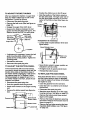
THIS SNOW THROWER HAS A TRACK DRIVE SYSTEM EQUIPPED TO GIVE YOU
FREE-WHEELING
CAPABILITY
If your snow thrower must be moved without the aid of the engine, it will be easier to pull
the snow thrower backward by the handles rather than pushing. For details on how to use
the free-wheeling capability, see the Track Drive/Frae-Wheel Feature paragraph in the
Operation section of this manual.
On start up, the track drive system may be ti_ghtbut wilt loosen up as the snow thrower is
used. After first use, check the track for tension and adjust if necessary. See the Track
Adjustment paragraph in the Service and Adjustments section of this manual. Check track
adjustment and fasteners regularly.
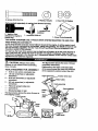
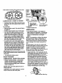
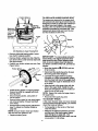
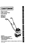
Z_
CAUTION:
The figure below shows the snow thrower
completely assembled.
Always wear safety
glasses or eye shields while assembling
snow thrower.
TOOLS REQUIRED
References to the right or left hand side
of the snow thrower are from the viewpoint
of the operator's position behind the unit.
FOR ASSEMBLY
1 - Knife to cut carton and plasticties
2 - 1/2 inchwrenches (or adjustable
wrenches)
2 - 9116 inch wrenches (or adjustable
wrenches)
2 - 3/4 inchwrenches (or adjustable
wrenches)
1 - Pliers (to spread cotter pin)
1- Screwdriver
Auger (
drive lever
Chute deflector
1 - Measuring tape or ruler
lever
The figure below shows the snow thrower in
the shipping carton.
plate
Clutch
adjustskids
handle
essemb_j
5
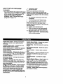
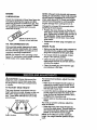
TO REMOVE
SNOW
' FROM CARTON
THROWER
NOTE:
If the cables have become discon-
nected from the clutch levers, reinstall the
• Locate and remove container of 5W30 oil.
• Locate all parts packed separately and
remove from the carton.
NOTE: Place fuel stabilizer in a safe place
until needed for storage.
• * Remove and discard the packing matedal
from around the snow thrower.
• Cut all four comers of the carton from top
to bottom and lay the panels flat.
• Roll the snow thrower off the carton by
pulling on the lower handle. CAUTION:
DO NOT backover cables.
• Remove the packing material from
handle assemblyand plastic protector on
top of auger housing.
• Cut ties secudng the clutch control cables
to the lower handle.
cables as shown in figure below.
NOTE: Position cable through slots on
shifter plate.
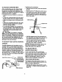
• Install hardware supplied in the parts bag
(Screws, flatwashers, Iockwashers, and
hex nuts) into lower holes on handles.
See figure above.
• Tighten screws in lower holes.
• Rotate upper crank rod into the operating
position. See figure below.
TO INSTALLTHE
UPPER HANDLE
AND CRANK ASSEMBLY
Upper Crank
Rod In
• Loosen, but do not remove the screw,
flatwasher, Iockwasher and hex nut in the
dght hand upper holes of the lower
handle. See next figure.
Upper handle
(Left hand)
• Upper handle
(Right hand)
Eye Bolt
Loosen, but
do not remove
End of Eye
Bolt
• Carefully remove cotter pin and clevis pin
from yoke end of upper crank rod assembly as shown in figure below.
16X2"
Screw
I
UniversalJoint Pin
5/16" Look'washer
Upper
Crank
Rod
• Loosen, but do not remove the nylon
lock,nut on the eye bolt assembly in the
left hand upper holes of the lower handle.
See next figure.
• Cut tie secudng upper crank rod to the
lower crank rod.
NOTE: If this removes the universal joint
and universal joint pin. Place universal
joint into yoke of upper crank rod lining up
large holes. Insert universal joint pin. (Ensure opening in universal joint pin is in line
with small openings in universal joint.)
• Cut tie holding shift rod to lower handle
and move shifter to the first gear.
• Raise upper handle into operating position. Upper handle should be to the
outside of the lower handle.
• While holding universal joint in place slide
the upper crank rod down through the
eye bolt until the universal joint will slide
into the yoke of the lower crank rod_
NOTE: Make sure the cables are not
caught between the upper and lower handle
or on the gear select bracket.
6
• Lineup openings,insertclevispinthrough TO ASSEMBLE SNOW CHUTE
assemblyandsecurewithcotterpin.
crank assembly counterclockwise
Spreadendsofcotterpinto lockin place. • Tum
until it stops.
Seefigurebelow.
• Locate three carriage bolts, flatwashers
and nuts (found in parts bag) from snow
chute flange. DO NOT remove carriage
bolt over worm gear.
__/
Universaljoint
• Position snow chute on snow chute flange
and align the three holes in the snow
chute with holes in the snow chute flange
as shown in figure below.
• Install carriage bolts from inside of chute
as shown in figure below, flatwashers and
nuts.
Upper Crank Rod
• Tighten nut on eye bolt, keeping eye in
line with the rod while tightening the inside securely.
• "13ghtencarriage bolts securely. Be careful
not to overt'_hten. See figure below.
• Tighten screw in right hand upper hole.
•Tum crank assembly clockwise and make
sure all carriage bolts are tight.
TO INSTALL SHIFTER
LEVER KNOB
Locknut
• Thread the hex nut found in the parts bag
onto shifter lever. Thread the shifter lever
knob onto the threaded end of the shifter
lever until it is snug against the hex nut
and the lip is pointed away from the engine. "Rghten hex nut against the bottom
of the shifter lever knob. See figure below.
.Snow Chute
Snow Chute Range
Hex Nut
ShifterLever
e Bolts
TO CHECWADJUSTCLUTCH
CONTROLCABLES
NOTE: If the cables have become disconnected, reinstall spring as shown in figure
below,
The control cables attachedto the auger
clutch lever and traction clutch lever as
shown in figure below may need to be ad-
4" Lg free state
\
3" Lg free state n Auger drive
Traction
_
'_
_ spnng
justed before you use your snow thrower.
For instructions on checking or adjusting
the control cables, (See To Adjust Clutch
ddve
spdng._._._4
Control Cables paragraph on page17),
._-_
Tractic_ndr'we
_'_
/,
Auger ddve
.........
\Co
n
t os
I
N
'HOW TO SET UP YOUR SNOW
THROWER
• Your snow thrower is equipped with height
adjust skids (see second figure on page 5)
on the outside of the auger housing. To
adjust the skid height for different
conditions, (see To Adjust Skid Height
paragraph on page 17).
•/
CHECKLIST
Before you operate your new snow
thrower, to ensure that you receive the
best performance and satisfaction from this
quality product, please review the following
checklist:
v"
All assembly instructions have been
completed.
..-
/
The discharge chute rotates freely.
,/
No remaining loose parts in carton.
While learning how to use your snow
thrower, pay extra attention to the following
important items:
,/,/ Engine oil is at proper level.
,//
,/,/
Auger Drive Lever- Starts and stops the
auger and impeller (snow gathering and
throwing).
Traction Drive Lever- Propels the snow
thrower forward and in reverse.
Speed Shifter Lever- Selects the speed of
snow thrower (6 speeds forward and 2
speeds reverse).
Crank Assembly - Changes the direction of
snow throwing through the discharge chute.
Chute Deflector - Changes the distance
the snow is thrown.
Discharge Chute - Changes the direction
the snow is thrown.
KIIck Pin - Changes the track drive from
normal to free-wheel drive, which allows the
unit to be transported easily without the engine being started.
Weight Transfer System - When engaged
(by lifting up on the upper handle) it helps
keep the snow thrower in contact with the
ground, and reduces ride up on ice and
hard-packed snow. When roleased (by
pushing down on weight transfer pedal with
the ball of your foot), it eases steering of the
snow thrower.
Make sure gas tank is filled properly
with clean, fresh, unleaded gasoline.
Become familiar with all controls-their
location and function. Operate controls
before starting engine.
Helght Adjust Skids - Adjusts the ground
clearance of the auger housing.
Ignition Key - Must be inserted to start the
engine.
Recoil Starter Handle - Starts the engine
manually.
Choke Control - Used to start a cold engine.
Pdmer Button - Injects fuel dfrectly into the
carburetor manifold for fast starts in cold
weather.
Throttle Control - Controls the engine
speed.
Electric Starter Button - Used to start the
engine using the 120 V electric starter.
Shear Pins- Shear pins are designed to
break ( to protect the machine) if an object
becomes lodged in the auger housing. Use
of a harder bolt will destroy the protection
provided by the shear pin.
Toolbox - Spare shear pins and spacers
are located in toolbox.
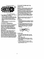
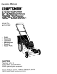
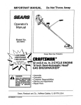
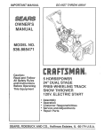
KNOW YOUR SNOW THROWER
READ THIS OWNER'S MANUAL AND SAFETY RULES BEFORE OPERATING YOUR
SNOW THROWER. Compare the illustrations with your SNOW THROWER
to familiarize
youmelf with the location of various controls and adjustments. Save this manual for future
reference.
•
I-I ,
Engine
Start
Engine
Run
Off
Choke On
Fast
Slow
Stop
Fuel
Oil
insert to run
Drive Clutch
((_
Auger Clutch
Pdmer
Button
] engage
k,...) /electdc
/start
Recoil Starter
Handle
Pdmer Button
Auger
Lever
IDriveLever
Lever
Electric
Starter
Button
Throttle
IgniUon Control
Pedal
Toolbox
Height
Skids
Shear Pin
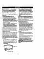
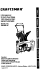
The operation of any snow thrower can re.suit in fol'eign objects being thrown into the
eyes, which can result in severe eye damage. Always wear safety glasses or eye
shields while operating the snow thrower.
We recommend standard safety glasses or
a wide vision safety mask for over your
glasses, available at Craftsman Retail
Stores or Service Centers.
A_
CAUTION:
USEYOUR
SNOW
THROWER
TO STOPYOUR
SNOWTHROWER
AND
• To shift, release the traction drive lever
and move the speed shifter lever to the
speed you desire. Ground speed is determined by snow conditions. Select the
speed you desire by moving the speed
shifter lever into the appropriate area on
the speed selector.
Read owner's manual
before operating machine. Never direct
discharge toward bystanders. Release the
auger control bar and stop the engine
before unclogging discharge chute or auger
housing and before leaving the machine.
HOWTO
TO MOVE FORWARD
BACKWARD
Speeds 1, 2 - Wet, Hea_y, Extra Deep
Speed 3 - Light
Speed 4 - Very Light
Speeds 5, 6 - Transport only
• Engage
in figure
thrower
hold on
thrower
attempt
the traction drive lever as shown
below, left hand. As the snow
starts to move, maintain a firm
the handles, and guide the snow
along the clearing path. Do not
to push the snow thrower.
• To stop throwing snow, release the auger
drive lever (see last figure on this page).
• To stop the track, release the traction
drive lever (see last figure on this page).
• To move the snow thrower backward,
move the speed shifter lever into first or
second reverse and engage the traction
drive lever (left hand).
• To stop the engine, push the throttle control lever to off and pull out (DO NOT
TURN) the ignition key, see figure below.
IMPORTANT: Never move the speed shifter
lever while the traction lever is down.
Ignition Primer
key
TO THROW SNOW
Electdc
• Push down the auger drive lever, see figure below.
• Release to stop throwing snow.
Traction Drive Lever
Auger Drive Lever
oft
Recoil starter
handle
control
control
TO CONTROL SNOW DISCHARGE
Left hand
•Tum the crank assembly to set the direction of the snow throwing.
Right hand
TO USE WEIGHT TRANSFER SYSTEM
• Loosen the wing knob on the chute deflector and move the deflector to set the
distance. Move the deflector (UP) for
more distance, (DOWN) for less distance.
Then tighten the wing knob, see figure
below.
In hard packed or heavy snow conditions,
conventional snow throwers tend to ride up
and leave uneven mounds of snow behind.
For these conditions, your new tracked
snow thrower has a unique weight transfer
system (see first figure on page 11)
designed to minimize ride-up.
knob
The weight transfer system engaged shifts
more weight to the auger housing. This
weight transfer keeps the snow thrower in
contact with the ground and reduces ride-up
on ice and snow.
lO
In lighter snow conditions or when transporting, you should release the weight
transter system for edsier steering.
• To use the weight transfer system, lift up
on upper handle until bracket bolts snap
into place in upper slots of weight transfer
pedal.
• To release, hold upper handle firmly and
push down on the weight transfer pedal
with the ball of your foot.
NOTE: The weight transfer system will not
work if the auger housing height adjust
skids are adjusted to the highest position.
Upper handle
i
BEFORE STARTING THE ENGINE
FILL OIL
NOTE: Engine may already contain some
residual oil Check frequently when filling the
crankcase.
This snow thrower was shipped with a container of 5W30 motor oil. This oil must be
added to the engine before operating. Re-"
move the oil fill cap/dipstick and fill the
crank case to (FULL) line on dipstick (20
ounces) (see figure below). DO NOT
OVERFILL.
Tighten the fill cap/dipstick securely each
time you check the oil level.
For extreme cold operating conditions of
0°F and below, use a partial synthetic 0W30
motor oilfor easier starting.
Oil FiWDipstick
Pedal Upper Slot
TRACK
DRIVE/FREE-WHEEL
FEATURE
The track system on your snow thrower has
a ddve/free-wheel feature (see next figure)
which allows the unit to be transported
easily without the engine being started.
_OTE: Oil level must be
between full and add
mark.
• To use free-wheeling, lift up the loop of
the kUck pin in the front track wheel and
pull the pin out. Install the pin through the
hole in the shaft outside of the track
wheel. Repeat on the opposite side of the
unit.
NOTE: S.A.E. 5W30 motor oil may be used
to make starting easier in areas where the
temperature is 20 ° F. or lower.
FILL GAS
NOTICE: ENGINES WHICH ARE CERTIFIED TO COMPLY WITH CALIFORNIA
AND US EPA EMISSION REGULATIONS
FOR ULGE ENGINES: Are certified to operate on regular unleaded gasoline. Include
the following emission control system(s):
EM, TWC (if So equipped), include any user
adjustable features - therefore no other adjustmants are needed.
• To use normaLdrlve, lift the loop of the
klick pin from the outside hole in the shaft.
Rotate the front track wheel until the hole
in the track wheel hub and the outside
hole in the shaft are in-line. Place pin
through the hole in the track hub. Repeat
on the opposite side of the unit.
NOTE: If unit does not move when engine
is started, check the pin locations. Pins on
both sides of unit should be in the normal
WARNING: Experience indicates that alcohol blended fuels (called gasohol or those
using ethanol or methanol) can attract
drive position for unit to move.
11
moisture which loads to separation and formation of acids during storage. Acidic gas
can damage tho fuel system of an ongine
while in storage.
120 volt A.C. electric starter and recoil
starter. Before starting the engine, be certain that you have read the following information:
To avoid engino probloms, the fuol system
should be emptied before storage for 30
days or longer. Star the engino and let it run
until the fuel lines and carburetor are empty.
Use the carburetor bowl drain to empty residual gasoline from the float chamber. Use
fresh fuel next season (see
Storage instructions on page 23 for additional information).
Never use engine or carburetor cleaner
products in the fuel tank or permanent damage may occur.
Fill the fuel tank with a fresh, clean, unleaded regular, unloaded premium, or
reformulated automotive gasoline only. DO
NOT use leaded gasoline. Be sure that the
container you pour the gasoline from is
clean and free from rust or other foreign particles. Never use gasoline that may be stale
from long periods of storage in the container.
COLD START
Z_
CAUTION:
• Be sure the auger drive and traction drive
levers are in the disengaged (released)
position.
• Move the throttle controRo _ (FAST)
position. See figure on page 9.
• Remove the keys from the plastic bag.
Insert one key into the ignition slot. Be
sure it snaps into place. DO NOT TURN
KEY. Keep the Second key in a safe
place.
• Rotate the choke knob to H choke On
position. See figure on page 9.
• Connect the power cord to the switch box
on the engine.
/_ CAUTION:
This starter is equipped
with a three-wire power cord and plug and is
designed to operate on 120vott AC household current. It must be properly grounded
at all times to avoid the possibility of electrical shock, which may be injurious to operator. Follow all instructions carefully as set
forth in the "To Start Engine" section. Determine that your house wiring is a three-wire
grounded system. Ask a licensed electrician if you are not sure. If your house wire
system is not a three-wire system, do not
use this electric starer under any conditions. If your system is grounded and a
three-hole receptacle is not available at the
point your starter will normally I_e used, one
should be installed by a licensed electrician.
When connecting 120 volt AC power cord,
always connect the cord to the switch box
on the engine first, then plug the other end
into the three-hole grounded receptacle.
When disconnecting power cord, always unplug the end in the three-hole grounded receptacle first.
Gasoline is flammable and
caution must be used when handling or storing it.
Do not fill fuel tank while snow thrower is
running, when it is hot, or when snow
thrower is in an enclosed area.
Keep away from open flame or an electrical
spark and DO NOT SMOKE while filling the
fuel tank.
NEVER till the tank completely. FILL THE
TANK to within 1/4" - 1/2" from the top to
provide space for expansion of fuel.
Always fill fuel tank outdoors and use a funnel or spout to prevent spilling.
Make sure to wipe up any spilled fuel before
starting the engine.
Store gasoline in a clean, approved container and keep the cap in place on the container.
• Plug the other end of the power cord into
a three-hole, grounded 120 volt A.C.
receptacle.
TO STOP ENGINE
• To stop engine, move the throttlecontrol
lever to II (STOP) position and remove
• Push the primer button while covering the
vent hole as follows: (Remove finger
from primer button between primes).
See figure on page 9 for location.
key. Keep the key in a safe place. The
engine will not start without the key.
NOTE: DO NOT rum key.
TO START ENGINE (Electric Starter)
Do not prime if temperature is above
50°F.
Be sure that the engine has sufficient oil.
The snow thrower engine is equipped with a
Two times if tempersture is 50°F to 15°F.
Four times if temperatlJre is below 15°F.
_2
• Pushdownonthestarterbuttonuntilthe
enginestarts.Donotcrankfor more than
10 seconds at a time. This electric starter
is thermally protected. If Overheated it will
stop automatically and can be restarted
only when it has cooled to a safe
temperature (a wait of about 5 to 10
minutes is required).
• When the engine starts, release the
starter button and move choke lever to
"1/2 choke" position. When engine runs
smoothly, move choke lever to =No
Choke" Pos!tion.
• Disconnect the power cord from the
receptacle first and then from the switch
box on engine.
NOTE: Allow the engine to warm up for several minutes before blowing snow in temperatures below 0°F.
• Run the engine at full throttle ,_
when throwing snow.
(FAST)
TO STOP ENGINE
• To stop engine, move the throttle control
lever to Q (STOP) position and remove
key. Keep the key in a safe place. The
engine will not start without the key.
NOTE: DO NOT turn key.
Two times if temperature is 50°F to
15°F.
Four times if temperature is below
15"1:.
• Pull the recoil starter handle rapidly. Do
not allow the handle to snap back, but allow it to rewind slowly while keeping a
firm hold on the starter handle.
• As engine starts warms up move choke
lever to "1/2 choke" position. When
engine runs smoothly, move choke lever
to "No Choke" Position.
NOTE: Allow the engine to warm upfor
several minutes before blowing snow in
temperatures below 0°F.
• Run the engine at full throttle ,_p (FAST)
when throwing snow.
WARM START
If restarting a warm engine after a short
shutdown, leave choke at (OFF) and do
not push the primer button. If the engine
fails to start, follow the Cold Start instructions above.
FROZEN
RECOIL
STARTER
If the starter Is frozen and will not turn
engine:
TO START ENGINE (Recoil Starter)
• Pull as much rope out of the starter as
possible.
Be sure that the engine has sufficient oil.
The snow thrower engine is equipped with a
recoil starter. Before starting the engine, be
certain that you have read the following information:
• Release the starter handle and let it snap
back against the starter.
If the starter still fails to tum engine, repeat
the two previous steps until the starter en-
COLD START
gages. Then continue with the directions for
cold start.
• Be sure the auger drive and traction drive
levers are in the disengaged (released)
position.
To help prevent possible freeze-up of recoil
starter and engine controls, proceed as follows after each snow removal job.
• Move the throttle control to '_ (FAST) position. See figure on page 9 for location.
• With the engine running, pull the starter
rope hard with a continuous full arm
stroke three or four times. Pulling of
starter rope will produce a loud clattering
sound. This is not harmful to the engine
or starter.
• Remove the keys from the plastic bag. Insert one key into the ignition slot. Be sure
it snaps into place. DO NOT TURN KEY.
Keep the second key in a safe place.
• Rotate the choke knob to H choke On
position. See figure on page 9.
• With the engine net running, wipe all
snow and moisture from the carburetor
• Push the primer button, see figure on page
cover in area of control levers. Also move
9, while covering the vent hole as fallows:
throttlecontrol,choke control,and starter
(Remove finger from primer button between primes).
handle several times.
Do not prime if temperature is above
50oR
13
,/_
CAUTION:
Never run engine indoors
.or'_i enclosed, poody vantilated areas. Engine exhaust contains CARBON MONOXIDE, AN ODORLESS AND DEADLY GAS.
Keep hands, feet, hair and loose clothing
away from any moving parts on engine and
snow thrower.
WARNING:
Temperature of muffler and
nearby areas may exceed 150 ° F. Avoid
these areas.
DO NOT allow children or young teenagers
to operate or be near snow thrower while it
is operating.
A_
CAUTION:
Do no attempt to remove
any item that may become lodged in auger
without taking the following precautions:
• On gravel or crushed rock surfaces, set
the skids at 1-1/4" below the scraper bar
(See To Adjust Skids Height paragraph
on page 17). Stones and gravel must not
be picked up and thrown by the machine.
• After the snow throwing job has been
completed, allow the engine to idle for a
few minutes, which will melt snow and
accumulated ice off the engine.
* Clean the snow thrower thoroughly after
each use.
.. _"
. Remove ice and snow accumulation and
all debris from the entire snow thrower,
and flush with water (if possible) to remove all salt or other chemicals. Wipe
snow thrower dry.
PRODUCT
SPECIFICATIONS
• Release auger drive and traction drive
levers.
HORSE POWER:
6HP
• Move throttle lever tO stop position.
DISPLACEMENT:
11.88 cu. in.
• Remove (DO NOT TURN) ignition key.
• Disconnect spark plug wire.
GASOLINE
• Do not place your hands in the auger or
discharge chute. Use a pry bar.
OIL (20 oz. Capacity) :
SNOW
THROWING
CAPACITY:
4 quart
(unleaded)
5W-30
TIPS
SPARK PLUG:
• For maximum snow thrower efficiency in
removing snow, adjust ground speed,
NEVER the throttle. Go slower in deep,
freezing, or wet snow. If the tracks slip, reduce forward speed. The engine is
designed to deliver maximum performance at full throttle and should be run at
VALVE CLEARANCE:
Champion RC19LM
(Gap .030) or
Equivalent
intake: .010 In.
Exhaust: .010 In.
this power setting at all times. Most efficient snow blowing is accomplished when
the snow is removed immediately after it
falls.
• For complete snow removal, slightly overlap each path previously taken. Usa more
overlap in deep snow to prevent overloading.
• The snow should be discharged down
wind whenever possible. In windy conditions, lower the chute deflector to direct
discharged snow close to the ground,
where it is less likely to blow into unwanted areas.
• For normal usage, set the skids so that
the scraper bar is 1/8' above the skids,
For extremely hard-packed snow surfaces,
adjust the skids upward so that the
scraper bar touches the ground.
t4
CUSTOMER
RESPONSIBILITIES
SCHEDULE
SERVICE
RECORDS
SERVICE
DATES
Fill in dates as
you complete
regular service
After
Before As
Every
Every
Each
3efore
first2
Houra
Each
Use
10
25
Season
3torage!
Check Engine Oil Level
Neede¢
Hours Hours
p_'
p4
Change EngineOil
_
Tighten all screws and nuts
Check TractionClutch Cable
t'J
Adjustment(See cable Adj)
p_
_
P_
p/
Reptsca Spark P|ug
_
Replace Drive Belts
Drain Fuel
Check Auger Clutch Cable
Adjustment(See Cable AdD
pJ
i_J
P_
LubricateDisc Ddve Plate Zerk
GENERAL
RECOMMENDATIONS
The warranty on this snow thrower does not
cover items that have been subjected to op
erator abuse or negligence. To receive full
value from the warranty, the operator must
maintain the snow thrower as instructed in
this manual. The above chart is provided to
assist the operator in properly maintaining
the snow thrower.
USE
• Check the tracks for tension and adjust if
necessary (see first figure on page f 6).
• Check the track adjustment and fasteners
regularly.
• Be sure that all fasteners are tight.
AS REQUIRED
_
The following adjustments should be
performed more than once each season.
• All screws and nuts should be checked
often to make sure they are tight, preferable after each use.
• If any parts are worn or damaged,
immediately.
_
t,J
LUBRICATION
CHART
LubricateDisc Ddve Plate Zerk
with a Hi Temp EP Moly Grease.
Some adjustments will need to be made periodicafly to property maintain your snow
thrower.
FIRST
If
p_
Lubricate all pivot points
AFTER
i,J
replace
15
Check track for tension (Pull up g
,at center)
Fdctlon
Wheel
(Require
No
Lubdcation)
LUBRICATION
- EVERY 25 HOURS
• Lubricate Disc Drive Plate every 25 hours
and at the end of the season and/or before
storage.
To Lubricate:
• Remove bottom panel. See second figure
on page 20.
• Position speed selector lever in first gear.
• To grease zerk, use a hand grease gun,
lubricate with a Hi Temp EP Moly grease
See inset of second figure on this page.
DO NOT over fill or allow grease to come
in contact with the disc drive plate or friction wheel or damage will result. Fill zerk
only until grease becomes visible below
bearing assembly located under grease
zerk. See insert in second figure.
IMPORTANT:
Beadng
Placecoiningap
betweenfriction
wheelanddiscddve
plate
[
I
[_3--Graase
Zerk
grease
shouldbe visible
• Hex Shaft and Gears - Hex shaft and
gears require no lubrication. All bearings
and bushings are lifetime lubricated and
require no maintenance. See figure
above.
NOTE: Any greasing or oiling of the above
components can cause contamination of
the friction wheel. If the disc drive plate or
friction wheel comes in contact with grease
or oil, damage to the friction wheel will resuit.
Should grease or oil come in contact with
the disc drive plate or friction wheel, be sure
to clean the plate and wheel thoroughly.
NOTE: For storage, the hex shaft and
gears should be wiped with 5W-30 motor oil
to prevent rusting. See figure above.
Remove coin and ensure that
Re-assemble
Plate
LUBRICATION
• Auger Gear Box - The auger gear box is
lubricated at the factory and should not require additional lubrication. If for some
reason the lubricant should leak out, or if
the auger gear box has been serviced,
add Lubriplate No. 630-AA or equivalent.
Maximum 3 114 ounces should be used.
a gap exists between friction wheel and disc
drive plate.
•
Disc
Friction
Wheel
• Turn disc drive plate clockwise by hand
until grease zerk is clearly visible at front
center. See second figure on this page.
• Place a coin or (a shim of equal thickness) between the rubber friction wheel
and disc drive plate to prevent rubber friction wheel contacting the drive disc.
Shaft
bottom panel.
SNOW THROWER
LUBRICATION - EVERY TEN HOURS
Remove filler plug as seen in figure below
once a year. If grease is visible, do not
add. If grease is not visible, use a piece of
fine wire like a dipstick, to check if there is
grease in the gearbox. Add grease if necessary. Reinstall gear box filler plug.
• Weight Transfer System - Coat weight
transfer side plates with clinging type
grease, such as Lubriplate, every ten
hours and before storage (see Lubrication
Chart on page 15).
NOTE: Clean all excess grease found on
friction disc hub.
CAUTION: Do not allow grease to contact
friction wheel and disc drive plate.
g
16
ENGINE
LUBRICATION
Check the crankcase oil level (see figure below) before starting the engine and after
each five (5) hours of continuous use. Add
S.A.E. 5W30 motor oil as needed. "13ghten
fill cap/dipstick securely each time you
check the oil level.
NOTE: Although multi-viscosity oils improve
starting in cold weather, these multi-viscosity
oils will result in increased oil consumption
when used above 32°F. Check your engine
oil level more frequently to avoid possible
engine damage from running low on oil.
Change the oil every 25 hours and at the
beginning of each season.
• Position the snow thrower so that the oil
drain plug is at the lowest point on the engine. Remove the oil drain plug and the oil
fill cap/dipstick. Drain the oil into a suitable container. Oil will drain more freely
when warm.
• Replace the oil drain plug and tighten securely.
OIL RECOMMENDATION
Only use high quality detergent oil rated
with API service classification SG. Select
the oil's viscosity grade according to your
expected operating temperature:
NOTE: For extreme cold operating conditions of 0 ° and below, use a partial synthetic
0W30 motor oil for easier starting.
SPARK PLUG
• Make sure that the spark plug is tightened
securely into the engine and the spark
plug wire is attached to the spark plug.
• If a torque wrench is available, torque
plug to 18 to 23 foot pounds.
• Clean the area around the spark plug
base before removal to prevent dirt from
entering the engine.
• Clean the spark plug and reset the gap
periodically at .030 inch.
z_CAUTION:
For normal hard sudacas, ad!ust the skids
as follows:
Always disconnect the
spark plug wire and tie back away from
the plug before making any adjustments
or repairs.
TO ADJUST
• Make sure the weight transfer system is
released by holding upper handle firmly
and pushing down weight transfer pedal
with the ball of your foot.
SKID HEIGHT
This snow thrower is equipped with two
height adjustment skids, located on the outside of the auger housing (see figure below). These skids elevate the front of the
snow thrower.
• Loosen the skid mounting nuts (see figure
on this page) and adjust the skids up to
bring the front of the snow thrower down.
Re-tighten the mounting nuts.
• Set the skid on the other side at the same
height.
Nuts
For rocky or uneven surfaces, adjust the
skids as follows:
• Raise the front of the snow thrower by
moving the skids down. This will help prevent rocks and other debris from being
picked up and thrown by the auger.
NOTE: If the skids are at the maximum
Height Adjust Sldds
height, the weight transfer system will not
work.
17
TO ADJUST
SCRAPER
BAR
If adjustment is necessary:.
• Remove fuel from tank, and stand blower
on end.
After consiclerable use, the metal scraper
bar will have a definite wear pattem. The
scraper bar may have to be returned to its
original lower setting to maintain the original
performance level. To adjust:
• Position the snow thrower on a level surface.
• Disconnect the "Z" fitting from drive lever,
• Pull rubber boot off the top of the spring.
Push the cable through the spring (see
figure below) to expose the threaded portion of the cable.
• Loosen the carriage bolts and nuts securing the scraper bar to the auger housing.
• Adjust the scraper bar to the proper position.
Cable spring
• Tighten the carriage bolts and nuts, making sure that the scraper bar is parallel
with the working surface.
• For extended operation, the scraper bar
may be reversed. If the scraper bar must
be replaced due to wear, remove thecarriage bolts and nuts and install a new
scraper bar.
A_ CAUTION:
Be certain to maintain
proper ground clearance for your particular
area to be cleared. Objects such as gravel,
rocks or other debris, if struck by the impeller, may be thrown with sufficient force to
cause personal injuPj, property damage or
damage to the snow thrower.
• Hold the square end of the threaded portion with pliers and adjust the Iocknut in or
out until the excess slack is removed.
• Pull the cable back through the spring
and connect the cable. Do the same for
the other lever cable, if needed.
NOTE: Whenever the traction drive or auger belts are adjusted or replaced, the
cables will need to be adjusted.
TO ADJUST THE CLUTCH CONTROL
CABLES
Periodic adjustment of the cables may be
required due to normal stretch and wear on
the belts. To check for correct adjustment,
the control lever must be in the full forward
position, resting on the plastic bumper. The
control cables are correctly adjusted when
the center of the "Z" fitting is in the center of
the hole and there is no droop in the cable.
See figure below.
TO ADJUST BELTS
AUGER DRIVE BELT
If your snow thrower will not discharge
snow, check the control cable adjustment. If
it is correct, then check the condition of the
auger drive belt. It may be loose or damaged. If it is damaged, replace it (see To
Replace Belts paragraph on page 19).
ControlLever
must be In full
TRACTION
DRIVE BELT
The traction drive belt (see first figure on
page 19) has constant spring pressure and
does not require adjustment.
whenchecking
• Replace the traction drive belt if it is slipping (see To Replace Belts paragraph on
page 19).
P_asticBumper
18
TO REPLACE
BELTS
The drive belts on this'snow thrower are of
special construction and should be replaced
with original equipment belts available from
your nearest Craftsman Store or Service
Center.
• Remove top two bolts that secure auger
housing to motor mount frame. Loosen
bottom two bolts. Auger housing and motor mount frame will separate, hinged by
bottom two bolts.
• Remove old belt from the auger drive pulley.
You will need the assistance of a second
person while replacing the belts.
• Install the original equipment replacement
belt in reverse order of removal.
Drain the gasoline from the fuel tank by removing the fuel line at the carburetor. Drain
the gas into a container and reinstall the
fuel line.
• Position drive belt onto the auger drive
pulley.
,/_ CAUTION:
Drain the gasoline outdoors, away from fire or flame.
AUGER DRIVE BELT
If your snow thrower will not discharge
snow, and the auger drive belt (see figure
below) is damaged, replace it as follows:
• Disconnect the spark plug wire.
Pulley
Drive Belt
• Adjust the belt guides (see To Adjust The
Belt Guides paragraph on page 20).
• Reinstall the belt cover.
• Check clutch control cable adjustment,
see page 18.
• Reconnect spark plug wire.
TRACTION
DRIVE BELT
If your snow thrower will not move forward,
check the traction drive belt (see first figure
on this page for wear (Check other causes
Auger Ddve Belt
Drive also in the Trouble Shooting Points section). If the traction drive belt needs to be
Pulley
replaced, proceed as follows:
• Disconnect the spark plug wire.
(Left Hand)
(Right Hand)
• Remove the belt cover (see last figure on
this page).
• Loosen the belt guides and pull away
from engine drive pulley (see first figure
on this page).
• Loosen nut on auger idler and pull auger
idler pulley away from belt. Note location
of idler pulley for later re-installation.
Pulley
• Remove the belt cover (see figure
below).
• Remove auger drive belt from engine pulley.
• Pull the idler pulley away from the drive
belt, allowing belt to be positioned onto
engine pulley.
\
• Release idler pulley. Ensure idler pulley is
propedy engaged with belt.
• Reinstall auger drive belt.
Belt Cover
• Adjust belt guides (see To Adjust The
Belt Guides paragraph on page 20).
• Adjust idler on auger belt.
• Reinstall the belt cover.
112 Inch self-tappingScrew
• Loosen the belt guides (see first figure on
this page) and pull away from the engine
drive pulley.
• Loosen nut on the auger idler pulley (see
first figure on this page) and pull idler
pulley away from the belt.
• Reconnect the spark plug wire.
• Position the shifter lever in first (1) gear.
TO ADJUST THE BELT GUIDES
• Note the position of the friction wheel on
the disc drive plate. The right outer side of
the disc drive plate should be 3" from the
center of the friction wheel (See figure be-
After you replace the traction or auger drive
belt, you need to adjust one or both of the
belt guides. Proceed as follows:
• Disconnect the spark plug wire.
low).
• Remove the belt cover (See last figure on
page 19).
• Engage the auger drive clutch lever.
• Measure the distance between the belt
guides and the belt (See next figure). The
distance should be 3/32" for each guide.
3/32 Inch
(Right Hand)
Wheel
ira=
---Hex Shaft
bjl_z,p_
_/-jj
Ddve Pulley
Belt Guide
,_
(Left Hand)
3/32 Inch
f
.
•
If adjustment
3"
!
I<
is necessary:
• Loosen bolts in speed selector lever (see
figure below).
-V
Speed Selector Lever
• If adjustment is necessary, loosen the belt
guide mounting bolts. Move the belt
guides to the correct position. Tighten the
mounting bolts.
• Reinstall the belt cover.
L_Bolts to be
loosened
• Reconnect the spark plug wire.
TO ADJUST THE FRICTION
• Move friction wheel to proper position as
indicated in previous step.
WHEEL
If the snow thrower will not move forward,
you need to check the traction drive belt, the
traction drive cable or the friction wheel. If
the friction wheel is damaged, it will need to
be replaced (see the To Replace Friction
Wheel paragraph on pages 20 and 21). If
the friction wheel is not worn, check the ad-
• Re-tighten bolts in speed selector lever.
• Reinstall the bottom panel.
TO REPLACE
If the snow thrower will not move forward,
and the friction wheel is worn or damaged,
you need to replace it as follows: (First allow
the engine to cool).
justment, as follows:
• Disconnect the spark plug wire.
• Drain the gasoline from the fuel tank.
• Drain the fuel in a container and reinstall
the fuel line.
• Drain the gasoline from the gas tank.
• Stand snow thrower on the auger housing
end.
• O_,sc_r_c *,the spark plug w;,re.
• Remove the bottom panel (see figure be-
• Stand the snow thrower up on the auger
housing end (see first figure on page 21).
• Remove the bottom panel (see second
figure on this page).
low).
Remove
FRICTION WHEEL
Bottom Panel
.it
ttom Panel
2O
• Remove the three (3) fasteners securing
the friction wheel to the hub (see second
figure on page 21)..
• Remove the four bolts securing the bearing plates (both sides), (see first figure
on page 21).
FdcUon
TO REPLACE
Bearing
Bolts
Fasteners
AUGER
SHEAR
BOLT
The augers are secured to the auger shaft
with special bolts (see figure below) that are
designed to break (to protect the machine) if
an object becomes lodged in the auger
housing. Use of a harder bolt will destroy the
protection provided by the shear bolt. Your
replacement shear bolts are found in your
tool box located on belt cover.
i
i
i--
Unit
Standing on Auger Housing End
• Remove right side bearing plate. Leave
hex shaft in original position.
IMPORTANT: To ensure safety and perfor-
• Remove friction wheel from hub. Slip friction wheel oft hex shaft towards right side.
See figure below.
• Position new friction wheel onto hub. See
mance levels, only originalequipment shear
bolts should be used. When replacing shear
bolts, be sure to replace shear bolt spacers.
To replace a broken shear bolt, proceed as
follows:
Figure below.
• Move the throttle to O (STOP) and turn
off all controls.
Friction Wheel
Disconnect the spark plug wire. Be sure
all moving parts have stopped.
Shaft
Lubricate the auger shaft by squirting
Lubriplate or a fiber impregnated grease
into the shear bolt hole in the auger shaft.
Then rotate the auger to distribute the oil
in the shaft.
Bolt
• Align the hole in the auger tube with the
hole in the auger shaft, install the new
shear pin and spacer found in toolbox located on top of belt cover.
Nut
• install bearing plates to original position.
Ensure hex shaft is engaged with both
bearing plates.
NOTE: Spacer fits inside the larger hole in
the auger tube.
• Secure bearing plates, using bolts removed earlier.
• Reconnect the spark plug wire.
TO ADJUST TRACK
• Secure friction.wheel to hub using fasteners removed earlier. Ensure hex shaft
it the snow thrower does not move forward
evenly and the track slips slightly, you need to
check the track as follows:
tums freely.
• Should friction wheel require adjustment
(see To Adjust the Friction Wheel on
page 20).
NOTE: Ensure friction wheel and friction
• Pull up gently on the center of the track
near the center.
• Measure the distance between the track
and the top of the track support frame
(see first figure on page 22). The
distance should not be more than one and
disc are free from grease or oil."
• Replace bottom panel•
one-quarter (1-1/4) inches.
21
Track
! adjusted)
TO ADJUST OR REPLACE THE
SPARK PLUG
NOTICE: This spark ignition system meets
all requirements of the Canadian Intederence-Causing Equipment Regulations.
NOTICE: This engine complies with all current Australian and New Zealand limitations
regarding electromagnetic interference.
Track (out of adjustment)
If the distance Is greater, you need to
adjust the track as follows:
• Loosen or tighten the adjusting bolt at the
rear of the track support frame (see figure
above) to obtain the proper distance
between the track and the track support
frame.
If you have difficulty starting your snow
thrower, you may need to bdjust or replace
the spark plug. Follow the instructions below.
Replace the spark plug if the electrodes are
pitted or bumed or if the porcelain is
cracked.
TO ADJUST:
Clean the spark plug by carefully scraping
the electrodes (do not sand blast or use a
wire brush).
• Adjust the track on the opposite side in
the same manner.
TO ADJUST
CARBURETOR
Be sure the spark plug is clean and free
of foreign material. Check the electrodes
gap (see figure below) with a wire feeler
gauge and reset the gap to .030 inch if
necessary.
If you think your carburetor needs adjusting,
see your nearest Authorized Craftsman
Service Center. Engine pedormance
should not be affected at altitudes up to
7,000 feet. For operation at higher elevations, contact your Authorized Craftsman
Service Center.
IMPORTANT: Never tamper with the engine govemor, which is factory set for
proper engine speed. Overspeeding the
engine above the factory high speed setting
can be dangerous. If you think the enginegoverned high speed needs adjusting, contact your nearest Craftsman Service Center,
which has the proper equipment and experience to make any necessary adjustments.
TO REPLACE:
• If you need a new spark plug, use only
the proper replacement spark plug (See
page 14).
• Set the gap to .030.
• Before installing the spark plug, coat its
threads lightly with oil or grease to insure
easy removal.
• Tighten the plug firmly into the engine.
• If a torque wrench is available, torque the
plug to 18 to 23 ft. - Ibs.
22
• If you do not want to remove gasoline,
use fuel stabilizer supplied with unit or
purchase Craftsman Fuel Stabilizer No.
33500. Add fuel stabilizer to any gasoline
left in the tank to minimize gum deposits
and acids. If the tank is almost empty,
mix stabilizer with fresh gasoline in a
To prevent engine damage (if snow thrower is
separate container and add some to the
not used for more than 30 days) follow the
tank.
steps below.
Z_ CAUTION:
Never store your snow
thrower indoors or in an enclosed, poorly
ventilated area if gasoline remains in the
tank. fumes may reach an open flame,
spark or pilot light from a fumaca, water
heater, clothes dryer, cigarette, etc.
SNOW
THROWER
STORAGE
• Thoroughly clean the snow thrower.
• Lubricate all lubrication points (See the
Maintenance section on pages 15-17).
• Be sure that all nuts, bolts and screws are
securely fastened. Inspect all visible moving parts for damage, breakage and wear.
Replace if necessary.
• Touch up all rusted or chipped paint surfaces; sand lightly before painting.
• Cover the bare metal parts of the blower
housing auger and the impeller with rust
preventative, such as a spray lubricant.
Always follow instructions on stabilizer containen Then run engine at least 10 minutes
after stabilizer is added to allow mixture to
reach carburetor. Store snow thrower in a
safe place. See Waming above.
You can keep your engine in good operating
condition during storage by:
• Changing oil (Seepage
14).
NOTE: A yearly checkup or tune-up by a
Craftsman Service Center is a good way to
insure that your snow thrower will provide
maximum performance for the next season.
• Lubricating the piston/cylinder area. This
can be done by first removing the spark
plug and squirting a few drops of clean
engine oil into the spark plug hole. Then
cover the spark plug hole with a rag to
absorb oil spray. Next, rotate the engine
by pulling the starter rope fully out two or
three times. Finally, reinstall spark plug
andattach spark plug wire.
ENGINE STORAGE
OTHER
Gasoline must be removed or treated to prevent gum deposits from forming in the tank,
filter, hose, and carburetor during storage.
Also during storage, alcohol blended gasoline that uses ethanol or methanol (sometimes called gasohol) attracts water. It acts
on the gasoline to form acids which damage
the engine.
• if possible, store your snow thrower indoors and cover it to give protection from
dust and dirt.
• If the machine must be stored outdoors,
block up the snow thrower to be sure the
entire machine is off the ground.
• Cover the snow thrower with a suitable
protective cover that does not retain
moisture. Do not use plastic or vinyl.
IMPORTANT:
Never cover snow thrower
• To remove gasoline, run the engine until
the tank is empty and the engine stops.
Then drain remaining gasoline from carburetor by pressing upward on bowl drain
located on the bottom of carburetor (see
figure below).
while engine and exhaust areas are still
warm.
.Carburetor
.3arburetorBowl
23
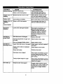
TROIJBLE
Difficult starting
CAUSE
CORRECTION
Defective spark plug
Replace defective plug
Water or dirt in fuel system
Use carburetor bowl drain to
flush and refill with fresh fuel
Engine runs erratlcally
Blocked fuel line or low on fuel
Clean fuel line; check fuel supply; add fresh gasoline (gasoline/oil mixture if 2-cycle engine)
Engine stalls
Unit running on CHOKE
Move choke lever to OFF position
Engine runs erratlcally;
or
Water or dirt in fuel system
Use carburetor bowl drain to
flush and refill with fresh fuel
Loss of power
Excessive
vibration
Loose parts; damaged impeller
Unit fails to
propel itself
Ddve belt loose or damaged
Stop engine immediately and
disconnect spark plug wire.
Tighten all bolts and make all
necessary repairs, If vibration
continues, have the unit serviced by a Craftsman service
repairman
Replace drive belt
Incorrect adjustment of auger con- i Adjust traction drive cable
lrol cable
_/om or damaged friction wheel
Unit fails to
discharge snow
Unit rides up
i Repair frict on wheel
Auger drive belt loose or damaged
Adjust auger drive belt; replace if
damaged
Auger control cable not adjusted
correctly
Adjust auger control cable
Shear bolt broken
Replace shear bolt.
Discharge chute clogged
Stop engine immediately and disconnect spark plug wire. Clean
discharge chute and inside of auger housing
Foreign object lodged in auger
Stop engine immediately and disconnect spark plug wire. Remove
object from auger.
Weight transfer disengaged
Engage weight transfer system
by lifting up on upper handle until
bracket bolts snap into place in
upper slots of weight transfer
_edal.
e
24
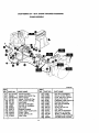
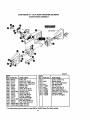
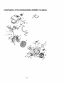
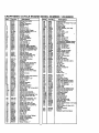
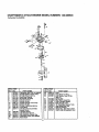
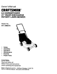
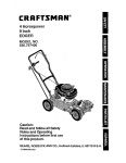
CRAFTSMAI_
24" - 6H.P. SNOW THROWER
ELECTRIC START ASSEMBLY
REF
NO.
6
7
8
9
PART NO.
330783
6216
300302
6219
760817
536.888400
PART NAME
Motor, ElectricStarter
Screw, 1/4-20x.50
Screw #I0 X .50
Cord, Starter Motor
Owner's Manual Eng/Sp
342856A
ENGINE ASSEMBLY
326928F
REF.
NO. PART NO.
10
ENGINE
12
13
31
33
34
710024
120638
3949
120638
910828
41
43
44
3949
120638
910828
PART NAME
Model 143.985503
(See Engine pages)
1..Screw, 5/16-16
-_ Washer, Hvsptlk
Guide, Rod Belt RH
Washer, Hvsptlk
Screw, 5/16-24x1.00
Guide, Rod Belt LH
Washer, Hvsptlk
Screw, 5/16-24xl .00
Note: Always use original equipment parts, Use of
service/replacement
partsotherthan originalparts
may voidyourwarranty.
25
REF,
NO. PART NO.
51
53
57
58
59
60
63
67
68
69
579855
579854
579932
73840
586251
586253
581264
313826
120382
39573
PART NAME
Washer, Crankshaft
Pulley Half V3L
Belt, V 3L 33.13Lg
Fiatwasher .765xl. 12x.06
Spacer, Sleeve
Pulley, Engine
Belt, V 4L
Flatwasher
Washer, RegspUk
Screw, 3/6°24xl.00
All unnumberedItems are
interchangeable with opposite side
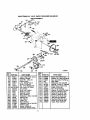
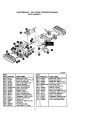
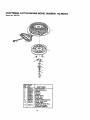
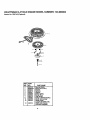
CRAFTSMAN
24" - 6H.P. SNOW THROWER
536.888400
FRAME ASSEMBLY
@
O
O O
®
342573A
REF.
NO. PART NO.
60
88
90
91
100
103
104
10_
106
107
10_
10_
11C
112
761115-833
780055
579760-853
310169
761195
761198
710200
41529
340682
340579
761153
340869
180124
313843
REF.
NO. PART NO.
;PARTNAME
115
133
140
141
142
143
144
145
146
148
149
160
161
162
163
Frame Assembly
Screw, 5/16-18x.50 Tap.
Panel, Bottom
Screw, 1/4-20x.63 Tap.
Plate, Clutch Arm Mtg.
Arm-Clutch
Bolt, 3/8-16 Shoulder
Nut, 3/8-16 Hxctdkjam
Clip, Cable
Bracket,Compact
Cable, Auger Clutch Cont.
Shield, Cable
Screw, 3/8-16xl .25
Idler Pulley
26
41529
313854
579872
180077
73795
579865
71038
313854
180124
313843
41529
760478
310169
71067
760539
PART NAME
Nut, 3/8-16 Hxctrlkjam
Spring, Tension Return
Lever, Idler Arm Traction
Screw, 5/16-18x.75
Flatwasher .328x.125x.075
Bushing,Idler Lever
Nut, 5/16-18 Hexctdk
Idler Spring
Screw, 3/8-16xl .25
Idler Pulley
Nut, 3/8-16 Hexctrlkjam
Belt Cover w/Storage
Screw, 1/4-20x.63 Tap
Flatwasher o281x.63x.066
Lid, Belt Cover Tool Box
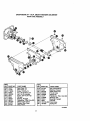
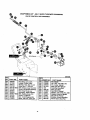
CRAFTSMAN
24" -6H.P. SNOW THROWER
536.888400
DRIVE ASSEMBLY
190
191
192
215
217 216
249
246
25O
;244
235
240
230
REF.
NO. PART NO.
190 579941
191 313853
192
137185
313919
= 193
579937
195
196 11871
198 782585
210 583163-853
2111 583206
215; 583155
216
85501
71074
217
221
73811
222
580969
223
43846
224
580970
225
580961
226
580965
227
578962
228
71059
229
302628
230
334163
270
313995K
275
REF. I
NO, PART NO.
PART NAME
231
235
240
243
'244
!245
246
247
249
250
255
256
270
271
275
276
277
278
Lever, Shaft Tract. Clutch
Bearing, Ranged
Cotter Pin .125xl .00
Return Spring
Lever, Spring Tmc CI."
Screw, 1/4-20x.63
Nut, 1/4-20 Reghexctrik
Disc, Assy Fric. Wheel
Zer, Grease
Shaft, Hex Traction
Bearing, Trunion
Bearing, Trunion
Ring, Retaining
Flatwasher .680xt.12x.06C
Bearing, Ball
Key, Square
Pulley, V3L
Wave Washer
Flatwasher .281x1.00x.063
Washer, Sptlk
Screw, 1/4-20x.75
Bearing & Retainer Assy.
27
780055
579858
579897
462
71074
337029
313883
11871
303008
579858
334163
780055
334163
780055
579893
334163
780055
579867
PART NAME
Screw, 5/16-18x.50 Tap.
Washer, Sp..502x.75x.0605
Hex, Assy #40-STW/PBmg
Ring, Retex
Ratwasher .53xl .00x.063
Bearing, Trunion CI. Releas(
Wheel Assy. Friction Disc
Screw, 1/4-20x.63
Nut, 1/4-20 Hexkeps
Washer, Sp .502x.75x.0605
Bearing & Retainer Assy.
Screw, 5/16-18x,50 Tap.
Bearing & Retainer Assyo
Screw, 5/16-18x.50 Tap.
Jack Assy #41-36T&8T
Bearing & Retainer Assy.
Screw, 5/16-18x.50 Tap.
Chain, Roller#42X40P
CRAFTSMAN
24" - 6H.P. SNOW THROWER
GEAR CASE ASSEMBLY
536.888400
®
®
®
®
®
REF
NO.
300
301
303
304
305
306
310
311
312
313
314
315
PART NO.
10577
10576
710025
46931
303008
9344
9566
50304
48275
340286
51279
51405
REF
NO. PART NO.
PART NAME
Gear Case, RH
Gear Case, LH
Screw, 1/4-20x.75
Nut, 1/4-20 Mac-Lock
Nut, 1/4-20 Hexkeps
Screw, 3/8-16x.50 Tap.
Oil Seal
Beadng, Flanged
Flatwasher .752x1.24x.093
Shaft, Auger Output
Gasket, Gear Case
Gear, Worm
316
320
321
322
323
324
325
326
327
340
1341
431787
50221
583125
580295
454565
48275
313828
50304
9566
760194-853
454565
PART NAME
I Key, Woodruff #61
Bearing, Flanged
Shaft, Worm Imp
Thrust Collar
Spring Pin
Flatwasher .752x1.24x.093
Beadng, Roll
Beadng, Flanged
Oil Seal
Impel Assy.
Spdng Pin
313996B
28
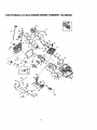
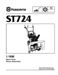
CRAFTSMAN
24" - 6H.P. SNOW THROWER
536.888400
AUGER HOUSING ASSEMBLY
339972F
REF,
NO. PART NO.
PART NAME
1480 583124
Pulley, V4L
481 577400
Screw 5/16-18x.63
482 71371
Square Key .18Sqx.88Lg
485 334514
Spacer, Slev .676xlx.53
490 582960
Retainer, Ball
491 !43846
! Beadng, Ball
493 180077
Screw, 5/16-18x.75
499 710026
Nut, 5/16-15 Reghex
50O 76O810-833 Housing Assy.
502 309235
Ratchet Fastener
504 71003
Screw, 3/8-16x.75
505 120382
Washer, Regsptlk
i Nut, 3/8-16 Hexctdk
506 71111
510 581397-8531 Blade, Scraper 24"
511 340714
Cart. Bolt, 1/4-20x.75
514 I 780285
Nut, 1/4-20 WhlzJock
520 340516-853 Auger Assy LH
521 340523-853 Auger Assy RH
REF.
_10. PART NO.
PART NAME
522
523 3943
524
525 95t7
526 711862
527 9357 "
540 780061
541 340720
542 !120393
543 120638
544 120376
Screw, 1/4o20xl.75
Spacer Sleeve
Nut, 1/4-20 Reghexctdk
Flanged Bearing
Nut, Top Lock
Screw, 5/16-18x.75
Skid, Height Adjust
Carr. Bolt 5/16-18x.75
Flatwasher .344x.69x.065
Washer, HvspUk
Nut, 5/16-18 Reghex
*The replacement part number for Key #522 Is 760875 Shear Pin, Self Locking.
29
CRAFTSMAN
24" - 6H.P. SNOW THROWER
536.888400
TRACK ASSEMBLY
319057D
REF.
NO.
650
652
653
654
655
656
660
661
665
666
667
670
671
672
675
677
678
679
PART NO.
PART NAME
581115
579901
73839
782585
581730
579867
580635-853
313912
316863
302628
Shaft, Axle/Track
Sprocket, Hub #40-21Tx.75
Screw, I/4-20x2.25
Nut, 1/4-20 Reghexctdk
Bearing, Flanged
Chain Roller#42x40P
Plate, Track Direct Dr.
Spdng, Ddve Idler
Baadng,Track
Screw, t/4-20x 75
Nut, 1/4-20 Mac-Lock
Spacer .755x1.20x1.300
Ratwasher .765x1.12x.06
Sprocket,Track Drive
Track, 4.75"
Flatwasher .656xl .31x.07
Ring, Ret.
Pin, Klik .25xl .62
Idler Shaft 4.75" Track
46931
580763
6104
318719
580984
73840
239
322424
580876
r58o
REF.
NO.
681
682
688
689
700
701
702
703
705
706
707
710
711
712
713
3O
PART NO.
579597
318720
579597
302847
580657-853
6001
120638
120378
580652
71072
45171
302618
71067
580634
782585
PART NAME
Flatwasher .656x1.31x.07
Wheel, SD 6.25OD
F atwasher .656xl .31x.07
Cotter Pin .156Diax1.25Lg.
Foot Pedal Assy.
Shoulder Bolt 5/16-18
Washer, Hvsptlk
Nut, 5/16-18 Reghex
Shaft, Foot Pedal 4.75" Trk
Flatwasher .406x.81x.066
Nut, 3/8-16 Whiz-lock
Screw, 1/4-20x3.00
Flatwasher .286x.63x.065
Track Tensioner Bracket
Nut, 1/4-20 Reghexctrlk
CRAFTSMAN
24" - 6H.P. SNOW THROWER
536.888400
HANDLE ASSEMBLY
@
341131A
REF,
NO.
720
724
725
!726
Z27
!726
730
731
733
734
739
741
743
PARTNO.
9552-853
11234
120393
120638
120376
11261
334195
334195
4140
3535
4049
1579
579869
REF,
NO.
744
745
746
750
751
752
753
754
755
i756
PART NAME
PART NO.
1673
782585
308146
339541-853
180079
120638
120376
309436
337407-653
180087
1757 300303
Upper Handle
Screw, 5/16-18x2.75
Flatwasher .344x.69x.065
Washer, HvspUk
Nut, 5/16-18 Reghex
Stop, Red PlasUc
Kit for RH Handle Assy
Kit for LH Handle Assy.
Clutch Pin
Nut, Push On
Bumper, Rect.
Cable, Clutch
Spdng, Tension
31
PART NAME
Spdng, Auger Clutch
Nut, 1/4-20 Reghexctdk
Boot, Clutch Spring
Handle, Lower
Screw 5/16-18xl .00
Washer, HvspUk
Nut, 5/16-18 Reghex
Pushnut, 5/16
Brkt, Gear Selector
Screw, 5/16-18x2.00
Screw, PlasUte
CRAFTSMAN
24" - 6H.P. SNOW THROWER
536.888400
SHIFT YOKE ASSEMBLY
REF.
NO. PART NO.
790 581631-853
791 302628
792 782585
..-._
._: ,._I"_
,,_x
' '
795
796
800
801
802
811
812
813
1
"':
'18486
1304438
;'60564
302628
782585
579944
581795
71111
PARTNAME
Shift Rod
Screw, 1/4-20x.75
Nut, 1/4-20 Reghexctrlk
Nut, 1/2-1.,3Hexjam
Knob, Shift
Lever, Spring
Screw, 1/4-20x.75
Nut, 1/4-20 Reghexctrlk
Bearing, Flanged
Rod, Assy Yoke
Nut, 3/8-16 Reghexctrlk
319053D
_
r
} ""-,
%'..
i
L I
--._.--_
DISCHARGE CHUTE ASSEMBLY
337160E
IEF.
|0.
;82
;83
;84
;88
$92
_93
$94
595
596
597
598
_99
_00
500500_00801
802
_03
804
605
806
607
808
6O9
610
611
I
32
PART NO.
340720
12021
71038
6711
12021
6711
120393
120638
120393
13527
120376
126358
760990-853
760989
11780
305216
586280
120393
71038
760268
760987
585214-853
302628
71067
782585
337227
585193
PART NAME
Can'. Bolt 5/16-18x.75
Washer, Plastic
Nut, 5/16-18 HexNylon
Plastic Wash6r
Plastic Washer
Plastic Washer
Flatwasher .344x.69x.065
Washer, Hvsptik
Flatwasher .344x.69x.065
Knob, T 2 Blade
Nut, 5/16-18 Reghex
Can.. Bolt 5/16-18xl .00
Chute Assy
Chute, Lower
Chute, Upper
Pin, Hinge
Can'. Bolt 5/16-18xl .00
Flatwasher .344x.69x.065
Nut, 5/16-18 Hexnyl
Flap, Chute Insert
Rivet Pop
Collar, Chute Rect.
Screw, t/4-20x.75
Flatwasher .286wx.63x.065
Nut, 1/4-20 Reghexctdk
Retainer, Ring Inner
Retainer, Ring Outer
CRAFTSMAN24_' -
@
6H.P. SNOW THROWER
CHUTE CONTROL ROD ASSEMBLY
536.888400
@
@
@
339545B
REF,
NO. PART NO.
REF,
NO. PART NO
PART NAME
863 578309
'Pin, Clevis
864 578060
Pin, Univ. Join 3/6x1100
865
579493
Pin, Cotter .06x.50
866
581618
Bolt, Eye 3/8-16x6.00
867
148
Grommet, Eye Bolt
868
308145
Boot, Eye Boit
869
124829
Nut, 3/8-16 Hexnyl
87O 71072
Washer, Rat .406x,81x.,066
871
309344
Adapter, Boot to Handle
872
71046
Nut, 3/8-16 Hexnyt
876 585195
Bracket, Worm Moun,ng
877
565196
Worm Gear chute Rot
PART NAME
850 339563
Rod Assy, Upr Crank
851 307399
Handle, Chute Crank
852 309312
Washer, Rat .39x.70x.05
853 578159
Ring, Pet. E..375x.04
854 339198-853 Brkt, Chute Lower Rod Ctd
855 310169
Screw 1/4-20x.63 Wahhtap
857 339560
Rod, Assy Chute Lwr
858 1339534
i Grommet, .401Dx.435WD
859 339507-853 I_rkt,Mating Chute Ctrl
850 _80016
Screw, 1/4-20x.50
851 782585
Nut, 1/4-20 Reghexctrlk
862 578063
Block, Univ Piv .375x.250
33
CRAFTSMAN
24" - 6H.P. SNOW THROWER
536.888400
DECALS
@
I
[]
314005 F
REF.
NO. PART NO.
PART NAME
822 1760971
823
313892
824
70141
825
302922
826
760972
827
761148
828
761079
829
3902
83O 3903
831
340047
833
760983
Decal, 9" Impeller
Decal, Danger Chute
Decal, Danger Auger
Decal, Danger English
Decal, Craftsman
Decal, 6/24 ES
Decal, Danger Chute
Decal, Traction Dr. Engage
Decal, Gear Selector
Decal, Gear Selector
Decal, Toolbox
34
CRAFTSMAN
4-CYCLE ENGINE MODEL NUMBER:
143.985503
119
1
$
37
3701 _
365
38O
222
35
CR.AFI"SMAN 4-CYCLE ENGINE MODEL NUMBER" 143.985503
J
287
/
/
327
36
0
CRAFTSMAN 4-CYCLE ENGINE MODEL NUMBER: 143.985503
Ref.#
Part No,
1
2
4
5
14
15
16
17
18
19
20
25
25A
26
30
35
36
37
38
40
40
41
41
37070
26727
31857
30969
28277
30589
36618
36700
651028
36170
32600
36621
36869
30200
34740
29826
29918
29216
29642
40004
4OO05
36070
36071
42
42
43
45
40006
40007
20381
32875A
46
48
49
50
60
62
64
65
69
70
75
80
81
82
83
86
89
90
92
93
100
101
103
110
110B
119
120
125
125
32610A
35616
36611
37040
36623A
650760
651027
30200
36624
36625
27897
30574A
30590A
30591
36057
650488
610961
611216
650815
650816
34443A
610118
651007
36230
36874
36719
36721
36471
36472
126
126
29314C
29315C
130
130A
135
150
151
153
154
155
157
158
159
160
161
173
178
182
650912
650999
34645
37039
31673
36649
650913
35624A
650914
36629
35626
36630A
651008
36675A
650852
650431
Descdptlon
Cylinder (Incl2&20)
Dowel Pin
Oil Drain Extension
ExtensionCap
Washer
Govemor Rod
Govemor Lever
GovernorLever Clamp
Screw8-32x3/8" TorxT-15
ExtensionSpdng
Oil Seal
Air Baffle(Left)
Air Baffle (Right)
Screw 10-24x9/16"
Crankshaft
Screw, 10-32x3/4"
LockWasher
LockNut, 10-32
RetainingRing
Piston,Pm,&R]ngSet(Std)
Piston,Pin,&RingSet(.010°)
Piston&PinAssy(Std(IncL43)
Piston&PinAssy(.010 OS)
(Incl.43)
Ring Set (Std)
Ring Set (.01 O"OS)
PistonPin RetainingRing
ConnectingRod Assy
(Incl.46 & 49)
ConnectingRod Bolt
Valve Lifter
Oil Dipper
Camshaft (Incl. 253 & 254)
BlowerHsingExtension
Screw8-32x3/8"
Screw 1/4-20x25/32"
Screw 10-24x9/16"
Cylinder Cover Gasket
Cylinder Cover (Inc175-83)
Od Seal
Govemor Shaft.
Washer
GovernorGear Assy.(Inc181)
GovernorSpool
Screw, 1/4-20x1-114"
FlywheelKey
Flywheel
BellevilloWasher
Flywheel Nut
SolidState ignition
Spark PlugCover
ScrewTorx T-15 10-24x15/16
GroundWire
GroundWire
CylinderHead Gasket
CylinderHead (Incl 131)
ExhaustValve (std)(Inc1151)
ExhaustValve(I/32" OS)
(Incl. 151)
Intake Valve (std)(IncL151)
Intake Valve (1/32" OS)
_ncl. 151)
crew 5/16-18x1-1/2"
Screw 5/16-18 x 2-41/64"
ResistorSpark Plug(RN4C)
Vavle Spdng
Valve SpdngCap
Push Rod Guide
Rocker Arm Stud
Rocker Arm
Nut, 1/4-28.
Push Rod
Rocker Arm Cover Gasket
Rocket Arm Cover
Screw 1/4-20x31/64"
BraathorTube
Nut 1/4"-20
Screw 1/4-20 x 1"
Ref.#
Part No.
183
184
185
186
186B
200
206
207
209
215
219
1220
222
!223
224
253
254
260
261
261AI
262
275
277
281
1282
285
287
290
292
1298
300
:301
305
307
:308
309
310
313
325
327
36867
26756
33631
36711
36652
36824A
610973
36632
650821
32410
36868
35438
28820
650451
36581
36701
36702
36871A
651008
650821
651008
36722
650988
36907
651035
35985B
651008
307O5
26460
650665
36875
35355
36877
35499
36651
651011
36878
34080
29443
35392'
328
: 329
I 335
338
340
i 341
J342
342A
350
351
, 355
i 364
i 365 I
35593
610973
86873
650821
37071
36644
651010
650738
570682
32180C
590574
36872
650821
370B
: 370C
370G
3701
! 370P
: 380
I 390
396
400
416
36899
36501
36906
34414
85878
640058
590733
33290E
86720
36085
! 370AI 36261
417
600
900
37
650760
651013
None
Descdption
Choke Bracket
CarburetorTo Intake Pine Gskt
Intake Pipe
GovernorLink
Choke Spdng
ControlBrac,r<et
(Incl. 206)
Terminal
Throttle Link
Screw 10-32 x 1/2"
ControlKnob
Choke Rod
Choke Knob
Screw 10-32 x 1/2"
Screw 1/4o20 x 1"
intake Pipe Gasket
Compression Release Weight
CompressionRelease Spdng
Blower Housing
Screw 114-20x31/64"
Screw, 10-32xl/2"
Screw 1/4-20 x31/64"
Muffler
Screw 1/4-20 x 2-9/32"
Starter Bubble Cover
Screw, 6-32 x 25/64
Starter Cup
Screw 1/4-20x31/64
Fuel Line
Fuel Line Clamp
Screw 1/4-15 x 3/4"
Fuel Tank (loci 292 & 301)
Fuel Cap
Oil Fill Tube
"O" Ring
FillTube Clip
Screw 10-32x5/16"
Dipstick
Spacer
Wire Clip
Starter Plug .--;
_enition Key
rminal
CarburetorCover
Screw 10-32 x 1/2"
Fuel Tank Bracket(Upper)
Fuel Tank Bra;ket (Lower)
Screw 1/4-20x7/3"
Screw, 1/4-20 x 5/8"
•
PrimerAssy
Pdmer Line
Starter Handle (MittenGdp)
CarburetorCover Bracket
Screw 10-32 x 1/2"
LubricationDecal
ControlDecal
Pdmer Decal
InstructionDecal
Warning Decal
Heat Warning Decal
Carburetor(Incl. 184)
Rewind Starter
ElectdcStarter Motor (110 Voll
Gasket Set
S(_park
ArrestorKit(Inc1417)
tional)
Screw 8-32X3/8"
Washer
Replacement Short Block
CRAFTSMAN
4-CYCLE ENGINE MODEL NUMBER; 143.985503
Starter No. 590733
12
I
REF
NO.
0
1
2
3
4
5
6
7
8
11
12
PART
NO.
590733
!590599A
590600
590696
590601
590697
590698
590699
590709
590734
590535
13
590574
PART NAME
Rewind Starter
_vParing
Pin (Incl 4)
sher
Retainer
Washer
Brake Spring
Starter Dog
Dog Spdng
Pulley & Rewind Spring
Starter Hsing Assy
Starter Rope
(Length 98"x9/64" dla,)
MittenGrip Handle
(includedw/starter)
38
CRAFTSMAN
4-CYCLE ENGINE MODEL NUMBER:
Starter No. 590749 (Optional)
REF.
NO.
0
1
2
3
4
5
6
PART
NO.
590749
590599A
590600
590679
590601
590698
590680
590412
590682
11 ;590750
12 590535
13
590574
PART NAME
Rewind Starter
SpringPin (Incl 4)
Washer
Retainer
Washer
Brake Spdng
Starter Dog
Dog Spring
Pulley& Rewind Spdng
Starter Hsing Assy
Starter Rope
MLength98"x9/64" dla.)
itten Grip Handle
(includedw/starter)
39
143.985503
CRAFTSMAN 4-CYCLE ENGINE MODEL NUMBER: 143.985503
Carburetor No.640058
I
]
I
2
--
=
z Ei
[30
28/_"
_
27
36
_D'_37
44 _
4o1"1
REF. PART
NO.
0
2
4
5
10
14
15
16
17
It8
.>0
._0A
._5
27
NO.
640058
631615
631767
631184
'631183
1631036
650506
632118
631890
630735
632164
650417
630766
640018
640053
631951
631024
' REF
NO.
PART NAME
Carburetor (incl 184 on engine)
Throttle Shaft & Lever Ass'y,
ThrotUeReturn Spring
Dust Seal Washer
Dust Seal (Throttle)
Throtter Shutter
Shutter Screw
Choke Shaft & Lever Assy
Choke Shutter
Choke PositioningSpring
Fuel Fitting
Throttle Crack Screw/Idle
Speed Screw
_Tension Spring
Idle RastrictorScrew
Idle RestrictorScrew Cap
Float BowlAssy (Inc132&33)
Float Shaft
28
29
30
31
32
33
36
37
4O
44
47
48
4O
PART
NO.
632019
631028
631021
PART NAME
Float
Float Bowl "O" Ring
Inlet Needle, Seat & Clip
_nc131)
631022
pringClip
27136A BowlDrain Assembly
27554
Drain Plunger Gasket
640019 Main Nozzle Tube
632547 "O' Ring Main Nozzle Tube
64OO59 HighSpeed BowlNut
27110
BowlNut Washer
630748 Welch Plug,Idle MixtureWell
631027 WelchPlug,AtmosphericVent
For":%erepair or replacement parts you
need dehvered dnrectlyto your home' '
Call 7 am-7 pm, 7 days a week
1-800-366-PART
(1-800-366-7278)
Para ordenar piezas con entrega
a domicilio -1-800-659-7084
For in-house major brand repair service
Call 24 hours a day, 7 days a week
1-800-4-REPAIR
(1-800-473-7247)
Para pedir servicio de reparaci6n
domicilio - 1-800-676-5811
a
For the location of a Sears Parts and
Repair Center in your area
Call 24 hours a day, 7 days a week
1-800-488-1222
For information on purchasing a Sears
Maintenance Agreement or to inquire
about an existing Agreement
Call 9 am -5pm, Monday-Saturday
1-800-827-6655
When requesting service or ordering
parts, always provide the following
information:
• Product Type
• Part Number
• " Model Number
• Part Description
America's
Repair
Specialists
Printed In U.S.A.