1
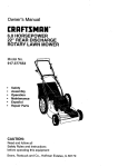
Operator's Manual
3.4 HP, 2-Cycle
53 cc/3.2 cu. in.
235 mph/705 cfm
BACKPACK
AIR BLOWER
Model 360.796900
CAUTION:
Before using this product, read this
manual and follow all Safety Rules and
Operating Instructions.
Sears.
Roebuck and Co., Hoffman
Estates,
V=s=four Craftsman website ;vww sears COmlCrattsman
•
•
•
•
•
•
IL 60179
Safety
Assembly
Operation
Maintenance
Parts
Espa_ol
U.S.A
Dear Valued Customer,
When you operate your new Craftsman air blower don't expect !o hear the high-pitchedengine noise commonly
associatedwith motorizedpower equipment.
L
This is a blower designedto meet the needs of both professionaland occasional users and comply with future noise
and emission standards.Many years of reseamh and engineeringwent intocreating this quieter, more efficientunit.
By redesigningthe engine,fan, and blower housingcomponents, noise emissionswere cut by 50%. Engine speed
was lowered by 2,500 RPM, which reduces noise, fuel consumption,and emissions, while increasing operatingtime
between refuelingwith the added benefit of a longer engine life.
Incorporatinga very powerfulengine and specially designed high volume fan the Craftsman blower is able to achieve
maximum air power at only 4,800 RPM. Competitive blowers typically run at 7,000 to 8,000 RPM. This air blower is
quietand powerful,features you and your neighborswill quicklyappreciate.
•
•
•
•
•
•
•
Warranty
Safety
Contents of Carton
Accessories
Assembly
Operation
Maintenance
Pg.
Pg.
Pg.
Pg.
Pg.
Pg.
Pg.
2
3
4
4
4
5
7
•
•
•
•
•
Storage
Troubleshooting
California Emission Control
Warranty Statement
Parts
Espal_ol
Pg. 8
Pg. 9
Pg.10
Pg.11
Pg.17
LIMITED TWO YEAR WARRANTY
Fortwo (2) years from the date of pumhase if the backpack air blower is maintained, lubricated and tuned up
accordingto the instructionsin the Operator's Manual, Sears will repair or replace, free of charge, any parts found to
be defective in materialor workmanship.If this productis used commemially, this warranty only applies for 90 days.
This warranty does not cover:.
• Exper{_ableitems which become worn during normal use, such as spark plugs and air filters.
•
Repairs necessary because of operator abuse, negligence, improper storage, accident, or the failure to
maintainthe equipmentaccording to the instructionscontained in the Operator's Manual.
Warranty service is available by retumingthe air blower to the nearest Sears Service Center in the United States. This
warrantygives you specificlegal rights,and you may also have other rights which may vary from state to state.
Sears, Roebuck and Co., Dept. 817WA, Hoffman Estates, IL 60179
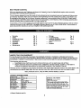
PRODUCT SPECIFICATIONS
Horse Power
3.4
Fuel-Oil Capacity
1.6U.S. qt.
FueFOII Mix
40-1
_sch WSR6F
Spork Rug
IGop .020 In)
3hamplon RCJ--6Y
Air Velo¢_
Z35mph
Air Volume
705cfm
Maximum RPM
_500rpm
20.5Ibs.
Dry Weight
Model No. 360.796900
Serial No.
Date of Pumhase
"rhemodel and serial number will be
found to the left of the fuel cap. You
should record both serial number and
date of pumhase and keep in a safe
place for future reference.
© Sears, Roebuck and Co.
2
CAUTION: Always disconnect spark plug wire and place',Where it cannot contact spark plug to prevent
accidental starting when setting up, transporting, adjusting or making repairs.
•
TRAINING
Read the operator's manual carefuUy.Become familiar
with the controlsand know how to operate your air
blower"properly.
•
•
•
•
•
•
•
Do not allow childrento use your air blower. Never
allow adultsto use air blower without proper
instructions.
Keep the area of operation clear of all persons,
especially small children and pets..
Use air blower only as described in this manual.
Do not operate air blower if it has been dropped or
damaged in any manner. Always have damage
repaired before using your air blower.
Do not use accessory attachmentsthat are not
recommended by the manufacturer. Use of such
attachments may be hazardous.
•
•
•
•
PREPARATION
•
Always wear safety glasses or eye shields when
starting and while usingyour air blower.
•
Dress properly.Do not operate air blower when
barefoot or weadng open sandals. Wear only solid
shoes with good traction.
•
Wear long-sleeved clothesthat are snug fitting.
Avoid wearing loose clothing.
•
Wear either tightlycuffed or cuffless pants.
•
Wear hearing protectioneven when workingfor a
short period of time. Remember - hearingdamage
is cumulative.
• Wear protective,non-slip glovesfor safer
operation_
•
Check fuel.tank before starting engine. Do not fill
fuel tank indoors,when the engine is runningor
when the engine is hot. Allow the engine to cool
for several minutes before fillingthe fuel tank.
Clean off any spilled gasoline before startingthe
engine.
• Always make adjustmentsbefore startingyour air
blower. Never attemptto do this while the engine
is running.
•
Use only in daylightor good artificial light.
Do not put hands or feet near rotatingpads. Keep
clear of the nozzle opening at all times.
Always stop the engine whenever you leave or are
not using your air blower.
Before cleaning, inspecting,or repairingyour air
blower,stop the engine and make absolutelysure
all moving parts have stopped. Then disconnect
the spark plug wire and keep it away from the
spark plug to prevent accidentalstarting.
Do not adjustcarburetor,Overspeeding, engine
damage or personal injurymay result.
Do not operate your air blower if it vibrates
abnormally.Excessivevibration is an indication of
damage; stop the engine, safely check for the
cause of vibrationand repair as needed.
Do not run the engine indoors.Exhaust fumes are
dangerous.
Never operate your air blower without proper
guards, tubes, or other safety devices in place.
WARNING:
CaliforniaProposition65
The engine exhaust from this productcontains
chemicalsknown to the State of Californiato
cause cancer, birth defects, or other reproductive
harm.
MAINTENANCE
•
•
•
•
•
AND STORAGE
Check the engine mountingboltsoften to be sure
they are tightened properly.
Check all bolts, nuts, and screwsat frequent
intervalsfor proper tightnessto be sure air blower
is in safe working condition.
Keep all safety devices in place and working.
To reduce fire hazard, keep the engine free of
debris and excessive grease and oil.
Allow engine to cool before storingin any
enclosure.
Never store air blower with fuel in the tank inside a
buildingwhere fumes may reach an open flame or
an ignitionsource such as hot water heater, spacd
heater, clothes dryer, etc.
CUSTOMER RESPONSIBILITIES
•
Read and observethe Safety Rules.
•
Followa regular schedule in maintaining,
caring and using your air blower.
•
Followthe instructionsunderthe Maintenanceand
Storage sectionsof this manual
OPERATION
•
Keep your eyes and mind on your air blower and
the area being blown. Don't let other interests
distractyou.
•
Always be sure of your footing. Use extra caution
in wet or slipperyareas. WALK - DON'T RUN.
3
.
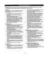
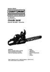
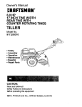
:lead these instructionsand the operating manual in its entirety_beforeyou attemptto operate your new air blower.
BlowerTube
Curved Nozzle Tube
Clamp
(_,
ExtensionTube
Cable Guide
Clamp with
Blower
Pleated Tube
Combi-Wrench
_TO][o.]:
_,,,."[._o_tl
_[.,._
The following items for the operation of your blower are available at your nearest Sears store.
•
Safety goggles
•
Airfilter
•
Hearing protection
• Fuel stabilizer
•
Gloves
• Spark plug
•
2-Cycle air cooled engine oil
• Gas can
V-!.'%'1
_hVd
:]lWd
Read these instructionsand the operating manual in
its entirety before you attempt to assemble or operate
your new backpack air blower.
2.
Your new backpack air blower has been assembled at
the factory except for the blower tubes. The necessary
clamps to complete assembly as well as a combination
wrench are included in the parts bag enclosed with the
unit.
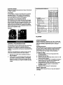
Slidethe pleatedtube (Fig. 2, E) onto the elbow
(Fig. 2, B) and secure with the clamp (Fig. 2, C)
that has an attached cable guide. Install throttle
cable (Fig. 2, D) intothe clamp cable guide.
FIGURE 2
To ensure safe and proper operation of your backpack
air blower, any clamp that you install must be
tightened securely.
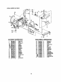
HOW TO ASSEMBLE
1. The elbow tube is already inserted intothe blower
housing. Insure that the two screws (Fig. 1, A) are
tight, but not so tight that the tube cannot be easily
swiveled.
FIGURE 1
3,
4
Loosenthe two screws (Fig. 3, H) on the bottomof
the attached handle clamp. Make sure that the
clamp goes over the top of the raised _ on the
undersideof the blower tube, and that the leg of
the "T" is alignedwith the slot on the clamp. Push
blower tube into the pleated tube and secure with
the plasticclamp (Fig. 3, G). The multi-function
handle (Fig. 3, F) has a 2-inch adjustment range.
Locate the most comfortablehandle location and
4.
-
Once the handle is secured, the blower tube with
handle can be twisted and swiveled. Ensure that
the throttle cable does not become pinched or
trapped when swiveling handle.
.5. Installthe extension tube (if desired) onto blower
tube by aligningthe tab on the extension with the
correspondingarea on blower tube; then push
togetherand twist to secure.
6. Installthe curved nozzle tube in the same manner.
Twist to secure.
then tighten the multi-functionhandle to blower
with the two screws (Fig. 3, H).
FIGURE 3
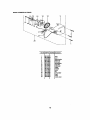
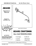
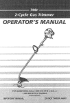
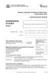
KNOW YOUR BACKPACK
AIR BLOWER
Read this Operator's Manual and Safety Instructionsbefore operatingyour backpack air blower. Compare the
illustrationbelow (Figure 4) with your backpack air blower to familiarize yourselfwith the locationof various controls
and adjustments. Save this manual for future reference.
1.
2.
3.
4.
5.
6.
7.
8.
9.
10.
11.
On-off switch
Throttle lever
Speed lever
Pdmer
Choke lever
Airfilter cover
Fuel tank cap
Starter rope handle
Spark plug
Muffler
Carburetor adjustment screws
12.
13.
14.
15.
16.
17.
18.
19.
20.
21.
22.
FIGURE 4
5
Anti-vibrationsprings
Quick release carryingstrep
Carryingstrap
Carryingfreme
Pleated tube
Blower tube
Extensiontube
Curved nozzletube
Blowerhousing
Clamp
Clamp with cable guide
HOW TO USE YOUR BACKPACK
BLOWER
AIR
GASOUNE AND OIL MIXTURE
Important! Do not use automotive or boat oils in
your air blower. These oilsdo not have proper
additives for 2-cycle, air-cooled enginesand can
cause engine damage.
The 2.cycle engine on this productrequiresa fuel
mixtureof regular unleaded gasolineand a high quality
2-cycle air-cooled engine oil for lubricationof the
bearings and other moving pads. The correctfuel:oil
mixture is 40-1 (see Fuel Mixture Chad). Too littleoil
or the incorrectoil type will cause poor performance
and may cause the engine to overheatand seize.
USING THE MULTI-FUNCTION HANDLE
_Themulti-functionhandle has an on-off switch (Fig. 5,
A), a throttlelever (Fig. 5, B), and a speed lever (Fig.
5, C). It can be rotated to assure the operator's
•comfort.Once started, the speed lever can be set at a
desired RPM. This frees the operator from holdingthe
throttlelever. If not set on maximum RPM and a
• greater RPM is required, simplysqueeze the throttle
lever. To returnto the lower RPM, release the throttle
lever. If the operator plans on blowing at the maximum
RPM for a long period of time, the speed lever is
moved to the =max" setting. If the operator is only
blowingin shortbursts leave the speed lever at the
"min" settingand use the throttle lever to controlthe
speed.
FIGURE 5
Gasoline and oil must be premixed in a clean
approved fuel container. Always use fresh regular
unleaded gasoline. This engine is certifiedto operate
on unleaded 'gasoline.
I
FUELMIXTURECHART
I
GASOLINE
I Gallon
2.5 Gallons
OIL
3+2Dunces
8.0 Dunces
IMPORTANTI Alcohol blended fuels called gasohol
(using ethanol or methanol) can attract moisture,
which leads to oil/gas separation and formationof
acids during storage. Acidic gas can damage the fuel
system of an engine while in storage. To avoidengine
problems,the fuel system should be emptied before
storage of 30 days or longer. Drain the gas tank, then
run the fuel out of the carburetor and fuel lines by
startingthe engine and letting it run until it stops.Usa
fresh fuel next season. See storageinstructionsfor
additionalinfot'mation.Never use engine or carburetor
cleaner produc_sin the fuel tank or permanentdamage
may occur.
STARTING COLD
1. Move on-off switch to the on position identified
with an "1"(Fig. 5).
2. Set speed lever half way between the =rain" '_
and "max"'_ positions(Fig. 5).
3. Move choke lever (Fig. 6, A) to the =START"
position.
4. Press primer bulb (Fig. 6, B) until it is half full and
resistanceis felt.
5. Place left hand on top of the blower housing near
carryinghandle. Pull the starter rope handle'with
right hand slowly until resistance is felt. Then pull
forcefullyand repeatedly until engine attemptsto
start; usually2-3 pulls, no more than 5 pulls.
6. When engine attempts to start, immediately move
choke lever t0 "RUN" posifion.Continue to pull
starter rope handle until engine starts.
2-CYCLE OIL
Craftsman 2-cycle, air-cooled engine oil is specially
blended with fuel stabilizers. If you do not usethis
Sears oil, you can add a fuel stabilizer,such as
Craftsman No. 33500, to your fuel mix.
FUEL STABILIZER
A fuel stabilizer is an acceptable altamative in
minimizingthe formation of fuel gum depositsduring
storage. Add stabilizer to gasoline mixturein fuel
storage container and mix well. Always follow the fuel
mix ratiofound on the stabilizer container. Run engine
at least 5 minutes after adding stabilizerto allow the
stabilizer to reach the carburetor.You do not have to
drain the fuel tank for storage if you are using fuel
stabilizer.
FIGURE 6
6
STARTING WARM
Follow cold startinginstructionsbut leave choke lever
in "RUN" position.
STOPPING
To stop engine, release the throttle lever and adjust
the speed lever to "min_ position.Move switch to
STOP (O) position.In an emergency, immediately
move the switch to the STOP (O) position.
ADJUSTING THE CARRYING STRAPS
Put the blower on your back and yourarms through
the carrying straps as shown.The back plate of the
blower should rest securelyagainst your back. If the
straps need to be tightened (Fig. 7), pull the quick
adjust dng ends downwardas needed. If the straps
need to be loosened, liftthe couplingslocated at the
bottomof the padded straps.
FIGURE 7
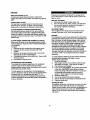
MAINTENANCESCHEDULE
-0
.OWER
Check
for
fasteners
Clean
loose
X
air filter
Inspect
X
muffler
x
4GINE
Replace
spark
Clean
fuel
Clean
fins
onglne
Clean
screen
spark
plug
X
filter
X
cooling
arrestor
X
X
X
X
BLOWER
GENERAL
RECOMMENDATIONS
The warranty on this air blower does notcover items
that have been subjected to operator abuse or
negligence.To receive fullvalue from the warranty,
operator must,maintainair bloweras instructedin this
manual.
All items in the Maintenance sectionof this manual
shouldbe checked at least once each season.
1,
2.
Service more often when operating in dusty or
dirtyconditions.
Once a year you shouldreplace the spark plug
and clean or replace the air filter. A new spark
plug and a clean air filter assure properair-fuel
mixtureand help your engine run batter and last
longer.
CHECK FASTENERS
Check all fasteners, includingnuts, bolts, screws and
clamps, to insure that they are tight and secure. If not,
make all necessary adjustmentspdor to using air
blower.
CLEAN AIR FILTER
Your engine will not run properly and may be damaged
by usinga dirty air filter. Replace air filter element if
deteriorationoccurs. Service more often if you use
your air blower in very dusty or dirty conditions.
To Clean Air Filter
1. Remove air filter cover bytuming black knob
counterclockwise.
2. Remove foam air filter.
3. Shake out air filter. If heavily soiled, rinse in a mild
soap and water solution.
4. Dry air fiifercompletely and oil slightlyby placinga
small amount of oil on filter and kneading until
evenly distdbuted.Wipe off excess oil.
5. Reassemble the air filterand cover; ensure that
the filter is correctly seated in its slot before
reinstallingcover.
6. Replace air filter element if detedorated.
INSPECT MUFFLER
Inspect mufflerevery 25 hours of use and replace if
corroded.
_n[ol :P,_[_
ENGINE
Prepare your backpack air blower for storage at the
end of the season or if the unitwill not be used for 30
days or more.
REPLACE SPARK PLUG
Change your spark plug each year to make your
engine start easy and run better. Set spark plug gap at
.020".
BEFORE STORING
1. Use soap and water to wipe down unit.
2. Be sure that all nuts, bolts, screws, and fasteners
are securelyfastened. Inspectfor damaged or
worn parts. Replace if necessary.
CLEAN FUEL FILTER
The fuel filter is located inside the fuel tank and is
attached to the fuel line. To clean, scrub fuel filter
surface with a small brush, Replace if deteriorated.
BLOWER TUBES
The straightblower tubes can be removed to ease
storage. Use care not to "kink" the throttlecable.
CLEAN ENGINE CYLINDER COOLING FINS
For best performance,keep dirt from accumulating
around the engine cooling fins. Clogged coolingfins
cause the engine to run hotter and shorten engine life.
Coolingfins may be cleaned using a toothbrushor stiff
bristle brush.
ENGINE
It is importantto prevent gum depositsfrom formingin
essentialfuel system parts such as the carburetor,fuel
filter, fuel hose, or tank duringstorage. Also, alcohol
blendedfuels, such as gasohol, ethanol or methanol,
can attractmoisture,which leads to separationand
formation of acids during storage. Acidic gas can
damage the fuel system of an engine while in storage.
Do not store gasolinefrom one season to the next.
Two-cycle mix ages quickly and can cause engine
damage. Replace your gasolinecontainerif it starts to
rust. Rust or dirt in your gasolinewill cause engine
problems.
CLEAN SPARK ARRESTOR SCREEN (if installed)
After every 25 hours of use the spark arrestor screen
must be cleaned. Replace screen if detadorating(part
no. 2048391).
To clean:
1. Remove the four screws from the engine cover.
2. Remove the four screws from the end of the
muffler,
3. Remove the screen and clean with a wire brush.
Replace the screen if deteriorated.
4. Re-installthe screen and muffler end. Secure with
the four screws.
5. Re-installthe engine cover.
To avoid engine problems, the fuel system shouldbe
emptied before storage of 30 days or more.
Followthese instructions:
1. Drain the fuel tank.
2. Start engine and let it run untilthe fuel linesand
carburetorare empty. (The engine willstop.)
3. Use fresh gas next season.
4. If you use a fuel stabilizer, the gasolinecan be left
in the tank. CAUTION: Never store air blower
insidea building with fuel in the tank{ Fumes can
concentrateand possibly reach a source of
ignition. Allow engine to cool before storage.
5. Remove spark plug.
6, Pour a few drops of oil intothe cylinder.
7. Pull the starter handle slowlyto distributethe oil.
8. Replace spark plug,
CARBURETOR ADJUSTMENT
To complywith emission regulations,the carburetor
mixtureis pre-set at the factory and can not be
adjustedwithout propertools. Any adjustment must be
performedby _ service center.
The idle speed'can be adjusted.The idle speed set
screw is located on the top of the unit and to the left of
the spark plug. It is indicated by the letter =r". To
adjustthe idle speed, turn clockwiseto increase and
counterclockwiseto decrease idle speed. Idle speed is
2100 + 100 RPM.
STORAGE TIPS
If possible, store your unit indoorsand cover itto give
it protectionfrom dust and dirt. Do not use plastic.
Plastic cannot breath, which will allowcondensationto
form and will cause your unit to rust. IMPORTANT:
Never cover air blower while engine and mufflerare
stillwarm.
8
I
PROB..BJI
_ON
CAUSE
1. Clean or replaceair filter.
Enginesmokes e._cessively. 1. Dirtyairfilter.
2. Fuelmixtureincorrect.
2. Vedfyyouhave40-1 fuel mixture,
3. Carburetorrequiresmaintenance. 3. ContactSearsSe_ce Center.
Enginehard tostart,will not 1. Fueltankempty.
startor startsand onlyrunsa 2. Engineflooded.
fewseconds.
1. RII tankwi_ correctfuel mi)_
2. Removeand cleansparkplug;with spark plug
removedand engineswitchedoff,crankenginea few
timesto remove e_cessfuel fromcylinder.Reinstall
sparkplug.
3. Sparkplugnotfiring.
3. Replacesparkplug.
4. Didyairfllten
4. Cleanor replaceair filter.
5. Carburetorrequiresadjuslment. 5. ContactSears ServiceCanter,
5. Stalefuel mixorwaterin fuel mix. 6. Draintankand refillwith fresh,dean fuel mix.
Enginewill notaccelerate,
!lacks poweror dies undera
load.
7. Sparkplugwire disconnected.
7. Connectwire toplug.
El.Switchin STOP(O) posilion.
8, Moveswitchto RUN(I) position.
1. Dirtyairfilter.
1. Cleanor replaceair filter.
2. Spark plugfouled.
2. Cleanor replacesparkplugand re-gap(.020").
3. Sparkarrestorscreendogged
(ifapplies).
3. Cleanor replacescreen.
4. Carburetorrequiresmaintenance. 4. Contact Sears Service Canter.
9
'i
The Celifomia Air Resources Board and Sears are pleased to explain the
eadssisn control system warranty on your t 996 and later lawn and garden
equipment engine. In California, now lawn and garden equipment engines
m_sl be des_jned, builf, and equipped to meet the state's stringent anli-smog
standards. Sears must warrant the emission contrdi system on your lawn and
garden equipment engine for the period of time listed below provided there
has been no abuse, neglect, or Improper maintenance of your lawn and
garden equipment engine.
The engine manufacturer is liable for damages to the engine
components caused by the failure of a warranted part still under
warranty.
WHAT IS NOT COVERED
1.
Failures caused by abuse, ne_ect, o_Improper maintenance.
2. ACid-onor mod'dindparts. The use of add-on or mod_lfed parts can
be grounds for disallowing a warranty claim. The engine
manufacturer is not liable to cover failures of warranted parts
caused by the use of add-on or modified parts.
3. Any indirect or cc_.sequentild damages that may result from the
lailum or malfunction of the Sears product. S_ne states do not
allow the exclusion or limitation of consequential damages so
these limitations may not apply to you.
4. Normal sen'ice requirements adelng dudng the warranty period
such as carburetor or ignition adjustment, cleablug, nonnst wea¢.
lubrication, spark plugs, lfhars, starter ropes, etc.
5. Normal service work over and above the repair or replacement of
defective pads.
6. Any failure that results from an accident, customer abuse, noanof
wear, neglect or failure to operate the product in accordance with
the insm._-tlads provided in the Operators Manual or provided
with the prnduct,
7. Pre-delfvePj set-up time.
8. Operslfon of an engine with an lacomlot fuel:o_ ratfo, air filter
removed or speeds in excess of Sears' recommendaUons
ap_icaMa).
9. Transportation costs assoclatnd with dalivedug and ratum of
product to a Sears warranty station.
Your emission control system includes parts such as the caYouratoror fuel
injected system, the ignition system, and connectors end other emlaelonmlatnd a_;sembllas.
Where a warrantable condition exists, Sears will repair your lawn and garden
equipment engine at no cost to you including diagnosis, parts, and labe_
MANUFACTURER'S
WARRANTY
COVERAGE:
"n_e 1996 and later lawn and garden equipment engines are warranted fur two
years. If any emiselon-relatod pan on your engine is defective, the part will be
repaired or replaced by Sears.
OWNER'S WARRANTY
RESPONSIBILITIES:
AS the lawn and garden equipment engthe owner, you are responelb_ for the
performance of the required maintenance listed in your Operator's Manuel.
Sears recommend_ that you retain all receipts covedeg maintenance on your
lawn and g_d_ _
engine. Seem cannot deny warranty solely for the
leek of recelpta o_ tor your fultom to ensure the perfomlance of ell sshedulnd
maintenance.
AS the lawn and garden equipment eugine owner, you should howiNer be
aware that Sears may deny you warranty coverage If your lawn and garden
equipment engine or a part has failed due to abuse, neglect, ir_oropar
maintenance or unapproved moddicat_es.
E.
You are responsible for pmsendng your lawn and garden equipment engine to
a Sears mpelr center as soon as a problem exists. 1he warranty repelm
should be completed in a reasonable amount of _me, not to exceed 30 days.
B,
C.
Warranty claims must be received at Sears within 60 days of the date
of repair noted on the delm.
WARRANTY COMMENCEMENT DATE
The warranty pe_od begins on the date the equipment is purchased by
a reta}l customei_
F°
LENGTH OF WARRANTY COVERAGE
Sears warrants to the initial owner and each subsequent purchaser that
the engine is free from defects in matehals and wedananship for a
period of two years from date of odgfoel purchase from Sears.
G.
WHAT iS COVERED
1.
2.
3.
HOW TO FILE A CLAIM
Warranty claims may be submitted on several c_ffemntforrr_:
Sears Warranty Claim Request
Outdoor Power Equipment Institute
Universal Warranty Claim Report
En_ne Service Assoctalfon Claim
If you have any questions regarding your warranty dghbl and respon_"o4T_es,
you should contact Sears at 1-800-473-7247.
A.
4. CONSEQUENTIAL
DAMAGES
REPAIR OR REPLACEMENT OF PARTS
Raper or replacement of any warranted part will be pedormed at
no cberge to the owner at a warranty station. To locate a
warranty station, you may call Sears it 1-800-473-7247, (24
hours, 7 days I week).
WARRANTY PERIOD
Any warranted bert which Is-not scheduled for rep_cement as
required rnalntenance, or which is scheduled only for regular
inspactfon to the effect of *repair or replace as necdssa_" shall
be warranted for the warranty pedod. Any warranted part which is
scheduled for replacement as required maintenance shall be
warranted for the pedod of time up to the first scheduled
reqlacement point for that part.
H.
WHERE TO GET WARRANTY SERVICE
Warranty eawine or repairs shall be provided at Sears Sewi,.'_ Centers.
Forthe address of a Service Center near you call Sears at 1-800-4737247, {24 hours. 7 days a week).
MAINTENANCE, REPLACEMENT AND REPAIR OF EMISSION
RELATED PARTS
Sears replacement parts must ha used in the pedoanance of any
warranty maintenance or repairs on emlaelen-mlatnd parts and will be
provided without charge during the warranty pedod.
EMISSION CONTROL WARRANTY PARTS LIST
Seam' warranty incfudes the fo_owing parts (ubless said part was
scheduled for tenement
as required maintenance): Air FlfteL,Fuel
Rltor. Carburetor and internal parts, Choke Mechanism, Intake
Manifold, Spark Plug, Flywheel. ign_on Mndute.
MAINTENANCE STATEMENTS
Follow normal maintenance set.Ace, recommended fuel mixl_m (whom
applicable), lubdcatlan, operation and storage of the product as
explained in the Oparatc_'s Manual. The owner shall not be charged for
diugnoslfc labor, which leads to the determination that a warranted dart
is defective, if the diagnostic work is performed at Sears.
DIAGNOSIS
The owner shall _ be charged for diagnostic labor, w_ibh leads
to the determination that a warranted pan la defective, if the
diagnostic work Is performed it Sears.
I0
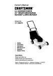
_,
140
135
146
125
--155
///
/
/
--156
f
/
--157
74
_15o
F----95
I
I
21
20
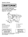
Po_-N_
7
"102
103
104
105
106
107
108
110
111
120
121
122
125
126
128
129
130
" 135
137
138
140
142
145
146
147
150
155
156
157
Pos.-No.Ord,
er..No.
1
2
5
6
10
11
12
13
14
15
17
18
20
21
22
25
26
31
33
34
40
41
42
43
44
45
47
48
49
50
51
52
53
54
57
58
59
50
(57)
(58)
)018346
)016428
)020104
)034135
2300 774
2074294
:)054220
_050102
_31375
2200249
0075101
0052226
0018340
0072140
8033358
2100629
2063334
2280248
2031 117P
0055207"
2011802
2500 732
0018348
8021 256
4063160
2300730
0018363
0072144
2074562
25 O0731
)028100
1072143
_061510
)018421
)084600
3073385
2380 783
Z380 773
:)084600
_073385
783
6259) Z3O0
_072148
63
0018327
70
2061512
71
0018337
72
2074916
73
8021235
74
2061 515
75
2380 805
80
0064407
81
0064436
82
2700322
85
0062321
86
80 62325
87
2074917
88
0010107
90
0062263
91
2074914
95
2800566
180 6880286
101
(1_ 68800286
(103)80 55279
(104) 8069721
screw
activator
nut
cltcfip
fl_heel
sleeve
oilseal
ballbearing
washer
crankshaft
spring
washer
needle
bearing
screw
spring
washer
spacer
tubu
crankcase,
compi.
piston
pin
pistonpindrdip
cylinder
flap
screw
nut
saal
spark
ping
screw
tendon
washer
insulator
muffler
nut
tendon
washer
exhaust
gasket
screw
sparkplugcap
contactslxing
ignition
coil
ignition
coil,compl.,incl.
sparkplugcap
contact
spring
ignition
coil
washer
screw
manifold
gasket
screw
manifold
nut
carburetor
gasket
hose
hose
nng
nng
suction
flange
screw
nng
chokeflap
throttle
cable
s_c'w
exhaust
cover,
incl.
screw
safety
dng
decal
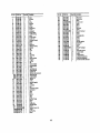
12
Order-No.
:_uantity_p_on
1
4048380
1
8055279
1
8069721
40736790GN 1
4
8018363
1
0069168
1
8069716
1
2073503
3
8018363
4073676DGN 1
12
8018363
0018342
2042667
8018362
0015155
0033393
4061908
4480241
8034135
8020104
4073677DGN
8020101
4036415
4042800
0018362
0080580
1
0510949
1
0510 975
1
0510976
filterplate
safety
ring
decal
enginecover
screw
decal
decal
airguide
Screw
blower
housing
1
screw
screw
damping
plate
screw
screw
spacer
airfiltergasket
fanwheoi
drclip
nut
blower
housing
2
nut
_rotedinn
screen
support
plate
mew
comblwrench
_ket-kit-carburetor
repair-_-carburetor
throttleaxlekit<ahoretor
MODEL
NUMBER
360.796900
I
2
1
Pox'No,_er-No. I quantit 3escdption
1
2
5
8
9
12
13
15
16
17
18
19
20
21
22
25
)01825711
)01833812
!I00 58311
)06319511
ZO74 5691I
Z6O028411
Z07491511
ZO7434311
_0316111
20749771
Z0319651
O0733651
00341261
DO105191
D0341521
26O0293|
13
s_ew
so'ew
starter
housing
start_rope
starter
grip
spring
cassette
ropepulley
stader
pawl
washer
template
spacer
pin
slxing
washer
screw
drdip
starter,
compl.
MODEL NUMBER 360.796900
25
_nt_
Po_-No. _der,No, I QuantityDescription
1
2
5
4073682 I 1
_018363 12
Z700409I I
(7) 1071272 I 1
(8) D067114I 1
(9) 0073351 I 1
(lo) 6063328 I 1
(11) O073_52 I 1
(12) 2700327 I I
7
4071272 I 1
8
0067114 I 1
9
0073351 I 1
10
6063328 I 1
11
0073352 I '1
12
2700327 I 1
15
O061 280I 1
16
27O0395I 1
18
0018274|2
20
0064435 I 1
21
0064300 I 1
25
4O35904 I 1
30
31
32
33
35
40
41
42
45
46
48
50
55
56
57
60
(55)
(56)
(57)
61
ho_omplate
5_ew
fueltank,incl.:
fueltank
socket
r_et
_el pidc-up
fueltank
so_et
el
_mmet
I pi_-up
lidgasket
tanEcap,compl.
screw
hose
hose
carr/ingframe
14
4042577
0073396
6043107
0018363
4046100
0018363
4074126
4074275
4073680
4074962
0098147
0018369
4074921
43O0355
4074412
43 O0332
4074921
43O0335
4074412
0018370
2
4
4
8
2
2
2
2
1
5
1
1
2
2
2
2
2
2
De_ription
tensi_plate
avspnng
flangeplate
screw
tensionbracket
screw
cap
strap
holder
ba_plate
cushion
rivet
back
cushion
scmw
strap
clamp
shoulder
strap
strapholder,
black
shoulder
_ap, inc.:
strapclamp
shoulder
strap
strapholder,
black
screw
MODEL NUMBER 360.796900
Operator's
Manual
40
10
11
1
2
I_.-No. Order-No. _antity
1
2
5
7
8
10
11
15
2O
22
25
26
27
30
33
34
35
36
37
39
4o
4071289
4071288
4400248
0066 399
4071 148
0066 130
0018257
4073124
0020 101
48O0222
O073408
40 73673
O035159
4074938
0018356
0018357
00644151
0084477
28(30566
O084855
1
1
I
I
I _47OlO_
Description
curved
nozzle
tube
extension
tube2
_tmver
tube1
damp,compL
deated
tube
clamp
withcableguide
sere,.,'
elbow
tube
nut
griphalfleft,compL
spdng
throttlelever
washer
outergriphalf
screw
screw
hose
on..off
switch
throttle
cable
on-offcable
Operatur's
Manual
15