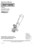
1
Operator's
Manual
M
2-Cycle
WEEDWACKER_ GAS TRIMMER
Model No. 316.791900
W .pI .WJH
_BII_LlffV, CBLI_ _rA_rttif6
TM
t_A S E _
•
•
•
•
•
•
SAFETY
ASSEMBLY
OPERATION
MAINTENANCE
PARTS LIST
ESPANOL, E 13
CAUTION: Before using this product,
read this manual and follow all safety
rules and operating instructions.
Sears, Roebuck
and Co., Hoffman
Visit our website"
769-003836
Estates, IL 60179, U.S.A.
www.sears.com/craftsman
1/08
CALIFORNIA
PROPOSITION
65 WARNING
THE ENGINE EXHAUST FROM THIS PRODUCT CONTAINS
CHEMICALS KNOWN TO THE STATE OF CALIFORNIA TO CAUSE
CANCER, BIRTH DEFECTS OR OTHER REPRODUCTIVE HARM.
TABLE OF CONTENTS
Safety Rules ..........................................
Warranty .............................................
Know Your Unit ........................................
Assembly Instructions ...................................
Oil and Fuel Information .................................
Starting/Stopping
Instructions
............................
Operating Instructions ...................................
Maintenance and Repair Instructions .......................
Cleaning and Storage ...................................
Troubleshooting Chart ...................................
Specifications
........................................
Parts List ............................................
Service Numbers ..............................
SPARK ARRESTOR
The purpose of safety symbols is to attract your attention to possible
dangers. The safety symbols, and their explanations, deserve your
careful attention and understanding. The safety warnings do not by
themselves eliminate any danger. The instructions or warnings they
give are not substitutes for proper accident prevention measures.
SYMBOL
_,
2
4
4
4
5
5
6
7
8
9
10
26
Back Cover
AFETY isALERT:
Indicates
warningpersonal
or caution.
Attention
required in
order to danger,
avoid serious
injury. May be used in conjunction with other symbols or
pictographs.
NOTE:
Advises you of information or instructions vital to the
operation or maintenance of the equipment.
serious injury to yourself or to others. Always follow the
safety precautions to reduce the risk of fire, electric shock
DANGER:
and
personal Failure
injury. to obey a safety warning will result in
injury to yourself Failureto
WARNING:
and others.
obey
Always
a safety
follow
warning
the safety
can precautions
result in
to reduce the risk of fire, electric shock and personal injury.
NOTE
NOTE: For users on U.S. Forest Land and in the states of California,
Maine, Oregon and Washington. All U.S. Forest Land and the state of
California (Public Resources Codes 4442 and 4443), Oregon and
Washington require, by law that certain internal combustion engines
operated on forest brush and/or grass-covered areas be equipped with a
spark arrestor, maintained in effective working order, or the engine be
constructed, equipped and maintained for the prevention of fire. Check
with your state or local authorities for regulations pertaining to these
requirements. Failure to follow these requirements could subject you to
liability or a fine. This unit is factory equipped with a spark arrestor. If
it requires replacement, ask your LOCAL SERVICE DEALER to install the
Accessory Part #753-0516g Spark Arrestor Kit.
MEANING
property damage
CAUTION:
Failure
or personal
to obey injury
a safety
to yourself
warning or
may
to result
others.in
Always follow the safety precautions to reduce the risk of fire
electric shock and personal injury.
Read the Operator's Manual and follow all warnings and safety
instructions. Failure to do so can result in serious injury to the operator
and/or bystanders.
FOR QUESTIONS, CALL 1-800-659-5917
All information, illustrations, and specifications in this manual are based
on the latest product information available at the time of printing. We
reserve the right to make changes at any time without notice.
= IMPORTANT
SAFETY
READ ALL INSTRUCTIONS BEFORE OPERATING
• Read the instructions carefully. Be familiar with the controls and
proper use of the unit.
• Do not operate this unit when tired, ill or under the influence of
alcohol, drugs or medication.
• Children must not operate the unit. Teens must be accompanied
and guided by an adult.
• Inspect the unit before use. Replace damaged parts. Check for
fuel leaks. Make sure all fasteners are in place and secure.
Replace cutting attachment parts that are cracked, chipped or
damaged in any way.
• Use only Hassle Free TM XTRA QUIET Spiral Line. Never use
metal-reinforced line, wire, chain or rope. These can break off
and become dangerous projectiles.
• Be aware of risk of injury to the head, hands and feet.
• Clear the area to be cut before each use. Remove rocks, broken
glass, nails, wire, string and other objects which may be thrown
or become entangled in the cutting attachment. Clear the area of
children, bystanders and pets; keep them outside a 50-foot
(15 m) radius, at a minimum. Even then, they are still at risk from
thrown objects. Encourage bystanders to wear eye protection. If
you are approached, stop the unit immediately.
• Squeeze the throttle control and check that it returns
automatically to the idle position. Make all adjustments or repairs
before using the unit.
FUEL SAFETY WARNINGS
• Store fuel only in containers specifically designed and approved
for the storage of such materials.
INSTRUCTIONS
_
=
I WARNING:
Gasoline is highly flammable and its vapors
can explode if ignited. Take the following precautions:
• Always stop the engine and allow it to cool before filling the fuel
tank. Never remove the fuel tank cap or add fuel when the engine is
hot. Never operate the unit without the fuel cap securely in place.
• Loosen the fuel tank cap slowly to relieve any pressure in the tank.
• Mix and add fuel in a clean, well-ventilated outdoor area where
there are no sparks or flames. Remove the fuel cap slowly, and
only after the engine stops. Do not smoke while fueling or mixing
fuel. Wipe up any spilled fuel from the unit immediately.
• Avoid creating a source of ignition for spilled fuel. Do not start the
engine until fuel vapors dissipate.
• Move the unit at least 30 feet (9.1 m) from the fueling source and site
before starting the engine. Do not smoke. Keep sparks and open
flames away from the area while adding fuel or operating the unit.
WHILE OPERATING
• Never start or run the unit inside a closed room or building.
Breathing exhaust fumes can be fatal. Operate this unit only in a
well-ventilated outdoor area.
• Wear safety glasses or goggles that meet ANSI Z87.1 standards and
are marked as such. Wear ear/hearing protection when operating
this unit. Wear a face or dust mask if the operation is dusty.
• Wear heavy long pants, boots, gloves and a long sleeve shirt. Do
not wear loose clothing, jewelry, short pants, sandals or go
barefoot. Secure hair above shoulder level.
• The cutting attachment shield must always be in place while
operating the unit. Do not operate unit without both trimming
lines extended, and the proper line installed. Do not extend the
trimming line beyond the length of the shield.
I
I
• This unit has a clutch. The cutting attachment remains stationary
when the engine is idling. If it does not, take the unit to a Sears or
other qualified service dealer for an adjustment.
• Adjust the D-handle to your size in order to provide the best grip.
• Be sure the cutting attachment is not in contact with anything
before starting the unit.
• Use the unit only in daylight or good artificial light.
• Avoid accidental starting. Be in the starting position whenever
pulling the starter rope. The operator and unit must be in a stable
position while starting. Refer to Starting/Stopping
Instructions.
• Use the right tool. Only use this tool for its intended purpose.
• Always hold the unit with both hands when operating. Keep a firm
grip on both handles or grips.
• Keep hands, face, and feet away from all moving parts. Do not
touch or try to stop the cutting attachment when it rotates.
• Do not touch the engine, gear housing or muffler. These parts get
extremely hot from operation, even after the unit is turned off.
• Do not operate the engine faster than the speed needed to cut, trim
or edge. Do not run the engine at high speed when not cutting.
• Always stop the engine when cutting is delayed or when walking
from one cutting location to another.
• If you strike or become entangled with a foreign object, stop the engine
immediately and check for damage. Do not operate before repairing
damage. Do not operate the unit with loose or damaged parts.
• Turn the engine to off and disconnect the spark plug for
maintenance or repair.
• Use only replacement parts or accessories recommended for this
tool that are distributed by Sears or a Craftsman outlet. Use of
any replacement parts or accessories purchased elsewhere may
be hazardous, and will also void your warranty.
• Keep unit clean of vegetation and other materials. They may
become lodged between the cutting attachment and shield.
• To reduce fire hazard, replace a faulty muffler and spark arrestor.
Keep the engine and muffler free from grass, leaves, excessive
grease or carbon build up.
OTHER SAFETY WARNINGS
• Never store the unit with fuel in the tank, inside a building where
fumes may reach an open flame (pilot lights, etc.) or sparks
(switches, electrical motors, etc.).
• Allow the engine to cool before storing or transporting. Be sure to
secure the unit while transporting.
• Store the unit in a dry place, secured or at a height to prevent
unauthorized use or damage. Keep out of the reach of children.
• Never douse or squirt the unit with water or any other liquid. Keep
handles dry, clean and free from debris. Clean after each use, see
Cleaning and Storage instructions (p. 11).
• Keep these instructions. Refer to them often and use them to
instruct other users. If you loan this unit to others, also loan them
these instructions.
SAVE THESE INSTRUCTIONS
• SAFETY & INTERNATIONAL
SYMBOLS
•
This operator's manual describes safety and international symbols and pictographs that may appear on this product.
manual for complete safety, assembly, operating and maintenance and repair information.
SYMBOL
MEANING
SYMBOL
Read the operator's manual(s) and follow all warnings
WARNINGREAD OPERATOR'S
and safety instructions.
Failure to doMANUAL
so can result in
[ serous njury to the operator and/or bystanders.
I"
WARNING:
Thrown objects and loud noise can cause
severe eye injury and hearingloss. Wear eye protection
meeting ANSI Z87.1-1989 standards and ear protection when
operating this unit. Use a fullface shield when needed.
WARNING:
small objects Can be propelled at high
speed, causing injury. Keep away from the rotating rotor.
&
Ill I I1| I
• WEAR EYE AND HEARING PROTECTION
MEANING
THROWN OBJECTS AND ROTATING CUTTER CAN
CAUSE SEVERE INJURY
"-z
qdicates danger, warning or caution. May be used in
1* SAFETY
conjunctionALERT
with SYMBOL
other symbols or pictographs.
l_
, KEEP BYSTANDERS AWAY
I
:
WARNING: Keep all bystanders, especially children
and pets, at least 50 feet (15 m.) from the operating area.
i
1
Read the operator's
• HOT SURFACE WARNING
Do not touch a hot muffler or Cylinder. You may get
burned. These parts get extremely hot from operation.
When turned off they remain hot for a short time.
I
,OIL
Refer to 0perator;s manual for the proper type of 0il.
I _N%
UNLEADED
FUELfresh unleaded fuel
[I. Always
use clean,
. PRIMER BULB
Push primer bulbl ful!y and slowly, t0 times,
i" ON/OFF STOP CONTROL
L
I
I
ON / START/RUN
, SHARP BLADE
WARNING:
t
ON/OFFSTOP
CONTROL
jI"OFForSTOP
Sharp blade on cutting attachment shield.
Toprevent serious injury,do not touch the !ine cutting blade.
CRAFTSMAN
FULL WARRANTY
If this Craftsman product fails due to a defect in material or workmanship within two years from the date of purchase, return it to any Sears
store, Parts & Repair Service Center, or other Craftsman outlet in the United States for free repair (or replacement if repair proves impossible).
This warranty applies for only 90 days from the purchase date if this product is ever used for commercial or rental purposes.
This warranty covers ONLY defects in material and workmanship. Sears will NOT pay for:
•
Expendable items that can wear out from normal use within the warranty period, such as cutting line, filters or spark plugs.
•
Repairs necessary because of accident or failure to operate or maintain the product according to all supplied instructions.
•
Preventive maintenance, or repairs necessary due to improper fuel mixture, contaminated or stale fuel.
This warranty gives you specific legal rights, and you may also have other rights which vary from state to state.
Sears, Roebuck and Co., Hoffman Estates, IL 60179
APPLICATIONS
As a trimmer:
•
Cutting grass and light weeds.
•
Edging
•
Decorative trimming around trees, fences, etc.
Other optional accessories may be used with this unit.
On/Off Stop Control
Fuel Cap
Starter
Rope Grip
Shaft Grip
•Throttle Control
D-Handle
Shoulder Strap
Loop
Air Filter/
Muffler Cover
Shaft Housing
Convertible
TM
Coupler
Primer Bulb
Line Cutting
Blade
Trimmer Attachment
Muffler
Spark Plug
Cutting
J
Hassle Free® Plus Cutting Head
INSTALL AND ADJUST THE D-HANDLE
Install
Shaft Grip
1. Place D-handle over the
shaft housing and onto
the bottom clamp (Fig. 1).
Place it a minimum of 6
inches (15.24 cm) from
Minimum 6 it
the end of the shaft grip.
(15.24 cm)
2. Start screws with a flathead or T-25 Torx
screwdriver. Do not
tighten until handle is
adjusted.
Screws
!
4. Tighten the clamp screws evenly until the D-handle is secure.
INSTALLING THE TRIMMER ATTACHMENT
Clamp
Fig. 1
Adjust
3. While holding the unit in the operating position (Fig. 8), position
the D-handle to the location that provides you the best grip.
Prior to use, make sure trimmer attachment is installed correctly.
Please refer to Operating the Convertible TM Coupler System for
proper installation.
NOTE: Remove red cap or hanger from lower shaft housing prior to
assembling to Convertible TM coupler
OILANDFUELMIXING
INSTRUCTIONS
Oldand/or
improperly
mixed
fuelarethemainreasons
fortheunitnot
running
properly.
Besuretousefresh,
cleanunleaded
fuel,Follow
the
instructions
carefully
fortheproper
fuel/oil
mixture.
Definition
ofBlended
Fuels
Today's
fuelsareoftena blendofgasoline
andoxygenates
suchas
ethanol,
methanol,
orMTBE
(ether),
Alcohol-blended
fuelabsorbs
water.
Aslittleas1%waterinthefuelcanmakefuelandoil
separate,
Itformsacidswhenstored,Whenusingalcohol-blended
fuel,usefreshfuel(lessthan60daysold).
UsingBlended
Fuels
Ifyouchoose
tousea blended
fuel,oritsuseisunavoidable,
follow
recommended
precautions:
WARNING:
outdoor area, Carbon
Operate monoxide
this unit only
exhaust
in a well-ventilated
fumes can be
lethal in a confined area.
WARNING:
Avoid accidental
starting.
Make rope
sure (Fig,
you are
in the starting position
when pulling
the starter
5),
To avoid serious injury, the operator and unit must be
in a stable position while starting,
STARTING INSTRUCTIONS
1, Mix gas with oil, See
Oil and Fuel Mixing
Instructions,
• Always use the fresh fuel mix explained in your operator's manual
• Always agitate the fuel mix before fueling the unit
• Drain the tank and run the engine dry before storing the unit
Using Fuel Additives
The bottle of 2-cycle oil that came with your unit contains a fuel
additive which will help inhibit corrosion and minimize the formation of
gum deposits. It is recommended that you use our 2-cycle oil with this
unit. If unavailable, use a good 2-cycle oil de-signed for air-cooled
engines along with a fuel additive, such as STA-BIL_ Gas Stabilizer or
an equivalent, Add 0.8 oz, (23 ml,) of fuel additive per gallon of fuel
according to the instructions on the container. NEVER add fuel
additives directly to the unit's fuel tank,
I _llb
reliability, pay strict attention to the oil and fuel mixing
instructions
onFor
theproper
2-cycleengine
oil container.
CAUTION:
operationUsing
and improperly
maximum
mixed fuel can severely damage the engine,
-_
I
I
Thoroughly mix the proper ratio of 2-cycle engine oil with unleaded
gasoline in a separate fuel can, Use a 40:1 fuel/oil ratio. Do not mix
them directly in the engine fuel tank, See the table below for
specific gas and oil mixing
ratios,
NOTE:
NOTE:
One gallon (3,8 liters)
of unleaded gasoline
mixed with one 3.2
oz. (95 ml,) bottle of
2-cycle oil makes a
40:1 fuel/oil ratio,
Dispose of the old
fuel/oil mix in
accordance to
Federal, State and
Local regulations,
UNLEADED GAS
1 GALLON US
(3.8 LITERS}
1 LITER
2 CYCLE OIL
3.2 FL. OZ.
(95 ml)
25 ml
MIXING RATIO - 40:1
WARNING:
Gasoline
is extremely
vapors may explode.
Always
stop theflammable.
engine andIgnited
allow it
--
to cool before filling the fuel tank. Do not smoke while
filling the tank, Keep sparks and open flames at a distance
from the area.
Fill the fuel tank with
the fuel/oil mixture.
NOTE: There is no need
to turn the unit
on, The On/Off
Stol
Control
the ON ( I )
position at all
Fig. 2
times (Fig. 2),
3,
Fullypress and release _
Primer Bulb
the primer bulb 10 times, _J(..... _
slowly.Some amount of _
- y
_J_
f
fuel should be visible in _
,f __
_"
the primer bulb and fuel
_\ ff / S F_rJ_
lines(Fig. 3).Ifyoucan't
_ / _ / _-JJ
\_
see fuel in the bulb,
\
]}_-J/_/
//
ol}
press and releasethe
\_
l, (_'_-,_l
I/
bulb as many times as it N,_'--J_,\k_
[I
_,)
takes until you can see
\__-_
fuel in it.
Fig. 3
4,
Crouch in the starting
Starting
position (Fig. 4). Do not
Position
squeeze the throttle,
and pull the starter rope
with a controlled and
steady motion until the
unit starts. Wait 10 to
15 seconds, then
squeeze the throttle to
control the cutting
Throttle Control
speed.
NOTE: The unit uses the
Fig. 4
INCREDI-PULL TM starting system, which significantly
reduces the effort required to start the engine. You must pull
the starter rope out far enough to hear the engine attempt to
start. There is no need to pull the rope briskly-- there is no
harsh resistance when pulling. Be aware that this starting
method is vastly different from (and much easier than) what
you may be used to.
IE.. The engine does not start, go back to step 3,
NOTE: If the unit is hot and fails to start within 3 pulls of the
starter rope, squeeze the throttle control and pull the
starter rope until the unit starts.
STOPPING
WARNING:
Remove
to avoid
fuel spray, Never
operatefuel
thecap
unitslowly
without
the fuelinjury
cap from
a source of ignition for spilt fuel. Do not start the engine
until fuel vapors dissipate.
5
INSTRUCTIONS
1,
Release your hand from the throttle control. Allow the
engine to cool down by idling,
2,
Press and hold On/Off Stop Control in the OFF (O) position
until engine comes to a complete stop (Fig. 2),
securely in place.
WARNING:
Add spilled
fuel in fuel
a clean,
well ventilated
outdoor
area. Wipe up any
immediately.
Avoid creating
StarUOn
2,
OPERATING
THECONVERTIBLE
TM
COUPLER
SYSTEM
WARN ING: Before you begin using any attachment, read
and understand the manual that came with the attachment.
Follow all safety information contained within.
CAUTION:
These attachments are to be snapped into
the primary hole only. Using the wrong hole could lead to
personal injury or damage to the unit.
The Convertible
attaachments.
•
•
•
•
•
•
TM
coupler system enables the use of these optional
Edger
Cultivator
Turbo Blower
Brushcutter
Pole Saw
Blade Pruner
damage to the unit, shut the unit off before removing or
WARNING:
To avoid serious personal injury and
installing all attachments.
1.
Turn the knob
counterclockwise to
Convertible
loosen (Fig. 7).
Coupler _
2. Press and hold the
release button (Fig. 5).
3. While firmly holding the
upper shaft housing, pull
the trimmer attachment or
other attachment straight
out of the Convertible TM
coupler (Fig. 6).
REMOVING THE TRIMMER
ATTACHMENT OR OTHER ATTACHMENT
Release Button
TM
__=
Guide Recess
Fig. 5
I,_
release button is fully snapped into the primary hole (Fig. 12),
AUTION:
Before
this unit,
be sure that the
and
that the knob
(Fig.operating
13) is securely
tightened.
NOTE:
To make installing or
attachment
removing theeasier,
place the unit on the
A I
protection
to reduce
thewear
risk of
injury
when foot
operating
this unit.
WARNING:
Always
eye,
hearing,
and body
Before operating the unit, stand in the operating position (Fig. 8).
Check for the following:
• The operator is wearing eye
protection and proper clothing
• With a slightly-bent right arm, the
operator's hand is holding the shaft grip
• The operator's left arm is slightly bent,
the left hand holding the D-handle
• The unit is at waist level
• The trimmer attachment is parallel to
the ground and easily contacts the
grass without the need to bend over
TIPS FOR BEST TRIMMING RESULTS
• Hedge Trimmer
REMOVING THE TRIMMER A'R'ACHMENT OR OTHER ATTACHMENT
I_1_
HOLDING THE TRIMMER
• Keep the trimmer attachment
to the ground.
• Cut from left to right whenever possible.
Fig. 8
Cutting to the right improves the unit's
cutting efficiency. Clippings are thrown away from the operator.
• Trim only when grass and weeds are dry.
• The life of your cutting line is dependent upon:
- Following the trimming tips
- What vegetation is being cut
- Where vegetation is being cut
DECORATIVE TRIMMING
Decorative trimming is accomplished by
removing all vegetation around trees,
posts, fences and more. Rotate the
whole unit so that the trimmer
attachment is at a 30 ° angle to the ground (Fig. 9).
MAINTENANCE
_,__
bench.gr°und
or on a work
___,,
Turn knob
Upper Shaft
Lower Shaft
counterclockwise to
Housing
loosen (Fig. 7).
Housing
2. While firmly holding the
Fig. 6
trimmer attachment or
9O° Edging Hole
other attachment, push it
(Trimmer Only)
straight into the
Convertible TM coupler
until the release button
snaps firmly into the
primary hole (Fig. 6).
NOTE: Aligning the release
button with the guide
Knob
recess will help
Fig. 7
installation (Fig. 5).
1.
3. Turn the knob clockwise to tighten (Fig. 7).
For decorative edging with the line head trimmer attachment or
other attachment, lock the release button of the attachment into the
90 ° hole (Fig. 7).
Fig.9
SCHEDULE
maintenance or repairs with unit running. Always service
and repair a cool unit. Disconnect the spark plug wire to
WARNING:
prevent
ensure that the To
unit
cannotserious
start. injury, never perform
Primary Hole
"_''-'_
parallel
Perform these required maintenance procedures at the frequency
stated in the table. These procedures should also be a part of any
seasonal tune-up.
NOTE: Some maintenance procedures may require special tools or
skills. If you are unsure about these procedures take your unit to
Sears or other qualified service dealer. Call 1-800-4-MY-HOME ®
for more information.
NOTE:
Maintenance, replacement, or repair of the emission
control devices and system may be performed by a Sears
or other qualified service dealer. Call 1-800-4-MY-HOME ®
for more information.
In order to assure peak performance of your engine, inspection of the
engine exhaust port may be necessary after 50 hours of operation. If
you notice lost RPM, poor performance or general lack of acceleration,
this service may be required. If you feel your engine is in need of this
inspection, refer service to a Sears or other qualified service dealer.
Call 1-800-4-MY-HOME ®for more information. DO NOT attempt to
perform this process yourself as engine damage may result from
contaminants involved in the cleaning process for the port.
FREQUENCY
MAINTENANCE
REQUIRED
Before starting
engine
Fill fuel tank with fresh fuel
SEE
p. 6
AIR FILTER MAINTENANCE
Ai
Every 10 hours
Clean and re-oil air filter
p. 8
Every 25 hours
Check and clean spark arrestor
Check spark plug condition and gap
p. 9
p. 9
Every 50 hours
Inspect exhaust port and spark
arrestor screen for clogging or
obstruction
p. 9
LINE REPLACEMENT
Always use Craftsman HassleFree TM XTRA QUIET Spiral
Line. Choose the line size
best suited for the job at
hand. Red colored line is
designed for cutting grass and
small weeds. Black colored
Cuttinc ]ead
line is designed for cutting
larger weeds and light brush.
Fig. 10
NOTE: Before inserting new
line into the holes in
Large Holes
the cutting head,
identify the proper
holes. Follow
directions as shown
on the glide plate. Do
Not attempt to
remove the cutting
head from the unit
when replacing line.
Fig. 11
NOTE: Do not mix lines. Use
Positioning
"runnel
2 black or 2 red only.
1. Remove the old line and
line glide plate from the
cutting head.
2. Clean entire surface of
cutting head.
Glide Plate
Reinstall line glide plate
(Fig. 10). The glide plate is
a keyed item and will only
Fig. 12
fit one way. If it does not go into the cutting head smoothly, DO
NOT force it. Rotate the glide plate until it slides into the cutting
head easily.
NOTE: The glide plate must be installed in the cutting head before
inserting new line.
1.
Push and/or pull the line so that the line is snug against the hub and
is fully extended through the positioning tunnels. (Fig. 12)
6. Correctly installed line will be the same length on both sides.
NOTE: Make sure that when installing new line, that the line is as close
to even as possible. Any variation in lengths may cause the unit
to vibrate excessively. If this happens, stop the unit and make
sure the line is even.
7. Repeat steps 4 thru 6 to install the second trimmer line.
NOTE: Do not rest the Hassle-Free TM PLUS Cutting Head on the
ground while the unit is running.
Some line breakage will occur from:
• Entanglement with foreign matter
• Normal line fatigue
• Attempting to cut thick, stalky weeds
• Forcing the line into objects such as walls or fence posts
NOTE: During normal use the trimming line may become worn
unevenly which may cause excessive vibrations in the unit.
If this becomes uncomfortable or uncontrollable, stop the
unit and replace the line. Refer to the Line Replacement
instructions above.
Fig. 13
Remove the four (4) screws
securing the air filter/
muffler cover (Fig. 13). Use
a flat blade or T20 Torx bit
screwdriver.
/
2.
Pull the cover from the
engine. Do not force.
Cleaning the Air Filter
Failure to maintain your air
filter properly can result in
poor performance or can
cause permanent damage to
Fig. 14
your engine.
1. Remove air filter/muffler
cover. Refer to Removing
the Air Filter/Muffler
Cover above.
2.
3.
4.
5.
Insert both ends of your line through the large holes in the side
of the cutting head (Fig. 11).
5.
Screws
Removing the Air
Filter/Muffler Cover
3.
4.
o vo'0s 'oos0
I
your unit off and allow it to cool before you clean or service it.
The condition of the air filter is
important to the operation of the
unit. A dirty air filter will restrict air
flow and change the air/fuel
mixture.This is often mistaken for Screws<
an out of adjustment carburetor.
Check the condition of the air filter
before adjusting the idle speed
screw. Referto AJ?Filter
Maintenance.
6.
_,
Turn cover over and look
inside to locate the air filter.
Remove the air filter from
inside the air filter/muffler
Fig. 15
cover (Fig. 14).
Wash the filter in detergent
and water (Fig. 15). Rinse
the filter thoroughly.
Squeeze out excess water.
Allow it to dry completely.
Apply enough clean SAE
30 oil to lightly coat the
filter (Fig. 16).
Squeeze the filter to
spread and remove
excess oil (Fig. 17).
Replace the air filter
inside the air filter/muffler
cover (Fig. 14).
j
\
"....
!
Fig. 16
NOTE:
Operating the unit
Fig. 17
without the air filter
and air filter/muffler cover assembly will VOID the warranty.
Reinstalling the Air Filter/Muffler Cover
1. Place the air filter/muffler cover over the back of the carburetor
and muffler. Align the screw holes.
2.
Insert the four (4) screws into the holes in the air filter/muffler
cover (Fig. 13) and tighten. Do net over tighten.
SPARK ARRESTOR
MAINTENANCE
TRANSPORTING
NOTE:
1.
2.
3.
4.
5.
6.
7.
8.
Pay close attention when disassembling the muffler so you
can put it back together correctly. Failure to do so will
damage the unit and may cause serious personal injury.
Remove air filter/muffler cover. Refer to Removing the Air
Filter/Muffler Cover.
Locate the muffler, but do not remove it. Find the screw on the
bottom of the muffler (Fig. 18).This screw holds the Spark Arrestor
Hood Assembly and the spark arrestor screen to the bottom of the
muffler. Remove this screw using either a Torx T20 or flat blade
screwdriver.
Spark Arrestor Hood
Engine
screwdriver,
pry
Using a smallcarefully
flat blade
up the spark arrestor
j
Slo_
hole, taking care to notice
that the "raised" part of
the
spark
arrestor
screen
screen
from
the recessed
_r_ew_
_
is inside the recessed hole. S
Remove the spark arrestor
Tabs
Screen
Muffler
screen from the muffler.
Fig. 18
Clean the spark arrestor screen with a wire brush. Replace it if it
is damaged, or if you are unable to clean it thoroughly.
Reinstall the spark arrestor screen by putting the "raised"
portion of the screen inside the recessed hole of the muffler.
Make sure that the spark arrestor screen fits flat against the
muffler.
Place the spark arrestor hood on top of the spark arrestor plate
with the "raised" side up and the opening facing AWAY from the
engine (Fig. 18). Verify that the exhaust will be directed AWAY
from the engine.
Replace the screw you removed in Step 2 and tighten securely.
Reinstall the air filter/muffler cover (Fig. 13).
screen are not tightened securely, they could fall off causing
I _I_
WARN
theand
spark
arrestor
hood personal
and sparkinjury.
arrestor
damage ING:
to the If
unit
possible
serious
CARBURETOR
ADJUSTMENT
NOTE:
Careless adjustments can seriously damage your unit. Contact
a Sears or other qualified service dealer to make carburetor
adjustments. Call 1-800-4-MY-HOME® for more information.
REPLACING THE SPARK PLUG
Use a Champion RDJ7Y spark plug or equivalent. Remove the plug
after every 25 hours of operation and check its condition.
1.
Stop the engine and allow it to cool. Grasp the plug boot firmly
and pull it from the spark plug.
2.
Clean around the spark plug. Remove the spark plug from the
cylinder head by turning a 5/8-inch socket counterclockwise.
I_
3.
electrodes.
in the
couldscrape
damage
cylinder.
WARNING: Grit Do
not engine
sand blast'
°r the
clean
spark plug I
Replace a cracked, fouled
or dirty spark plug. Set
the air gap at 0.025 in.
(0.635 ram} using a feeler
gauge (Fig. 19).
4.
Install a correctly-gapped
spark plug in the cylinder
|
head. Tighten by turning the
0.025 in.
5/8-inch socket clockwise
(0.635 ram) t
until snug. If using a torque
wrench, torque to:
Fig. 10
110-120 in.°lb. (12.3-13.5 N°m}. Do not over-tighten.
5.
Reattach the plug boot.
_'-
° Allow the engine to cool before transporting.
° Drain fuel from unit.
° Tighten fuel cap before transporting.
° Secure the unit while transporting.
CLEANING
,l_l
WARNING"
avoid
personal
always
tr mmer off and aToow
t to serious
coo before
you cinjury,
ean or
mantaturn
n t.your
Use a small brush to clean off the outside of the unit. Do not use strong
detergents. Household cleaners that contain aromatic oils such as pine
and lemon, and solvents such as kerosene, can damage plastic housing
or handle. Wipe off any moisture with a soft cloth.
STORAGE
° Never store a fueled unit where fumes may reach an open flame or spark.
° Allow the engine to cool before storing.
° Store the unit locked up to prevent unauthorized use or damage.
° Store the unit in a dry, well-ventilated area.
° Store the unit out of the reach of children.
LONG TERM STORAGE
If you plan on storing the unit for an extended time, use the
following storage procedure:
1. Carefully drain the fuel tank by running the unit dry or remove
fuel cap and tip the motor housing over and drain oil/gas fuel
into a container with the same 2-cycle fuel mixture. Do not use
fuel that has been stored for more than 60 days.
2. Start the engine and allow it to run until it stalls. This ensures
that all fuel has been drained from the carburetor.
3.
Allow the engine to cool. Remove the spark plug and put 1 oz.
(30 ml) of any high quality motor oil or 2-cycle oil into the
cylinder. Pull the starter rope slowly to distribute the oil.
Reinstall the spark plug.
NOTE: Remove the spark plug and drain all of the oil from the
cylinder before attempting to start the trimmer after storage.
4. Thoroughly clean the unit and inspect it for any loose or
damaged parts. Repair or replace damaged parts and tighten
loose screws, nuts or bolts. The unit is ready for storage.
PROBLEM
SOLUTION
Primer bulb wasn't pressed enough
Press primer bulb fully and slowly 10 times
Old or improperly mixed fuel
Drain gas tank and add fresh fuel mixture
Plugged spark arrestor
Clean or replace spark arrestor
The outside temperature
is above 90 ° F
Pull the starter rope up to 10-15 times
Old or improperly mixed fuel
Drain gas tank and add fresh fuel mixture
:1#[=tl#I:::U,
vAIm111
#toilf,_T_e.]::1n!::1:r,__/
Old or improperly mixed fuel
Drain gas tank and add fresh fuel mixture
Cutting attachment
Stop the engine and clean the cutting attachment
bound with grass
Plugged spark arrestor
Clean or replace spark arrestor
Old or improperly mixed fuel
Drain gas tank and add fresh fuel mixture
Air filter is plugged
Replace or clean air filter
Plugged spark arrestor
Clean or replace spark arrestor
NEED MORE HELP?
Youq], fk_d, the
a_wwe_: and
mo_e
on mal_agemyhOmeoCOm-
o Find this and at[ your other product manuats ontine.
o Get answers from our team of home experts.
o Get a personatized
o Find information
maintenance
ptan for your home.
and toots to hetp with home projects.
/}fought
te you b_ Sea_'s
for
free!
llillill
Engine Type ............................................................................................................................................................................
Air-Cooled, 2 Cycle
Displacement ........................................................................................................................................................................
31.5 cc (1.95 cu in.)
Idle Speed RPM ......................................................................................................................................................................
2,600 - 3,600 rpm
Operating RPM .................................................................................................................................................................................
6,800+ rpm
Ignition Type .............................................................................................................................................................................
Electronic Ignition
Ignition Switch ..............................................................................................................................................................................
Rocker Switch
Spark Plug Gap ...................................................................................................................................................................
0.025 in. (0.635 mm)
Spark Plug ...................................................................................................................................................
Champion RDJ7Y or equivalent plug
Lubrication ..................................................................................................................................................................................
Fuel/Oil Mixture
Fuel/Oil Ratio .................................................................................................................................................................................................
40:1
Carburetor ......................................................................................................................................................................
Diaphragm, All-Position
Starter ..........................................................................................................................................................
Incredi-Pull TM Starting Auto Rewind
Muffler .....................................................................................................................................................................................
Baffled with Guard
Throttle ..............................................................................................................................................................................
Fuel Tank Capacity .......................................................................................................................................................................
D]:t kvj::E_I:r,_!_1iI;l_ll
Manual Spring Return
13 oz. (384 ml)
n/ I_[ctV,__l
nq_,_[e.]:
hV_l
=1_/ I
Drive Shaft Housing ................................................................................................................................
Steel Tube (Craftsman Convertible TM)
Throttle Control .......................................................................................................................................................................
Finger-Tip Trigger
Approximate Unit Weight (No fuel, with Hassle Free®, shield, and D-handle) ................................................................................
14 Ibs. (6 kg)
Cutting Mechanism .....................................................................................................................................................
Hassle Free TM Plus Head
Trimming Line Diameter .........................................................................................................................
Hassle Free TM XTRA QUIET Spiral Line
All specifications are based on the latest product information
any time without notice.
REPAIR PROTECTION
available at the time of printing. We reserve the right to make changes at
AGREEMENTS
Congratulations on making a smart purchase. Your new Craftsman® product is designed and manufactured for years of dependable
operation. But like all products, it may require repair from time to time. That's when having a Repair Protection Agreement can save you
money and aggravation.
Here is what the Repair Protection Plan Agreement includes:
[]
Expert service by our 10,000 professional repair specialists
[]
Unlimited service and no charge for parts and labor on all covered repairs
[]
Product replacement up to $1500 if your cover product can not be fixed
[]
Discount of 10% from regular price of service and related installed parts not covered by the agreement; also, 10% off regular price of
preventive maintenance checks
[]
Fast help by phone - we call it Rapid Resolution - phone support from a Sears representative. Think of us as a "talking owner's maunal."
Once you purchase the Repair Protection Agreement, a simple phone call is all that it takes for you to schedule service. You can call anytime
day or night, or schedule a service appointment online.
The Repair Protection Agreement is a risk-free purchase. If you cancel for any reason during the product warranty period, we will provide a full refund.
Or a prorated refund anytime after the prodduct warranty period expires. Purchase you Repair Protection Agrrement today!
Some limitations and exclusions apply. For prices and additional information
call 1-800-827-6655.
*Coverage in Canada varies on some items. For full datails call Sears Canada at 1-800-361-6665.
Sears Installation Service
For Sears professional installation of home appliances,
Canada call 1-800-4-MY-HOME ®.
garage door openers, water heaters, and other major home items, in the U.S.A. or
10
CALIFORNIA
/ EPA EMISSION CONTROL WARRANTY
STATEMENT
Your Warranty Rights and Obligations
The California Air Resources Board, the Environmental Protection Agency, and Sears, Roebuck and Co. (Sears) are pleased to explain the emission
control system warranty on your 2007 and later small off-road engine. In California and the 49 states, new small off-road engines must be designed,
built and equipped to meet the state's stringent anti-smog standards. Sears must warrant the emission control system on your small off-road engine
for the periods of time listed below provided there has been no abuse, neglect or improper maintenance of your small off-road engine.
Your emission control system may include parts such as the carburetor or fuel-injection system, the ignition system, and catalytic converter. Also
included may be hoses, belts, connectors and other emission-related assemblies.
Where a warrantable condition exists, Sears will repair your small off-road engine at no cost to you including diagnosis, parts and labor.
The 2007 and later small off-road engines are warranted for two years. If any emission-related part on your engine is defective, the part will be repaired
or replaced by Sears.
Owners Warranty Responsibilities
As the small off-road engine owner, you are responsible for the performance of the required maintenance listed in your operator's manual. Sears
recommends that you retain all receipts covering maintenance on your small off-road engine, but Sears cannot deny warranty solely for the lack
of receipts or for your failure to ensure the performance of all scheduled maintenance.
•
As the small off-road engine owner, you should however be aware that Sears may deny you warranty coverage if your small off-road engine
or a part has failed due to abuse, neglect, improper maintenance or unapproved modifications.
•
You are responsible for presenting your small off-road engine to a Sears Authorized Service Center as soon as a problem exists. The
warranty repairs should be completed in a reasonable amount of time, not to exceed 30 days.
If you have any questions regarding your warranty rights and responsibilities, you should call f-800-4-MY-NOME
®.
Manufacturer's Warranty Coverage
•
The warranty period begins on the date the engine or equipment is delivered to the retail purchaser.
•
The manufacturer warrants to the initial owner and each subsequent purchaser, that the engine is free from defects in material and
workmanship which cause the failure of a warranted part for a period of two years.
•
Repair or replacement of warranted part will be performed at no charge to the owner at an Authorized Sears Service Center. For the nearest
location please contact Sears at: f-800-4-MY-NOME
®.
•
Any warranted part which is not scheduled for replacement, as required maintenance or which is scheduled for only for regular inspection
to the effect of "Repair or Replace as Necessary" is warranted for the warranty period. Any warranted part which is scheduled for
replacement as required maintenance will be warranted for the period of time up to the first scheduled replacement point for that part.
•
The owner will not be charged for diagnostic labor which leads to the determination that a warranted part is defective, if the diagnostic work
is performed at an Authorized Sears Service Center.
•
The manufacturer is liable for damages to other engine components caused by the failure of a warranted part still under warranty.
•
Failures caused by abuse, neglect or improper maintenance are not covered under warranty.
•
The use of add-on or modified parts can be grounds for disallowing a warranty claim. The manufacturer is not liable to cover failures of
warranted parts caused by the use of add-on or modified parts.
•
In order to file a claim, go to your nearest Authorized Sears Service Center. Warranty services or repairs will be provided at all Authorized
Sears Service Centers.
•
Any manufacturer approved replacement part may be used in the performance of any warranty maintenance or repair of emission related
parts and will be provided without charge to the owner. Any replacement part that is equivalent in performance or durability may be used
in non-warranty maintenance or repair and will not reduce the warranty obligations of the manufacturer.
Emission Warranty Parts List:
The following components are included in the emission-related warranty of the engine: air filter, carburetor, primer, fuel lines, fuel pick up/fuel
filter, ignition module, spark plug, and muffler. Valves and Cam are additionally included if your engine is a 4-Stroke Model.
CALIFORNIA
EVAPORATIVE EMISSION CONTROL WARRANTY
STATEMENT
Your Warranty Rights and Obligations
The California Air Resources Board and Sears, Roebuck and Co. (Sears) is pleased to explain the evaporative emission control system's warranty
on your 2007 model year and later small off-road (equipment type) engine. In California, new equipment that use small off-engines must be designed,
built, and equipped to meet the State's stringent anti-smog standards Sears must warrant the evaporative emission control system on your small
off-road Lawn & Garden engine for the period listed below provided there has been no abuse, neglect or improper maintenance of your equipment.
Your evaporative emission control system may include parts such as: carburetors, fuel tanks, fuel lines, fuel caps, valves, canisters, filters, vapor
hoses, clamps, connectors, and other associated components. For engines less than or equal to 80 cc, only the fuel tank is subject to the
evaporative emission control warranty requirements of this section. The displacement of your small off road engine is less than 80 cc.
Manufacturer's Warranty Coverage
This evaporative emission control system is warranted for two years. If any evaporative emission-related part on your equipment is defective,
the part will be repaired or replaced by Sears.
Owner's Warranty Responsibilities
•
As the small off-road Lawn & Garden engine owner, you are responsible for performance of the required maintenance listed in your owner's
manual. Sears recommends that you retain all receipts covering maintenance on your Lawn & Garden Engine but Sears cannot deny
warranty solely for the lack of receipts.
•
As the small off-road Lawn & Garden engine owner, you should however be aware that the Sears may deny you warranty coverage if your
fuel tank has failed due to abuse, neglect, or improper maintenance or unapproved modifications.
•
You are responsible for presenting your Lawn & Garden fuel tank to Sears distribution center or service center as soon as the problem exists.
The warranty repairs should be completed in a reasonable amount of time, not to exceed 30 days. If you have a question regarding your
warranty coverage, you should contact Sears at f-800-4-MY-NOME
®.
11
DefectsWarranty
Requirements
(a) The warranty period begins on the date the engine or equipment is delivered to an ultimate purchaser.
(b) General Evaporative Emissions Warranty Coverage. The fuel tank must be warranted to the ultimate purchaser and any subsequent owner
that the evaporative emission control system when installed was:
(1) Designed, built, and equipped so as to conform with all applicable regulations; and
(2) Free from defects in materials and workmanship that causes the failure of a warranted part for a period of two years.
(c) The warranty on evaporative emissions-related parts will be interpreted as follows:
(1) Any warranted part that is not scheduled for replacement as required maintenance in the written instructions must be warranted for the
warranty period defined in subsection (b)(2). If any such part fails during the period of warranty coverage, it must be repaired or replaced
by Sears. Any such part repaired or replaced under the warranty must be warranted for a time not less than the remaining warranty
period.
(2) Any warranted part that is scheduled only for regular inspection in the written instructions must be warranted for the warranty period defined in
subsection (b)(2).A statement in such written instructions to the effect of "repair or replace as necessary" will not reduce the period of warranty
coverage. Any such part repaired or replaced under warranty must be warranted for a time not less than the remaining warranty period.
(3) Any warranted part that is scheduled for replacement as required maintenance in the written instructions must be warranted for the
period of time prior to the first scheduled replacement point for that part. If the part fails prior to the first scheduled replacement, the
part must be repaired or replaced by the Sears. Any such part repaired or replaced under warranty must be warranted for a time not less
than the remainder of the period prior to the first scheduled replacement point for the part.
(4) Repair or replacement of any warranted part under the warranty provisions of this article must be performed at no charge to the owner
at a warranty station.
(5) Not withstanding the provisions of subsection (4) above, warranty services or repairs must be provided at distribution centers that are
franchised to service the subject engines or equipment.
(6) The owner must not be charged for diagnostic labor that leads to the determination that a warranted part is in fact defective, provided
that such diagnostic work is performed at a warranty station.
(7) Throughout the evaporative emission control system's warranty period set out in subsection (b)(2), Sears must maintain a supply of
warranted parts sufficient to meet the expected demand for such parts.
(8) Manufacturer approved replacement parts must be used in the performance of any warranty maintenance or repairs and must be provided
without charge to the owner. Such use will not reduce the warranty obligations of the manufacturer issuing the warranty.
(9) The use of any add-on or modified parts will be grounds for disallowing a warranty claim made in accordance with this article. The
manufacturer issuing the warranty will not be liable under this Article to warrant failures of warranted parts caused by the use of an addon or modified part.
(10) Sears shall provide any documents that describe the warranty procedures or policies within five working days of request by the Air Resources Board.
Emission Warranty Parts List
(1) Fuel Tank
Written instructions for the maintenance and use of the evaporative emissions control system by the owner shall be furnished with each new engine or equipment.
12
Manual
del Operador
M
2-Tiempos
WEEDWACKER_
RECORTADOR
A GASOLINA
Modelo No. 316.791900
W_.pI_.WJH
TM
#!_BII_LIf[V,4BLI_ _ rAR r t tif 6 t: A S E _
•
•
•
•
•
SEGURIDAD
MONTAJE
FUNCIONAMIENTO
MANTENIMIENTO
LISTADO DE PIEZAS
PRECAUCION: Lea el manual
del operador y siga todas las
advertencias e instrucciones
de seguridad.
Sears, Roebuck
and Co., Hoffman
Estates, IL 60179, U.S.A.
Visite nuestro sitio web" www.sears.com/craftsman
769-03836
1/08
PROPOSICION
Toda la informacion, las ilustraciones y las especificaciones contenidas en
este manual se basan en la informacion mas reciente disponible en el
momento de impresi6n del manual. Nos reservamos el derecho de hacer
cambios en cualquier momento sin aviso previo.
65 DE CALIFORNIA
LAS EMISIONES DEL MOTOR DE ESTE PRODUCTO CONTIENEN
SUBSTANCIAS QUlMICAS QUE EL ESTADO DE CALIFORNIA
CONOCE COMO CAUSANTES DECANCER, DEFECTOS DE
NACIMIENTO U OTROS DANOS REPRODUCTIVOS.
Los simbolos de seguridad se utilizan para Ilamar su atencion sobre
posibles peligros. Los dmbolos de seguridad y sus explicaciones merecen
toda su atencion y comprensi6n. Los simbolos de seguridad no eliminan
ningQnpeligro por si mismos. Las instrucciones o advertencias que ofrecen
no substituyen las medidas adecuadas de prevencion de accidentes.
INDICE DE CONTENIDOS
Normas para una operaci6n segura .......................
14
Garantfa .............................................
16
Conozca su unidad ....................................
16
Instrucciones de ensamble ..............................
16
Informaci6n del aceite y del combustible
...................
17
Instrucciones de arranque y apagado ......................
17
Instrucciones de operaci6n ..............................
18
Instrucciones de mantenimiento y reparaci6n
...............
19
Limpieza y almacenamiento
.............................
20
Resoluci6n de problemas ...............................
21
Especificaciones
......................................
22
Lista de piezas .......................................
26
Numeros de servicio .........................
Contraportada
SIMBOLO
ALERTA
DE SEGURIDAD:
o
precaucion. Debe
prestar atencion paraIndica
evitarpeligro,advertencia
sufrir graves lesiones
personales. Puede ser utilizadojunto con otros simbolos o figuras.
NOTA:
PARACHISPAS
NOTA:Para los usuariosen tierras forestales de los EE.UU.y en losestados
de California, Maine, Oregon y Washington. Todos losterrenosforestales de
los EE.UU.y el estado de California(C6digos de Recursos P0blicos4442y 4443),
Oregony Washington,requierenpor decreto, queciertos motores de combustion
interna que se hagan funcionar en zonas boscosas y/o zonas cubiertas por
pastizales,est6n equipados con un parachispas,que sean mantenidos en buen
estado de funcionamiento o que el motor sea construido, este equipado y sea
mantenido para evitar incendios. Consulte los reglamentos pertinentes a esos
requisitos con las autoridades estatales o locales. El incumplimiento de esos
requisitespuede responsabilizarleo someterlea laimposicion de unamulta. Esta
unidadrue equipada en lafabdca con unparachispas.Si requieresustitucbn,
hay una Pantalla Parachispas disponible, Pieza #753-05169 al contactar el
departamento de servicio.
• IMPORTANTE
SIGNIFICADO
Le ofrece informaci6n o instrucciones que son esenciales
para la operaci6n o mantenimiento del equipo.
,_
conducir
PELIGRO:
a que
Elusted
no obedeceruna
u otras personas
advertenciade
sultangraves
seguridad
lesiones.Siga
puede
siempre lasprecaucionesde seguridad para reducirel riesgo de
incendio, descargaelectricay lesionespersonales.
,_
ADVERTENCIA"
El no u
seguir
advertencia
seguridad
puede conducir a que usted
otrasuna
personas
sufrande
lesiones.
Siga siempre las precauciones de seguridad para reducir el
riesgo de incendio, descarga electrica y lesiones personales.
PRECAUCI()N"
El no seguir
advertencia
seguridad
puede conducir
a dafiouna
patrimonial
o a de
que usted
u otras personas sufran lesiones personales. Siga siempre
las precauciones de seguridad para reducir el riesgo de
incendio, descarga electrica y lesiones personales.
Lea el manual del operador y siga todas los advertencias e instrucciones
de seguddad. De no hacerlo, el operador y/o los espectadores pueden
sufrir graves lesiones.
Sl TIENE PREGUNTAS, LLAME AL 1-800-659-5917
INFORMACION
LEA TODAS LAS INSTRUCClONES
ANTES DE LA OPERAClON
• Lea todas las instrucciones con cuidado. Conozca bien los
controles y el uso correcto de la unidad.
• No opere esta unidad si esta cansado, enfermo, o bajo los
efectos del alcohol, drogas o medicamentos.
• Los niSos y los adolescentes menores de 15 a_os no deben operar
las unidades, excepto por los adolescentes guiados por un adulto.
• Inspeccione la unidad antes de utilizarla. Cambie las partes dafiadas.
Verifiquesi existen perdidas de combustible. AsegQresede que los
sujetadores esten bien colocados y asegurados. Cambie las partes
accesorias de corte que esten quebradas, cascadas o dafiadas de
cualquier forma. AsegQresede que el accesorio de corte esta bien
instalado y ajustado con firmeza. AsegQresede que la proteccion
accesoria de corte este bien conectada y colocada segQnse recomienda.
• Use s61o linea despiral Hassle Free TM XTRA QUIET. No use nunca
Ifnea reforzada con metal, alambre, cadena ni soga, etc. Estas
pueden desprenderse y convertirse en un proyectil peligroso.
• Tenga en cuenta el riesgo de lesiones en la cabeza, manos y pies.
• Oprima el control del regulador y verifique que regrese
automaticamente a la posici6n de minima. Haga todos los
ajustes o reparaciones antes de usar la unidad.
• Limpie el Area de corte antes de cada uso. Retiretodos los objetos como
rocas, vidrios rotos, clavos, alambre o cuerda los cuales pueden ser
despedidos o enredarse en el accesorio de corte. Aleje a todos los nifios,
espectadores y animales domesticos. Mantenga todos los nifios,
espectadores y animales domesticos a un radio de por Io menos 50 pies
(15 m); aQn asi puede existir un riesgo de objetos despedidos contra los
espectadores. Los espectadores deben usar proteccion para sus ojos. Si
alguien se le acerca, pare el motor y el accesorio de corte de inmediato.
• Esta unidad no fue diseSada para set usada como cortamalezas.
No conecte ni opere esta unidad con ningQn tipo de cuchilla ni
accesorio para cortar malezas.
DE SEGURIDAD
ADVERTENCIAS
_L_
*
DE SEGURIDAD
A GASOLINA
• Guarde el combustible en envases que hayan sido disefiados y
aprobados para el almacenamiento de dichos materiales.
• Antes de Ilenar el tanque de combustible, apague siempre el
motor y espere que se enfrfe. No retire nunca la tapa del tanque
de combustible ni cargue combustible mientras el motor este
caliente. No opere nunca la unidad sin la tapa del combustible
colocada firmemente en su lugar. Afloje la tapa del combustible
lentamente para disipar la presi6n del tanque.
• Mezcle y cargue el combustible en un Area exterior bien ventilada
donde no haya chispas ni llamas. Quite lentamente la tapa del
combustible s61o despues de apagar el motor. No fume mientras
carga o mezcla el combustible. Limpie de inmediato todo el
combustible que se haya derramado.
• Evite crear una fuente de encendido por combustible derramado.
No arranque el motor hasta que se hayan disipado los vapores
del combustible.
• Aleje la unidad a por Io menos 30 pies (9.1 m.) del lugar de carga
de combustible antes de arrancar el motor. No fume, mantenga
las chispas y las llamas abiertas lejos del Area mientras carga el
combustible u opera la unidad.
DURANTE LA OPERAClON
• No arranque ni opere la unidad en una sala o edificio cerrado. Los
gases de escape de monoxido de carbono pueden ser letales en un
Area cerrada. Opere esta unidad solo en un Area exterior bien ventilada.
• Use lentes o gafas de protecci6n que cumplan con las
normas ANSI Z87.1, y protecci6n para sus oidos/audici6n
mientras opere esta unidad. Use siempre una mascara facial o
para protegerse contra el polvo si la operaci6n levanta polvo.
14
J
pueden
explotar si se encienden.
Tomemuy
lassiguientes
precauciones:
DVERTENCIA:
La gasolinaes
inflamabley
sue gases I
• Usepantalones
largos
ygruesos,
botas,
guantes
ycamisa
demanga
larga.
Nouseropaholgada,
alhajas,
pantalones
cortos,
sandalias
ni
estedescalzo.
Sostenga
elcabello
sobre
elniveldeloshombros.
• LaprotecciCn
accesoria
decortedebeestarsiempre
colocada
en
sulugarmientras
operelaunidad.
Nooperelaunidad
conlasdos
lineas
decorteextendidas,
y lalineacorrecta
instalada.
No
extienda
laIfneadecortemasaliadelaIongitud
delaprotecciCn.
• Estaunidad
notieneembrague.
Elaccesorio
decortecontinQa
girando
cuando
elmotorestaenmarcha
envacio.
Paraevitar
lesiones,
hagaqueuntecnico
deservicio
autorizado
ajuste
launidad.
• Ajuste
lamanija
enDasutamaSo
demodo
quelebrinde
elmejor
agarre.
• AsegQrese
dequeelaccesorio
decortenoestaencontacto
con
ningQn
objetoantesdearrancar
launidad.
• Uselaunidad
Qnicamente
conlaluzdeldiaoconbuena
luzartificial.
• Evitearrancar
launidad
accidentalmente.
ColCquese
enposici6n
deiniciosiempre
quetiredelacuerda
dearranque.
Eloperador
y
launidad
debenestarenunaposici6n
estable
alcomenzar.
Lea
lasinstrucciones
deArranque
yApagado.
• Uselaherramienta
adecuada.
Nouseestaunidad
paraninguna
tareaparalacualnohasidodiser_ada.
• Noseestiredemasiado.
Mantenga
siempre
unaposici6n
y
equilibrio
adecuados.
• Sostenga
siempre
launidad
conambas
manos
mientras
esteen
funcionamiento.
Sostenga
confirmeza
tantoelmangocomola
manija
auxiliar.
• Mantenga
lasmanes,
lacaraylospieslejosdetodas
laspartes
m6viles.
Nointente
tocarnidetener
elaccesorio
decortemientras
gira.
• Notoqueelmotor,
elbastidor
delengranaje
nielsilenciador.
Estaspartes
secalientan
mucho
conlaoperaciCn.
Luegode
apagar
launidad,
permanecen
calientes
durante
untiempobreve.
• Noopereelmotora unavelocidad
mayorquelanecesaria
para
cortar,
recortar
o recortar
losbordes.
Nohagafuncionar
elmotor
aaltavelocidad
mientras
noestacortando.
• Apague
siempre
elmotorcuando
demore
elcorteo mientras
camina
entrezonas
decorte.
• SIMBOLOS
• Sigolpea
oseenreda
conalgQn
objeto
extrado,
apague
elmotor
de
inmediato
yverifique
sihaydados.
Repare
todoslosdados
antes
de
volver
aintentar
operar
launidad.
Noopere
launidad
sitienepiezas
flojas
odadadas.
• Apague
elmotorpararealizar
todoelmantenimiento,
reparaciones
ocambiodelaccesorio
decorteu otrosaccesorios.
• Uses61o
piezas
yaccesorios
derepuesto
delfabricante
delequipo
original
para
estaunidad.
Puede
obtenerlos
ensuproveedor
deservicio
autorizado.
Elusodepiezas
yaccesorios
quenosonequipo
origina;
puede
causar
graves
lesiones
aloperador
oeldaSo
desuunidad,
yla
cancelaci6n
desugarantia.
• Mantenga
launidad
libredevegetaci6n
yotrosmateriales.
Pueden
alojarse
entreelaccesorio
decorteylaprotecci6n.
• Para
reducir
elriesgo
deincendio,
cambie
lossilenciadores
y
amortiguadores
dechispas
defectuosos,
mantenga
elmotor
yelsilenciador
libre
depasto,
hojas,
grasa
excesiva
oacumulaciones
decarbono.
OTRAS ABVERTENCIAS
DE SEGURIDAB
• No guarde nunca la unidad con combustible en el tanque en un edificio
donde los gases puedan Ilegar a una llama abierta o a una chispa.
• Espere que el motor se enfrie antes de guardar o transportar la
unidad. AsegQrese de que la unidad este segura al transportarla.
• Guarde la unidad bajo Ilave en un lugar adecuado y seco para
evitar que sea usada por personas no autorizadas y se dade,
fuera del alcance de los ni_os.
• Nunca moje ni rocie la unidad con agua ni con ningOnotro liquido.
Mantenga las manijas secas, limpias y sin residuos. Limpie la unidad
luego de cada uso, lea las instrucciones de Limpieza y Almacenamiento.
• Guarde estas instrucciones. ConsQItelas con frecuencia y
utilicelas para enser_ar a otros usuarios. Si le presta esta unidad a
alguien, prestele tambien estas instrucciones.
CONSERVE
ESTAS INSTRUCCIONES
DE SEGURIDAD E INTERNACIONALES,
Este manual del operador describe los simbolos y figuras de seguridad e intemacionales que pueden aparecer en este producto. Lea el
manual del operador para obtener informaci6n completa acerca de la seguridad, ensamble, operaci6n y mantenimiento y reparaci6n.
SIMBOLO
SIGNIFICADO
SIMBOLO
SIGNIFICADO
, LOS OBJETOS DESPEDIDOS
Y LA CUCHILLA
ROTAT,VA
PUEOEN
CAUSAR
GRAVES
LES,ONES
_1_ II_,
_
Indica
advertencia
o precauci6n.
Puede ser
utilizadopeligro,
junto con
otros simbolos
o figuras.
ADVERTENCIA:
No 0peie esta unidad si la
protecciCn p!Astica de linea no esta colocada en su lugar.
MantCngase alejado del accesorio de corte giratorio:
OPERADOR
O
A
• ADVERTENCIA
Lea el manual del -operador
LEA EL yMANUAL
siga todas DEL
las advertencias
e instrucciones de seguridad. De no hacerlo, el operador
y/o los espectadores pueden sufrir graves lesiones.
ADVERTENCIA:
Los objetos arrojados por la unidad y
ruidoPROTECCION
fuerte pueden causar
graves
' el
USE
OCULAR
Y lesionesocularesy
AUDITIVA
pCrdidaauditiva. Utilice protecci6n ocular que cumpla con las
normas ANSI Z87.1 y protecci6n auditiva cuando opere esta
unidad. Use una careta completa cuando la necesite.
, MANTENGA ALEJADOS A LOS ESPECTADORES
ADVERTENCIA:
Mantenga a todos 10SesPectadoresl
en especial a ninos y animales domCsticos a por Io menos
50 pies (15 m) del _.reade corte.
No toque un silenciador ni un cilindro caliente. Puede
quemarse. Estas partes se calientan mucho con el
use. Luego de apagarse Permanecen ca!ientes
durante un corto tiempo.
, INDICADOR
Consulte el manual del operador para obtenei infoimaciCn
acerca del tipo correcto de aceite.
siempre combustible
limpio, nuevo y sin plomo.
• Use
COMBUSTIBLE
SIN PLOMO
_
I
DE ACEITE
Oprima la bombilla del cebador Completa y
lentamente, de 10 veces
' ENCENDIDO/ARRANQUE/MARCHA
CONTROL DE ENCENDIDO Y APAGADO
0
' CUCHILLA AFILADA
ADVERTENCIA:
La protecciCn del accesorio de
corte contiene una cuchilla afilada. Pa[a prevenir
graves lesiones, no toque la cuchilla.
15
GARANTIA TOTAL DE CRAFTSMAN
Si este producto de Craftsman Professional falla debido a un defecto en el material o en la mano de obra dentro de un perfodo de tres ahos
a partir de la fecha de compra, devuelvalo a cualquier tienda o Centro de Servicio de Piezas y Reparaciones Sears u otro establecimiento de
Craftsman en los Estados Unidos para que sea reparado sin costo alguno (o ser reemplazado si resulta imposible repararlo).
Esta garantfa se aplica solamente durante 90 dias si este producto en algQn momento se utiliza para fines comerciales o de alquiler.
Esta garantia abarca SOLAMENTE los defectos en el material o en la mano de obra. Sears NO pagara:
• Los articulos consumibles que se desgasten debido al uso normal dentro del perfodo de garantfa.
• Las reparaciones necesarias debidas a accidente asi como por no operar o no mantener el equipo de acuerdo con todas las instrucciones provistas.
• Mantenimiento preventivo, o las reparaciones necesarias debido a mezcla incorrecta de combustible, combustible contaminado o viejo.
Esta garantia le concede a usted derechos legales especificos, y usted pudiera tener otros derechos que varfan de un estado a otro.
Sears, Roebuck and Co., Hoffman Estates, IL 60179
Control de encendido
Tapa del combustible
y
APLICACIONES
Como recortadora;
• Corte de cesped y hierbas delgadas
• Recorte de bordes
Manija de la
cuerda de
arranque
• Recorte decorativo alrededor de arboles, cercos, etc.
Puede usar otros accesorios con la unidad. Lea la lista de accesorios.
Mango del
eje
-Control
del regulador
Manija en D
Adaptador
apoyo
de
Bastidor del
Cubierta del silenciador
filtro de aire
eje
/
Convertible
Bombilla del cebador
TM
acoplador
Accesorio
Cuchilla de
corte de
linea
de corte
Silenciador
Bujia de
encendido
Protector de
INSTALACION Y AJUSTE DE LA MANIJA EN D
Instalaci6n
1.
2,
Mango del eje
Ajuste
Tornillos
3.
Mientras sostiene la unidad en posici6n de operaci6n (Fig. 8),
coloque la manija en Den la posici6n que le brinde el mejor agarre.
4. Ajuste los tornillos de la abrazadera en forma pareja hasta que
la manija en D este firme.
INSTALACION DEL ACCESORIO RECORTADOR
Placez la poignee en D sur
!
le corps de I'arbre et audessus de la bride inferieure
(Fig. 1). Placez-la &au
moins 15,24 cm (6 po) de
M|nimo de
I'extremit6 de la prise de
15,24 cm
I'arbre.
(6 pulgadas)
Sostenga cada tuerca
Manija
inferior
hexagonal en el hueco de
en D
la abrazadera inferior con
Fig. 1
un dedo. Inicie los tornillos con un destornillador grande de
pala o Torx #25. No los apriete hasta ajustar la manija.
Antes del uso, la marca la fijaci6n segura de trimmer es instalada
correctamente. Refierase por favor a Operar el Convertible TM
Sistema de Acoplador para la instalaci6n apropiada.
NOTA: Quite la tapa roja o el gancho de la cubierta inferior del eje
antes de ensamblar al acoplador Convertible TM
16
INSTRUCCIONES PARA MEZCLAR EL ACEITE Y EL COMBUSTIBLE
ADVERTENCIA:
unidad
s61o en de
un mon6xido
area
exterior bien ventilada.Use
Losesta
gases
de escape
El combustible viejo o real mezclado son los motivos principales del
real funcionamiento de la unidad. AsegL_resede uear combustible
nuevo, limpio y sin plomo. Siga las instrucciones en detalle para
mezclar correctamente el aceite y el combustible.
Definici6n de los combustibles
de mezcla
de carbono pueden ser letales en un Area cerrada.
_
Los combustibles actuales con frecuencia son una mezclade gasolinay
oxigenantes como pot ejemplo etanol, metanol o MTBE (eter).El combustible
mezclado con alcohol absorbe agua. Una cantidad tan pequeSa como el 1%
de agua en el combustible puede cauear la separaci6n del combustible y el
aceite. Forma Acidos cuando estA almacenado. Cuando use combustible
mezclado con alcohol, use combustible nuevo (de menos de 60 dfas).
Uso de combustibles
de mezcla
Evitetire
los de
arranques
accidentales.
Cobquese
enDVERTENCIA:
posici6n de iniciocuando
lacuerda
de arranque(Fig.
5).El
operador y launidad deben estar en una posici6n estable alarrancar
launidad para evitar graves lesionespersonales.
INSTRUCClONES
Si usted opta pot usar un combustible de mezcla o ei su uso es
inevitable, tome lae precauciones recomendadas.
• Use siempre una mezcla fresca de combustible eegL_nIo indica
eu manual del operador.
• Agite siempre la mezcla de combustible antes de cargarlo en la unidad.
• Drene el tanque y haga funcionar el motor en eeco antes de
guardar la unidad.
Uso de aditivos en el combustible
Mezcle la gasolina
Apagado
con el aceite. Vea las
Instrucciones para
Encendido
Mezclar el Aceite y el
Combustible.
2.
Llene el tanque de
combustible con la
mezcla de
combustible/aceite.
NOTA:
La botella de aceite de 2 ciclos que vino con su unidad contiene un aditivo
en el combustible que ayudara a inhibit la corrosi6n y a reducir la formaci6n
de dep6sitos de goma. Se recomienda que use s61oel aceite de 2 ciclos
con esta unidad. Si es inevitable, use un buen aceite de 2 ciclos elaborado
para motores enfriados por aire junto con un aditivo para el combustible
como por ejemplo el estabilizador de gasolina STA-BIL® o similar.Agregue
23 mL (0,8 onzas) de aditivo de combustible por gal6n de combustible de
acuerdo con lasinstrucciones del envase. NUNCA agregue aditivos
directamente en el tanque de combustible de la unidad.
_1
No hay necesidad
de girar la unidad.
Encendido/de
parada el control
_
(Fig. 2) esta en la __
posici6n de trabajo _
s empretl/
Control del
ulador
Fig. 2
_
_L_//'--_=_-_--X_
Bulbo cebador
J
J
Oprima completamente "\
elcebador y sueltelo 10
veces. Hagalo
\
_-/_/
//
ol}
lentamente. Sedebera \_
l. (_l
I/
ver un poco de
N._'--J_.\L_
/I
...S_
combustible en el
\ __
cebador y en las
Fig. 3
tuberias de alimentaci6n
Posici6n de
de combustible (Fig. 3).
Arranque
Si no puede ver el
combustible en el
/_fl'_/'P///IAdH°
y con la mayor fiabilidad, preste mucha atenci6n alas
instrucciones de mezcla de aceite y combustible de] envase de
aceite
de 2 ciclos. El uso
de combustible
mezclado
en forma
RECAUClON"
Paraque
el motor funcione
correctamente
incorrecta puede daSar seriamente el motor.
cebador, oprimalo y
sueltelo tantas veces
como sea necesario
hasta que yea
combustible en el
mismo.
Mezcle bien la proporci6n correcta de aceite para motor de 2 ciclos y
gasolina sin plomo en una lata de combustible por separado. Use una
proporci6n de 40:1 de combustible y aceite. No los mezcle directamente
en el tanque de combustible de la unidad. Consulte las proporciones
especificas de mezcla de gasolina aceite en la tabla siguiente.
NOTA: 3,8 litros (un gal6n) de
gasolina sin plomo
mezclada con una
botella de 95 mL (3,2
onzas) de aceite de 2
ciclos es una
proporci6n de 40:1 de
GASOLINA SIN
ACEITE DE 2
combustible y aceite.
PLOMO
ClCLOS
NOTA: Elimine la mezcla vieja
3,8 LITROS
05 mL
de aceite y
(1 GALON de
(3,20NZAS
combustible de
EE.UU.)
FLUIDAS)
acuerdo con los
1 LITRO
25 mL
reglamentos federales
PROPORCION
DE
LA
MEZCLA
= 40:1
estatales y locales.
\ r-4:,_,_'"/
Control del
4.
Coloqueseen la
regulador
posici6n de arranque
Fig. 4
(Fig. 4) y hale el cordon
de arranque con energia hasta que el motor arranque. Espera 10
a 15 segundos, entonces exprima la valvula reguladora para
controlar el corte o lavelocidad que sopla.
NOTA: La unidad usa INCREDI-PULU M Io cual reduce
considerablemente
el esfuerzo requerido para arrancar
el motor. Debe halar el cord6n de arranque Io suficiente
para oir que el motor trata de arrancar. No es necesario
halar el cord6n con energia: no hay fuerte resistencia al
halar. Tenga en cuenta que este metodo de arranque
es muy diferente (y mucho mas facil) del que usted
pudiera estar acostumbrado a usar.
..... Sl... El motor no arranca, regrese al paso 3.
NOTA: Si la unidad esta caliente y no Iogra arrancar despues
de halar 3 veces el cord6n de arranque, apriete el
control del obturador y hale el cord6n de arranque
hasta que la unidad arranque.
INSTRUCCIONES DE APAGADO
a
A
DE ARRANQUE
1.
ADVERTENCIA"
La gasolina es muy inflamable. Los
gases pueden explotar si se encienden. Apague siempre el
motor y espere que se enfrie antes de cargar el tanque de
combustible. No fume mientras Ilena el tanque. Mantenga
las chispas y las llamas lejos del area.
ADVERTENCIA"
para evitar lesionarse con
Saque
el rociado
la tapadel
delcombustible.
combustible No
lentamente
opere
nunca la unidad sin la tapa del combustible firmemente colocada
en su lugar.
ADVERTENClA"
el combustible
en combustible
un area exterior
limpia y bien ventilada. Cargue
Limpie de
inmediato todo
que se haya derramado. Evite crear una fuente de encendido con
el combustible derramado. No arranque el motor hasta que se
hayan evaporado los gases del combustible.
17
1.
Saque la mano del control del regulador. Deje enfriar el
motor en marcha en vacio.
2.
Coloque el control de encendido
APAGADO (O) (Fig. 2).
y apagado en posici6n de
OPERACION DEL SISTEMA DEL ACOPLADOR
CONVERTIBLE
COMO SOSTENER EL RECORTADOR
TM
protecci6n del pie y del cuerpo para reducir el riesgo de
ADVERTENCIA"
Siempre
lesi6n al funcionar esta
unidad.ojo del desgaste, el err,
lea y comprenda el manual que viene con el accesorio. Siga toda
1_,
ADVERTENCIA:
Antesde
comenzara
usareste accesorio,
la informaci6n de seguridad
contenida
en el mismo.
I _tl_
Antes de operar esta unidad, parese en
posici6n de operaci6n (Fig. 8). Verifique Io
siguiente:
• El operador tiene protecci6n ocular y
ropa adecuada.
• El brazo derecho esta levemente
doblado, y la mane esta sosteniendo
el mango del eje.
• El brazo izquierdo esta recto y la
mane sostiene la manija en D.
• La unidad esta debajo del nivel de la
cintura.
ADVERTENOIA"
Para
personales,
apague a un dad antes
de evitar
sacar graves
o nsta lesiones
ar accesor
os.
El sistema del acoplador Convertible
accesorios optativos.
• Recortador de bordes de cesped
• Cultivador
• Turbo soplador
• Cortamalezas
TM
le permite el uso de estos
• Sierra de poste
• Podadora con cuchilla circular
• Recortador de setos
COMO SACAR EL ACCESORIO DE CORTE U OTRO ACCESORIO
personales, apague la unidad antes de sacar o instalar
DVERTENClA"
Para evitar graves lesiones
aocesorios.
I_
1.
2.
• El accesorio de corte esta paralelo al
suelo y hace facil
contacto con la vegetaci6n que va a
_ ,_
ser cortada sin que el operador tenga
Fig. 8
que inclinarse.
CONSEJOS PARA OBTENER MEJORES RESULTADOS AL
RECORTAR
• El angulo correcto para ubicar el accesorio de corte es paralelo al
suelo.
• Corte de derecha a izquierda siempre que sea posible. Cortar
hacia la izquierda mejora la eficiencia de la unidad. Los recortes
salen arrojados en sentido contrario al operador.
• Recorte Qnicamente cuando el paste y las hierbas esten secas.
• La vida de su linea de corte depende de:
• Seguir todas las tecnicas de corte indicadas anteriormente
• El tipo de vegetaci6n que corte
• El lugar donde se corta
Por ejemplo, la Ifnea se desgastara mas rapido cuando corte contra
un muro que cuando corte alrededor de un arbol.
RECORTE DECORATIVO
El recorte decorative se realiza
eliminando toda la vegetaci6n de
alrededor de los arboles, postes,
cercos, etc.
Gire toda la unidad a mode de que el
accesorio de corte se ubique a un
angulo de 30 ° con el suelo (Fig. 9).
Fig.9
Gire la perilla en sentido
antihorario para aflojarla
(Fig. 7).
Opima y sostenga el
bot6n de desconexi6n
(Fig. 5).
Acoplador
de
Bot6n de desconexi6n
3.
A la vez que sujeta la caja
Conv_
del eje superior, tire del
accesorio de corte o
cualquier otto accesorio
Hueco de guia
recto hacia afuera del
Fig. 5
acoplador Convertible TM
(Fig. 6).
INSTALAClON DEL ACCESORIO DE CORTE U OTROS
ACCESORIOS
de que el bot6n de liberaci6n est6 completamente encajado en
i_
RECAUCION:
Antes de operar esta unidad, cerci6rese
este
e
or firmemente
f c o pr nc paapretada.
(F g. 6) y de que a per a de ajuste (F g. 7)
NOTA:
Para facilitar la instalaci6n o remoci6n de los
accesorios, coloque la unidad sobre el suelo
o sobre un banoo de
Hoyo primario
I
1.
Gire la perilla en sentido
antihorario para aflojarla
,
(Fig. 7).
2. Ala vez que sostiene
"
firmemente el accesorio
de corte u otro accesorio,
Bastidor del
Bastidor del
empQjelo derecho hacia el eje superior
eje inferior
interior del acoplador
Convertible TM hasta que el
Fig. 6
botdn de desconexidn
encaje s61idamente en el
Orificio lateral 90°
orificio principal (Figura 6).
NOTA: La alineaci6n del
bot6n de
desconexi6n con el
hueco de guia
facilitara la instalaci6n
Perilla
(Fig. 6).
PROGRAMA DE MANTENIMIENTO
_lib
nunca realice manteni-miento ni reparaciones con la unidad
funcionando. Realicesiempre el mantenimiento y las reparaciones
con la unidad fria. Desconecte
el cable
de la bujia de encendido
] ADVERTENCIA:
Para evitar
lesionespersonales
graves,
para cerciorarse de que la unidad no arrancar&
Estos procedimientos requeridos para el mantenimiento deben ser
realizados con la frecuencia indicada en la tabla. Deben ser incluidos come
parte de toda puesta a punto de cada temporada.
NOTA: Es posible que algunos procedimientos de mantenimiento
requieran herramientas o habilidades especiales. Si no
esta seguro sobre estos procedimientos, Ileve la unidad a
Sears o a otro proveedor de servicio calificado. Para mas
informaci6n, Ilame al 1-800-4-MY-HOME ®.
NOTA:
3.
Gire laperilla en sentido
Fig. 7
horario para ajustarla(Fig. 7).
Para realizar recortes decorativos con el accesorio de corte de cabezal
de linea u otto accesorio, trabe el bot6n de desconexi6n del accesorio
de corte u otro accesorio en el interior del agujero de 90° (Fig. 7).
18
El mantenimiento, el reemplazo o la reparaci6n de los
dispositivos y del sistema de control de emisiones puede set
realizado per Sears o per otra agencia de servicio calificada.
Para mas informaci6n, Ilame al 1-800-4-MY-HOME ®.
Afindegarantizar
elrendimiento
maximo
desumotor,
pudiera
ser
necesaria
lainspecci6n
delalumbrera
deescape
delmotor
despues
de50
horas
deoperaci6n.
Siusted
notaperdida
deRPM,
unrendimiento
insuficiente
ounafaltageneral
deaceleraci6n,
pudiera
requerirse
este
servicio.
Siusted
considera
quesumotor
necesita
estainspecci6n,
consulte
conSears
uotraagencia
deservicio
calificada.
Para
mas
informaci6n,
Ilame
al1-800-4-MY-HOME®.
NOtratederealizar
este
proceso
usted
mismo
yaquepudiera
dafiar
elmotor
como
resultado
de
contaminantes
presentes
enelproceso
delimpieza
delalumbrera.
FRECUENCIA
MANTENIMIENTO
REQUERIDO
Llene el tanque de combustible
con la mezcla correcta de aceite
y combustible
p, 17
Cada 10 horass
Limpie y vuelva a aceitar el
filtro de aire
p, 19
Cada 25 horass
Examine el parachispas y limpielo
Inspeccione la condicion y la
separaci6n de la bujia de
encendido
p, 20
p, 20
Cada 50 horas
Inspeccione si la lumbrera de
escape y la rejilla del
parachispas estan tupidas u
obstruidas para garantizar los
niveles maximos de rendimiento
p, 20
La I[nea puede romperse debido:
• A que se enrede con un objeto extrafio
• A fatiga normal de la linea
• AI intento de cortar hierbas gruesas y lefiosas
• A que se fuercen con objetos tales come paredes o postes de cercas
NOTA: Durante el uso normal, la linea de corte puede desgastarse
disparejamente Io cual puede ocasionar exceso de
vibraciones en la unidad, Si esto se torna inc6modo o
incontrolable, pare la unidad y cambie la linea, Vea las
Instrucciones sobre Reemplazo de la Linea mas arriba,
MANTENIMIENTO
DEL FILTRO DE AIRE
,t_l
2.
Limpie completamente la
superficie del cabezal de
corte,
3.
Reinstale la placa guia de la
Ifnea (Fig. 10). La placa guia
es un elemento con espiga y
ajusta de una sola forma. Si
no entra en el cabezal de
corte Dcilmente, NO Io
fuerce. Gire la placa hasta
que se encaje Dcilmente en
el cabezal de corte.
1,
2,
Saque los cuatro (4)
tornillos que sostienen la
cubierta del silenciador /
filtro de aire (Fig. 13). Use
un destornillador de
vastago plane o de broca
Torx N ° T20,
Fig. 11
Tt_nelque posiciona
2,
La placa guia de la
Fig. 12
Ifnea debe instalarse
en el cabezal de corte antes de insertar una nueva Ifnea.
Inserte ambos extremes de la Ifnea en los orificios adecuados
ubicados al costado del cabezal de corte (Fig. 11).
Empuje y/o tire de la Ifnea de mode que esta se ajuste al
cabezal central y quede completamente extendida a traves de
los tOneles de colocaci6n, (Fig, 12)
3,
19
Fig. 13
Quite la tapa del motor al
empujarla hacia arriba y
halarla hacia atras. No la
fuerce,
Limpieza del Filtro de Aire
No mantener debidamente el
filtro de aire puede resultar en
funcionamiento inadecuado o
puede causar da_o
permanente a en el motor.
1, Saque la cubierta del
silenciador / filtro de aire.
Lea la secci6n de
Remoci6n e Instalaci6n
de la cubierta del
silenciador / filtro de aire.
NOTA:
4,
apague siempre su recortador y espere que se enfrie antes
ADVERTENCIA"
Para tipo
evitardegraves
lesiones personales,
de limpiarlo o realizar todo
mantenimiento,
La condici6n del filtro de aire es importante para la operaci6n de la
unidad, Un filtro de aire sucio limitara el flujo de aire y cambiara la
mezcla de combustible y aire en el carburador. Esto con frecuencia
se confunde con un carburador mal ajustado, Verifique la condici6n
del filtro de aire antes de
ajustar el tornillo de marcha
lenta. Consulte Mantenimiento
del Filtro de Aire,
Remoci6n de la cubierta del Tornillos,
_Tornillos
silenciador/filtro
de aire
Utilice siempre la L[neaen Espiral Craftsman Hassle-Free TM XTRA QUIET.
Elija el tamafio de la linea que mejor se ajuste al trabajo en cuesti6n. La
Ifnea de color rojo estA concebida para el corte de hierba y el desyerbe de
hierbas malas pequeflas. La linea de color negro esta concebida para el
desyerbe de hierbas malas mayores y arbustos pequeflos.
NOTA: Antes de insertar una
nueva linea en los
orificios del cabezal de
Deslicese Plato
corte, identifique
claramente el orificio
adecuado. Siga las
instrucciones que
aparecen en la placa
gufa de la line& No trate Accesorio de corte
de quitar el cabezal de
corte de la unidad al
Fig. 10
cambiar la line&
NOTA: No combine las
Hoyosgrandes
Ifneas, Use 2 negras
o 2 rojas solamente.
Quite la linea vieja y la
placa gufa de la linea del
cabezal de corte.
tendra la misma Iongitud en
AI instalar la linea nueva, asegOrese de que la Ifnea quede Io
mas uniforme posible, Cualquier variaci6n en la Iongitud puede
ocasionar que la unidad vibre excesivamente. Si esto sucede,
pare la unidad y asegOrese de que la I[nea este pareja.
7,
Repita los pasos del 4 al 6 para instalar la segunda linea del recortador.
NOTA: No recueste el cabezal de corte Hassle-Free TM sobre la
tierra cuando la unidad este andando.
DE LA LiNEA
1.
Si la linea se instala correctamente,
ambos lados,
NOTA:
CONSULTE
Antes de
arrancar el motor
REEMPLAZO
6,
Gire la tapa y ubique el
filtro de aire adentro.
Saque el filtro de aire de
adentro de la tapa del
filtro de aire / silenciador
(Fig, 14),
Lave el filtro con agua y
detergente (Fig. 15),
Enjuague bien el filtro.
Escurra el exceso de
agua, D6jelo secar per
completo.
Fig. 14
Fig. 15
Fig. 16
4. Apliquesuficienteaceite
limpio
SAE
30pararecubrir
ligeramente
elfiltro(Fig.16).
5. Apriete
elfiltropara
esparcir
yretirar
elexceso
deaceite
(Fig.17).
6. Cambie
elfiltrodeaire
dentro
delatapadelfiltrode
aire/ silenciador (Fig. 13).
2.
AI
raspe ni limpie los electrodos. El motor podrfa datarse si
ADVERTENCIA"
No limpie en
conel chorro
penetran pequetas partfculas
cilindro.de arena, ni
3.
Fig. 17
NOTA:
Si opera la unidad sin
el filtro de aire y el ensamble de la cubierta del silenciador /
filtro de aire, su garant[a quedara ANULADA.
Reinstalaci6n
de la cubierta del silenciador/filtro
de aire
1.
Coloque la cubierta del silenciador / filtro de airesobre la parte posterior
del carburador y del silenciador.Alinee los orificios de los tornillos.
2.
Inserte los cuatro (4)tornillos en los orificios de la cubierta del
silenciador / filtro de aire (Fig. 13)y ajOstelos.No los ajuste demasiado.
MANTENIMIENTO
DEL PARAOHISPAS
NOTA:
Quite el filtro de aire / tapa del silenciador. Ver Remoci6n de la
Tapa del Filtro / Silenciador.
2.
Localice el silenciador, pero no Io quite. Busque el tornillo en la
parte inferior del silenciador (Fig. 18). Quite el tornillo usando
una Ilave torx No. 20 o un destornillador piano.
Levante cuidadosamente haciendo palanca el lado izquierdo de
la cubierta del parachispas. Dos lengOetas actQan como
bisagras en el lado derecho de la cubierta. Abra con un golpe
rapido la cubierta del
Cap6 del parachispas
Motor
parachispas, como si
/Ranuras
_
fuera una puerta, y
4.
4.
lengQetas para sacarlas
de las ranuras del
silenciador.
despues
hale las
Con un destornillador
de
TLer_nni_
_
6.
Reinstale la rejilla del parachispas, ajustandola
de nuevo en la cubierta del parachispas.
7.
Reinstale las dos lengQetas de la cubierta en las dos ranuras y
cierre la cubierta del parachispas con un golpe rapido.
Vuelva a colocar el tornillo que quit6 en el Paso 2 y aprietele
firmemente.
8.
9.
I_
apague siempre su recortador y espere que se enfrie antes
ADVERTENCIA:
evitartipo
graves
lesiones personales,
de limpiarlo o realizar Para
cualquier
de mantenimiento.
Use un cepillo pequeto para limpiar la parte exterior de la unidad.
No use detergentes fuertes. Los limpiadores domesticos que
contienen aceites aromaticos como pino y lim6n, y con solventes
como el queroseno pueden datar el bastidor de plastico y la
manija. Seque toda la humedad con un patio suave.
ALMACENAMIENTO
° No guarde nunca la unidad con combustible en el tanque donde
los vapores puedan Ilegar a una llama o chispa.
° Espere que el motor se enfrfe antes de guardar la unidad.
° Guarde la unidad bajo Ilave para prevenir el uso por
personas no autorizadas y su dato.
° Guarde la unidad en un Area seca y bien ventilada.
° Guarde la unidad fuera del alcance de los nitos.
ALMACENAMIENTO
PROLONGADO
en forma cefiida
Si planea guardar la unidad durante un largo periodo de tiempo,
siga el siguiente procedimiento para su almacenamiento.
1. Drene todo el combustible del tanque de combustible en un
recipiente que contenga la misma mezcla de combustible de 2
ciclos. No use combustible que haya permanecido guardado
durante mas de 60 dias. Deseche la mezcla vieja de combustible y
aceite de acuerdo alas regulaciones federales, estatales y locales.
2. Arranque el motor y dejelo funcionar hasta que se ahogue. Esto
asegura que todo el combustible ha sido drenado del carburador.
Reinstale la tapa del filtro de aire / silenciador.
parachispas no se aprieta fijamente se puede caer y causarle
DVERTENClA"
Si el cap6
del personales
parachispasgraves.
y pantalla del
daflo
a la unidad y posibles
lesiones
3.
Espere que el motor se enfrfe. Retire la bujia de encendido y
coloque alrededor de 30 ml (1 onza) de cualquier aceite para
motor de 2 ciclos de buena calidad dentro del cilindro. Tire de
la cuerda de arranque lentamente para esparcir el aceite.
Vuelva a instalar la bujfa de encendido.
NOTA: Saque la bujia de encendido y drene todo el aceite del
cilindro antes de intentar arrancar el recortador despues de
su almacenamiento.
AJUSTE DEL CARBURADOR
NOTA: Los ajustes realizados sin cuidado pueden daflar seriamente su
unidad. Contacte una Quemaduras u otto comerciante
calificado del servicio para hacer los ajustes de carburador.
Uame 1-800-4-MY-HOME ® para mas informaci6n.
CAMBIO DE LA BUJIA DE ENCENDIDO
Use una bujia de encendido Champion RDJ7Y (o similar). La
separaci6n correcta es de 0,635 mm (0,025 pulgadas). Retire la
bujia luego de cada 25 horas de operaci6n e inspeccione su estado.
1.
|
° Ajuste la tapa del combustible antes del transporte.
° Asegure la unidad durante su transporte.
LIMPIEZA
punta plana, levante
g
s
Silenciador
cuidadosamente
haciendo palanca la rejilla
Fig. 18
del parachispas, sacandola del interior de la cubierta del
parachispas.
Limpie la rejila del parachispas con un cepillo de cerdas metalicas.
Cambiela siesta datada o si no la puede limpiar completamente.
0,635 mm
(0,025 in.)
° Espere que el motor se enfrfe antes de su transporte.
° Drene el combustible de la unidad.
_
5.
Cambie las bujias que
esten rajadas, sucias o
deterioradas. Fije la
separaci6n de aire a
0,635 mm (0,025
pulgadas) utilizando un
calibrador (Fig. 19).
Instale una bujfa de
encendido con la
separaci6n correcta en la
Fig. 19
cabeza del cilindro.
Ajuste girando la Ilave de casquillo de 5/8 pulg. en sentido
horario hasta que este ajustada sin huelgo.
Si usa una Ilave de torsi6n, ajuste a:
12,3-13,5 N°m (110-120 pulg.°libras).
No ajuste demasiado.
TRANSPORTE
El flujo de las emisiones puede ser en una direcci6n solamente:
APARTANDOSEdel motor. Preste mucha atenci6n a como se
ensambla el silenciador, de modo que Io pueda volver a armar
exactamente como est& El no hacerlo asi dafiara a la unidad y
pudiera causar lesiones personales graves.
1.
3.
Limpie alrededor de la bujia de encendido. Saque la bujia de
encendido de la cabeza del cilindro girando una Ilave de casquillo
de 5/8 de pulgada en sentido antihorario.
4.
Apague el motor y espere que se enfrie. Tome el alambre de la
bujfa con firmeza y saquelo de la bujia de encendido.
20
Limpie bien la unidad e inspeccione para ver si existen partes
flojas o datadas. Repare o cambie las partes datadas y ajuste
los tornillos, tuercas o pernos que puedan estar flojos. La
unidad esta ahora lista para ser guardada.
CAUSA
ACCION
La bombilla de cebado no fue oprimida Io suficiente
Oprima la bombilla de cebado total de 10 veces
El combustible
Drene el tanque de gasolina / Agregue mezcla de combustible
es viejo o esta mal mezclado
nueva
Parachispas obstruido
Limpie o cambie el parachispas
La temperatura
exterior es per debajo de 32 ° C (90° F)
Hale el cord6n de arranque hasta un maximo de 10-15 veces
El combustible
es viejo o esta mal mezclado
Drene el tanque con combustible/Agregue mezcla de combustible nueva
:1iH_v_
[o'ai[o]:! _[oT__To.]
:1It:1:_:
El combustible
es viejo o esta mal mezclado
Drene el tanque con combustible/Agregue mezcla de combustible nueva
El accesorio de corte esta atascado de hierba
Pare el motor y limpie el accesorio de corte
Parachispas obstruido
Limpie o cambie el parachispas
:1HE_v_
[o'ali[O]
:l _[olla/ I::1_I::l[,-llJ=[e']I ::l_i / ::I"-.To'a
/ ::1_[e']r:Io_l
El combustible
_:I: [oil:V:
tie.[o]:iif:!:
es viejo o esta mal mezclado
Drene el tanque con combustible/Agregue mezcla de combustible nueva
El filtro de aire esta sucio
Limpie o cambie el filtro de aire
Parachispas obstruido
Limpie o cambie el parachispas
.NF.CF.SITA MAS AYUDA?
Encontra_:&_,l_a_espuesta
o Busque
este y todos
y mucho m&%en managemyhemeoCOm
sus demos
rnanuales
de productos
......gratis!
en linea.
o Obtenga respuestas de nuestros expertos en productos para e[ hogar.
o Redba un plan de rnantenirniento
o Encuentre [a inforrnad6n
persona[izado
para su hogar.
y [as herrarnientas que [e ayudar_n en sus proyectos para su hogar.
21
'ii'l|'i[l
Tipo de motor...............................................................................................................
Enfriado
poraire,
de 2 ciclos
Desplazamiento.............................................................................................................
31.5 cc (1,95cu in)
R.RM. de velocidadminima ...................................................................................................
2.600 - 3.600 rpm
R.RM. de operaci6n(Recortaclor)
..............................................................................................
6.800+ rpm
Tipo de encendiclo
...........................................................................................................
Electronic
Ignition
Interruptor
de encenclido.....................................................................................................
Rocker Switch
Separaci6n de la bujia de encendido ...................................................................................................................................
0,635 mm (0,025 in)
Bujia de encendido ...........................................................................................................................................
Champion RDJ7Y o bujia similar
Lubricaci6n ...........................................................................................................................................................
Mezcla de combustible y aceite
Proporci6n de combustible - aceite ..............................................................................................................................................................
40:1
Carburador ...................................................................................................................................................................
Diafragma, multiposicional
Arranque .............................................................................................................................................
Incredi-Pull TM Empezar el Auto Rebobina
Silenciador ....................................................................................................................................................................
Desviado con protecci6n
Regulador .................................................................................................................................................................
Retroceso manual a resorte
Capacidad del tanque de combustible ....................................................................................................................................
384 ml (13 onzas)
_ql 1 I_V_l'-JIJI_'_o] :L'J:To{_
::_[o]
:t [o] i] ::[o{o] :_1/ 1
Bastidor del eje impulsor .....................................................................................................................
Tubo de acero (Craftsman Convertible TM)
Control del regulador .............................................................................................................................................................
Gatillo para el dedo
Peso de la unidad (sin combustible, con la manija en D, protector accesorio de corte y Hassle Free TM) .................................... 6 kg (14 libras)
Mecanismo de corte ......................................................................................................................................
Cabeza de Hassle Free IV TM PLUS
Diametro de la bobina de linea ..........................................................................................................
Linea Espiral Hassle Free TM XTRA QUIET
Toda las especificaciones contenidas en este manual se basan en la informaci6n mas reciente disponible en el momento de impresi6n
del manual. Nos reservamos el derecho de hacer cambios en cualquier momento sin aviso previo.
CONVENIO
DE PROTECCION
DE REPARACION
Felicidades por haber realizado una compra inteligente. Su nuevo producto Craftsman® esta dise_ado y fabricado para ofrecerle a_os de funcionamiento
confiable. Pero como todos los productos, es posible que sea necesario repararlo de vez en cuando. Ahi es cuando tenet un Convenio de Protecci6n de
Reparaci6n puede ahorrarle dinero y problemas.
Esto es Io que incluye el Convenio de Protecci6n de Reparaci6n*:
[]
Servicio experto de nuestros 10,000 especialistas profesionales en reparaciones
[]
Servicio ilimitado y sin costo alguno por piezas y mano de obra en todas las reparaciones cubiertas
[]
Reemplazo del producto por un valor de hasta $1500 si el producto cubierto no se puede reparar
[]
Descuento del 10% en el precio regular del servicio, asf como de las piezas instaladas, que el convenio no cubra; igualmente, 10% de
descuento en el precio regular de comprobaci6n de mantenimiento preventivo
[]
Ayuda rapida pot tel_fono - la Ilamamos Soluci6n Rapida - asistencia tecnica por telefono de un representante de Sears. Piense en
nosotros como si fueramos un "manual del usuario que habla".
Una vez que adquiera el Convenio de Protecci6n de Reparaci6n, todo Io que necesita es hacer una simple Ilamada para programar el servicio de
reparaci6n. Puede Ilamar a cualquier hora del dfa o de la noche, o hacer una cita de servicio por Internet.
El Convenio de Protecci6n de Reparaci6n es una compra libre de riesgo. Si usted cancela por cualquier motivo durante el periodo de garantia
del producto, proporcionaremos un reembolso completo. O, un reembolso prorrateado en cualquier momento despues de que venza el perfodo
de garantia del producto, iAdquiera hoy mismo su Convenio de Protecci6n de Reparaci6n!
Aplican algunas limitaciones y exclusiones. Para obtener precios e informaci6n adicional en los Estados Unidos, Ilame al 1-800-827-6655.
*La cobertura en Canada varia en algunos articulos.
Para obtener todos los detalles, Ilame a Sears en Canada al 1-800-361-6665.
SERMIClO DE INSTALACIC)N SEARS
Para la instalaci6n de electrodomesticos,
abridores de puertas de garaje, calentadores de agua, y otros productos
profesionales de Sears, en los Estados Unidos o Canad& Ilame al 1-800-4-MY-HOME ®.
22
para el hogar por
DECLARACION
DE GARANTiA DE CONTROL DE EMISIONES
EVAPORATIVAS DE LA EPA PARA CALIFORNIA
Los Derechos y Obligaciones de Usted seg_n la Garantia
El Consejo de Recursos del Aire (Air Resources Board) de California, la Agencia de Protecci6n del Medic Ambiente (EPA)y Sears, Roebuck and Co. (Sears)
tienen el placer de explicar la garantia del sistema de control de emisiones en su motor "off-road" pequefio modelo del afio 2008 y posterior. En California
y los 49 estados, los nuevos motores "off-road" pequeflos deben ser disefiados, construidos y equipados para que cumplan con las exigentes normas del
Estado contra el "smog". Sears debe garantizar el sistema de control de emisiones en el motor "off-road" pequeflo de usted para los periodos de tiempo
que se indican a continuaci6n siempre y cuando no haya habido maltrato, negligencia o mantenimiento inadecuado de su motor "off-road" pequeflo.
El sistema de usted de control de emisiones pudiera incluir piezas tales como el carburador o sistema de inyecci6n de combustible, el sistema de encendido
y el convertidor catalitico. Tambien pudiera incluir mangueras, correas, conectores y otros conjuntos relacionados con las emisiones.
Cuando exista una condici6n que este dentro de la garantia, Sears reparara su motor "off-road" pequefio sin costo alguno para usted, incluyendo diagn6stico,
piezas y mano de obra.
Los motores "off-road" pequefios de12007 y posteriores estan garantizados por dos afios. Si alguna pieza de su motor relacionada con emisiones es defectuosa,
Sears la reparara o la reemplazara.
Responsabilidades del Propietario segt_n la Garantia
Como propietario del motor "off-road" pequefio, usted es responsable de realizar el mantenimiento requerido que se indica en su manual del operador. Sears
recomienda que usted conserve todos los recibos que cubren el mantenimiento de su motor "off-road" pequefio, pero Sears no puede denegar la garantia
solamente porque usted no tenga los recibos ni porque usted no pueda asegurar que se ha realizado todo el mantenimiento programado.
•
Sin embargo, como propietario del motor "off-road" peque_o, usted deberA estar consciente de que Sears pudiera denegarle cobertura de la garantia si su
motor "off-road" pequeflo o una piezadel mismo ha presentadofallas debido a maltrato, negligencia,mantenimientoinadecuadoo modificaciones no aprobadas.
•
Usted es responsable de presentar su motor "off-road" pequefio a un Centro de Servicio Autorizado per Sears tan pronto se detecte el problema. Las
reparaciones en garantia deberan terminarse en un periodo de tiempo razonable, no mayor de 30 dias.
Si tiene alguna pregunta en relaci6n con sus derechos y responsabilidades de acuerdo con su garantia, debera Ilamar al 1-800-4-MY-HOME ®.
Cobertura de la Garantia del Fabricante
•
•
•
•
•
•
•
•
•
•
El periodo de garantia comienza en la fecha en que se entrega el motor o el equipo al comprador del minorista.
El fabricante garantiza al propietario inicial, y a cada comprador subsiguiente, pot un perfodo de dos amos, que el motor no tiene defectos
en los materiales ni la mano de obra que ocasionen la falla de una pieza garantizada.
La reparaci6n o el reemplazo de una pieza garantizada se realizara sin costo alguno para el propietario en un Centro de Servicio Autorizado
por Sears. Para conocer la ubicaci6n mas cercana comunfquese con Sears Ilamando al 1-800-4-MY-HOME ®.
Cualquier pieza garantizada que no este programada para reemplazo, segOnIo exige el mantenimiento, o que este programada solamente para inspecci6n
regular a los efectos de "Reparar o Reemplazar SegL_nsea Necesario" esta garantizada por el periodo de garantia. Cualquier pieza garantizada que este
programada para reemplazo segQnIo exige el mantenimiento, estara garantizada por el periodo de tiempo basra el primer punto de reemplazo programatic
para esa pieza.
No se le cobrara al propietario por el trabajo de diagn6stico que Ileve a la determinaci6n de que una pieza garantizada esta defectuosa, si el trabajo de
diagn6stico se Ileva a cabo en un Centro de Servicio Autorizado por Sears.
El fabricante es responsable de los dafios a otros componentes del motor causados por la falla de una pieza garantizada que este todavia en garantia.
Las fallas ocasionadas debido a maltrato, negligencia o mantenimiento inadecuado no estan cubiertas por esta garantia.
El uso de accesorios o piezas modificadas puede ser motivo para desestimar una reclamaci6n de garantia. El fabricante no es responsable de cubrir fallas
de piezas garantizadas causadas por el uso de accesorios o piezas modificadas.
Para presentar una reclamaci6n, vaya a su Centro de Servicio Sears Autorizado mas cercano. Los servicios o reparaci6n por motivo de garantia se
realizaran en todos los Centros de Servicio Sears Autorizados.
Cualquier pieza de reemplazo aprobada por elfabricante se puede usar al realizarcualquier mantenimiento o reparaci6n de piezas bajo garantia relacionadas
con emisiones y se proporcionaran sin cargo alguno para el propietario. Cualquier pieza de reemplazo que sea equivalente en rendimiento o durabilidad
se puede usar en mantenimiento o reparaci6n sin garantia y no reducira las obligaciones de garantia del fabricante.
Lista de Piezas de Emisiones en Garantia
Los siguientes componentes se incluyen en la garantia del motor relacionada con emisiones: filtro de aire, carburador, cebador, tuberias de combustible,
recuperaci6n de combustible/filtro de combustible, m6dulo de encendide, bujia y silenciador.
DECLARACION DE GARANTIA DE CONTROL DE EMISlONES EVAPORATIVAS PARA CALIFORNIA
Los Derechos y Obligaciones
de Usted seg_n la Garantia
El Censejo de Recursos del Aire (Air Resources Board) de California y Sears, Roebuck and Co. (Sears)tienen el placer de explicar la garantia del sistema de
control de emisienes evaporativas en su motor "off-road" pequeSo (tipo de equipo) modelo del afio 2007 y posterior. En California, los nuevos equipos que usen
motores "off-road" pequefios deben ser disefiados, construidos y equipados para que cumplan con las exigentes normas del Estado contra el "smog". Sears
debe garantizar el sistema de control de emisienes evaporativas en su motor "off-road" Lawn & Garden (para el cesped y eljardin) pequefio para el periodo
que se indica a continuaci6n siempre y cuando no haya habido maltrato, negligencia o mantenimiento inadecuado de su equipo.
Su sistema de control de emisiones evaporativas pudiera incluir piezas tales como: carburadores, tanques de combustible, tuberias de combustible, tapas de
combustible, valvulas, recipientes, filtros, mangueras de vapor, abrazaderas, conectores y otros componentes relacionados. En el caso de los motores de 80
cc o menos, solamente el tanque de combustible esta sujeto a los requisitos de la garantia de control de emisiones evaporativas de esta secci6n. El
desplazamiento de su motor "off-road" pequeSo es de menos de 80 cc.
Cobertura de la Garantia del Fabricante
Este sistema de control de emisiones evaporativas esta garantizado por dos afios. Si cualquier pieza relacionada con lasemisiones evaporativas de su equipo
es defectuosa, la pieza sera reparada o reemplazada por Sears.
23
Responsabilidades del Propietario segt_n la Garantia
Como propietario del motor "off-road" Lawn & Garden pequefio, usted es responsable de realizar el mantenimiento requerido que se indica en su manual
de propietario. Sears recomienda que usted conserve todos los recibos que cubren el mantenimiento de su Motor Lawn & Garden, pero Sears no puede
denegar la garantia solamente porque usted no tenga los recibos.
•
Sin embargo, como propietario del motor "off-road" Lawn & Garden pequefio, usted debera estar consciente de que Sears pudiera denegarle cobertura
de la garantia si su tanque de combustible ha presentado fallas debido a maltrato, negligencia, mantenimiento inadecuado o modificaciones no aprobadas.
•
Usted es responsable de presentar su tanque de combustible Lawn & Garden al centro de distribucion o al centro de servicio de Sears tan pronto se detecte
el problema. Las reparaciones en garantia deberan terminarse en un perfodo de tiempo razonable, no mayor de 30 dias. Si tiene alguna pregunta en
relaci6n con la cobertura de su garantia, debera comunicarse con Sears Ilamando al 1-800-4-MY-HOME ®.
Requisitos de la Garantia por Defectos
(a) El periodo de garantia comienza en la fecha en que se entrega el motor o el equipo a un comprador final.
(b) Cobertura General de la Garantia de Emisiones Evaporativas. El tanque de combustible debe estar garantizado al comprador final y a cualquier propietario
posterior en cuanto a que cuando se instalo el sistema de control de emisiones evaporativas estaba:
(1) Disefiado, construido y equipado de forma tal que cumplia con todas la regulaciones aplicables; y
(2) Sin defectos en los materiales ni la mano de obra que ocasionen la falla de una pieza garantizada durante un periodo de dos afios.
(c) La garantia de las piezas relacionadas con las emisiones evaporativas sera interpretada como sigue:
(1) Cualquier pieza garantizada que no este programada para reemplazo segQn requiere el mantenimiento en las instrucciones por escrito, debe estar
garantizada per el periodo de garantfa definido en la subseccion (b)(2).Si alguna de esas piezas falla durante el periodo de cobertura de lagarantia, debe
ser reparada o reemplazada por Sears. Cualquier pieza reparada o reemplazada bajo la garantia debe estar garantizada por un tiempo no menor que
el perfodo de garantia restante.
(2) Cualquier pieza garantizada queen las instrucciones por escrito este programada solamente para inspeccion regular, debe estar garantizada por el
periodo de garantfa definido en la subseccion (b)(2).Una declaracion en dichas instrucciones per escrito al efecto de "reparar o reemplazar segQn sea
necesario" no reducira el periodo de cobertura de la garantfa. Cualquier pieza reparada o reemplazada bajo la garantia debe estar garantizada por un
tiempo no menor que el periodo de garantia restante.
(3) Cualquier pieza garantizada que este programada para reemplazo, segt]n exige el mantenimiento en lasinstrucciones por escrito, debe estar garantizada
por el periodo de tiempo anterior al primer punto de reemplazo programado para esa pieza. Si la pieza falla antes del primer reemplazo programado, la
pieza debe ser reparada o reemplaza por Sears. Cualquier pieza reparada o reemplazada bajo la garantia debe estar garantizada por un tiempo no menor
que Io que testa del periodo anterior al primer punto de reemplazo programado para esa pieza.
(4) La reparacion o el reemplazo de cualquier pieza garantizada bajo las disposiciones de garantfa de este articulo se debe realizar sin costo alguno para
el propietario en una estacion deride se hagan trabajos de garantia.
(5) Independientemente de las disposiciones de la subsecci6n (4) anterior, los servicios o reparaciones en garantia se deben proporcionar en centros de
distribucion que esten franquiciados para prestar servicios a los motores o equipos en cuestion.
(6) No se debe cobrar al propietario per el trabajo de diagnostico para determinar que una pieza garantizada esta realmente defectuosa, siempre y cuando
dicho trabajo de diagn6stico se Ileve a cabo en una estacion donde se hagan trabajos de garantia.
(7) Durante el periodo de garantfadel sistema de control de emisiones evaporativas establecido en lasubsecci6n (b)(2),Sears debe mantener un suministro
de piezas garantizadas suficiente para satisfacer la demanda esperada de dichas piezas.
(8) AI realizar cualquier mantenimiento o reparacion en garantia se deben usar piezas de reemplazo aprobadas por el fabricante y se deben proporcionar
sin cargo alguno para el propietario. Tal uso no reducira las obligaciones de garantia del fabricante que emite la garantfa.
(9) El use de cualquier accesorio o pieza modificada sera motivo para desestimar una reclamacion de garantia hecha en conformidad con este artfculo. El
fabricante que emite la garantia no sera responsable, segt]n este Articulo, de garantizar fallas de piezas garantizadas causadas por el uso de un accesorio
o una pieza modificada.
(10) Sears proporcionarb, los documentos que describen los procedimientos o normas de la garantia, en un plazo de cinco dias habiles desde que los solicite
el Consejo de Recursos del Aire.
Lista de Piezas de Emisiones en Garantia
•
(1) Tanque de Combustible
Con cada motor o equipo nuevo se proporcionaran instrucciones por escrito para el mantenimiento y use del sistema de control de emisiones evaporativas
por parte del propietario.
24
25
REPLACEMENT
PARTS - MODEL
2-CYCLE GAS TRIMMER
316.791900
l
@
@
Item
1
2
3
4
5
6
7
8
9
10
11
12
13
14
15
16
17
18
19
20
21
22
23
Part No.
753-05214
791-180350B
791-180351
753-05216
753-05215
791-610675
791-181860
791-683974B
753-05217
791-684451
753-05487
791-612134
753-04606
791-182612
791-181086
753-05219
791-145308
753-05091
753-05240
791-181525
753-05221
753-05769
791-182396
Description
Air Cleaner Assembly
Air Cleaner Filter
Carburetor Mounting
Choke Plate
Carburetor Assembly
Carburetor Gasket
Carb Mount Screw
Item
24
25
26
27
28
29
30
31
32
33
34
35
36
37
38
39
40
41
42
43
(includes 2 & 27)
Screw Assembly
(includes 6 & 16)
Primer and Hose Assembly
Carb Mount Assembly (includes 7, 10 & 11)
Reed Assembly
Carburetor Mount Gasket
Rear Mounting Pad
Fuel Tank Assembly (includes 14-16)
Fuel Cap Assembly
Fuel Return Line
Fuel Line Assembly
Front Mounting Pad
Shroud Extension & Stand (includes 27)
Flywheel Assembly
Spacer
ACL Lever Assembly
Starter Housing Assembly (includes 21,42
Clutch Washer
& 43)
Pa_ No.
791-182369
791-153592
753-04497
791-181345
791-182519
753-04003
791-180217
753-05025
791-611063
753-05226
791-610311B
753-05169
753-04619
753-04620
753-04814
753-04367
753-04182
791-182723
753-05222
791-182474
753-1209
753-05227
791-181599
Description
Clutch Rotor
Clutch Drum
Clutch Cover
Cover Screw
Anti-Rotation
(includes 27-30)
Screw
Clamping Screw
Clamping Nut
Wire Leads and Sleeve
Ground Tab
Module Assembly (includes 32)
Spark Plug
Muffler Assembly (includes 36 & 37)
Exhaust Gasket
Muffler Mounting Bolt Assembly
Cylinder Assembly (includes 40 & 41)
Piston and Rod Assembly
Cylinder Gasket
Cylinder Bolt
ACL Throttle Cable
ACL Screw
Piston Ring Set
Short Block Assembly
(includes 7, 19, 20, 34 & 38-41)
Clutch Springs (Qty. 2)
Items Not Shown
26
Assembly
Assembly
Assembly
REPLACEMENT
Item
1
2
3
4
5
6
7
8
9
10
11
12
13
14
15
16
17
18
19
20
21
22
23
24
25
Part No.
753-04234
753-04119
791-182690
791-182405
753-04405
753-04344
791-180869
791-181070
791-182167
791-182168
753-1190
791-181981
791-182057
791-181617
753-04386
753-05267
753-04504
791-182200
791-182193
791-182195
791-145569
791-682061
791-182189
753-05779
753-05780
753-05038
Description
Throttle Housing Assembly (includes 2-4)
Throttle Trigger
Throttle Trigger Spring
Switch Assembly
Throttle Cable Assembly
Upper Drive Shaft Housing
Deluxe D-Handle Assembly (includes 8-10)
Screw
D-Handle
D-Handle Base
Split Boom Coupler (includes 12-15)
Adjustment Knob (includes 15)
Screw
Bolt
Nut
Lower Flexible Drive Shaft
Lower Drive Shaft Housing
Shield Mount Screw Assembly
Gearbox Assembly (includes 20 & 21)
Gearbox Screw
Anti-Rotation Screw
Blade Assembly
Shield Assembly (includes 22)
Cutting Head Assembly (includes 25)
Cutting Head Cap
Tube of Line
Items Not Shown
27
PARTS - MODEL
316.791900
2-CYCLE GAS TRIMMER
Your Home
For expert troubleshooting
and home solutions
anage
o
advice:
e
www.managemyhome.com
For repair - in your home - of all major brand appliances,
lawn and garden equipment, or heating and cooling systems,
no matter who made it, no matter who sold it!
For the replacement parts, accesspries and
owner's manuals that you need to do-it-yourself.
For Sears professional installation of home appliances
and items like garage door openers and water heaters.
1-800-4- MY-HOM E®
Call anytime,
(1-800-469-4663)
day or night (U.S.A. and Canada)
www.sears.com
www.sears.ca
Our Home
For repair of carry-in items like vacuums, lawn equipment,
and electronics, call anytime for the location of your nearest
Sears Parts & Repair Service
1-800-488-1222
(U.S.A.)
www.sears.com
To purchase
a protection
1-800-827-6655
Para pedir servicio
a domicilio,
1-800-SU-
1-800-469-4663
on a product
(U.S.A.)
1-800-361-6665
piezas:
Au Canada
serviced by Sears:
(Canada)
pour service en fran(_ais:
1-800-LE-FOYER
HOGAR ®
(1-888-784-6427)
(Canada)
www.sears.ca
agreement
de reparacion
y para ordenar
Center
Sealrs
® Registered Trademark / TMTrademark / SMService Mark of Sears Brands, LLC
® Marca Registrada / TMMarca de F_.brica / SMMarca de Servicio de Sears Brands, LLC
McMarque de commerce / MDMarque d6pos_e de Sears Brands, LLC
Mc
(1-800-533-6937)
www.sears.ca
© Sears Brands, LLC
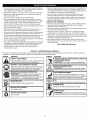
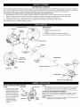
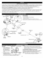
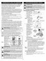
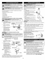

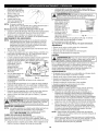


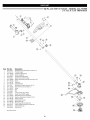


![CRRFTSMRN °] - at snowblowerguide.com](http://vs1.manualzilla.com/store/data/006202620_1-711fb90bb2c79d693479b4ac54c29ad0-150x150.png)