1
Owner's Manual
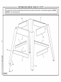
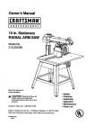
254 mm (10 in.) Stationary
RADIAL ARM SAW
Stock No.
927373
Model No.
315.273731
Save this manual for
future reference.
,A CAUTION:
Read and follow all
Safety Rules and Operating
Instructions before first use of this
product.
Customer
Help Line: 1-877-369-8665
Sold by: Sears
Canada
Inc., Toronto
M5B 2B8
Visit the Craftsman web page: www.sears.com/craftsman
972000-706
4-00
• Safety
• Features
•
•
•
•
Assem bly
Operation
Maintenance
Parts List
FULL TWO YEAR WARRANTY
ON CRAFTSMAN
TOOL
If this CRRFTSMRN Tool fails to operate within two years from the date of purchase, return it to the nearest
Sears Canada Inc. ("Sears") store and "Sears" will repair it, free of charge.
If this tool is used for rental purposes, this warranty applies for only 90 days from the date of purchase.
This warranty is in addition to any statutory warranty.
Sears Canada Inc., Toronto M5B 2B8
Your saw has many features for making cutting operations more pleasant and enjoyable. Safety, performance
and dependability have been given top priority in the design of this saw making it easy to maintain and operate.
,_
CAUTION:
Carefully read through this entire owner's manual before using your new saw. Pay close
attention to the Rules For Safe Operation, and all Safety Alert Symbols, including Danger, Warning and
Caution. If you use your saw properly and only for what it is intended, you will enjoy years of safe, reliable
service.
,_
Look for this symbol
involved.
,_
WARNING:
to point out important
safety precautions.
It means attention!!!
Your safety
is
The operation of any power tool can result in foreign objects being thrown into your eyes,
which can result in severe eye damage. Before beginning power tool operation, always wear
safety goggles or safety glasses with side shields and a full face shield when needed. We
recommend Wide Vision Safety Mask for use over eyeglasses or standard safety glasses
with side shields, available at Sears Retail Stores.
• Warranty and Introduction ...............................................................................................................................
2
• Table of Contents ..........................................................................................................................................
2-3
•
Rules For Safe Operation .............................................................................................................................
4-7
•
Electrical ........................................................................................................................................................
8-9
•
Product Specifications and Glossary ........................................................................................................
10-11
•
Unpacking and Accessories
•
Loose Parts List ........................................................................................................................................
..........................................................................................................................
• Tools Needed .................................................................................................................................................
11
12-14
15
•
Features ....................................................................................................................................................
16-19
•
Assembly ...................................................................................................................................................
20-34
Assembling Leg Stand ...................................................................................................................................
20
Mounting Saw to Leg Stand ...........................................................................................................................
21
Attaching Elevating Handwheel .....................................................................................................................
21
CR_FI'=_HRN
° RADIALSAW 315.273731
2
Installing the Yoke Assembly .........................................................................................................................
22
Removing the Blade .......................................................................................................................................
23
Attaching Table Supports ..............................................................................................................................
23
Setting the Arm Lock Knob ............................................................................................................................
24
Setting the Yoke Clamp .................................................................................................................................
24
Setting the Bevel Lock Lever .........................................................................................................................
25
Tightening the Arm and Column ....................................................................................................................
26
Adjusting the Column Tube ......................................................................................................................
•
•
26-27
Adjusting the Carriage Bearings ....................................................................................................................
28
Leveling the Table Supports ..........................................................................................................................
29
Installing the Front Table ...............................................................................................................................
30
Leveling the Front Table ................................................................................................................................
31
Installing Rear Table, Spacer Table, Fence, and Clamps ........................................................................
31-32
Installing Blade and Blade Guard ..................................................................................................................
32
Aligning Riving Knife to Blade ........................................................................................................................
33
Installing Rip Scale Indicators ........................................................................................................................
34
Adjustments
..............................................................................................................................................
34-40
Aligning the Arm for Cross Cuts ....................................................................................................................
35
Aligning the Blade to Table at 0 ° Bevel .........................................................................................................
36
Squaring Blade to Fence ...............................................................................................................................
37
Paralleling Blade to Table ..............................................................................................................................
38
Aligning the Rip Scale Indicators ...................................................................................................................
39
Installing Control Cut Device .........................................................................................................................
40
Operation ..................................................................................................................................................
41-51
Basic Operation of the Radial Arm Saw ........................................................................................................
41
Types of Cuts .................................................................................................................................................
41
Switch and Switch Key ...................................................................................................................................
Causes of Kickback .......................................................................................................................................
42
42
Avoiding Kickback ..........................................................................................................................................
42
Cutting Aids ....................................................................................................................................................
43
Making a Cross Cut .......................................................................................................................................
44
Making a Miter Cut .........................................................................................................................................
45
Making a Bevel Cut ........................................................................................................................................
46
Making a Compound Cross Cut .....................................................................................................................
47
Rip Cut Hazards and Precautions .................................................................................................................
Setting Up a Rip Cut .................................................................................................................................
48
48-49
Making a Rip Cut ...........................................................................................................................................
49
Making Other Cuts .........................................................................................................................................
50
Cutting Long Workpieces ...............................................................................................................................
50
Non-Through Cuts .........................................................................................................................................
51
•
Maintenance
52
•
Troubleshooting
•
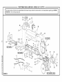
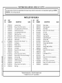
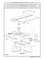
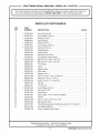
Exploded View and Repair Parts List .......................................................................................................
•
Parts Ordering / Service ....................................................................................................................
..................................................................................................................................................
........................................................................................................................................
3
53-57
58-79
back page
I:RRFI'._HRN
° RADIALSAW315.273731
The purpose of safety symbols is to attract your attention to possible dangers. The safety symbols, and
the explanations with them, deserve your careful attention and understanding. The safety warnings do
not by themselves eliminate any danger. The instructions or warnings they give are not substitutes for
proper accident prevention measures.
SYMBOL
MEANING
A
SAFETY ALERT SYMBOL
Indicates danger, warning or caution. May be used in conjunction with other symbols or
pictographs.
A
DANGER: Failure to obey a safety warning will result in serious injury to yourself or to others.
Always follow the safety precautions to reduce the risk of fire, electric shock and personal injury.
A
WARNING:
Failure to obey a safety warning can result in serious injury to yourself or to others.
Always follow the safety precautions to reduce the risk of fire, electric shock and personal injury.
A
CAUTION:
Failure to obey a safety warning may result in property damage or personal injury to
yourself or to others. Always follow the safety precautions to reduce the risk of fire, electric shock
and personal injury.
Note:
Advises you of information or instructions vital to the operation or maintenance of the equipment.
IMPORTANT
WARNING:
Do not attempt to operate this tool
until you have read thoroughly and understand
completely all instructions, safety rules, etc.
contained in this manual. Failure to comply can
result in accidents involving fire, electric shock,
or serious personal injury. Save owner's manual
and review frequently for continuing safe
operation, and instructing others who may use
this tool.
Servicing requires extreme care and knowledge of the
system and should be performed only by a qualified
service technician. For service we suggest you contact
your nearest Sears repair center. Always use original
factory replacement parts when servicing.
If you have questions about terms in the following
rules, refer to the Glossary of Terms for Woodworking
or the Features section.
READ ALL INSTRUCTIONS
•
•
•
KNOW YOUR POWER TOOL. Read the owner's
manual carefully. Learn the saw's applications and
limitations as well as the specific potential hazards
related to this tool.
DO NOT USE IN DANGEROUS
•
ENVIRONMENT.
DRESS PROPERLY. Do not wear loose clothing,
gloves, neckties, rings, bracelets, or other jewelry.
They can get caught and draw you into moving
parts. Nonslip footwear is recommended. Also
wear protective hair covering to contain long hair.
KEEP CHILDREN AND VISITORS AWAY. All
visitors should wear safety glasses and be kept a
safe distance from work area. Do not let visitors
•
KEEP WORK AREA CLEAN. Cluttered work
areas and work benches invite accidents. DO NOT
leave tools or pieces of wood on the saw while it is
in operation. Keep floors clean and free of sawdust.
•
MAINTAIN TOOLS WITH CARE. Keep tools sharp
and clean for better and safer performance. Follow
instructions for lubricating and changing accessories.
CRRFTSHRN° RADIALSAW 315.273731
ALWAYS WEAR SAFETY GLASSES WITH SIDE
SHIELDS. Everyday eyeglasses have only impactresistant lenses; they are NOT safety glasses.
contact the tool or extension cord while operating.
•
USE THE RIGHT TOOL FOR THE JOB. Do not
force the tool or attachment to do a job it was not
designed for. Use it only the way it was intended.
Do not use power tools near gasoline or other
flammable liquids, in damp or wet locations, or
expose them to rain. Keep the work area well lit.
•
MAKE WORKSHOP CHILD-PROOF with padlocks
and master switches or by removing switch keys.
4
•
NEVER STAND ON TOOL. Serious injury could
occur if the tool is tipped or if the blade is unintentionally contacted.
•
DO NOT OVERREACH.
balance at all times.
•
SECURE WORK. Use clamps or a vise to hold
work when practical. It's safer than using your
hand and frees both hands to operate the tool.
Keep proper footing and
•
USE THE PROPER EXTENSION CORD. Make
sure your extension cord is in good condition. Use
only a cord heavy enough to carry the current your
product will draw. An undersized cord will cause a
drop in line voltage resulting in loss of power and
overheating. A wire gage size (A.W.G.) of at least
14 is recommended for an extension cord 25 feet
or less in length. If in doubt, use the next heavier
gage. The smaller the gage number, the heavier
the cord.
•
AVOID ACCIDENTAL STARTING.
is off when plugging in the tool.
•
REMOVE WRENCHES AND ADJUSTING KEYS.
Get in the habit of checking - before turning on the
tool - that hex keys and adjusting wrenches are
removed from tool.
•
•
•
•
DO NOT FORCE THE TOOL. It will do the job
better and more safely at the rate for which it was
designed.
BEFORE MOUNTING, DISCONNECTING OR
REMOUNTING THE MOTOR; unplug the saw and
remove the switch key.
4_
CHECK DAMAGED PARTS. Before using the tool
again, check any damaged parts, including guards,
for proper operation and performance. Check
alignment of moving parts, binding of moving parts,
breakage of parts, saw stability, mounting, and any
other conditions that may affect its operation. A
damaged part must be properly repaired or replaced by a qualified service technician at a Sears
repair center to avoid risk of personal injury.
USE ONLY CORRECT BLADES. Use the right
blade style for the material and the type of cut.
Use only blades marked for at least 5,000 rpm and
10 in. or smaller, with a 5/8 in. arbor hole.
KEEP GUARDS IN PLACE and in good working
order. This includes the blade guard, the riving
knife, and the anti-kickback pawls.
CHECK DIRECTION OF FEED. When ripping,
feed work into a blade or cutter against the direction of rotation of the blade or cutter.
•
NEVER LEAVE TOOL RUNNING UNATTENDED.
TURN THE POWER OFF. Do not leave the tool
until it comes to a complete stop.
•
DISCONNECT ALL TOOLS. When not in use,
before servicing, or when changing attachments,
blades, bits, cutters, etc., all tools should be
disconnected from the power supply.
Be sure switch
•
•
•
USE RECOMMENDED ACCESSORIES. Using
improper accessories may risk injury. Consult the
Accessories section for recommended accessories.
WARNING:
When servicing, use only identical
Craftsman replacement parts. Use of any other
parts may create a hazard or damage product.
•
NEVER USE THIS TOOL IN AN EXPLOSIVE
ATMOSPHERE. Normal sparking of the motor
could ignite fumes.
•
MAKE SURE THE WORK AREA HAS AMPLE
LIGHTING to see the work and that no obstructions will interfere with safe operation BEFORE
performing any work using this tool.
•
DO NOT USE TOOL IF SWITCH DOES NOT
TURN IT ON AND OFF. Have defective switches
replaced by a qualified service technician at a
Sears repair center.
•
GUARD AGAINST ELECTRICAL SHOCK by
preventing body contact with grounded surfaces
such as pipes, radiators, ranges, refrigerator
enclosures.
•
GROUND ALL TOOLS. See Electrical page.
•
WEAR A DUST MASK to keep from inhaling fine
particles. Use wood dust collection systems
whenever possible.
•
PROTECT YOUR HEARING. Wear hearing
protection during extended periods of operation.
•
DO NOT OPERATE THIS TOOL WHILE UNDER
THE INFLUENCE OF DRUGS, ALCOHOL, OR
ANY MEDICATION.
STAY ALERT AND EXERCISE CONTROL. Watch
what you are doing and use common sense. Do
not operate tool when you are tired. Do not
rush.
USE ONLY SEARS REPLACEMENT PARTS. All
repairs, whether electrical or mechanical, should
be made by a qualified service technician at a
Sears repair center.
AVOID AWKWARD OPERATIONS AND HAND
POSITIONS where a sudden slip could cause your
hand to move into the blade. ALWAYS make sure
you have good balance.
5
CRRFI'._HRN
_ RADIALSAW315.273731
•
•
•
•
GUARD AGAINST KICKBACK. Kickback can
occur when the blade stalls, driving the work piece
back toward the operator. It can cause your hand
•
to contact the blade, resulting in serious personal
injury.
Stay outofthe bladepathand turnswitch
offimmediatelyifblade bindsorstalls.
• ALWAYS PUSH THE WORKPIECE
never pull it toward the saw.
USE A SUPPORT FOR THE SIDES AND BACK
OF THE SAW TABLE when sawing wide or long
workpieces to minimize the risk of blade pinching
and kickback. Use a sturdy "outrigger" support to
prevent tipping if a table extension more than 24
inches long is attached to the saw.
CUT ONLY WOOD, PLASTIC OR WOOD-LIKE
MATERIALS. Do not cut metal.
•
ALWAYS TURN OFF SAW before disconnecting
it, to avoid accidental starting when reconnecting
to the power supply. NEVER leave the saw
unattended while connected to a power source.
•
BEFORE CHANGING THE SETUP, REMOVING
COVERS, GUARDS, OR BLADE; unplug the saw
and remove the switch key.
•
KEEP TOOL DRY, CLEAN, AND FREE FROM
OIL AND GREASE. Always use a clean cloth
when cleaning. Never use brake fluids, gasoline,
petroleum-based products, or any solvents to
clean tool.
• BEFORE MAKING A CUT, be sure all adjustments
are secure.
NEVER cut more than one piece at a time. DO
NOT STACK more than one workpiece on the saw
table at a time.
•
DO NOT REMOVE THE SAW'S BLADE GUARD.
Never operate the saw with the blade guard
removed. Make sure all guards are operating
properly before each use.
KEEP BLADES CLEAN, SHARP AND WITH
SUFFICIENT SET. Sharp blades minimize stalling
and kickback. Keep blades free of rust, grease,
and pitch.
,_k
USE THE RIP FENCE. Always use a fence or
straight edge guide when ripping.
• BE SURE THE BLADE PATH IS FREE OF
NAILS. Inspect for and remove all nails from
lumber before cutting.
•
BE SURE THE BLADE CLEARS THE WORKPIECE. Never start the saw with the blade touching
the stock.
•
KEEP HANDS AWAY FROM CUTTING AREA.
Do not reach underneath work or in blade cutting
path with your hands and fingers for any reason.
Always turn the power off when cut is complete.
•
USE A PUSHBLOCK OR PUSHSTICK in rip mode
for workpieces so small that your fingers go under
the blade guard. NEVER TOUCH BLADE or other
moving parts during use, for any reason.
WARNING:
Blade coasts after being turned off.
USE ONLY OUTDOOR EXTENSION CORDS.
Use only extension cords with the marking "Acceptable for use with outdoor appliances; store
indoors while not in use." Use extension cords with
an electrical rating not less than the saw's rating.
Always disconnect the extension cord from the
outlet before disconnecting the product from the
extension cord.
• NEVER PERFORM ANY OPERATION FREEHAND. Always place the workpiece to be cut on
the saw table and position it firmly against the
fence as a backstop.
•
INSPECT TOOL CORDS AND EXTENSION
CORDS PERIODICALLY and, if damaged, have
repaired by a qualified service technician at a
Sears repair center. Stay constantly aware of cord
location and keep it well away from the moving
blade.
• DO NOT ABUSE CORD. Never yank the cord to
disconnect it from receptacle. Keep the cord from
heat, oil, and sharp edges.
•
SAVE THESE INSTRUCTIONS. Refer to them
frequently and use to instruct other users. If you
loan someone this tool, loan them these instructions also.
SAVE THESE INSTRUCTIONS
CRRF:I'$HRN° RADIALSAW 315.273731
when ripping;
DO NOT FEED THE MATERIAL TOO QUICKLY.
Do not force the workpiece against the blade.
DO NOT USE A PERSON AS A SUBSTITUTE
FOR A TABLE if additional support is needed. Use
a support the same height as the table.
•
ALLOW THE MOTOR TO COME UP TO FULL
SPEED before starting a cut to avoid blade binding
or stalling.
6
•
SECURE THE SAW. Firmly bolt the saw to the leg
stand to keep the saw from tipping, walking, or
sliding.
•
DO NOT SET UP WORK WITH THE BLADE
SPINNING. Keep the saw power off until you are
ready to use it.
•
•
•
•
•
the saw to allow enough room on all sides so
neither the operator nor a visitor stands in line with
the sawblade.
•
NEVER LOWER AN UNLOCKED REVOLVING
CUTTING TOOL. A(ways lock the carriage lock
knob before lowering the blade.
AVOID HEELING by adjusting the saw blade so it
exactly parallels the fence during ripping operations.
AVOID GRABBING in rip mode by keeping the
saw blade correctly adjusted and by feeding the
work from the infeed side (opposite the antikickback pawls).
SHUT OFF THE POWER TO FREE A JAMMED
GUARD. Press the switch off before putting your
hands near the blade. Wait for the blade to stop,
then free the guard.
•
LOCK THE SAW BEFORE MOVING IT. Secure
the radial arm with the arm lock knob. Secure the
carriage with the carriage lock knob.
AVOID PINCHING by using a riving knife and
sharp saw blade. Keep the work positioned firmly
against the fence.
•
USE IN-RIP WHENEVER POSSIBLE by positioning the work so the blade is between (inside) the
column and the motor.
•
NEVER ADJUST GUARD, PAWLS, OR BLADE
WITHOUT DISCONNECTING THE POWER.
POSITION THE WORKPIECE WITH THE FINISHED SIDE DOWN. If the anti-kickback pawls
catch the wood to stop kickback, they could mar
the top surface or cause splintering.
POSITION THE WORKPIECE SO NO ONE MUST
STAND IN LINE WITH THE BLADE. If kickback or
climb occurs, a helper, operator, or observer in the
sawblade path could be seriously injured.
•
POSITION THE CUT SO THE WASTE PART
FALLS OFF. Never use a length stop on the free
end of the workpiece. Never apply force to the free
end or hold it while the sawblade is rotating.
•
KEEP THE SAW BLADE PATH CLEAR. Position
RIP ONLY WORKPIECES LONGER THAN THE
BLADE'S DIAMETER. Never rip a piece of wood
that is shorter than the diameter of the blade.
•
,_
BEFORE CUTTING, position and tighten the blade
guard and anti-kickback pawls. Test the pawls to
make sure they would stop kickback if it started.
Keep the points sharp.
Always turn off the switch and unplug the cord
before freeing a jammed blade, tightening a loose
blade, or repositioning the guard or pawls.
,_L
NEVER CUT MORE THAN ONE PIECE OF
WOOD AT A TIME. The feed will be uneven and
could cause the blade to pick up one or more
pieces and cause serious injury.
WARNING:
In a rip cut, holding the cut-off edge
behind the blade can cause the cut edges to
pinch, risking kickback. It could cause the blade
to climb over the front edge of the wood and
contact your hand.
TURN OFF SAW IF A STRANGE NOISE OR
HEAVY VIBRATION OCCURS. Immediately turn
off the saw, locate the source, and correct the
problem before using the saw further.
POSITION THE CUT SO THE BLADE WILL NOT
EXTEND BEYOND THE EDGE OF THE TABLE.
BEFORE STARTING EACH CUT, check that no
play exists in the carriage. Be sure the arm, yoke
and bevel locks and clamps are tight. Verify the
blade, all handles, blade washers, and blade nuts
are secure.
•
BEFORE MAKING A CUT, test the upper and
lower blade guards for free movement up and
down. Position the nose of the guard to just clear
the workpiece.
•
AVOID KICKBACK AND POSSIBLE INJURY by
preventing heeling, grabbing, and pinching.
CAUTION:
Do not turn the motor switch on and
off rapidly. This can loosen the sawblade.
KEEP THE GUARDS IN PLACE AND THE WORK
SURFACE CLEAR DURING A CUT. Small objects
or wood slivers can ricochet from the blade into the
fence and back toward the operator. If the blade
loosens slivers, remove them with a stick, not your
hand.
IN A RIP CUT, DO NOT LET GO OF THE WORKPIECE UNTIL THE CUT IS COMPLETE. When the
workpiece is fed into the blade, push the workpiece
all the way past the blade.
7
I:RRIq'._HRH
° RADIALSAW315.273731
EXTENSION
CORDS
GROUNDING
Use only 3-wire extension cords that have 3-prong
grounding plugs and 3-pole receptacles that accept
the tool's plug. When using a power tool at a considerable distance from the power source, use an extension cord heavy enough to carry the current that the
tool will draw. An undersized extension cord will
In the event of a malfunction or breakdown, grounding
provides a path of least resistance for electric current
to reduce the risk of electric shock. This tool is
equipped with an electric cord having an equipmentgrounding conductor and a grounding plug. The plug
must be plugged into a matching outlet that is properly
installed and grounded in accordance with all local
codes and ordinances.
cause a drop in line voltage, resulting in a loss of
power and causing the motor to overheat. Use the
chart provided below to determine the minimum wire
size required in an extension cord. Only round jacketed cords listed by Underwriter's Laboratories (UL)
should be used.
Length of Extension
Cord
Do not modify the plug provided. If it will not fit the
outlet, have the proper outlet installed by a qualified
electrician. Improper connection of the equipmentgrounding conductor can result in a risk of electric
shock. The conductor with insulation having an outer
surface that is green with or without yellow stripes is
the equipment-grounding conductor. If repair or
replacement of the electric cord or plug is necessary,
do not connect the equipment-grounding conductor to
a live terminal.
Wire Size (A.W.G.)
Up to 25 feet
26-100 feet
14
12
When working with the tool outdoors, use an extension cord that is designed for outside use. This is
indicated by the letters WA on the cord's jacket.
Check with a qualified electrician or service personnel
if the grounding instructions are not completely
understood, or if in doubt as to whether the tool is
properly grounded.
Before using an extension cord, inspect it for loose or
exposed wires and cut or worn insulation.
,_
CAUTION:
Keep the cord away from the cutting
area and position the cord so that it will not be
caught on lumber, tools, or other objects during
cutting operations.
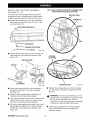
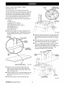
ELECTRICAL
Repair or replace a damaged or worn cord immediately.
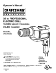
This tool is intended for use on a circuit that has an
outlet like the one shown in Figure 1. It also has a
grounding pin like the one shown.
CONNECTION
Your Sears Craftsman Radial Arm Saw is powered by
a precision built electric motor. It should be connected
to a power supply that is 120 volts, 60 Hz, AC only
(normal household current). It should be connected
to a 240 volt power supply only if it has been reset
according to the instructions
in this manual. The
motor has been set at the factory for 120 volts; if it is
reconnected to operate at 240 volts, the main power
cord plug and any receptacle must be replaced with
devices rated for 240 volts. This tool will not operate
on direct current (DC). A substantial voltage drop will
cause a loss of power and the motor will overheat. If
the saw does not operate when plugged into an outlet,
double check the power supply.
GROUNDING
PIN
COVEROFGROUNDED
OUTLETBOX
SPEED AND WIRING
The no-load speed of your saw is approximately 3,600
rpm. This speed is not constant. For voltage, the
wiring in a shop is as important as the motor's horsepower rating. A line intended only for lights cannot
properly carry a power tool motor. Wire that is heavy
enough for a short distance will be too light for a
greater distance. A line that can support one power
tool may not be able to support two or three tools.
CRRFTSHRN° RADIALSAW 315.273731
INSTRUCTIONS
8
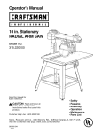
Fig. 1
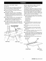
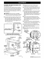
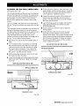
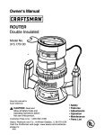
CHANGING
LIFT MOTORCOVERTO EXPOSESWITCH
VOLTAGE
See Figures 2-4.
Your radial saw has been set up at the factory to
operate efficiently on a 120V AC single voltage circuit.
However, if heavy duty operation is required, the
circuits are overloaded, or the circuit is low voltage,
have a qualified electrician change the voltage on the
main power system to a 240V AC voltage circuit.
_
WARNING:
The control cut device is set up for
a 120V AC single voltage circuit. Do not modify
the control cut cord. Identify the control cut
cord and tie it back out of the way.
•
Correctly identify the control cut cord, unplug it,
and set it aside.
•
Unplug the main power cord.
•
Remove the blade following the procedure in the
Assembly section.
•
Remove the pan head screw above the blade
arbor on the motor cover. Lift motor cover to
expose switch. See Figure 2.
•
•
O
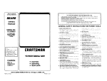
SLIDE AS SHOWNFORSINGLEVOLTAGECIRCUITS
SWITCHSHOWNIN 110-120VOLTPOSITION
Fig. 3
LIFT MOTORCOVERTO EXPOSESWITCH
Use a small screwdriver to slide the dual voltage
switch to the 240V position. See Figures 3 and 4.
Reinstall motor cover.
•
Replace the 120V plug on the main cord with a UL
listed 240V, 15 amp, 3-prong plug.
•
Follow the instructions provided with the UL listed
plug.
•
Plug the cord into a 240V, 15 amp, 3-blade receptacle. Make sure the receptacle is connected to a
240V AC power supply through a 240V branch
circuit that has a 15 amp fuse or circuit breaker.
Note: No adapter is available for this type of plug or
receptacle.
MOTORCOVER
PAN HEADSCREW
SLIDEAS SHOWNFOR DUALVOLTAGECIRCUITS
SWITCHSHOWNIN 220-240VOLT POSITION
Fig. 4
/
BLADEARBOR
Fig. 2
CRRI:I'._HRN
' RADIALSAW315.273731
Blade Arbor
Blade Diameter
16 mm (5/8 in.)
16 in.
Maximum In-Rip
254 mm (10 in.)
Depth of Cut at 90 °
3 in.
0 ° _ 90 °
Depth of Cut at 45 °
2.25 in.
Blade Bevel Angle
Radial Arm Swing Range
Cutting Capacity-
Table Size
50 ° left - 90 ° right
Blade Height Adjust
5.35 in.
Table Height
Carriage Travel
17.25 in.
Rating
Cutting Capacity - Maximum Cross Cut
15.50 in.
Input
Cutting Capacity - Maximum Out-Rip
26 in.
No Load Speed
40 x 27.75 x 1 in.
914 mm (36 in.)
120V/240V 60 Hz -AC only
13.0/6.5 Amperes
3,600 RPM
Bevel Cut
Infeed
A cut made across a workpiece with the blade at any
angle other than 90 ° to the table surface.
The side of the blade where the blade teeth point up,
opposite the anti-kickback pawls.
Chamfer
In-Rip
A type of rip cut in which the blade is between the
column and the motor.
A cut removing a wedge from a block so the end (or
part of it) is angled rather than at 90 degrees.
Climb
A hazard in which the blade "climbs" over and out of
Kerr
The space left by the removal of material in a cut or
the slot produced by the blade in a non-through cut.
the workpiece, pulling the stock out of the operator's
hands or running across the workpiece.
Kickback
Compound Cut
A cross cut with both a miter angle and a bevel angle.
A hazard that can occur when blade binds or stalls,
throwing workpiece back toward operator.
Cross Cut
Leading End
The end of the workpiece pushed into the cutting tool
first.
A cutting operation with the blade parallel to the
carriage arm and the blade teeth pointing down. It can
be across or with the grain, normally across the grain
or width of the workpiece.
Miter Cut
A vertical cut made at any angle other than 0 ° across
the workpiece.
Dado Cut
A non-through cut that leaves a square notch or
trough; requires a special blade.
Molding
A shaping cut that gives a varied shape to the
workpiece and requires a special blade.
Featherboard
A device to help guide workpieces during rip cuts.
Out-Rip
A type of rip cut in which the motor is between the
blade and the column. (The blade is "outside" the
motor).
Fence
A piece of wood used as a edge guide for the
workpiece. Located perpendicular to the carriage arm.
Can be placed at different distances from the rear
table edge in combination with the other table pieces
and is secured with table clamps.
Pushstick
A device used to feed the workpiece through the saw
blade during cutting operations. It helps keep the
operator's hands well away from the blade.
Freehand
Dangerous practice of making a cut without using a
fence.
Rabbet
Gum
A type of cut that gives a notch in the edge of a
workpiece.
A sticky, sap-based residue from wood products.
Resaw
Heel
Alignment of the blade to the fence.
A cutting operation to reduce the thickness of the
workpiece to make thinner pieces.
CRRFT=_HRN
° RADIALSAW 315.273731
10
Resin
A sticky, sap-based substance.
Throw-Back
Saw throwing back a workpiece similar to kickback.
Rip Cut
In a radial saw, a cut made with the blade parallel to
the fence and perpendicular to the arm. Can be
across or with the grain. The teeth point up at the
point of contact with the wood.
Through Sawing
Any cutting operation where the blade extends
completely through the workpiece.
Trailing End
The workpiece end last cut by the blade in a rip cut.
Sawblade Path
The area directly in line with the blade -- over, under,
behind, or in front of it. Also, the workpiece area which
will be or has been cut by the blade.
Workpiece
The item on which the cutting operation is being done.
The surfaces of a workpiece are commonly referred to
as faces, ends, and edges.
Set
The distance that the tip of the saw blade tooth is off
set from the face of the blade.
Worktable
The surface on which the workpiece rests while
performing a cutting operation.
,_
•
Carefully remove all parts from the carton and
place the saw on a level work surface. Separate
and check against the list of loose parts.
•
Do not discard the packing materials until you have
carefully inspected the saw, identified all parts, and
satisfactorily operated your new saw.
_
WARNING:
To prevent accidental starting that
could cause possible serious personal injury,
assemble all parts to your saw before connecting
it to power supply. The saw should never be
connected to the power supply when you are
assembling parts, making adjustments, installing
or removing blades, or when not in use.
Note: If any parts are damaged or missing, do not
attempt to plug in the power cord and turn the
switch on until the damaged or missing parts
are obtained and are installed correctly.
WARNING:
If any parts are missing, do not
operate this tool until the missing parts are
replaced. Failure to do so could result in possible
serious personal injury.
FOR A COM PLETE SELECTION OF ACCESSORIES
FORTHIS AND OTHER CRAFTSMAN POWER AND
BENCH TOOLS, VISIT YOUR NEAREST SEARS
RETAIL STORE.
11
CRRR'._MRN
° RADIALSAW315.273731
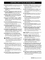
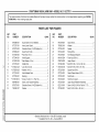
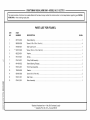
Checkall loosepartsfromthe boxwiththelist below.Usetheinstructions
onthefollowingpagesto assemble.
Allfastenersareshownactualsize.
1. SawAssembly
....................................................
1
SAWASSEMBLYSHOWNAS PACKED
Fig. 5
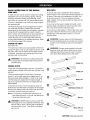
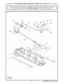
.
Elevating Handwheel
A. Handwheel .....................................................
Blade Wrench .....................................................
2
1
B. Screw (10-24 x 5/8 in. Soc. Hd.) .................... 1
C. Star Washer ...................................................
1
4.
Hex Key
A. 3/16 in. Hex Key .............................................
1
B. 1/4 in. Hex Key ...............................................
1
A
C
Fig. 6A
CRR_T=_MRN
_RADIALSAW315.273731
12
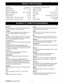
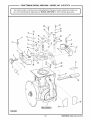
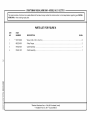
Check all loose parts from the box with the list below. Use the instructions on the following pages to assemble.
All fasteners are shown actual size.
5.
9.
Saw Base To Leg Stand Assembly
A. Saw Assembly (not shown) ...........................
Fence ..................................................................
1
1
B. Leg Stand Assembly (not shown) .................. 1
C. Hex bolt (5/16-18 x 5/8 in. Hex Head) ........... 4
D. Washer (5/16 in.) ...........................................
8
E. Lock washer (5/16 in.) ...................................
4
F. Hex Nut (5/16-18) ...........................................
4
10. Leveling Hardware for Front Table
C
.
D
E
F
Hardware for Front Table
A. Front table ......................................................
1
B. Screw (1/4-20 x 1 in.) .....................................
4
C. Washer (1/4 in.) .............................................
4
D. Lock washer (1/4 in.) .....................................
4
E. Hex nut (1/4-20) .............................................
4
A. Screw (1/4-20 x 1-3/4 in.) ..............................
B. Washer ...........................................................
1
1
C. U-clip ..............................................................
D. Setscrew ........................................................
1
1
E. Tee nut ...........................................................
1
@
A
B
®H
C
D
E
11. Scale Indicator
B
7.
C
D
Rear Table ..........................................................
A. Screw .............................................................
4
B. Speed Nut ......................................................
C. Indicator .........................................................
2
2
D. Switch Key .....................................................
2
E
1
A
C
o J
8.
Spacer Table ......................................................
1
Fig. 6B
13
rRRFTSMRN
_RADIALSAW315.273731
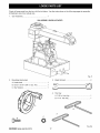
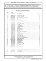
Checkallloosepartsfromthe boxwiththelist below.Usetheinstructions
onthefollowingpagesto assemble.
Allfastenersareshownactualsize.
12.TableSupport
A.TableSupportRails.......................................
2
B.Squareheadbolt(5/16-18x 3/4in.)..............4
C. Flatwasher(5/16in.).....................................
4
D.Lockwasher(5/16in.) ...................................
4
E.Hexnut(5/16-18)...........................................
4
15. Leg Stand ...........................................................
1
A. Leg .................................................................
4
B. Long bottom brace .........................................
2
C. Long top brace ...............................................
2
D. Short bottom brace ........................................
2
E. Short top brace ..............................................
2
F. Foot ................................................................
4
G. Screw (1/4-20 x 5/8 in.) ...............................
40
H. Star washer ..................................................
40
I. Hex nut (1/4-20) ............................................
40
J. Hex nut (3/8-16) ..............................................
8
A
@ ©©
B
C
D
o
E
13. Table Clamp .......................................................
2
A. Thumb screw (2) ............................................
2
B. Square nut .....................................................
2
C. Table clamp bracket ......................................
2
D. Cup washer ....................................................
2
o
o
o
o
o
o
E
D
B
C
14. Owner's Manual (not shown) .............................
1
G
F
m
o@@,
H
I
J
Fig. 6C
CRRi:'rsMRN_RADIALSAW315.273731
14
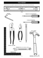
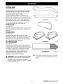
The following tools are needed for assembly and alignment. They are not included with this saw.
LEVEL
HEX KEYS:
5/32in. AND1/8in.
MEDIUMFLAT BLADE SCREWDRIVER
#2 PHILLIPSSCREWDRIVER
PENCIL
SMALL HAMMER
PLIERS
CHANNELLOCKPLIERS
WRENCHES:7/16 in., 1/2in., 9/16 in., 15/16in.
+_
FRAMINGSQUARE
15
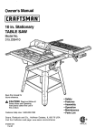
Fig. 7
rRFtFTSMAN° RADIALSAW315.273731
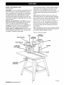
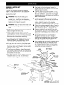
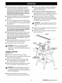
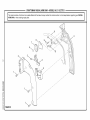
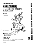
KNOW YOUR
RADIAL
SAW
Control functions include 1 ) column height (elevating
handwheel), 2) arm angle (arm lock knob), 3) yoke
movement on arm (*carriage lock knob) 4) yoke
rotation (*yoke pivot latch and *yoke lock handle), and
5) blade bevel (*bevel index lever and *bevel lock
knob).
See Figure 8A.
OVERVIEW -The main operating components include
the column, the arm, and the yoke assembly (yoke,
motor, and blade), and their operation is summarized
in the paragraph below. Safety features and control
functions are given also. Spending a few minutes
reviewing the illustrations and features list below and
on the following pages to locate these items will make
assembly easier.
Safety features include the control cut device, the
removable switch key, and the blade guard assembly.
Never operate the saw without ensuring these safety
features are in place and functioning correctly.
On a radial saw, "cross cut" means a cut parallel to
the arm, and a "rip cut" is perpendicular to the arm.
There are several ways to make cuts, depending on
the size and material of the workpiece and the end
result desired.
METHOD OF OPERATION: The column at the back
of the saw supports the radial arm. The arm can be
raised or lowered to change the blade height or
swiveled left and right for a miter cut. A yoke fits into
a carriage on the arm, which can travel back and
forward. The yoke supports the yoke assembly
(motor, blade, and blade guard) and can be pivoted
so the blade faces right, front, or left. The motor can
be rotated to change the blade angle.
Before attempting to use your saw, familiarize yourself
with all operating features and safety requirements of
your Sears Craftsman Radial Arm Saw.
*Shown on following pages
CONTROL
CUTHOUSlNG
YOKE
ARM LOCKKNOB
CARRIAGE
AND COVER
SWITCHAND KEY
COLUMN
BLADE AND
BLADEGUARD
MOTOR
ELEVATING
HANDWHEEL
Fig. 8A
CRR_T=_MRN
_RADIALSAW315.273731
16
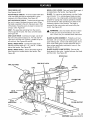
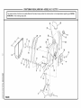
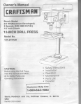
FEATURES
LIST
BEVEL LOCK LEVER - Sets and locks blade angle. It
is located below the handle. See Figure 8B.
See Figures 8A-8D.
BLADE - For maximum performance, use the Craftsman 40-tooth, 10 in. carbide-tipped blade provided
with your saw. It is a high-quality combination blade
suitable for ripping and crosscut operations. Blades
recommended for other operations are listed in the
Accessory section of this manual. The blade is
powered by the main motor and turned off by the
switch. See Figure 8D.
ADJUSTABLE TABLES - A narrow spacer table and
wider rear table that can be repositioned or even
replaced with different tables. See Figure 8C.
ANTI-KICKBACK
PAWLS - Toothed pawls that snag
the work in case of kickback during rip cuts. (When
the blade is parallel to the arm, the pawls are in front
of the blade.) Keep the pawls in place to reduce risk
of injury. See Figure 8D.
ARM - The assembly extending from the column,
which supports the yoke, the motor, and the blade.
See Figure 8A.
_k
ARM LOCK KNOB - Controls arm angle. Use to set
the arm to the positive stops at 0 °, 45 ° left, and 45 °
right and to lock the arm in place. Located on top of
arm at front. See Figures 8A and 8B.
WARNING:
Use only blades rated for at least
5,000 rpm and recommended for use on this
saw. Check with your nearest Sears retail store.
BEVEL INDEX KNOB - Controls the blade angle
between positive stops at 0°, 45 °, and 90 °. Located
behind the handle. See Figure 8B.
BLADE GUARD ASSEMBLY - Protective unit over
the blade, with a riving knife, anti-kickback pawls, an
upper blade guard, a lower outer blade guard, and a
lower inner blade guard. Always keep each item in
place unless specifically instructed to move it. See
Figures 8A and 8D.
BEVEL INDEX SCALE - Shows the blade angle for
bevel cuts and is located behind the handle. See
Figure 8B.
BLADE GUARD CLAMP SCREW - Secures the
blade guard to the motor. Located between the blade
and the motor. See Figure 8D.
MITERSCALE
YOKEPIVOTLATCH
ARMLOCKKNOB
RIP
SCALE(S)
YOKE
COLUMNTUBE
YOKE
LOCKHANDLE
BEVEL
INDEXKNOB
BEVEL
INDEXSCALE
COLUMNSUPPORT
o
BEVEL
o
LOCKLEVER
MOTOR
17
Fig. 8B
rRnFTSMRN° RADIALSAW315.273731
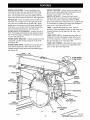
CARRIAGE - Slides along track under arm and
supports yoke. Contained in two carriage covers, one
on each side of the arm. See Figure 8C.
DUAL VOLTAGE - If needed, your main power
source may be rewired by a qualified electrician to
provide a 240V AC circuit. See the Electrical section.
CARRIAGE LOCK KNOB - Controls whether the
carriage is locked or can travel. Located on the left
side of the arm on the carriage cover. See Figure 8C.
DUST GUIDE - Directs sawdust, created from the cut
being made, in the direction you set. Located at the
rear of the upper blade guard. See Figure 8D.
COLUMN - Upright housing at the back of the saw,
consisting of a column support and a column tube.
The column tube can be raised or lowered with the
elevating handwheel at the front of the saw. See
Figures 8A and 8B.
ELEVATING HANDWHEEL - The handwheel below
the worktable (in front) that changes the height of the
arm and the blade. See Figure 8C.
CONTROL CUT DEVICE - Limits carriage speed to
prevent climb, using a cable from the carriage to the
column. Has a separate motor on left side, which is
activated by the switch trigger in the handle. The
cable returns the carriage to the column when the
motor is not activated. Speed is adjusted with a
thumbwheel on the handle. It runs on a separate
120V AC single voltage circuit. See Figure 8C.
FRONT TABLE - Fixed portion of the worktable that
supports the work. See Figure 8C.
,_
FENCE - Removable guide for work, which extends
across width of table. See Figure 8C.
HANDLE - Used to pull the yoke assembly. Mounted
on the yoke to the right of the blade. See Figure 8C.
HOLD DOWN - A metal guard to control workpiece
climb during rip cuts. When blade parallels arm, hold
down is over the back of the blade. See Figure 8D.
HOLD DOWN KNOB - Controls placement of the hold
down and locks it in place. See Figure 8D.
WARNING:
When connecting only one of the
cords, squeeze the switch trigger in the handle. If
the main motor cord alone is connected, the
switch trigger in the handle will not operate the
control cut device. The carriage cannot be
advanced without power to the control cut device.
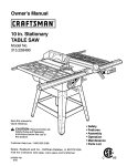
TRACK
MITER SCALE - Shows the miter angle setting of the
arm. See Figure 8B.
CARRIAGE
LOCK KNOB
CARRIAGE
AND COVER
CONTROL
CUTMOTOR
SWITCH
AND KEY
CONTROL
CUTCABLE
CONTROLCUT
THUMBWHEEL
REAR
TABLE
FRONTTABLE
HANDLE
SPACER
TABLE
FEN_
ELEVATING
HANDWHEEL
Fig. 8C
CRR_T=_MRN
_RADIALSAW315.273731
18
MOTOR (13/6.5 AMP) - Powers the blade and is
controlled by the switch and key at the front of the
arm. The powerful induction motor has a capacitor
start. It is mounted in the yoke and rotated with the
bevel index knob and bevel lock lever. See Figure 8B.
SWITCH TRIGGER - Used to power the control cut
device to allow yoke assembly to be pulled forward.
Mounted in the handle. See Figure 8D.
SWITCH WITH KEY - Powers the blade motor.
Placed on the front of the arm for easy access. To
lock the switch once it has been pressed to OFF,
remove the yellow key. Place the key in a location that
is inaccessible to children and others not qualified to
use the tool. See Figures 8A and 8C.
RIP SCALES - Show the distance from the fence to
the blade. (In-rip scales are on the right side of the
arm, and out-rip scales are on the left side.) Upper
scales show the distance with the fence beside the
front table. Lower scales show the distance with the
fence in farthest back position. See Figure 8B.
YOKE - Supports the blade and motor. Can be
pivoted to index the blade between rip and cross cuts.
Located between the carriage and the motor. See
Figure 8B.
RIVING KNIFE OR SPREADER - Located directly in
front of the blade and beside the anti-kickback pawls,
the riving knife keeps cut edges from binding during
rip cuts. See Figure 8D.
YOKE PIVOT LATCH - Indexes the yoke (after it is
released) to position the blade to face right (out-rip
cut), front (cross cut), or left (in-rip cut). Located on
the right carriage cover. See Figure 8B.
RIVING KNIFE BRACKET - Allows adjustment of the
riving knife. Located midway along the riving knife.
See Figure 8D.
YOKE LOCK HANDLE - Releases the yoke to allow
indexing for rip cut or cross cut. Located below the
yoke, on the right. See Figure 8B.
RIVING KNIFE KNOB - Adjusts the riving knife and
locks both the pawls and the riving knife in place.
Located toward the top and front of the blade guard.
See Figure 8D.
BLADEGUARD
CLAMPSCREW
DUSTGUIDE
HOLD DOWN
SWITCH
;ER
HOLD
DOWNKNOB
RIVING
KNIFEKNOB
RIVINGKNIFE
UPPER
BLADE GUARD
RIVING
KNIFE BRACKET
LOWER
BLADEGUARD
o
ANTI-KICKBACK
PAWLS
o
BLADE
_Fig.
19
8D
rRRFTSMRN
_RADIALSAW315,273731
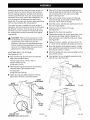
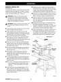
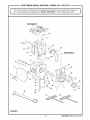
Assemblyis bestdonein theareawherethesawwill
beused.Whenyouremovethesawandhardware
fromthepackingmaterials,
carefullychecktheitems
withtheLoosePartslist.If youareunsureaboutthe
description
of anypart,refertotheirillustrations.
For
yourconvenience,
allfastenershavebeendrawn
actualsize.If anypartsaremissing,delayassembling
untilyouhaveobtainedthe missingpart(s).
Yourradialarmsawis capableofa widevarietyof
operations,
andthusrequiresa numberof initialsetup
adjustments.
However,oncethesawis setup,you
cancheckyoursawinabouttenminutesandcorrect
anymisalignment
withtheprocedures
in theAdjust-
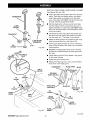
•
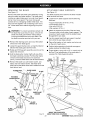
Place a 3/8-16 hex nut on each leveling foot and
insert leveling feet into the bottom of the legs. Cap
with remaining 3/8-16 hex nuts but only finger
tighten. See Figure 9A.
•
Place a short upper brace inside two of the legs
(wide end of legs up) and align the three holes in
the brace with the holes in the legs.
•
Insert the screws. Add the star washers and 1/4-20
hex nuts. Finger tighten.
•
Install a short lower brace on the legs.
See Figure 9A.
•
Repeat for the other end assembly.
ment section.
•
Connect the leg sets with a long upper brace. Add
the hardware and finger tighten. Repeat for the
other side brace, then install the long lower braces.
See Figure 9B.
•
Tighten all screws, washers, and nuts with a 7/16
in. wrench and as needed a #2 phillips screwdriver.
•
Move the leg stand to the desired location. Using a
level, adjust the leveling feet by raising or lowering
the bolts with a 9/16 in. wrench.
•
When the leg stand is level, securely tighten all four
nuts with the wrench.
•
Your leg stand is now completely assembled and
ready for use. See Figure 9C.
_
CAUTION:
Perform all the procedures in both
the Assembly and Adjustments sections before
using the saw. Run a check on your saw
frequently, referring to the Adjustments section.
Failure to perform the adjustments in the initial
set up or on a frequent basis can result in poor
performance or machine damage.
ASSEMBLING
LEG
STAND
See Figures 9A - 9C.
•
Take the following hardware from the hardware
bags in the leg stand carton:
40 truss head screws (1/4-20 x 5/8 in.)
40 star washers (1/4 in.)
40 hex nuts (1/4-20)
•
LONG
UPPERBRACE
Take the following hardware from the remaining
hardware bags in the leg stand carton:
4 leveling feet
8 large hex nuts (3/8-16)
•
Obtain four legs and eight braces from the leg
stand carton. See the Loose Parts section.
SHORT
IPPERBRACE
SHORT
LOWERBRACE
LONG
LOWERBRACE
Fig. 9B
WASHER
STAR
TRUSS
HEABSCREW
HEXNUT
(1_-20)
HEXNUT
(3/8-16)
LEVELINGFOOT
CR_F;T=_MRN
° RADIALSAW315.273731
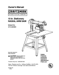
Fig. 9A
Fig. 9C
20
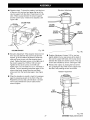
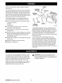
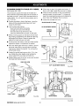
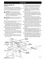
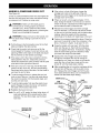
MOUNTING SAW TO LEG STAND
ATTACHING
See Figure 10.
See Figure 11.
,_
,_
•
WARNING:
Firmly bolt the saw to the leg stand
to keep the saw from tipping, walking, or sliding.
Locate the following hardware from a small hardware bag:
4
4
8
4
HANDWHEEL
WARNING:
Be sure the main power cord of
your saw is unplugged. Ignoring this precaution
could result in serious injury. Do not perform the
following steps unless the saw is unplugged.
The elevating handwheel adjusts the height of the
radial arm and the blade.
hex bolts (5/16-18 x 5/8 in.)
Iockwashers (5/16 in.)
flat washers (11/32 in.)
hex nuts (5/16-18)
•
Place the saw on top of the leg stand so the holes
in the saw base line up with the holes on top of the
leg stand braces.
•
Put a washer on a screw, and put the screw and
washer into the hole in the saw base. Cap with
another washer, then a Iockwasher and a hex nut.
Hand tighten the set.
•
ELEVATING
•
Take the handwheel, star washer, and screw
(10-24 x 5/8 in. Soc. Hd.) from the hardware bag.
•
Place the handwheel on the end of the elevating
shaft, which extends from the front of the saw base.
•
Place the star washer on the screw and thread
screw into the end of the shaft.
•
Securely tighten the screw with a 5/32 in. hex key.
•
Raise or lower the arm by turning the handwheel.
Install the other three sets and securely tighten all
four sets with a 1/2 in. wrench.
ELEVATING
SHAFT
HANDWHEEL
SCREW
SAW
BASE
t
LEG
STAND
STAR WASHER
SAW BASE
3LT
Fig. 11
FLAT
WASHER
}HER
HEXNUT
LEG STAND
Fig. 10
21
rRRFTSMRN
° RADIALSAW 315.273731
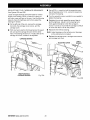
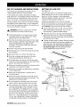
INSTALLING
THE
YOKE
ASSEMBLY
FOR CLARITY,CARRIAGECOVERSANDCARRIAGELOCK
KNOBARE NOT SHOWNIN ILLUSTRATION
See Figures 12A - 12C.
The yoke rides in the carriage below the arm and
supports the motor, the blade guard, and the blade.
Install the yoke assembly from the front of the arm.
•
ARMLOCKKNOB
BEARINGS(4)
Remove the carriage stop screw and Iockwasher
from below the front of the arm with a 1/4 in. hex
key. See Figure 12A.
CARRIAGE
ARMVIEWEDFROMBELOW
YOKE
CARRIAGESTOPSCREW
1/4 in. HEXKEY
Fig. 12A
•
Remove the arm cap screws and arm cap from the
front of the arm with a phillips screwdriver. See
Figure 12B
CARRIAGE
LOCKKNOB
ARM
ARMLOCKKNOB
ARMCAP
_
_ARM
CAPSCREWS
CARRIAGECOVER
Fig. 12B
•
Reinstall the carriage stop screw, the Iockwasher,
arm cap, and arm cap screws. Tighten all screws
securely.
Remove and discard the two motor setscrews in
the bottom of the motor. They are for shipping
purposes only.
•
Using the elevating handwheel, raise the arm 3
inches and remove the packing material.
•
Lock the arm with the arm lock knob, located on top
of the front of the arm, so the arm doesn't swing
while you are mounting the yoke assembly.
•
Pick up the yoke assembly and carefully slip it onto
the carriage track below the arm. Keep it parallel
with the arm so bearings slide in smoothly. See
Figure 12C.
I:RI_FT=_MRN
_RADIALSAW 315.273731
Fig. 12C
,t_
•
22
WARNING:
Once the yoke assembly is on the
carriage track, reinstall the arm cap, the arm cap
screws, the carriage stop screw, and the
Iockwasher. Do not risk serious injury or damage
to the saw by failing to replace these parts.
Tighten the carriage lock knob, on the carriage
cover on the left of the arm, to lock the yoke
assembly in place.
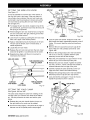
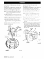
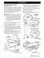
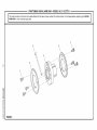
REMOVING
THE
BLADE
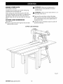
ATTACHING
TABLE
SUPPORTS
See Figure 13.
See Figure 14.
Remove the blade and blade guard assembly during
setup for safety and better access. The blade guard
includes an upper blade guard, an outer lower guard,
and an inner lower guard. The lower inner guard
consists of two overlapping slotted metal strips. The
strips are held together with a retaining screw and a
nut. Locate these items before beginning the procedure.
The table supports are a base for the three wooden
table sections and fence.
_
WARNING:
To prevent accidental contact with
the blade that could result in injury, remove the
blade and blade guard before making setups
involving the blade arbor and work stand. Use
the blade wrenches provided with your saw.
•
Locate the two table supports and the following
hardware:
4
4
4
4
square head bolts (5/16-18 x 3/4 in.)
Iockwashers (5/16 in.)
hex nuts (5/16-18)
flat washers (5/16 in.)
•
Attach the supports to the side of the saw base.
There are holes in both sides of each support. The
long side of each support (with the slotted holes)
fits against the saw base.
•
Use two square head bolts per support, inserted
from within the saw base outward.
•
Remove the retaining screw and nut at the bottom
of the lower inner blade guard.
•
Place a flat washer, a lock washer, and a hex nut
on the end of each screw.
•
Loosen the guard clamp screw, a long thumbscrew
between the blade guard and the motor.
•
Position table supports so that bolts are approximately centered in slotted holes.
•
Rotate and lift the guard assembly up and over the
blade, then remove it.
•
•
Hold the blade arbor (motor shaft) with one of the
two blade wrenches provided. Put the other blade
wrench on the blade nut and turn it clockwise
Finger tighten or snug with a 1/2 in. wrench only at
this time. Final adjustments will be made later in
Leveling The Table Supports section.
(down), since the blade arbor has left hand threads.
•
Remove the blade nut, outer blade washer, saw
blade, and inner blade washer. Set these items
aside until all the tables have been installed and the
front table is level.
THUMBSCREW _BLADE
GUARD
i:
FLAT
WASHER
SQUARE
HEADBOLT
BLADE
INNERBLADE
WASHER
BLADE
ROTATION
TABLE
SUPPORT
TABLE
SUPPORT
TO
TIGHTEN
BLADE
WRENCH(2)
BLADE
ARBOR
Fig. 13
MOUNTTABLESUPPORTS
USINGTHESEHOLE LOCATIONS
Fig. 14
23
CRtIFTSMRN
° RADIALSAW315.273731
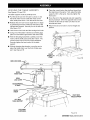
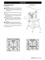
SETTING THE ARM LOCK KNOB
ARMCAP
MOTOR
See Figure 15.
It may be possible to move the arm when locked, if
the arm lock knob is too loose. If the arm does not
move freely when unlocked, the arm lock knob may
be too tight. Use this procedure to check and set the
arm lock knob by turning the arm lock wheel (under
the carriage arm).
•
To release the arm lock knob, located on top of the
arm at the front, pull the arm lock knob forward until
the spring is compressed.
•
While holding the arm lock knob forward, swing the
arm 30 ° to the left or the right, referring to the miter
scale on top of the column.
•
Apply a reasonable amount of pressure on the arm.
The arm can be forced, but if it moves easily, it
needs adjustment.
•
Locate the arm lock wheel.
to loosen.
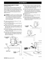
Lock the yoke lock handle. Grasp the motor with
both hands and apply reasonable pressure to see if
it slips. If it moves, reset the yoke lock handle as
follows.
•
Remove the arm cap screws and arm cap at the
front of the arm with a phillips screwdriver. See
Figure 16B.
•
Remove the carriage stop screw and Iockwasher
with a 1/4 in. hex key. Carefully slide the yoke
assembly forward and off the carriage.
•
Place the yoke assembly in a spot where it will be
secure as you work on the top of the yoke.
•
Release the yoke lock handle. Tighten the center
nut with a 15/16 in. wrench until the lock handle is
Repeat above steps until the arm movement is
minimized when locked.
ARMLOCKKNOB
ARM
TURNCOUNTERCLOCKWISETOLOOSEN
Fig. 16A
•
Release the arm lock knob and turn the lock wheel
clockwise to tighten or counterclockwise
•
YOKE
ASSEMBLY
Lock the arm in place by pushing the arm lock knob
back until it pops in the locked position.
•
•
YOKELOCK
HANDLE
centered between the two legs of the yoke.
CARRIAGE
STOPSCREW
TURNCLOCKWISE
TO TIGHTEN
ARM
LOCKWHEEL
SETTING
THE
YOKE
•
Carefully replace the yoke assembly on the carriage arm track. Slide it back about halfway.
•
Replace the carriage stop screw and Iockwasher,
followed by the arm cap and arm cap screws.
•
Lock and test the yoke again. If it can be moved,
repeat the procedure until it is secure.
I_CENTER
Fig. 15
CLAMP
NUT
YOKELOCK
HANDLE
See Figures 16A and 16B.
The yoke clamp keeps the yoke from rotating on the
carriage when you want the saw blade to be stationary. Use this procedure to check and set the yoke
clamp.
•
Release the yoke lock handle (below the arm on
the right side) so the motor can be rotated.
•
Swivel the motor slightly. It should be at an angle in
between one of the preset positive stop angles.
YOKE LEG
Fig. 16B
CR_F;TSMRN
° RADIALSAW 315.273731
24
SETTING
THE
BEVEL
LOCK
LEVER
See Figures 17A -17C.
The bevel lock lever locks the blade at desired angles
other than the preset positive stop angles. The bevel
lock lever is preset at the factory but may need
readjustment after shipping or extended use. Check
for overtightness or looseness and make any necessary adjustments as follows:
The bevel lock lever is located on the front of the yoke
assembly, near the bottom. It is attached to a clamp
bolt that controls the amount of tightness.
• Pull the bevel lock lever forward to unlock it. Use
CLAMPBOLT
e
the bevel index knob (just under the handle) to
rotate the motor approximately 30 °. Lock the bevel
lock lever.
•
If the bevel lock lever is difficult to lock, the clamp
bolt needs to be loosened. If the motor can be
STAR WASHER
forced out of position, the clamp bolt needs to be
tightened.
SOCKETSCREW
•
Remove the socket screw (under the bevel lock
lever) and star washer with a 1/8 in. hex key.
•
Use the bevel lock handle as a wrench to tighten or
loosen the clamp bolt. The clamp bolt has a righthanded thread. Tighten it left to right.
•
When the bolt is correctly set, remove the bevel
lock lever from the clamp bolt and place it roughly
parallel to the yoke assembly.
•
Replace the socket screw and star washer. Recheck the tightness of the bevel lock lever. Repeat
the steps above until the motor is secure when
locked, and the bevel lock lever fits squarely
against the yoke assembly.
I
1/8 in. HEX KEY
BEVEL
LOCKLEVER
Fig. 17B
BEVELLOCKLEVERIN
CORRECTLOCKEDPOSITION
Fig. 17C
BEVEL
LOCKLEVER
BEVEL
INDEXKNOB
MOTOR
Fig. 17A
25
f'RRFT,_MRN° RADIALSAW 315,273731
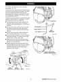
TIGHTENING
THE
ARM
AND
COLUMN
ADJUSTING
THE
COLUMN
TUBE
See Figure 18.
See Figures 19A - 19D.
There should be no play, vertical or horizontal, in the
arm relative to the column. If you can move the arm
up, down or sideways when the arm lock knob is
unlocked, use the following steps to tighten the arm.
The purpose of this procedure is to check whether the
inner column tube is snug in the housing and to
remove any looseness. Looseness could result in a
poor cut or difficulty in elevating the carriage. The
column tube is the upper portion of the column and
extends from the column support.
Note: The arm should pivot only when the arm lock
knob is unlocked and pulled forward to compress the spring.
•
Using a phillips screwdriver, remove the rear cover
screws (2) and rear cover from the back of the arm.
This uncovers the bolts on the column.
•
Tighten the top two bolts evenly until the arm is firm
and there is no vertical or horizontal movement.
•
Also check the two bottom hex nuts. It is not
necessary to tighten them as tight as the upper
bolts. However they should be tightened even and
snug.
•
Replace the rear cover and rear cover screws.
•
Tighten screws securely.
Note:
It is critical to remove all looseness with this
procedure. If this procedure is not done correctly, following adjustments will be wrong and
could result in machine damage.
This procedure checks both the elevating action and
the rotating action. If a check does not show looseness, do not perform the adjustment.
REAR
COVERSCREWS
•
If the arm is not at 0 ° (straight forward), release the
arm lock knob, set the arm, and re-lock the arm
lock knob.
•
Elevation check. To check the elevation movement,
place your hand under the front of the radial arm.
Press upward on the radial arm. There should be
no play between the column tube and the column
support. The whole assembly should move as one.
See Figure 19A.
COLUMN
TUBE
REAR
COVER
ARM
HEXBOLT(2)
COLUMN
SUPPORT
Fig. 19A
HEXNUT(2)
CR_FT_MRN °RADIAL SAW 315.273731
Fig. 18
26
•
Elevation
Rotation check: To check the rotation, hold the front
of the arm with one hand and grasp the top of the
column support with the other. Press the arm to the
side. If there is play between the column support
and the column tube, it needs to be adjusted. See
Figure 19B.
Adjustment
COLUMNTUBE
r
\
COLUMNSUPPORT
Fig. 19B
Fig. 19C
•
•
Elevation Adjustment. If the elevation check did not
show any play between the column tube and the
support, go to the rotation adjustment. Otherwise,
raise and lower the arm with the elevating handwheel. Tighten the black screws on the right side of
the column support by 1/16th to l/8th of a turn.
Tighten the two silver screws on the left side
slightly more. You will need two 1/2 in. wrenches or
sockets. Turn the elevating handwheel again. If the
column tube binds, loosen the silver and black
screws and turn the handwheel again. See Figure
19C.
•
Rotation Adjustment. Using a 3/16 in. hex key,
slightly tighten the two cap screws at the back of
the column support (left side) until no play shows
between the radial arm and the column. The cap
screws are indicated by arrows. See Figure 19D.
•
Recheck the rotation by holding the front of the
arm, grasping the top of the column support with
the other, and pressing the arm to the side.
Rotation Adjustment
When the elevation is smooth, check for looseness
again by pressing upward on the front of the arm.
Repeat the previous step until elevation is smooth
with no play between the column tube and the
column support.
CAP
SCREWS
Fig. 19D
27
rRRFT,_MRN° RADIALSAW 315.273731
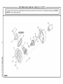
ADJUSTING
THE
CARRIAGE
BEARINGS
•
Use a 9/16 in. wrench to hold the eccentric screw
(top of bearing) and a 1/2 in. wrench to loosen the
nut below the bearing.
•
Turn the eccentric screw a partial turn as needed to
tighten the bearing.
•
Retighten the nut and repeat the second step to
test the tightness. Adjust it so the bearing turns
even against resistance when the carriage is
moved - but not so much that the carriage is difficult
to move and return it to its rear position.
•
Repeat for the left rear bearing.
See Figures 20A and 20B.
Loose carriage bearings permit the blade to wander
slightly while cutting, which will result in a poor cut
and more wear and tear on the saw. Use the following
steps to check for tightness and to then adjust the
bearings if needed.
•
On the left side of the arm, remove the carriage
lock knob, the carriage cover screws, and the
carriage cover.
•
With one hand, grip the front bearing hard to keep it
still, and pull the carriage forward with the other
hand. The bearing should turn. If it stays still as the
carriage is moved, it needs to be adjusted.
Note: Adjust bearings on the left side only. Bearings
on the right side do not adjust.
•
CARRIAGEBEARING
Replace the carriage cover, carriage cover screws,
and carriage lock knob.
ECCENTRICSCREW
GRASPAND HOLD
CARRIAGEBEARING
9/16 in.
WRENCH
1/2 in.
WRENCH
Fig. 20A
Fig. 20B
CRRF:I'$HRN° RADIALSAW 315.273731
28
LEVELING
THE
TABLE
SUPPORTS
•
Place the wrench below the shaft and check that
the clearance is the same. If not, adjust the table
support until it is the same. Securely tighten the
front screw.
•
Move the arm to the opposite side and repeat the
above procedure. When the opposite side is level,
recheck the first side to make sure that it is still
accurate and even.
•
Return the saw and motor to normal height and
position.
See Figures 2fA and 2fB.
The table supports must be perfectly level.
• Pull the bevel lock lever forward to unlock it. Use
the bevel index knob to rotate the motor so the
arbor shaft points down. Lock the bevel lock lever.
•
Release the arm lock knob to angle the arm. Begin
by positioning the arbor shaft over the back of the
highest table support. Normally this is the left side.
See Figure 21A.
•
Lock the arm lock knob and the carriage lock knob.
•
Using one of the blade wrenches as a feeler gage,
place it on the table support below the arbor shaft.
•
With the elevating handwheel, carefully lower the
motor until the shaft just touches the wrench. The
wrench should move with only slight resistance.
Securely tighten the back screw on the table
support.
•
Without changing the elevation, move the arm to
place the blade arbor over the front of table support. See Figure 21B.
ARM LOCK KNOB_
BEVEL
LOCKLEVER
BLADEWRENCH
AT BACK
BLADE
ARBOR
RIGHTSIDE
TABLESUPPORT
LEFT SlDE
TABLESUPPORT
ELEVATING
HANDWHEEL
Fig. 21A
29
rRRFTSMRN
° RADIALSAW315.273731
INSTALLING THE FRONT TABLE
U-CLIP
See Figures 22A - 22C.
ALIGN U-CLIP
OVERTHISHOLE
Use this procedure to install the fixed front table.
The top of the table has counterbored holes, predrilled
from the top, around the center to attach the table. In
the center are a counterbored hole and a small hole,
which is not counterbored. They are used for raising
or lowering the center of the table until it is level.
•
Locate the front table and the following hardware:
1
1
1
4
1
5
4
4
•
tee nut
U-clip (1/4 in.)
setscrew (1/4-20 x 7/8 in.)
pan head screws (1/4-20 x 1 in.)
pan head screw (1/4-20 x 1-3/4 in.)
flat washers (5/8 in.)
lock washers (1/4 in.)
hex nuts (1/4-20)
SAWBASE
Place the front table on a solid worksufface, with
the top surface face down. Place the tee nut in the
non-counterbored hole and tap it in place with a
hammer.
Fig. 22B
•
Place the long pan head screw into the center hole
and thread into the U-clip. Do not tighten until the
table has been checked for evenness. See Figure
22A.
•
Place the setscrew through the small leveling hole
and thread into the tee nut, but do not tighten.
•
Put a 1 in. long pan head screw in the four remaining holes and through the holes in the support.
Cap with a lock washer and hex nut. Tighten with a
7/16 in. wrench and phillips screwdriver. This
completes installation of the front table.
SETSCREW
_
_'/
SCREW
_
/
_____
TEE f
_
REAROF
FRONTTABLE
1 in,
SCREW
_
NUT
REAR OF FRONTTABLE
Fig. 22A
•
Snap the U-clip onto the front edge of the saw
base. Line up the hole in the U-clip with the saw
base hole just to the left of the center notch in saw
base. See Figure 22B.
•
Place the table, top up, on the table supports so the
center counterbored hole lines up over the hole in
the U-clip.
Place a flat washer in each counterbored hole.
•
!®/_,
X
HEX NUT
LOCKWASHER
Fig. 22C
CRRF:I'$HRN° RADIALSAW 315.273731
30
LEVELING
THE
FRONT
TABLE
INSTALLING
REAR TABLE,
SPACER
TABLE,
FENCE,
AND CLAMPS
See Figures 24A - 24C.
See Figure 23.
If there are any high or low areas on the front table,
they should be removed by adjusting the leveling
screws in the center holes on the front table.
•
Place the rear table on its edge across the front
table to check for gaps.
•
Adjust gaps of less than 1/32 in. in the center of
the table by turning the setscrew with a flat blade
screwdriver until the setscrew touches the frame.
The placement of the tables and fence may need to
be changed for different cuts, depending on the size
of the workpiece and the position of the blade. The
fence should be installed next to the front table for
maximum depth capacity; it should be installed in the
middle for maximum cross cut capacity; and installed
all the way back for maximum rip capacity.
•
Then lightly secure the center pan head screw with
a phillips screwdriver.
•
•
Fora gap of more than 1/32 in. in the center of the
table, raise the center by turning the setscrew
against the frame. Then lightly secure the center
pan head screw with a phillips screwdriver.
Locate the fence, the spacer table, the rear table,
and two unassembled clamps, which consist of the
following hardware:
2
2
2
2
For a gap of more than 1/32 in. on the sides, lower
the center of the table by tightening the center pan
head screw with a phillips screwdriver. Then tighten
the setscrew.
PHILLIPSSCREWDRIVER
ON PAN HEADSCREW
cup washers
clamp brackets
square nuts
thumbscrews
•
Place the fence behind the front table, then the
spacer table behind it, and then the rear table
behind it.
•
Slip a square nut into the slot of each clamp
bracket.
•
Place a thumbscrew into the end of the clamp
bracket farthest from the slot. Thread it into the
square nut.
SETSCREW
Note: If the screw is inserted in the wrong end of the
bracket, the clamp will not work.
•
Place the clamp bracket into the rectangle holes in
the table support. Hold the cup washer against the
rear table and turn the thumbscrew clockwise until
it snaps into the cup washer.
•
Tighten the thumbscrews to clamp the table sections into place.
REARTABLE
REARTABLE
FENCE
FRONTTABLE
Fig. 23
SPACERTABLE
FRONTTABLE
Fig. 24A
31
f'RRFT._MRN
_RADIALSAW 315.273731
INSTALLING
BLADE
AND
BLADE
GUARD
See Figures 25A and 25B.
•
Collect the blade and hardware that were removed
earlier. Place the inner blade washer, saw blade,
outer blade washer, and blade nut on the blade
arbor. See Figure 25A. Note: The flat concave side
of blade washers go against the blade.
•
Hold the blade arbor with one wrench and rotate
the other blade wrench counterclockwise (up), to
tighten the blade nut. See Figure 25B. Note: Blade
arbor has left hand threads. Test the blade to make
sure it turns freely.
•
Use the bevel index knob (above the handle) and
the bevel lock lever (below the handle) to set and
lock the motor at 0 °. The blade will be vertical.
•
Attach the blade guard over the blade so the riving
knife and pawls face front. See Figure 25A.
•
Tilt the guard approximately 45 ° down in the front,
place it over the blade, and rotate it to a horizontal
locked position.
•
Retighten the blade guard clamp screw, the long
thumbscrew located between the blade guard and
the motor.
•
Check that the guard is firmly seated in the groove
on the motor housing.
•
Tighten the guard clamp screw.
•
Replace the retaining screw and nut at the bottom
of the lower inner blade guard.
THUMBSCREW
CLAMP
BRACKET
SQUARENUT
CUP
WASHER
I
CLAMPSHOWN
ASSEMBLED
SLOT
_)
Fig. 24B
RECTANGLE
HOLE
THUMBSCREW
BLADEGUARD
BLADE
TABLE
SUPPORT
TO
LOOSEN
RETAINING
SCREWAND NUT
CUP
WASHER
RIVINGKNIFE
AND PAWLS
TO
TIGHTEN
TO
THUMB
SCREW
BLADE NUT
INNERBLADE
WASHER
Fig. 25A
LOOSEN
BLADE
ROTATION
TO
_HTEN
• BLADE
WRENCH(2)
BLADE
ARBOR
Fig. 24C
Fig. 25B
CRRFT_HRN° RADIALSAW 315.273731
32
ALIGN
RIVING
KNIFE
TO BLADE
•
With the elevating handwheel, lower the arm until
the blade just clears the table.
When ripping the riving knife must be centered with
the blade to ride in the middle of the kerf and keep it
from binding. Binding pinches the blade. Blade
pinching can cause kickback.
•
Support the lower outer blade guard and loosen the
carriage lock knob on the left of the arm. Move the
yoke back until the blade touches the fence. Reset
the carriage lock knob.
There are two pairs of anti-kickback
•
Loosen the riving knife knob, at the front of the
upper blade guard. Lower the riving knife to the
table and tighten the knob. tf the knife rests against
the fence, with one set of pawls riding on the fence,
no adjustment is needed.
•
If the riving knife is on the fence or not touching it,
loosen the riving knife slotted nut (just above the
pawls, to the right). Correct the riving knife position
and retighten the cap nut.
See Figures 26A - 26C.
pawls.
,_!1 WARNING:
Failure to use the riving knife, hold
downs, and anti-kickback pawls can allow
kickback. Kickback can throw the workpiece
toward the operator, resulting in serious injury.
•
Put the blade to the in-rip position by first loosening
the yoke lock handle, below the carriage on the
right. Then pull the yoke pivot latch (right side of
arm, on carriage) forward and rotate the yoke to the
left. This indexes the yoke 90 ° so the blade is
between the motor and the column. Lock the yoke
lock handle.
CARRIAGELOCK KNOB
YOKELOCKHANDLE
RIVINGKNIFE
KNOB
RIVINGKNIFE
SLOTTEDNUT
LOWEROUTER
BLADEGUARD
RIVINGKNIFETOO
FAR RIGHTOF FENCE
AND BLADE
RIVINGKNIFE
BLADEGUARD
ANTI-KICKPAWLS
.3KPAWLS
FRONTTABLE
Fig. 26A
FENCE
CORRECTALIGNMENTOFTHE RIVINGKNIFE
AND ANTI-KICKPAWLS
Fig. 26C
RIVINGKNIFEONTOP OF FENCE
TOO FARLEFTOF BLADE
Fig. 26B
33
rRRFTSMRN
° RADIALSAW 315.273731
INSTALLING
RIP SCALE
SCREWS
INDICATORS
See Figure 27.
RIP SCALE
INDICATOR
The rip scale indicators on the arm show the distance
between the blade and the rip fence with the fence in
the front and rear positions. The upper scale is used
when the fence is positioned directly behind the front
table. The lower scale is used when the fence is at the
extreme rear, directly in front of the column.
SPEEDNUT
CARRIAGE
COVER
The In-Rip Indicator is on the right side of the arm.
The Out-Rip Indicator is on the left side of the arm.
•
Remove the following from a small hardware bag.
SPRING
2 rip scale indicators
4 screws
CARRIAGE
LOCK KNOB
2 speed nuts
•
On the left of the radial arm saw, remove the
carriage lock knob and spring.
•
Remove the two carriage cover screws and the
carriage cover.
•
Insert a speed nut inside the carriage cover with the
flat side up. Place the scale indicator on top of the
carriage cover and attach with two screws. Securely tighten screws.
•
Replace the carriage cover and tighten the carriage
cover screws.
•
Replace carriage lock knob and spring.
•
Repeat for the right side.
Fig. 27
To complete setting up your saw, continue with the
Adjustment procedures. The adjustments should be
checked regularly, depending on usage. Your saw will
provide accurate cuts with fine tolerances as long as
you protect the accuracy with frequent alignment
checks. The radial arm saw can perform a wide range
of high quality cuts.
The final step will be connecting the control cut
device. The control cut device offers many benefits.
As it increases operator control, it eliminates the risk
in a cross cut of the saw "climbing" out and over the
workpiece at the operator. Feed control of the blade
as it cuts through the workpiece increases, as does
the accuracy of the cut. The following adjustments
need to be completed before the control cut device is
connected.
Your radial arm saw is designed to perform a variety
of complex cuts with fine tolerances. A weekly alignment check ensures that your saw can perform with
precision. It takes about ten minutes and the results is
better performance and a longer life for your saw.
_
Perform the checks in the order given. If you miss an
adjustment, go back to the missed adjustment and
repeat all steps from that point forward.
CRR$:I'$HR_J
_RADIALSAW 315.273731
SCREWS
34
CAUTION:
Failure to check alignments and
perform the adjustments in the initial set up or on
a frequent basis can result in poor performance
or machine damage.
ALIGNING
THE
ARM
FOR
CROSS
CUTS
•
Release the arm lock knob. Position the arm
straight forward (0 °) and leave it unlocked.
•
Lower the arm with the elevating handwheel until
the saw blade just clears the front table. Lock the
yoke lock handle (right side of saw, below yoke)
and the bevel lock lever.
•
Place the framing square on the table and position
one edge of the square firmly against the back
edge of the table. Position the other leg of the
square against the blade until it rests beside but not
touching a tooth. With a pencil, mark beside this
tooth.
•
Slowly move the yoke assembly forward and
backward along the arm and against the square
without rotating the blade. If the mark moves into or
away from the square, adjust the arm with the
following steps.
•
At the back of the column, loosen the three setscrews with a 3/16 in. hex key and position the arm
as needed to align with the framing square.
•
Lock the arm lock knob and retighten the three
setscrews. Recheck the cross cut travel with the
blade against the framing square.
•
Set the miter indicator on top of the column to 0 °.
•
Replace the fence, spacer table, rear table, and
table clamps.
See Figures 28A - 28C.
This procedure checks whether the arm is exactly 0 °
for cross cut travel by checking the blade against the
table and the miter indicator. Remove the rear table,
spacer table, and fence, but leave the front table in
place. You will need a framing square, a 3/16 in. hex
key, and a pencil.
,_
WARNING:
Be sure the saw is unplugged
before performing these adjustments. Accidental
start-up could result in serious personal injury.
•
First check the framing square by fitting one side
against the back edge of the table. Lightly draw a
line on the table along the edge of the square in
the middle of the table. Flip the square over. If the
edge still matches the line with no gaps or overlaps, the square is true.
STRAIGHT
EDGE
DRAWA STRAIGHT
LINEALONGTHIS EDGE ,
m
FRAMING
SQUARE
REARCOVER
REMOVEDFOR
CLARITY
THERESHOULDBE NOGAP HEREWHEN
SQUAREIS FLIPPEDOVERTO DOTTEDPOSITION
Fig. 28 A
MITERINDICATOR
ARM
LOCKKNOB
/
SETSCREWS
)
YOKE
LOCK
HANDLE
FRAMING
SQUARE
SETSCREWS
ELEVATING
HANDWHEEL
Fig. 28 C
Fig. 28 B
35
CRRFT=_MRN
° RADIALSAW315.273731
ALIGNING
BLADE
TO TABLE
AT 0 ° BEVEL
•
If there are no gaps, fully tighten each screw. If
there is still a gap, repeat the previous two steps.
This procedure squares the blade to the table at 0 °
bevel (vertical) so the blade angle will be accurate. If
the blade is not at 0 ° bevel, follow the steps below to
rotate slightly. You will need a framing square and a
1/4 in. hex key.
• Position the blade in front of the fence. Lower the
•
Check the bevel indicator on the yoke assembly
near the handle. It should read 0 °. If it does not,
reset it by loosening the screws and rotating the
bevel index cap. Retighten the two screws.
•
Loosen the carriage lock knob.
See Figures 29A - 29D.
BLADESQUARETO TABLE
blade with the elevating handwheel until it just
clears the front table.
•
•
Lock the following controls:
bevel lock lever below the handle,
carriage lock knob on the left side,
arm lock knob on top of the arm, and
yoke lock handle below the yoke, on the right.
NOADJUSTMENTNEEDED
FRAMING
SQUARE
Stand a framing square on the table with the short
leg pointing up against the saw blade and the long
leg parallel to the fence. Place the square flat
against the blade between two teeth.
•
If both the top and bottom of the saw blade are flat
against the square, no adjustment is needed.
•
If the saw blade gaps at the top or bottom, remove
the bevel index cap by removing the two phillips
head screws (below the handle). You will see four
socket head screws.
•
Loosen the socket head screws with a 1/4 in. hex
(
BLADE
TABLE/
Fig. 29B
FRAMING
SQUARE
/
GAP/
key. Rotate the motor slightly while holding the
square against the saw blade and table top.
•
_
Slightly tighten each of the four screws and recheck
the blade and framing square.
GAP
BLADE
ARMLOCKKNOB
t
BLADE
GAP-ADJUSTMENTNEEDED
Fig. 29C
BEVEL
INDEXCAP
BEVELINDEX
CAP REMOVED
BEVEL
LOCK
LEVER
FRONTTABLE
ELEVATING
HANDWHEEL
SOCKET
HEADSCREWS
Fig. 29A
BEVEL
LOCKLEVER
Fig. 29D
rRRFTSMRN° RADIALSAW 315.273731
36
SQUARING
BLADE
See Figures 30A - 30C.
TO FENCE
This procedure squares the miter angle of the blade to
the fence to reduce the risk of binding and kickback. If
the blade is not square to the fence, the yoke assembly must be rotated slightly. Have a framing square, a
1/2 in. wrench, and a phillips screwdriver at hand. The
blade should be lowered to just clear the table.
Release the carriage lock knob.
_,
•
Release the yoke lock handle (below the yoke on
the right). With a 1/2 in. wrench, slightly loosen the
two hex bolts holding the yoke pivot latch.
•
Rotate yoke assembly until the gap is eliminated.
•
Lock the yoke lock handle. Retighten the two hex
bolts on the yoke pivot latch.
•
Replace the carriage cover.
•
Loosen the carriage lock knob and guide the yoke
assembly to the back of the arm.
SAW VIEWED
WARNING:
The blade must be angled at 90 ° to
the fence when the handle is at the front of the
saw. If not, kickback could result during a cross
cut. Kickback can cause serious injury by throwing the workpiece toward the operator, tn addition, a faulty miter angle on the blade can splinter
or burn the cut edges of the workpiece during
cross cuts or rip cuts.
•
Use the arm lock knob to index and lock the arm in
0 ° miter position (straight forward).
•
Pull the yoke assembly forward to the front of the
arm. Lock the carriage lock knob.
•
Place the short end of the framing square against
the fence. Rotate the square to 45 ° to the table.
Place the long edge across the flat surface of the
blade, below the center of the blade. (Do not place
the edge against a tooth.)
•
Check whether the blade is fiat against the edge for
the entire length or whether a gap is visible.
•
If the blade needs adjustment, remove the right side
carriage cover with a phillips screwdriver.
NO ADJUSTMENTNEEDED
ARM LOCKKNOB
FRAMING
SQUARE
BLADE
FENCE
GAPADJUSTMENTNEEDED
Fig. 30B
FENCE
HEX B_L__
FRAMINGSQUARE
YOKELOCKHANDLE
Fig. 30C
Fig. 30A
37
CP,
RFTSMRN° RADIAL SAW315.273731
PARALLELING
BLADE
TO TABLE
•
Check whether the blade is flat against the edge
the entire length or whether a gap is visible. If you
can see a gap, adjust the blade to be at 90 ° bevel
to the table with the following steps.
•
Unlock the bevel lock lever. Loosen the rear motor
mount nut, which holds the motor on the yoke.
Place a flat blade screwdriver in one of the slots,
and rotate the cam behind the nut to eliminate the
gap between the blade and the square.
•
Retighten the nut.
•
Tighten the bevel lock lever. Recheck the blade
and the square for any gaps.
•
Raise the blade with the elevating handwheel to
approximately halfway up. Index the blade to a
vertical 0 ° bevel with the bevel index knob. Lock it
with the bevel lock lever.
See Figures 31A-31C.
This procedure squares the blade to the table at 90 °
bevel so horizontal cuts will be accurate. This also
reduces kickback, as well as splintering and burning
of the cut edges of the workpiece. If the blade is not at
90 ° bevel, follow the steps to rotate the blade unit
slightly. You will need a framing square and a flat
blade screwdriver.
_lk WARNING:
The blade must be perfectly parallel
to the table at the 90 ° reading on the bevel scale.
If not, kickback could result, as well as splintering or burning the cut. Kickback can result in
serious personal injury as the workpiece can be
thrown at the operator.
•
Use the arm lock knob to lock the arm in 0 ° miter
position (straight forward).
•
Turn the elevating handwheel to raise the blade at
least 2 in. above the table.
•
Release the bevel lock lever below the handle. Use
the bevel index knob, just under the handle, to turn
the motor to 90 °. The blade will be horizontal. Lock
the bevel lock lever.
•
Place the framing square with the short end hanging down in front of the worktable and the long side
on edge under the blade.
•
Lower the arm with the elevating handwheel so the
blade surface rests on the square. Turn the blade
slightly if necessary so the face of the blade, not a
tooth, lies on the square.
ADJUSTMENT
NEEDED
GAP
NOADJUSTMENT
NEEDED
Fig. 31B
BEVEL
LOCK
LEVER
FENCE
CAM
BLADE
/
FRONTTABLE
FRAMING_
SQUARE
Fig. 31A
Fig. 31C
rRRF'[SMRN° RADIALSAW 315.273731
38
ALIGNING
THE
RIP SCALE
INDICATORS
•
On the right side of the arm, check the lower in-rip
scale indicator, which should be set on 0 inches. If
it is not, loosen the screws and shift the indicator
until it reads zero. Tighten the screws.
•
Loosen the yoke lock handle. Pull the yoke pivot
latch forward and rotate the yoke to the out-rip
position. The blade should be in front of (outside)
the motor and the column.
•
Lay the framing square on the table with the short
edge against the fence and with the long side
toward the table front.
•
Note the distance where the blade contacts the
framing square.
•
On the left side of the arm on the out-rip scale,
check the rip scale indicator on the rear fence
position (lower scale). The rip scale indicator should
mark the same number as the distance measured
from the fence to the blade. If it does not, loosen
the screws and shift the scale until the indicator is
correct. Tighten the screws.
See Figures 32A - 32B.
The rip scale indicators on the arm show the distance
between the blade and the rip fence. The upper scale
is used when the fence is positioned directly behind
the front table. The lower scale is used when the
fence is at the extreme rear, directly in front of the
column.
The in-rip indicator and scale are on the right side of
the arm. The out-rip indicator and scale are on the left
side.
This procedure checks the indicators with the fence at
the back of the tables directly in front of the column.
The blade should be turned to the in-rip position to set
the rip scale indicator on the right side of the arm.
Then, the blade should be turned to the out-rip
position to set the rip scale indicator on the left side of
the arm. You will need a framing square.
•
If the fence is not at the rear of the tables, place it
there.
•
Turn the blade to the in-rip position by loosening
the yoke lock handle, below the arm on the right.
Then pull the yoke pivot latch forward and rotate
the yoke to the in-rip position. This indexes the
yoke 90 ° so the blade is between the motor and
the column. Lock the yoke lock handle.
•
With the elevating handwheel, lower the arm until
the blade just clears the table.
•
Loosen the carriage lock knob and guide the blade
back to just touch the fence. Tighten the carriage
lock knob.
OUT-RIPSCALEON LEFTSIDE OF ARM
RIP-SCALEINDICATOR
Front
Fence
Position
_
2
3
4
.eo.Fence
oe,.on
IN-RIPSCALEON RIGHTSIDE OF ARM
RIP-SCALEINDICATOR
CARRIAGELOCK KNOB
Fig. 32B
s,,,oo
YOKEPIVOT LATCH
Fig. 32A
39
CP,
RFTSMRN° RADIAL SAW315.273731
INSTALLING
CONTROL
CUT
DEVICE
•
Plug in the control cut cord, leaving the main power
cord disconnected. Squeeze the switch trigger to
confirm the control cut motor is receiving power.
•
On the left side of the saw, remove the carriage
lock knob and spring. Remove the two screws that
attach the carriage cover and remove the cover.
•
Replace the spring and carriage lock knob. Pull the
carriage assembly about halfway to the front.
Tighten the carriage lock knob.
•
Squeeze the switch trigger in the handle with your
right hand and pull the spring loaded cable from the
column with your left hand. If you prefer to use a
pair of pliers, do not damage the cable. Note: Do
not to let the spring loaded cable clamp slip out of
your hand or pliers. If it slips past the cable bracket
and goes up into the control cut motor housing,
then disassembly of the control cut assembly will be
required to get it back out.
•
Place the barrel fitting into the socket at the back of
the carriage assembly.
•
Remove the carriage lock knob and spring. Replace
the carriage cover and screws, then replace the
spring and carriage lock knob.
•
Set the speed thumbwheel, using the chart on the
label. If you are unsure of the proper speed setting,
use the lowest setting.
See Figure 33.
Note: Before installing the control cut device, the yoke
assembly will travel back and forward on the
carriage by pulling the handle. After installing
the control cut device, the power cord for the
control cut device must be plugged in and
switch trigger pressed to move the yoke
assembly and carriage on the arm.
_
WARNING:
Do not install the control cut device
until after all of the initial adjustments and
alignments are made to prevent accidental
starting of the saw that could result in serious
personal injury.
The control cut device offers many benefits. As it
increases operator control, it eliminates the risk in a
cross cut of the saw "climbing" out and over the
workpiece at the operator. Feed control of the blade
as it cuts through the workpiece increases, as does
the accuracy of the cut.
The control cut cable maintains a steady pull on the
carriage assembly from the column. This tension
keeps the assembly at the column, unless you
squeeze the switch trigger in the handle. The switch
trigger activates the motor to counter the pull of the
cable.
After a cut is completed, press the switch on the arm
off, then release the switch trigger to prevent further
forward motion. Hold the handle until the blade has
BARREL
FITTING
stopped rotating. The yoke assembly will not roll
forward unless you are squeezing the switch trigger.
The control cut power cord is designed to operate on
a single voltage AC circuit. The speed can be set with
a thumbwheel on top of the handle. The three speed
settings are described on the label located on the left
side of the control cut housing.
_
WARNING:
Do not use the saw without the
control cut and blade guards in place unless
specifically instructed to do so. Otherwise
uncontrolled contact with the blade could occur,
resulting in personal injury.
_
WARNING:
Take great care when working with
either cord to ensure you have the correct one. If
you intend to unplug the main power cord but
remove the control cut cord instead, the
blade could be accidentally started and cause
injury.
CARRIAGE
ASSEMBLY
SOCKET
rRRI:I'SH RN° RADIAL SAW 315.273731
40
Fig. 33
BASIC OPERATION
ARM SAW
OF THE
RIP CUTS
RADIAL
In rip cuts, the yoke is rotated 90 ° left or right and
locked in place. The wood must ride firmly against the
rip fence. There are two orientations of rip cuts - the
in-rip and the out-rip. The in-rip position provides
better visibility. Out-rip cuts can also be made with the
blade beveled.
A radial arm saw can be used for straight-line cutting
operations such as cross cutting, ripping, mitering,
beveling, compound cutting, and resawing. It can
make dado or molding cuts with special attachments.
This saw is designed to cut wood and wood composition products only.
In an in-rip cut, the yoke is rotated to the left, which
puts the blade in between the column and the motor.
The wood is fed from the right hand side.
The three-prong plug must be plugged into a matching outlet that is properly installed and grounded
according to all local codes and ordinances. Improper
connection of the equipment can result in electric
shock. Check with an electrician or service personnel
if you are unsure about proper grounding. Do not
modify the plug; if it will not fit the outlet, have the
correct outlet installed by a qualified electrician. Refer
to the Electrical page of this manual.
TYPES
In an out-rip cut, the blade is in front of the motor, and
the wood is fed from the left. Out-rip cutting is recommended only when the blade is set 12 in. or more
from the fence.
,_
OF CUTS
See Figure 34.
The radial saw makes cross cuts parallel with the arm
(across the grain), and rip cuts square to the arm (with
the grain). Each can be made with the blade vertical
or beveled. Instructions for making each kind of cut
are given later in this section.
,_
,_iL WARNING:
Always use a pushstick with small
pieces of wood, and also to finish the cut when
ripping a long narrow piece of wood, to prevent
your hands from getting close to the blade.
WARNING:
All blades and cutting accessories
must be rated for at least 5,000 rpm to prevent
possible injury.
CROSS
WARNING:
Always make sure the blade guard
and anti-kickback pawls are in place and working
properly when making rip cuts to avoid possible
injury.
Q
_
_CROSS
CUTS
Cross cuts are made parallel to the arm. The blade is
pulled along the length of the radial arm with the wood
secured.
__
There are several types of cross cuts. A cross cut
shows 0° on the miter scale (arm straight) and 0 ° on
the bevel scale (blade straight). A miter cut is made
with the radial arm angled and the blade straight. A
bevel cut is produced with the arm straight and the
blade angled.
MITERCUT
BEVEL CUT
A final type of cross cut is the compound cross cut.
Both the arm and the blade are angled. Be thoroughly
familiar with making cross cuts, bevel cuts, and miter
cuts before trying a compound miter cut.
4_
Note: In cross cuts, the blade teeth point down as
they strike the wood. In rip cuts, the teeth point
up as they strike the wood.
t_
,_k
CUT
_
COMPOUNDCROSSCUT
RIP CUT
WARNING:
NEVER make a cross cut with the
short edge of the wood parallel to the fence. Kick
back is likely to occur, causing the workpiece to
be thrown back at you. Treat such a workpiece
as a rip cut.
®
____BEVEL
RIPCUT
Fig. 34
41
CR_I:TSHRN° RADIAL SAW315.273731
SWITCH
AND
SWITCH
L_
KEY
See Figures 35-37.
The main power switch has been placed on the front
of the arm for easy access. The yellow switch key
prevents accidental starting of the main power switch
when saw is not being used. To activate the switch,
insert the switch key and lift switch to ON position. To
lock the switch once it has been pressed to OFF,
remove the yellow key. Place the key in a location that
is inaccessible to children and others not qualified to
use the tool.
CAUSES
OF KICKBACK
INSERTSWITCHKEY
Kickback can occur when the blade stalls or binds,
kicking the workpiece back toward you with great
force and speed. If your hands are near the blade,
they may be jerked loose and contact the blade.
Obviously, kickback can cause serious injury and it is
well worth using precautions to avoid the risks.
Fig. 35
Kickback can be caused by any action that pinches
the blade in the wood, such as the following:
•
Making a cut with incorrect blade depth
•
Sawing into knots or nails in the workpiece
•
Twisting the wood while making a cut
•
Failing to support work
•
Forcing a cut
•
Cutting warped or wet lumber
•
Misusing the saw
•
Not following correct operating procedures
•
Using the wrong blade for the type of cut
•
Cutting with a dull, gummed-up, or improperly set
blade.
AVOIDING
Fig. 36
KICKBACK
•
Always use the correct blade depth setting. The
outer point of the blade teeth should clear the lower
surface of the workpiece by 1/8 in. to 1/4 in. when
making these cuts.
•
Inspect the work for knots or nails before beginning
a cut. Knock out any loose knots with a hammer.
Never saw into a loose knot or nail.
•
Always use the fence when rip cutting. This helps
prevent twisting the wood in the cut.
•
Always use clean, sharp, and properly-set blades.
Never make cuts with dull blades.
•
To avoid pinching the blade, support the work
properly before beginning a cut.
•
SWITCHON
SWITCHOFF
When making a cut, use steady, even pressure.
Never force cuts.
GRRFTSHRN
° RADIALSAW 315.273731
42
Fig. 37
•
Do not cut wet or warped lumber.
•
Always hold your workpiece firmly with both hands
or with pushsticks. Keep your body in a balanced
position to be ready to resist kickback should it
occur. Never stand directly in line with the blade.
•
Use the right type of blade for the cut being made.
•
Use the riving knife and anti-kickback pawls when
performing rip cuts.
CUTTING
AIDS
See Figures 38-40.
Cutting aids are used to improve the setup and help
make the operator's work safer and more accurate.
They can be made from scrap wood and in various
sizes and shapes for specific projects.
The basic types are pushsticks, pushblocks, and
featherboards. If the blade is set 2 in. or more from
the fence, use a pushstick. Use a pushblock when the
blade is between 1/2 in. and 2 in. from the fence. (If
the cut is narrower than 1/2 in., use a different saw.)
Refer to the drawings and instructions provided so
you can make safer and more precise cuts.
PUSHSTICKS
Fig. 38
PUSHSTICKS
See Figure 38.
Pushsticks must be narrower than the workpiece, with
a 90 ° notch in one end and shaped for a grip on the
other end.
4;;>4;>
PUSHBLOCKS
See Figure 39.
A pushblock has an upright handle with a base
attached to the handle. Some pushblocks have a foot
that extends down from the base and against the
workpiece. The foot is attached to the base with glue
only to prevent damage to the blade.
FEATHERBOARDS
PUSHBLOCKS
Fig. 39
FEATHERBOARD
Fig. 40
See Figure 40.
Featherboards are used for large panels, along with
an auxiliary table and a C-clamp. A featherboard has
an angled end to fit against the edge of the workpiece.
It is clamped in place so the workpiece moves between either the fence and the featherboard or the
table and featherboard. Slots in the end of the
featherboard help resist kickback and allow for
variations in the width of the workpiece.
_
Note: The Pushstick designs above are for illustration
purposes only. They have not been drawn to
scale.
WARNING:
Clamp the featherboard against the
infeed side of the workpiece. If clamped behind
the blade, it could squeeze the cut edges
together, causing binding and kickback. Kickback
can cause serious injury.
43
CRRFTSMIqN° RADIALSAW315.273731
MAKING
A CROSS
CUT
•
If the blade is angled, raise the plastic lower guard,
release the bevel lock lever, and set the bevel
indicator to zero. Retighten the bevel lock lever.
•
If the blade is in front of the fence, loosen the
carriage lock knob on the left side of the arm.
Release the switch trigger and let the carriage
return to the back.
•
If there is no kerf, cut one approximately 1/16 in.
deep. Grasp the handle and turn the saw on with
the switch on the arm. Squeeze the switch trigger
on the handle and pull the blade forward across the
table to make the kerf.
•
Release the switch trigger and let the carriage
return to the back. Turn the saw off with the switch
on the arm but hold the handle until the blade stops
rotating. Adjust the height with the elevating
handwheel so the blade will rotate freely in the kerf.
See Figure 41.
Use this procedure to make a cut with the blade
vertical and straight forward. If a kerf does not exist for
the line of the cut (cutting path), follow the steps to
make one. Each cutting path requires its own kerf.
,_
WARNING:
Make sure the blade guard is
lowered and is working properly to prevent
possible injury. Always raise the clear plastic
guard before changing the bevel or lowering the
blade to avoid damage to the guard.
,_
WARNING:
Keep one hand on the handle until
the blade stops rotating to prevent the risk of
injury.
•
Put the fence in the front position (next to the front
table) and tighten the table clamps.
•
•
Check that the control cut device is set for the
correct speed for the type of wood and cut you are
planning. Refer to the chart on the label and adjust
the thumbwheel on the handle accordingly.
Position the workpiece against the fence. Place the
pawls and riving knife to clear the workpiece or the
fence, whichever is higher, by at least 1/4 inch.
•
If the yoke is not in the cross cut position with the
blade parallel to the arm, release the yoke lock
handle (right side, under yoke). Position the yoke
correctly with the yoke pivot latch.
Grasp the handle with one hand. With the other,
turn the saw on, then hold the workpiece down and
against the fence. Keep your hand well away from
the blade.
•
Squeeze the switch trigger on the handle and pull
the blade through the workpiece but only far
enough to complete the cut. Keep your hand on the
handle, even after the cut has been made and the
saw turned off, until the blade stops rotating.
•
After completing the cut, move the workpiece to the
side and turn off the saw with the switch on the
arm. Release the switch trigger on the handle and
let the yoke move back behind the fence. Do not
release the handle until the blade stops rotating.
•
•
•
If the arm is too low or too high, first lift the blade
guard if the arm is too low, and turn the elevating
handwheel at the front of the table. Set the blade to
just clear the kerf or table.
If the arm is angled, release the arm lock knob on
top of the arm, position it straight ahead and lock
the arm lock knob.
ARM LOCK
HANDLE
SWITCH
CARRIAGE
LOCKKNOB
HANDLE
TABLECLAMPS
BEVEL
:K LEVER
CROSSCUT
RIVINGKNIFE
ELEVATING
HANDWHEEL
Fig. 41
CRRFTSMRN
_RADIALSAW315.273731
44
MAKING
A MITER
CUT
•
If the blade is in front of the fence, loosen the
carriage lock knob on the left side of the arm and
let the carriage move back.
•
If there is no kerf, cut one approximately 1/16 in.
deep. Grasp the handle and turn the saw on with
the switch on the arm. Squeeze the switch trigger
on the handle and pull the blade forward across the
table to make the kerf.
•
Release the switch trigger and let the carriage
return to the back. Turn the saw off with the switch
on the arm but hold the handle until the blade stops
rotating. Adjust the height with the elevating
handwheel so the blade will rotate freely in the kerf.
•
Position the workpiece against the fence. Place the
pawls and riving knife to clear the workpiece or the
fence, whichever is higher, by at least 1/4 inch.
•
Grasp the handle with one hand. With the other,
turn the saw on, then hold the workpiece down and
against the fence. Keep your hand well away from
the blade.
•
Squeeze the switch trigger and pull the blade
through the workpiece but only far enough to
complete the cut. Keep your hand on the handle,
even after the cut has been made and the saw
turned off, until the blade stops rotating.
•
After completing the cut, move the workpiece to the
side and turn off the saw with the switch on the
arm. Release the switch trigger and let the yoke
move back behind the fence. Do not release the
handle until the blade stops rotating.
See Figure 42.
In a miter cut, the blade is vertical and the arm
angled. If a kerf does not exist for the cutting path,
make one (instructions below). Each cutting path
requires its own kerf.
,_
,_
WARNING:
Make sure the blade guard is
lowered and is working properly to prevent
possible injury. Always raise the clear plastic
guard before changing the bevel or lowering the
blade to avoid damage to the guard.
WARNING:
Keep one hand on the handle until
the blade stops rotating to prevent the risk of
injury.
•
Put the fence in the front position (next to the front
table) and tighten the table clamps.
•
Check that the control cut device is set for the
correct speed for the type of wood and cut you are
planning. Refer to the chart on the label and adjust
the thumbwheel on the handle accordingly.
•
If the yoke is not in the cross cut position with the
blade parallel to the arm, release the yoke lock
handle and position the yoke correctly with the
yoke pivot latch on the right side of the arm.
•
If the arm is too low or too high, first lift the blade
guard if the arm is too low, and turn the elevating
handwheel at the front of the table. Set the blade to
just clear the kerf or table.
•
To set the angle of the arm, release the arm lock
knob on top of the arm. Use the miter scale above
the column to position the arm to the desired angle,
and lock the arm lock knob.
ARM
LOCKKNOB
If the blade is angled, raise the plastic lower guard,
release the bevel lock lever, and set the bevel
indicator to zero. Retighten the bevel lock lever.
SWITCH
•
MITERSCALE
YOKE
PIVOT LATCH
CARRIAGE
LOCK
YOKELOCK
HANDLE
BLADEGUARD
BEVEL
INDICATOR
BEVEL
LOCKLEVER
ERCUT
TABLE
CLAMP
ELEVATING
HANDWHEEL
45
Fig. 42
CRRFTSHRN° RADIALSAW315.273731
MAKING
A BEVEL
CUT
•
Release the switch trigger and let the carriage
return to the back. Turn the saw off with the switch
on the arm but hold the handle until the blade stops
rotating. Adjust the height with the elevating
handwheel so the blade will rotate freely in the kerf.
•
Position the workpiece against the fence. Place the
pawls and riving knife to clear the workpiece or the
fence, whichever is higher, by at least 1/4 inch.
•
Grasp the handle with one hand. With the other
hand, turn the saw on, then hold the workpiece
down and against the fence. Keep your hand well
away from the blade.
•
Squeeze the switch trigger on the handle and pull
the blade through the workpiece but only far
enough to complete the cut. Keep your hand on the
handle, even after the cut has been made and the
saw turned off, until the blade stops rotating.
•
After completing the cut, move the workpiece to the
side and turn off the saw with the switch on the
arm. Release the switch trigger on the handle and
let the blade move back behind the fence. Do not
release the handle until the blade stops rotating.
See Figure 43.
This procedure makes a cut with the blade and motor
angled and the arm straight (90 ° to fence). If there is
no kerf, follow the steps to make one. Try this cut on
scrap wood before cutting your workpiece.
,_
,_
WARNING:
Make sure the blade guard is
lowered and is working properly to prevent
possible injury. Always raise the clear plastic
guard before changing the bevel or lowering the
blade to avoid damage to the guard.
WARNING:
Keep one hand on the handle until
the blade stops rotating to prevent the risk of
injury.
•
Put the fence in the front position (next to the front
table) and tighten the table clamps.
•
Check that the control cut device is set for the
correct speed for the type of wood and cut you are
planning. Refer to the chart on the label and adjust
the thumbwheel on the handle accordingly.
•
If the yoke is not in the cross cut position with the
blade parallel to the arm, release the yoke lock
handle and position the yoke correctly with the yoke
pivot latch on the right side of the arm.
•
•
BEVELEDCUT
ARM_
LOCKKNOB
If the arm is too low or too high, first lift the blade
guard if the arm is too low, and turn the elevating
handwheel at the front of the table. Set the blade to
just clear the kerf or table.
SWITCH
If the arm is angled, release the arm lock knob on
top of the arm, position it straight ahead and lock
the arm lock knob.
•
If the blade is in front of the fence, loosen the
carriage lock knob on the left side of the arm.
Release the switch trigger on the handle and let the
carriage return to the back.
•
To set the blade angle, first raise the plastic lower
guard. Release the bevel lock lever, and position
the blade with the bevel index lever. Retighten the
bevel lock lever.
HANDLE
RIVING
KNIFE
Note: For a 45 ° or 90 ° angle, the bevel index lever will
seat automatically at the preset positive stop
positions. For any other angle, use the bevel
lock lever.
•
YOKE LOCK
HANDLE
ELEVATING
HANDWHEEL
If there is no kerf, cut one approximately 1/16 in.
deep. Grasp the handle and turn the saw on with
the switch on the arm. Squeeze the switch trigger
on the handle and pull the blade forward across the
table to make the kerf.
Fig. 43
CRAFfSMRN_RADIALSAW 315.273731
46
MAKING
A COMPOUND
CROSS
CUT
•
If the yoke is in front of the fence, loosen the
carriage lock knob on the left side of the arm.
Release the switch trigger on the handle and let the
carriage return to the back.
•
WARNING:
Make sure the blade guard is
lowered and is working properly to prevent
possible injury. Always raise the clear plastic
guard before changing the bevel or lowering the
blade to avoid damage to the guard.
If there is no kerf, cut one approximately 1/16 in.
deep. Grasp the handle. Turn the saw on with the
switch on the arm. Squeeze the switch trigger and
pull the blade forward to make the kerf.
•
WARNING:
Keep one hand on the handle until
the blade stops rotating to prevent the risk of
injury.
Release the switch trigger and let the carriage
return to the back. Turn the saw off with the switch
on the arm but hold the handle until the blade stops
rotating. Adjust the height with the elevating
handwheel so the blade will rotate freely in the kerf.
•
•
Put the fence in the front position (next to the front
table) and tighten the table clamps.
Position the workpiece against the fence. Place the
pawls and riving knife to clear the workpiece or the
fence, whichever is higher, by at least 1/4 inch.
•
•
Check that the control cut device is set for the
correct speed for the type of wood and cut you are
planning. Refer to the chart on the label and adjust
the thumbwheel on the handle accordingly.
Grasp the handle with one hand. With the other
hand, turn the saw on, then hold the workpiece
down and against the fence. If necessary, slightly
raise the outer blade guard for clearance. Keep
your hand well away from the blade.
•
If the yoke is not in the cross cut position with the
blade parallel to the arm, release the yoke lock
handle and position the yoke correctly with the yoke
pivot latch on the right side of the arm.
•
Squeeze the switch trigger and pull the blade
through the workpiece but only far enough to
complete the cut. Keep your hand on the handle,
even after the cut has been made and the saw
turned off, until the blade stops rotating.
•
If the arm is too low or too high, first lift the blade
guard if the arm is too low, and turn the elevating
handwheel at the front of the table. Set the blade to
just clear the kerf or table.
•
•
To set the angle of the arm, release the arm lock
knob on top of the arm. Use the miter scale above
the column to position it to the desired angle, and
lock the arm lock knob.
After completing the cut, move the workpiece to the
side and turn off the saw with the switch on the
arm. Release the switch trigger and let the yoke
move back behind the fence. Do not release the
handle until the blade stops rotating.
See Figure 44.
In this cut, both the blade and the arm are angled. Be
familiar with both bevel and miter cuts before making
a compound cut. Practice on scrap wood.
,_
,_
•
•
MITERSCALE
ARM
LOCK
To set the blade angle, first raise the plastic lower
guard. Release the bevel lock lever, and position
the blade with the bevel index lever.
SWITCH
YOKE
PIVOT LATCH
YOKELOCK
Retighten the bevel lock lever.
Note: For a 45 ° or 90 ° angle, the bevel index lever will
seat automatically at the preset positive stop
positions. For any other angle, use the bevel
lock lever.
HANDLE
BEVEL LOCK
LEVER
CLAMPS
BEVELED AND
ELEVATING
HANDWHEEL
Fig. 44
47
CRRFTSMRN
° RADIALSAW315.273731
RiP CUT
HAZARDS
AND
PRECAUTIONS
SETTING
UP A RiP
CUT
See Figure 45.
Two hazards are specifically associated with rip
cutting: outfeed zone and wrong way feed.
In the outfeed zone (behind the blade), the blade
teeth point down. The slightest contact while the blade
is still spinning can snag clothing, jewelry, the workpiece, or even skin, causing serious personal injury.
A precise and safe rip cut requires a careful set up.
Before setting up for in-rip or out-rip, especially for a
bevel cut, try the workpiece in both placements.
Check for stability, visibility, and control. Test which
will give the best pushstick clearance.
Wrong way feed occurs when the workpiece contacts
the blade from the outfeed side. It is very hazardous
and will jerk the workpiece violently. You could be cut
if you are holding the workpiece.
Instructions are given for an in-rip cut. At certain
points, the instructions will vary for a bevel rip cut or
an out-rip process and will be enclosed in parentheses (example). Figure 40 shows an out-rip setup.
•
Insert a solid fence with no kerfs. Use an auxiliary
fence if the blade will be set only 1/2 in. to 2 in.
from the fence. Tighten the table clamps.
•
If the arm is too low or too high, first lift the blade
guard if the arm is too low, and turn the elevating
handwheel at the front of the table. Set the blade to
_11 WARNING:
Failure to observe any of these
precautions can result in serious injury.
•
The first precaution is, of course, simply to stay
completely away from the outfeed zone. Keep
hands away from the outfeed zone.
•
Point the anti-kickback pawls away from the blade
teeth to snag a workpiece if the blade grabs. They
should be positioned to rest lightly on the
workpiece. The flat side of the pawls should be
level and horizontal.
•
Set the riving knife to just clear the table.
•
Set the hold down in front of the blade to just clear
the workpiece.
•
Start and finish your cut from the infeed side.
•
Push the workpiece past the pawls with pushblocks and pushsticks to finish the cut.
•
If the blade jams, turn the saw off with the switch
on the arm, remove the yellow key, and wait for the
blade to fully stop before freeing it.
•
Make sure the blade is parallel to the fence and the
workpiece is not warped or twisted.
•
Make sure no pressure is applied to the workpiece
on the outfeed side.
•
Make sure the blade guard is lowered and is
working properly.
just clear the kerf or table.
•
Change the blade angle if needed. Raise the plastic
lower guard to keep it from jamming, release the
bevel lock lever, and set the bevel indicator to zero.
(For a bevel rip cut, set the bevel indicator to
the desired angle.) Test the clearance on the
guard. Retighten the bevel lock lever.
RIP CUT
SWITCH
HOLD DOWN
• Always set up the workpiece so the wider part of
the wood is between the blade and the fence. This
stabilizes the workpiece better.
•
Do not release the workpiece until it has moved
past the pawls. Keep pushsticks firmly in place.
•
Use pushsticks and pushblocks, not your hands,
when the trailing edge of the workpiece is within
3 in. of the blade. If the blade is set 2 in. or more
ELEVATING
HANDWHEEL
INFEEDFOR
IN RIPCUTTING
from the fence, use a pushstick. Use a pushblock
and auxiliary fence when the blade is between 2 in.
and 1/2 in. from the fence. (If the cut is narrower
than 1/2 in., use a different saw.) For large panel
rip cuts, use a featherboard instead of pushblocks
or pushsticks. See the section on Cutting Aids.
CRAFTSMRN
_RADIAL SAW 315.273731
Fig. 45
48
•
Put the blade in the in-rip position between the
motor and the column. Release the yoke lock
handle and pivot the yoke to the left, with the yoke
pivot latch on the right side of the arm. (Use the
out-rip position only for rips 12 in. or more in
width; pivot the yoke to the right so the motor
is between the blade and column.)
•
Keep your other hand on the table and steady the
workpiece against the fence. Keep that hand at
least 8 in. from the blade.
•
If the blade cover does not automatically rise as
the workpiece moves from the infeed to the outfeed side, stop the cut. Turn off the saw and adjust
the blade cover so it rests on the workpiece.
•
Loosen the carriage lock knob. Place the blade the
right distance from the fence for the cut and lock
the knob.
•
•
Cut a kerf. Turn the saw on with the switch on the
arm. Lower the blade about 1/16 in. into the table to
cut a shallow groove. Turn the saw off and remove
the yellow key.
When the end of the workpiece is still several
inches from the blade, pick up the cutting aid you
selected earlier. Push the wood with the pushstick
or pushblock rather than your hand.
•
•
Position the workpiece against the blade, from the
front of the table. Lower the hold-down in front of
the blade to just clear the workpiece. (For a bevel
rip cut, place the workpiece directly under the
guard rather than beside the blade.)
Loosen the pawls and riving knife. Lower the riving
knife to the table. Slide the workpiece back and
lower the pawls so that one set rests on the workpiece. Lock the riving knife and pawls in place. (For
a bevel rip cut, place the workpiece under the
lower set of pawls.)
•
Remove the workpiece from the table. Set the push
block, featherboard, or pushstick nearby.
•
Set up table extension(s) and supports.
,_
WARNING:
Use a pushstick as the end of the
workpiece nears the blade to reduce the risk of
injury.
•
Push the wood completely through the blade to the
outfeed, past the pawls.
•
When the work is completed, press the switch off
and remove the key.
___
RIP CUT
SWITCH
WARNING:
Never use a person to support
workpieces. This can cause kickback and
serious injury. Never have someone stand at the
outfeed side.
MAKING
ANTI-KICKBACK
PAWLS
A RIP CUT
See Figure 46.
•
Review the Hazards and Precautions page.
•
Do not make a rip cut without following all the setup
steps in the previous procedure.
•
After the saw has been set up, insert the yellow
key, and turn the saw on with the switch on the
arm. Let the blade build up to full speed.
•
Stand at the infeed side of the blade and out of the
INFEEDFOR
OUT RIP CUTTING
BLADE
line of the workpiece, in case kickback occurs.
,_
•
WARNING:
Never stand directly in the line of
cut. Stand to the side to reduce the chance of
injury should kickback occur. Start and finish the
cut from the infeed side.
Fig. 46
With the hand closest to the fence, push the
workpiece under the hold down and into the blade.
49
CR_FTSMRN° RADIALSAW315.273731
MAKING
OTHER
CUTS
,_k
See Figures 47 and 48.
Variations from the basic cuts include cutting long
workpieces and non-through cuts.
WARNING:
Never put your hands within 3 in. of
the blade when it is on.
When making one of the following cuts, follow the
instructions that apply for the basic cut, depending on
the position, shape, and size of the wood. Do not
attempt these cuts until you are skilled with the basic
cuts.
CUTTING
LONG
•
Make sure the wood does not touch the blade
before you turn on the saw with the switch on the
arm. Let the blade build up to full speed before it
contacts the wood.
WORKPIECES
See Figure 47.
•
WARNING:
Make sure the blade guard is
lowered and is working properly to prevent
possible injury.
•
Place a support the same height as the saw table
nearby for the cut work.
When the work is completed, press the switch off
and remove the key.
SUPPORTLONGWORKPIECES
Fig. 47
GRAFTSMRN
° RADIALSAW 315.273731
50
NON-THROUGH
CUTS
NON-THROUGHCUT
See Figure 48.
,_
WARNING:
Unplug the saw while removing or
replacing the blade guard. Turn on the saw with
the switch on the arm to confirm the blade is not
receiving power.
•
Remove the blade and blade guard (see Assembly
section).
•
Place a support the same height as the saw table
nearby for the cut work. Lower the blade with the
elevating handwheel.
•
Make sure the wood is not touching the blade.
Insert the key and turn on the saw. Let the blade
build up to full speed before contacting the workpiece.
,_
•
WARNING:
Always use pushblocks when
making non-through rip cuts to avoid the risk of
serious injury. Never feed wood with your hands.
When the work is completed, press the switch off
and remove the key.
Fig. 48
ControlCut Settings
Miter Crosscut
Wood
Setting
Feet
Type
Position
Minute
Hard
A
0=6
Medium
B
0-20
Crosscut
Wood
Setting
Feet
Type
Position
Minute
Hard
A
0-6
Medium
B
0-20
Soft
C
0-35
Soft
Type
All Types
Setting
Feet
Position
A
Minute
0-6
0-35
Corn}oundCrosscut
Bevel Crosscut
Wood
C
Wood
Type
AiJTypes
51
Setting
Position
A
Feet
Minute
0=6
CR_FTSHRN° RADIAL SAW315.273731
GENERAL
MAINTENANCE
MOTOR/ELECTRICAL
•
,_
,_
WARNING:
When servicing, use only identical
Craftsman replacement parts. Use of any other
part may create a hazard or cause product
damage.
WARNING:
To prevent accidental starting that
could cause possible serious personal injury, turn
off the saw with the switch on the arm, remove
the switch key, and unplug the saw before
working on the radial saw.
•
Remove sawdust from the work area, including
inside the blade cover, frequently.
•
Remove sawdust from and clean the blade guards
frequently.
•
Clean plastic parts with a soft damp cloth. Do not
use any strong solvents.
,_
WARNING:
Do not at any time let brake fluids,
gasoline, petroleum-based products, penetrating
oils, etc. contact plastic parts. They contain
chemicals that can damage, weaken or destroy
plastic.
•
Check teeth of anti-kickback
file if needed.
pawls; sharpen with
•
Regularly check all nuts, bolts, screws, and cables
for tightness and condition.
rRRFT,_MRN' RADIALSAW 315.273731
52
Frequently vacuum or blow out any sawdust from
the work areas.
,_
WARNING:
If the power cords are worn, cut, or
damaged in any way, have them replaced
immediately by a qualified service technician at a
Sears store or repair center. Failure to do so
could result in serious personal injury.
_
WARNING:
To avoid fire or electrocution,
reassemble electric parts only with identical
Craftsman replacement parts. Reassemble
exactly as originally assembled.
PROBLEM
Saw does not start.
CAUSE
SOLUTION
1. Motor cord or control-cut cord is
not plugged in.
1. Plug in cord.
2. Cord or switch is damaged.
2. Have the cord or switch replaced at your nearest Sears
Service Center.
Motor does not reach full speed or
power.
3. Circuit fuse is blown.
3. Replace circuit fuse.
4. Circuit breaker is tripped.
4. Reset circuit breaker.
5. Switch is burned out.
5. Have the switch replaced and
request a voltage check from
the power company.
6. Connections are loose, burned
out, or damaged.
6. Have the wiring checked and
repaired. Request voltage check
from power company.
1. Voltage from source is low.
1. Request a voltage check from
the power company.
2. Circuit is overloaded with other
appliances or motors.
2. Test without any other motors
and on different circuit.
3. Motor windings are burned out.
3. Have the windings replaced and
request a voltage check from
the power company.
4. Fuses or circuit breakers are
4. Have an electrician replace with
a 15 amp fuse or circuit breaker.
wrong size.
Motor stalls, blows fuses, or trips
circuit breakers.
5. Extension cord is too long.
5. Use a shorter cord.
6. Starter switch is defective.
6. Have the switch replaced.
1. Starter switch is defective.
1. Have the switch replaced.
2. Voltage from source is low.
2. Request a voltage check from
the power company.
3. Fuses or circuit breakers are
3. Have an electrician replace with
a 15 amp fuse or circuit breaker.
wrong size or defective.
Motor overheats.
1. Motor is overloaded.
1. Request a voltage check from
the power company.
2. Windings are burned out.
2. Have the windings replaced and
request a voltage check from
the power company.
3. Work is being fed too fast.
3. Feed work slower.
53
CRR_I',_MR_
° RADIAL SAW315.273731
PROBLEM
Saw vibrates excessively.
CAUSE
SOLUTION
1. Blade is warped.
1. Replace the blade. See the
removal procedure in Assembly
section.
2. Saw is not mounted securely.
2. Tighten all hardware.
3. Work surface is uneven.
3. Reposition on a flat surface.
Adjust the leveling feet on legs.
Saw is noisy when running.
1. Motor needs attention.
1. Have the motor checked at
your nearest Sears Service
Center.
Carriage does not travel smoothly
in track under arm.
1. Track is dirty or sticky.
1. Clean track. See Installing
Carriage Assembly in Assembly section.
2. Carriage bearings are bad.
2. Replace carriage bearings.
Contact your nearest Sears
service center.
3. Blade or teeth are dull or bent.
3. Sharpen or replace the blade.
See the removal procedure in
Assembly section.
4. Blade is out of alignment.
4. Use blade alignment procedures in Adjustment section.
5. Board is warped.
5. Replace the board.
1. Blade or teeth are dull or bent.
1. Sharpen or replace the blade.
See the removal procedure in
Assembly section.
2. Fence is not straight.
2. Check with square; sand or
replace.
3. Work is being fed too fast.
3. Feed work into blade slower.
4. Wrong blade is being used.
4. Change the blade.
5. Column tube is too loose in the
5. See Adjusting the Column
Tube in Assembly section.
Saw stalls when ripping.
column support.
rRRFT,_MRN° RADIALSAW 315.273731
6. Arm is misaligned or loose.
6. See Setting the Arm Lock
Wheel in the Assembly section.
7. Yoke is loose on carriage.
7. See Setting the Yoke Clamp
procedure in Assembly section.
8. Sawdust has accumulated
between tables.
8. Remove and clean tables.
54
PROBLEM
CAUSE
SOLUTION
Handwheel is hard to turn or
column binds,
1. Sawdust has collected on the
elevating shaft.
1. Remove handwheel; clean and
lubricate the shaft.
2. Column is out of alignment.
2. See Adjusting the Column
Tube in Assembly section.
Saw burns or scores edges of
wood in cut.
1. Column tube is too loose in the
column support.
See Adjusting the Column
Tube in Assembly section.
2. Blade or teeth are bent or dull.
2. Sharpen or replace the blade.
See the removal procedure in
Assembly section.
3. Blade is out of alignment.
3. Use blade alignment procedures in Adjustment section.
4. Wrong blade is being used.
4. Change blade. See the removal
procedure in Assembly section.
5. Board is warped.
5. Replace the board.
6. Arm is loose or misaligned.
6. See Setting the Arm Lock
Wheel in the Assembly section.
7. Yoke is loose on carriage.
7. See Setting the Yoke Clamp
procedure in Assembly section.
8. Arm is out of alignment.
Bevel cuts are not true.
.
See Aligning Arm for Cross
Cuts in Adjustments section.
9. Work is being fed too fast.
9. Feed work into blade slower.
1. Bevel lock lever is loose.
1. See Setting the Bevel Lock
Lever in Assembly section.
2. Blade is not perpendicular
table top.
to
2. See Aligning the Blade to the
Table in Adjustments section.
3. Column tube is too loose in the
column support.
3. See Adjusting the Column
Tube in Assembly section.
4. Table top is not parallel to the
arm.
4. See Leveling Table Supports
and Leveling the Front Table in
the Assembly section.
5. Yoke is loose on carriage.
5. See Setting the Yoke Clamp
procedure in Assembly section.
6. Arm is out of alignment.
55
.
See Aligning Arm for Cross
Cuts in Adjustments section.
CRRFTSMRN
_ RADIALSAW315.273731
PROBLEM
CAUSE
SOLUTION
Miter or cross cuts are not true.
1. Scale pointer is not correct.
1. Reset the pointer at the top
rear of arm.
2. Column is out of alignment.
2. See Adjusting the Column
Tube in Assembly section.
3. Carriage is misaligned.
3. See Setting the Arm Lock
Wheel in the Assembly section.
4. Yoke is loose on carriage.
4. See Setting the Yoke Clamp
procedure in Assembly section.
5. Arm is out of alignment.
5. See Aligning Arm for Cross
Cuts in Adjustments section.
6. Sawdust has collected between
tables.
6. Remove and clean tables.
7. Table top is not parallel to the
arm.
7. See Leveling Table Supports
and Leveling the Front Table in
the Assembly section.
8. Fence/tables are not straight.
8. Check with square; sand or
replace.
1. Blade is not parallel with fence.
1. See Squaring the Blade to the
Fence procedure in the Adjustments section.
2. Arm is not perpendicular
fence.
2. See Aligning the Arm for Cross
Cuts procedure in the Adjustments section.
Wood edges away from fence
when ripping.
Depth of cut varies from one end
of wood to the other.
Riving knife strikes wood during a
cut.
rRRFT,_MRN° RADIALSAW 315.273731
to
3. Riving knife needs adjustment.
3. See Aligning the Riving Knife to
the Blade procedure in the
Adjustments section.
1. Table is not parallel to arm.
1. See Leveling Table Supports
and Leveling the Front Table in
the Assembly section.
2. Column tube is loose in column
support.
2. See Adjusting the Column
Tube in Assembly section.
3. Arm is loose or misaligned.
3. See Setting the Arm Lock
Wheel in the Assembly section.
1. Riving
blade,
knife not aligned
56
with
1. See Aligning the Riving Knife to
the Blade procedure in the
Adjustments section.
PROBLEM
CAUSE
SOLUTION
Saw blade tends to push wood to
one side when cross cutting.
1. Blade is heeling.
1. See Squaring the Blade to the
Fence in Adjustments section.
2. Column tube is loose in column
2. See Adjusting the Column
Tube in Assembly section.
support.
3. Arm is loose or misaligned.
3. See Setting the Arm Lock
Wheel in the Assembly section.
4. Fence/tables are not straight.
4. Check with square; sand or
replace.
5. Blade or teeth are bent or dull.
5. Sharpen or replace the blade.
See the removal procedure in
Assembly section.
57
CI_I_FTSMR_I
° RADIALSAW315.273731
•
CRAFTSMAN
RADIAL ARM SAW-
MODEL
NO. 315.273731
!
SAW number
or when will
ordering
repair
I ARM
The model
be found
on parts.
a plate attached to the base. Always mention the model number in all correspondence
22
regarding your RADIAL
28
21
17
29
18 12
3O
SEE FIGURE I
11
I0
SEE FIGURE J
33
34
35
47
28
1
FIGURE A
®
37
36
SEE FIGURES F AND G
l
|
•
CRAFTSMAN
RADIAL ARM SAW-
MODEL
NO. 315.273731
!
SAW number
or when will
ordering
repair
I ARM
The model
be found
on parts.
a plate attached to the base. Always mention the model number in all correspondence
regarding your RADIAL
J
|
PARTS LIST FOR FIGURE A
KEY
NO.
1
2
3
4
5
6
7
8
9
10
11
12
13
14
15
16
17
18
19
20
21
22
23
24
PART
NUMBER
**
**
**
**
**
**
**
976830-001
STD611006
981161-001
976793-001
981163-001
976786-001
976834-002
STD511103
989001-002
STD600803
976342-001
STD551037
STD541437
967917-001
990908-009
976384-001
STD511103
621380-007
976328-001
624282-003
981137-001
976829-001
STD511105
976344-001
DESCRIPTION
QUAN.
Lower Arm Cover ........................................
1
* Screw (10-16 x 5/8 in. Pan Hd.) ................. 4
Cord Label (Control Cut Power Cord) ........ 1
Control Cut Power Cord ............................. 1
Cord Label (Motor Power Cord) ................. 1
Motor Power Cord ......................................
1
* Bolt (3/8-16 x 2-1/4 in. Sq. Hd.) .................
* Screw (10-32 x 3/8 in. Pan Hd.) .................
Cable Clamp ...............................................
* Screw (8-32 x 3/8 in. Pan Hd. 1-.C.) ...........
Arm Bearing ...............................................
* Washer (3/8 in.) ..........................................
* Lock Nut (3/8-16) ........................................
Cord Clamp ................................................
* Screw (6-19 x 5/8 in. Pan Hd.) ...................
Rear Cover .................................................
2
1
2
4
2
4
2
2
4
1
* Screw (10-32 x 3/8 in. Pan Hd.) ................. 3
* Screw (3/8-16 x 2-1/8 in. Hex Hd. Locking) .. 2
Arm Cover Pad ...........................................
1
Square Nut (3/8-16) ....................................
Control Cut Warning ...................................
Upper Arm Cover ........................................
* Screw (10-32 x 1/2 in. Pan Hd.) .................
Miter Cap ....................................................
2
1
1
2
1
KEY
NO.
25
26
27
28
29
30
31
32
33
34
35
36
37
38
39
40
41
42
43
44
45
46
47
PART
NUMBER
976354-001
980532-001
980447-001
641700-008
981135-001
981153-001
976393-001
981165-001
981169-001
981145-001
981147-001
976331-001
981149-001
976863-001
** STD510803
976862-002
** STD551131
981167-001
969220-005
976368-001
** STD512505
642409-002
976369-001
* Standard Hardware Item -- May Be Purchased Locally
** Available From Div. 98 -- Source 980.00
DESCRIPTION
QUAN.
Miter Indicator .............................................
Miter Scale Label ........................................
Strain Relief ................................................
1
1
2
* Screw (10-32 x 3/8 in. Pan Hd.) ................. 4
Arm Cover ..................................................
1
Guard Label ................................................
1
Guard Assembly .........................................
Guard Warning Label .................................
Warning Label ............................................
Miter Lock Label .........................................
1
1
1
1
Warning Label (Right Side) ........................
Arm Cap .....................................................
Warning Label (Left Side) ...........................
Switch Key ..................................................
* Screw (8-32 x 3/8 in. Pan Hd.) ...................
Switch .........................................................
1
1
1
2
1
1
* Lock Washer (5/16 in.) ...............................
Tag ..............................................................
* Screw (5/16-18 x 3/8 in. Socket Hd.) .........
Cord Clamp ................................................
* Screw (1/4-20 x 1/2 in. Pan Hd.) ................
* Screw (10-16 x 41/64 in. Pan Hd.) .............
Cable Bracket .............................................
1
1
1
1
1
4
1
CRAFTSMAN
RADIAL ARM SAW-
MODEL
NO. 315.273731
•
ber
all correspondence
SAW
or when
parts. numThe in
model
number will be regarding
found on ayour
plateRADIAL
attachedARM
to the
base.
Alwaysordering
mentionrepair
the model
12
I
I
13...
SEE FIGURE D
65
4
32
SEE FIGURE C
FIGURE B
60
I:RRFTSMRN
_ RADIAL SAW 315.273731
CRAFTSMAN
RADIAL ARM SAW-
MODEL
NO. 315.273731
•
ber
all correspondence
SAW
or when
parts. numThe in
model
number will be regarding
found on ayour
plateRADIAL
attachedARM
to the
base.
Alwaysordering
mentionrepair
the model
I
I
PARTS LIST FOR FIGURE B
KEY
NO.
PART
NUMBER
1
** STD541031
* Hex Nut (5/16-18) ..........................................................................
4
2
** STD551131
* Lock Washer (5/16 in.) ...................................................................
4
3
4
** STD551031
976698-001
* Washer (5/16 in.) ...........................................................................
8
Table Support .................................................................................
2
5
** STD551031
* Washer (5/16 in.) ...........................................................................
4
6
7
** STD551131
** STD541031
* Lock Washer (5/16 in.) ...................................................................
4
* Hex Nut (5/16-18) ..........................................................................
4
8
976339-001
Clamp Bracket ...............................................................................
2
9
976340-001
Clamp Screw .................................................................................
2
10
624282-002
* Square Nut (5/16-18) .....................................................................
2
11
12
977249-001
** STD523106
13
976834-001
14
DESCRIPTION
QUAN.
Cup Washer (Table Clamp) ............................................................
2
* Bolt (5/16-18 x 5/8 in. Hex Hd.) .....................................................
4
976335-001
* Bolt (5/16-18 x 3/4 in. Sq. Hd.) ......................................................
Front Table .....................................................................................
4
1
15
976334-001
Fence .............................................................................................
1
16
17
976333-001
976332-001
Spacer Table ..................................................................................
Rear Table .....................................................................................
1
1
18
** STD551025
* Washer (1/4 in.) .............................................................................
5
19
20
607737-004
989594-003
* Screw (1/4-20 x 1-3/4 in. Pan Hd.) ................................................
1
* Setscrew (1/4-20 x 1-1/4 in.) ..........................................................
1
21
22
** STD512510
976791-001
* Screw (1/4-20 x 1 in. Pan Hd.) .......................................................
Tee Nut ..........................................................................................
4
1
23
976792-001
24
25
** STD551125
** STD541025
26
977481-001
Handle Cap ....................................................................................
1
27
977491-001
28
977229-001
Screw (M8 x 1-1/4 in. Pan Hd. Slotted) .........................................
Handle ...........................................................................................
1
1
29
940021-008
* Screw (10-24 x 5/8 in. Soc. Hd.) ....................................................
1
30
621032-002
* Star Washer (#10) ..........................................................................
1
31
977227-001
Handwheel Assembly (Includes Key Nos. 26, 27, and 28) ............ 1
32
981134-000
Leg Stand Assembly ......................................................................
972000-706
Owner's Manual (Not Shown)
"U" Clip Nut ....................................................................................
1
* Lock Washer (1/4 in.) .....................................................................
4
* Hex Nut (1/4-20) ............................................................................
4
1
* Standard Hardware Item -- May Be Purchased Locally
** Available From Div. 98 -- Source 980.00
#
61
_:RRFTSMRN _ RADIAL SAW 315.273731
•
CRAFTSMAN
RADIAL ARM SAW-
MODEL
NO. 315.273731
!
SAW number
or when will
ordering
repair
I ARM
The model
be found
on parts.
a plate attached to the base. Always mention the model number in all correspondence
10
10
3
1
FIGURE C
regarding your RADIAL
J
|
•
CRAFTSMAN
RADIAL ARM SAW-
MODEL
NO. 315.273731
!
SAW number
or when will
ordering
repair
I ARM
The model
be found
on parts.
a plate attached to the base. Always mention the model number in all correspondence
regarding your RADIAL
PARTS LIST FOR FIGURE C
KEY
NO.
PART
NUMBER
DESCRIPTION
QUAN.
1
2
977242-001
976303-001
Lower Front/Rear Brace ....................................................................................................................................
2
3
977241-001
Leg ....................................................................................................................................................................
Lower Side Brace ..............................................................................................................................................
4
2
4
5
976306-001
** STD541037
Leveling Foot .....................................................................................................................................................
4
Hex Nut (3/8-16) ................................................................................................................................................
6
** STD541025
8
Hex Nut (1/4-20) ..............................................................................................................................................
40
7
621032-010
Star Washer (1/4 in.) ......................................................................................................................................
40
8
977479-001
9
10
976304-001
976305-001
Screw (1/4-20 x 5/8 in. Truss Hd.) ...................................................................................................................
Side Brace .........................................................................................................................................................
Front/Rear Brace ...............................................................................................................................................
40
2
2
981134-000
Complete Leg Stand Assembly (Includes Items Listed Above)
* Standard Hardware Item -- May Be Purchased Locally
** Available From Div. 98 -- Source 980.00
J
|
CRAFTSMAN
RADIAL ARM SAW-
MODEL
NO. 315.273731
•
ber
all correspondence
SAW
or when
parts. numThe in
model
number will be regarding
found on ayour
plateRADIAL
attachedARM
to the
base.
Alwaysordering
mentionrepair
the model
14
I
I
15
27--+
---17
34-<:_
I
22
21
26
23
FIGURE D
#
64
I:RRFTSMRN
_ RADIAL SAW 315.273731
CRAFTSMAN
RADIAL ARM SAW-
MODEL
NO. 315.273731
•
ber
all correspondence
SAW
or when
parts. numThe in
model
number will be regarding
found on ayour
plateRADIAL
attachedARM
to the
base.
Alwaysordering
mentionrepair
the model
I
I
PARTS LIST FOR FIGURE D
KEY
PART
NO.
NUMBER
DESCRIPTION
QUAN.
1
981981-001
Data Plate ......................................................................................
1
2
3
976308-001
976386-001
Base Assembly ..............................................................................
1
4
5
976296-001
976294-001
* Screw (5/16-18 x 3/4 in. Hex Washer Hd.) ....................................
Elevation Nut .................................................................................
2
1
Column Assembly ..........................................................................
1
6
976293-001
7
8
976292-001
** STD503705
Retaining Ring ...............................................................................
Arm Latch ......................................................................................
1
1
* Setscrew (3/8-16 x 1/2 in. Soc. Hd.) ..............................................
3
* Hex Nut (5/16-18) ........................................................................
9
** STD541031
10
977492-001
* Locking Cap Screw (1/4-20 x 5/8 in.) .............................................
2
Support (LH) ..................................................................................
Column Tube GIB ..........................................................................
1
2
17
11
976289-002
12
976295-001
13
976833-001
Elevating Shaft Assembly ..............................................................
1
14
976290-002
Support (RH) ..................................................................................
1
15
16
615570-022
615570-021
* Bolt (5/16-18 x 2 in. Hex Hd.) ......................................................
12
* Bolt (5/16-18 x 2 in. Hex Hd.) ........................................................
2
17
** STD523712
* Bolt (3/8-16 x 1-1/4 in. Hex Hd.) ....................................................
4
18
617264-001
* Washer (3/8 in.) .............................................................................
8
19
615570-020
* Bolt (5/16-18 x 3/4 in. Hex Hd.) .....................................................
2
20
21
** STD551137
615570-007
* Lock Washer (3/8 in.) .....................................................................
4
* Bolt (5/16-18 x 1-1/8 in. Hex Hd.) ..................................................
1
22
23
** STD541037
976301-001
* Hex Nut (3/8-16) ............................................................................
4
Elevating Crank Shaft ....................................................................
1
25
976302-001
Bushing ..........................................................................................
1
26
27
623111-006
622141-002
Retaining Ring ...............................................................................
Washer ...........................................................................................
1
2
28
976300-001
29
706239-932
Elevating Shaft Bearing .................................................................
Washer ...........................................................................................
1
2
30
976299-001
Bevel Pinion Gear ..........................................................................
1
31
623111-001
Retaining Ring ...............................................................................
1
32
** STD571450
33
976298-001
* Lock Nut (1/2-13) ...........................................................................
Bevel Gear .....................................................................................
1
1
34
976297-001
Bearing ..........................................................................................
2
* Standard Hardware Item -- May Be Purchased Locally
** Available From Div. 98 -- Source 980.00
65
I:RRFlrSMRN
_ RADIALSAW315.273731
CRAFTSMAN
RADIAL ARM SAW-
MODEL
NO. 315.273731
•
ber
all correspondence
SAW
or when
parts. numThe in
model
number will be regarding
found on ayour
plateRADIAL
attachedARM
to the
base.
Alwaysordering
mentionrepair
the model
14
15
21
16
19
22
I
I
23
\_
20
18
131
24
12
26
FIGURE E
66
I:RRFTSMRN
_ RADIAL SAW 315.273731
CRAFTSMAN
RADIAL ARM SAW-
MODEL
NO. 315.273731
•
ber
all correspondence
SAW
or when
parts. numThe in
model
number will be regarding
found on ayour
plateRADIAL
attachedARM
to the
base.
Alwaysordering
mentionrepair
the model
I
I
PARTS LIST FOR FIGURE E
KEY
PART
NO.
NUMBER
1
622210-043
2
3
976323-001
976326-002
4
5
980613-001
611114-002
6
706382-834
7
8
980455-001
641180-005
9
10
976321-001
976804-001
11
976314-001
12
13
DESCRIPTION
QUAN.
* Screw (10-32 x 5/8 in. Rd. Hd.) .....................................................
Track ..............................................................................................
Arm ................................................................................................
4
2
1
Support Bracket .............................................................................
1
* Screw (10-32 x 1/2 in. Flat Head T. C.) ..........................................
Washer ...........................................................................................
1
2
* Screw (1/4-20 x 5/8 in. Self Tapping Hex Washer Hd.) .................. 6
Push Nut (3/8 in.) ...........................................................................
Clevis Pin .......................................................................................
2
1
Arm Lock Rod Assembly ................................................................
Guide .............................................................................................
1
1
976312-001
976313-001
Arm Lock Pawl ...............................................................................
1
Tension Spring ...............................................................................
1
14
976310-001
15
976311-001
Pin Housing ...................................................................................
Arm Index Pin ................................................................................
1
2
16
976315-001
Index Rod ......................................................................................
1
17
976316-001
Arm Lock Spring ............................................................................
1
18
** STD541110
* Hex Nut (10-32) .............................................................................
1
19
976329-001
Arm Knob Lever (Left Hand) ..........................................................
1
20
21
976827-001
976330-001
Arm Lock LeverAssembly
.............................................................
1
1
1
22
931055-006
Arm Knob Lever (Right Hand) .......................................................
Washer ...........................................................................................
23
606066-011
* Screw (10-32 x 2-1/4 in. Pan Hd.) .................................................
1
24
641180-006
Push Nut (1/4 in.) ...........................................................................
1
25
26
** STD551025
976319-001
* Washer (1/4 in.) .............................................................................
Lever Pin ........................................................................................
1
1
27
28
976320-001
976322-001
Pin ..................................................................................................
Arm Insulation ................................................................................
1
1
* Standard Hardware Item -- May Be Purchased Locally
** Available From Div. 98 -- Source 980.00
#
67
_:RRFTSMRN _ RADIAL SAW 315.273731
CRAFTSMAN
RADIAL ARM SAW-
MODEL
NO. 315.273731
•
I
ber
all correspondence
SAW
or when
parts. numThe in
model
number will be regarding
found on ayour
plateRADIAL
attachedARM
to the
base.
Alwaysordering
mentionrepair
the model
7
8
31
22
\
I
3O
\
\
32
\
\
\
\
"\
\,
33
SEE FIGURE G
FIGURE F
#
68
I:RRFTSMRN
_ RADIAL SAW 315.273731
CRAFTSMAN
RADIAL ARM SAW-
MODEL
NO. 315.273731
•
ber
all correspondence
SAW
or when
parts. numThe in
model
number will be regarding
found on ayour
plateRADIAL
attachedARM
to the
base.
Alwaysordering
mentionrepair
the model
I
I
PARTS LIST FOR FIGURE F
KEY
PART
NO.
NUMBER
DESCRIPTION
1
981151-001
Carriage Lock Label .......................................................................
2
3
976358-001
** STD511105
4
5
976287-001
976348-001
6
** STD510606
7
8
976352-001
976409-001
9
10
976286-002
976831-001
11
976285-001
12
13
QUAN.
1
Carriage Lock Knob .......................................................................
1
* Screw (10-32 x 1/2 in. Pan Hd.) .....................................................
4
Carriage Cover (LH) ......................................................................
1
Rip Scale Indicator .........................................................................
2
* Screw (6-32 x 5/8 in. Pan Hd.) .......................................................
4
Speed Nut ......................................................................................
2
Swivel Latch Spring .......................................................................
1
Carriage .........................................................................................
Thrust Washer ...............................................................................
1
8
976337-001
976349-001
Carriage Bearing ............................................................................
Washer ...........................................................................................
Eccentric Screw .............................................................................
4
4
2
14
976350-001
Rip Lock Shoe ...............................................................................
1
15
976353-001
Bumper ..........................................................................................
2
16
976278-001
17
999982-001
Yoke Clamp Stud Assembly ...........................................................
Washer ...........................................................................................
1
2
18
** STD541462
* Lock Nut (5/8-11) ...........................................................................
1
19
976385-001
Sleeve Bearing ..............................................................................
2
20
21
620074-001
615570-020
* Bolt (5/16-18 Hex Hd.) ...................................................................
2
* Bolt (5/16-18 x 3/4 in. Hex Hd.) .....................................................
2
22
** STD551231
* Lock Washer (5/16) ........................................................................
2
23
** STD551031
* Washer (5/16 in.) ...........................................................................
2
24
976345-001
Spring Bracket ...............................................................................
1
25
26
976771-001
976346-001
Index Spring ...................................................................................
Yoke Pivot Latch ............................................................................
1
1
27
28
976288-001
976347-002
Carriage Cover (RH) ......................................................................
1
29
624282-002
Index Pin Housing ..........................................................................
Nut .................................................................................................
1
2
30
31
** STD541031
981141-001
* Hex Nut (5/16-18) ..........................................................................
Yoke Lock Label .............................................................................
4
1
32
976472-001
33
981129-001
Yoke Lock Handle (Includes Key No. 31 ) ......................................
Switch Label ..................................................................................
1
1
34
981131-001
Warning Label ................................................................................
1
* Standard Hardware Item -- May Be Purchased Locally
** Available From Div. 98 -- Source 980.00
#
69
I:RRFTSMRN
_ RADIALSAW315.273731
CRAFTSMAN
RADIAL ARM SAW-
MODEL
NO. 315.273731
•
ber
all correspondence
SAW
or when
parts. numThe in
model
number will be regarding
found on ayour
plateRADIAL
attachedARM
to the
base.
Alwaysordering
mentionrepair
the model
I
I
SEE FIGURE F
15
14
18
19
13
SEE FIGURE H
11
2O
10
21
22
22
33
- _
25
2"-
-_.
-_.
_29
FIGURE G
#
70
I:RRFTSHRN
_ RADIAL SAW 315.273731
CRAFTSMAN
RADIAL ARM SAW-
MODEL
NO. 315.273731
•
ber
all correspondence
SAW
or when
parts. numThe in
model
number will be regarding
found on ayour
plateRADIAL
attachedARM
to the
base.
Alwaysordering
mentionrepair
the model
I
I
PARTS LIST FOR FIGURE G
KEY
NO.
PART
NUMBER
1
2
976773-001
976284-001
4
5
6
7
8
9
10
11
12
13
14
15
16
17
18
19
20
21
22
23
24
25
26
27
28
29
30
31
32
33
34
35
36
37
38
39
40
41
42
976271-001
976272-001
976273-001
STD551037
STD541437
980310-001
976281-001
977225-001
976268-002
981159-001
989001-002
STD511103
976279-001
976772-001
624282-002
STD511107
981157-001
976275-001
STD511105
STD551131
969220-006
977250-001
976338-001
606066-012
980522-001
976274-002
615570-022
STD551231
976832-001
976265-001
961155-001
976267-002
STD551031
976391-001
621032-002
998991-002
977245-001
820193-015
820193-016
***
**
**
**
**
**
**
**
**
DESCRIPTION
QUAN.
Blade Nut .......................................................................................
Blade Washer ................................................................................
Saw Blade ......................................................................................
1
2
1
Rubber Bushing .............................................................................
Motor Stud .....................................................................................
Motor Cam .....................................................................................
1
1
1
* Washer (3/8 in.) .............................................................................
* Lock Nut (3/8-16) ...........................................................................
Motor (Includes key Nos. 1 and 2) .................................................
Index Pin ........................................................................................
Nut (5/16) .......................................................................................
Yoke ...............................................................................................
1
1
1
1
1
1
Outfeed Warning Label ..................................................................
Cable Clamp (5/16 in.) ...................................................................
* Screw (10-32 x 3/8 in. Pan Hd.) .....................................................
Bevel Index Knob ...........................................................................
Swivel Latch Spring .......................................................................
* Square Nut (5/16-18) .....................................................................
* Screw (10-32 x 3/4 in. Pan Hd.) .....................................................
Infeed Warning Label .....................................................................
Yoke Cover ....................................................................................
1
2
2
1
1
1
4
1
1
* Screw (10-32 x 1/2 in. Pan Hd.) .....................................................
* Lock Washer (5/16) ........................................................................
* Screw (5/16-18 x 2 in. Soc. Cap) ...................................................
Bevel Indicator ...............................................................................
Bevel Index Cap ............................................................................
* Screw (10-32 x 1-5/8 in. Pan Hd.) .................................................
Bevel Scale Label ..........................................................................
Bevel Lock Lever ...........................................................................
Bolt (5/16-18 x 2 in. Hex Hd.) ........................................................
* Lock Washer (5/16 in.) ...................................................................
Retainer Plate ................................................................................
Index Ring ......................................................................................
Edging Warning Label ...................................................................
Yoke Cap .......................................................................................
* Washer (5/16 in.) ...........................................................................
Bolt (5/16-18 Hex Hd.) ...................................................................
* Star Washer (#10) ..........................................................................
Screw (10-32 x 5/8 in. Hex Soc. Button Hd.) .................................
Blade Wrench ................................................................................
* 3/16 in. Hex Key ............................................................................
* 1/4 in. Hex Key ..............................................................................
4
4
4
1
1
2
1
1
1
1
1
1
1
1
1
1
1
1
2
1
1
* Standard Hardware Item -- May Be Purchased Locally
** Available From Div. 98 -- Source 980.00
*** Complete Assortment Available At Your Nearest Sears Retail Store
#
71
_:RRFlrSMAN _ RADIAL SAW 315.273731
•
CRAFTSMAN
RADIAL ARM SAW-
MODEL
NO. 315.273731
!
SAW number
or when will
ordering
repair
I ARM
The model
be found
on parts.
a plate attached to the base. Always mention the model number in all correspondence
10
7
j"
.J
.J
FIGURE H
regarding your RADIAL
J
|
•
CRAFTSMAN
RADIAL ARM SAW-
MODEL
NO. 315.273731
!
SAW number
or when will
ordering
repair
I ARM
The model
be found
on parts.
a plate attached to the base. Always mention the model number in all correspondence
regarding your RADIAL
PARTS LIST FOR FIGURE H
KEY
NO.
PART
NUMBER
DESCRIPTION
QUAN.
1
610122-006
* Screw (8-32 x 5/8 in. Pan Hd.) .........................................................................................................................
3
2
976449-001
Handle Assembly .............................................................................................................................................
1
3
971665-001
Switch Trigger ..................................................................................................................................................
1
4
977207-001
Cam Lever ........................................................................................................................................................
1
5
998196-001
Spring ...............................................................................................................................................................
1
6
607617-003
O-Ring ..............................................................................................................................................................
1
7
977203-001
Knob .................................................................................................................................................................
1
8
976336-001
Wiring Insulator ................................................................................................................................................
1
9
** STD600605
* Screw (6-32 x 1/2 in. Pan Hd. T.C.) .................................................................................................................
2
10
967917-001
Cord Clamp ......................................................................................................................................................
1
11
976785-001
Cord Harness ...................................................................................................................................................
1
12
** STD510803
* Screw (8-32 x 3/8 in. Pan Hd.) .........................................................................................................................
1
* Standard Hardware Item -- May Be Purchased Locally
** Available From Div. 98 -- Source 980.00
J
|
•
CRAFTSMAN
RADIAL ARM SAW-
MODEL
NO. 315.273731
!
SAW number
or when will
ordering
repair
I ARM
The model
be found
on parts.
a plate attached to the base. Always mention the model number in all correspondence
20
21
17
25
18
24
30
\
31
19
12
13
10
11
9
32
8
3_
FIGURE I
regarding your RADIAL
16
3
2
J
I
•
CRAFTSMAN
RADIAL ARM SAW-
MODEL
NO. 315.273731
!
SAW number
or when will
ordering
repair
I ARM
The model
be found
on parts.
a plate attached to the base. Always mention the model number in all correspondence
regarding your RADIAL
J
|
PARTS LIST FOR FIGURE I
KEY
NO.
PART
NUMBER
KEY
NO.
PART
NUMBER
DESCRIPTION
1
976366-001
17
977246-001
Guard Knob ....................................................
2
977237-001
Guard Screw (10-24 Slotted) ......................... 1
Inner Lower Guard ......................................... 2
2
3
18
706382-041
Washer ...........................................................
2
976370-002
Shoulder Screw (1/4-20 Button Hd.) .............. 2
19
977254-001
Spacer ............................................................
1
4
5
979528-001
Guard Nut (10-24) ..........................................
1
20
977240-001
641180-003
* Push Nut (1/4 in.) ...........................................
1
21
977239-001
Riving Knife ....................................................
Anti-Kickback Bracket ....................................
1
1
6
977244-001
7
621032-009
Knife Support .................................................
1
22
641180-004
* Push Nut (5/16 in.) .........................................
2
1
1
23
976879-002
Upper Guard ..................................................
1
24
977480-003
* Bolt (5/16-18 x 1-3/4 in. Rd. Hd.) .................... 1
* Lock Nut (1/4-20) ...........................................
* Washer (1/4 in.) .............................................
Anti-Kickback Pawl ........................................
1
2
4
25
** STD533106
26
977225-001
* Bolt (5/16-18 x 5/8 in. Rd. Hal.) ...................... 1
Square Nut (5/16) ..........................................
1
27
977224-001
Bushing ..........................................................
2
28
* Screw (1/4-20 x 1 in. Pan Hd.) .......................
1
29
8
977478-001
9
** STD541425
10
** STD551025
11
977243-001
DESCRIPTION
QUAN.
* Star Washer (1/4 in.) ......................................
Slotted Nut .....................................................
QUAN.
977223-001
Guard Clamp Screw (5/16) ............................
Dust Guide .....................................................
1
1
977238-001
Hold Down Guard ..........................................
1
12
977253-001
13
** STD512510
14
980498-001
Outer Lower Guard Assembly ........................ 1
30
977230-001
Upper Guard Retainer Assembly ................... 1
15
976370-001
31
622210-041
* Screw (1/4-20 x 9/16 in. Flat Hd. 1-.R) ............. 4
16
706382-327
Shoulder Screw (1/4-20 Button Hd.) .............. 2
Washer ...........................................................
2
32
977480-001
* Bolt (1/4-20 x 5/8 in. Rd. Hd. ) ........................ 1
* Standard Hardware Item -- May Be Purchased Locally
** Available From Div. 98 -- Source 980.00
•
CRAFTSMAN
RADIAL ARM SAW-
MODEL
NO. 315.273731
!
SAW number
or when will
ordering
repair
I ARM
The model
be found
on parts.
a plate attached to the base. Always mention the model number in all correspondence
12
SEE FIGURE K
11
10
7
8
j"
J
./
/
2
FIGURE J
./
\
regarding your RADIAL
J
|
•
CRAFTSMAN
RADIAL ARM SAW-
MODEL
NO. 315.273731
!
SAW number
or when will
ordering
repair
I ARM
The model
be found
on parts.
a plate attached to the base. Always mention the model number in all correspondence
regarding your RADIAL
PARTS LIST FOR FIGURE J
KEY
NO.
PART
NUMBER
DESCRIPTION
1
607818-002
Sleeve Bearing ..................................................................................................................................................
1
2
990908-009
Screw (6-19 x 5/8 in. Pan Hd.) ..........................................................................................................................
4
3
976450-001
Gear Case Cover ..............................................................................................................................................
1
4
** STD511005
Screw (10-24 x 1/2 in. Pan Hd.) ........................................................................................................................
1
5
662029-001
Washer ..............................................................................................................................................................
1
6
977215-001
Spring ................................................................................................................................................................
1
7
976416-001
Pulley Shaft Assembly. ......................................................................................................................................
1
8
644186-002
Sleeve Bearing (Flange) ....................................................................................................................................
2
9
976414-001
Worm Gear Assembly ........................................................................................................................................
1
10
706239-830
Washer ..............................................................................................................................................................
1
11
090403-080
Screw (M3 x 8 Pan Hd.) ....................................................................................................................................
2
12
976411-001
Gear Case .........................................................................................................................................................
1
13
976412-001
Motor Assembly .................................................................................................................................................
1
* Standard Hardware Item -- May Be Purchased Locally
** Available From Div. 98 -- Source 980.00
QUAN.
J
|
•
CRAFTSMAN
RADIAL ARM SAW-
MODEL
NO. 315.273731
!
SAW number
or when will
ordering
repair
I ARM
The model
be found
on parts.
a plate attached to the base. Always mention the model number in all correspondence
1
4
FIGURE K
regarding your RADIAL
J
|
•
CRAFTSMAN
RADIAL ARM SAW-
MODEL
NO. 315.273731
!
SAW number
or when will
ordering
repair
I ARM
The model
be found
on parts.
a plate attached to the base. Always mention the model number in all correspondence
regarding your RADIAL
PARTS LIST FOR FIGURE K
KEY
NO.
PART
NUMBER
1
** STD510803
2
DESCRIPTION
QUAN.
* Screw (8-32 x 3/8 in. Pan Hd.) ..........................................................................................................................
6
662028-001
Pulley Flange ....................................................................................................................................................
2
3
976420-001
Cable Assembly ................................................................................................................................................
1
4
976421-001
Clutch Assembly ................................................................................................................................................
1
* Standard Hardware Item -- May Be Purchased Locally
** Available From Div. 98 -- Source 980.00
J
|
Owner's Manual
STOCK NO.
MODEL NO.
927373
315.273731
Sears service is available at or through
your Sears Retail Store
or Catalogue Sales Office.
How to order repair parts
When ordering repair parts
always give:
SERVICE AND REPAIR PARTS
CALL 1-800-665-4455*
1. The Part Number
2. The Part Description
Keep this number handy should you require a
service call or need to order repair parts.
If ordering parts, make sure you have the name, make and
model no. of the merchandise and the name and number
of the part you wish to order.
3. The Model Number:
315.273731
4. The name of the item:
254 mm (10 in.)
Professional Radial Arm Saw
*If calling locally, please use one of the following numbers:
Regina - 566-5124
Montreal- 333-5740
Toronto - 744-4900
Halifax - 454-2444
Kitchener894-7590
Ottawa - 738-4440
Vancouver - 420-8211
WE SERVICE
WE MAKE THIS PLEDGE
BECAUSE
WHAT
OUR CONCERN
WE SELL.
FOR OUR CUSTOMERS
DOES
NOT END
WITH THE SALE. TO HONOR OUR PLEDGE, WE HAVE DEVELOPED
A TOP-NOTCH
SERVICE
PROGRAM STAFFED BY HIGHLY TRAINED SPECIALISTS.
THEIR KNOWLEDGE
OF OUR NEW
PRODUCTS
IS CONSTANTLY
UPGRADED.
THEY USE ONLY PARTS SPECIFICALLY
DESIGNED
FOR YOUR
Sold by: SEARS
FINE SEARS
CANADA
PRODUCTS.
INC., TORONTO
MSB 2B8