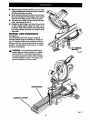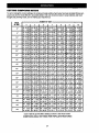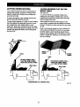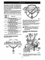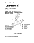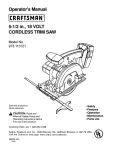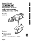
1
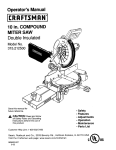
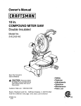
Owner's Manual
10 in. COMPOUND MITER SAW
Double Insulated
Model No.
315.235380
Save this manual for
future reference.
A
CAUTION:
Read and
follow all Safety Rules and
Operating Instructionsbefore
first use of this product.
Customer Help Line
1-800-932-3188
Sears,
Roebuck
and Co.. Hoffman
Visit the Craftsmanweb page: www.sears.com/craftsman
972000-515
4-98
Estates,
IL 60179
USA
NRTL
l
Table of Contents ...................................................................................................
•
Warranty and Introduction ..................................................................
•
Rules For Safe Operation ...........................................................................................................................
•
Glossary ....... :......................................................................................................................................
•
Product Specifications and Unpacking ..............................................................
•
Labels .............................................................................................................................................................
8
•
Loose Parts and Tools Needed ......................................................................................................................
9
•
Features ..................................................................................................................................................
10-12
•
Adjustments ......................................................................................
13-19
•
Operation ................................................
•
Maintenance .................................................................
•
Exploded View and Repair Parts List ......................................................................................................
•
Parts Ordering / Service ...............................................
FULL ONE YEAR WARRANTY
:'.....i ...............................
2
..................... i......................................
2
3-6
........... 6
:...........................................
.......................................................
:..........................................................................
7
i ..................... 20-26
:..........................................................................
:...............................................................................
27-28
30-37
38
ON CRAFTSMAN. COMPOUND MITER SAW
If this I:RNFT$1_IIN Compound Miter Saw fails due to a defect in material or workmanship.within one year from
the date of purchase, Sears will repair it, free of charge.
WARRANTY SERVICE IS AVAILABLE
IN THE UNITED STATES.
BY RETURNING THIS PRODUCT TO THE NEAREST SEARS STORE
This warranty gives you specific legal rights, and you may also have other rights which vary from state to state.
Sears, Roebuck and Co., Dept. 817WA; Hoffman Estates, IL 60179
Your saw has many features for making cutting
operations more pleasant and enjoyable. Safety,
performance and dependability have been given top
priority in the design of this saw making it easy to
maintain and operate.
_1=
,_
Look for this symbol
safety is involved.
to point out important
H
CAUTION: Carefully read through this entire
owner's manual before using your new saw. Pay
close attention to the Rules For Safe Operation,
and all Safety Alert Symbols including Danger,
Warning and Caution. It you use your saw
properly and only for what it is intended, you will
enjoy years of safe, reliable service.
safety precautions.
It means
attention.Vl
Your
WARNING:
The operation of any power tool can result in foreign objects being thrown into your eyes,
which can result in severe eye damage. Before beginning power tool operation, always wear
safety goggles or safety glasses with side shields and a full face shield when needed. We
recommend Wide Vision Safety Mask for use over eyeglasses or standard safety glasses
with side shields, available at Sears Retail Stores.
The purpose of safety symbols is to attract your attention to possible dangers. The safety symbols, and
the explanations with them, deserve your careful attention and understanding. The safety warnings do
not by themselves eliminate any danger. The Instructions or warnings they give are not substitutes for
proper accident prevention measures.
SYMBOL
A
MEANING
SAFETY
ALERT
SYMBOL:
Indicates danger, warning or caution. May be used in conjunction with other symbols or piotographs,
A
DANGER: Failure to obey a safety warning will result in serious injury to yourself or to others.
Always follow the safety precautions to reduce the risk of fire, electric shock and personal injury.
&
WARNING:
Failure to obey a safety warning can result in sedous injury to yourself or to others.
Always follow the safety precautions to reduce the risk of fire, electric shock and personal injury.
A
CAUTION: Failure to obey a safety warning may result in property damage or personal injury to
yourself or to others. Always follow the safety precautions to reduce the risk of fire, electric shock
and personal injury.
NOTE:
Advises you of information or instructions vital to the operation or maintenance of the equipment.
DOUBLE
IMPORTANT
INSULATION
Double insulation is a concept in safety, in electric
power tools, which eliminates the need for the usual
three-wire grounded power cord. All exposed metal
parts are isolated from internal metal motor
components with protecting insulation. Double
insulated tools do not need to be grounded.
A
ALL
INSTRUCTIONS
KEEP GUARDS IN PLACE and in good working
order.
REMOVE ADJUSTING
KEYS AND
WRENCHES.
Get in the habit of checking to see
that hex keys and adjusting wrenches are
removed from tool before turning it on.
ENVIRON-
MENTS. Do not use power tools near gasoline or
other flammable liquids, in damp or wet locations, or expose them to rain. Keep the work
area well lit.
•
KEEP CHILDREN AND VISITORS AWAY. All
visitors should wear safety glasses and be kept a
safe distance from work area. Do not let visitors
contact tool or extension cord while operating.
•
MAKE WORKSHOP CHILD-PROOF
with
padlocks and master switches, or by removing
starter keys.
GUARD AGAINST ELECTRICAL SHOCK BY
PREVENTING BODY CONTACT WITH
GROUNDED SURFACES. For example; pipes,
radiators, ranges, refrigerator enclosures.
•
DO NOT USE IN DANGEROUS
KNOW YOUR POWER TOOL. Read the owner's
manual carefully. Learn the saw's applications
and limitations as well as the specific potential
hazards related to this tool.
m
KEEP THE WORK AREA CLEAN. Cluttered
work areas and work benches invite accidents.
DO NOT leave tools or pieces of wood on the
saw while it is in operation.
WARNING:
Do not attempt to operate this tool
until you have read thoroughly and understand
completely all instructions, safety rules, etc.
contained in this manual. Failure to comply can
result in accidents involving fire, electric shock,
or serious personal injury. Save owner's manual
and review frequently for continuing safe
operation, and instructing others who may use
this tool.
READ
M
Servicing requires extreme care and knowledge of the
system and should be performed only by a qualified
service technician. For service we suggest you return
the tool to your nearest Sears store for repair. Always
use original factory replacement parts when servicing.
•
DO NOT FORCE THE TOOL. It will do the job
better and safer at the rate for which it was
designed.
•
USE THE RIGHT TOOL Do not force the tool or
attachment to do a job it was not designed for.
Don't use it for a purpose not intended.
H
RULES
•.
FOR SAFE
OPERATION
USE THE PROPER ExTENsION
(Continued)
CORD. Make
function. Check for alignment of moving parts,
binding of moving parts, breakage of parts,
mounting and any other conditions that may
affect its operation. A guard or other part that is
damaged must be properly repaired or replaced
by a qualified service technician at a Sears store
to avoid risk of personal injury.
sure your extension cord is in good condition.
When using an extension cord, be sure to use
one heavy enough to carry the current your
product will draw. An undersized cord will cause
a drop in line voltage resulting in loss of power
and overheating: A wire gage size (A.W.G.) of at
least 14 is recommended for an extension cord
NEVER LEAVE TOOL RUNNING UNATTENDED. TURN THE POWER OFF. Do not
leave tool until it comes to a complete stop.
25 feet or less in length. If in doubt, use the next
heavier gage. The smaller the gage number, the
heavier the cord.
•
FIRMLY CLAMP OR BOLT your miter saw to a
workbench or table at approximately hip height.
INSPECT EXTENSION CORDS PERIODICALLY and replace if damaged.
USE ONLY CORRECT BLADES. Do not use
blades with incorrect size holes. Never use blade
washers or blade belts that are defective or
incorrect. The maximum blade capacity of your
saw is 10 in.
DRESS PROPERLY. Do not wear loose clothing,
gloves, neckties, rings, bracelets, or other
jewelry. They can get caught and draw you into
moving parts. Rubber gloves and nonslip footwear are recommended when working outdoors.
Also wear protective hair covering to contain long
hair.
•
•
•
KEEP BLADES CLEAN, SHARP AND WITH
SUFFICIENT SET. Sharp blades minimize
stalling and kickback.
ALWAYS WEAR SAFETY GLASSES WITH
SIDE SHIELDS. Everyday eyeglasses have only
impact-resistant lenses; they are NOT safety
glasses.
PROTECT YOUR LUNGS. Wear a face or dust
mask if the cutting operation is dusty.
DO NOT OVERREACH.
balance at all times.
•
•
. .._ _
•
KEEP HANDS AWAY FROM CUTTING AREA.
Keep hands away from blades. Do not reach
underneath work or around or under the blade
while blade is rotating. Do not attempt to remove
cut material when blade is moving.
Keep proper footing and
MAINTAIN TOOLS WITH CARE. Keep tools
sharp and clean for better and safer performance. Follow instructions for lubricating and
changing accessories.
AVOID ACCIDENTAL
STARTING.
switch is off when plugging in.
•
NEVER STAND ON TOOL. Serious injury could
occur if the tool is tipped or if the blade is unintent'_onally contacted.
WARNING:
•
DO NOT ABUSE CORD. Never yank cord to
disconnect it from receptacle. Keep cord from
heat, oil, and sharp edges.
•
INSPECT TOOL CORDS PERIODICALLY
•
Be sure
USE RECOMMENDED ACCESSORIES. The
use of improper accessories may cause risk of
injury.
A
Blade coasts after turn off.
and if
damaged, have repaired by a qualified service
technician at a Sears store, Stay constantly
aware of cord location and keep it we_laway
from the rotating blade.
DISCONNECT ALL TOOLS. When not in use,
before servicing, or when changing attachments,
blades, bits, cutters, etc., all tools should be
disconnected.
•
•
DO NOT REMOVE THE SAW'S BLADE
GUARDS. Never operate the saw with any guard
or cover removed. Make sure all guards are
operating properly before each use.
PROTECT YOUR HEARING. Wear hearing
protection during extended periods of operation.
SECURE WORK. Use clamps or a vise to hold
work when practical. It's safer than using your
hand and it frees both hands to operate tool.
•
•
USE OUTDOOR EXTENSION CORDS. When
tool is used outdoors, use only extension cords
with approved ground connection that are
intended for use outdoors and so marked.
DO NOT USE TOOL IF SWITCH DOES NOT
TURN IT ON AND OFF. Have defective switches
replaced by a qualified service technician at a
Sears store.
KEEP TOOL DRY, CLEAN, AND FREE FROM
OIL AND GREASE. Always use a clean cloth
when cleaning. Never use brake fluids, gasoline,
petroleumobased products, or any solvents to
clean tool.
CHECK DAMAGED PARTS. Before further use
of the tool, a guard or other part that is damaged
should be carefully checked to determine that it
will operate properly and perform its intended
4
RULES
FOR
SAFE
OPERATION
(Continued)
ALWAYS SUPPORT LONG WORKPIECES to
minimize risk of blade pinching and kickback.
Saw may slip, walk, or slide while cutting long or
heavy boards.
NEVER reach to pick up a workpiece, a piece of
scrap, or anything else that is in or near the
cutting path of the blade.
AVOID AWKWARD OPERATIONS AND HAND
PosmoNs
where a sudden slip could cause
your hand to move into the blade. ALWAYS
make sure you have good balance. NEVER
operate your miter saw on the floor or in a
crouched position.
BEFORE MAKING A CUT, BE SURE ALL
ADJUSTMENTS ARE SECURE.
M
GUARD AGAINST KICKBACK. Kickback occurs
when the blade stalls rapidly and workpiece is
driven back towards the operator. It can pull your
hand into the blade resulting in serious personal
injury. Stay out of blade path and turn switch off
immediately if blade binds or stalls.
•
AVOID CU111NG NAILS, Inspect for and
remove all nails from lumber before cutting.
•
ALWAYS USE A CLAMP to secure the work-
•
ALWAYS release the power switch and allow the
saw blade to stop rotating before raising it out of
the workpiece.
•
DO NOT TURN THE MOTOR SWITCH ON AND
OFF RAPIDLY. This could cause the saw blade
to loosen and could create a hazard. Should this
ever occur, stand clear and allow the saw blade
to come to a complete stop. Disconnect your saw
from the power supply and securely retighten the
blade holt.
to come up to full speed before starting cut.
•
MAKE SURE THE MITER TABLE AND SAW
ARM (BEVEL FUNCTION) ARE LOCKED IN
POSITION BEFORE OPERATING YOUR SAW.
Lock the miter table by securely tightening the
miter lock handle. Lock the saw arm (bevel
function) by securely tightening the bevel lock
knob.
REPLACEMENT PARTS. All repairs, whether
electrical or mechanical, should be made by
qualified service technician at a Sears store.
A
WARNING:
When servicing use only identical
Craftsman replacement parts. Use of any other
parts may create a hazard or cause product
damage.
•
NEVER USE IN AN EXPLOSIVE ATMO-
piece when possible.
•
NEVER TOUCH BLADE or other moving parts
during use.
•
NEVER START A TOOL WHEN THE BLADE IS
IN CONTACT WITH WORKPIECE. Allow motor
•
NEVER stand or have any part of your body in
line with the path of the saw blade.
NEVER USE A LENGTH STOP ON THE FREE
SCRAP END OF A CLAMPED WORKPIECE.
NEVER hold onto or bind the free scrap end of
the workpiece in any operation. If a work clamp
and length stop are used together, they must
both be installed on the same side of the saw
table to prevent the saw from catching the loose
end and kicking up.
SPHERE. Normal sparking of the motor could
ignite fumes.
•
NEVER leave the miter saw unattended while
connected to a power source.
•
POLARIZED PLUGS. To reduce the risk of
electric shock, this tool has a polarized plug (one
blade is wider than the other). This plug will fit in
a polarized outlet only one way. If the plug does
not fit fully in the outlet, reverse the plug. If it still
does not fit, contact a qualified electrician to
install the proper outlet. Do not change the plug
in any way.
•
IF ANY PART OF THIS MITER SAW IS MISS-
NEVER cut more than one piece at a time. DO
NOT STACK more than one workpiece on the
saw table at a time.
NEVER PERFORM ANY OPERATION "FREEHAND". Always place the workpiece to be cat on
the miter table and position it firmly against the
fence as a backstop. Always use the fence.
ING or should break, bend, or fail in any way, or
should any electrical component fail to perform
properly, shut off the power switch, remove the
miter saw plug from the power source and have
damaged, missing, or failed parts replaced
before resuming operation.
NEVER hand .hold a workpiece that is too small
to be clamped. Keep hands clear of the no hands
zone.
NEVER reach behind, under, or within three
inches of the blade and its cutting path with your
hands and fingers for any reason.
•
DO NOT OPERATE THIS TOOL WHILE UNDER THE INFLUENCE OF DRUGS, ALCOHOL,
OR ANY MEDICATION.
RULES
M
FOR SAFE
OPERATION
(Continued)
ALWAYS STAY ALERT! DO not allow familiarity
(gained from frequent use of your saw) to cause
a careless mistake. ALWAYS REMEMBER that
a careless fraction of a second is sufficient to
LIGHTING to see the work and that no obstructions will interfere with safe operation BEFORE
performing any work using your saw.
inflict severe injury.
M
M
STAY ALERT AND EXERCISE CONTROL
Watch what you are doing and use common
sense. Do not operate tool when you are Ured.
Do not rush.
m
ALWAYS TURN OFF SAW before disconnecting
it, to avoid accidental starting when re-connecting to power supply.
m
SAVE THESE INSTRUCTIONS. Refer to them
frequently and use to instruct other users. If you
loan someone this tool, loan them these instructions also.
MAKE SURE THE WORK AREA HAS AMPLE
SAVETHESEINSTRUCTIONS
Set
Arbor
The shaft on which a blade or cutting tool is mounted.
The distance that the tip of the sawblade tooth is bent
(or set) outward from the face of the blade.
Bevel Cut
A cutting operation made with an angled blade.
Throw-Back
Throwihg of a workpiece in a manner similar to a
kickback. Usually associated with a cause other than
the kerf closing, such as a workpiece not being
against the fence, being dropped into the blade, or
being placed inadvertently in contact with the blade.
Crosscut
A cutting or shaping operation made across the grain
of the workpiece.
Compound Miter Cut
A compound miter cut is a cut made using a miter
angle and a bevel angle at the same time.
Through Sawing
Any cutting operation where the blade extends
completely through the thickness of the workpiece.
Freehand
Performing a cut without using a fence, miter gage,
fixture, work clamp, or other proper device to keep the
workpiece from twisting or moving during the cut.
Workplece
The item on which the cutting operation is being'done.
The surfaces of a workpiece are commonly referred to
as faces, ends, and edges.
Gum
A sticky, sap based residue from wood products.
Zero Clearance Throat Plate
A plastic throat plate inserted in the miter table that
allows for blade clearance. When you make your first
cut with your compound miter saw, the saw blade cuts
a slot through the throat plate the exact width of the
blade. This provides for a zero clearance kerr that
minimizes workpiece tear*out.
Miter Cut
A cutting operation made with the blade at any angle
other than 90 degrees.
Resin
A sticky, sap base substance that has hardened.
Revolutions Per Minute (RPM)
The number of turns completed by a spinning object
in one minute.
No Hands Zone
The area between the marked lines on the left and
right side of the miter table base. This zone is
identified by no hands zone labels placed inside the
marked lines on the miter table base.
•-Saw Blade Path
The area over, under, behind, or in front of the blade.
As it applies to the workpiece, that area which will be,
or has been, cut by the blade.
6
Blade Diameter
10 in.
Blade Arbor
Cutting Capacity with Miter at 0°/Bevel 0°:
Maximum Width
5-9/16 in. W x 2-9/32 in. T
5/8 in.
No Load Speed
5000 RPM
Rating
Maximum Thickness
3-9/16 in. T x 4 in. W
120 Volts, 60 Hz-AC Only
Input
15 Amperes
Net Weight
Maximum Cutting Capacity with Miter at 45°/Bevel O°:
46.7 Ibs.
3-15116 in. W x 2-9/32 in. T
Maximum Cuffing Capacity with Miter at 45°/Bevel 45°:
4in. Wx 1-9/16 in, T
Your Compound Miter Saw has been shipped
completely assembled except for the blade, miter lock
handle, and dust guide.
Do not discard the packing materials until you
have carefully inspected the saw, identified all
loose parts, and seUsfactodly operated your new
saw.
_lb
WARNING:
If any parts are missing, do not
operate this tool until the missing parts are
replaced. Failure to do so could result in possible
sedous personal injury.
•
Remove all loose parts from the carton. Separate
and check with the list of loose parts. See Figure 2.
•
Remove the packing
saw.
materials from around your
Carefully lift saw from the carton and place it on a
level work surface. Although small, this sew is
heavy. To avoid back injury, get help when
needed.
•
Your sew has been shipped with the sew arm
locked in the down position. To release sew arm,
push down on top of sew arm and pull out the lock
pin. See Figure 4.
•
Lift the sew arm by the handle. Hand pressure
should remain on the sew arm to prevent sudden
rise upon release of the lock pin.
•
Examine all parts to make sure no breakage or
damage has occurred during shipping.
If any parts are damaged or missing, do not attempt to
plug in the power cord and turn the switch on until the
damaged or missing parts are obtained and are
installed correctly.
The following recommended accessories are currently available at Sears Retail Stores.
•
Miter Saw Clamp (Item No. _929000)
•
Miter Saw Crown Molding Jig (Item No. _929002)
•
Miter Saw Table Extension and Stop Block
(Item No. _9.29001)
•
Miter Saw Oust Bag (item No. 9 23466)
WARNING:
The use of attachments or accessories not listed might be hazardous.
7
The following labels are on the miter saw with locations indicated.
II:RRFTSMRN.
110inch
DOUOLE
INSULATED
RPM
Miter5,000
Saw
120VOLTS
60HzACONLY
15A
CAUTION:ran SAFEOPF.P.AT_,
SEEOWNER'S
MANUAL
WEAR EYE PflOTECTIION.WNENSERVICING, USE ONLYIDENTICAL CRAFTSMAN
REPLACEMENT
PARTS.
MOOEL 315,235300
_i
MAIDE I14 Tll4_lln
SEARS, ROIEBUCKAND CO.
='A't_eN_TOOL
SER. NO.
i
i
I
I
Customer Help Line 1..800-932-3188
ww ewa-fo_:
ADVERTENCIA:
• Rsadownens
manualOniomoparutlng
miter saw Parasuprndleseguddad
• Weareyeprotection,
lea el manualdelusuado
• Keephandsoutofpathofsawblade,
antesdeuserlasierra
• Onnotoperalesawwithoulguardsin place,
iogiotadera.
• DOnotperformanyoperationfreehand.
• Nevermacbaroundthesawblade.
• Tamofftoolandwaltforsawbladefo slop
beforemovingwad(Pieceoruhaqlq ceUIngs.
• Disconnect
thesawfromthe powersourcebefor_
changingbladeor servicing.
iNplaces.
Fig. 1
8
The following items are included with your Compound Miter Saw:
•
Saw Blade - 10 in.
•
5mmHexKey
•
Miter Lock Handle
•
8mmHexKey
•
Dust Guide
•
Owner's Manual
•
Blade Wrench
SAWBLADE
HEXKEY
BLADE
_SmmHEXKEY
_HANDLE
Fig. 2
_kWARNING:
The use of attachments or accessories not listed might be hazardous and could
cause serious personal injury.
The following tools (not included) are needed for
checking adjustments of your saw or for
installing the blade:
,,
,,; @
FRAMINGSQUARE
12 menCOMBINATIONWRENCH
COMBINATION
SQUARE
10 mm COMBINATIONWRENCH
PHILUPSSCREWDRIVER
9
KNOW
YOUR
COMPOUND
MITER
CUTTING
SAW
CAPACITIES
See Figure 3.
When the miter angle (miter table) Is set at 0° and
the bevel angle Is set at 0°:
Before attempting to use your saw, familiarize youmelf
with all operating features and safety requirements.
Your saw will cut materials up to a maximum
width of 5-9/16 in. wide X 2-9/32 in. thick.
_lb
It will cut materials up to a maximum thickness of
3-9/16 in. thick X 4 in. wide.
WARNING:
Do not allow familiadty with your
saw to make you careless. Remember that a
careless fraction of a second is sufficient to inflict
severe injury.
15 AMP
When the miter angle (miter table) Is set at 45 ° and
the bevel angle Is set at O°:
Your saw will cut materials up to a maximum of
3-15/16 in. wide X 2-9/32 in. thick.
MOTOR
Your saw has a powerful 15 amp motor with sufficient
power to handle tough cutting jobs. It is made with all
ball beadngs, and has externally accessible brushes
for ease of servicing.
10 in. BLADE
A 10 in. saw blade is included with your compound
miter saw. It will cut materials up to 3-9/16 in. thick or
5-9/16 wide, depending upon the thickness of the
material and the setting at which the cut is being
made.
When the miter angle (miter table) Is set at O° and
the bevel angle Is set at 45°:
Your saw will cut materials up to a maximum of
5-9116 in. wide X 1-9116 in. thick.
When the miter angle (mRer table) is set at 45 ° and
the bevel angle ia set at 45°:
Your saw will cut materials up to a maximum of
4 in. wide X 1-9/16 in. thick.
SAW ARM
SWITCH
UPPER
BLADEGUARD
DUSTGUIDE
LOWER
BLADEGUARD
MITERTABLE
BEVEL
NO HANDS
ZONELABEL
BEVELSCALE.
"NO HANDSZONE"
BOUNDARYUNE
MITERSCALE
ZEROCLEARANCE
THROATPLATE
MITER
LOCKpLaTE
MITER
CONTROLARM
POSmVE STOP(S)
10
MITER
LOCKHANDLE
Fig. 3
CARRYING
HANDLE
SPINDLE
LOCK
BUTTON
See Figure 4.
See Figure 5.
For convenience when carrying or transporting your
miter saw from one place to another, a carrying
handle has been provided on top of the saw arm as
shown in figure 4. To transport, tam off and unplug
your saw, then lower the saw arm and lock it in the
down position. Lock saw arm by depressing the lock
pin.
A spindle lock button has been provided for locking
the spindle which stops the rotation of the blade in
your saw. Depress and hold the lock buttOnwhile
installing, changing, or removing blade.
SPINDLELOCKBUTTON
CARRYING
HANDLE
LOCK-OFF
LEVER"
SAW
ARM
LOCK
PIN
Fig. 5
TRIGGER
MITER LOCK
HANDLE
SAW ARM
LOCKEDIN DOWNPOSITION
MITER
LOCK
To prevent unauthorized use of your compound miter
saw, we suggest that you disconnect it from the power
supply and lock the switch in the off position. To lock
the switch, install a padlock through the hole in the
switch trigger. A lock with a shackle up to 13164 in.
(5 ram) diameter may be used. When the lock is
installed and locked, the switch is inoperable• Store
the padlock key in another location.
Fig. 4
HANDLE
See Figure 4.
The miter lock handle securely locks your saw at
desired miter angles.
LOCK-OFF
LOCK
See Figure 6.
LEVER
See Figure 5.
The switch trigger is equipped with a lock-off lever to
reduce the possibility of accidental starting. The lockoff lever must be slid back away from the switch
"_trigger in order to turn saw on. Once the saw is on,
the lock-off lever can be released. The spring loaded
lever will spring back into the lock-off position when
the switch trigger is released.
SWITCH
TRIGGER
Fig. 6
11
POSITIVE
STOPS
ON MITER
TABLE
Positive stops have been provided at 0°, 22-1/2 °,
31.6 °, and 45 °. The 22-1/2 °, 31.6 °, and 45 ° positive
stops have been provided on both the left and right
side of the miter table.
BEVEL
LOCK
KNOB
The bevel lock knob securely locks your compound
miter saw at desired bevel angles. Positive stop
adjustment screws have been provided on each side
of the saw arm. These adjustment screws are for
making fine adjustments at 0 ° and 45 °. See pages 17
and 18.
.ELECTRIC
BRAKE
An electric brake has been provided to quickly stop
blade rotation after the switch is released.
Fig. 7
FENCE
ELECTRICAL
The fence on your compound miter sew has been
provided to hold your workpiece securely against
when making all cuts.
Your saw has a precision built electric motor. It should
be connected to a power supply that is 120 volts,
60 Hz, AC only (normal household current). Do not
operate this tool on direct current (DC). A substantial
voltage drop will cause a loss of power and the motor
will overheat. If your tool does not operate when
plugged into an outlet, double-check the power
supply.
SELF-RETRACTING
GUARD
LOWER
BLADE
The lower blade guard is made of shock-resistant,
see-through plastic that provides protection from each
side of the blade. It retracts over the upper blade
guard as the saw is lowered into the workpiece.
MOUNTING
_h
HOLES
See Figure 7.
Your compound miter saw should be permanently
mounted to a firm Supporting surface such as
workbench. Four 3/8 in. bolt holes have been
provided in the saw base for this purpose. Each of
the four mounting holes should be bolted securely
using 318 in. machine bolts, lock washers, and hex
nuts (not included). Bolts should be of sufficient
length to accommodate the saw base, lock washers,
hex nuts, and the thickness of the workbench.
WARNING: The operation of any saw can
result in foreign objects being thrown into your
eyes, which can result in severe eye damage.
Before starting power tool operation, always
wear safety goggles or safety glasses with side
shields and a full face shield when needed. We
recommend wide vision safety mask for use over
eyeglasses or standard safety glasses with side
shields.
_k
Tighten all four bolts securely.
The hole pattern for an 18 in. x 24 in. workbench is
shown in Figure 7. Carefully check the workbench
after mounting to make sure that no movement can
-occur during use. If any tipping, sliding, or walking is
noted, secure the workbench to the floor before
operating.
_,
CONNECTION
WARNING:
Always make sure your compound
miter saw is securely mounted to a workbench or
an approved workstand. Failure to do so could
result in an accident resulting in possible serious
personal injury.
12
WARNING: Do not attempt to modify this tool or
create accessories not recommended for use
with this tool. Any such alteration or modification
is misuse and could result in a hazardous
condition leading to possible serious personal
injury.
_
WARNING:
To prevent accidental starting that
could cause possible serious personal injury,
assemble all parts to your saw before connecting
it to power supply. Saw should never be
connected to power supply when you are
assembling parts, making adjustments, installing
or removing blades, or when not in use.
TO
LOCK
WARNING:
A 10 in. blade is the maximum
blade capacity of your saw, Never use a blade
that is too thick to allow outer blade washer to
engage with the fiats on the spindle. Larger
blades will come in contact with the b/ade
guards, while thicker blades will prevent the
blade screw from securing the blade on the
spindle. Either of these situations could result in
a serious accident and can cause serious
personal injury.
HANDLE
See Figure 8.
To install the miter lock handle, place the threaded
stud on the end of the miter lock handle into the
threaded hole in the control arm. Turn clockwise to
BLADE
See Figures 10, 11, and 12.
As mentioned previously your saw has been factory
assembled and adjusted. The miter lock handle, dust
guide, and blade are the only parts that have to be
installed.
MITER
INSTALL
I=
Unplug your saw.
WARNING: Failure to unplug your saw could
result in accidental starting causing possible
serious personal injury.
tighten.
Push down on the sew arm and pull out the lock
pin to release sew arm. Raise sew arm to its full
raised position. Be cautious, saw arm is spring
loaded to raise.
Loosen the phillips screw on the blade bolt
cover until blade bolt cover can be raised.
See Figures 10 and 11.
Gently raise the lower blade guard bracket,
releasing lower blade guard from notch so that
lower blade guard and blade bolt cover can be
rotated up and back to expose the blade bolt. See
Figures 10 and 11.
TIGHTEN
MITER
LOCKHANDLE
ARM
MITER
TABLE
Fig. 8
DUST
GUIDE
See Figure 9.
To install the dust guide, place the end marked
INSERT over the exhaust port in the upper blade
guard. Turn the guide so that the open end is facing
down Or toward the rear of the saw.
LOWER
BLADEGUARD
EXHAUST
PORT
NOTCH
LOWERBLADE
DUSTGUIDE
Fig. 10
Fig. 9
13
•
LOWER
BLADEGUARD
Wipe a drop of oil onto inner blade washer and
outer blade washer where they contact the blade.
WARNING:
If inner blade washer has been
removed, replace it before placing blade on
spindle. Failure to do so could cause an accident
since blade will not tighten properly.
PhILMPS
SCREW
BLADE
BOLTCOVER
•
FLAT($)
ON SPINDLE
CAUTION: Always install the blade with the
blade teeth and the arrow printed on the side of
the blade pointing down at the front of the saw.
The direction of blade rotation is also stamped
with an arrow on the upper blade guard.
INNERBLADE
DOUBLE"D"
FLATS
TO
LOOSEN
BLADE
TIGHTEN
•
Replace outer blade washer. The double "D" fiats
on the blade washers align with the flats on the
spindle.
•
Depress spindle lock button and replace blade
bolt.
OUTERBLADEWASHER
WITH DOUBLE"D" FLATS
Note: The blade bolt has left hand threads. Turn
blade bolt couotemlockwise to tighten.
BLADEBOLT
•
Tighten blade bolt securely.
•
Depress the spindle lock button and rotate the
blade bolt until the spindle locks. See Figure 12.
Remove the blade wrench and store it in a safe
place for future use.
•
Using the blade wrench provided, loosen and
remove the blade bolt.
Replace the lower blade guard and blade bolt
cover.
•
Retighten phillips screw securing blade bolt cover.
Tighten screw securely. See Figure 11.
Fig. 11
•
•
Note: The blade bolt has left hand threads. Turn
blade bolt clockwise to loosen.
•
Fit saw blade inside lower blade guard and onto
spindle. The blade teeth point downward at the
front of saw as shown in figure 11.
WARNING: Make sure the spindle lock button is
not engaged before reconnecting sew into power
source. Never engage spindle lock button when
blade is rotating.
Remove outer blade washer. Do not remove
inner blade washer.
Your compound miter saw has been adjusted at the
factory for making very accurate cuts. However, some
of the components might have been jarred out of
alignment during shipping. Also, over a period of time,
readjustment will probably become necessary due to
wear. After unpacking your saw, check the following
adjustments before you begin using saw. Make any
readjustments that are necessary and periodically
check the parts alignment to make sure that your saw
is cutting accurately.
SPINDLE
LOCK
BUTTON,
,4_
Fig. 12
14
WARNING:
Your saw should never be
connected to power supply when you are
assembling parts, making adjustments, installing
or removing blades, or when not in use.
Disconnecting your saw will prevent accidental
starting that could cause serious injury.
Note: Many of the illustrations in this manual show
only portions of your compound miter saw. This is
intentional so that we can dearly show points being
made in the illustrations. Never operate your saw
without all guards securely in place and in good
operating condition.
FENCE I\
I1_
J_RTABLE
\
CUTTING A SLOT IN THE ZERO
CLEARANCE THROAT PLATE
In order to use your compound miter saw, you must
cut a slot through the zero clearance throat plate to
allow for blade clearance. To cut the slot, set your
saw at 0 degrees miter, turn saw on and allow the
blade to reach full speed, then carefully make a
straight cut as far as it will go through the throat plate.
Turn your saw off and allow the blade to come to a
complete stop before raising the saw arm.
LOCKPLATE
VIEWOFMITERTABLESQUAREWITH FENCE
Next, adjust the bevel angle to 45 degrees, turn your
saw on and allow the blade to reach full speed, then
carefully make another cut through the zero clearance
throat plate. The throat plate will then be wide enough
to allow the blade to pass through it at any angle from
0 to 45 degrees.
SQUARING
TO
THE
THE
MITER
LOCKHANDLE
ANDCORRECTLYADJUSTED
FENCE
Fig. 13
MITERTABLE
TABLE
FENCE
See Figures 13 - 16.
•
_IL
Unplug your saw.
WARNING: Failure to unplug your saw could
result in accidental starting causing possible
serious personal injury.
•
Push down on the saw arm and pull out the lock
pin to release the saw arm.
•
Raise saw arm to its full raised position.
•
Loosen the miter lock handle approximately onehalf turn.
•
Depress the miter lock plate and rotate the miter
table until the pointer on the control arm is positioned at 0°.
•
Release the miter lock plate and securely tighten
the miter lock handle.
•
Lay a framing square flat on the miter table. Place
one leg of the square against the fence. Place the
other leg of the square beside the zero clearance
throat plate in the miter table. The edge of the
square and the zero clearance throat plate in
the miter table should be parallel as shown in
figure 13.
•
If the edge of the framing square and the zero
clearance throat plate in the miter table are not
parallel as shown in figures 14 and 15, adjustments are needed.
FRAMING
SQUARE
ZEROCLEARANCE
THROATPLATE
VIEW OFMITERTABLENOT SQUAREWITH
FENCE,ADJUSTMENTSARE REQUIRED
Fig. 14
FENCE
FRAMING
SQUARE
MITERTABLE
ZEROCLEARANCE
THROATPLATE
VIEW OF MITER TABLE NOT SQUARE WITH
FENCE, ADJUSTMENTS ARE REQUIRED
15
Fig. 15
•
Using a 12 mm wrench or adjustable wrench,
loosen the hex head bolts located under the miter
FENCE
table. See Figure 16. Adjust the miter table left or
right until the framing square and zero clearance
throat plate are parallel.
•
Retighten the screws securely and recheck the
fence-to-table alignment.
MITER
MITER
PLATE
TABLE
FRAMING
SQUARE
VIEWOFBLADE
SQUAREWITHFENCE
bMITER
LOCK HANDLE
Fig. 17
FENCE
HEX BOLT(S)
BOTTOMVIEW OFMIrrERTABLE
SQUARING
THE
SAW
BLADE
Fig. 16
TO
THE
FENCE
BLADE
See Figures 17 o 20.
•
_L
Pull the saw arm all the way down and engage
the lock pin to hold the saw arm in transport
position.
•
Loosen the miter lock handle approximately
one-half turn.
•
Depress the miter lock plate and rotate the miter
table until the pointer on the control arm is
positioned at 0 °
•
FRAMING
SQUARE
WARNING: Failure to unplug your saw could
result in accidental starting causing possible
serious personal injury.
•
-•
MITER
TABLE
Unplug your saw.
VIEWOF BLADENOT SQUAREWITH
FENCE,ADJUSTMENTSAREREQUIRED
Fig. 18
FENCE
- Release the miter lock plate and securely tighten
the miter lock handle.
Lay a framing _uare fiat on the miter table. Place
one leg of the square against the fence. Slide the
other leg of the square against the fiat part of saw
blade.
BLADE
MITER
TABLE
Note: Make sure that the square contacts the flat
part of the saw blade, not the blade teeth.
FRAMING
SQUARE
VIEW OF BLADE NOT SQUARE WITH
FENCE, ADJUSTMENTS ARE REQUIRED
Fig. 19
16
I
The edge of the square end the sew blade should
be parallel as shown in figure 17.
•
If the front or back edge of the saw blade angles
away from the square as shown in figures 18 and
19, adjustments are needed.
Loosen bevel lock knob and set sew arm at 0=
bevel (blade set 90 ° to miter table). Tighten bevel
lock knob.
•
Using the 8 mm hex key provided, loosen the
socket head screws that secure the mounting
bracket to the miter table. See Figure 20.
Place a combination square against the miter
table and the fiat part of sew blade.
Note: Make sure that the square contacts the fiat
part of the saw blade, not the blade teeth.
•
Rotate the blade by hand and check the blade-totable alignment at several points,
•
The edge of the square and the sew blade should
be parallel as shown in figure 21.
FENCE
8 nlm SOCKET
HEADSCREW(S)
BLADE
8 mm HEXKEY
MITER
TABLE
TABLE
F
MITER
MOUNTING
BRACKET
COMBINATION
SQUARE
LOCKHANDLE
Fig. 20
•
Rotate the mounting bracket left or right until the
saw blade is parallel with the square.
•
Retighten the screws securely and recheck the
blade-to-fence alignment.
SQUARING
MITER
THE
BLADE
TO
CORRECT VIEW OF BLADE
SQUARE WITH MITER TABLE
Fig. 21
If the top or bottom of the saw blade angles away
from the square as shown in figures 22 and 23,
adjustments are needed.
THE
TABLE
FENCE
See Figures 21 - 24.
•
&
MITER
LOCK
PLATE
Unplug your sew.
WARNING: Failure to unplug your saw could
result in accidental starting causing possible
serious personal injury.
•
Pull the sew arm all the way down and engage
the lock pin to hold the saw arm in transport
position.
•
Loosen the miter lock handle approximately onehalf turn.
•
Depress the miter lock plate and rotate the miter
table until the pointer on the control arm is positioned at 0 °
•
Release the miter lock plate and securely tighten
the miter lock handle.
TABLE
COMBINATION
SQUARE
VIEWOF BLADENOT SQUAREWITHMITER
TABLE,ADJUSTMENTSAREREQUIRED
Fig. 22
17
PIVOT
ADJUSTMENTS
Note: These adjustments were made at the factory
and normally do not require readjustment.
TRAVEL
•
If the sew arm does not raise by itself or if there is
play in the pivot joints, have sew repaired by a
qualified service technician at a Sears store to
avoid risk of personal injury.
BEVEL
VIEWOF BLADENOT SQUAREWITH MITER
TABLE,ADJUSTMENTSARE REQUIRED
Adjust positive stop adjustment screw to bring
saw blade into alignment with the square. See
Figure 24.
PIVOT
ADJUSTMENT
BI
Your compound miter saw should bevel easily by
loosening the bevel lock knob and tilting the sew
arm to the left.
•
If movement is tight or if there is play in the pivot,
have saw repaired by a qualified service technician at your nearest Sears store.
Fig. 23
Using a 10 mm wrench or adjustable wrench,
loosen the lock nut securing positive stop adjustment screw. Also loosen bevel lock knob.
ADJUSTMENT
The saw arm should rise completely to the up
position by itself.
BLADE
TABLE
COMBINATION
SQUARE
PIVOT
DEPTH
STOP
The depth stop limits the blade's downward travel. It
allows the blade to go below the miter table enough to
maintain full cutting capacities. The depth stop
positions the blade 1/4 in. from the miter table support.
Note" The miter table support is located inside miter
table.
The depth stop is factory set to provide maximum
cutting capacity for the 10 in. saw blade provided with
your saw. Therefore, the saw blade provided should
never need adjustments.
However, when the diameter of the blade has been
reduced due to sharpening, it may be necessary to
adjust the depth stop to provide maximum cutting
capacity. Also, when a new blade is installed, it is
necessary to check the clearance of the blade to the
miter table support before starting the saw. Make
adjustments if needed.
POSITIVESTOP
ADJUSTMENT
SCRE• FOR
4S° ANGLES
DEPTH
STOP
ADJUSTMENTS
See Figure 25.
•
A
Unplug your saw.
WARNING: Failure to unplug your saw could
result in accidental starting causing possible
serious personal injury.
Fig. 24
BI To adjust the depth stop use a 17 mm wrench or
adjustable wrench and loosen the hex nut at the
rear of the miter saw arm.
Retighten bevel lock knob. Next, retighten lock nut
securing the positive stop adjustment screw.
Recheck blade-to-table alignment.
Use the 5 mm hex key provided to adjust the
depth stop adjustment screw. The saw blade is
lowered by turning the screw counter-clockwise
and raised by turning the screw clockwise.
Note: The above procedure can be used to check
blade squareness of the saw blade to the miter
table at beth 0 ° and 45 ° angles.
18
DEPTH
STOP
ADJUSTMENT
SCREW
_k
BEVEL
LOCKKNOB
WARNING:
Before starting any cuffing
operation, clamp or bolt your compound miter
saw to a workbench. Never operate your miter
saw on the floor or in a crouched position.
Failure to heed this warning can result in serious
personal injury.
CUTTING WITH YOUR COMPOUND
MITER SAW
A
MITER
TABLE
LOCK
WARNING:
When using a work clamp or
C-clamp to secure your workpiece, clamp
workpiece on one side of the blade only. The
workpiece must remain free on one side of the
blade to prevent the blade from binding in
workpiece. The workpiece binding the blade will
cause motor stalling and kickback. This situation
could cause an accident resulting in possible
serious personal injury.
CROSSCUTTING
POSITIVE
STOPADJUSTMENT
SCREWFOR 0° ANGLES
•
See Figure 26.
Fig. 25
Lower the blade into the zero clearance throat
plate of the miter table. Check blade clearance
and maximum cutting distance (distance from
fence where blade enters) to front of miter table
slot.
•
A crosscut is made by cutting across the grain of the
workpiece. A straight crosscut Js made with the miter
table set at the zero degree position. Miter crosscuts
are made with the miter table set at some angle other
than zero.
TO CROSSCUT
WITH
YOUR
MITER
SAW:
•
Pull out the lock pin and lift saw arm to its full
height,
•
Loosen the miter lock handle, Rotate the miter
lock handle approximately one-half turn to the left
to iooson,
table support during operation of the saw.
•
Press the miter lock plate down with your thumb
and hold.
•
Tighten the hex nut with a 17 mm wrench or
adjustable wrench.
•
Rotate the control arm until the pointer aligns with
the desired angle on the miter scale.
•
To prevent the depth stop adjustment screw from
turning while tightening the hex nut, carefully hold
it with the hex key while tightening the hex nut.
•
Release the miter lock plate.
_k
Readjust if necessary.
WARNING:
Do not start your compound miter
saw without checking for interference between
the blade and the miter table support. Damage
could result to the blade if it strikes the miter
Note: You can quickly lecate 0 °, 22-1/2 ° left or
right, 31,6 ° left or right, and 45 ° left or right by
releasing the lock plate as you rotate the control
arm. The lock plate will seat itself in one of the
positive stop notches, located in the miter table
frame.
APPLICATIONS
•":(Use only for the purposes listed below)
•
Cross cutting weed and plastic.
•
Cross cutting miters, joints, etc. for picture frames,
moldings, door casings, and fine joinery.
•
Note: The 104 tooth crosscut blade provided is fine
for most wood cutting operations, but for fine joinery
cuts or cutting plastic, use one of the accessory
blades available from your nearest Sears store.
Tighten the miter lock handle securely.
_1= WARNING: To avoid serious personal injury,
always tighten the miter lock handle securely
before making a cut. Failure to do so could result
in movement of the control arm or miter table
while making a cut.
19
Slowly lower the blade into and through the
workpiece. See Figure 26.
Release the switch trigger and allow the saw
blade to stop rotating before raising the blade out
of workpiece, Wait until the electric brake stops
blade from turning before removing the workpiece
from the miter table.
STRAIGHT
CROSSCUT
BEVEL
CUT
See Figures 27 and 28.
A bevel cut is made by cutting across the grain of the
workpiece with the blade angled to the workpieca. A
straight bevel out is made with the miter table set at
the zero degree position and the blade set at an angle
between 0 ° and 45 °.
LEFTSiDE
RIGHTSIDE
RIGHT
INDICATOR
POINT
LEFT
INDICATOR
POINT
Fig. 26
Place the workpiece flat on the miter table with
one edge securely against the fence. If the board
is warped, place the convex side against the
fence. If the concave edge of a board is placed
against the fence, the hoard could collapse on the
blade at the end of the cut, jamming the blade.
See Figures 33 and 34.
SCALE
SCALE
MOUNTINGBRACKET
TO BEVEL
SAW:
When cutting long pieces of lumber or molding,
support the opposite end of the stock with a roller
stand or with a work surface level with the saw
table.
•
Grasp the saw handle firmly, slide the lock-off
lever back, then Squeeze the switch trigger. Allow
several seconds for the blade to reach maximum
speed.
MITER
Press the miter lock plate down with your thumb
and hold.
Rotate the control arm until the pointer aligns with
zero on the miter scale.
WARNING: To avoid serious personal injury,
keep your hands outside the no hands zone; at
least 3 in. from blade. Never perform any cutting
operation freehand (without holding workpiece
against the fence). The blade could grab the
workpiece if it slips or twists.
Before turning on the saw, perform a dry run of the
cutting operation just to make sure that no
problems will occur when the cut is made.
YOUR
Loosen the miter lock handle. Rotate the miter
lock handle approximately one-half turn to the left
to loosen.
Grasp the stock firmly with one hand and secure
it against the fence. Use the optional work clamp
or a C-clamp to secure the workpiece when
possible. See Figure 26.
•
WITH
Pull out the lock pin and lift saw arm to its full
height.
Align cutting line on the workpiece with the edge
of saw blade.
_- -
CUT
Fig. 27
Release the miter lock plate.
Note: You can quickly locate zero by releasing
the lock plate as you rotate the control arm. The
lock plate will seat itself in one of the built4n
positive stop notches, located in the miter table
frame.
•
,_
20
Tighten the miter lock handle securely.
WARNING:
To avoid serious personal injury,
always tighten the miter lock handle securely
before making a cut. Failure to do so could result
in movement of the control arm or miter table
while making a cut.
_._ WARNING: To avoid serious personal injury,
keep your hands outside the no hands zone; at
least 3 in. from blade. Never perform any cuffing
operation freehand (without holding workpiece
against the fence). The blade could grab the
workpiece if it slips or twists.
•
Before turning on the saw, perform a dry run of
the cutting operation just to make sure that no
problems will occur when the cut is made.
•
Grasp the saw handle firmly, slide the lock-off
lever back, then squeeze the switch trigger. Allow
several seconds for the blade to reach maximum
speed.
C-CLAMP
Fig. 28
mm Loosen the bevel lock knob and move the saw
arm to the left to the desired bevel angle.
•
•
Place the workpiece fiat on the miter table with
one edge securely against the fence. If the board
is warped, place the convex side against the
fence. If the concave edge of a board is placed
against the fence, the board could collapse on the
blade at the end of the cut, jamming the blade.
See Figures 33 and 34.
•
J
•
•
Release the switch trigger and allow the saw
blade to stop rotating before raising the blade out
of workpiece. Wait until the electric brake stops
blade from turning before removing the workpiece
from miter table.
MITER
CUT
A compound miter cut is a cut made using a miter
angle and a bevel angle at the same time, This type of
cut is used to make picture frames, cut molding, make
boxes with sloping sides, and for certain roof framing
mm For your convenience there is a double scale
located on the mounting bracket. See Fig'ure 27. If
one side becomes difficult to read as you move
the saw arm to the left, simply refer to the other
side. Align the indicator point for the side you
choose with the desired angle.
Once the saw arm has been set at the desired
angle, securely tighten the bevel lock knob.
Slowly lower the blade into and through the
workpiece. See Figure 28.
COMPOUND
Bevel angles can be sat from 0 ° to 45 °.
•
•
To make this type of cut the control arm on the miter
table must be rotated to the correct angle and the saw
arm must be tilted to the correct bevel angle. Care
should always be taken when making compound miter
setups
cuts. due to the interaction of the two angle settings.
Adjustments of miter and bevel settings are interdependent with one another. Each time you adjust the
miter saffing you change the effect of the bevel
setting. Also, each time you adjust the bevel setting
you change the effect of the miter setting.
It may take several settings to obtain the desired cut.
The first angle setting should be checked after satting
the second angle, since adjusting the second angle
affects the first.
When cutting long pieces of lumber or molding,
support the opposite end of the stock with a roller
stand or with a work surface level with the saw
table.
Once the two correct settings for a particular cut have
been obtained, always make a test cut in scrap
material before making a finish cut in good material.
Align the cutting line on the workpiece with the
edge of saw blade.
Grasp the stock firmly with one hand and secure it
against the fence. Use the optional work clamp or
a C-clamp to secure the workpiece when possible. See Figure 28.
21
H
TO MAKE A COMPOUND
YOUR MITER SAW:
CUT WlTH
•
Place the workpiece fiat on the miter table with
one edge securely against the fence. If the board
is warped, place the convex side against the
fence. If the concave edge of a board is placed
against the fence, the board could collapse on the
blade at the end of the cut, jamming the blade.
See Figures 33 and 34.
•
When cuffing long pieces of lumber or molding,
support the opposite end of the stock with a roller
stand or with a work surface level with the saw
table.
Pull out the lock pin and lift sew arm to its _lJheight.
Loosen the miter lock handle. Rotate the-miter
lock handle approximately one-half turn to the left
to loosen.
•
Press the miter lock plate down with your thumb
and hold.
•
Rotate the control arm until the pointer aligns with
the desired angle on the miter scale.
•
Release the miter lock plate.
Align the cuffing line on the workpiece with the
edge of sew blade.
Note: You can quickly locate 0 =, 22-1/2° left or
right, 31.6 ° left or right, and 45 ° left or right by
releasing the miter lock plate as you rotate the
control arm. The miter lock plate will seat itself in
one of the positive stop notches, located in miter
table frame.
•
_lb
Grasp the stock firmly with one hand and secure it
against the fence. Use the optional work clamp or
a C-clamp to secure the workpiece when possible. See Figure 29.
,_
Tighten the miter lock handle securely.
WARNING:
To avoid serious personal injury,
always tighten the miter lock handle securely
before making a cut. Failure to do so could result
in movement of the control arm or miter table
WARNING: To avoid serious personal injury,
always keep your hands outside the no hands
zone; at least 3 in. from blade. Never perform
any cutting operation freehand (without holding
workpiece against the fence). The blade could
grab the workpisce if it slips or twists.
while making a cut.
COMPOUND
MITERCUT
Loosen the bevel lock knob and move the sew
arm to the left to the desired bevel angle.
Bevel angles can be set from 0 ° to 45 °.
For your convenience there is a double scale
located on the mounting bracket. See Figure 27. If
one side becomes difficult to read as you move
the sew arm to the left, simply refer to the other
side. Align the indicator point for the side you
choose with the desired angle.
Once the sew arm has been set at the desired
angle, securely tighten the bevel lock knob.
Recheck miter angle setting. Make a test cut in
scrap material.
,C-CLAMP
22
Fig. 2_J
•
•
•
•
Befora tuming on the saw, perform a dry run of the
cutting operation just to make sure that no problems
will occur when the cut is made.
Grasp the saw handle firmly, slide the lock-off lever
back, then squeeze the switch bigger. Allow several
seconds for the blade to reach maximum speed.
Slowly lower the Made into and through the workI_ece. See Figures 29 and 30.
Release the switch trigger and allow the saw blade
to stop rotating before raising the Made out of
workpiece. Wait until the electric brake stops blade
from turning before removing the workpiece from
miter tame.
SUPPORT
LONG
WORKPIECES
" See Figure 31.
Long workpieces need extra supports. Supports
should be placed along the workpiece so it does not
sag. The support should let the workpiece lay flat on
the base of the saw and work table during the cutting
operation. Usa the optional work clamp or a C-clamp
to secure the workplace.
45° X 4S° COMPOUND
iI1ER CUT
WARNING:
To avoid serious personal injury,
always keep your hands outside the no hands
zone; at least 3 in. from blade. Never perform
any cutting operation freehand (without holding
workpiece against the fence). The blade could
grab the workpiece if it slips or twists.
Fig. 30
LONGWORKRECE
WORKPIECE SUPPORTS
Fig. 31
23
CUTTING
COMPOUND
MITERS
-,
_
,.
To aid in making the correct settings, the compound angle setting chart below has been provided. _ince compound cuts are the most difficult to accurately obtain, trial cuts should be made in scrap material, _nd much
thought and planning made, prior to making your required cut.
PITCH
NUMBEROF SIDES
OFSIDE
4
I
5
I
6
I
0=
M- 45.00 ° M- 36.00 ° M- 30.00 =
B- 0.00 ° B. 0.00 = B- 0.00 °
5°
M- 44.89 o M-35,90 °
13- 3.53 °
M- 44.56 °
B- 7.05 °
......
7
I
8
i
i
I
9
10
M- 25.71 °
B. 0.00 =
M- 22.50 °
B- 0'.00_
M- 20.00 ° "M- 18o00°
B- 0.000 B- 0.00 °
M-29.91 =
M-25.63 °
M-22.42 °
M-19.93_M-17.94
B- 2.94 °
M- 35.58 =
B- 5.86 °
B- 2.50 °
M- 29,62 =
13- 4.98 °
B- 2.17 =
M- 25,37 =
B- 4.32 °
13- 1.91 °
M- 22.19 °
B- 3.81 °
B- 1.71 ° i B- 1.54"
M- 19,72 =_'IM- 17.74 °
13- 3.40 ° !B- 3.08 °
M-44.01 °
B-10.55 °
M-35.06 °
B. 8.75 °
M-29.15 =
B. 7.44 °
M-24.95 =
B- 6.45 °
M-21,81 °
B- 5.68 °
M-19.37 G !M-17.42 °
13- 5.08 = !13- 4.59 °
M-43,22 °
M-34.32 =
M-28.48 °
M-24.35 °
M-21.27 = M- 18.8_,_' M- 16.98 °
B-14.00 °
M-42.19 °
B. 17.39 °
B.11.60 =
M-33.36 °
B- 14.38 °
B. 9.85 °
M-27.62 °
B. 12.20 =
B- 8.53 °
M-23.56 °
3- 10.57 °
B- 7.52" B. 6.72 = B- 6.07 =
M-20,58 = M- 1_i_6 = M- 16.41 °
B- 9.31 ° _.- 8.31 ° IB. 7.50 °
30 °
M-40.89 °
B-20,70 =
M-32.18 o
B.17.09 =
M-26.57 o
13-14,48 =
M-22.64 o
13-12.53 =
M-19.73 o "_-_17_50= M. 15.72 o
B-11.03 ° B. 9,85 ° !B- 8.69 °
35 °
M-39.32 °
13-23,93 °
M-30.76 °
B- 19,70 °
M-25.31 °
B- 16.67 °
M-21.53 °
13-14,41 °
M-18.74 = M-_'16.60°
13-12.68 = B. tl.31 °
40 °
M-37.45 ° M- 29.10 °
B- 27.03 ° B. 22,20 °
M- 23.66 °
B. 18,75 °
M- 20.25 °
B- 16.19 °
M- 17.60 °
B. 14.24 °
45 °
M-35.26 ° M- 27.19 °
B. 30.00 =' B. 24,56 °
M-22.21 °
B- 20.70 °
M- 18.80 °
13-17.87 °
M- 16.32 °
B. 15.70 °
M- 14.43 °
B- 14.00 °
M- 12.94 =
B- 12.62 °
M-32.73 °
B. 32.80 °
M-25.03 °
13-26,76 °
M-20.36 °
B- 22.52 °
M-17.20 °
13-19.41 =
M-14.91 °
13-17.05 °
M-13.17 =
13-15.19 °
M-11.80 =
B. 13.69 °
55 °
M-29.84 °
B- 35.40 °
M-22.62 °
B- 28.78 °
M-18.32 °
B- 24.18 °
M-15.44 °
B- 20,82 °
M-13.36 = M-11.79 °
13- 18.27 ° B- 16.27 °
M-10.56 °
B. 14.66 °
60 °
VI-26.57 °
B- 37.76 °
M-19.960
B- 30,60 °
M-16.10 °
B- 25,66 °
M-13.54 °
B- 22.07 °
M-11.70 = M-10.31 = M- 9.23 °
B. 19.35 ° 13-17.23 ° 13-15.52 °
M-13.71 °
B- 26.95 °
M-11.50 =
B.23.16 °
M- 9.93 °
B- 20.29 =
M-18.88 ° IM-13.95 = IM-11.17 °
: B- 41,64 ° i B- 33.53 ° B- 28.02 °
M- 9.35 °
B. 24,06 °
M- 8.06 °
B- 21.08 °
i
10=
15°
20 °
25 °
=
I
M. 14.90 °
B. 10.21 °
I
i
50°
M- 15.58 = M- 13.98 °
B. 12.70 ° B- 11.46 °
I
I
L
65°
!M-22.91 ° _M-17.07 =
B. 39.86 ° 13-32,19 =
III
70 °
75 °
80 °
85°
90 °
M- 8.74 °
B- 18.06 =
M- 7.82 °
B-16.26 =
M- 7.10 °
13"18.75 °
M- 6.34 °
13-16.88 °
I
M-14.51 °
B-43.08 °
M- 9.85 °
B- 44.14 °
M-10.65 °
B-34.59 °
M- 7.19 °
13-35.37 °
M- 8.50 ° M" 7-10 ° M- 6.12 ° M- 5.38 °
B- 28.88 ° 13"24.78 °
13-21.69 ° B" 19.29 °
M- 5.73 ° M- 4.78°
M- 4.11 ° M- 3.62 °
B- 29.50 ° 13-25.30 ° _B- 22.14 ° : 13"19.66 °
M- 4.81 °
B- 17.37 °
M- 3.23 °
13- 17.72 =
M- 4.98 °
B-44.76 °
M- 3.62 °
B-35,84 °
M- 2.88 °
13-29.87 °
M- 2.40 ° M-2.07 ° IM-1.82 °
13"25,61 ° , 1_22.41 ° 13-19.92 °
M* 1.62 °
B- 17.93 °
M- 0.00 °
I_- 45.00 °
M- 0.00 °
13-36.000
M- 0.00 °
13-30.00 °
M- 0.00 °
B-"25.71 °
M- 0.00 °
B- 16.00 °
M- 0.00 °
I_- 22.50 °
M- 0.00 °
B: 20.00 =
Each B (Bevel) _nd M (Miter) Setting is Given to the Closet 0.005 °
COMPOUND-ANGLE
SETTINGS FOR POPULAR STRUCTURES
24
CUTTING
CROWN
MOLDING
LAYING
MITER
Your compound miter sew does an excellent job of
cutting crown molding. In general, compound miter
saws do a better job of cutting crown molding than
any other tool made.
FLAT
ON
THE
TABLE
See Figure 32.
To use this method for accurately curing crown
molding for a 90 ° inside or outside corner, lay the
molding with its broad back surface flat on the miter
table and against the fence.
In order to fit properly, crown molding must be compound mitered with extreme accuracy.
The two contact surfaces on a piece of crown molding
that fit flat against the ceiling and the wall of a room
are at angles that, when added together, equal
exactly 90 °. Most crown molding has a top rear angle
(the section that fits flat against the ceiling) of 52 =and
a bottom rear angle (the section that fits flat against
the wall) of 38 °.
¥
A
L
L
MOLDING
When setting the bevel and miter angles for compound miters, remember that the settings are interdependent; changing one angle changes the other angle
as well.
Keep in mind that the angles for crown moldings are
very precise and difficult to set. Since it is very easy
for these angles to shift, all settings should first be
tested on scrap molding. Also most walls do not have
angles of exactly 90 °, therefore, you will need to fine
tune your settings.
INSIDE
CORNER
FENCE
OUTSIDE
CORNER
FENCE
TOP EDGEAGAINSTFENCE:
• LEFTSIDE,INSIDECORNER
• RIGHTSIDE.OUTSIDECORNER
BOTTOMEDGEAGAINSTFENCE=
• RIGHTSIDE,INSIDECORNER
• LEFTSIDE,OUTSIDECORNER
MITERTABLE
MITERTABLE
O
©
©
©
CROWN MOLDING FLAT ON MITER TABLE
Fig. 32
25
When cutting crown molding by this rrle_-HxIthe bevel
angle should be set at 33.85 °. The miter angle should
be set at 31.62 ° either dght or left, depending on the
desired cut for the application. See the chart below for
correct angle seffings and correct positioning of crown
molding on miter table.
The settings in the chart below can be used for cutting
All Standard (U.S.) crown molding with 52 ° and 38 °
angles. The crown molding is placed fiat on the miter
table using the compound features of your miter saw.
Bevel
Angle
Type of Cut
Setting
33"85°
Left side, Inside comer
1. Top edge of molding against fence
2. Miter table set right 31.62"
3. Save left end of cut
WRONG
When cutting warped materiai, always make sure it is
positioned on the miter table with the convex side
against the fence as shown in figure 33.
Right side, Inside' comer
33"85°
33"85°
If the warped material is positioned the wrong way as
shown in figure 34, it will pinch the blade near the
completion of the cut.
1. Bottom edge of molding against fence
2. Miter table set left 31.62 °
3. Save left end of cut
Left side, outside corner
1. Bottom edge of molding against fence
2. Miter table set left 31.62°
WARNING: To avoid a kickback and to avoid
serious personal injury, never position the
concave edge of bowed or warped matedai
against the fence.
3. Save right end of cut
3385°
CUTTING
Right side, outside corner
1. Top edge of molding against fence
2. Miter table set right 31.62 °
3. Save right end of cut
WARPED
Fig. 34
CLAMPING
WIDE
WORKPIECES
See Figure 35.
MATERIAL
See Figures 33 and 34.
WIDE
BOARD
Fig. 35
RIGHT
Fig. 33
When cuffing wide workpieces such as a 2 in. x 6 in., use
the optional work clamp (Item n0.9-29000) or a C-clamp
to secure the board.
26
A
WARNING:
When servicing, use only identical
Craftsman replacement p_rts. Use of any other
part may create a hazard or cause product
damage.
GENERAL
Avoid using solvents when cleaning plastic parts.
Most plastics are susceptible to damage from various
types of commercial solvents and may be damaged
by their use. Use clean cloths to remove dirt, carbon
dust, etc.
EXTENSION
CORDS
The use of any extension cord will cause some loss of
power. To keep the loss to a minimum and to prevent
tool overheating, use an extension cord that is heavy
enough to carry the current the tool will draw.
A wire gage size (A.W.G.) of at least 14 is recommended for an extension cord 25 feet or less in
length. When working outdoors, use an extension
cord that is suitable for outdoor use. The cord's jacket
will be marked WA.
&
WARNING:
Do not at any time let brake fluids,
gasoline, petroleum-based products, penetrating
oils, etc. come in contact with plastic parts. They
contain chemicals that can damage, weaken or
destroy plastic.
CAUTION:
Keep extension cords away from the
cutting area and position the cord so that it will
not get caught on lumber, tools, etc., during
cutting operation.
WARNING: Check extension cords before each
use. If damaged, replace immediately. Never use
tool with a damaged cord since touching the
damaged area could cause electrical shock
resulting in serious injury.
It has been found that electric tools are subject to
accelerated wear and possible premature failure when
they are used on fiberglass boats, sports cars,
wallboard, spackling compounds, or plaster. The
chips and grindings from these materials are highly
abrasive to electric tool parts such as bearings,
brushes, commutators, etc. Consequently, it is not
recommended that this tool be used for extended
work on any fiberglass material, wallboard, spackling
compounds, or plaster. During any use on these
materials it is extremely important that the tool is
cleaned frequently by blowing with an air jet.
WARNING: Always wear safety goggles or
safety glasses with side shields during power
tool operation or when blowing dust. If operation
is dusty, also wear a dust mask.
LUBRICATION
All of the bearings in this tool are lubricated with a
sufficient amount of high grade lubricant for the life of
the unit under normal operating conditions. Therefore,
no further lubrication is required.
27
,_
Your saw has externally accessible brush assemblies
that should be periodically checked for wear.
WARNING:
To ensure safety and reliability, all
repairs -- with the exception of the externally
accessible brushes -- should be performed by a
qualified service technician at a Sears store to
avoid risk of personal injury.
BRUSH
Proceed as follows when replacement is required:.
•
REPLACEMENT
&
WARNING:
Failure to unplug your saw could
result in accidental starting causing serious
injury.
•
Remove brush cap with a screwdriver. Brush
assembly is spring loaded and will pop out when
you remove brush cap.
•
Remove brush assembly.
•
Check for wear. If worn, always replace in pairs.
Do not replace one side without replacing the
other.
•
Reassemble using new brush assemblies. Make
sure curvature of brush matches curvature of
motor and that brush moves freely in brush tube,
•
Make sure brush cap is oriented correctly
(straight) and replace.
•
Tighten brush cap securely. Do not overtighten.
See Figure 36.
BRUSH
,D
BRUSH
CAP
BRUSH
ASSEMBLY
Fig. 36
28
Unplug your saw.
IIrl_
I
i
i
I
-fro
! T
ir
29
CRAFTSMAN COMPOUND MITER SAW - MODEL NUMBER 315.235380
19
o_
Q
I
I
9
I
16
15
1112
14"_1
13
'
2
FigureA
_.._..18
"J
_
17
CRAFTSMAN
COMPOUND
MITER SAW - MODEL NUMBER
315.235380
I
I CRAFTSMAN
he model number
COMPOUND
will be found
MITER
on aSAW
plateor
attached
when ordering
to the motor
repairhousing.
parts. Always mention the model number in all correspondence regarding your |
PARTS LIST FOR FIGURE A
KEY
NO.
PART
NUMBER
GUAN.
KEY
NO.
PART
NUMBER
DESCRIPTION
OUAN.
1
710308-045
Bolt (M8 x 45 Soc. Hd.) ..................................
4
12
977437-001
Miter Lock Plate ..............................................
1
2
360308-142
Lock Washer (MS) ..........................................
6
13
977438-001
Control Arm ....................................................
1
3
977443-001
Fence ..............................................................
1
14
976506-001
Pointer ............................................................
1
4
589027-008
Zero Clearance Throat Plate .......................... 1
15
976507-001
Flat Washer (M5) ............................................
1
5
160030-400
Screw ..............................................................
4
16
140030-500
Screw (M5 x 6) ...............................................
1
6
977444-001
Miter Table ......................................................
1
17
977432-001
Miter Lock Handle ...........................................
1
7
977445-001
Miter Table Frame
18
977433-001
Hex Bolt ..........................................................
2
(Includes Key Nos. 8, 9, 10, & 11) .................. 1
19
976568-001
Blade Wrench .................................................
1
8 •
976729-001
Rivet ...............................................................
3
20
976570-001
5 mm Hex Key ................................................
1
9
976515-001
Miter Scale ......................................................
1
21
976569-001
8 mm Hex Key ................................................
1
10
977434-001
Hand Warning Label .......................................
2
22
976745-001
11
977435-001
Line Label .......................... i ............................ 2
*** Optional Dust Bag (Item No. 9-23466,
not shown) ......................................................
1
tt,t
k
DESCRIP_ON
AVAILABLE AT YOUR NEAREST SEARS CATALOG ORDER OR RETAIL STORE
I
CRAFTSMAN
COMPOUND
MITER SAW - MODEL NUMBER 315.235380
2
3
5
r..o
ro
/
10
17
6
14
15
FigureB
CRAFTSMAN
COMPOUND
MITER SAW - MODEL NUMBER 315.235380
The model number will be found on a plate attached to the motor housing. Always mention the model number in all correspondence regarding your
COMPOUND MITER SAW or when ordering repair parts.
PARTS LIST FOR FIGURE B
KEY
NO.
(,o
PART
NUMBER
DESCRIPTION
QUAN.
1
976528-001
Torsion Spring ................................................
1
2
977441-001
Support Bracket ..............................................
1
3
360310-182
Lock Washer ...................................................
3
4
588058-006
Bolt .................................................................
1
5
100306-016
Hex Bolt ..........................................................
2
6
305030-060
Hex Nut ...........................................................
2
7
976729-001
Rivet ...............................................................
3
8
976535-001
Bevel Scale .....................................................
1
9
700310-025
Bolt (M10 x 25 Hex Hd.) .................................
2
KEY
NO.
10
PART
NUMBER
977442-001
DESCRIPTION
QUAN.
Bevel Pivot Bracket Assembly
(Includes Key Nos. 7 & 8) ...............................
1
11
130010-401
Screw ..............................................................
2
12
350304-100
Washer ...........................................................
2
13
976525-001
Bevel Index Pointer ........................................
2
14
589011-007
Washer ...........................................................
1
15
589010-001
Pivot Shaft ......................................................
1
16
976512-001
Washer (M 10) .................................................
1
17
976522-001
Bevel Lock Knob .............................................
1
r_
CRAFTSMAN
COMPOUND
MITER SAW - MODEL NUMBER
5
_
315.235380
If
20
r_
18
16
15
lO
14
11
12
FigureC
"13
rL
CRAFTSMAN COMPOUND MITER SAW - MODEL NUMBER 315.235380
I
ThecOMPOUNDmOdel
numberMiTERWilIsAwbe
foundor
when°n
aorderingplate
attachedrepair
parts,t°
the motor housing. Always mention the model number in all correspondence regarding your !
I
PARTS LIST FOR FIGURE C
KEY
NO.
PART
NUMBER
976731-001
DESCRIP_ON
QUAN.
Upper Blade Guard Assembly
(Includes Key No. 6) .......................................
1
KEY
NO.
PART
NUMBER
DESCRIPTION
OUAN.
10
350105-131
Washer (M5) ...................................................
1
11
130030-501
Screw (M5 x 10) .............................................
1
12
976740-001
Label ...............................................................
1
2
976757-001
Dust Guide ......................................................
1
3
976746-001
Logo Plate ......................................................
1
13
589015-001
Screw ..............................................................
1
4
100030-501
Screw (M5 x 12) .............................................
4
14
976554-001
Return Spring .................................................
1
5
190010-401
Phillips Screw .................................................
1
15
976548-001
Blade Bolt (M8 x 20) .......................................
1
6
976733-001
Lower Blade Guard Label ...............................
1
16
976547-001
Blade Washer .................................................
2
Saw Blade ......................................................
1
17
130030-401
Screw (M4 x 16) .............................................
1
Lower Blade Guard Assembly
(Includes Key No. 9) .......................................
1
18
589031-007
Stopper ...........................................................
1
19
588048-001
Lock Nut .........................................................
1
20
317030-040
Lock Nut .........................................................
1
7
8
976735-001
976739-001
Blade Guard Bracket Assembly
(Includes Key No. 13) .....................................
COMPLETE ASSORTMENT
1
AVAILABLE AT YOUR NEAREST SEARS CATALOG ORDER OR RETAIL STORE
rl
CRAFTSMAN
COMPOUND
13
SEE NOTE"A"
MITER SAW - MODEL NUMBER
12
315.235380
14
11_)
10
|
Co
O3
8
22
5
28
1 26
FigureD
25
_24
CRAFTSMAN COMPOUND MITER SAW - MODEL NUMBER 315.235380
J
I CRAFTSMAN
he model number
witl be found
on aSAW
plateor
aftached
to the motor
COMPOUND
MITER
when ordering
repairhousing.
parts. Always mention the model number in all correspondence regarding your L
PARTS LIST FOR FIGURE D
KEY
NO.
PART
NUMBER
DESCRIPTION
QUAN.
KEY
NO.
PART
NUMBER
DESCRIPTION
QUAN.
1
588023-001
Lock Pir_ Cap ..................................................
1
15
976682-001
Brush Cap .......................................................
2
2
630000-0O0
"O" Ring ..........................................................
1
16
588024-007
Carrying Handle ..............................................
1
3
588022-102
Lock Pin ..........................................................
1
17
976750-001
Warning Label ................................................
1
4
470000-600
E-Ring .............................................................
1
18
976650-001
Spindle Lock Pin .........................................
5
800030-401
Screw (M4 x 16) .............................................
1
19
976651-001
E-Ring .............................................................
6
588021-009
Rubber Bumper ..............................................
1
20
976649-001
Compression
7
350312-260
Flat Washer (M12) ..........................................
1
21
460001-000
External Retaining Ring ..................................
1
8
300030-121
Hex Nut (M12) ................................................
2
22
452040-401
Square Key (4 x 4 x 28) ..................................
1
9
180031-002
Depth Stop Adjustment Screw (M10 x 20) ..... 1
23
098460-040
Ball Bearing (6004zz) .....................................
1
10
300030-100
Hex Nut (M10) ................................................
1
24
588031-004
Screw (Special) ..............................................
2
11
588025-003
Handle Washer ...............................................
2
25
588030°008
Gear Shaft ...................................................
12
170030-601
Screw ..............................................................
2
26
588029-007
Lock Ring. .......................................................
1
13
977440-001
Data Plate .......................................................
1
27
588028-001
Gear ................................................................
1
14
976683-001
Brush Assembly ..............................................
2
28
989377-002
Ball Bearing (6000LLB) ..................................
1
972000-515
Owner's Manual
_o
Spring ..................................
,.. 1
1
_... 1
... 1
NOTE: "A"-THE ASSEMBLY SHOWN REPRESENTS AN IMPORTANT PART OF THE DOUBLE INSULATED SYSTEM. TO AVOID THE POSSIBILITY
OF ALTERATION OR DAMAGE TO THE SYSTEM, SERVICE SHOULD BE PERFORMED BY YOUR NEAREST SEARS REPAIR
CENTER. CONTACT YOUR NEAREST SEARS CATALOG ORDER OR RETAIL STORE FOR SERVICE CENTER INFORMATION.
a
i
i
i
I
Forthe repair or replacementpartsyou need
delivereddirectlyto yourhome
Call7 am - 7 pm, 7 daysa week
1-800-366-PART
(1-800-366-7278)
Forrepair service
Call24 hoursa day,7 daysa week
1-800-4-REPAIR
(1-800-473-7247)
Forthe locationof a
SearsPartsandRepairCenterin yourarea
Call 24 hours a day,7 daysa week
1-800-488-1222
-
8EA/m
mmmmmmm
mmmmmm
The.modelnumberof this toolwill befoundon a serial plate
attachedto the motorhousing.When requestingserviceor
orderingparts, always providethe followinginformation:
• ProductName
10 in. Compound
Miter Saw
• Part Name
• Model Number
315.235380
• Part Number
SEARS
America's
Repair
Specialists
1