1
Owner's Manual
I CRRFTSMRH°I
Lawn Utility Vehicle
Model No.
247,270250
CAUTION: Before
using this product,
read this manual and
follow all safety rules
and operating
instructions.
Sears, Roebuck And Co., Hoffman
Visit our website: www.sears.com/craftsman
Printed in U.S.A.
•
•
•
•
•
Safety
Operation
Maintenance
Storage
Espanbl
Estates, IL 60179 U.S.A.
FORM NO. 769-00054
(2/2002)
Content
Warranty
Page
Service & Adjustment .............................
18
3
Off-Season Storage ................................
23
6
Trouble-Shooting ....................................
24
7
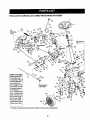
Parts List .................................................
25
.................................................
9
Espan61 ..................................................
42
...........................................
14
Customer Support ..................................
64
Safe Operation
Slope Gauge
Setting
................................
Practices ..........................
............................................
Up .................................................
Operation
Maintenance
Page
Content
2
Information
LIMITED WARRANTY ON LAWN UTILITY VEHICLE: For two (2) years from the date of purchase, if this Craftsman Riding
Equipment is maintained, lubricated and tuned up according to the instructions in the owner's manual, Sears will repair or
replace free of charge any parts that are found to be defective in material or workmanship according to the guidelines of
coverage listed below.
Sears will also provide free labor for these applicable warranted parts for the two full years. During first 30 days of purchase,
there will be no charges to service the product at your home for issues covered by this warranty. (See exclusions below),
For your convenience, IN HOME warranty service will still be available after the first 30 days of purchase, but a trip charge will
apply. This charge will be waived if the product is dropped off at an authorized Sears location, For the nearest authorized Sears
location, please call 1-800-4-MY-HOM E®. This warranty applies only while this preduct is within the United States.
EXCLUSIONS
This Warranty does not cover:
•
Expendable items which become worn dudng normal use, including but not limited to blades, spark plugs, air cleaners,
belts, and oil filters.
•
Standard Maintenance Servicing, oil changes or tuoe-ups
•
Tire replacement or repair caused by punctures from outside objects, such as nails, thorns, stumps, or glass.
•
Repairs necessary because of operator abuse, including but not limited to, damage caused by towing objects beyond the
capability of the riding equipment, impacting objects that bend the frame or crankshaft, or over-speeding the engine.
Repairs necessary because of operator negligence, including but not limited to, electrical and mechanical damage caused
by improper storage, failure to use the proper grade and amount of engine oil, failure to keep the deck clear of flammable
debris, or failure to maintain the equipment according to the ibstructions contained in the owner's manual.
•
Engine (fuel system) cleaning or repairs caused by fuel determined to be contaminated or oxidized (stale). In general, fuel
should be used within 30 days of its pumhase date.
•
Normal deterioration and wear of the exterior finishes, or product label replacement.
•
Riding equipment used for commercial or rental purposes.
LIMITED WARRANTY ON BATTERY
For ninety (90) days from date of purchase, if any battery Included with this riding equipment proves defective in matedal or
workmanship and our testing determines the battery will not hold charge, Sears will replace the battery at no charge. During the
first 30 days of purchase, there will be no charges to replace the battery at your home, After the first 30 days, for your
convenience, IN-HOME warranty service will still be available but a trip charge will apply. This charge will be waived if the
Craftsman product is dropped of at an authorized Sears location. For the nearest authodzed Sears location, please call 1-800-4MY-HOME®. This battery warranty applies only while this product is within the United States. This warranty gives you specific
legal rights, and you may also have other rights, which vary, from state to state.
Sears, Roebuck
Horsepower: ...............................
Engine Oil ...................................
Fuel ............................................
Spark Plug: .................................
Engine: ........................................
Ignition Key .................................
and Co.,Dept.817WA,
6.75
22 oz. or 0.65 liter
Unleaded Regular
PIN 692051
12607-0324-E1
PIN 725-0201
Hoffman Estates,
IL 60179
Model Number ........................... 247.270250
Sedal Number ...........................................................
Date of Purchase ......................................................
Record both serial number and date of purchase and keep
in a safe place for future reference.
WARNING:
This symbol points out important safety instructionswhich, if not followed, could endanger
the personal safety and/or property of yourself and others. Read and follow all instructions in this manual
before attempting to operate this machine. Failure to comply with these instructions may result in personal
injury. When you see this symbol--heed itswarning.
WARNING: The Battery and Engine Exhaust contains chemicals known to the State of California
to cause cancer, birth defects or other reproductive harm. The battery and posts contain lead;
wash hands after handling.
WARNING: This machine was built to be operated according to the rules for safe operation in this
manual. As with any type of power equipment, carelessness or error on the part of the operator can result in
sedous injury. This machine is capable of amputating hands and feet and throwing objects. Failure to
observe the following safety instructions could result in serious injury or death.
12. A missing or damaged discharge cover can cause blade
contact or thrown object injuries.
13. Stop the blade(s) when crossing gravel drives, walks, or
roads and while not cutting grass.
14. Watch for traffic when operating near or crossing
roadways. This machine is not Intended for use on any
public roadway.
15. Do not operate the machine while under the influence of
alcohol or drugs.
16. Mow only in daylight or good artificial light. Never carry
passengers.
17. Disengage blade(s) before shifting into reverse. Back up
slowly. Always look down and behind before and while
backing to avoid a back-over accident.
18. Slow down before tuming. Operate the machine
smoothly. Avoid erratic operation and excessive speed.
19. Disengage blade(s), sat parking brake, stop engine and
wait until the blade(s) come to a complete stop before
removing grass catcher, emptying grass, unclogging
chute, removing any grass or debds, or making any
adjustments.
20. Never leave a running machine unattended. Always turn
off blade(s), place transmission in neutral, set parking
brake, stop engine and remove key before dismounting.
21. Use extra care when loading or unloading the machine
into a trailer or truck. This unit should not be ddven up or
down ramp(s), because the unit could tip over, causing
serious personal injury. The unit must be pushed
manually on ramp(s) to load or unload pmpedy.
22. Muffierandenginebecomehotandcancauseabum.Do
not touch.
23. Check overheed clearances carefully before ddving
under low tree branches, wires, door openings etc.,
where the operator may be struck or pulled from the unit,
which could result in serious injury.
24. Disengage all sttachment clutches, depress the brake
pedal completely and shift into neutral before attempting
to start engine.
25. Your machine is designed to cut normal residential grass
of a height no more than 10". Do not attempt to mow
through unusually tall, dry grass (e.g., pasture) or piles of
dry leaves. Dry grass or leaves may contact the engine
exhaust and/or build up on the mower deck presenting a
potential fire hazard.
General Operation
1.
Read, understand, and follow all instructions on the
machine and in the manual(s) before attempting to
assemble and operate. Keep this manual in a safe place
for future and regular reference and for ordering
replacement parts.
2. Be familiar with all controls and their proper operation.
Know how to stop machine and disengage them quickly.
3. Never allow children under 14 years old to operate this
machine. Children 14 years old and over should read and
understand operation instructions and safety rules in this
manual and should be trained and supervised by parent.
4.
Never allow adults to operate this machine without
proper instruction.
5. To help avoid blade contact or a thrown object injury,
keep bystanders, helpers, children and pets at least 75
feet from the machine while it is in operation. Stop
machine if anyone enters the area.
6. Thoroughly inspect the area where the equipment is to
be used. Remove all stones, sticks, wire, bones, toys,
and other foreign objects which could be picked up and
thrown by the blade(s). Thrown objects can cause
serious personal injury.
7. Plan your mowing pattern to avoid discharge of material
toward roads, sidewalks, bystanders and the like. Also,
avoid discharging matedal against a wall or obstruction
which may cause discharged material to dcochet back
toward the operator.
8. Always wear safety glasses or safety goggles during
operation and while performing an adjustment or repair to
protect your eyes. Thrown objects which dcoshet can
cause serious injury to the eyes.
9. Wear sturdy, rough-soled work shoes and close-fitting
slacks and shirts. Loose fitting clothes and jewelry can be
caught in movable parts. Never operate this machine in
bare feet or sandals.
10. Be aware of the mower and attachment discharge
direction and do not point it at anyone. Do net operate the
mower without the discharge cover or entire grass
catcher in its proper place.
11. Do not put hands or feet near rotating parts or under the
cuffing deck. Contact with the blade(s) can amputate
hands and feet.
3
degrees.When goingdownhill,the extraweighttendsto
pushthe tractorand may causeyouto loosecontrol. (e.g.
tractor may speed up,brakingand steedngabilityare
reduced,attachmentmay jsck-kniteand causetractorto
overfum).
26. Use only accesaories and attachments approved for this
machine by the machine manufacturer. Read,
understand and follow all instructions provided with the
accessory or attachment.
27. Data indicates that operators, age 60 years and above,
are involved in a large percentage of tractor-relsted
injuries. These operators should evaluate their ability to
operate the tractor safely enough to protect themselves
and others from serious injury.
28. If situations occur which are not covered in this manual,
use care and good judgment. Contact Sears service
center for assistance.
Children
1,
Slope Operation
Slopes are a major factor related to loss of control and tipover accidents which can result in severe injury or death. All
slopes require extra caution. If you cannot back up the slope
or if you feel uneasy, do not mow it.
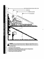
For safety, use the slope gauge included as part of this
manual to measure slopes before operating this unit on s
sloped or hilly area. If the slope is greater than 15 degrees as
shown on the slope gauge, do not operate this unit there.
Do:
1.
2.
3.
4.
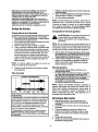
Mow up and down slopes, not across. Exercise extreme
caution when changing direction on slopes.
Watch for holes, ruts, bumps, rocks, or other hidden
objects. Uneven terrain could overturn the machine. Tall
grass can hide obstacles.
Use slow speed. Choose a low enough speed setting so
that you will not have to stop or shift while on the slope,
Tires may lose traction on slopes even though the brakes
are functioning properly. Always keep machine in gear
when going down slopes to take advantage of engine
braking action.
Follow the manufacturer's recommendations for wheel
2.
weights or counterweights to improve stability of the
machine. Usa extra care with grass catchers or other
attachments. These can change stability of the machine.
5. Keep all movement on the slopes slow and gradual. Do
not make sudden changes in speed or direction. Rapid
engagement or braking could cause the front of the
machine to lift and rapidly flip over backwards which
could cause serious injury.
6. Avoid starting or stopping on a slope. If tires lose traction,
disengage the blade(s) and proceed slowly straight down
the slope.
Do Not"
1.
2.
3.
4.
5.
6.
7.
Tragic accidents can occur it the operator is not alert to
the presence of children. Children are often attracted to
the machine and the mowing activity. They do not
understand the dangers. Never assume that children will
remain where you last saw them.
a. Keep children out of the mowing area and in
watchful care of a responsible adult other than the
operator.
b. Be alert and turn machine off if a child enters the
area.
c. Before and while backing, look behind and down
for small children.
d. Never carry children, even with the blade(s) shut
off. They may fall off and be seriously injured or
interfere with safe machine operation.
e. Usa extreme care when approaching blind
corners, doorways, shrubs, trees or other objects
that may block your vision of a child who may run
into the machine.
f.
Disengage the cutting blede(s) before shifting in
reverse. The =No-Cut-in Reverse" feature
emphasizes not to cut in reverse and to avoid
back-over accidents; do not defeat it.
g.
Keep children away from hot or running engines.
They can suffer burns from a hot muffler.
h. Remove key when machine is unattended to
prevent unauthorized operation.
Never allow children under 14 years old to operate the
machine. Children 14 years old and over should read and
understand the operation instructions and safety rules in
this manual and should be trained and supervised by a
parent.
Service
Safe Handling Of Gasoline
1.
Do not turn on slopes unless necessary;, then, turn slowly
and gradually downhill, if possible.
Do not mow near drop-off sites, ditches or embankments.
The mower could suddenly turn over if a wheel is over the
edge of a cliff, ditch, or if an edge caves in.
Do not try to stabilize the machine by putting your foot on
the ground.
Do not use a grass catcher on steep slopes.
Do not mow on wet grass. Reduced traction could cause
sliding.
Do not shift to neutral and coast downhill. Over-speeding
may cause the operator to lose control of the machine
resulting in serious injury or death.
Do not tow heavy pull behind attachments (e.g. loaded
dump cart, lawn roller, etc.) on slopes greater than 5
To avoid personal injury or property damage usa extreme
care in handling gasoline. Gasoline is extremely
flammable and the vapors are explosive. Serious
personal injury can occur when gasoline is spilled on
yourself or your clothes which can ignite. Wash your skin
and change clothes immediately.
a. Usa only an approved gasoline container.
b. Never fill containers inside a vehicle or on a truck
c.
d.
4
or trailer bed with a plastic liner. Always place
containers on the ground away from your vehicle
before filling.
When practical, remove gas-powered equipment
from the truck or trailor and refuel it on the ground.
If this is not possible, then refuel such equipment
on a trailer with a portable container, rather than
trom a gasoline dispenser nozzle.
Keep the nozzle in contact with the rim of the fuel
tank or container opening at all times until fueling
is complete. Do not use a nozzle lock-open
device.
e. Extinguish
all cigarettes,
cigars, pipes and other
sources of ignition.
f.
Never fuel machine indoors.
g. Never remove gas cap or add fuel while the
engine is hot or running. Allow engine to cool at
least two minutes before refueling.
h. Never over fill fuel tank. Fill tank to no more than
½ inch below bottom of filler neck to allow space
for fuel expansion.
i.
Replace gasoline cap and tighten securely.
j.
If gasoline is spilled, wipe it off the engine and
equipment. Move unit to another area. Wait 5
minutes before starting the engine.
k. To reduce fire hazards, keep machine free of
grass, leaves, or other debris build-up. Clean up
oil or fuel spillage and remove any fuel soaked
debris.
L
Never store the machine or fuel container inside
where there is an open flame, spark or pilot light
as on a water heater, space heater, fumace,
clothes dryer or other gas appliances.
m. Allow a machine to cool at least 5 minutes before
storing.
General Service
1.
2.
3.
4.
5.
6.
7.
8.
9.
10.
11.
Never run an engine indoors or in a poorly ventilated
area. Engine exhaust contains carbon monoxide, an
odorless, and deadly gas.
Before cleaning, repeidng, or inspecting, make certain
the blade(s) and all moving parts have stopped.
Disconnect the spark plug wire and ground against the
engine to prevent unintended starting.
Periodically check to make sure the blades come to
complete stop within approximately (5) five seconds after
operating the blade disengagement control. If the blades
do not stop within the this time frame, your unit should be
serviced professionally by an authorized dealer.
Check brake operation frequently as it is subjected to
wear dudng normal operation. Adjust and service as
required.
Check the blade(s) and engine mounting bolts at
frequent intervals for proper tightness. Also, visually
inspect blade(s) for damage (e.g., excessive wear, bent,
cracked).
12.
13.
14.
Replace the blade(s) with the original equipment
manufacturer's (O.E.M.) blade(s) only, listed in this
manual. "Use of parts which do not meet the original
equipment specifications may lead to improper
performance and compromise safety!"
Mower blades are sharp. Wrap the blade or wear gloves,
and use extra caution when servicing them.
Keep all nuts, bolts, and screws tight to be sure the
equipment is in safe working condition.
Never tamper with the safety interlock system or other
safety devices. Check their proper operation regutarly.
After striking a foreign object, stop the engine, disconnect
the spark plug wire(s) and ground against the engine.
Thoroughly inspect the machine for any damage. Repair
the damage before starting and operating.
Never attempt to make adjustments or repairs to the
machine while the engine is running.
Grass catcher components and the discharge cover are
subject to wear and damage which could expose moving
parts or allow objects to be thrown. For safety protection,
frequently check components and replace immediately
with original equipment manufacturer's (O.E.M.) parts
only, listed in this manual. "Use of parts which do not
meet the original equipment specifications may lead to
improper performance and compromise safety!"
Do not change the engine governor settings or overspeed the engine. The governor controls the maximum
safe operating speed of the engine.
Maintain or replace safety and instruction labels, es
necessary.
Observe proper disposal laws and regulations for gas,
oil, etc. to protect the environment,
Your Responsibility
Restrict the use of this power machine to persons who
read, understand and follow the warnings and instructions
in this manual and on the machine.
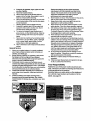
Illustrated below are safety labels on the equipment.
For a full list of part numbers and location of all the
labels, see page 36.
I_FARTINQ
114s'lrN U C'lr lid HS
m
e|41_t_
one,
• _,r_N
DANGER
5
ttu4
a
_,w
_n
I_l_ iod
h m
(D
la=
0
0
"o
feet). A lawn utility
WARNING:
Do not
vehicle
mowcould
on inclines
overturn
with
and
a slope
causeinserious
excessinjury.
of 15 degrees
Operate (a
these
rise vehicles
of approximately
up and down
2.5 feet
slopes,
every
never
10
across the face of slopes.
.q
0
D.
1.
2.
3,
4,
Fold this page along dotted line indicated above.
Hold page before you so that its left edge is vertically parallel to a tree trunk or other updght structure.
Sight across the fold in the direction of hill slope you want to measure.
Compare the angle of the fold with the slope of the hill.
1.
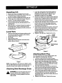
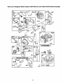
Unpacking Unit
1.
2.
3.
4.
5.
6.
Remove all screws and staples from the crete.
Holding sides of the crete firmly, lift top of the crate
up and set itaside. Avoid tire punctures.
Remove and discard plastic bag covering the unit.
Lift the rear of the vehicle off the crate. Repeat for
the front. This may require two people.
Remove plastic bag and its contents (owner's
manual, ignition keys etc.) that are packed on the
steering shaft.
Refer to Figure 7 in Owner's Manual for location of
the parking brake. Check to make sure that the
parking brake is disengaged so that the vehicle can
be rolled forward.
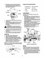
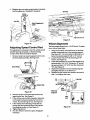
2.
3.
4.
step 2, through the left hole on the chute and the
corresponding hole on the deck. See Figure 2.
Thread the screw a few turns to secure, but do not
Loose Parts
1.
•
•
•
Remove loose parts from the grass catcher and/or
the crate very carefully. Compare with list below
and part illustrations in Figure 1.
Mulch plug
Side-discharge chute
Plastic bag carrying operator's manual and two
ignition keys(not shown)
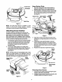
Lower the cutting deck to the lowest position by
sliding the deck lift lever to the appropriate slot
indicated bythe label. Refer to Figure 7 and
description on page 9 for more details.
Remove the thumb screw and flat washer attaching
the two ends of the grass catcher chute to the deck.
Slide the grass catcher chute out of the vehicle
housing; remove and save the hardware.
Place the side-discharge chute on the deck so that
the two holes on itstwo ends align with the two
holes on the deck where the grass catcher chute
was attached. See Figure 2.
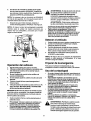
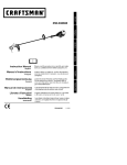
Insert a thumb screw and a flat washer, removed in
5.
tighten at this time.
Repeat on the dght side. Tighten both screws.
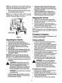
Thumb
-Rat Washer
Side-Discharge Chute
Figure 2
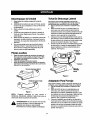
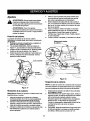
Attaching Mulch Plug
To mulch grass and recirculate clippings back to the
lawn, attach the mulching plug to the deck.
1.
2.
Figure 1
NOTE: Any reference in this manual to RIGHT, LEFT,
TOP and BOTTOM of the tractor is observed from the
operator's position when sitting on the vehicle seat.
Attaching Side-Discharge
Chute
WARNING:
Do not mow grass if any one of
the grass catcher chute, discharge chute or
mulch plug is not firmly installed on the lawn
utilityvehicle.
3.
4.
5.
Lower the cutting deck to the lowest position.
Remove the thumb screw and flat washer attaching
the two ends of the discharge chute to the deck.
(Refer to Figure 2 for the discharge chute set-up.)
Slide the discharge chute out of the deck housing;
remove and save the hardware.
Place the mulch plug on the deck so that the two
holes on its two ends align with the two holes on the
deck where the discharge chute was attached.
Insert thumb screw and fiat washer, removed in
step 2, through the left hole on the mulch plug and
corresponding hole on the deck. See Figure 3.
Thread the screw a few turns to secure, but do not
tighten at this time.
Repeat on the right side. Tighten both screws.
Grass Catcher
1,
Flat Washer
2.
Deck
_
Chute
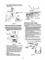
Place the cuffing deck in the lowest posiUon by
sliding the deck lift lever to the appropriate slot.
Slide the elbow of the grass catcher chute through
the vehicle frame and align the chute opening with
the corresponding opening on the vehicle frame.
See Figure 5.
Vehicle Frame
Grass Catcher
Chute
Deck
-Lift
Lever
Mulch Plug
Figure 3
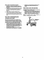
NOTE: The grass bag must be in position, on the
vehicle, for any kind of mowing operation, including
mulching and side-discharge of grass clippings.
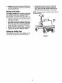
Attaching Grass Catcher
The grass catcher is assembled at the factory and
attached to the vehicle for shipping convenience. The
grass catcher has to be attached to the vehicle only
when cuffing grass and/or bagging the grass clippings.
If the grass catcher was removed from the unitfor some
reason, re-attach by following instructions below.
1.
Hold the grass catcher by the two handles and slide
it on top of the utility bed at the back of the vehicle.
Make sure that the side of the grass catcher with
the opening is aligned with the vehicle frame
behind the seat.
2.
Pull the two retainer straps on two sides of the
grass catcher and attach loose ends of the strap to
the respective hook on the frame of the vehicle.
See Figure 4.
Figure 5
3.
4.
5.
Align the two holes on the other end of the chute
with the two corresponding holes on the deck. See
Figure 6.
Insert thumb screw and fiat washer, removed
earlier, through the left hole on the grass catcher
chute and corresponding hole on the deck. Thread
the screw a few turns to secure, but do not tighten.
See Figure 6.
Repeat on the right side. Tighten both screws.
Thumb
Screw
NOTE: The bag switch will automatically shut off the
engine if the grass catcher is not attached to the unit
while cutting grass. Do not remove the bag even when
using the mulch plug or the side-discharge chute.
Grass
Grass Catcher
Handle
Catcher
Deck
Alignholeshere
Grass Catcher
Chute
Figure 6
Removing
strap
1.
2.
Figure 4
Grass
Catcher
Unhook the two retainer straps securing the grass
catcher to the frame of the vehicle.
Holding the grass catcher firmly by the handle, slide
it slightly upward and outward to remove.
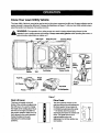
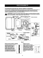
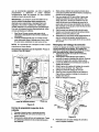
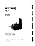
Know Your Lawn Utility Vehicle
The Lawn Utility Vehicle is meant to be used as both a riding lawn mower and a utility cart. Its grass collector can be
easily removed to expose the utility bed. Compare the illustrations in Figure 7 with your lawn utilityvehicle to learn
about the location and features of its vadous controls.
,_
WARNING:
operator's eyes,
The
causing
operation
severe
of any
eye riding
damage.
mower
Always
can result
wear in
safety
foreign
glasses
objectswhile
being
operating
thrown into
the the
mower, or
3erforming any adjustments or repairs on it.
Ignition
Switch
Rnger
Parldng
Brake
_Gual't:l
:uel Tank
Muffler
RII/Dlpstick
Figure 7
Deck Lift Lever
Drive Pedal
This lever is located on the left
fender of the vehicle and adjacent to
the shift lever. It is used to change
the height of the cutting deck. Move
the lever to the right and slide it to
the position desired. Make sure it is
firmly placed in the notch intended.
Follow the label on the unit
indicating the cuffing height
positions.
The drive pedal is located on the
right front side of the unit adjacent to
the brake pedal. Ground speed is
controlled by depressing this pedal
-- the further down the pedal is
depressed, the faster the vehicle will
move. The pedal returns to its
original position when not
depressed. For further details, see
next section.
SLOW
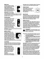
ShiR Lever
(off) position when (1) starting the engine, (2) travelling
in reverse, and (3) if the operator leaves the seat.
This lever is located on the left
side of the fender and has three
Choke
clearly marked positions:
FORWARD (F), REVERSE (R)
and NEUTRAL (N). Follow the
label on the unit to place the shift
lever in the position desired.
This is located in front of the seat
frame. Pull the choke control
outward to activate choke for
starting engine; push it inward once
the engine starts.
IMPORTANT:The brake pedal
must be depressed completely
and the vehicle not in motion while sliding the shift lever
to another position. Never force the shift lever to avoid
damage to the transmission.
Parking
Control
Brake Pedal
This pedal is located on the right front side of the unit
and to the left of the drive pedal. It is used for sudden
stops and/or for setting the parking brake. The brake
pedal must be fully depressed to activate the safety
interlock switch when starting the vehicle.
Brake
The parking brake has to be set
(1) to park the vehicle, or (2) to
leave the engine running when
the operator leaves the seat.
Depress the brake pedal
completely and push the parking
brake lock to activate it. Once the
parking brake is locked, you can
take your foot off the brake pedal.
To release the parking brake,
depress the brake pedal lightly.
Safety Interlock
This unit is equipped with a safety intedock system for
your protection. The safety switches are connected to
the brake pedal, the steering column, the shift lever,
and the seat and will shut off the engine automatically
under certain conditions. These conditions are
descdbed below. Read this section and be aware of the
purpose of this safety mechanism at all times; do not
tamper with its working.
IMPORTANT:Always set the parking brake when leaving
the vehicle unattended.
_lb
Ignition Switch
system is malfunctioning.
This switch is located on the
steering column and is used to
start the engine. Insert key into
slot and turn clockwise to START
position indicated by the label on
the switch. Once the engine has
started, release the key and itwill
return to RUN position. To shut
engine off, move shift lever to (N),
set the parking brake and turn key to the OFF position.
Cup
WARNING:
operate the riding
To mower
avoid serious
if the safety
injury,intedock
do not
The purpose of the safety intedock system is four-fold:
a.
b.
c.
d.
Holder
This vehicle offers the convenience of carrying your
beverage while working. The cup holder is located on
the fender to the right of the seat above the battery,
to prevent the engine from starting unless the
brake pedal is depressed;
to shut off the engine if the blade control lever is
not disengaged when the shift lever is put into
reverse;
to shut the engine off when the operator leaves
the seat without engaging the parking brake;
to shut the engine off if an attempt is made to
cut grass without the grass catcher propedy
attached to the unit.
Seat Switch: This switch is located under the seat and
is a safety mechanism. When the parking brake is
disengaged and blade control lever engaged, the
operator must remain seated at all times for the engine
to run. If he/she leaves the seat without disengaging
blade control lever and turning engine off, this switch
will automatically shut the engine oft regardless of
whether the parking brake is engaged.
Blade Control Lever
This lever is located on the left
side of the vehicle next to the
steedng wheel. Move the blade
control lever to ON position to
engage power to the cuffing
deck, and move it to OFF to
disengage.
Reverse Switch: This switch is located near the shift
lever and will automatically shut off the engine if the
blade control lever is moved to (ON) position when the
shift lever is in (R). That is, the vehicle will not move in
reverse direction with the blade control lever engaged.
IMPORTANT..The blade control
lever must be in the disengaged
10
Brake Switch: This switch is located under the brake
1.
2.
pedal assembly. The engine will not start without first
depressing the brake pedal. This switch will also shut
off the engine if the operator attempts to get off the unit
without setting the parking brake,
3.
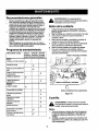
Refer to the chart above for proper grade of oil.
Use a high quality detergent oil classified =For
service SF, SG,SH, SJ" or higher.
Do not use special additives.
NOTE: Synthetic oil meeting ILSAC GF-2, API
certification and API service symbol with "SJ/CF
Energy Conserving" or higher is an acceptable oil at all
temperatures. Use of synthetic off does not alter
required oil change intervals.
Blade Control Switch: This switch is located in the
steering column. If the operator attempts to start the
engine, get off the seat or remove grass bag with the
blade control lever stillengaged, it will shut engine off.
Grass Bag Switch: This switch is located in the
bulkhead behind the engine. If the operator attempts to
cut grass when the grass catcher is not properly
attached to the vehicle, itwill shut engine off.
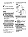
Filling Up Gasoline
WARNING:
Before Starting
NOTE:
and/or
fill-up,
before
Filling Up Oil
Check oil level in the engine oilsump before starting the
engine. (Oil sump capacity: 22 ozJ0.65 liter)
1.
2.
3.
4.
Place the vehicle on level ground and flip the seat
up to access the engine.
With a dry rag, clean the area around the oil fill on
the engine.
Remove dipstick and wipe it clean with cloth.
Replace and tighten the dipstick. Remove the
dipstick again and check the oil level mark on it.
The oil level should be at FULL line on the dipstick.
If the level is short of that, add oil to the oil fill slowly.
Recheck the oil level on the dipstick. If needed, add
more oil. Do not overfill.
1.
2.
On a vehicle which has already been started
operated once immediately prior to this gasoline
turn engine off and let cool at least two minutes
removing gas cap.
Remove gas tank cap and fill tank to approximately
1.5 inches below top of neck to allow for fuel
expansion. Be careful not to overfill.
Replace cap on the gas tank and tighten to secure.
If fuel spills on part of engine or vehicle, wait until it
evaporates before starting engine.
Type of Gasoline
•
•
NOTE: The lawn utility vehicle is shipped with oil in the
engine crankcase.
5.
Fill fuel tank outdoors or in well-
ventilated area, away from sparks, open
flames, pilot lights, heat and other ignition
sources.
Place the dipstick in position and tighten to secure.
Type of Oil
•
Use clean, fresh, regular unleaded gasoline with
minimum 85 octane rating.
Do not use gasoline mixed with methanol, or
gasoline which has been stored for more than 30
days. Always purchase fuel in quantity that can be
used up within 30 days. Fresh fuel prevents gum
from forming in the fuel system or on carburetor.
Do not mix gasoline with engine oil.
NOTE: Some fuels, called oxygenated or reformulated
gasoline, are blended with alcohols or ethers. Using
these blends frequently can damage the fuel system or
affect performance. If engine performance is affected,
use gasoline with lower percentage of alcohol or ether.
SAE Viscosity Grades
lIll
_mi[llvdE_
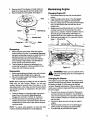
Starting the Engine
°F -20 °
O°
20 °
3240 °
60 _
80 °
1.
100 °
3tading temperature range anticipated before next oil change
2.
3.
*CAUTION: Air cooledenginesrunhotterthanautomotive
_=ngines.
The useof non-syntheticmulti-viscosity
oils(5W30, 10W-30 etc.) in temperaturesabove 40°F willresultin
nigherthannormaloilconsumption.When usinga multi/iscosltyoil, checkoil levelmore frequently.
'* CAUTION: SAE 30 oil, if usedbelow40°F, will resultin
lard startingand poesibleengineboredamagedue to
nadequatelubrication.
4.
5.
6.
11
Looking under the seat and towards the front of the
engine, check that spark plug wire is connected.
Occupy the seat and insert key into ignition switch.
Place blade control lever in OFF position. (Refer to
Figure 7 for location of controls mentioned here.)
Engage parking brake.
Pull choke control outward into the Choke position.
Tum ignition key clockwise to START position.
After the engine starts, release the key. It will retum
to RUN position automatically.
NOTE: Do not hold the key in the START position for
longer than ten seconds at a time. Doing so may cause
damage to your vehicle engine's electric starter.
7.
•
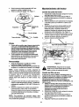
After the engine starts, press choke control inward,
thus closing the choke. See Figure 8.
NOTE:
Do not leave
the choke control
•
on while
operating the unit. Doing so will result in a "rich" fuel
mixture and cause the engine to run poorly.
To move in reverse: Place blade control lever in
OFF position. Place shift lever in the (R) position,
check that the area behind is clear and then slowly
depress the drive pedal.
To drive on slopes: Refer to Slope Gauge on
page 6 to determine slopes or inclines where you
can operate your unit safely. Do not operate the
vehicle if the gauge indicates a steep incline.
Stopping the Vehicle
1.
2.
Release drive pedal and depress broke pedal.
When the mower comes to a complete stop, place
the shift lever in neutral.
3.
Continue to depress the brake pedal while you
push the parking brake. Take your foot off the brake
pedal when the parking brake is locked.
Tum ignition keyto OFF position and remove key.
4.
NOTE: Do not leave key in the ON position when you
are not operating the mower. Such action will drain the
battery dead.
Emergency Stopping
To stop the vehicle immediately in an emergency, raise
your body up and off the seat.
Figure 8
Operating the Vehicle
Using as Mower
1.
2.
•
3.
4.
5.
6.
Follow instructions to start the engine.
Put the deck at the highest cutting position by
sliding the deck lift lever to the appropdate position.
Move the blade control lever to ON position.
If mowing grass, adjust the deck to the cutting
height desired.
Depress brake pedal to disengage parking brake.
Place shift lever in either (F')or (R) position as you
desire. Look to the rear and check before
reversing the vehicle.
•
•
•
IMPORTANT: Do not move the shift lever when the
vehicle is in motion. Always use brake pedal to bdng
the vehicle to a complete stop before moving shift lever.
7.
Release the brake pedal and gradually depress the
ddve pedal.
Do not mow at high ground speed, especially if a
mulch kit or grass collector is installed.
For best results, it is recommended that the first two
laps be cut with the discharge thrown towards the
center. Then reverse the direction to throw rest of
the discharge to the outside. This will give a better
appearance to the lawn.
Do not cut grass too short. Short grass invites weed
growth and yellows quickly in dry weather.
Do not attempt to mow heavy brush and weeds and
extremely tall grass. Your mower is designed to
mow lawns, not clear brush.
Keep the blades sharp and replace blades when
worn. Refer to page 14 for blade care instruction.
WARNING:
Plan your mowing pattem to
avoid discharge of materials toward reads,
sidewalks, by-standers and the like. Also, avoid
discharging material against a wall or
obstruction which may cause discharged
material to ricochet back toward the operator.
WARNING:
leave the
the blade
seat of
the
vehicle without Do
firstnot
placing
control
lever in the disengaged (OFF) position,
depressing the brake pedal and engaging the
parking brake. If leaving the unit unattended,
also turn the ignition key off and remove key.
To Empty Grass Catcher
WARNING:
1.
Avoid sudden starts, high speed
and sudden stops.
2.
To move forward: Place the shift lever in the (F)
position, then slowly depress the ddve pedal until
the desired speed is achieved.
3.
12
Stop the mower completely, set parking brake and
take ignition key out. Get off the seat.
Unhook bag straps from the mower frame. Pull up
the grass catcher bag by the two handles and carry
it to the proper disposal site.
Hold bag away from your body while emptying it.
4.
Remove grass catcher to expose the utility bed.
See Figure 9, Follow instructions on page 7 for
grass catcher removal. Exemise caution in ddving
the vehicle when hauling things on its utility bed.
Replace the bag on to the mower. Hook the loose
end of the bag retainer straps to the vehicle frame
to secure the grass bag.
Using as Mulcher
NOTE: Total load capacity, including operator, should
not exceed 400 Ibs.
This vehicle is shipped with a mulch plug to recirculate
grass clippings into the lawn. The ultra-fine clippings
are forced back into the lawn where they act as a
natural fertilizer. Observe the following for best results:
•
•
•
•
Attach the mulch plug to the cutting deck following
instructions on page 7.
Never attempt to mulch if the lawn is damp. Wet
grass tends to stick to the undemide of the cutting
deck preventing proper mulching of the clippings.
Do not attempt to mulch more than 1/3 the total
height of the grass or approximately 1-1/2 inches,
Maintain a slow ground speed to allow the grass
clippings more time to be effectively mulched.
Using as Utility Cart
The lawn utility vehicle, as its name suggests, can be
used as both a riding lawn mower and a utility cart.
Figure 9
13
General Recommendation
•
•
•
•
Always observe safety rules when performing any
maintenance.
The warranty on this lawn utility vehicle does not
cover items that have been subjected to operator
abuse or negligence. To receive full value from the
warranty, operator must maintain the equipment as
instructed in this manual.
We do not recommend the use of pressure
washers or garden hose to clean your unit. These
may cause damage to electrical components,
spindles, pulleys, beadngs or the engine. The use
of water may shorten life of your lawn utility vehicle
and reduce its serviceability.
Follow the schedule below to ensure best
_lb
performance by your lawn utilityvehicle.
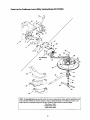
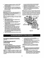
6.
7.
Removing Deck
1.
2.
3.
4.
5.
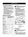
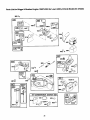
Maintenance Schedule
Task to be performed
Every 8
hours of
operation
Every 25
hours of
operation
job without firstNever
WARNING:
disconnecting
attemptanymaintenance
the spark plug
wire and grounding against the engine.
Place the blade control lever in the disengaged
(OFF) position and engage the parking brake.
Lower the cutting deck to the lowest position.
Disconnect spark plug wire and ground.
Remove all three hairpin clips and flat washers that
secure the cutting deck to the hanger links. See
Figure 10.
Slide the deck to the left to disengage it from the
hanger pins, and allow it to drop to the ground.
Remove belt from around spindle pulley.
To attach the deck to the mower, align the deck
with the hanger pins and insert the three hairpin
clips removed earlier.
At start of
season
Remove hairpin cl , & washer
Engine:
Check oil level
./
Change oil
Service air cleaner
e/
Service spark plug
Clean debris
Clean cooling fins
_f
Equipment:
Clean equipment
Check/sharpen blade
Removedeck fromthe hangers
,_
Figure 10
Lubricate pivot points
Lubricate front wheels
,_
Lubricate steering shaft
_t
Check brake
_f
Cutting Blade
_lb
ARNING:
your
hands
by wearing
heavy
gloves orProtect
by using
a rag
to grasp
the
cutting blade. Avoid personal injury.
Check condition of belts
Removal
Check tire pressure
1.
Check battery fluid level
,_
2.
14
Remove deck
the deck over
Piece a block
baffle and the
from beneath the vehicle. Gently flip
to access the blade and the spindle.
of wood between the deck housing
cutting blade to act as a stabilizer.
3.
4.
Maintaining
Remove the 5/8" hex flange nut which holds the
blade to the blade spindle and the spindle shaft.
Remove blade from the spindle. See Figure 11.
Changing
Engine
Engine Oil
1.
Disconnect spark plug wire and ground against
engine.
2. Place the blade control lever in the disengaged
(OFF) position and engage the parking brake.
3. Remove cutting deck by removing the three hairpin
clips and flat washers that hold the deck to the
hanger links.
4. Making sure that all three belts are out of the way,
carefully unscrew the oil drain plug and collect
spent oil in a container. Hold the container close to
the drain plug to avoid spillage. See Figure 12.
5. Reinstall drain plug and reattach the cutting deck.
6. Refill with fresh engine oil. For instruction, refer to
page 11, Filling Up Oil.
Ball _dng
Iq-
.,_
Spindle Shaft
Flange Nut -___
Blade
Figure 11
Sharpening
1.
2.
When sharpening the blade, follow the original
angle of gdnd as a guide. It is extremely important
that each cutting edge receives an equal amount of
gnnding to prevent an unbalanced blade. An
unbalanced blade will cause excessive vibration
when rotating at high speeds, may damage the
mower and/or cause personal injury.
Test the blade for balance by balancing it on a
round shaft screwddver. Remove metal from the
Figure 12
heavy side until it balances evenly.
Reassembly
1.
2.
Before reassembling the blade to the unit, lubdcate
the spindle shaft with light oil (or engine oil).
Be sure to propedy align "star" fitting on blade with
=star" on spindle shaft.
,_
Changing
1.
4.
Air Cleaner
The engine on your lawn utility vehicle has an oval air
cleaner cartridge and a pre-cleaner. See engine parts
list starting on page 37 of this manual for the part
numbers. Regular maintenance of the air cleaner will
improve your vehicle's engine performance and extend
life of the engine.
NOTE: When replacing the blade, be sure to install the
blade with the side marked =Bottom" (or with part
number) facing the ground when the mower is in the
operating position. Also make sure that the entire blade
and spindle assembly is reattached in the right order.
See Figure 11.
3.
belts while draining
WARNING:
Makespent
sure oil
notortoremoving
spill oil on
thethe
oil
container.
Place the flange nut, removed eadier, and secure
blade firmly to the spindle. Blade Mounting
Torque: 95-122 N-M or 70-90 ft,-Ib, maximum.
Flip the deck back to its operating position and
reattach to the mower. Secure the deck to the deck
2.
hanger links by three hairpin clips and flat washers
removed eadier.
3.
NOTE: To ensure safe operation, all nuts and bolts
must be checked periodically for correct tightness.
4.
15
Service the air cleaner at the start of the season,
and every 25 hours of operation. You will have to
clean it more frequently if it is operated in extremely
dusty conditions. Replace air cleaner parts ifthese
are very dirty.
Disconnect spark plug wire and ground against
engine.
Place the blade control lever in the disengaged
(OFF) position and engage the parking brake.
Pivot the seat up and access the engine.
5.
Engine Tune-Up Specifications
Completely loosen the two screws that hold the
cover of the air cleaner. Remove the entire air
cleaner assembly from the base. Liftthe cover off
the air cleaner. See Figure 13.
• Armature air gap
0.006 - 0.014 inches
• Spark plug gap
0.020 inches
•
Intake
0.004 - 0.006 inch
•
Exhaust
0.009 - 0.011 inch
Cover
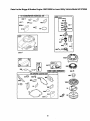
Lubrication
See Figure 15 for an illustration of the lube points
described below.
Base
•
•
Figure 13
6.
To clean cartridge, gently tap pleated paper side on
a flat surface.
7.
To clean pre-cleaner, separate it from the cartridge
and wash in liquid detergent and water. Air-dry
thoroughly. Re-assemble the dry pre-cleaner on
the cartridge.
•
•
•
,_
8.
9.
Blade Assembly: Lubricate blade assembly and
deck spindle before reassembling the blade either
after sharpening or replacement.
Pivot Points: Lubricate all pivot points on the drive
system, parking brake and lift linkage at least once
a season with light oil.
Steering Shaft: Lubricate steedng shaft and gear
spline at least once a season with light oil.
Gear: Lubricate teeth of the external steering gears
with automotive multi-purpose grease every 25
hours of operation or once a season.
Front Wheels: Lubricate the front wheels with
automotive grease once a season.
solvents to clean
WARNING:
Docartridge.
not use pressurized
Pressurizedair
airorcan
damage cartridge while solvents will dissolve it.
Install clean (or new) air cleaner assembly in base
so that the lip of the cartridge sits inside the base.
See Figure 13.
Place the cover over the air cleaner assembly and
secure with the two screws loosened in step 6.
Spark Plug
1. Clean area around the spark plug base.
2. Remove and inspect the spark plug.
3. Replace the spark plug if electrodes are pitted,
bumed, or the porcelain is cracked. See Figure 14.
4. Clean the spark plug and reset the gap to 0.020" at
least once a season or every 100 hours of
operation. See Figure 14. Replace if necessary.
Refer to parts list section for part number.
_ricete
Lubricate
NOTE: Do not sandblast spark plug. Spark plug should
be cleaned by scraping or wire brushing and washing
with a commercial solvent.
Lubricate
Figure 15: Lubrication Chart
Brake
.020" gap
During normal operation of any vehicle, the brake is
subject to wear and tear. Check the brake every 25
hours of operation by carrying out the following test:
1.
Figure 14
16
Release the parking brake and place the shift lever
in neutral. Depress the brake pedal and try to roll
the vehicle. It should not move. If the vehicle
moves, adjust the brake following instructions on
page 20.
2.
Set the parking brake and push the vehicle. Ifthe
rear wheels roll, adjust the brake following
instructions on page 20.
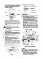
1.
2.
Remove throe screws holding the cup and battery
holder to the frame of the unit.
Remove red and black insulation caps from battery
terminals.
Tires
_lb
_r
airARNING:
pressure shown
Never
onexceed
sidewall
maximum
of the tire.
limit of
!' //
The recommended operating tire pressure is 20-22 psi
for both sets of tires. Refer to the tire sidewall for exact
tire manufacturer's recommendation. Do not
ovednflate. Uneven tire pressure could cause the
cutting deck to mow unevenly.
l
1\
Cable j
Battery
The battery is located under the cup holder to the right
of the seat. The positive battery terminal is marked Pos.
(+). The negative battery terminal is marked Neg. (-).
Figure 16
_
related
accessories
contain
and lead
ARNING:
Battery
posts,lead
terminals
and
compounds. Wash hands after handling.
3.
Remove battery terminal screws with a Phillips
screw driver or a 10 mm. socket wrench.
Attach the red battery cable to the positive terminal
(marked +), and the black battery cable to the
negative terminal (marked -) on the battery. See
Figure 16.
Align the cables with the slots in the battery cover
and tighten the screws on the battery terminals.
See Figure 16.
Always keep battery cables and terminals clean
and free of corrosive build-up.
After cleaning, apply a light coat of petroleum jelly
or grease to both terminals.
Always keep the rubber boot positioned over the
positive terminal to prevent shorting.
If removing the battery for any reason, disconnect
the NEGATIVE (black) wire from itsterminal first,
followed by the POSITIVE (red) wire. When reinstalling battery, always connect the POSITIVE
(red) wire to its terminal first, followed by the
NEGATIVE (black) wire.
4.
IMPORTANT:Be certain that wires are connected to the
6.
correct terminals; reversing them could change poladty
and cause damage to the engine's alternating system.
Cleaning the Equipment
•
1.
•
•
•
•
•
5.
WARNING:
Press the battery cables against
side of battery so that these do not make
contact with flange of rider frame when it is
opened or closed.
Check fluid level inside each cell of the battery
every two weeks and before and after charging.
Always maintain level just below the split rings.
Add only distilled water. Never add additional acid
or any other chemicals to the battery after initial
activation.
2.
3.
NOTE: ff you have operated the tractor for a long
period, check the fluid level of the battery as it can
overheat and lose fluid.
4.
Connecting
Battery
Cables
To reconnect battery cables, if the battery was removed
for some reason, follow instructions below.
17
Re-install the battery cover and cup holder.
Promptly wipe off any fuel or oil spilled on the
machine with clean cloth.
Clean the underside of the blade housing after
each mowing. Do not let clippings or debits
accumulate around the blade.
Using a brush or cloth, remove grass, chaff or
debds from the finger guard on the engine daily to
prevent overheating of the engine. Do not clean
with a fomeful spray of water since water
contaminates the fuel system.
Keep the governor linkage, springs and controls
free of debris.
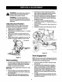
4.
Wearing a pair of heavy work gloves to prevent
injury, rotate the cutting blade so that it is pointed
side to side and perpendicular to the dder.
Measure the distance from each tip of the blade to
the ground, If the distance from both blade tips to
the ground is not the same, perform a side to side
levelling of the deck.
For levelling, remove the hairpin clip and flat
washer shown in Figure 18. Thread the ferrule in or
out as required.
Check for correct adjustment. Repeat adjustment if
necessary
Reattach the hairpin clip and flat washer to ferrule.
WARNING:
Never attempt any adjustment
while the engine is running, except where
specified in the operator's manual.
5.
WARNING:
For all other adjustments,
disconnect the spark plug wire(s) and ground
against the engine first. Then proceed with the
adjustment.
6.
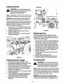
Adjusting Seat Position
7.
The seat position on the lawn utility vehicle can be
adjusted to maximize the operator's convenience.
8.
1.
2.
3.
4.
Stop the vehicle completely and engage the
parking brake. Tum ignition off.
Pivot the seat up, as shown in Figure 17, to access
seat hardware.
Deck Lift Lever-_._ _
Using a 9/16" wrench or socket, loosen the four
self-tapping screws on the bottom of the seat. See
Figure 17.
Slide the seat forward or backward in the slot, and
position it as desired. Retighten the four screws.
==
Ciip_
/[
,,
I
_
---
•
--_-
i
_
!1
-_-__I.....
i.,r
\W%,,,,,,,,,_
/// ,..................
_-,-__.
Figure 18
Deck Engagement
Figure 17
NOTE: The deck control cable is threaded at both ends;
adjustment has to be made at the end that attaches to
the control lever on the steering column.
Deck Levelling
1.
In case of uneven mowing, check air pressure in all
four tires and fill up if needed. Recommended air
pressure is 20-22 psi. If this does not correct the
problem, proceed with deck levelling.
1.
2.
IMPORTANT: Perform adjustments to the deck on a fiat,
level surface.
2.
3.
Place the vehicle on a level surface. Depress and
lock the parking brake. Disconnect the spark plug
wire and ground it.
Place the deck in the lowest cutting position by
sliding the deck lever to the appropriate position.
3.
18
Inspect the linkage and cable for damage through
wear and tear.
To determine whether adjustment is necessary,
perform the following test. The deck engagement
cable is correctly adjusted when the upper deck
drive belt has a maximum deflection of 0.5" in the
engaged position. When disengaged, the blade
brake should be firmly applied and the belt should
not drag.
To adjust, loosen the jam nuts and back the cable
out to tighten or thread inward to loosen. Use a 1/2"
wrench for this purpose.
4.
Retighten jam nuts when proper tension is reached.
Test the adjustment. Readjust if necessary.
Jam Nut
Jam Nut
Deck Engagement
Cable
............
Control
Rod
Adjust this ferrule
/
Figure 21
/
/
Wheel Alignment
Figure 19
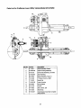
The front wheels should toe-in 1/16-5/16 inch. To adjust
toe-in, follow these steps:
Adjusting Speed Control Rod
This adjustment is necessary when the vehicle cannot
hold the full range of speeds, or shows belt drag
(=creep")when the drive pedal is released.
1.
1.
Remove hairpin clip secudng speed control rod to
the drive pedal assembly. See Figure 20.
2.
3.
Drive Pedal
\
4.
5.
Using 9/16" wrench, remove the hex nut and lock
washer holding ball joint to the steedng segment.
See Figure 22. You may need to hold the jam nut
below the steering segment with a 1/2" wrench.
Loosen the jam nut on the tie red using a 9/16"
wrench. See Figure 22.
Adjust the ball joint in or out until the wheels toe-in
approximately 1/16"-5/16" (Dimension =B" should
be approximately 1/16"-5/16" less than dimension
=A"). See Figure 22.
Replace the ball joint on to the steering segment,
and tighten the jam nut on the tie rod.
Replace the hex nut and lock washer, removed in
step 1, and tighten the screw.
Hex Nut
- Hairpin Clip
Waeher
Figure 20
2.
3.
4.
5.
6.
Rod
Segment
Remove the jam nut that secures ferrule to the
speed control rod. See Figure 21.
If the vehicle cannot attain all speeds, thread the
rod through the ferrule towards the front of the
mower, thus shortening the rod. See Figure 21.
If the vehicle shows belt drag, thread the rod
through the ferrule towards back of the vehicle,
thus lengthening the rod. See Figure 21.
Tighten the jam nut.
Run the vehicle to check for speed. Readjust if
necessary.
Ball
Joint
1/16-5/16" lessthan /
Figure 22
19
Adjusting Brake
A
Shift Lever
WARNING:
Do not adjust the brake while
engine is running. Be sure to block the wheels
of the vehicle before attempting any
adjustment on the brake cable.
NOTE: Adjustments are done at the cable end; for
adjustment of the calipers, see a Sears service center.
IMPORTANT:The brake cable should be adjusted so
that it has a bit of slack when the brake is released.
The front cable bracket is mounted on the frame behind
the pedal assembly. Both ends of the brake cable are
threaded; the longer threaded area at the pedal end
offers a wider range of adjustments.
1.
2.
3.
ferrule
Using a pair of 1/2" wrenches, loosen the jam nuts
and back the cable out to tighten or thread inward
to loosen. See Figure 23.
RetJghtenthe jam nuts when preper tension is
reached, See Figure 23.
Unlock the parking brake and check adjustment.
Re-adjust if necessary.
Figure 24
Replacing Fuse
The fuse is located behind the engine on the seat
support bracket. Fuses seldom fail without a reason. If
the fuse blows, the source problem must be corrected
or the new fuse will blow again.
1.
5.
Check for loose connections in the fuse holder and
replace holder if necessary. A dead short may be in
the cranking or charging circuit where insulation
may have rubbed through and exposed bare wire.
Replace the wire or repair with electdcal tape if the
wire strands have not been damaged. Also look for
a wire pinched, burned, or rubbed against any part.
Stop the vehicle and engage the parking brake.
Remove ignition key.
Pivot the seat up. Disconnect the spark plug wire
and ground it.
Pull the fuse out of the fuse holder.
6.
7.
Replace with new automotive style 20 amp fuse.
Reconnect spark plug wire and pivot seat down.
2.
3.
4.
Jam
Nut
Rgure 23
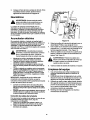
Adjusting
1.
2.
3.
4.
5.
6.
7.
Changing Belt
Shift Linkage
Inspect the shift linkage for damage or wear.
Disengage the parking break and push the vehicle
back and forth to verify that it is in neutral.
Remove hairpin clip and washer securing ferrule to
the shift rod. See Figure 24. Loosen the jam nut.
Rotate ferrule towards the start of the threads to
adjust forward engagement.
Rotate ferrule towards end of the threads to adjust
reverse engagement.
Once the engagement is adjusted, tighten the jam
nut. Insert ferrule into shift rod and secure with
washer and hairpin clip, removed in step 3.
Move shift rod to (N) and check for correct
adjustment.
WARNING:
Be sure to shut the engine off,
remove ignition key, disconnect the spark plug
wire and ground against the engine to prevent
unintended starting before removing belt(s).
NOTE: Proper removal of the belt requires the removal
of several other components by means of special tools.
Read through the following procedure and determine if
you can successfully complete it prior to attempting;
otherwise contact a Sears service center.
IMPORTANT:The V-belts, used on this vehicle, are
specially designed to engage and disengage safely. A
substitute (non-OEM) V-belt can be dangerous by not
20
disengaging
completely.
Fora properworkingmachine,
usebeltsavailablefromSears.
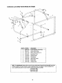
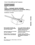
1.
2.
Follow Figure 25 for routing of belts and pulleys.
Periodically check to see if these belts are too loose
or damaged through wear and tear. If so, replace
with new belt.
NOTE:
It is recommended
Replace with new belt making sure that the
hardware is propedy secured and the belts are on
the inside of the belt keepers.
Jack Spindle Replacement
Check jack spindle whenever you replace upper deck
drive belts. If the jack spindle does not spin freely when
the belts are disengaged, it should be replaced.
that both drive belts be
replaced at the same time.
1.
2.
Special tools required: Vise grips or impact wrench.
_--
8.
3.
4.
Engine Pulley
5.
6.
Idler
7.
PulleyJ
Disconnect and ground the spark plug wire.
Unhook both straps securing grass catcher to the
vehicle frame. Remove grass catcher from unit and
keep it aside.
Flip the utility bed up to access the jack spindle.
Loosen the jack spindle pulley bolt using a pair of
wrenches. See Figure 26.
Remove the pulley from the jack spindle.
Remove four screws (only two called out in Figure
26) that secure jack spindle to the vehicle frame.
Remove the jack spindle.
Flat Idler X(
_Pulley
Bolt
" Transmissiol
Spin
Brak
_/f
Jack Pulley
Spindle
Idlel
Figure 25
Upper Deck
I.
2.
3.
4.
5.
6.
7.
Drive
Figure 26 ....
Belt
8.
Engage the parking brake and tum the ignition off.
Remove the cutting deck as instructed in the
previous section.
Disconnect spindle brake bar at the idler pulley.
Note the hardware positions for future use.
Remove the lower deck belt tension pulley arm. Do
not remove the spring. Note hardware position.
Using a 9/16" socket, remove the bolt holding the
engine pulley, and drop the pulley down. To loosen
this bolt, you will have to hold the engine shaft
firmly with vise grips at a point closest to the bottom
of the vehicle frame. This will stop the shaft from
rotating, and help in removing the engine pulley.
Roll the belt off the engine pulley.
Slip the belt off from the idler pulley. Remove the
belt from the jack pulley.
Replace with a new jack spindle and re-attach to
the frame.
9.
Working under the vehicle, re-install the jack
spindle pulley with the bolt removed earlier.
10. Flip the utilitybed back to the operating position, reattach grass catcher as needed, and re-connect the
spark plug wire.
Drive Belt
IMPORTANT:When either or both of the drive belts are
worn off, replace both. Replacing only one willaffect the
performance of your lawn utility vehicle.
NOTE: It may be necessary to adjust the speed control
linkage after replacing both drive belts.
1.
21
Remove the cutting deck.
2.
3.
4.
,
5.
6.
7.
8.
Remove the upper drive belt first by working from
the back of the unit. Roll the belt off the idler pulley
first and then off the transmission pulley. Next roll it
off the variable speed pulley.
Working from the side of the unit, pull the lower
drive belt tension pulley to the right and roll the
lower drive belt off this pulley.
Using a 9/16 socket, remove the bolt holding the
engine pulley, and drop the pulley down. To loosen
this bolt, you will have to hold the engine shaft
firmly with vise grips at a point closest to the bottom
of the vehicle frame. This will stop the shaft from
rotating, and will facilitate in removing the engine
pulley.
Remove the belt from the two idler pulleys.
Remove the belt from the variable speed pulley and
the transmission pulley.
Replace upper deck drive belts following earlier
instructions.
NOTE: While re-attaching the lower deck belt tension
pulley ann, make sure the spring does not fall off. To
check that the spring is attached correctly, pivot the
utility bed up and you should see one end of the spring
hooked to the larger of the two holes on the bed.
Replace the drive belt. When re-installing the belt,
make sure belts are on the inside of the three belt
keepers. See Figure 27.
Belt
Keeper
Figure 27
22
If the lawn utility vehicle is to be inoperative for a period
longer than 30 days, follow the steps below for storage.
2.
Preparing for Storage
3.
Battery
1. Fully charge the battery with a 6 amp battery
charger. NEVER store battery without a full charge.
4.
NOTE: ff a charger with 6 amp output is not available, a
lower output charger may be used for a longer period of
time. Do not charge the battery at a rate higher than 6
amps as it can damage the battery and reduce its life.
2.
3.
Equipment
1. Clean entire unit thoroughly.
2: Lubricate all pivot points, Wipe the entire machine
with an oiled rag to protect the surfaces.
When storing unit for extended periods, disconnect
battery cables and remove the battery from the unit.
Keep the terminals and the top of the battery clean
and free from corrosion. Clean the battery with
baking soda or a commercial battery cleaner.
Storing the Equipment
1.
IMPORTANT:Do not allow any cleaning solution to get
inside the battery.
2.
Engine
1.
adding, to circulate the additive through the
carburetor. Refer to page 11 for details on
additives.
While the engine is stillwarm, change oil. Refer to
instructions on page 15.
Remove spark plug and pour about 0.5oz. or 15mL
of engine oil into cylinder. Replace spark plug and
crank engine slowly to distribute the oil.
Remove any debris or grass clippings from the
surface of the engine.
To prevent gum from forming in fuel system or on
carburetor parts during storage, follow the
apprepriate step from those listed below:
a. If fuel tank contains oxygenated or
reformulated gasoline (gasoline blended with
alcohol or ether), run engine until the gas
tank is dry.
b. If fuel tank contains gasoline only, run engine
until the gas tank is dry.
c. If a gasoline additive is being added to the
gas, run engine for several minutes, after
Store unit in a clean, dry area. Do not store next to
corrosive materials, such as fertilizer.
When storing any type of power equipment in an
unventilated or metal storage shed, rustproof the
equipment. Using a light oil or silicone, coat the
equipment, especially any chains, springs,
beadngs and cables.
After Storage
The battery loses some of its charge each day when the
unit is not used. Recharge battery before returning to
service or every two months, whichever occurs first.
NOTE: If a charger is not available but the battery will
start the lawn utilib/ vehicle, the battery will be charged
by mowing for a minimum of one hour.
23
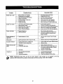
Trouble
Engine
failstostart
PossibleCause
RemedialAction
Fuel tank empty, or stale fuel.
Blocked fuel line.
Faulty spark plug.
1.
2.
3.
4.
5.
6.
7.
Disengage blade control lever
Engage parking brake.
Connect wire(s) to spark plug.
Pull out the CHOKE control
Fill tank with clean, fresh gasoline.
Clean fuel line or replace fuel filter
Clean, adjust gap or replace spark plug.
1.
2.
3.
4.
5.
Unit running with CHOKE applied.
Spark plug wire loose.
Blocked fuel line or stale fuel.
Vent in gas cap plugged.
Water or dirt in fuel system.
1.
2.
3.
4.
5.
Push CHOKE control in.
Connect and tighten spark plug wire.
Clean fuel line; fill tank with fresh gasoline.
Clear vent or replace cap if damaged.
Drain fuel tank. Refill with fresh gasoline.
Engine overheats
1.
2.
Engine oil level low.
Air flow restricted.
1.
2.
Fill crankcase with correct oil.
Clean grass clippings and debris from
around the engine's cooling fins and
blower housing.
Engine hesitates at
high RPM
1.
Spark plug gap too close.
1.
Remove spark plug end reset the gap
to.030".
Idles poorly
1.
Spark plug fouled, faulty or gap too wide.
1.
Replace spark plug. Set plug gap to.030".
Excessive vibration
1.
2.
Cutting blade loose or unbalanced,
Damaged or bent cutting blade.
Mower will not mulch
grass
1.
2.
Wet grass.
Excessively high grass.
1.
2.
3.
Dull blade.
3.
Wait until grass is dry to cut.
Mow once at a high cutting height, then
mow again at desired height or make a
narrower cutting swath.
Sharpen or replace blade.
1.
2.
3.
Deck not balanced properly.
Dull blade.
Uneven til'e pressure.
1.
2.
3.
Level the deck side to side.
Sharpen or replace blade.
Check tire pressure in all four tires.
1.
2.
3.
4.
Blade control lever engaged.
Parking brake not engaged.
Spark plug wire(s) disconnected.
Choke not activated
5.
6.
7.
Engine runs erratic
Uneven cut
i 1.
2.
Tighten blade and spindle. Balance blade.
Replace blade.
problems not mentioned here, please contact Sears service by calling 1-800-4-MY-HOME®.
NOTE: Suggestions listed hero are only for minor repairs, ff the problem is not resolved, or for any
24
Parts List for Craftsman
For
\
Lawn Utility Vehicle Model 247.270250
33
15
\
For reference
only
only
45
3\
For
reference
only*
\
NOTE: For painted
parts, please refer
to the list of color
codes below. Please
add the applicable
color code, wherever needed, to the
part numbar to order
a replacement part.
For instance, if a
part, numbered 700xxxx, is painted polo
green, the part number to order would
be 700-xxxx-0689.
Polo Green: 0689
Powder Black: 0637
Oyster Gray: 0662
51
Choke mounts
to seat plate
103
'_
41
\
76
104
• For cladty of viewing, these parts have been referred to more than once in this illustration.
25
59
Parts List for Craftsman
Lawn Utility Vehicle
Description
Steedng Wheel
Steering Wheel Cap
Key No.
1.
Part No.
731-1687
2.
3.
731-t459A
647-0055
4.
5.
683-0432
683-0433
6.
7.
683-0592
710-0191
8,
710-0599
9,
10.
710-0604A
710-0859
11,
710-1017
12.
13.
710-1681
710-3013
Hex Bolt
14.
15.
711-0242
711-0396
Spacer
16.
17.
711-1155
711-1531
18.
19.
712-0296
712-0380
20.
21.
712-0431
712-0692
22.
712-0714
23.
24.
712-3007
712-3017
25.
26.
714-0104
714-0145
27.
28.
714-0149B
714-0470
29.
30.
720-0232
720-0269
31.
32.
726-0272
732-0445
33.
34,
732-0594A
732-1167
35.
732-3091
36.
37.
Model 247.270250
Key No.
53.
Part No.
746-1129
54.
55.
747-1228A
747-1240
Ddve Pedal Assembly
Brake Pedal Assembly
Idler Brake Assembly
Hex Bolt 3/8-24 x 1.25"
56.
57,
747-1249
747-1254
58.
59.
747-1255
747-04024
]-r Screw 1/4-20 x 0.5"
TT Screw 5/16-18 x 0.625"
60,
747-1262
61.
62.
783-1142
783-1253
63.
783-1287
64.
65.
783-1293
783-1307
66.
67.
650-0007
683-0033A
68.
69.
683-0178A
683-0179A
70.
710-0459A
Flange Lock Nut 1/4-28
Flange Lock Nut 3/8-16
71,
72.
710-0643
710-0689
Nylon Lock Nut
73.
74,
710-0837
710-0958
Shift Pivot Assembly
Hex Bolt 3/8-16 x 2.5"
AB Screw 1/4-14 x 0.625"
Hex Bolt 1/4-20 x 0.50"
Spacer
Ferrule
Shaft
Jam Nut 3/8-24
Flange Lock Nut 5/16-18
Jam Nut 5/16-18
Oescription
Brake Cable
Shift Rod
Variable Control Rod
Control Rod
Shift Rod
PTO Lever
Brake Lock -Out Red
Belt Keeper Rod
Shift Switch Bracket
IShift Index Bracket
Brake Mounting Bracket
Cont. Bracket: PTO
Link Bracket
Steering Tube Assembly
Steering Support Bracket Assembly
Front Axle RH
Front Axle LH
Hex Bolt 3/8-24 x 1.5"
Hex Bolt 5/16-18 x 1,0"
Hex Bolt 1/2-13 x 0.75"
A.BScrew #10-16 x 0,625"
Hex Bolt 1/4-20 x 1.25"
76.
712-0116
Jam Lock Nut 3/8-24
Hex Nut 3/8-16
Cotter Pin
77.
78.
712-0206
712-0241
Click Pin
79.
80.
712-0324
712-0411
Hex Nut 1/2-13
Hex Nut 3/8-24
Hex Lock Nut 1/4-20
81.
712-0692
84.
85.
723-0156
731-0559B
86.
89.
736-0105
736-0196
90.
736-0242
Bell Washer ,340 x ,872 x .060
91.
92.
736-0272
736-032O
Flat Washer .510 x 1.0 x .060
Flat Washer 3/8 x 1.37
735-0283
735-3049
Compression Spring
Compression Spdng
Drive Pad
Brake Pad
93.
94.
736-3078
738-0541
Flat Washer ,344 x 1.0 x .063
38.
39.
736.0146
736-0160
Lock Washer
Flat Washer.53 x .93 x .050
95.
738-3089A
736-0169
736-0187
Lock Washer 3/8
Flat Washer
741-0225
741-0356
747-0955
Steering Adapter
Hex Flange Bearing
40.
41,
96.
97.
98.
42.
43.
736-0267
736-0270
Flat Washer
Bell Washer
99,
748-0290
Pinion Gear
44.
45.
736-0314
736-0701
Thrust Washer
100,
101,
102.
750-O532
783-1302
783-1129
Spacer
Steering Gear
46,
736-0734
103.
634-0169A
47.
48.
738-0183
738-0347
49.
50.
51.
738,-0826
741-0495
746-1089
104.
634-0170A
734-0255
741-0487A
741-0706
714-0115
52.
746-1127
• Not shownin illustration
Hairpin Clip
Cotter Pin
Shift Knob
Clutch Grip
Clamp
Extension Spring
Extension Spring
Flat Washer
Flat Washer
Shoulder Screw ,50 x ,21 : 3/8-16
Shoulder Spacer
Shoulder Screw 1/4-28 x .375
Flange Bearing
Choke Control
Deck Cable
26
Hex Lock Nut 5/16-24
Hex Lock Nut
Bail Joint 3/8-24
Steering Bellow
Bell Washer
Flat Washer.628 x 1.56 x .036
Spacer
Beadng: Steering Column
iTie Rod
3over: Steering Column
Complete Wheel Assembly: Front
Rim Assembly*
Valve*
FI. Bearing*
FI. Bearing*
Cotter Pin
Parts List for Craftsman
Lawn Utility Vehicle
Model 247.270250
16
For reference only
/
11
IMPORTANT:
For a proper
working
machine, use Factory Approved Parts.
V-BELTS are specially designed to engage
and disengage safely. A substitute (non
OEM) V-Belt can be dangerous by not
disengaging completely.
NOTE: For painted parts, please refer to
the listof color codes below. Please add the
applicable color code, wherever needed, to
the part number to order a replacement
part. For instance, if a part, numbered 700xxxx, is painted polo green, the part number
to order would be 700-xxxx-0689.
Polo Green: 0689
Powder Black: 0637
Oyster Gray: 0662
14
27
Parts List for Craftsman
Key No. Pert No,
618-04007
1.
Lawn Utility Vehicle Model 247.270250
Key No.
Part No.
Transmission Assembly*
25.
736-0169
Description
Lock Washer 3/8
Description
2.
619-0011
Spindle Housing
26.
736-0219
Bell Washer .39 x 1.13 x .062
3.
683-0446
Idler Bracket Assembly
27.
736-0247
Flat Washer 3/8 x 1.25"
4.
683-0447
Idler Bracket Assembly
28,
736-0427
Bell Washer .567 x 1.128 x .06
5,
710-0191
Hex Bolt 3/8-24 x 1,25"
29,
736-3052
Flat Washer .406 x 1.0 x. 105
6.
710-0459A
Hex Bolt 3/8-24 x 1.50"
30.
738-0155
Shoulder Screw
7.
710-0521
Hex Bolt 3/8-16 x 3,0"
31.
738-0347
Shoulder Spacer
8.
710-0539
Hex Bolt 3/8-24 x 1,75"
32.
738-0968
Shoulder Spacer
9.
710-0650
TT Screw 5/16-18 x 0.875"
33.
741-0405
Thrust Bearing
10.
710-0902
Hex Screw 3/8-24 x 3,75"
34.
741-0919
Ball Bearing
11.
710-1039
Hex Screw 3/8-24 x 1.0"
35.
750-0705
Sleeve Spacer
12.
710-1812
Hex Screw M20 x 2.5:180
36,
750-0952
Spacer
13.
712-0241
Hex Nut 3/8-24
37.
754-0453
Belt: V Type
14.
712-0296
lam Lock Nut 3/8-24
38.
754-0493
Belt: V Type
15.
712-0695
Hex Flange Nut M20 x 2.5
39.
754-0494
Belt: V Type
16.
712-3004A
Flange Lock Nut 5/16-18
40.
756-0650
Transmission Pulley
17.
18.
712-3017
Hex Nut 3/8-16
41.
756-0981A
Flat idler Pulley
712-3035
Jam Nut 9/16-18
42.
756-1195
Jack Pulley: Double
19.
714-0133
Key
43.
756-1200
Engine Pulley: Double
20.
717-0884
Variable Speed Pulley Assembly
44.
756-1207
Idler Pulley
21.
732-0308
Extension Spring
45.
783-0528
Idler Bracket: Variable Speed
22.
732-0418
Extension Spring
46.
783-1292
Cable Bracket
23.
732-0814
Extension Spring
47.
783-1341
Bracket: Lock: Pedal
24.
736-0101
Flat Washer .406 x 1.0 x ,030
* For full break-down of the transmission assembly, see page 34.
Key No.
1,
Part No.
634-0212
Description
634-0211
Rim Assembly
Valve
734-0255
734-0298
Rear Wheel Assembly Complete: 13 x 5 x 6
2,
736-0242
Flange Bearing
Bell Washer .340 x ,872 x ,060
3.
710-0627
Hex Bolt 5116-24 x .750
28
Parts List for Craftsman
Lawn Utility Vehicle Model 247.270250
48
5O
I
2O
I
I
I
I
NOTE: For painted
parts, please refer to
the list of color codes
below. Please add
the applicable color
code, wherever
needed, to the part
number to order a
replacement part. For
instance, if a part,
numbered 700-xxxx,
is painted polo green,
the part number to
order would be 700xxxx-0689.
Polo Green: 0689
Powder Black: 0637
Oyster Gray: 0662
I
I
Iii
llq
111
III
IL_
75
47
/
49
1
32
For reference only_
29
Parts List for Craftsman
Lawn Utility Vehicle Model 247.270250
Key No.
1.
Pert No.
757-04000
Description
_eat
2.
683-0575
Support Bracket Assembly LH
3.
683-0576
Support Bracket Assembly RH
Key No. Part No.
710-1752
38,
39.
711-1165
'12-0185
Description
Special Screw
Clevis Pin
Speed Nut 1/4-20 *
4.
710-0604A
TT Screw 5/16-18 x 0.625"
40.
42.
5.
710-1250
Carriage Boll 5/16 x 1.5"
43.
712-0692
Hex Lock Nut
Flange Lock Nut
712-0640
Hex Nut
6.
710-1681
Hex Bolt M8-1.25: 20
44.
712-0714
7.
710-1690
Special Screw M6-1:16
Hex Bolt M8-1,25: 45
45.
714-0470
Cotter Pin
46.
723-0491
Tray
723-0604
Foot Pad
8.
710-1703
9.
712-0431
Flange Lock Nut 3/8-16
47.
10.
712-0689
Hex Nut M6-1
48.
728-0285
Rivet
11.
712-0692
Hex Lock Nut M8-1.25
49.
731-04013
Battery Cover*
12.
712-3004A
Flange Lock Nut 5/16-18
50.
731-2360
Bag Tray
13,
726-3046
Ratchet Clip
51.
736-0187
Flat Washer .64 x 1.24 x .06
14.
732-0735
Compression Spdng
52.
736-0700
Flat Washer 8.4 x 16
15.
732-0750A
Actuator Spring
53.
736-0765
Lock Washer M4
16.
732-0996
Compression
Spdng
55.
750-1293
Spacer
Spring
56.
783-04004
Bracket: Battery Support
17.
732-0997
Compression
18.
736-0105
Bell Washer .375 x .870 x .063
57.
783-1081A
Frame
783-1097
Rear Bracket: Pivot Support
19.
736-0289
Shoulder Bushing
58.
20.
736-0648
Lock Washer
59.
783-1101
Support Bracket: Transmission
21.
736-0743
Flat Washer 8.4 x 35
60.
783-1148
Chute Bracket
22.
738-1014
Shoulder Screw
61.
783-1260
Stop Bracket: Pivot
Cable Bracket
23.
749-1264
Support Tube: Seat
62.
783-1292
24.
783-04005
Seat Bracket
63.
710-O654A
TT Seres Screw 3/8-16 x 1.0
Bell Keeper Bracket
25.
783-0733
Spacer
64.
783-1294
26.
783-0931
Bag Switch Bracket
65.
710-1683
Hex Bolt M8-1.25: 30
Pin: Belt Guard
27.
783-1118A
Seat Support Bracket
66.
'11-1065
28.
17962
Switch Plate
67.
712-0692
Lock Nut M8-1.25
Hex Nut 5/16-18
29.
683-0142
Pivot Bar Assembly
68,
712-3010
30.
683-0581
Support Bracket Assembly RH
722-0153
31.
;683-0591
Bracket Assembly: Steedng Columr
69.
70.
736-0119
Engine Mount: Gromm.
Lock Washer 5/16
32.
583-0593
Pivot Support Bracket: Front
71.
736-0701
Flat Washer 8.4 x 24
33.
710-0224
Ab Screw #10-16 x 0.5"
72.
747-1292
Belt Keeper Rod
34.
710-0599
TT Screw 1/4-20 x 0.5"
73.
750-0539
Spacer
35.
710-0946
Machine Screw *
74.
783-1120
Mounting Plate
36.
710-1681
Hex Screw M8-1.25:20
75.
725-1698
Battery*
37.
710-1708
Special Screw
76.
710-0870
Self-Tapping Screw
* If equipped
30
Parts List for Craftsman
Lawn Utility Vehicle Model 247.270250
5
J
/
11
47
46
For reference
only
31
42
43
NOTE: For painted parts, please refer to the list of color codes below. Please add the applicable color
code, wherever needed, to the part number to order a replacement part. For instance, if a part, numbered 700-xxxx, is painted polo green, the part number to order would be 700-xxxx-0689.
Polo Green: 0689
Powder Black: 0637
Oyster Gray: 0662
31
Parts List for Craftsman
Key No.
1.
2,
Lawn Utility Vehicle Model 247.270250
Part No.
Description
Key No.
Part No.
683-0441
Shift Assembly: Front Lift
25.
783-1082
Description
Deck
_83..0442
Pivot Bracket Assembly
26.
710-0347
Hex Screw 3/8-16 x 1.75
_83-0448
Bracket Assembly: Lift Handle
27.
710-0514
Hex Bolt 3/8-16 x 1.0
4,
710-0641
Hex Bolt 1/4-20 x 2.25
28,
710-0650
"17"Screw 5/16-18 x 0,875
5.
710-1681
Hex Bolt M8-1,25: 20
30.
712-0417A
Flange Nut 5/8-18
6.
711-0832
Ferrule
31.
712-3017
Hex Nut 3/8-16
7.
712-0431
Flange Lock Nut 3/8-16
32.
726-0365
8.
712-0692
Hex Lock Nut M8-1.25
33.
731-2361A
Speed Nut
Grass Catcher Chute
Side-Discharge Chute
3.
9.
712-3027
Lock Nut 1/4-20
34.
731-2477
10.
714-0104
Hairpin Clip
35.
731-2505
Mulch Plug
11.
716-0106
E-Ring
36.
732-0814
;Extension Spring
12.
731-2509
Handle Grip
37.
736-0169
Lock Washer
13.
732-1020
Torsion Spring
38,
736-0701
Flat Washer 8.4 x 24
14.
736-0314
Thrust Washer .375 x .70 x .030
39,
738-0933
Spindle Shaft
15.
736.-0336
Flat Washer 5/8 x 1.0 x .030
40,
738-0968
Shoulder Spacer
16.
736-0341B
Flange Washer ,633 x .883
41.
741-0919
Ball Bearing
17.
736-3010
Flat Washer ,407 x ,812 x .135
42.
742-0667
Blade: Bagging
18.
738-0281
Shoulder Screw .625 x. 17:3/8-16
43.
742-0760
Blade: 3-in-1
19.
747-1247
Lift Link
44.
750-1000
Spacer
20.
750-0566A
Spacer
45.
754-0495
Belt: V Type
21.
783-1136
Upper Lift Link Bracket
46.
756-0969
Deck Pulley
22.
783-1138
Lift Hanger Bracket
47.
756-0981A
Flat Idler Pulley
23,
783-1143
Lift Indx. Bracket
48,
783-1122
Idler Bracket: Deck
24.
619-0020
Spindle Housing
32
Craftsman
Lawn Utility Vehicle Model 247.270250
3
\
I
I
j6
Key No.
1.
Part NO.
649-0126
Description
Tube Assembly: Front Frame
2.
664-0107
Grass Catcher Bag
3.
710-1194
Mach. Screw #10-24 x 1.0
4.
712-0161
Lock Nut #10-24
5.
723-0383
Retainer Strap
6.
736-0400
Flat Washer
7.
749-1260
Side Tube: Frame
8.
749-1262
Bag Handle
9.
749-1269
Support Tube
NOTE: For painted parts, please refer to the list of color codes below. Please add the applicable color code,
wherever needed, to the part number to order a replacement part. For instance, if a part, numbered 700xxxx, is painted polo green, the part number to order would be 700-xxxx-0689.
Polo Green: 0689
Powder Black: 0637
Oyster Gray: 0662
33
Parts List for Craftsman
Lawn Utility Vehicle Model 247.270250
1
®
2
/
I0
Key No. Part No.
1.
611-0011
Description
Shaft Assembly: Detent
2.
618-0072B
Upper Housing Assembly
3.
610-0135
Drive Shaft Assembly: LH Brake
4.
61 0-04009
Axle Assembly
5.
661-0043
Brake Assembly: Yoke LH
6.
710-1325
TT Screw 1/4-20 x 1.625"
7.
8.
717-0678
Break Pad
719-0313B
Lower Housing
9.
732-0863
Spring Detent
10.
737-0148
Grease
11.
741-0862
Ball: Detent: .250
12.
761-0202
Brake Disc
13.
618-04007
Transmission Assembly Complete:
Single Speed
34
E
ENGINE
MODULE
u
0
(1
729-0352
_
SEAT
SWITCH
_
Connector
Connector
'
-
_
JL
"
_-_
a
BRAKE
Connector
729-0148
SWITCH
_
I
.J
o
125
7L_.._59
Connector
'M
O
C_n_r
7"_-0148
BAG
SWITCH
Connector
729-0148
Connector
Connector
7290147
125
PTO
SWITCH
REVERSE
SWITCH
KEY
SWITCH
0
Parts List for Craftsman
Lawn Utility Vehicle Model 247.270250
Safety & Decorative Labels
777006242
ON STEERING
(MODEL
PLATE
ON RIGHT
CAP
SIDE)
777122019
777S32028
777D06237
777S32029
777120887
777122016
777120889
|
777122020
777D06240
777120890
777D06241
777S30018
777D06238
@
Some of these symbols will be found
on the engine or in the manual or
labels on the lawn utility vehicle. Interpret
them as indicated here, and follow
the message,
777D06239
Fire
Fuel
Moving Parts
@
I'-,I
Stop
Oil
Explosion
Choke
Hot Surface
Read Owner's
]_
Toxic Fumes
_1_
Kickback
Shock
36
Manua,
Fuel Shutoff
'_
Primer
Parts List for Briggs & Stratton
Engine 12607-0324
for Lawn Utility Vehicle Model 247.270250
684 9
10
238
1029_
_
1034
337_
383
914_
5o5@
307
616
718_
L 1019 KIT-LABEL
29
32,=q_
24_
146
1095 VALVE GASKET SET
883 (_
868_
_
1022
163_
15 _
37
20_
J
Parts List for Briggs & Stratton
Engine 12607-0324
for Lawn Utility Vehicle Model 247.270250
365%
445_
188_
190_
613A_
_13_
883_
977 CARBURETOR
524
sl
_
GASKET
SET
"3A°s
? 633®
163_
38
J\_836A
_
Parts List for Briggs & Stratton
Engine 12607-0324
for Lawn Utility Vehicle Model 247.270250
121 CARBURETOR OVERHAUL KIT
309_ 5101742_
6330
127_
104_'
276 _
51_
937_
163
784_
633A_
51A_
134_
651t
785_'_J_7"
Aa
513_)
oo
1370
803_
310_
553%502
305_
930A_
930_
I 1036 LABEL-EMISSION
332_
I
455@
1005_
39
Parts List for Briggs & Stratton
Key No.
1
PaN No.
Description
897639
Engine 12607-0324
2
399269
Cylinder Assembly
Kit: Bushing Seal
for Lawn Utility Vehicle Model 247.270250
Key No. IPart No.
1498975
118
592703
121
694203
125
Description
Jet-Main (High Altitude)
Kit: Carburetor Overhaul
3
299619
Oil Seal (Magneto Side)
4
499619
Sump: Engine
127
594468
5
695276
Head: Cylinder
130
591203
7
B97230
Gasket: Cylinder Head
133
_398187
8
495786
Kit: Needle/seat
272481
134
137
398188
9
Breather Assembly
Gasket: Breather
593981
Gasket: Float Bowl
t0
691125
Screw ( Breather Assembly)
146
590979
11
Tube: Breather
Gasket: Crankcase
163
187
591894
Key: Timing
Gasket: Air Cleaner
12
B91260
692232
691050
Fuel Line
13
691137
Screw (Cylinder Head)
188
691147
Screw (Control Bracket)
16
691680
691467
Plug: Oil Drain
Crankshaft
190
192
590940
16
594543
Screw (Fuel Tank)
Ball: Rocker Arm
20
399781
Oil Seal (Pto Side)
202
591303
Link: Mechanincal Governor
22
591092
Screw (Engine Sump)
209
691290
23
697637
Flywheel
222
592723
Spring: Governor
Control Bracket
24
222698
Flywheel Key
227
591467
Lever: Governor Control
25
499627
692788
Piston Assembly (Standard)
238
691300
Cap: Valve
Piston Assembly (.010" Oversized)
259
591189
Bracket: Casing Clamp
B92789
Piston Assembly (.020" Oversized)
276
Washer: Sealing
692790
Piston Assembly (.030" Oversized)
Ring Set (Standard)
287
300
271716
690940
Ring Set (.010" Oversized)
Ring Set (.020" Oversized)
304
305
499676
691108
Blower Housing
Screw (Blower Housing)
Ring Set (.030" Oversized)
Piston Pin Lock
306
307
591232
Shield: Cylinder
590345
Screw: Cylinder Shield
Starter Motor
26
499631
692785
$92786
692787
594248
Carburetor
Plug: Welch
Valve: Throttle
Float: Carburetor
Screw (Dipstik Tube)
Muffler
27
691866
28
499423
Piston Pin (Standard)
309
695550
29
499424
Connecting Rod
310
892327
Bolt (Starter Motor)
32
Screw: Connecting Rod
332
590662
Nut (Flywheel)
32.A
691664
695759
Armature: Magneto
499642
333
334
802574
33
Screw: Connecting Rod
Exhaust Valve
691061
Screw: Magneto Armature)
34
499641
Intake Valve
337
692051
Spark Plug
35
691304
Spring: Intake Valve
356
692151
Stop Wire
36
691304
692194
358
363
694090
4O
Spring: Exhaust Valve
Retainer: Valve
19069
Gasket Set: Engine
Flywheel Puller
43
45
691997
Slinger--
365
691136
Screw (Carburetor)
690977
Spark Plug Wrench
690272
Washer (Governor Crank)
51
694039
692668
383
404
19374
46
Tappet: Valve
Camshaft
IGasket: Intake
443
690255
Screw (Air Cleaner Primer Base)
51A
692799
Gasket: Intake
445
697029
73
691221
95
691636
Screen: Rotating
Screw: Throttle Valve
455
474
695161
695730
Filter: Air Cleaner Cartridge
Flywheel Cup
Alternator
97
499681
Shaft: Throttle
505
231082
104
691242
Pin: Float Hinge
510
494147
Nut (Governor Control Lever)
Drive: Starter
108
691182
499681
Valve: Choke
513
692358
Drive Clutch
109
Shaft: Choke
523
499621
Dipstick
117
498978
Jet-Main (Standard)
524
692296
Seal: O-Ring
Govemor/oil
40
Parts List for Briggs & Stratton
Key No,
525
Part No.
495265
Engine 12607-0324
Description
for Lawn Utility Vehicle Model 247.270250
Key No.
Dipstick Tube
Grommet
Part No.
Description
Muffler Guard
832
836
691466
607551
836A
842
691147
691031
Screw (Muffler Guard)
Washer Set
847
692047
Dipstick Tube Assembly
94852
Bolt (Governor Control Lever)
851
493880
692342
Cover: Breather Passage
868
692044
Spark Plug Terminal
Valve Seal
585
691879
Gasket: Breather Passage
883
691893
Exhaust Gasket
601
95162
Ho6e Clamp
886
696268
Gasket Kit: Cylinder Head/Plate
613
691140
Screw (Exhaust Muffler)
914
691108
613A
691108
616
690340
Screw (Exhaust Muffler)
Retainer: Governor Shaft
930
930A
691919
499679
Screw (Rocker Cover)
Suard: Rewind
937
691325
Spline: Starter
529
692937
534
690244
544
690786
Screw (Air Cleaner Cover)
Armature: Starter
545
492919
562
584
Screw (Muffler Guard)
Seat: O-ring
Guard: Rewind
616
691306
Crank: Governor
619
691108
633
691321
Screw (Cylinder Head Plate)
Seal: Choke/throttle Shaft
957
966
692046
690243
Fuel Tank Cap
Base: Air Cleaner Primer
633A
693867
Seal: Choke/throttle Shaft
967
273356
Filter: Pre-Cleaner
635
66538
Spark Plug Soot
968
692435
Air Cleaner Cover
651
690345
Screw (Starter Gear Cover)
972
499618
Fuel Tank
670
692294
Spacer (Fuel Tank)
975
493640
Float Bowl
684
690345
IScrew (Breather Passage Cover)
976
694395
Primer
692
690572
Spring: Detent
977
692704
Gasket Set: Carburetor
697
691127
Screw (Ddve Cap)
993
694088
Gasket: Cylinder Head Plate
718
690959
Pin: Locating
1005
691346
741
691830
Sear: Timing
1019
499691
Fan: Flywheel
Label Kit
742
93941
691918
Retainer: E-Ring
Gear: Pinion 19T
1022
1023
691890
499624
Gasket: Rocker Cover
783
783A
691269
Gear: Pinion 12T
1026
._92045
Push Rod
784
692341
Cover: Starter Gear
1029
691230
Rocker Arm
785
692352
Gasket: Starter Cover
1034
1691343
Guide: Push Rod
801
690782
Cap: Drive
1036
_96767
Emission Label
802
695267
End Cap
1059
692311
Screw/Washer Kit
803
695266
Starter Housing
1095
594091
Set: Valve Gasket
830
694544
Stud (Rocker Arm)
1119
691183
Screw (Alternator)
41
Rocker Cover
|ndice de materias
Pdgina
|ndice de materias
Pdgina
Mantenimiento ........................................ 54
Informacibn sobre la garantfa ................... 42
Prdcticas de funcionamiento seguras ...... 43
Determinacibn de la pendiente ................ 46
Monta}e .....................................................
47
Funcionamiento ........................................ 49
Servicio y ajustes ...................................
58
Almacenamiento prolongado.................. 62
Resoluci6n de problemas ....................... 63
Informacidn de la ayuda de cliente ......... 64
GARANT[A LIMITADA SOBRE EL VEH[CULO UTILITARIO CORTACI_SPED
Pot dos (2) afios a partir de la fecha de compra, sial equipo de monta e Craftsman se le da mantenimiento, lubricacibn y
afinacidn de acuerdo con las instmcciones en el manua del prop etario, Sears reparard o reemp azard libre de cargo
cualquier pieza que est6 defectuosa en material y mano de obra de acuerdo con la gufa de cobertura que se describe rods
abajo.
Sears proporcionard tambidn sin costo en la mano de obra aqueUas piezas en garantia por los dos afios cornpletos. Durante
los primeros 30 dfas a partir de la fecha de compra, no habrd cargos por dar servicio al producto en su domicillo para aquello
que est_ cubierlo en esta garantl'a. (Vea las excepciones rods abajo).
Para su conveniencia, el servicio de garantfa EN SU CASA estard disponible despu_Ys de los primeros 30 dfas de la fecha de
compra, pero se le hard un cargo por gastos de transporte. Este cargo no se realizard si el producto Craftsman se Ileva hasta
un osntro autorizado de Sears. Para conocer el centro autorizado Sears m_s carcano, por favor Ilame al 1-800-4-MYHome(r). Esta garantfa tiene validez dnicamente mientras el producto estd en los Estados Unidos.
EXCLUSION
Esta garantfa no cubre:
•
Artfculos de duracidn limitada que sufren desgaste bajo condiclones normales de uso, incluyendo sin limitaciones las
cuchillas, bujfas de encendido, pudficadores de aire, correas y filtros de aceite.
Serviclo normal de mantenimiento, camblo de aceite o afinaclones.
•
Reemplazo o reparacibn de neum_ticos debido a pinchaduras causadas por objetos externos, tales como clavos, espinas,
tocones o vidrio.
Reparaciones necesarias debido al abuso del operador, incluyendo pero sin limitarse a dafio causado pot cargar objetos
mds alld de la capacidad de carga del equipo o por objetos que hacen impacto que puedan doblar la estructura o el eje del
cig0efial o puedan sobreacelerar el motor.
Reparaciones necesarias debido a negligencia del operador, incluyendo pero sin limitarse a dafios el_ctricos y mecdnicos
causados por almacanamiento incorrecto, falla en la calidad o cantidad del aceite de motor utilizado, falla para mantener la
cubierta libre de desechos inflamables, o falla para mantener el equipo de acuerdo con las instrucciones contenidas en el
manual del propietario.
•
Limpieza o reparaciones del (sistema de combustible del) motor causadas por combustible que se encontr6 que estaba
contaminado u oxidado (vencido). Por lo general, el combustible debe utilizarse dentro de los 30 dias posteriores a la fecha
de compra.
•
Deterioro y desgaste normal de los acabados exteriores o reemplazo de etiquetas del producto.
Equipos utUizados para fines comerciales o de alquiler.
GARANT[A LIMITADA SOBRE EL ACUMULADOR
ELt_CTRICO
Por noventa (90) dfas a partir de la fecha de compra, si cualquier acumulador el(_ctrico incluido con este equipo se
demuestra como defectuoso en material o mano de obra y las pruebas que realicemos determinan que el acumulador no
retiene la carga, Sears reemplazard el acumulador sin costo. Durante los primeros 30 dfas a partir de la fecha de compra, no
habrd cargos por dar servicio al acumulador en su domicilio. Para su conveniencia, el servicio de garant|a EN SU CASA
estard disponible despu_s de los primeros 30 dfas de la fecha de compra, pero se le hard un cargo por gastos de transporte.
Este cargo no se realizard si el producto Craftsman se Ileva hasta un osntro autorizado de Sears. Para conocer el centro
autorizado Sears mds cercano, por favor Ilame al 1-800-4-MY-Home(r). Esta garantla sobre el acumulador tiene vigencia
_nicamente mientras el producto estd en los Estados Unidos. Esta garantfa le otorga derechos legales especfficos y tambidn
usted puede tener otros derechos, los cuales varfan de un estado a otro.
Sears,
Roebuck
CabaUos de fuerza: ....................
Aceite para motor ........................
Combustible ...............................
Buj{as de encendido: ..................
Motor:...........................................
Key..............................................
and Co.,Dept.817WA,
6.75
22 oz. o 0.65 litros
regular sin p!omo
N/P 692051
12607-0324-E1
N/P 725-0201
Hoffman
Estates,
IL 60179
N0mem de Modelo
247.270250
Ndmero de Serie ......................................................
Fecha de compra ....................................................
Guarde el ndmero de serie y la fecha de compra en un
lugar osguro para referenda futura.
42
ADVERTENCIA:
La presencia de este simbolo indica que se trata de instrucciones importantes de seguridad
que debe rospetar para evitar porter en desgo su seguridad personal y / o material y de otras personas. Lea y
siga todas las instrucciones contenidas en este manual antes de intentar poner esta mdquina en funcionamiento.
De no haeerlo puede ocasionar lesiones. Cuando encuentre este simbolo - respete la advertencia que aparece a
continuaei6n del mismo.
ADVERTENClA: El acumulador y el escape del motor de este producto contienen productos
quimicos que el estado de California considera que pueden producir cdncer, defectos de
nacimiento u otros problemas reproductivos. El acumulador y las terminales contienen plomo.
Lavese las manos despu6s de tener contacto con elias..
ADVERTENCIA: Esta mdquina estd dise_ada para ser utilizada respetando las reglasde seguddad contenidas
en este manual. AI igual que con todos los equipos el6ctricossi el operador es descuidado o comete errores
puede ocasionar lesiones graves. Esta mdquina puede amputar manos y pies y arrojar objetos. De no respetar
las instruccionesde seguridad siguientes se pueden producirlesiones graves o la muerte.
Funcionamiento
1.
2.
3.
4.
5.
general
Lea, comprenda y siga todas las instrucciones de la
mdquina y de el o los manuales antes de intentar
montarla y operada. Guarde este manual en un lugar
se._uro para referencias futuras y peri6dices y para
sohcitar repuestos.
Familiarfcese con tedos los controles y con el uso
adecuado de los mismos. Sepa c6mo detener la
mdquina y cbmo desengranar los controles rbpidamente.
Nunca permita que ni_os menores de 14 ahos operen
esta mdquina. Los ni_os de 14 a_os y mds deben leer y
comprender las instrucoiones de operaci6n y las reglas
de seguddad contenidas en este manual y deben ser
capacitados y supervisados per uno de los padres.
Nunca permita que adultos sin conocimiento acerca de la
mdquina operen la misma.
Para evitar una lesibn producida por el contacto con las
cuchillas o un objeto que sea arrojado, mantenga a tedas
las personas, ayudantes, nii_osy mascotas alejados al
menos 75 pies de la m_.quina mientras se encuentre
funcionando. Detenga la mdquina si alguien entra en la
11.
12.
13.
14.
15.
16.
17.
zona.
6.
7.
8.
9.
18.
Revise minuciosamente la zona donde se utilizard el
equipe. Retire tedas las piedras, varas, cables, huesos,
juguetes y otros objetos extra_os que puedan ser
atrapados y arrojados por la(s) cuchilla(s). Los objetos
lanzados pueden causar lesiones personales graves.
Planifique su patr6n de poda para evitar la descarga de
material hacia caminos, aceras, transeOntes y otras
personas. Tambi_n evite la descarga de material contra
una pared u obstdculo que pudiera provocar que el
material descargado regrese hacia el operador.
Use siempre protecoi6n ocular o galas de segurided
durante la operacibn y mientras realiza alg,',n ajuste o
reparacibn. Los objetos arrojados que Io golpeen pueden
causar lesiones oculares graves.
Utilice zapatos de trabajo resistentes, de suela fuerte y
pantalones y camisas ajustedos. Las prendas sueltas o
las alhajas pueden quedar atrapadas en las piezas
movibles. Nunca opere esta m_quina estando descalzo o
con sandalias.
19.
20.
21.
22.
10. Est6 atento a que la direcci6n de la descarga de la
podedora y sus acoesories no apunten hacia ninguna
43
persona. No haga funcionar la podadora sin la cubierta
de descarga o el recolector de paste en su lugar.
No acerque sus manos ni sus pies alas partes mbviles ni
bajo la cubierta de Lacortadora. El contacto con las
cuchillas puede amputar manos y pies.
Una cubierta de descarga dafiada o faltante puede
causar lesiones per contacto con las cuchillas o per
objetos que sean arrojados.
Detenga las cuchillas cuando cruce entradas de gravilla,
aceras o caminos y mientras no est6 cortando el c6sped.
Est_ atento al trdnsito cuando estd operando cerca de un
camino o de un cruce. Esta mdquina no estd disefiada
para usarse en la via pdblica.
No opere la mdquina bajo la inftuencia del a|cohol o las
drogas.
Corte el cdsped solamente durante el dfa o con una
buena fuente de luz artificial. Nunca ,eve pasajeros.
Oesenganche las cuchillas antes de cambiar a reversa.
Retroceda lentamente. Siempre mire abajo y atrds antes
y mientras retrocede para evitar un accidente al manejar
en reversa.
Baje la velocidad para dar la vuelta. Haga funcionar la
mdquina suavemente. Evite el funcionamiento errdtico y
las altas velocidades.
Desenganche las cuchUlas, coloque el freno de mano,
detenga el motor y espere hasta que las cuchinas se
detengan completamente antes de reUrarel colector de
pasto, vaciar el pasto, destapar la cubierta, retirar
cualquier pasto o desecho, o realizar cualquier ajuste.
Nunca deje la mdquina funcionando sin atenci6n.
Siempre apague las cuchUlas, coloque la transmisi6n en
neutral, colOClue el freno de mane, detenga el motor y
retire {a I{ave antes de bajarse.
Tenga especial cuidado cuando cargue o descargue la
mdquina en un cami6n o camioneta. Esta unidad no
debe ser manejada hacia ardba o hacia abaio de rampas
debido a que pedrfa volcarse, causando lesiones
personales de gravedad. La unidad debe ser empujada
manuaimente en las rampas para carga o descarga
apropiadas.
El sUenciador y el motor se calientan y pueden preducir
quereaduras. No los toque.
|
5.
23. Compruebe los espaclo_ libres con cuidado antes de
manejar bajo las ramas de los drboles, cableado, las
aperturas de puertas, etc. cuando el operador pueda set
golpeado o sacado de la unidad, Io que resultada en
lesiones personales de gravedad.
24. Desenganche todos los embragues de los accesorios,
presione completamente el pedal de freno y cambie a
neutral antes de intentar arrancar el motor.
25. Su mdquinaestddiseSadaparacortarc_sped
residencial normal de un alto no mayor a 10". No intenter
podar cdsped muy crecido, pasto seco (forraje) o piias de
hojas secas. El pasto seco o las hojas pueden hacer
contacto con el escape del motor y/o acumularse en la
cubierta de la podadora, representando un riesgo de
incendio.
26. Use soiamente accescrios y acoplamientos aprobadas
para esta mdquina por el fabricante. Lea, entienda y siga
todas ias instrucclones proporcionadas con el accesorlo
o acoplamiento.
27. Las estadfsticas indican que losoperadores de 60 a_os
o rods, se yen involucrados en un alto porcentaje de
accidentes reiacionados con tractores. Estos operadores
deben evaluar su capacidad para operar el tractor en
forma lo suflcientemente segura para protegerse a sf
mismos y a los demds de lesiones.
28. Si se presentan situaciones que no estdn previstas en
este manual sea cuidacloso y use el sentido com0n.
Contacte al centro de servicio Sears pars obtener ayuda.
Operaci6n
1.
2.
6.
Realice todo movimientoen las pendientesen forma
lenta y gradual. No cambie repentinamente la
velocidad o la direccidn.Un cambio rdpidoo frenado
pueden causar que el frente de la mdquinase levante
y se vuelque hacia atrds, ocasionandograves
lesiones.
Evite arrancar o detenerse en una pendiente. Si los
neumdticospierden traccibn,desanganchelas
cuchillasy proceda a bajar lentamente ia pendiente.
No:
1. No vire en una pendiente a menos que sea necesado.
En ese caso, vire lenta y gradualmentecuesta abajo,
si es posible.
2. No code el cdspedcerca de zanjas, canales o
terraplenes. La podadora podrl'avolcarsesiuna rueda
estd sobre el borde de un risco, zanja o si un borde se
derrumba.
3. No intente mantener la estabilidadde la mdquina
poniendosu pie en el suelo.
4. No utiliceel recolectorde pasto en las peadientes.
5. No corte el pasto que est_ mojado.La reducck_nde la
tracci<_npodrfa cauear un derrape.
6. No cambie a neutral ni descienda cuesta abajo. El
exceso de velocidad podrfa causar que el operdor
pierda el controlde la mdquinay provocarIosiones
severas o la muerte.
7. No arrastre cargas pesadas detrds de los
acoplamientos (carro pars basura cargado, rodillo
para podar, etc.) en pendientesmayores a 5 grados.
Cuando vaya cuesta abajo, el peso adicional
empujard,al tractory podda causade qua pierda el
control. (per ejemplo, el tractor se puede acelerar, se
reduce la capacidad de frenado y la maniobrabilidad,
los acoplamientos se encajan y provacanque el
tractor se vuelque).
en pendientes
Las pendientesson unode los princtpalesfactores
reiacionadoscon la pdrdidade controly losaccidentes
porvolcadurasque pueden causarlesionesgraveso ia
muerte.Todaslas pendientesrequiereccuidado
adicional.Si no puededar marchaatrdsen ia pendiente
o no se sientecbmodo,no ia pode.
Por razonesde seguridad,utiliceel calibradorde
pendienteque se incluyecomo partede aste manual
para mediria pendienteantes deoperar esta unidaden
un drea conpendienteso colinas.Si la pendientees
mayora 15 gradoscomose muestraen el calibradorde
pendiente,no haga funclonaresta unidadallf.
Ni os
1.
Haga Io sigulente:
1, Mudvase hacia arriba y hacia abajo en las
pendientes, no laa cruce. Tenga precauci6n extrema
cuando cambie de direcci6n en una pendiente,
2. Estd atento a agujeros, surcos, baches, piedras y
otrosobjetosocultos. Un terreno irregularpuede
volcar ia mdquina. El c6sped muy crecido puede
esconder obstdculos.
3. Vaya siernpre a baja velocidad. Elija una velecidad lo
suficientementebaja para que no tenga qua
detenerse o hacer cambios mientras estd en la
pendiente. Los neum_ticos pueden perder su traccibn
en las pendientes aunque los frenos funcionen
adecuadamente. Siempre mantenga la mdquinacon
la velocidad seleccionada cuando baje las pendientes
para aprovechar ia acci<_ndel frenado con motor.
4. Siga las recomendacionesdel fabdcante sobre los
pesos o contrapesos de las ruedae para mejorar la
estabilidadde ia mdquina. Tenga especial cuidado
con el recoiactorde pesto u otrosacoplamientos.
Estos pueden hacer variar la estabilidad de la
mdquina.
Pueden ocurriraccidentestrdgicossi el operador no
estd alerta ante la presencia de los ni_os. Los niSos
son atrafdoefrecuentemente por la maquinariay la
acci6n de coriar el cdsped. No comprendenel peligro.
Nunca asuma que los ni_ospermanecerdn en el
01timolugar en d6nde los vi6.
a.
b.
Mantenga a los ni_os fuera de la zona que est_
cortando bajo la supervision de un adulto responsable
ademds del operader.
Est_ alerta y apague ia mdquina si un ni_o entra en la
zona.
c.
d.
e.
L
g.
44
Antes de dar marcha atrds y mientras lo hace, mire
hacia atrds y hacia a_jo pare ver si hay nit=os
peque_os.
NuncaIleveni_os, aun cuandeestdnapagadas las
cuchilias.
Podriancaersey loslonarseseveramente
o
interfedr
coniaoperaclon segurade ia rndquina.
Tenga especial cuidede
coandose aproxime a ias
e.squinas, puertas, arbustos,
_rbolosuotrosobjetos que
pueden impedide
vera unniP,
oqueestdcordendo
hacia
la mdquina.
Desenganche
iascuchilias
antesdecambiara reversa.
Lacaracter
fsticade"No-Cortar*EnReversa"
enfatiza
quenoseddeecortarenreversay sirveparaevitar
accidentes
al_ marchaatrds,Haga uso deella.
Mantengaa los ni_osaleJados de losmotores
en
marchaocallontes.
Puedeneufdrquemaduras sihacon
contacto
conel escapecaliente.
.
Retirela Uavecuandodale la mdquina sinatencibn
para
preveflir
el usonoautorlzado.
Nunca permitaqua nifios menores de 14 a_os operen
esta md,quina. Los nifiosde 14 afios y mdsdeben leer
y comprender las instruccionesde operaci6n y las
reglas de seguridadcontenidasen este manual y
deben ser capacitados y supervisadosper unode los
padres.
3.
evitar qua se encienda de manera accidental.
Revise peribdicamente para asegurarse de que las
cuchUlas se detengan completamente dentr0 de los cinco
(5) segundos postedores a que ha accionado el control
de desenganche de las cuchiflas. Si [as cuchilias no se
detienen dentro de este tiempo, su unidad deberd ser
revisada y reparada per un servicio profeslonal en un
concesionario autorizado.
4.
Compruebe la operack_n de frenado frecuentemente ya
que estd suieta a desgaste durante el funclonamiento
normal. Ajuste y repare seg0n se requiera.
5. Revise las cuchillas y los pemos de montaje del motor a
intervalos frecuentes para un ajuste adecuado. De igual
manera, inspeccione visualmente las cuchillas en busca
de dafios (desgaste excesivo, abolladuras, roturas).
Reemplace las cuchiilas con cuchillas del fabricante
original del equipe (O.E.M.), enumeradas en este
manual. El uso de piezas que no cumplan con las
especificaciones del equipo original pueden Ilevar al
funcionamiento inadecuado y comprometer la seguddad.
6. Las cuchillas para cotter c_sped son muy efiladas.
Envuelva la cuchilla o use guantes y extreme
precauclones cuando les de mantenimiento.
7.
Mantenga todaystea tuercas, tomillos y pernc6 apretados
para asegurarse de que el equipo estd en condiciones
seguras para su operackSn.
8. Nunca intente forzar el sistema de cierre de seguridad ni
otros dispositivos de seguridad. Controle ped6dicamente
que funcionen de forma adecuada.
9. Despu_s de golpear con algt_n objeto extrai_o, detenga el
motor, desconecte cable de la bujla y conecte el motor a
tierra. Inspecclone minuclo. Repare antes de arrancar y
operar.
10. Nunca trate de hacer ajustes o reperaciones ala
mdquina mientras el motor estd en marcha.
11. Los compenentes del recolector de pasto y la cubierta de
descarga estdn sujetos al desgaste y dafio que pueden
dejar expuestas plazas movtbles o permitir qua los
objetos sean arrojados. Como proteccibn de seguddad,
compruebe frecuentemente los componentes y
mempldcelos inmediatamente con piezas originales del
fabricante (OEM), enumeradas en este manual. "El uso
de piezas que no cumplan con las especificaciones del
equipo odginal pueden Ilevar al funclonamiento
inadecuado y comprometer la seguridad."
12. No cambie la configuracibn del regulador del motor ni
Io opere a una velocidad demasiado elevada. Ei
Servicio
Manejo
1.
seguro
Pare evitar
de la gasoline
lesiones o dahos
sea sumamente
al manipular la gasolina. La gasolina es
inflamable y los vapores son explosivos..
Se puede lesionar gravemente si derrama gasolina
sobre usted o sobre la rope ya qua se puede
encender.
Lave la piel y cdmbiese de ropa de
inmediato.
a.
Utilico s61o redpientes para gasolina autorizados.
b.
Nunca Ilene los recipleotes dentro de un vehlculo o un
camlen o una camleneta con un form de pL_stico.
cuidadoso
altamente
Coleque siernpre los reciplontes en el piso alejados del
vehlculo antes de nenorto.
c.
d.
e,
Cuando sea prdctico, retire el equipo a gas del camidn o
camioneta y cargue con combustible an el piso. Si esto
no es posible, cargue con combustible dicho equipo
sobre una camioneta con contenedor port4til, en vez de
con una boquUla dispensedora de gasolina.
Mantanga siempre la baquilla en contacto con el borde
del tanque de combustible o en la boca del conteneOor
haste qua tonnine de Ilenar. No utiUco un dispoeltivo de
boquille tipo cierre-abarture,
Apague todse los cigarrilles, cigarros, pipes y otras
fuantes de combustidn.
f.
Nunca cargue combustible en la rndquina en un espacio
serrado.
g.
Nunca extraiga la taba de gasoline o agregue gasoline
mientras el motor est,. caliente o an funcionamlento.
h.
i.
j.
k.
Deje que el motor se enfrle por le menos dos minutos
antes de velver a cargar combustible.
Nunca cargue el tanquo de combustible en excoso.
Ueno el tanque no rods de 1/2 pulgada por debajo de la
base del cuello de Ilenado para dejar espacle para la
expansibn del combustible..
Vuelva a colecar la tapa de la gasoliba y ajustela bien.
Umple la gasoliba derramada sobre el motor y el
equipo. Traslade la mdquloa a otra zona. Espere 5
minutos antes de enconder el motor.
L
Pare reducir el desgo de incondio, mantanga la mdquina
libre de pasto, hojas y otros desechos. Umple cuak:luier
derrame de combustible y retire cuelquler desecho que
se haya mojado con el combustible.
Nunca elmacane le mbquloa o el recipiente de
m.
combustible en un espacio cenade donde haya fuego,
chispas o luz piloto (por ejemple, homos, calentadores
de agua, calefactores, secadores de ropa, etc,)
Deje qua la mdquina se anfrfe por Io menos 5 minutos
regulador controla la velocidad mdxima segura de
operacibn del motor.
13. Mantenga o reemplace las etiquetas de seguddad e
instrucciones segOn sea necesado.
14. Respete las leyes y reglamentaciones referentes ala
eliminaci6n correcta de gas, aceite, etc. pare proteger
el medio ambiente.
antes de guardeda.
Servieio
General
1.
Nunca encienda el motor en espacios carrados o en una
zone poco ventilada. El escape del motor contiene
monbxido de carbono, un gas inodoro y letaL
2.
Antes de limpiar, reperar o reviser, detenga e( motor y
asegt]rese
Su responsabilidad
Restrtnja el uso de esta mdquina elL=ctricaa personas que
lean, comprendan y respeten las advertencias e
inatrucciones que aparecen en ese manual yen la mdquina.
Pare una liste completa de los n0meres de piezas y
ubicackSn de todas las efiquetas, consulte la pdgina 36.
de que las cuchiUas y todas las partes m6viles
se hayan detenido.
Desconecte
pbngalo
que haga masa contra el motor para
de manera
el cable de la bujla y
45
VEA Y SOSTENGA
UN POSTE
ESTE N1VEL CON UN _RBOL
VERTICAL
DE ELECTRICIDAD
LA ESQUINA
DE UrN EDIFICIO
0 UNA VALLA
-. DE lSo
ID
ADVERTENCIA: No pode en inclinacionescon pendientesmayoresa 15 grades(una elevacibnde aproximadamente 2-1/2 pies per cada 10
pies). Un vehfculoutilitariocortac_spedpuedevolcarsey causarlesionesgraves.SI operauna cortadoraque requiereempujarseen dicha
pendiente,ser&extremadamentediffcUque mantengasu equilibrio y podrfaresbalar,provoc_ndoselesionesseveras.
Opere lascortadorasde mentarhacla arriba y hacia abajo de las pendientes,nuncaatravesandoper la cara de las pendientes.
Opere las cortadorasque necesitanEMPUJE movi_ndosea trav_sde la cara de laspendientes,nuncahactaarribay hacla abajode las
I._<Z
pendientes.
1. Doble esta pdgina per la Ifnea punteada que se indica mds arriba.
2 • Sostenga la p_gina frente a usted de manera que el borde izquierdo est_ verUcalmenteparalelo a un tronco de _.rbol u otra estructura
vertical.
w n-
3.
Vea a trav_s del pliegue en la direccibnde la pendiente de la cuesta que desea medir.
_
4.
Compareel_ngulodelpliegueconlapendlentedelacuosta.
,0=_
_ _
_
Desempaque
1.
2.
3.
4.
5.
6.
Tolva De Descarga Lateral
la Unidad
Retire todos los tornillos y grapas de la caja de
madera.
Sosteniendo los lados de la caja confirmeza, levante
la tapa de la caja y colbquela a un lado. Evite pinchar
los neumdticos.
Retire y deseche la bolsa pl_,stica que cubre la
unidad.
Levante la parte posteriordel vehlculoy despeje el
fondo de ta caja. Repita para el frente. Una ayudante
puede ayudar.
Retire la bolsa de pldstico y su contenido(manual del
propietario, muelle de direcoibn, hardware, Ilaves de
encendido, etc.) que estdn empacados en el drbol de
direcci6n.
Una vez que tenga acoeso al manual del usuario,
refi_rasea Figura7 pare ubicar el freno de mano.
Ahora revise la unidadpara asegurarse de que el
freno de mano no est6 enganchado.
Se incluyen como piezas separadas una tolva de
descarga lateral y un adaptador para forraje. Siga las
instrucciones para ensamblar la tolva de descarga.
1. Baje ta cubierta de la cortadora ala posici6n rods
baja,
2. Retire el tornillo de mano, la arandela plana y la
tuerca que unen ambos extremos de la tolva del
recolector de pasto con la cubierta. Deslice la tolva del
recolector de pasto hacia afuera del alojamiento del
veh(culo, retire y guarde los componentes.
3. Coloque la tolva de descarga lateral de modo que los
dos o_icios en sos dos extremos est_n alineados con
los dos orificios de ta cubierta en donde estaba unida
4.
Piezas sueltas
1.
•
•
•
la tolva del recolector de pasto. Vea Figura 2,
Inserte el tornillo de mano y la erande(a plana a trav(_s
de cada orificio y apdete con para asegurar. (Estas
piezas met_.licas se retiraren anteriormente de ta
cubierta). Vea Figura 2.
Tomillo de
mano
Retire las piezas sueltas del recolector de pasto y/o
de la caja con mucho cuidado. Compare con la lista
mds abajoy las ilustraeiones de piezas en Figura 1.
Adaptador para forraje
Tolva de descarga lateral para el pasto
Bolsa de pldstico que contiene: Manual del operador,
dos Ilaves de encendido y hardware de la columna de
direcci6n (no se muestran).
Tolva de desosrga lateral
lateral
Figura 2
Adaptador Para Forraje
Adaptedor para forraje
Figure
Para cortarel pastoy volvera pasar los recortespor la
cortadora,una el adaptadorpara forraje en la cubierta.
1. Baje la cubiertade la cortadoraala posicibnmbs
baja.
2. Retireel tomillode mano, la arandela plana y la
tuerca que unenambos extremos de la tolva de
descargacon la eubierta, (Refi_rase a Figura 2 pare
el ensambiede la tolva de descarga.) Deslice la tolva
de descargahacia afuera dei alojamientode la
cubierta,retirey guarde los eomponentes.
3. Coloque el adaptadorpara forraje en la cubiertade
modoque los dosorificiosen sus dos extremos est_n
alineadoscon los dosorificiosde la cubiertaen donde
estaba unidala tolva de descarga. Inserteel tomillo
de manoy la arandela plane a trav6sde cada orificioy
apriete. Vea Figura 3.
1
NOTA:
Cualquier
referencia
en este manual
a
DERECHA, IZQUIERDA, ARRIBA Y ABAJO del tractor es
observando desde la posici6n del operador.
A
ADVERTENCIA: No corte el pasto si la tolva def
recolectorde pasto, la tolvade descarga o el
adaptador pare forraje no est,. instalado
firmementeen el vehfculoutilitariocortac6sped.
47
Tolva del recolector
NOTA: La bolsa para pasto debe estar colocada en su
posici6n en el veh[culo utilitario cortac6sped, pare
cualquier operaci6n de pods, incluyendo el forraje y la
descarga lateral de recorte depasto.
illo de mano
1.
2.
de pasto
Coloque la cubierta de la cortadoraen la posJci6r) mds
baja deslizando la palanca de la cubierta haste la
mnura apropiada.
Deslice el code de la tolva del recolectorde pasto a
trav6sdel marco del veh(culoy alinee la abertura de la
tolva con la abertura correspondienteen el marco del
vehiculo. Vea Figure5.
Marco del
vehfcuIo
de
Cubierta
- Levantar
Palancs
Cublerta
aptador pare forraje
Figure 3
Recolector de pasto
El recolectorde pasto viene ensamblado de fdbrica y
unido al vehIculo por conveniencia en el envlo. El
recolectorde pasto debe ester unido al vehfculo
solamente cuando estd cortando pasto y/o embolsando
los recortes de pasto. Slga los pasos a continuaclbn para
unir el recolectorde pasto ala unidad.
1. Sostenga el recolectorde pasto por las dos asas y
deslicelo hasta la parte superiorde la plataforma de
servicioen la parte de atrds del vehloulo.Asegt_rese
de que el lado del recolectorde pasto con la abertura
est6 alineado con el marco del vehloulo detrds del
asiento.
2. Tire de las dos coffees de retencibna ambos lados
de/recolector de pasto y ate los extremos de las
correas con sus respectivosganchos en el marco del
vehfculo.Vea Figure 4.
Figure 5
3.
4.
5.
Alinee los dos odficlosen el otto extremo de la tolva
con los dos orificioscorrespondientesen la cubierta.
Vea Figure6.
Inserte un tomiilode mano y una arandela planaa
trav_s de cada juego de odflolos.Vea Figure 6.
Coloque en la cubierta como se muestra en Figura 6 y
apriete el tomillo. Repita en el otro lado.
Tornlno de mano
NOTA:
El interruptor de embolsado apagard
autom_iticamenteel motor si el recolector de pasto no est_
unido ala unidad mientras estd cortando el pasto. No
retire la bolsa a_n cuando estd usando la adaptacJ6npara
forraje o/a tolva de descarga lateral
Cubierta
Pasto
Recolector de pasto
Manija
Alines los odfloios
aquf
Recolect_
Recoleetor de pasto
Tolva
Figure 6
Retiro del recolector
1.
Correa
2.
| coffee
Figure 4
48
de pasto
Desenganche las dos correas de retencibnque
sujetan el recolectorde pasto con el marco del
vehiculo.
Sosteniendofirmemente el recolectorde pasto por la
manija, deslicelo ligeramente hacia arriba y hacia
afuera para sacado.
CaracteHsticas generales del vehfculo utilitario cortacdsped
El vehfculo utilitario cortacdsped estd dise_ado para set usado como una cortadora en la que puede montarse y un
carro de servicio. Su recolector de pasto puede retirarse fdcilmente pare revelar la piataforma de servicios.
Compare las ilustraciones en Figura 7 con su vehiculo utilitario cortacdsped para conocer rods acerca de la
ubicacibn y caracterfsticas de los diversos controles del vehfculo.
4_lb
hacia
los ojosdel operador,
causando
severos
da_os oculares.
Utilice en
todoobjetosextraSos
momento gafassean
de seguridad
ADVERTENCIA:
La operacibnde
cualquier
podadora
puede conllevar
a que
arrojados
mientras opera la podadora, o realiza cualquier ajuste o reparacibn en ella.
Palanca de cambios
Palanca para levantar
la cubierta
Volante de direccldn
Cuchllla
Control
de tolva
Recolector
Relleno de
combustible
Arranque de bobina
Dedo
Freno
FIItro de air_
Tanque de
de aceite/varilla
del aceite
Figure 7
Palanca
para levantar
Pedal de avance
la cubierta
Esta palancase Iocalizaen la defensa
izquierdadel vehl'culojuntoa la
palancade cambios.Se utilizapara
cambiarla alturade la cubierta
cortadora.Mueva la palancaa la
derecha y desl|celahasta la posici6n
deseada. Asegniresede que estd
flrmementecolocadaen ia muesca
correspondiente.Siga las instrucciones
en la etiquetade la unidadindicando
las posicionesde la altura para code.
El pedal de avance se Iocaliza al
frente a la derecha de la unidadjunto
al pedal de freno. La velocidadse
controlapresionando este pedal.
Entre mds se oprime el pedal, el
vehfculo se moverb mds rbpido.El
pedal regresa a su posicibnoriginal
cuando no estd presionado. Pera
rods detalies, consultela siguiente
secci(_n.
RiPIDC
LENTO
49
Palanca
de cambios
en posicibndesenganchada (APAGADO) mientras (1)se
arranca el motor, (2) estdviajando en reversa y (3) el
operador deja su asiento.
Esta palanca se Iocaliza al lado
izquierdo de la defensa y tiene
tres posiciones claramente
sei_aladas:DE FRENTE (F),
REVERSA (R) y NEUTRAL (N).
Siga las instruccionesen la
etiqueta en la unidad para colocar
la palanca de cambios en la
posici6n deseada.
Control
de tolva
Se Iocaliza en la parte frontal del
marco del asiento y debajo del
asiento. Tire el control de (a tolva
hacia afuera para activar ia tolva para
arrancar el motor.
IMPORTANTE: Debe preslonar
completamente el pedal de frenos y el vehfculo no debe
estar en movimientomientrascoloca la palanca de
cambios en otra posicibn.Nunca fuerce la palanca de
cambios con el fin de evitar daSos a la transmisibn
Pedal de freno
El pedal se Iocalizaal frente a la derecha de la umdad
junto al pedal de avarice. Se Iocahza para paradas
repentinas y/o para colocar el freno de mano. Debe
pres=onarcompletamente el pedal de freno para activar
el mterruptorde clerre de seguddadmientras arranca el
vehiculo.
Freno de mano
El freno de mano debe ser
coiocado siempre que (1)
estacione el vehfculo, o (2) deje el
motor en marcha cuando el
operador no estd en el asiento.
Presione el pedal de frenos
completamente y empuje la manija
del freno de mano para activado.
Una vez que ha co(ocado el freno
de mano, puede retirar su pie del
pedal de freno. Para soltar el freno
de mano, presione llgeramenta ei
pedal de freno,
IMPORTANTE: Siempre coloque el
freno de mano cuando deje el vehlcuio sin supervisi6n.
Cierre de seguridad
Esta umdad est_ equipada con un slstema de cierre de
seguridad para su protecci6n. Los interruptoresde
seguridad estdn conectados al pedal de freno, a la
columna de direccibn,a la palanca de cambiosy al
asiento y apagardn automdticamenteel motor bajo
ciertas condiciones. Estas condiciones se descnben m&s
abajo. Lea esta seccibn para estar enterado sobre el
propbsitode este mecanismo de segundaden todo
momento. No mterfiera con su funcionamiento.
_bl
Interruptor de encendido
haga funcionarla podadora
si el
slstemade clerre
AOVERTENCIA:
Para evitar
dar3osseveros,
no
de seguridad estbfallando.
El propbsito del s=stema de cierre de seguddad tiene
cuatro dngulos.
a. prevenlr que el motor arranque a menos que se
pres[one el pedal de freno,
b
apagar el motor st el pedal de freno no estd
colocado cuando (a palanca de cambios se coloca
en reverse;
c.
apagar el motor cuando e( operador sale de su
asiento s=nhaber colocado el freno de mano;
d, apagar el motor si se mtenta cortar c_sped sin el
recolector debidamente mstalado en la umded.
Ei interruptorestd Iocalizado en la
columna de direcci6n y se utiliza
para arrancar el motor. Inserte la
Ilave en la ranura y gire en sentido
de tas agujas del reloj hasta la
posicibnARRANQUE indicada por
la etiqueta en el interruptor.Una
vez que ha arrancado el motor,
suelte la Havey regresard a la
posici6nde MARCHA. Para
apagar el motor, mueva la palanca de cambios a (N),
coloqueel freno de mano y glre la Havea la posicibn
APAGADO.
Interruptor del asiento: Este interruptor estd Iocalizado
bajo ei asiento yes un mecanismo de seguddad. Cuando
el freno de mano no estd colocado y ia palanca de
controlde las cuchillasestd activada, ei operador debe
permanecer sentado en todo momento para que el motor
est_ en marcha. Si el operadpr debe abandonar el
asiento sin desenganchar la palanca de control de
cuchillasy apagar el motor, este intarruptor
autom_tticamenteapagard el motorsin importarsi estd
colocado el freno de mano.
Po_avasos
Este veh|culo le ofrece la conveniencia de poder Ilevar su
bebida mientras trabaja. El portavasos se Iocaliza en la
defensa del lado derecho del as=entosobre el
acumulador.
Palanca de control de cuchillas
Interruptor de reversa: Este interruptorse Iocahza cerca
de ia palanca de cambios y apagard automdticamente el
motorsila palanca de controlde ia cuchdlase mueve a
la poaicidnde encendido cuando la palanca de cambios
estd en (R). Esto qulere decir clue el vehiculo no se
mover_ en reversa si la palanca de control de cuchillas
estd activa.
Esta palanca se Iocalo.a en el lado
izquierdo del vehfculo junto al
volante de d=reccibn.Mueva la
palanca de control de las cuchdlas
a la poslclbn ENCENDIDO para
sumimstrarcorriente a la cubierta
de la cortadora y mu6vala a
APAGADO para cortar la
corriente.
Interruptor de treno: Este interruptor estd Iocalizado
baJo el conjunto del pedal de freno. El motor no arrancard
sin que se presione pnmero el pedal de freno. Este
interruptor tambidn apagard el motor si el operador trata
de bajar de la unidad sin colocar el freno de mano.
IMPORTANTE: La palanca de
controlde las cuchillasdebe estar
5O
Interroptordecontrolde cuchillas:Esteinterruptor
estdIocatizedo
eniacotumna
dedireccibn.
Siei
operador
intentaarrencar
elmotor,bajarse
delasientoo
retirarlabolsaparapastoconfapalanca
decontrolde
cuchiUas
activa, se apagar6, el motor.
1.
2.
3,
Interruptor de bolsa pare pasto: Este interruptorse
Iocaiiza en ei cabezal detrds del motory forma parte del
mecanismo de seguddad. Si el operedor intenta cortar el
cdsped sin el recolectorde pasto colocado
adecuadamente en el vehfcuio,se apagard el motor.
Refi_rase a la tabla anteriorpara conocer el grado de
aceite apropiado.
Utilioeun aceite detergente de alta calidad clasifioado
=Pare servicioSF, SG,SH, SJ_o superior.
No utiliceaditivos especiales.
NOTA: El aeeite sintdticoque cumplecon ILSAC GF-2, la
certfficacidnAPI y el sfmbolo de servicio API con "SJ/CF
Conserva de energfa" o superior es un aceite aceptable
para cualquier temperatura. El uao de aeelte sintdtico
no modifica los intervalos de cambio de aceite.
Antes de iniciar
Compruebe
Compruebe
Compruebe ei nivel de aceite del motorantes de arrancar
el motor. (Capacidad del lubrioante:22 oz./0.65 litros)
1. Coioque el vehfcuioa n{veldel pisoy voltee el asiento
hacia arriba para acceder al motor.
2. Con un trapo seco, limpie la zona alrededordel cuello
de ilenado de aceite en el motor.
3. Retire la varilla de aceite y I(mpiela con el trepo.
4. Vuelva a colocar la vadlia de aceite y apri6tela. Retire
la varilla de aceite nuevamente y revise la marca del
nivelde aceite en ella. El nivelde aceRedebe estar en
la I[nea de LLENO en la varilla de aceite. Si el nivel
estd rods bajo que eso, agregue aceite lentamente.
Vuelva a comprobar el nivelde aceite con la varilla de
aceite. En caso necesario, agregue mds aceite. No
Ilene en exceso.
ADVERTENClA: Liene el tanque de gasolina en
un drea abierta bien ventilada, lejos de las
chispas, llamas, piiotos,calory otras fuentes de
combustidn.
NOTA: En un veh[cu/o que ya ha sido arrancado y/o ha
estado en funcionamientoinmediatamente antes de Ilenar
con gasolina, apague el motor y deje enfriar al menos dos
minutos antes de retirar el tapdn de I/enadode gasolina.
1.
2.
NOTA: El veh[culo utilitario del c_sped se env[a con
aceite en el carter del motordel motor.
5.
•
•
Tipo de aceite
Grados de viscosidad SAE
I
•
0°
20 =
3240 °
60 °
80=
Retire el tap6n del tanque de gasolinay II_neio hasta
aproximadamente 1,5 pulgadas por debajo del horde
del cuello para permitir la expansibn del combustible.
Tenga cuidedo de no Ilenar en exceso,
Vuelva a colocar el tap6n en el tanque de gasolina y
apriete. Si el combustiblese derrama en parle del
motorodel vehioulo,espere hasta que se evapore
antes de arrancar e{ motor.
•ripo de gasolina
Coloque la vadlla de aceite en su posicibny apriete
para asegurarla.
°F-20 °
el nive| de gasoUna
el nivel de aceite
Utilice gasolina regular, limpia, sin plomo con un
octanaje mfnimode B5.
No utilioegasolina mezclada con metanol, o gasolina
que haya estado almacenada durente rods de 30
dias. Siempre utilioegasolinaen ia cantidad que vaya
a utilizardurante no mdsde 30 dfas. La gasolina
fressa previene que se forme goma en el sistema de
combustible o en el carburador.
No mezcle la gasolina con aceite para motor.
NOTA: Algunos combustibles, Ilamados oxigenados o
gasolina reformulada, son mezclas con alcohol o _ter. Si
utiliza estas mezclas frecuentemente, podr[a da_ar el
sistema de combustible o afectar el desempe_o. Si se
afecta el desempe_o c/el motor, utilice gasolina con un
porcentaje menor de alcoholo dter.
100 °
:_ango de temperatura de arranque artticipacloantes del siguiente
:ambio de aceite
' PRECAUCION: Los motores enfriados por aire alcanza_
"nayorestemperaturas que los motores de autombviles. El
uso de aceRes no sint_ticos con viscosidad mt_ltiple(5W30, 10Wo30, etc.) en temperaturas supedores a los 40_F
)odria resultar en un consumo mayor que Io normal.
'Cuando uttlice un aceite de viscosidad md{tiple, comprueb(
e{ nivel de aceite con mayor frecuencia,
Arranque del motor
1.
2.
3.
** Precauci6n: El aceite SAE 30, cuando se usa por
debajo de los 40°F, podda resultar en un arranque
diflcil y posible da_o al calibre debido a una lubricacibn
no adecuada.
4.
5.
51
Mirando bajo asientoy hacia el frente del motor,
controle que el alambre del enchufe de chispa estd
conectado,
Ocupe el asiento e inserte la Ilave en el interruptorde
encendido.
Coloque la palanca de control de cuchiUasen la
posicibnde APAGADO. (Refi_rase a Figure 7 pare
conocer la ubioack_nde los controles mencionados
aqurj.
Coloque el freno de mano.
Coloque el controldel estrangulador hacia afuera en
la posicibnde ahogamiento.
6.
Gire la Ilave de encendidoen sentido de las agujas
del reloj hasta la posicibn ARRANQUE. Despu_s de
cluearranque el motor, suelte la Ilave. Regresard a la
posicibnde MARCHA automdUcamente.
ADVERTENCIA: No deje el asientodel vehfculo
sin colocar primero la palanca de control de
cuchillasen la posicidnde desenganche
(APAGADO), presionando el pedal de freno y
colocando el freno de mano. Si deja la unidadsin
atencibn, apague el interruptory retire la Ilave.
NOTA: No sostenga /a Ilave en la posicidn de ARRANQUE
por rods de diez segundos. Si /o hace puede causar da_o a/
encendido el_ctrico de/motor de su vehfcu/o .
7.
ADVERTENCIA: Evite arrancar st_bitamente,
las altas velocidadesy las paradas repentinas.
Despuds de que el motorarranque, presione el
controldel estranguladora APAGADO. Vea Figure 8.
contrele que la zona detrds suyo estd despejada y
luego presione lentamente el pedal de avance.
Para conducir en pendientes: Refi_rase a la
medicibn de la pendiente en la pdgina46 para
determinar las pendienteso inclinacionesen lae que
puede operar su unidad en forma segura. No haga
funcionar el vehiculo si el calibradorde pendiente
indica una pendiente prenunclada.
NOTA: No deje el control de/estrangu/ador encendido
mientras opera la unidad. De hacerlo provocard una
mezcla "rica" de combustible y provocard que el motor
tenga una mala marcha.
Detener el vehiculo
1.
2.
3.
4.
Suelte el pedal de avance y opdma el pedal de freno.
Cuando el cortacdspedse detiene por completo,
coloque la palanca en neutral.
Continde presionandoel pedal de freno mientres
empuja el freno de mano. Quite su pie del pedal de
freno cuando se haya trabado el freno de mano.
Gire la Ilave en ei interruptorhasta la posici6nde
APAGADO y retire la Ilave.
NOTA: No deje la //ave en la posici6n de ENCENDIDO
cuando no est# operando el cortac6sped. Si Io hace
drenard la carga de la bater[e.
Figura 8
El parar de la emergencia
Operaci6n
1.
2.
3.
4.
5.
6.
del vehfculo
Pare parar el vehlculo inmediatamente en una
emergencia, levante su cuerpo para arriba y del asiento.
Siga las instruccionespara arrancar el motor.
Coloque la cubierta de ia codadora en la posicibnmds
alta deslizando la palanca de la cubieda hasta la
ranura apropiada.
Mueva la palanca de controlde las cuchillasa la
posicibnENCENDIDO.
Si corta cdsped, ajuste la cubierta a la altura de corte
deseada,
Presione el pedal de freno para desenganchar el
freno de mano.
Coloque la palanca de cambiosya sea en (F) 6 en (R)
seg0n io desee. Mire hacle atrds y controle antes
de dar marche atrite al vehiculo.
Uso del cortacdsped
•
•
•
•
IMPORTANTE: No mueva la palanca de cambios cuando
el vehlculoest8 en movimiento.Use siempre el pedal de
freno para detener completamente el vehiculo antes de
mover la palanca de cambios.
7.
Suelte el pedal de frenos y oprima gradualmente el
pedal de avarice.
•
Para avanzar: Coloque la palanca de cambiosen la
posicibn (F), luego oprima lentamente el pedal de
avance hasta que alcance la velooidad deseeda.
Para moverse en reversa: Coloque la palanca de
controlde cuchillasen la posici6nde APAGADO.
Coloque la palanca de cambiosen la posicibn(R),
•
•
No corte ei cdsped a alia velocidad, especialmente si
ha instaladoun adaptador pare forraje o un recolector
de pasto.
Pare mejores resultados,se recomienda que las
pdmeras dos vueltas se corten arrojando la descarga
hacia el centro. Luego cambie la direccibn para arrojar
el resto de la descarga hacia afuera. Esto dard un
mejor aspecto al cdsped.
No code el pasto demasiado corto. Ei pasto corto
favorece el crecimientode hierbas no deseadas y
amarillas rdpidamente en el clima seco.
No intente cortarforraje demasiado espeso y hierbas
con tallos extremadamente largos. Su cortadora estd
dise_ada para podar el c6sped, no para despejar
maleza.
Mantenga afUadas las cuchillasy reempldcolas
cuando se deegasten. Refldrese a la pdgina 54 para
obtener instruccionessobre el ouidado de las
cuchillas,
ADVERTENClA: Planifiquesu patrbn de poda
para evitar la descarga de matedal hacia
caminos, aceras, transedntes y otras personas.
Tambidn evite la descarga de materialcontra una
pared u obstdculoque pudiera provocar que el
matedal descargado regrese hacia el operador.
R_
Para vaciar el recolector
I.
2.
3.
4.
•
de pasto
Detenga por completo el cortac_sped,coloque el
freno de mano y saque la ,ave del encendido. Salga
del asiento.
Desenganche 1ascorreas de la bolsa del marco de la
cortadora. Tire la bolsa recolectora de pasta por las
dos manijas y (16ve(ahasta el sitioapropiadode
desecho.
Mantenga una velocidad baja para permitirque los
recortes de pasto tengan rodstiempo para ser
molidos.
Uso como carro de servicio
El vehiculo utilitariocortac_sped, puede ser usado como
cortacdspedo como carro de servicio.
•
Retire el recolectorde pasta para dejar al descubierto
la plataforma de servicios.(Siga las instruccionesen
la pdgina 48 para retirar el recolectorde pasto). Vea
Figura9. Tenga cuidado al conducirel vehiculo para
transportar cosas err su plataforma de servicios.
Aleje la bolsa de su cuerpo mientras la vacia.
Vuelva a colocar la bolsa en la cortadora. Fnganche
el extremo sueltode 1ascorreas de retencibnde la
bolsa al marco del vehl"culopara sujetar la bolsapara
pasto.
NOTA: La capacidad total de carga, incluyendo al
operador, no deber_ exceder las 400 libras.
Uso del cortacdsped para
armado de forraje
PJataf.o_ma
de
Este vehfculo estd equipado con un adaptador para
forraje para recircular los recortes de pasta en la tierra.
Los recortes ultrafinos se envl'an de regreso al c_sped
en donde sirven como un fertiUzante natural. Observe los
siguientespuntos para obtener mejores resultados:
•
Coloque el adapatador para forraje en la cubiertade
corte siguiendolas instruccionesen la pdgina 47.
•
Nunca intentehacer forraje si el cdspedestd h,',medo.
El ¢6sped hOmedose pegard contrael lado inferiorde
la cubierta de la cortadora impidiendo regresar
correctamenta los recortes.
•
No intenta usar como abono mdsde 1/3 de la altura
total del cdsped o aproximadamente 1-1/2 pulgadas.
_:JerVIClO$
53
Recomendaciones
•
•
••
•
generales
Siempre obedezca las reglas de seguridad cuando
est_ realizando cualquier trabajo de mantenimiento.
La garantfa en este vehfculo utilitariocortac_sped no
cubre artfculosque hayan estado sujetosal abuso o
negligenciadel operador. Para recibirel valor
completo de su garantfa, el operador deberd mantener
el equipo de acuerdo con Io indicadoen este manual.
No recomendamos el uso de limpiadoresa presibn o
mangueras de jardfn para limpiarsu unidad. Estos
podr|an causar da_os a los componentesel6ctricos,
vdstagos, poleas, cojinetes o al motor. La utilizacibn
de agua podrfa reducir la vida t_tilde su vehfculo
utilitariocortac_sped y reducirsu capacidad de
servicio.
Siga el programa de mantenimientoque se indicaa
continuacibnpara garantizar el bptimofuncionamiento
de su vehloulo uUlitariocortac_sped.
Retiro de la cubierta
1.
2.
3.
4.
5.
6.
7.
Programa de mantenimiento
Tarea a Ilevar a cabo
Cada 8
horasde
operaci6n
desconecte
el cable(s)
la bujfa de encendido y
ADVERTENClA:
Parade
mantenimiento,
con_ctelos a tierra con el motor.
,_
Cada 25
AI inicio
horasde
decada
opereci6n ostacidn
Coloque la palanca de controlde las cuchillasen
posicibnde desenganche (APAGADO) y coloque el
freno de mano.
Baje la cubierta de la cortadoraa la posicibn mds baja.
Desconecteel cable de la bujfa de encendido y
con_ctelo a tierra.
Retire las tres horquillasy arandelas que sujetan la
cubierta de corte a los enlaces colgantes.
Deslice la cubierta hacia la derecha para destrabada
de los pasadores y permita que caiga al piso.
Retire la correa alrededor de la polea del vdstago.
Para unir la cubierta con la cortadora, alinee la
cubierta con los ganchos e insertelas tres horquillas
que quitb anteriormente.
Retire lahor(
y arandela
Motor:
Vedfique el nivel de aceite
_f
Cambie el aceite
Haga un service al flltro de
aire
Vp
Haga un service a la bujfa
de encendido,
,_
Limpie los desechos
Limpie las aletas de
enfriamiento
_t
Equipo:
Limpie el equipo
_t
Revise/afile las cuchillas
Retire la cubierta de los suspensores
Lubdque los puntos de
_ivote
,_/
Lubdque las ruedas
delanteras
./
Lubdque el drbol de
direccibn
,_
Revise los frenos
_t
Compruebe la condici(_n
de las correas
_t
Controle la presi_n de los
neumdticos
_f
Figura 10
Cuchilla
unosguantes
de trabajo
o un
trapo
para
sujetar la
ADVERTENCIA:
Proteja
sus
manos
usando
cuchilla. Evite lesiones personales.
_lb
Retiro
1.
2.
54
Retire la cubierta por debajo del vehfculo siguiendo
las instruccionesen la p_.gina60. Luego voltee con
cuidado la cubierta para acceder a la cuchillay al
vdstago
Coloque un pedazo de madera entre el deflector del
alojamiento de la cubierta y la cuchillapapaque sirva
como estabJlizador.
3.
4.
Mantenimiento
Retire la tuerca de bdda hexagonal de 5/8" que
sostiene la cuchillaal vdstagoy al eje.
Retire la cuchinadel vdstago, Vea Figura 11.
Cambio
I,
2.
3.
_ubierta
4.
Espaciador _
_'_V_tstag°
D"--'-'-Tuerca de brida---,-_
_,_
F '°"
_c°jlnete de
Eje del vatstago
Cuchilfa
del motor
de aceite del motor
Desconecte el cable de la bujla y pbngalode manera
que haga masa contra el motor.
Coloque la palanca de controlde las cuchillasen
posicibnde desengancha (APAGADO) y coloque el
freno de mano.
Retire la cubierta de corte quitando las tres horquillas
y arandelas planas que sostienen la cubierta a los
ganchos.
Asegdrese de que las tres correas estdn fuera del
paso, desatomillecuidadosamente el tap6n del
drenaje de aceite y recolecte el aceite en un
recipiente. Mantenga el recipientecerca al tapbn de
drenaje para evitar salpicaduras.Vea Figura 12.
Vuelva a Ilenar con aceite fresco para motory vuelva
a colocar el tap6n de drenaje. Para detalles sobre la
selecci6n del aceite, refidrase a la pdgina51.
Vuelva a colocar la cubierta de code.
Figura 11
Afilado
1.
2.
Cuando afile la cuchilla, siga el dngulo originaldel filo
como gufa. Es extremadamente Importante que
cada borde de corte tenga un filo igual para prevenir
que las cuchiilasestdn desbalanceadas, Una cuchilla
desbalanceada causar|a una vibracibn excesiva
cuando gire a altas velocidades, puede da_ar la
cortadora y/o provocarlesiones personales.
Puede comprobar que la cuchillaestd balanceada
balancedndolaen un destomillador de eje redondo.
Retire el metal del lado pesado hasta que estd
balancoada uniformemente.
Reensamblaje
1.
2,
Antes de reensamblar la cuchilla en la unidad,
lubriqueel vdstagocon aceite liviano.
Aseg0rese de aUnear adecuadamente la=estrella"que
se ajusta en la cuchillacon la =estreUa"en el vdstago.
Figura 12
,_
NOTA: Cuando reemplace la cuchilla, asegdrese de
instalar la cuchillacon el lado de la cuchillamarcado como
"Base"(o ndmero de parte) mirando hacia el suelo cuando
la cortadora estd en la posici6n de funcionamiento.
Tambi6n aseg_rese de que la cuchilla completa y el
v_stago hayan sido unidos en e/ orden correcto. Vea
FJgura11.
3.
4.
Cambio
acaite
en las correas
mientrasdrena
el aceite
ADVERTENCIA:
Aseg0rese
de no salpicar
usado o al retirarel racipientede aceite.
del filtro de aire
El motor de su veh(culo utilitariocortac6sped tiene un
cartucho de filtro de aira ovalado y un pre-tiltre. Coneulte
el listado de piezas que comienza en la pdgina 37 de
este manual para ver los nOmerosde parte. El
mantenimiento regular del fiitra de aire mejorard el
rendimientodel motor de su veh|culoy prolongardla vida
t]til de su motor.
1, Realiee un service al filtro de aire al iniciode cada
estactbn y cada 25 horas de funcionamiento.Deberd.
limpiadomds frecuentemente si es operado en
condicionescon mucha presencia de polvo.
Reemplace las partes del filtro de aire si se
encuentran muy sucias.
2. Desconecte el cable de la bujl'ay p6ngalo de manera
que haga masa contra el motor.
3. Coloque la palanca de controlde las cuchillasen
posicibnde desenganche (APAGADO) y coloque el
freno de mano.
4. Haga girar el asiento para acceder al motor.
Coloque la tuerca de bdda que quit6 anteriormente y
sujete la cuchillafirmemente al vdstago.. Torsi6n de
montaje de la cuehilla: 95-122 N-M (_70-90 pies.-Ib.
mdximo.
Regrese el respaldode la cubierta a su posicibnde
funcionamientoy vuelva a unir con la cortadora.
Asegure la cubiertacon los enlaces de los ganchosde
la cubierta mediante las tres horquillasy arandeias
que quit6 antedormente.
NOTA:
Para garantizar una operaci6n segura, debe
controlar peri6dicamente todas las tuercas y tomillos para
vet que estdn bien apretados.
55
5.
Afloje los dos tomillosque sujetan la cubierta del filtro
de alre. Retire el ensemble completo del filtro de aire
desde la base. Levante la cubierta pare sacada del
flltrode aire. Vea Figura t 3.
Especificaciones
Cubierta
Pre4iltro
Pare limpiar el cartucho, golpee ligeramente en el
lado con papel plegado contra una superficieplana.
Para limpiarel pre-filtro,sepdreiodel cartucho y Idvelo
con detergente h'quidoy agua. Seque perfectamente
con aim. Vuelva a ensamblar el pre-fi(troseco en el
cartucho.
ADVERTENCIA: No utiliceaire a presibno
solventespare limpiarel cartucho. El aire a
presibnpodrl'ada_ar ei cartucho y los solventes
poddan disolvedo.
8.
9.
0.006 - 0.014 pulgadas
•
Espacio de la buj|a
de encendido
0.020 pulgades
•
Toma de entrada
0.004 - 0.006 pulgadas
Emisibn
0.009 - 0.011 pulgadas
Consulte Figura 15 para una ilostracibnde los puntos de
lubricacibnque se describen a continuacibn.
•
Ensemble de cuchilles: Lubriqueel ensemble de la
cuchillasy el vdstago de la cubierta antes de volvera
ensarnblar la cuchillaya sea despuds de afilaro
despu_s de reemplazar alg_n componente.
•
Puntos de pivote: Lubdquetodos los puntosde
pivote en el sistema de propulsibn,freno de mano y
enlace de carga al menos una vez cada estacibncon
aseite liviano.
•
_,rbol de direcci6n: Lubrk:lueel drbol de direccibny
ranura menos una vez cada estaci6n con aceite
liviano.
•
Engranaje: Lubriquela dentadurade los engranajes
extemos de la direccibncon grasa multiusocarla 25
horas de funclonamientoo una vez pot estacibn.
•
Ruedas delanteras: Lubriquelas ruedasdelanteras
con grasa para uso automotor, una vez cada estacibn.
Figure 13
7.
Espacio de aire del
inducido
Lubricacidn
Cartucho
6.
para afinaci6n
Lubrique
Instale un filtrode aim limplo(o nuevo) en la base de
modoque el horde del cartucho se asiente dentro de
la base. Vea Figure 13.
Coloque la cubierta sobre la unidadde filtro de aire y
suj_tela con los dos tomillosque quitb antedormente.
Ajuste la bujfa de encendido
1.
2.
3.
4.
Limpie la zona alrededor de la base de la bujia de
encendido.
Retire e inspeccione la bujfa de encendido.
Reemplace la buj|a de encendido si las terminales
estdn picadas, quemadas o la porcelana estd
quebrada. Vea Figura 14.
Limpie la buj|a de encendido y restablezca el espacio
a 0.020" ai menos una vez cada estacibn o cada 100
horasde funcionamiento.Vea Figura 14. Reemplace
seg_n se requiem. Consulte el n_mem de parte en la
lista en la seccibncorrespondiente.
Lubdque
el eje y el engranaje
NOTA: No lije la buj[a. La buj{a debe limpiarse raspando con
un cepillo de alambre y lavdndola con un solvente comercial,
Lubrique
Figure 15: Table de lubricacidn
.020"espacio
Freno
Todos los veh|culos per su funcionamientonormal est_n
sujetos al desgaste o rotura de los frenos. Controie los
frenos cada 25 horas de funcionamientorealizando la
siguiente prueba:
1. Libere el freno de mano y coloquela palanca de
camblosen neutral. Presione ei pedal de frenosy
trate de hacer rodar el vehfculo.No deberd moverse.
Si el veh{culose mueve, ajuste el freno.
Figure 14
56
2.
Coloque el freno de mano y empuje el vehleulo. Si los
neumdticos traseros ruedan, ajuste los franos
siguiendolas instruccionesen la pdgina 60.
Acumulador
el6ctrlco
Neumdticos
4_b
mdxima
de intiadode
los neumdticosque
se
ADVERTENCIA:
Nunca
exceda la presi6n
muestra en la pared (ateral del neumdtico.
La presibn de operacibn recomendada para los
neumdticoses de 20-22 psi para ambos juegos de
neumdticos. Refidrase a la pared lateral del neumdtico
para ver la recomendacibnprecisa del fabdcante del
neumdtico. No infle en exceso. Una presibn no uniforme
de los neumdticospodrla caucar que la cublerta de corte
no corte parejo.
Acumulador
eldctrico
Figura 16
El acumuledor eldctrico,o baterla, se Iocaliza bajo el
portavasos del (adoderecho del aslento. Es sellado y no
requiera mantenimiento. No puede controlarel nivelde
electrolitos.La terminal positiva de la bateria estd
marcada como Pos.(+). La terminal negativa de la baterfa
estd marcada como Neg.(-).
3.
4.
ADVERTENClA: Los polos del acumulador,
terminalea y accesodos relaclenados contienen
plomo y compuestosde plomo. Ldvese las
manos despu6s de entrar en contacto con elles.
5.
Mantenga los cables y terminales de la bateda
siempre limpiosy libres de residuososrrosivos.
•
De,spudsde limpiar,aplique una capa de petrolato
(vaselina) o grasa en ambas terminales.
•
Mantenga slempre el manguito de goma colocado
sobre la terminal positivade la bateda para evitar un
corto.
•
Si retiraia bater(apor cualquier motivo, desconecte
primero el cable NEGATIVO (negro) de su terminal y
luego el cable POSITWO (rojo). Cuando vuelva a
instalar la baterla, conecte siempm primeroel cable
POSITIVO (rojo)a su terminal, seguidopor el cable
NEGATIVO (negro).
IMPORTANTE:Aseg_rase de que los cables estdn
conectados alas terminales correctas, ya que de
colecados ai revds podr(a invertirla poladdad provocando
un da_o al sistema alterno del motor.
Retire los tomillosde la terminal de la baterfa con un
destoraillador Phillipso una ciavija de 10 mm.
Una el cable rojo de la bateda con la terminal positiva
(marcada con +) y el cable negro de la bateria con la
terminal negativa (mamada -). Vea Figura 16.
AUnee los cables con las ranuras en la cubierta de la
baterfa y aprlete los tomiUosen las terminales de la
baterfa. Vea Figura 16.
•
•
•
_lb
6.
Vuelva a instalar la cubierta de la baterfa y el soporte,
Limpieza del equipo
1.
2.
3,
Controle el niveltiOido dentro de cada cdlula de la
baterfa cada dos semanas y antes y despu6s car_.a.
Mantenga siempra llano apenas debajo de lee amllos
partidos.
Agregue solamente el agua destilada, Nunca agregue
el deido adicionalo cualquier otro praductoqufmico a
la bateria despu(_sde la activacibn inicial.
Conexi6n
bateda
contra el lado
de la baterfa
de modo
DVERTENClA:
Praslene
los cables
de la que
no hagan contactocon el borde del marco
cuando se abra o se cierre,
4.
de cables de la bateria
Para reconectar los cables de la baterla, en caso de que
la hubiese quitado pot alguna razbn, siga las
instruccionesa continuacibn.
1. Retire los tres toraillos que sujetan el tap6n y el
soporte de la baterfa ale estructura de la unidad.
2. Retire los tapones alelantes rojo y negro de las
terminales de la baterfa.
57
Use un trapo limplopara retirar inmediatamente
cuaiquier salpicadura de gasolinao acoite en la
mdquina.
Limpie el lado inferior del alojamiento de la cuchilla
despuds de cada uso. No deje que los recortes o los
desechos se acumulen alradedor de las cuchillas.
Utilizando un cepilloo trap<),retire el pasto, desecho
de la guarda de dedos en el motor diariamente para
prevenir el sobracalentamiento del motor, No limpie
con un chorrode agua debido a que el agua
contamina el sistema de combustible.
Mantenga el enlace del regulador,/os resortesy
controleslibras de desechos.
4.
Ajustes
ADVERTENClA:
Nunca intente hacer ajustes
mientras la mdquina estd en funcionamiento,
excepto que est_ especificamente recomendado
en el manual del operador.
5.
ADVERTENCIA: Para otrosajustes,
desconecte el cable(s) de la bujia de encendidoy
condctelosa tierra con el motor. Luego proceda a
realizar los ajustes.
Posicibn
6.
7.
del asiento
8.
Utilice un par de guantes para trabajo pesado para
prevenirlesiones, gire la cuchillapara que apunte
lado a 1adoy perpendiculara la transmisibn.
Mida la distancia de cada punta de ceda cuchillaal
piso. Si la distancia de ambas puntas de la cuchiUaal
pisono es la misma, realice una nivelacibn de lado a
lado de la cubierta.
Para su nivelaci6n, retire la horquillay la arandela
plana mostradasen Figura 18. Enrosque la fdrula
hacia adentro o hacia afuera segdn se requiera.
Vedfique que el ajuste sea correcto. Repita el ajuste
en caso neeesaric.
Vuelva a colocar la horquillay la arandela en la f_rula.
La posicibndel asiento en el vehiculo utilitario
cortac6sped se puede ajustar para mayor conveniencia
del operador.
1. Detenga el vehiculocompletamente y enganche el
freno de mano. Apague el vehiculo.
2. Tire el asiento hacia arriba, como se muestra en
Figura 17, para acceder a la estructuradel asiento.
3. Usando una Uave o clavija de 9/16", afloje los cuatro
tomillosen la base del asiento. Vea Figura 17.
4. Deslice el asiento hacia adelante o hacia atrds en la
ranura y col6quelo en la forma deseada. Vuelva a
apratar los cuatro tornillos.
/Suba
Ire
_"
Palanca para levantar
la cubi_'_
_
el asiento
Tornillo
\
Figura 18
_el
Enganche
aslento
NOTA: El cable de control de la cubierta estd enroscado
en ambos extrernos. El ajuste debe hacerlo por el extremo
que une la palanca de control a la colurnnade direcci6n.
Figura 17
Nivelaci6n
de la cubierta
1.
IMPORTANTE: Realice los ajustes a la cubierta sobre una
superficieplana y nivelada.
1.
2.
3.
de la cubierta
2.
Antes de continuarcon el ajuste de la cubierta,
controlela presi6n de aire en los cuatro neumdticos.
La presibnde aira recomendada es de 20-22 psi.
Coloque el vehiculo sobre una superficie nivelada.
Presione y asegure el freno de mano. Desconecte el
cable de la buj|a de encendido y con_.-'teloa tierra.
Coloque la cubierta de la cortadora ell la posicibnrods
baja deslizandola palanca de la cubierta hasta la
ranura apropiada.
Inspeccione la conexibny el cable en busca de dafio
pordesgaste o roturas.
Para determinar si se requierealgtln ajuste, realiee la
siguienteprueba. El cable de enganche de la cubierta
estd correctamente ajustedo cuando la correa
impulsorasuperior de la cubierta tiene una deflexibn
mdxima de 0,5 =en la posicibnde enganchada.
Cuando se desengancha, debe aplicar el freno de las
cuchillasfirmemente y la correa no deberd
arrastrarse.
3.
58
Para ajustar,aflojelas contratuemasy haga hacia atrds
el cable para apretar o enrosqueen sentido contrario
para aflojar. Utilicepara estouna nave de 1/2_.
4.
Vuelva a apretar las contratuercas cuando tenga la
tensi6n apropiada. Pruebe el ajuste. Vuelva a ajustar
en caso necesado.
Contratuerca
Enganche de la cubier
Cable
/
/
!
/
Figura 21
Alineacibn de las ruedas
Figura 19
Laa ruedas delanteras deben tener una convergencia de
1/16 -5/16 pulgadas. Para ajustar la convergencia, siga
estos pasos:
1. Usando una ,ave de 9/16", retirela tuerca hexagonal
y la arandela de cierre que sostiene lajunta esf6dca al
segmento de direcci6n. Vea Figura22. Podria
necesitar sostener (a contratuercapor debajo del
segmento de la direccibn usando una Ilave de 1/2".
2. Afloje la contratuercaen la barra de uni6n usando una
,ave de 9/16". Vea Figura 22.
3. Ajustela juntaesf6dca hacia afuera o hacia adentro
hasta que la convergencia de las ruedas sea
aproximadamente de 1716"-5/16" (La dimensibn _B"
debe set aproximadamente 1/16"-5/16" menorque la
dimensi6n "A"). Vea Figura 22.
4. Reemplace la junta esf6rica en el segmento de
direcci6n y apriete la contratuerca en la barra de
unibn.
5. Vuelva a colocar la tuerca hexagonal y la arandela de
cierre que retirbantedormente y apriete el tomillo.
Barra de control de velocidad
Se requiere este ajuste cuando el vehtculo no puede
sostener todo el rango de velocidadeso la corra se
arrastra ((=rechina")cuando se suelta el pedal de avance.
1. Retire la horquillaque sujeta la barra de controlde
velocidadal ensamble del pedal de avance. Vea
Figura 20.
Pedal de avance
a Hexagonal
Horquilla
.......
2.
3.
4.
5.
6.
,gFi r
--
Retire la contratuercaque sujeta la f_rula a la barra de
controlde velocidad. Vea Figura 21.
Si el vehiculo no puede alcanzar ciertas velocidades,
enrosque la barra a trav6s de la f_rula hacia el frente
de la cortadora, acortando la barra. Vea Figura 21.
Si el vehfculo arrastra la correa, enrosque la barra a
travds de la t_rula hacia la parte posteriordel
vehfculo,aumentando la Iongitudde la barra. Vea
Figure 21.
Apdete la contratuerca.
Ponga en marcha el veh[culopara vedficar la
velocidad. Vuelva a ajustar en caso necesado.
DireccWn .....
Segmento
//Ba'r_'"
Junta
esfe_rica
1116-5/16"_
Figura 22
59
¢
Freno
ADVERTENCIA: No ajuste el freno mientrasel
motorestd en marcha. AsegL_resede bloquear
las ruedas para que el vehiculo no pueda
moverse antes de realizarcualquier ajuste en el
cable de frenos.
7,
y suj_tela con la arandela y la horquiliaque quitb
antedormente.
Mueva la barrade cambio a (N) y controleque el
ajuste sea correcto.
Palanca de cambios
NOTA: Los ajustes se hacen per el extremo del cable.
Para ajustar los calibradores, acuda a un centro de
servicioautorizado.
IMPORTANTE: El cable de frenodebe ajustarse de modo
que tenga un poco de holguracuando se suelta el freno.
La m_nsula delantera del cable estd montada en el
marco detrds del ensamble del pedal. Ambos extremos
del cable de frenos estdn enroscados, el drea rods larga
en el extremo del pedal ofrece un rango rods amplio para
ajustes.
1. Usando un par de Ilaves de 172", afloje las
contratuercasy retire hacia atrds el cable pars
apretado o enrosque hacia adentro para aflojado.Vea
Figura 23.
2. Vuelva a apretar las contratuercascuando tenga la
tensibn apropiada. Vea Figura23.
3. Desenganche el (Teno de mano y repita la prueba
descritaanteriormente. Vuelva a ajustar en caso
necesario.
Contratuerca
Figura 24
Reemplazo del fusible
El fusible se Iocaliza detrds del motor en la m(_nsulade
soporte del asiento. Los fusibles rara vez falian sin una
raz6n. Si el fusible se quema, la fuente del preblema
debe ser corregida o el nuevo fusible tambk_nse
quemard.
1. Revise que no haya conexionessueltas en el porta
fusiblesy reemplace la placa portadora en caso
necesario. Puede haberun cortocircuitoperfectoen ei
arranque a o en la carga en donde el aisiante se haya
desgastado para dejarexpuesto el cable.
2. Reemplace el cable o repdrelocon cinta eldctdca si
no se han dahado los hilosdel cable. Busque tambi(_n
si el cable se ha prensadoentre los paneles de la
carrocer|a, estd quemado porel escape o el
silenciador,o se ha fdcoionado contra una pieza
mbvil.
3. Detenga el vehl'culocompletamente y enganche el
frano de mano. Quite la Ilave de encendido.
4. Suba el asiento. Desconecte el cable de la bujfade
encendido y colbqueloa tierra.
5. Tire para sacar el fusible del porta fusibles.
6. Reemplace con un nuevofusible de 20 amperes de
uso automotor.
Figura 23
Enlace de cambios
1.
2.
3.
4.
5.
6.
A
f6rula
Inspeccioneel enlace de cambios en busca de da_o o
desgaste.
Desenganche el freno de mano y empuje el vehfculo
hacia adelante y hacia atrds para veriflcar que estd en
neutral.
Retire la horquillay la arandela que sujetan la f_rula a
la barra de cambios. Vea Figura 24. Afloje la
contratuerca.
Gire la f(_rulahacia el iniciode las cuerdas para
ajustar el mecanismode avance,
Gire la f6rula hacia el final de las roscas para ajustar
el mecanismo de reversa.
Una vez que se ha ajustado el enganche, apdete la
contratuerca, Inserte la fdrula en la barra de cambios
Cambio de correa
ADVERTENCIA: AsegOresede apagar el motor,
retirar la nave de encendido,desconectar el cable
de bujia y conectarloa tierra contra el motorpara
prevenir un arranque no deseado mientras retira
la correa(s).
NOTA: Para retirar en forma adecuada la correa se
requiere que retire varios otroscomponentes mediante el
6O
uso de herramientas especiales. Lea todo el siguiente
procedimiento y determine si
puede realizarlo
completamente antes de intentarlo, en caso contrario
contacteat centro de servicio Sears.
IMPORTANTE: Las correae V que se encuentran en su
veh|culo utllitariocortacdspedestdn especialmente
dise_adas pare engancharse y desengancharse con
seguridad. Una correa V sustituta(no- OEM) puede
resultar peligrosasi no se desengancha compietamente.
Para que una mdquina funcioneapropiadamente, utilioe
correas aprobadas per ia fdbrica.
1.
2.
5.
6.
7.
Siga Figure 25 pare conocer mds acerca de la
colocacibny descdpcibnde las correas y poleas en
este equipo.
Controle pedbdicamente para ver si estas correas
estdn demasiado flojas o daSadas pot el uso o rotas.
En esos casos, reemplace con una nueva correa.
8.
NO'I'A: Se recomienda que reemplace ambas correas
propulsoras al mismo tiempo.
Retire el brazo infedorde la polea de tensibnde la
correa de la cubierta. No retire el resorte. Considere la
posicibnde los componentes.
Use una clavija de 9/16" para retirarel pemo que
sostiene la pofea del motor y baje la pofea. Para
aflojar este perno, tendrd que sostenerel eje del
motorfirmemente con mordazas de prensa en el
punto rodscerca ala base del bastidordel veh|culo.
Esto impedird que el eje gire y hard mds fdcil el retJro
de la polea del motor.
Gire la correa hacia afuera de la polea del motor.
Deslice la correa para sacada de las poleas dobtes.
Retire la correa de la polea de gato.
Reemplace con una nueva correa asegurdndose de
que los componentesqueden apropiadamente
sujetosy que las correas est_n dentro de los retenes
de la correa.
Reemplazo
del vdstago
de conexi6n
Controle el v_tstagode conexibn cuando reemplace las
correas superiores de la cubierta. Si el vdstago de
conexi6n no puede girar iibrementecuando las correas
estdn desenganchadas, deberd reemplazarlo.
1. Desconecte el cable de la buj|a de encendido y
colbqueloa tierra.
2. Desenganche ambos tirantes que sujetanel
recolectorde pasto al bastidordel veh|culo. Retire el
recolectorde pasto de la unidady ddjeloaparte.
3. Levante la plataforma de serviciospare acceder al
vdstago de conexi6n.
4. Afloje el pemo de la polea del vdstagode conexi6n
usando un par de llaves.Vea Figura 26.
5. Extraiga ia polea dei vdstago de conexi6n.
6. Retire los cuatrotominos (s61odos se ilustranen
Figura 26) que sujetan el vdstago de conexibn al
bastidordel vehiculo.
7. Retire el vdstago de conexi6n.
Herremientas especiales que se requieren: Pinzas de
mordaza o Ilave de impacto,
b
F
4.
Polea del motor
biel
Pole=
Loca
Polea k
Plane
_oiea Ioca
plane
i Freno
i Ban'a
Polea
/
/
/
L
Polea de velocidad variable
Polea Ioca
Figura 25
Correa de propulsi6n
cubierta
superior
de |a
1,
2,
Coloque el freno de mano y encienda el motor.
Retire ta cubierta de code come se indicb en la
secci6n anterior.
3,
Desconecte la barra de freno en la polea loca. Tenga
en euenta las posicionesde los componentes para
mds adelante.
Figura 26
8,
61
Reemplace con un nuevo vdstagode conexi6n y
vuelva a sujetar al bastidor.
9. Trabajando
pordebajodelvehiculo,
vuelvaainstalar
lapoleadelvdstago
deconexibn
conelpemoque
retirbantedormente,
10. Levante
laplataforma
deservicios
deregreso
ensu
posicibn
deoperacibn,
vuelvaa unitelrecolector
de
pastos
siserequiere
yvuelvaa conectarel cable de la
la polea de velocidad variable y la polea de transmisi6n.
Reemplaca las correas superiores de la cubierta
siguiendo las instrucciones anteriores.
Reemplace la correa de propulsibn. Cuando vuelva a
instalar la correa, asegt_rese de que las correas
quedan en la parte interior de los tres retenes de la
las correas. Vea Figura 27.
7,
8.
bujla de encendido.
Correa propulsora
IMPORTANTE:Cuando una o ambas correas propulsoras
estdn desgastadas, reemplace ambas correas. Si
reemplaza solamente una de elias afectard el desempeho
de su vehfculo utilitariocortacdsped.
NOTA: Mientras vuelve a unir el brazo inferiorde la polea
de tensi6n de/a correa de la cubierta, asegdrese de que
no se caiga e/resorte. Para comprobarque el resorte estd
co/ocado correctamente, saque hacia arriba la plataforma
de servicios y deber_ poder vet un extreme de/ resorte
enganchado a/orfficio rods grande sobre la p/ataforma.
NOTA: Serd necesatio ajustar el enlace de control de
velocidad despu_s de/ reemplazo de ambas correas
propulsoras.
:orrea
1.
2.
Retire la cubierta de corte.
Retire pdmero la correa superior trabajando por la
parte de atrds de la unidad.
3. Gire la correa para sacada de la polea Ioca y luego
fuera de la polea de transmisi6ny la polea de
velocidad variable.
4. Trabajando desde un lado de la unidad, tire la polea
de tensibn de la correa inferior hacia la derecha y
girela para sacada de esta polea.
5. Use una clavija de 9/16" para retirar el perno que
sostienela polea del motory baje la polea. Para
aflojar este pemo, tendrd que sostener el eje del
motorfirmemente con las mordazas de prensa en el
punto mds cama a la base del bastidordel vehfculo.
Esto impedirdque el eje gire y hard mds fdcil el retiro
de la polea del motor.
6. Retirelacorreade lasdospoleasIocas.Retirelacorreade
Re_t6nde
Correa
Ret_n
Figura 27
2.
Si la mdquina no va a funcionar durante un periodo
mayor de 30 dl'as, prepdrela para su almacenamiento
como sigue.
Prepardndose
alrnacenaje
Acumulador
1.
3.
para el
Cuando almacene la unidad porperiodos
prolongados,desconecte los cables de la batert'ay
retire la baterl'a de la unidad.
Guarde las terminales y la tapa de la bateda limpia y
libdrelosde la corrosibn.Limpie la baterla con
bicarbonatode sosa o un productode Iimpiezade
discos comercial de la baterla.
IMPORTANTE: Importante: no permitaque ninguna
solucibnde la Iimpieza consiga dentre de la baterla.
el6ctrico
Cargue completamente la bateria. La bateda pierde
algo de su carga cada dfa adn cuando la unidad no
estd en uso. NUNCA almacene la bateda sin antes
habeda cargado completamente. Recargue la baterla
antes de regresarla al servieio o cada dos meses, Io
que ocurra primero.
Motor
1.
NOTA: Si un cargador con salida de 6 amperios no estd
disponible, un cargador rods bajo de la salida se puede
utilizarpara una duracidn mds larga. No cargue la bater[a
en una tarifa rods arriba de 6 amperios cornopuede dar_ar
la bater(a.
62
Para prevenirque se forme goma en el sistema de
combustibleo en las partes del carburador, siga el
paso apropiado de entre losque se enumeran a
continuacibn:
a. Si el tanque de combustible contiene
gasolina oxigenada o reformulada (gasolina
mezclada con alcohol o 6ter), haga funcionar
el motor hasta que se agote la gasolina.
Salvando el equipo
b. Si el tanque contiene t_nicamente gasolina,
haga funcionar el motor hasta que se agote
el combustible.
c. Si agrega un aditivo a la gasolina en el
tanque, t_agafuncionar el motor durante
vados minutos despues de agregarlo para
que el aditivo circule por el carburador.
Refidrase a la pdgina 51 para obtener
detalles sobre aditivos.
Mientras el motortodavla estdtibio, cambie el aceite.
Consulte las instruccionesen la pdgina 55.
Retire la bujfa y vacfe aproximadamente 0,5 oz o 15
ml. de aceite para motoren el cilindro.Vuelva a
colocar la bujfa de encendido y dd marcha al motor
lentamente para distribuirel aceite.
Limpie cualquier desecho o recorte de pasto de la
superficiedel motor.
2,
3.
4,
1.
2.
Despuds del almacenaje
1.
La baterfa pierde algo de su carga cada dfa en que la
unidad no se utiliza. Recargue la bateda antes de
volver al servicio o a cada dos meses, cualquiera
ocurre primero.
NOTA: Si un charger no estd disponible, pero la bater[a
enciende el veh[culo, la bater[a puede ser cargada
ejecutando el veh(culopara un m[nimode una hora.
Equipo
1.
2.
Almacene la unidad en una zona limpia y seca. No la
almacene cerca de materiales corrosivoscomo por
ejemplo fertilizantes.
Cuando almacene cualquier tipo de equipo eldctrico
en un lugar sin ventilacibn o metdlico,co[oque un
protectorcontra la oxidaci6nal equipo. Utilice un
aceite livianoo silicona, cubra el equipo,
especialmente cualquier cadena, resorte, rodamiento
y cables.
Limpie perfectamente toda la unidad.
Lubriquelos puntosde pivote. Pase un trapo aceitado
pot toda la md.quinapara proteger las superficies.
El motorno
arranca
1.
2.
3.
4.
Desenganche la palanca de control de cuchilla
Coloque el freno de mano.
Conecto el cable a la bujfa.
Tire hacia fuera el control de estrangulamlento.
5.
6.
7.
Llene el tanque con gasolina limpia y fresca.
Limple la Iloea de combustible.
Umple, aJuste o reemplaca la bujfa de encendido.
1.
2.
Empuje el control de estrangulamionto hacia adentro.
Conecte y ajuste el cable de la bujfa.
3.
4.
5.
Limple la Ifnea del combustible
Limple la ventilacibn o reemplaca el tapbn
Vaste el tanque del combustible. Vuelva a Ilenarlo con
combustible fresco.
1.
2.
La palanca de control de cuchilla estd activa.
NO estd colocado el freno de mano.
3.
4.
5.
6.
Se ha desconectado el cable de la bujla.
No estd activo el estrangulador
El tanque de combustible estd vacfo
L_nea de combustible obstruida.
7.
La buj{a no funclona correctamente.
1.
2.
3.
4.
La unidad marcha con el estrang_Jlador activo.
El cable de la bujla estd flojo.
La Iloea del combustible estd tapada o el mismo e_ viejo.
La ventilacibn en la tapa de gasolina estd ol)struida.
5.
Agua o suclodad en el sistema del combustible.
1.
2.
El nivel de aceite del motor es bajo.
El flujo de aim est_ obstruido.
El motor vacila a
altas RPM.
1.
I.a distanola disrt_tiva de la bujfa es muy poca.
1.
Retire la bujfa y restablezca el espacio a 0.030".
Funciona mst er
rnarcha lenta
1.
Bujfa atorade, fallada o separaclon demaslede ancha.
1.
Reemplace la bujia de encondide. Coloque el espacio
de la bujfa an .030".
La cortadora no
haca forraje.
1.
2.
El pasto estd hdmedo.
El pasto estd demasiado crecide.
1.
2.
Espere hasta que el pasto estd seco para cortarlo.
Code a una eltura mayor primero, luego vuelva a cortar
a la attura deseada, o haga patronos de corte mds
estrechos.
3.
La cuchilla no tieno file.
3.
Afile o reemplace la cuchilla.
1.
2.
La c_Jbiertano estd balancaada adecuadamente.
La oJchilla no tlene filo.
1.
2.
Nivele la cubierta de lado a lado.
Afile o reemplace la cuchilla.
3.
La presibn de los neumsticos no es uniforme.
3.
Controle la presibn de los neumdticos en las cuatro
ruedas.
El motor
funclena de
manora errdtica
El motor se
sobrecallenta
Corte disparejo
_/_
:1.
2.
Uene el calder con aceite adecuado.
Umpie los recortes de pasto y desechos de alrededor d_
las elstas de enfriamiento del motor y alojamiento del
ventilador.
prob/ema, o se encuentra ante un problema que no se menciona aqu(, por favor contacte a su centro de servicio
OTA: Las sugerencias que se muestran aqu{ son solamente para reparaciones menores. Si no soluciona el
Sears (I-888-784-5427).
63
Get it fixed, at your home or ours!
For repair of major brand appliances in your own home...
no matter
who made
it, no matter who sold it!
1-800-4-MY-HOME ® Any"me,
dayornight
(1-800-469-4663)
(U.S.A. and Canada)
www.sears.com
www.sears.ca
For repair of carry-in products likevacuums,lawnequipment,
and electronics, call for the location of your nearest
Sears Parts and Repair Center.
1-800-488-1222
Any,me,
day or night (U.S.A.
only)
www.sears.com
For the replacement parts, accessories and owner's manuals
that you need to do-it-yourself,call Sears PartsDirectS"!
1-800-366-PART
(1-800-366-7278)
6 a.m.- 11 p.m. CST, 7 days a week
(U.S.A. only)
www.sears.com/partsdirect
To purchase or inquire abouta Sears ServiceAgreement
or Sears Maintenance Agreement:
1-800-827-6655
(U.S.A.)
7 a.m. - 5 p.m. CST, Mon.Para pedirserviciode reparacibna
domicilio,y paraordenarpiezas:
1-888-SU-HOGAR
s"
Sat.
1-800-361-6665
(Canada)
9 a.m. - 8 p.m. EST, M - F, 4 p.m. Sat.
Au Canada pourserviceen frar_:
1-800-LE-FOYER
Mc
(1-800-533-6937)
(1-888-784-6427)
® Registered Trademan_/ TMTrademark / SMServme Mark of Sears. Roebuck and Co
@ Marca Registrade./ TMMama de Fdbnca / su Man:a de Serv=clode Sears. Roebuck and Co.
ac Marque de commerce / uo Marque ddpos_e de Sears, Roebuck and CO
www.sears.ca
O ,_ears, Roebuck and CO