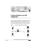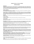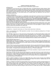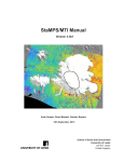
1
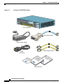
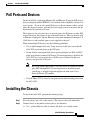
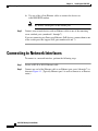
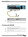
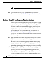
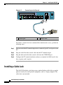
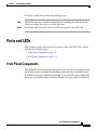
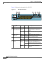
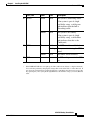
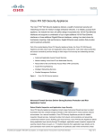
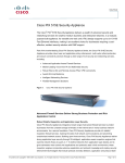
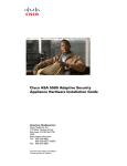
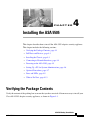
CH A P T E R
4
Installing the ASA 5505
This chapter describes how to install the ASA 5505 adaptive security appliance.
This chapter includes the following sections:
•
Verifying the Package Contents, page 4-1
•
PoE Ports and Devices, page 4-3
•
Installing the Chassis, page 4-3
•
Connecting to Network Interfaces, page 4-4
•
Powering on the ASA 5505, page 4-5
•
Setting Up a PC for System Administration, page 4-6
•
Optional Procedures, page 4-7
•
Ports and LEDs, page 4-9
•
What to Do Next, page 4-13
Verifying the Package Contents
Verify the contents of the packing box to ensure that you have received all items necessary to install your
Cisco ASA 5505 adaptive security appliance, as shown in Figure 4-1.
ASA 5505 Getting Started Guide
78-18003-02
4-1
Chapter 4
Installing the ASA 5505
Verifying the Package Contents
Figure 4-1
Contents of ASA 5505 Package
Securit
y
Service
s
Card Slo
t
POWER
48
VDC
CONSO
LE
7 POWER
over ETH
ERNET
6
5
4
3
1
2
1
0
2
RESET
Cisco ASA 5505
Blue console cable
Power supply adapter
Yellow Ethernet cable
Cable
(US shown)
CoReg
u
Inf and mplialator
orm Sa nc y
f
ati ety e
on
05
55 ed
A rt
S ta
A S e
co g id
is tin u
C et G
G
Cis
co
Pr Fire ASA
od w
uc all 550
tC
5
D
Documentation
ASA 5505 Getting Started Guide
4-2
78-18003-02
Chapter 4
Installing the ASA 5505
PoE Ports and Devices
PoE Ports and Devices
On the ASA 5505, switch ports Ethernet 0/6 and Ethernet 0/7 support PoE devices
that are compliant with the IEEE 802.3af standard, such as IP phones and wireless
access points. If you install a non-PoE device or do not connect to these switch
ports, the adaptive security appliance does not supply power to the ports and the
device must be powered on its own.
These ports are the only ports that can provide power for IP phones or other PoE
devices. However, these ports are not restricted to that use. They can also be used
as Ethernet switch ports, like the Ethernet switch ports numbered 0 through 5. If
a PoE device is not attached, power is not supplied to the port.
When connecting PoE devices, use the following guidelines:
•
Use straight-through cable only. Using crossover cable does not enable the
ASA 5505 to provide power to the PoE ports.
•
Do not disable auto-negotiation (force speed and duplex) on E0/6 and E0/7
when using them to connect PoE devices. If auto-negotiation is disabled, the
ASA 5505 does not recognize that a PoE device is attached. In this case,
power is not provided to the port.
Note
•
Be careful when connecting a Cisco PoE device to a non-PoE switch
port (E0/0 through E0/5). If auto-negotiation is disabled for that
switch port, a network loopback might occur with some Cisco
Powered Device (PD) models.
Cisco IP Phone 7970 is always in low-power mode when drawing power from
the ASA 5505.
Installing the Chassis
To install the ASA 5505, perform the following steps:
Step 1
Place the chassis on a flat, stable surface. The chassis is not rack mountable.
Step 2
Connect Port 0 to the public network (that is, the Internet):
a.
Use a yellow Ethernet cable to connect the device to a switch or hub.
ASA 5505 Getting Started Guide
78-18003-02
4-3
Chapter 4
Installing the ASA 5505
Connecting to Network Interfaces
b.
Use one of the yellow Ethernet cables to connect the device to a
cable/DSL/ISDN modem.
Note
Step 3
By default, switch port 0 is the outside port.
Connect your network devices with an Ethernet cable to one of the remaining
seven switched ports (numbered 1 through 7).
If you are connecting any Power over Ethernet (PoE) devices, connect them to one
of the switch ports that support PoE (ports numbered 6 and 7).
Connecting to Network Interfaces
To connect to a network interface, perform the following steps:
Step 1
Locate an RJ-45 to RJ-45 Ethernet cable.
Step 2
Connect one end of the Ethernet cable to an Ethernet port (ports 0 through 7) as
shown in Figure 4-2. (Typically Ethernet port 0 is used to connect to an Internet
router.)
ASA 5505 Getting Started Guide
4-4
78-18003-02
Chapter 4
Installing the ASA 5505
Powering on the ASA 5505
Connecting to an Ethernet Interface
Security
Services
Card Slot
Console
2
POWER
48VDC
RESET
1
7 POWER over ETHERNET 6
5
4
3
2
1
0
153761
Figure 4-2
1
2
1
Step 3
Ethernet switch ports
2
Ethernet cable
Connect the other end of the Ethernet cable to a device, such as a router, desktop
computer, or printer.
Powering on the ASA 5505
To power on the ASA 5505, perform the following steps:
Step 1
Connect the power supply with the power cable.
Step 2
Connect the small, rectangular connector of the power supply cable to the power
connector on the rear panel.
Step 3
Connect the AC power connector of the power supply input cable to an electrical
outlet.
ASA 5505 Getting Started Guide
78-18003-02
4-5
Chapter 4
Installing the ASA 5505
Setting Up a PC for System Administration
Note
Step 4
The ASA 5505 does not have a power switch. Completing Step 3 powers
on the device.
Check the power LED; if it is solid green, then the device is powered on.
For more information, see the “Front Panel Components” section on page 4-9.
Setting Up a PC for System Administration
You can perform setup, configuration and management tasks from a PC using the
command-line interface or with the Adaptive Security Device Manager (ASDM)
application, which provides an intuitive graphical user interface (GUI).
In addition to configuration and management capability, ASDM also provides
configuration wizards for initial configuration, VPN configuration, and
high-availability configuration.
For more information about using ASDM for setup and configuration, see
Chapter 5, “Configuring the Adaptive Security Appliance.”
To set up a PC from which you can configure and manage the ASA 5505, perform
the following steps:
Step 1
Make sure that the speed of the PC interface to be connected to one of the ASA
5505 inside ports is set to autonegotiate. This setting provides the best
performance.
By default, the ASA 5505 automatically negotiates the inside interface speed. If
autonegotiate is not an option for the PC interface, set the speed to either 10 or
100 Mbps half duplex. Do not set the interface to full duplex; this causes a duplex
mismatch that significantly impacts the total throughput capabilities of the interface.
Step 2
Configure the PC to use DHCP (to receive an IP address automatically from the
ASA 5505), which enables the PC to communicate with the ASA 5505 and the
Internet as well as to run ASDM for configuration and management tasks.
Alternatively, you can assign a static IP address to your PC by selecting an address
in the 192.168.1.0 subnet. (Valid addresses are 192.168.1.2 through
192.168.1.254, with a mask of 255.255.255.0 and default route of 192.168.1.1.)
ASA 5505 Getting Started Guide
4-6
78-18003-02
Chapter 4
Installing the ASA 5505
Optional Procedures
When you connect other devices to any of the inside ports, make sure that they do
not have the same IP address.
Note
The MGMT interface of the adaptive security appliance is assigned
192.168.1.1 by default, so this address is unavailable.
Step 3
Use an Ethernet cable to connect the PC to a switched inside port on the rear panel
of the ASA 5505 (one of the ports numbered 1 through 7).
Step 4
Check the LINK LED to verify that the PC has basic connectivity to the ASA
5505.
When connectivity is established, the LINK LED on the front panel of the ASA
5505 lights up solid green.
You can now access the ASDM and the ASDM Startup Wizard. See Chapter 5,
“Configuring the Adaptive Security Appliance” for information about how to
perform initial setup and configuration of the ASA 5505.
Optional Procedures
This section describes how to perform tasks that are not required for the initial
setup of the ASA 5505. This section includes the following topics:
•
“Connecting to the Console” section on page 4-7
•
“Installing a Cable Lock” section on page 4-8
Connecting to the Console
You can access the command line for administration using the console port on the
ASA 5505. To do so, you must run a serial terminal emulator on a PC or
workstation as shown in Figure 4-3.
ASA 5505 Getting Started Guide
78-18003-02
4-7
Chapter 4
Installing the ASA 5505
Optional Procedures
Figure 4-3
Connecting to the Console
Security
Services
Card Slot
Console
2
POWER
48VDC
RESET
1
7 POWER over ETHERNET 6
5
4
3
2
1
0
2
1
Console port
2
153760
1
Console cable
To connect a console for local, command-line administrative access, perform the
following steps:
Step 1
Plug one end of the PC terminal adapter into a standard 9-pin PC serial port on your
PC.
Step 2
Plug one end of the blue console cable into the PC terminal adapter.
Step 3
Plug the other end of the blue console cable into the CONSOLE port.
Step 4
Configure the PC terminal emulation software or terminal for 9600 baud, 8 data
bits, no parity, and 1 stop bit.
Installing a Cable Lock
The ASA 5505 includes a slot that accepts standard desktop cable locks to provide
physical security for small portable equipment, such as a laptop computer. The
cable lock is not included.
ASA 5505 Getting Started Guide
4-8
78-18003-02
Chapter 4
Installing the ASA 5505
Ports and LEDs
To install a cable lock, perform the following steps:
Step 1
Follow the directions from the manufacturer for attaching the other end of the
cable for securing the adaptive security appliance.
Step 2
Attach the cable lock to the lock slot on the back panel of the ASA 5505.
Ports and LEDs
This section describes the front and rear panels of the ASA 5505. This section
includes the following topics:
•
Front Panel Components, page 4-9
•
Rear Panel Components, page 4-12
Front Panel Components
The LINK/ACT indicators on the front panel of the ASA 5505 are normally solid
green when a link is established and flashing green when there is network activity.
Each Ethernet interface (numbered 0 through 7) has two LEDs: one to indicate the
operating speed and the other to indicate whether the physical link is established.
ASA 5505 Getting Started Guide
78-18003-02
4-9
Chapter 4
Installing the ASA 5505
Ports and LEDs
Figure 4-4 illustrates the front panel of the ASA 5505.
Figure 4-4
ASA 5505 Front Panel
1
3
2
4
LINK/ACT
6
5
Power
Status
Active
7
VPN
SSC
0
0
0
0
0
0
0
0
Cisco ASA 5505 series
Adaptive Security Appliance
0
Port / LED
Color
State
1
USB Port
—
—
Reserved for future use.
2
Speed Indicators Not lit
—
Network traffic is flowing at 10
Mbps.
3
4
Green
On
Network traffic is flowing at 100
Mbps.
Link Activity
Indicators
Green
Solid
The physical link established.*
Green
Flashing
There is network activity.
Power
Green
On
The device is powered on.
Off
5
Description
Status
Green
Amber
—
The device is powered off.
Flashing
The power-up diagnostics are
running or the system is booting.
Solid
The system is operational.
Solid
The system has encountered a
problem.
ASA 5505 Getting Started Guide
4-10
78-18003-02
153382
100 MBPS
Chapter 4
Installing the ASA 5505
Ports and LEDs
6
Port / LED
Color
State
Description
Active
Green
Solid
The system is forwarding traffic.
If the system is part of a high
availability setup, a solid green
light indicates that the link is
forwarding traffic.
Amber
Solid
The system is on standby.
If the system is part of a high
availability setup, a solid amber
light indicates that this is the
standby unit.
7
VPN
Green
Amber
8
*
SSC
—
Solid
The VPN tunnel is established.
Flashing
The system is initiating the VPN
tunnel.
Solid
The tunnel failed to initiate.
—
An SSC card is present in the SSC
slot.
If the LINK/ACT LED does not light up, the link could be down if there is a duplex mismatch.
You can fix the problem by changing the settings either on the ASA 5505 or on the other end. If
auto-negotiation is disabled (it is enabled by default), you might be using the wrong type of cable.
Try replacing the yellow (straight-through) Ethernet cable with the orange (crossover) Ethernet
cable.
ASA 5505 Getting Started Guide
78-18003-02
4-11
Chapter 4
Installing the ASA 5505
Ports and LEDs
Rear Panel Components
Figure 4-5 illustrates the back panel of the ASA 5505.
Figure 4-5
ASA 5505 Rear Panel
1
4
3
2
Security
Services
Card Slot
Console
RESET
1
7 POWER over ETHERNET 6
5
4
3
8
2
7
1
0
6
5
Port or LED
Purpose
1
Power connector
Attaching the power cord.
2
Security service card slot
Reserved for future use.
3
Serial console port
Managing the device using the CLI (command-line interface).
4
Lock device
Reserved for future use.
5
RESET button
Reserved for future use.
ASA 5505 Getting Started Guide
4-12
78-18003-02
153383
2
power
48VDC
Chapter 4
Installing the ASA 5505
What to Do Next
6
2 USB ports v2.0 ports
Reserved for future use.
7
Ethernet switch ports 0–7
Layer 2 switch ports that provide flexible VLAN configuration.
Note
8
PoE switch ports 6–7
Ethernet switch ports 6 and 7 also support PoE devices. If
a PoE device is not attached, power is not supplied to the
port and the device must be powered on its own.
Can be used for PoE devices, that is, devices that can be powered by
the network interface, such as IP phones.
These ports are the only ports that can be used for IP phones or other
PoE devices. However, these ports are not restricted to that use.
They can also be used as Ethernet switch ports, as are the ports
numbered 0 through 5. If a PoE device is not attached, power is not
supplied to the port and the device must be powered on its own.
What to Do Next
Continue with Chapter 5, “Configuring the Adaptive Security Appliance.”
ASA 5505 Getting Started Guide
78-18003-02
4-13
Chapter 4
Installing the ASA 5505
What to Do Next
ASA 5505 Getting Started Guide
4-14
78-18003-02